Embed Size (px)
Citation preview

Assessment of the V&V Challenges of Accident Tolerant Fuels
Koroush ShirvanPrincipal Research ScientistDirector of MIT ATF IRP
Department of Nuclear Science and EngineeringMultiphysics Model Validation Workshop
June 28, 2017

Outline• ATF IRP Overview
• ATF Materials Fabrication Technology
• Examples of V&V Needs
• Concluding Remarks
2
Acknowledgements: Funding for this work has been provided by DOE IRP contract # DE-NE0008416 and Center for Advanced Nuclear Energy Systems.

Accident Tolerant/Advanced Technology Fuel Program (Recent)
3
Shirvan K., et al., NED 270
(2014)
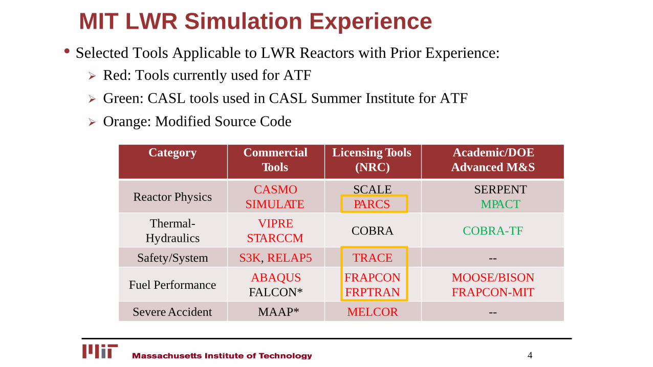
MIT LWR Simulation Experience• Selected Tools Applicable to LWR Reactors with Prior Experience:
Red: Tools currently used for ATF Green: CASL tools used in CASL Summer Institute for ATF Orange: Modified Source Code
4
Category Commercial Tools
Licensing Tools (NRC)
Academic/DOE Advanced M&S
Reactor Physics CASMO SIMULATE
SCALE PARCS
SERPENTMPACT
Thermal-Hydraulics
VIPRE STARCCM COBRA COBRA-TF
Safety/System S3K, RELAP5 TRACE --
Fuel Performance ABAQUSFALCON*
FRAPCON FRPTRAN
MOOSE/BISON FRAPCON-MIT
Severe Accident MAAP* MELCOR --

MIT ATF Experimental Facilities• Limited Sample Testing is Underway
5
Upto 1500oC Steam/Air Oxidation
400-500oC Steam OxidationPWR CRUD Loop
Prototypic 4-Point Bend TestPrototypic Pressure Tube Test
Burst Test (Plug & Liquid)Mechanical/Thermal Creep
Full Surface CharacterizationUpto 1500oC Quench TestSS/Transient CHF Testing
Ion IrradiationMITR PWR Loop
Post-Irradiation Examination (Dimension, SEM, Wettability)
Experimental Facilities

DOE ATF Integrated Research Project
6
• Goal: Estimate Time-to-Failure Failure Modes and a Framework• Lead: MIT Co-Lead: UW, PSU, TAMU, ANATECH, AREVA• Budget & Timeline: $3 million and 3 years (started Dec 2015)• ATF Candidates: Clad: FeCrAl, Mo, Cr Fuel: Additives/Dopants
BISON
FRAPCON/ FRAPTRAN
Integral Fuel Performance
ABAQUS
Structural Mechanics
Thermal Hydraulics
TRACE
MELCOR
FALCON*
Workhorse!
Code-to-Code Comparison
*Under license negotiation between EPRI and ANATECH
• Steady State: Minimal Neutronics Impact Durability (SCC, Plasticity, Fatigue) PCI (startup, power ramps)
• Design Basis Accident (DBA) LOCAs, RIAs, LOFA Oxidation, Fracture/Rupture, PCI CHF, Quench Characteristics
• Beyond DBAs-Severe Accidents (SAs) LBLOCA w/o SI, SBO (long/short term) Oxidation, Fracture/Rupture of All Primary
Components Fuel PCI, Buckling & Quench Performance
Strategy

Estimation of Time-to-Failure
7
• Historically NRC has relied on MELCOR Type Severe Accident Tools• TRACE may provide a more physics-based and accurate approach to time of fuel failure• Historically, Fuel Performance (FP) tools development aimed to address the ability of the fuel to
remain in a coolable geometry under accident,
Increase in computational power may allow FP to address coping time.
• ATF IRP approach is to use all three approaches!
MELCOR [Left] Short Term Station Blackout and TRACE [Right] LBLOCA w/o Safety Injection
From: Wang, J., et al., NED 313, 468 (2017)
From: Gurgan, A., Shirvan, K., ANS Summer (2017)

ATF Materials (Most Popular!)
8
FeCrAl
FeCrAl
Mo Zr
SiC SiCFiber
Cr
Cr2O3
Mo
SiCBeO
Cr
U3Si2 UN
TRISO
LCVD
Claddings
Monolayer
Composites/Coatings
High Density
Fuels
Additives/Dopants
High Temperature/
Retention
Green: Fuel Cycle Cost Benefit

ATF Cladding Materials
9
FeCrAl
FeCrAl
Mo Zr
SiC SiCFiber
Cr
Claddings
Monolayer
Composites/Coatings
Concept Max Temp. CommentsFeCrAl Monolayer Clad ~1500 oC Melting PointZirc with Cr Coating ~1330 oC Eutectic Melt PointZirc with Mo + Cr Coating ~ 1900 oC Depends on Thickness and
Inner Layer OxidationZirc with Mo + FeCrAl/Zr ~1900 oC Depends on Thickness and
Inner Layer OxidationSiC with SiCf Composite > 2000 oC Depends on ArchitectureSiCf with Cr Coating ~ 1900 oC Cr is there for Normal Ops.Zirc with SiCf with Cr ~1900 oC Melt point of Zr and Cr
• Maximum Allowable Temperature (Max Temp.) FeCrAl Cladding limit is the most certain Zr/Cr limit is for slow transients Mo limit depends on its structural role
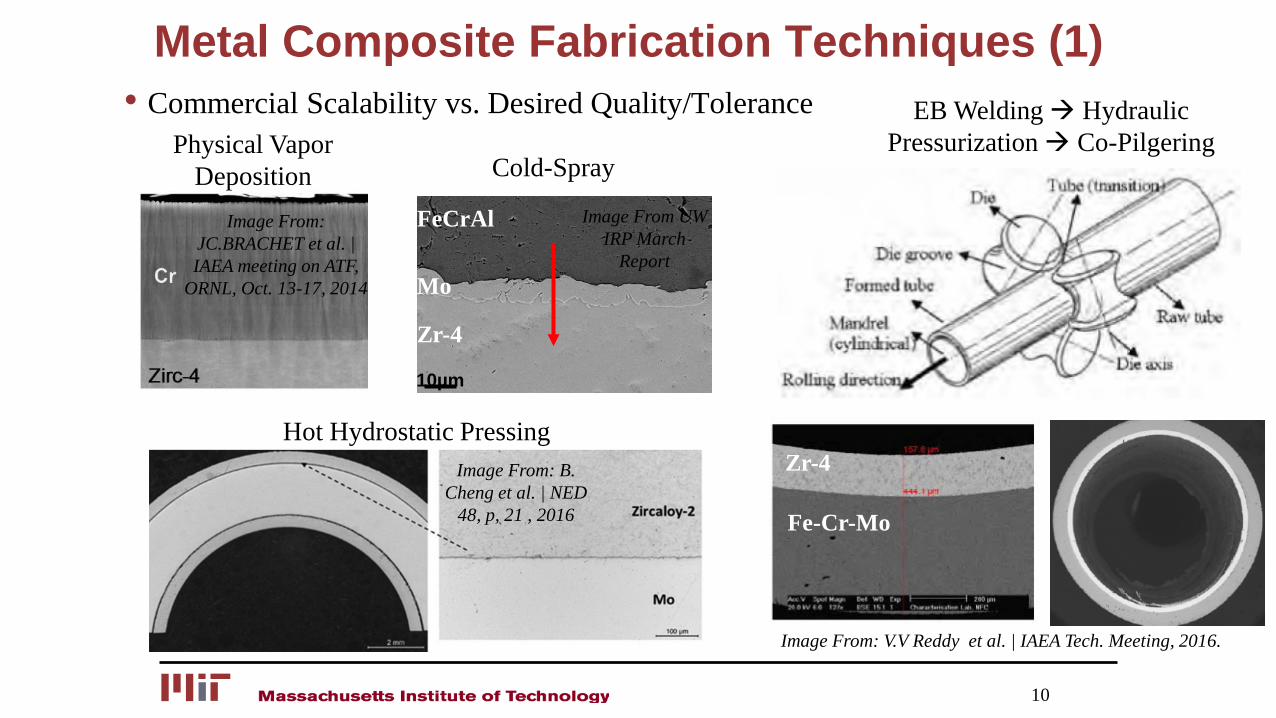
Metal Composite Fabrication Techniques (1)• Commercial Scalability vs. Desired Quality/Tolerance
10
Physical Vapor Deposition
Image From: JC.BRACHET et al. | IAEA meeting on ATF,
ORNL, Oct. 13-17, 2014
10µm
Image From UW IRP March
ReportMo
Zr-4
FeCrAl
Cold-Spray
Hot Hydrostatic PressingImage From: B.
Cheng et al. | NED 48, p, 21 , 2016
EB Welding Hydraulic Pressurization Co-Pilgering
Zr-4
Fe-Cr-Mo
Image From: V.V Reddy et al. | IAEA Tech. Meeting, 2016.

Metal Composite Fabrication Techniques (2)
11
Images courtesy of Kim H.G, TopFuel 2016

SiC Ceramic/Metallic Composite Fabrication Technique
12
Laser Driven Chemical Vapor Deposition Method (courtesy of Free-
Form-Fiber)
Start with Monolith SiCWind SiC
Fibers Infiltrate SiCMatrix CVD Barier
Wind SiC Fibers Infiltrate SiC Matrix Thick CVD Barrier
Plasma Spray of Chromia
(http://www.gordonengland.co.uk/xpmg23.htm)

Cladding Fuel Performance Simulation Metrics
Thermo-MechanicalDensity
Thermal ConductivityEmissivity
Thermal ExpansionElastic ModulusPosisson Ratio
Swelling/GrowthThermal Creep (primary, etc)
Irradiation CreepHigh Temperature Creep
Plasticity/Irradiation HardeningMeyer Hardness
Cladding Damage Mechanisms
13
Waterside CorrosionCorrosion Layer Growth/CRUD
(phase/stage dependent)Thermal conductivity of
Corrosion LayerPhase Transformation
Radiation Induced SegregationStress Corrosion Cracking
(i.e. Intergranular)Hydrogen Pickup Fraction
Hydrogen MigrationHydride Formation
Strength/Ductility Degradation from Hydrogen
• What information can we get from experiments?
• What information do we need to simulate time of failure?
Fuel IntegralPellet to Cladding Mechanical
Interaction (PCMI)Pellet-to-Cladding Chemical
Interaction (Especially w/HBS)Fuel Burst (LOCAs)
Fuel Assembly StructuralInteraction
Lift-offFuel-Clad Gap Evolution and
Heat TransferMechanical Shock/SeismicGrid-to-Rod Fretting/Wear
Tritium Release

M&S Tools Challenges
14
Metrics Tools AddressPlasticity/Large Deformation BISON/FRAPTRAN FEA/EmpiricalFracture Failure/Post Burst Behavior ABAQUS/BISON FEA + Empirical
Critical Heat Flux/Post-CHF/Quench TRACE/BISON Empirical
Stress Corrosion Cracking BISON/FRAPCON EmpiricalCorrosion/CRUD Deposition BISON/FRAPCON EmpiricalMechanical Shock/Impact ABAQUS FEA/EmpericalMulti-Layer Interaction BISON/FRAPCON FEA/Improved Model
Extended Gap Opening BISON/FRAPCON Improved Model/Empirical
Non-Fuel Structure Performance during SA TRACE Empirical/Improve
Model
Images From: C.P. Massey et al., JNM 470 (2016) 134
Note: TRACE has capability for time-dependent geometric feedback of fuel cladding.

Examples
• Coated Cladding Fuel Performance
• SiC Cladding Failure Mode
• SiC Integral Fuel Performance
• Cladding Water-Side Heat Transfer
15

Coated Cladding Fuel Performance
Page 16
Cladding/Coating Material & ThicknessCladding Coating(s) Power HistoryM5 / Zr4 / ZIRLO Cr Mo FeCrAl
Case 1. M5/Zr4/ZIRLO + Cr Coating 521.5μm 50 µm - - Constant @ 18 kW/mCase 2. M5/Zr4/ZIRLO + Cr Coating 521.5μm 50 µm - - PWR Power HistoryCase 3. M5/Zr4/ZIRLO + Mo/FeCrAl Coating 521.5μm - 20 µm 30 µm Constant @ 18 kW/mCase 4: M5/Zr4/ZIRLO + Mo/FeCrAl Coating 521.5μm - 20 µm 30 µm PWR Power History
…M5/Zr4/ZIRLO Mo FeCrAl Cr…M5/Zr4/ZIRLO
Mo + FeCrAl Coating Cr Coating

Coated Cladding Fuel Performance (2)
17

Coated Cladding Fuel Performance (3)• Steady-State Plasticity = Uncertainty in Performance
18
Cr-Coated FeCrAl-Mo-Coated

Coated Cladding Fuel Performance (4)• Currently not part of any regulatory limit:
Likely if Credit to ATF is Requested
19

SiC Cladding Failure Mode• Different layers (Monolith vs. Composite) have different thermo-mechanical
property Irradiation swelling strain is in opposite direction to thermal strain.
20
Stress @ Shutdown:Thermal strain that is
going against radiation induced
swelling strain is very small at shutdown.

SiC Cladding Failure Mode (2)• Can stress-induced failures meet current fuel failure standards (1 ppm)?
21
From: Mieloszyk, Shirvan et al., ANFM, 2015

SiC Cladding Failure Mode (3)• Important lesson learned from 2014 MIT SiC Modeling Workshop
22
PIE Figure From Morris et al., ORNL-24 (4-00), 2014
Image From: https://atrnsuf.inl.gov/documents/review2016/161102_Ka
toh_NSUF-APR_Rad-HHF-synergism%20R1.pdf
Weak Modeling & Simulation Strong Modeling & Simulation

SiC Integral Fuel Performance
23
• SiC cladding results in significant increase in UO2 temperature. SiC irradiated thermal conductivity is almost 1/3 of Zircaloy. SiC lack of creep down also contributes to this higher fuel temperature.
* Simulation Performed with FRAPCON-MIT, 2014
700800900
1000110012001300140015001600
0 250 500 750 1000 1250 1500
Ave
rage
Fue
l Tem
pera
ture
(K
)
Time (Days)
Zirc-4SiC
0
3
6
9
12
15
18
21
24
0 250 500 750 1000 1250 1500
Plen
um P
ress
ure
(MPa
)
Time (Days)
Zirc-4
SiC

SiC Integral Fuel Performance (2)• How can we reduce the fuel temperature:
Fuel w/additives or gap fillers
• How confident are we in fuel temperature predictions:
24
SiC Fuel Performance FRAPCON BISONMax Beginning of Life T (K) 1631 1606Max End of Life T (K) 1852 2288Max Plenum Pressure (MPa) 14.2 35Max FGR (%) 28.6 53.6
Zr-4 Fuel Performance FRAPCON BISONMax Beginning of Life T (K) 1367 1352Max End of Life T (K) 1574 1656Max Plenum Pressure (MPa) 11.1 11.1Max FGR (%) 11.9 8.6
Table from: Shirvan, ICAPP ‘14

SiC Integral Fuel Performance (3)
25
• Gap remains open for extended period of time for SiC case. Typical fuel performance validation data are integral
UO2 FRAPCON assessment cases as a function of burnup[Fig. from https://www.nrc.gov/docs/ML1110/ML11101A006.pdf]
Cracking models could account for over 50% of gap
closure

Cladding Water-Side Heat Transfer• Departure from nucleate boiling (and dryout) during steady-state and fast/slow
transients needs to be measured for different ATF surfaces Large V&V challenge without prototypic size testing (e.g. Scaling)
26
What are the effect of gammas and
neutrons?
Recent Pool Boiling Data
show Zr and Cr to be similar
From: Seo et al., JHMT, 102, 2016
Sample Condition Zirc-4 FeCrAl Zirc-4 FeCrAlAs Machined 0.352 0.651 83.5o 79.7o
Oxidized 0.424 0.712 48.2o 39.4o
Quench Sample 0.312 0.384 83.1o 81.1o
Roughness (µm) Contact Angle
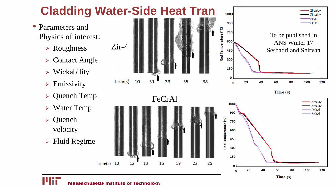
Cladding Water-Side Heat Transfer (2)• Parameters and
Physics of interest: Roughness Contact Angle Wickability Emissivity Quench Temp Water Temp Quench
velocity Fluid Regime
27
Zir-4
FeCrAl
To be published in ANS Winter 17
Seshadri and Shirvan

Severe Accident Progression• Accident Sequence:
Steady State (leading up to accident)
Blowdown/Boil off/Rod Burst
Heat up to Primary System Failure (e.g. hot log creep rupture) Depressurize
Heat up and Core Melt If Nothing is Done!
• If extended grace period is credited then New Failure Modes during the BDBA sequence need investigation.
28
TRACE PWR Simulation of SBO

Concluding Remarks• State-of-Art high fidelity simulation resources are needed to design smart
out-of-pile/in-pile experiments and assess ATF time-to-failure
• Much research needs to still focus on failure modes to allow for an informed UQ analysis.
• Despite tremendous progress in M&S, V&V of many key parameters still requires proto-typical geometry and conditions (e.g. irradiation/Temp/P).
• Close collaboration of all organization involved in nuclear R&D is critical for ATF development. Lets Join Forces to Tackle the ATF Challenge Problem!
29