Embed Size (px)
Citation preview
ISSN: 0128-7680Pertanika J. Sci. & Technol. 18 (1): 155 – 166 (2010) © Universiti Putra Malaysia Press
Received: 13 October 2008 Accepted: 26 November 2009*Corresponding Author
Assessment of Using Tunneling and Trenchless Technology for Constricting Twin Box Culvert
Thamer Ahmad Mohammad1*, Mohd. Razali Abdul Kadir1, Megat Johari Megat Mohd. Noor1 and Ahmad Husaini Sulaiman2
1Department of Civil Engineering, Faculty of Engineering,Universiti Putra Malaysia, 43400 UPM, Serdang, Selangor, Malaysia
2Department of Irrigation and Drainage, 50626 Kuala Lumpur, Malaysia *E-mail: [email protected]
AbstrActPart of the Seremban flood mitigation project in the state of Negeri Sembilan, Malaysia is to mitigate the flood at Jalan Rasah. The mitigation is planned to be implemented in packages. Package I and Package II of River Anak Air Rasah are parts of the project work. In these packages, wider and deeper concrete sections for the river are constructed. The existing undersized culverts were replaced by bigger reinforced concrete box culverts. The size of the box culverts was based on 100-years average reoccurrence interval (ARI). One of these culverts intersected with a rail line connecting Singapore and Malaysia. Trenchless jacking technique was used to lay the box culvert. The total length of the box culvert jacked under the railway line is 33 m, whereas the total width of the twin box culvert is 7.8 m with a total height of 3 m. This was the first time that the trenchless jacking techniques were used for the urban flood mitigation purpose in Malaysia, and it is mainly used to minimise traffic disruption. This study reports the success of using jacking technique in the development of the flood mitigation program of DID in Negeri Sembilan. Among other things, it explains significant performance of the technique under local conditions and experiences gained towards the advancement of tunnelling and trenchless technology.
Keywords: Jacking technique, twin box culvert, construction, flood mitigation
ABBReviATioN
ARI : Average Reoccurrence Interval BS : British Standards DID : Department of Irrigation an Drainage LRT : Light Transit Rail NATM : New Austrian Tunnelling Method
iNTRodUCTioNTunnelling and trenchless technique is not new in the construction sector. It has been used for decades and many projects around the world have successfully been constructed using this technique. Recently, new technologies which employ trenchless technique are used and this has increased the experiences in this field. Several reasons behind the use of the tunnelling technique in construction are shortage of land availability, intersection with existing strategic traffic routes and water ways, as well as the existence of historical buildings at the project site.
Thamer Ahmad Mohammad et al.
156 Pertanika J. Sci. & Technol. Vol. 18 (1) 2010
The tunnelling and trenchless technique is used in construction worldwide and recently, this technique was used to construct lines 2 and 3 of the Athens Metro in Greece (Leto and Welburm, 1999). In Egypt, it was used to construct the El-Azhar road tunnel in Cairo (Welburn and De Nettancourt, 2002). In United Kingdom, the method was used in the construction of Euro Tunnel and also the large wastewater sewers like the Southern Water’s Coastal Clean-up Programme (Peacock and Setterfield, 1999). Meanwhile, a new tunnelling technique, known as New Austrian Tunnelling Method (NATM) was used in the construction of London Bridge Station on Jubilee Line and this technique was used recently in Germany, Austria and some other developed countries. Several tunnels, with diameters ranging between 5.35 m to 13.67 m and length from 45 m to 50 m, were constructed in the Jubilee Line Project (Field et al., 2000). Denmark and Sweden are linked with a road and a rail line which were opened in July, 2000. The length of the trenchless immersed tunnel is 3510 m, comprising of 20 elements and each element is longitudinally divided into eight segments. The overall section of the immersed tunnel is 41.7 m wide and 8.5 m high. The cross section was designed in such a way that it would achieve the required uplift with 10.6 factor of safety. The design was done according to Euro Code 2. Table 1 shows the loading conditions considered in the design of the immersed tunnel. The jacking technique was used to move 55000 tonnes of tunnel elements. The construction period was exactly 5 years (Busby and Marshall, 2000).
TABLe 1 Loads considered in the design of immersed tunnel
Permanent loads Imposed loads Accidental loads
Structural concrete Road traffic load Ice
Ballast concrete Train load explosion
Pavement construction Water level variations Road vehicle collision
Track form Temperature Train collision
M&e equipments ------------------------------ Sunken ship
Hydraulic pressure ------------------------------ Falling anchor
earth pressure ------------------------------ Earthquake
Differential settlement ------------------------------ Flooding
Source: Mainwaring et al., 2000
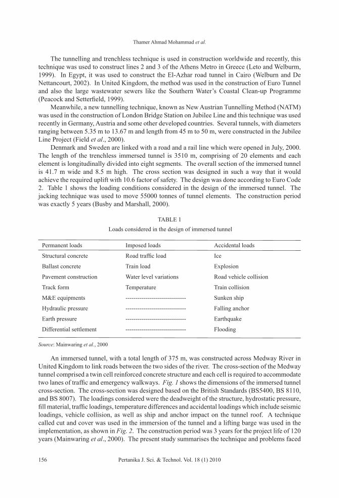
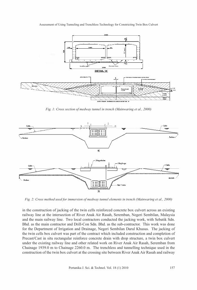
An immersed tunnel, with a total length of 375 m, was constructed across Medway River in United Kingdom to link roads between the two sides of the river. The cross-section of the Medway tunnel comprised a twin cell reinforced concrete structure and each cell is required to accommodate two lanes of traffic and emergency walkways. Fig. 1 shows the dimensions of the immersed tunnel cross-section. The cross-section was designed based on the British Standards (BS5400, BS 8110, and BS 8007). The loadings considered were the deadweight of the structure, hydrostatic pressure, fill material, traffic loadings, temperature differences and accidental loadings which include seismic loadings, vehicle collision, as well as ship and anchor impact on the tunnel roof. A technique called cut and cover was used in the immersion of the tunnel and a lifting barge was used in the implementation, as shown in Fig. 2. The construction period was 3 years for the project life of 120 years (Mainwaring et al., 2000). The present study summarises the technique and problems faced
Assessment of Using Tunneling and Trenchless Technology for Constricting Twin Box Culvert
Pertanika J. Sci. & Technol. Vol. 18 (1) 2010 157
Fig. 1: Cross section of medway tunnel in trench (Mainwaring et al., 2000)
Fig. 2: Cross method used for immersion of medway tunnel elements in trench (Mainwaring et al., 2000)
in the construction of jacking of the twin cells reinforced concrete box culvert across an existing railway line at the intersection of River Anak Air Rasah, Seremban, Negeri Sembilan, Malaysia and the main railway line. Two local contractors conducted the jacking work, with Sebatik Sdn. Bhd. as the main contractor and Drill-Con Sdn. Bhd. as the sub-contractor. This work was done for the Department of Irrigation and Drainage, Negeri Sembilan Darul Khusus. The jacking of the twin cells box culvert was part of the contract which included construction and completion of Precast/Cast in situ rectangular reinforce concrete drain with drop structure, a twin box culvert under the existing railway line and other related work on River Anak Air Rasah, Seremban from Chainage 1939.0 m to Chainage 2260.0 m. The trenchless and tunnelling technique used in the construction of the twin box culvert at the crossing site between River Anak Air Rasah and railway

Thamer Ahmad Mohammad et al.
158 Pertanika J. Sci. & Technol. Vol. 18 (1) 2010
line was the first work in the flood mitigation projects. In Malaysia, other governmental authorities like the Public Works Department, Railway Authorities, and private developers (such as Putra LRT Sdn. Bhd.) have been employing the tunnelling techniques quite often in their projects.
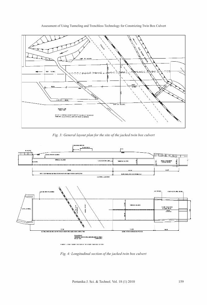
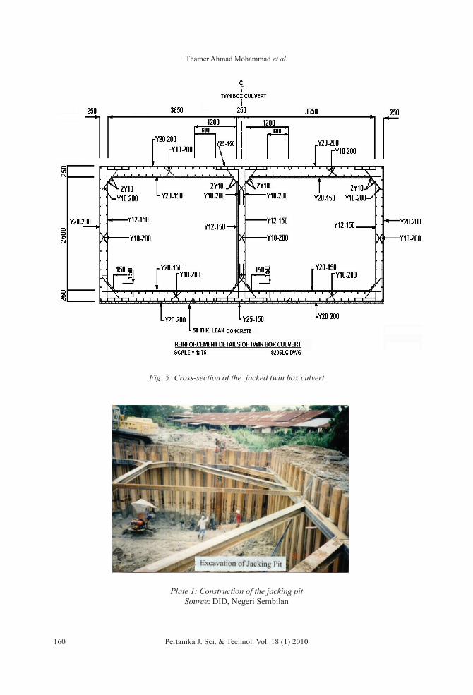
THe CASe STUdyUnder the Seremban flood mitigation project, an improvement work for River Anak Air Rasah was completed and this improvement included channelling and changing the watercourse of this natural monsoon drain. The improvement work were planned to be conducted in three phases. In Phases I and II, a total length of 1500 m from the River Anak Air Rasah watercourse has completely been improved, while Phase III is not started yet. The actual cost for the construction involved in Phase I and Phase II was RM 4.6 millions. In Phase I, the watercourse of River Anak Air Rasah, between chainage 2029 m and chainage 2079 m, was intersected with a railway line (Fig. 3). At this crossing, a 50 m length twin box culvert (3.65 m x 2.2 m) was constructed. Plan and elevation of the culvert are shown in Fig. 4. About 33 m of the total length of the twin box culvert was jacked underneath the railway line using the tunnelling and trenchless technique to avoid disturbances on the railway traffic. Meanwhile, around 17 m of the twin box culvert was located away from the railway line, so it was constructed using the normal method of construction. The jacked portion of the twin box culvert represented 66% of its total constructed length. The tunnelling and jacking work was done using the local expertise.
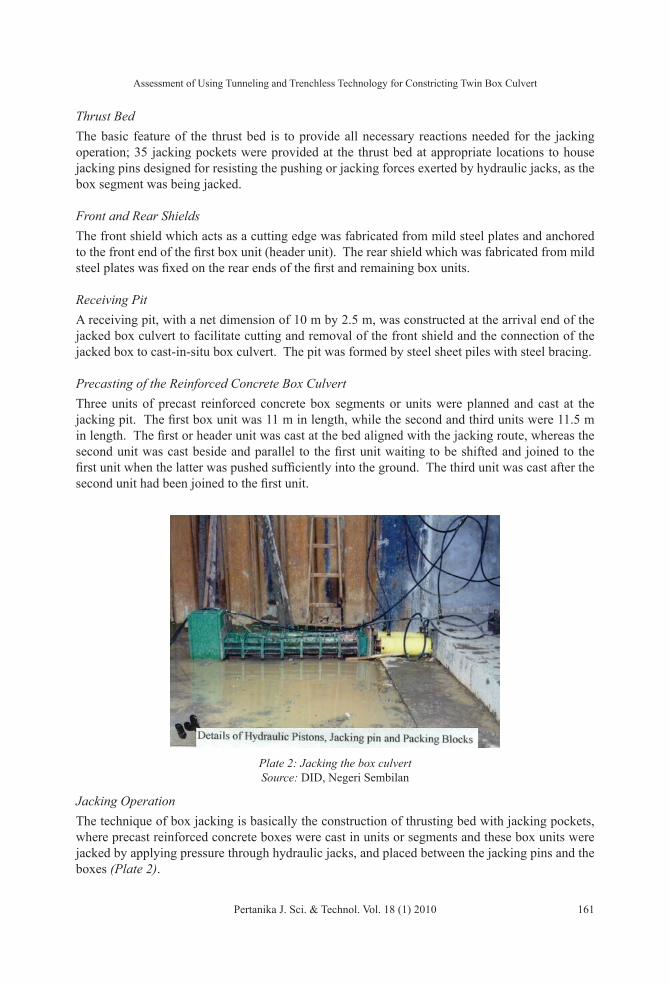
MeTHodologyThe jacked reinforced concrete twin box culvert was designed using the British standards, BS 5400: Part 2, BS 5400: Part 4 and BS 8110. The internal dimensions of the single cell of the twin box culvert are 2.2 m x 3.65 m. Meanwhile, the structural analysis of the twin box culvert was idealized as two-dimensional frame and was analysed by direct stiffness method using computer software. The soil overburden, concrete self weight, imposed vertical loads such as the weight of ballast, track, sleepers and rail axle loads, as well as the horizontal earth water pressures, and the jacking loads were considered for a number of load combinations to establish the most critical design. The concrete mix was designed and manufactured in a plant and then taken to the site by a transit mixer and a strict quality control was assured on the grade of the concrete. Grade 40 was used in order to allow for the high concrete stress during the jacking operation. Fig. 5 shows the details of the reinforcement used in the cross-section of the jacked twin box culvert. It is important to give an idea about the method used in construction and jacking of the twin box culvert, at the site of the intersection between River Anak Air Rasah and the main railway line in Seremban town. The construction technique comprises of jacking pits, thrust bed, front and rear shields, receiving pit, precast reinforced concrete twin box culvert and jacking mechanism. A brief description of the stages is given below:
Jacking PitA jacking pit which houses the thrust bed for the casting and jacking of the precast concrete box segments was constructed. The dimensions of the pit, as measured on plan, were 21.0 m x 15.5 m, with the excavation depth of about 6 m. The pit was formed by installing 9 to 12 m deep sheet-piles and braced by steel strut and wailer system (Plate 1).
Assessment of Using Tunneling and Trenchless Technology for Constricting Twin Box Culvert
Pertanika J. Sci. & Technol. Vol. 18 (1) 2010 159
Fig. 3: General layout plan for the site of the jacked twin box culvert
Fig. 4: Longitudinal section of the jacked twin box culvert
Thamer Ahmad Mohammad et al.
160 Pertanika J. Sci. & Technol. Vol. 18 (1) 2010
Fig. 5: Cross-section of the jacked twin box culvert
Plate 1: Construction of the jacking pit Source: DID, Negeri Sembilan
Assessment of Using Tunneling and Trenchless Technology for Constricting Twin Box Culvert
Pertanika J. Sci. & Technol. Vol. 18 (1) 2010 161
Thrust BedThe basic feature of the thrust bed is to provide all necessary reactions needed for the jacking operation; 35 jacking pockets were provided at the thrust bed at appropriate locations to house jacking pins designed for resisting the pushing or jacking forces exerted by hydraulic jacks, as the box segment was being jacked.
Front and Rear ShieldsThe front shield which acts as a cutting edge was fabricated from mild steel plates and anchored to the front end of the first box unit (header unit). The rear shield which was fabricated from mild steel plates was fixed on the rear ends of the first and remaining box units.
Receiving PitA receiving pit, with a net dimension of 10 m by 2.5 m, was constructed at the arrival end of the jacked box culvert to facilitate cutting and removal of the front shield and the connection of the jacked box to cast-in-situ box culvert. The pit was formed by steel sheet piles with steel bracing.
Precasting of the Reinforced Concrete Box Culvert Three units of precast reinforced concrete box segments or units were planned and cast at the jacking pit. The first box unit was 11 m in length, while the second and third units were 11.5 m in length. The first or header unit was cast at the bed aligned with the jacking route, whereas the second unit was cast beside and parallel to the first unit waiting to be shifted and joined to the first unit when the latter was pushed sufficiently into the ground. The third unit was cast after the second unit had been joined to the first unit.
Jacking OperationThe technique of box jacking is basically the construction of thrusting bed with jacking pockets, where precast reinforced concrete boxes were cast in units or segments and these box units were jacked by applying pressure through hydraulic jacks, and placed between the jacking pins and the boxes (Plate 2).
Plate 2: Jacking the box culvert Source: DID, Negeri Sembilan
Thamer Ahmad Mohammad et al.
162 Pertanika J. Sci. & Technol. Vol. 18 (1) 2010
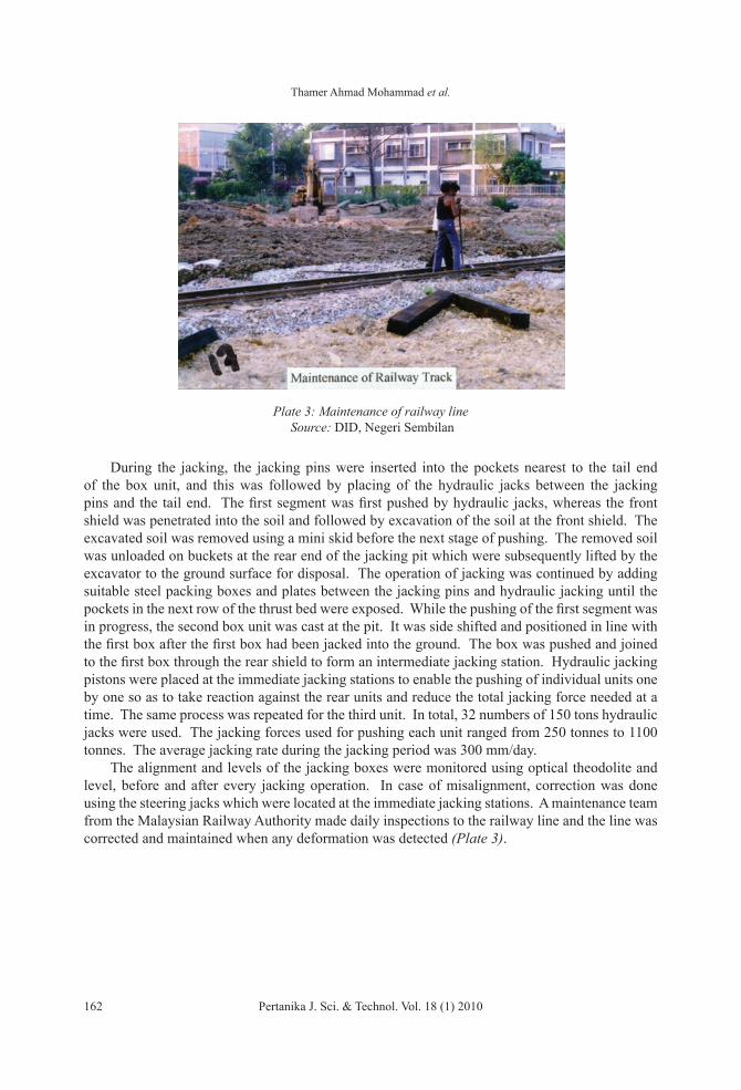
During the jacking, the jacking pins were inserted into the pockets nearest to the tail end of the box unit, and this was followed by placing of the hydraulic jacks between the jacking pins and the tail end. The first segment was first pushed by hydraulic jacks, whereas the front shield was penetrated into the soil and followed by excavation of the soil at the front shield. The excavated soil was removed using a mini skid before the next stage of pushing. The removed soil was unloaded on buckets at the rear end of the jacking pit which were subsequently lifted by the excavator to the ground surface for disposal. The operation of jacking was continued by adding suitable steel packing boxes and plates between the jacking pins and hydraulic jacking until the pockets in the next row of the thrust bed were exposed. While the pushing of the first segment was in progress, the second box unit was cast at the pit. It was side shifted and positioned in line with the first box after the first box had been jacked into the ground. The box was pushed and joined to the first box through the rear shield to form an intermediate jacking station. Hydraulic jacking pistons were placed at the immediate jacking stations to enable the pushing of individual units one by one so as to take reaction against the rear units and reduce the total jacking force needed at a time. The same process was repeated for the third unit. In total, 32 numbers of 150 tons hydraulic jacks were used. The jacking forces used for pushing each unit ranged from 250 tonnes to 1100 tonnes. The average jacking rate during the jacking period was 300 mm/day. The alignment and levels of the jacking boxes were monitored using optical theodolite and level, before and after every jacking operation. In case of misalignment, correction was done using the steering jacks which were located at the immediate jacking stations. A maintenance team from the Malaysian Railway Authority made daily inspections to the railway line and the line was corrected and maintained when any deformation was detected (Plate 3).
Plate 3: Maintenance of railway line Source: DID, Negeri Sembilan
Assessment of Using Tunneling and Trenchless Technology for Constricting Twin Box Culvert
Pertanika J. Sci. & Technol. Vol. 18 (1) 2010 163
ReSUlTS ANd diSCUSSioNThe following problems were encountered during the jacking operations:
Existence of Timber Logs and Other Hard Materials In the case of jacking, timber logs of varying sizes and other foreign material such as steel rails and boulders rendered difficulties in maintaining the alignment of the jacking path which resulted in high jacking force. These obstructions had to be cut and removed in small pieces, and doing so caused some stability problems at the heading face and slowed down the jacking program as well. Therefore, many sand bags had to be placed at the heading face to stabilise the soil during the removal of the obstructions.
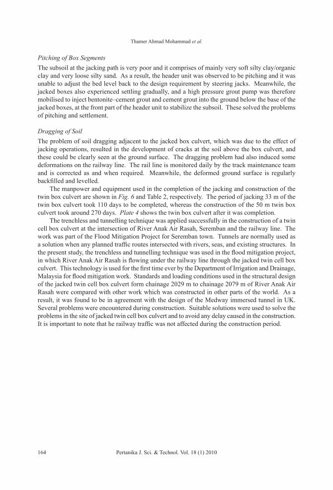
Fig. 6: Manpower used in the jacking technique
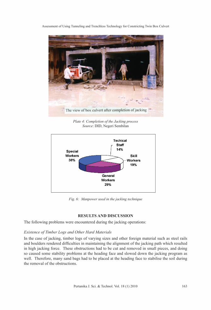
Plate 4: Completion of the Jacking process Source: DID, Negeri Sembilan
Thamer Ahmad Mohammad et al.
164 Pertanika J. Sci. & Technol. Vol. 18 (1) 2010
Pitching of Box SegmentsThe subsoil at the jacking path is very poor and it comprises of mainly very soft silty clay/organic clay and very loose silty sand. As a result, the header unit was observed to be pitching and it was unable to adjust the bed level back to the design requirement by steering jacks. Meanwhile, the jacked boxes also experienced settling gradually, and a high pressure grout pump was therefore mobilised to inject bentonite–cement grout and cement grout into the ground below the base of the jacked boxes, at the front part of the header unit to stabilize the subsoil. These solved the problems of pitching and settlement.
Dragging of SoilThe problem of soil dragging adjacent to the jacked box culvert, which was due to the effect of jacking operations, resulted in the development of cracks at the soil above the box culvert, and these could be clearly seen at the ground surface. The dragging problem had also induced some deformations on the railway line. The rail line is monitored daily by the track maintenance team and is corrected as and when required. Meanwhile, the deformed ground surface is regularly backfilled and levelled. The manpower and equipment used in the completion of the jacking and construction of the twin box culvert are shown in Fig. 6 and Table 2, respectively. The period of jacking 33 m of the twin box culvert took 110 days to be completed, whereas the construction of the 50 m twin box culvert took around 270 days. Plate 4 shows the twin box culvert after it was completion. The trenchless and tunnelling technique was applied successfully in the construction of a twin cell box culvert at the intersection of River Anak Air Rasah, Seremban and the railway line. The work was part of the Flood Mitigation Project for Seremban town. Tunnels are normally used as a solution when any planned traffic routes intersected with rivers, seas, and existing structures. In the present study, the trenchless and tunnelling technique was used in the flood mitigation project, in which River Anak Air Rasah is flowing under the railway line through the jacked twin cell box culvert. This technology is used for the first time ever by the Department of Irrigation and Drainage, Malaysia for flood mitigation work. Standards and loading conditions used in the structural design of the jacked twin cell box culvert form chainage 2029 m to chainage 2079 m of River Anak Air Rasah were compared with other work which was constructed in other parts of the world. As a result, it was found to be in agreement with the design of the Medway immersed tunnel in UK. Several problems were encountered during construction. Suitable solutions were used to solve the problems in the site of jacked twin cell box culvert and to avoid any delay caused in the construction. It is important to note that he railway traffic was not affected during the construction period.
Assessment of Using Tunneling and Trenchless Technology for Constricting Twin Box Culvert
Pertanika J. Sci. & Technol. Vol. 18 (1) 2010 165
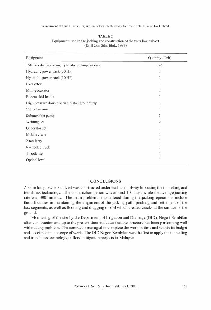
TABLe 2Equipment used in the jacking and construction of the twin box culvert
(Drill Con Sdn. Bhd., 1997)
Equipment Quantity (Unit)
150 tons double-acting hydraulic jacking pistons 32
Hydraulic power pack (30 HP) 1
Hydraulic power pack (10 HP) 1
excavator 1
Mini-excavator 1
Bobcat skid loader 1
High pressure double acting piston grout pump 1
Vibro hammer 1
Submersible pump 3
Welding set 2
Generator set 1
Mobile crane 1
2 ton lorry 1
6 wheeled truck 1
Theodolite 1
Optical level 1
CoNClUSioNSA 33 m long new box culvert was constructed underneath the railway line using the tunnelling and trenchless technology. The construction period was around 110 days, while the average jacking rate was 300 mm/day. The main problems encountered during the jacking operations include the difficulties in maintaining the alignment of the jacking path, pitching and settlement of the box segments, as well as flooding and dragging of soil which created cracks at the surface of the ground. Monitoring of the site by the Department of Irrigation and Drainage (DID), Negeri Sembilan after construction and up to the present time indicates that the structure has been performing well without any problem. The contractor managed to complete the work in time and within its budget and as defined in the scope of work. The DID Negeri Sembilan was the first to apply the tunnelling and trenchless technology in flood mitigation projects in Malaysia.
Thamer Ahmad Mohammad et al.
166 Pertanika J. Sci. & Technol. Vol. 18 (1) 2010
RefeReNCeSBusby, J. and Marshall, C. (2000). Design and construction of the Oresund Tunnel. Journal of the Institution
of Engineers, 138(4), 157-167.
Drill Con Sdn. Bhd. (1997). Jacking of twin box culvert under the existing railway track at Sungai Anak Air Rasah, Seremban. A study submitted to the Department of Irrigation and Drainage, Negeri Sembilan.
Field, C., Gamble, M. and Karakashian, M. (2000). Design and construction of London Bridge Station on Jubilee Line extension. Proceedings of the Institution of Engineers, Civil Engineering, 138(1), 26-39.
Leto and Welburn, B. (1999). Lines 2 and 3 of the Athens Metro. Proceedings of the Institution of Engineers, Civil Engineering, 132(2/3), 68-76.
Madkour, A., Hudson, M.A. and Bellarsoa, A. (1999). Construction of Cairo Metro Line 2. Proceedings of the Institution of Engineers, Civil Engineering, 132(2/3), 103-117.
Mainwaring, G.D., Week, C.R. and Brandson, C. (2000). The detailed design of the Medway Tunnel Project. Journal of the Institution of Civil Engineers, 141(1), 9-24.
Peacock, S. and Setterfield, G. (1999). South water’s costal clean-up programme. Proceedings of the Institution of Engineers, Civil Engineering, 132(2/3), 12-19.
Welburn, B. and De Nettancourt, X. (2002). El-Azhar Road Tunnel Cairo’s New Frontier. Proceedings of the Institution of Engineers, Civil Engineering, 150(3), 114-123.