Embed Size (px)
Citation preview
1325
0100
01
ADDITIONAL MATERIALS
In addition to this paper, you will require a calculator, a Case Study Booklet and a Data Booklet.
INSTRUCTIONS TO CANDIDATES
Use black ink or black ball-point pen. Do not use pencil or gel pen. Do not use correction fluid.Write your name, centre number and candidate number in the spaces at the top of this page.Write your answers in the spaces provided in this booklet. If you run out of space, use the continuation pages at the back of the booklet, taking care to number the question(s) correctly.
INFORMATION FOR CANDIDATES
This paper is in 3 sections, A, B, and C. Section A: 60 marks. Answer all questions. You are advised to spend about 1 hour on this section.Section B: 20 marks. The Case Study. Answer all questions. You are advised to spend about 20
minutes on this section.Section C: Options; 20 marks. Answer one option only. You are advised to spend about 20
minutes on this section.
JD*(S13-1325-01)
Surname
Other Names
CandidateNumber
2
CentreNumber
© WJEC CBAC Ltd.
GCE A level
1325/01
PHYSICSASSESSMENT UNIT PH5:Electromagnetism, Nuclei & Options
A.M. THURSDAY, 20 June 2013
1¾ hours
2
(1325-01)
Examineronly
SECTION A
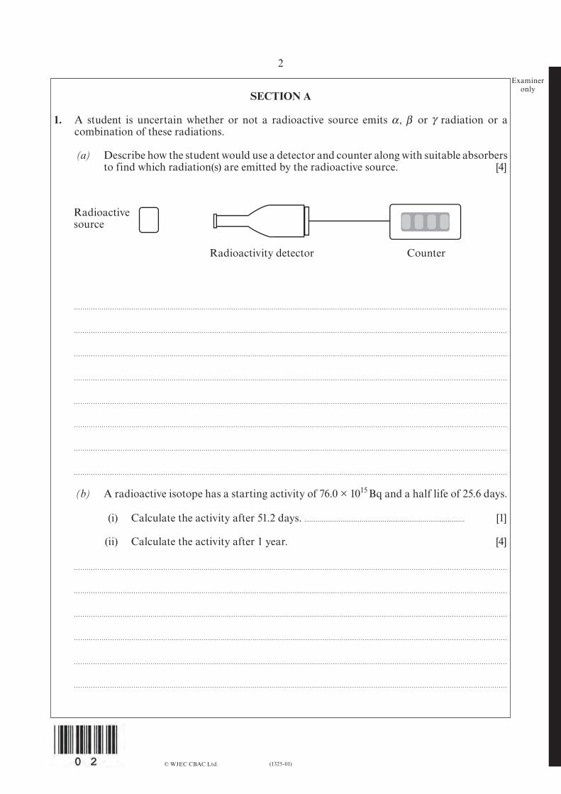
1. A student is uncertain whether or not a radioactive source emits or radiation or a combination of these radiations.
(a) Describe how the student would use a detector and counter along with suitable absorbers to find which radiation(s) are emitted by the radioactive source. [4]
© WJEC CBAC Ltd.
Radioactivesource
Radioactivity detector Counter
(b) A radioactive isotope has a starting activity of 76.0 × 10¹⁵ Bq and a half life of 25.6 days.
(i) Calculate the activity after 51.2 days. . . . . . . . . . . . . . . . . . . . . . . . . . . . . . . . . . . . . . . . . . . . . . . . . . . . . . . . . . . . . . . . . . . . . . . . . . . . . . . . . . . . . [1]
(ii) Calculate the activity after 1 year. [4]
α β, γ

(1325-01) Turn over.
1325
0100
03
3Examiner
only (iii) Calculate the number of radioactive nuclei present at the start. [2]
© WJEC CBAC Ltd.
4
(1325-01)
Examineronly
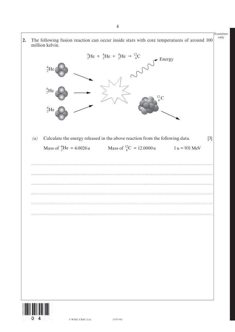
2. The following fusion reaction can occur inside stars with core temperatures of around 100 million kelvin.
© WJEC CBAC Ltd.
42
42
42
126
42
42
42
42
126
126He + He + He r C
He
He
He C
He
C
Energy
(a) Calculate the energy released in the above reaction from the following data. [3]
Mass of = 4.0026 u Mass of = 12.0000 u 1 u = 931 MeV

(1325-01) Turn over.
1325
0100
05
5Examiner
only (b) The isotope Ni has a binding energy per nucleon of 8.795 MeV/nucleon and this is the
highest known binding energy per nucleon. Calculate the mass of a Ni nucleus in unified atomic mass units (u) and give your
answer to 5 significant figures. [5]
mass of proton = 1.00728 u, mass of neutron = 1.00866 u, 1u = 931 MeV
© WJEC CBAC Ltd.
62 28
6228

6
(1325-01)
Examineronly
3. (a) A 131 nF capacitor is charged using a potential difference of 1.62 V. Calculate the charge stored by the capacitor. [2]
© WJEC CBAC Ltd.
(b) This 131 nF capacitor is then disconnected from the power supply and a large resistor connected across its terminals. As the capacitor discharges, the pd across it decreases from 1.62 V to 0.47 V in 220 ms. Calculate the resistance of the resistor. [4]
(1325-01) Turn over.
1325
0100
07
7Examiner
only (c) The plates of this 131 nF capacitor are square and are separated by 0.15 mm. Calculate
the length of a side of the capacitor plate. [3]
(d) In practice, how could the capacitance of this capacitor be increased by a factor of 100? [1]
© WJEC CBAC Ltd.
8
(1325-01)
Examineronly
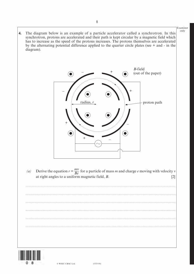
4. The diagram below is an example of a particle accelerator called a synchrotron. In this synchrotron, protons are accelerated and their path is kept circular by a magnetic field which has to increase as the speed of the protons increases. The protons themselves are accelerated by the alternating potential difference applied to the quarter circle plates (see + and - in the diagram).
© WJEC CBAC Ltd.
+
+
_
_
+
+
_
_
B-field(out of the paper)
proton pathradius, r
(a) Derive the equation r = for a particle of mass m and charge e moving with velocity v at right angles to a uniform magnetic field, B. [2]
mvBe
(1325-01) Turn over.
1325
0100
09
9Examiner
only
© WJEC CBAC Ltd.
(b) Use the equation r = to explain why the magnetic field must be increased as the speed of the protons increases. [2]
(c) Protons take 1.78 µs to complete a circuit of a synchrotron of radius 8.50 m. Calculate the strength of the magnetic field, B, required. [mproton = 1.67 × 10⁻²⁷ kg.] [4]
(d) (i) Modern synchrotrons use magnetic fields up to 10 T which cannot be produced using copper wires at room temperature. Explain why not, using B = µ0nI. [2]
(ii) Hence, explain why superconducting magnets are used to produce large magnetic fields in synchrotrons. [1]
mvBe
10
(1325-01)
Examineronly
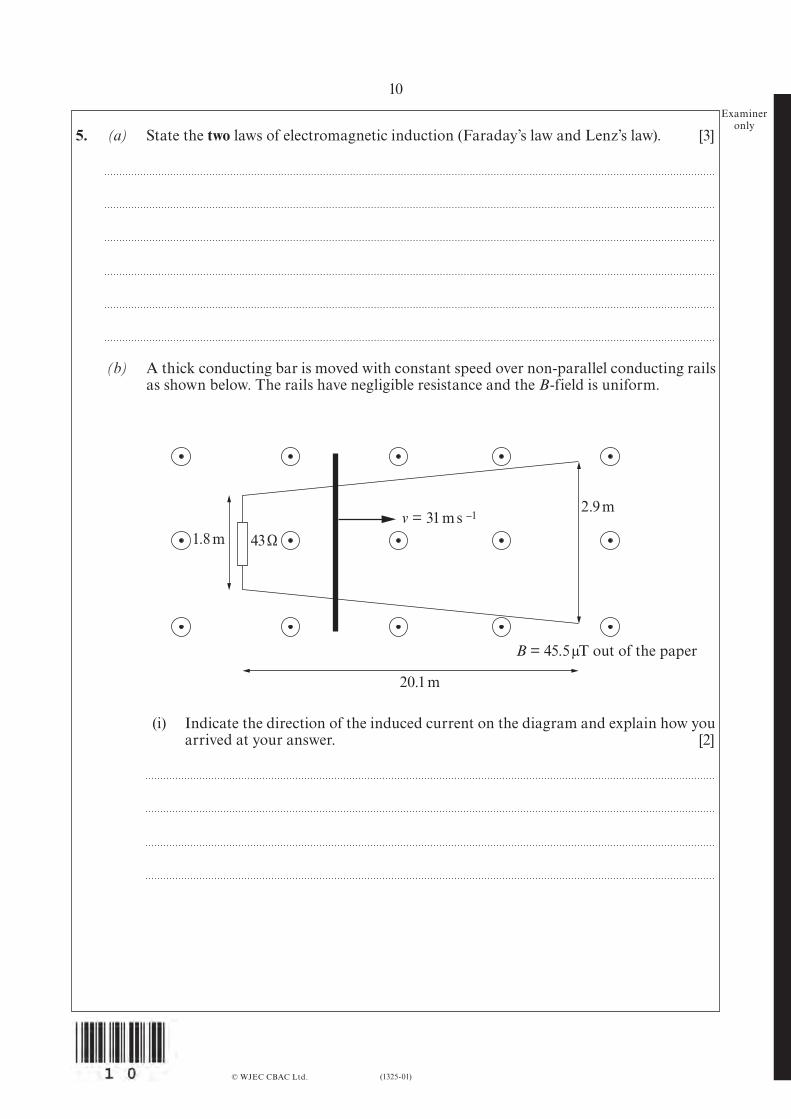
5. (a) State the two laws of electromagnetic induction (Faraday’s law and Lenz’s law). [3]
(b) A thick conducting bar is moved with constant speed over non-parallel conducting rails as shown below. The rails have negligible resistance and the B-field is uniform.
© WJEC CBAC Ltd.
2.9 m
20.1 m
1.8 m 43 Ωv = 31 m s –1
B = 45.5 µT out of the paper
(i) Indicate the direction of the induced current on the diagram and explain how you arrived at your answer. [2]

(1325-01) Turn over.
1325
0100
11
11Examiner
only (ii) The conductor moves at a constant speed of 31 m s–1. Use Faraday’s law to explain
why the induced emf increases. [2]
(iii) The conductor starts moving from the end near the 43 Ω resistor. Calculate the mean current in the resistor when the conducting bar has travelled the full 20.1 m length of the track. [4]
© WJEC CBAC Ltd.
12
(1325-01)
Examineronly
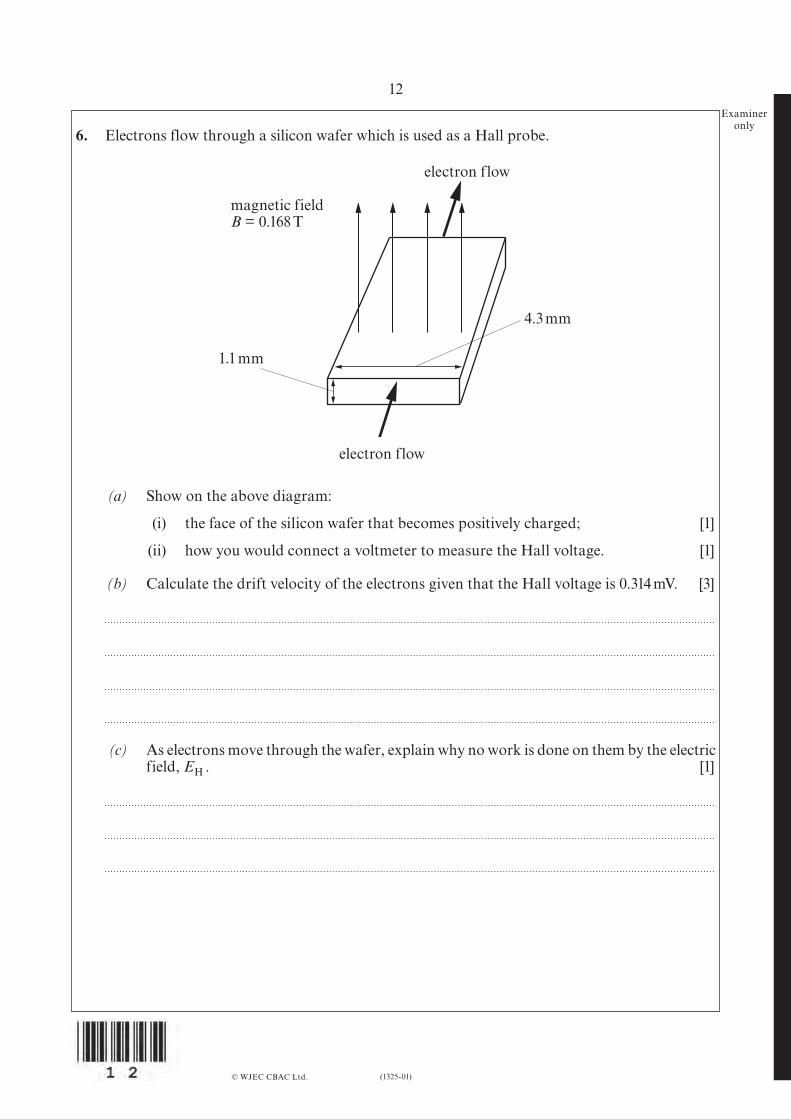
6. Electrons flow through a silicon wafer which is used as a Hall probe.
© WJEC CBAC Ltd.
electron flow
electron flow
4.3 mm
1.1 mm
magnetic fieldB = 0.168 T
(a) Show on the above diagram:
(i) the face of the silicon wafer that becomes positively charged; [1]
(ii) how you would connect a voltmeter to measure the Hall voltage. [1]
(b) Calculate the drift velocity of the electrons given that the Hall voltage is 0.314 mV. [3]
(c) As electrons move through the wafer, explain why no work is done on them by the electric field, EH . [1]

(1325-01) Turn over.
1325
0100
13
13Examiner
only (d) The current flowing in the silicon wafer is 0.38 A. Calculate the number of free electrons
per unit volume in the silicon wafer. [3]
© WJEC CBAC Ltd.
14
(1325-01)
Examineronly
SECTION B
The questions refer to the case study.Direct quotes from the original passage will not be awarded marks.
7. (a) In your own words and referring to diagram 2 in the case study, explain lift in terms of Newton’s laws. (See paragraph 3.) [2]
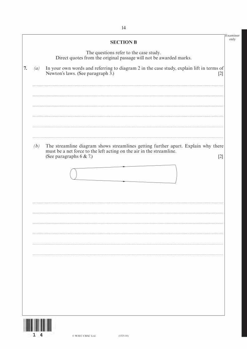
(b) The streamline diagram shows streamlines getting further apart. Explain why there must be a net force to the left acting on the air in the streamline.
(See paragraphs 6 & 7.) [2]
© WJEC CBAC Ltd.
(1325-01) Turn over.
1325
0100
15
15Examiner
only
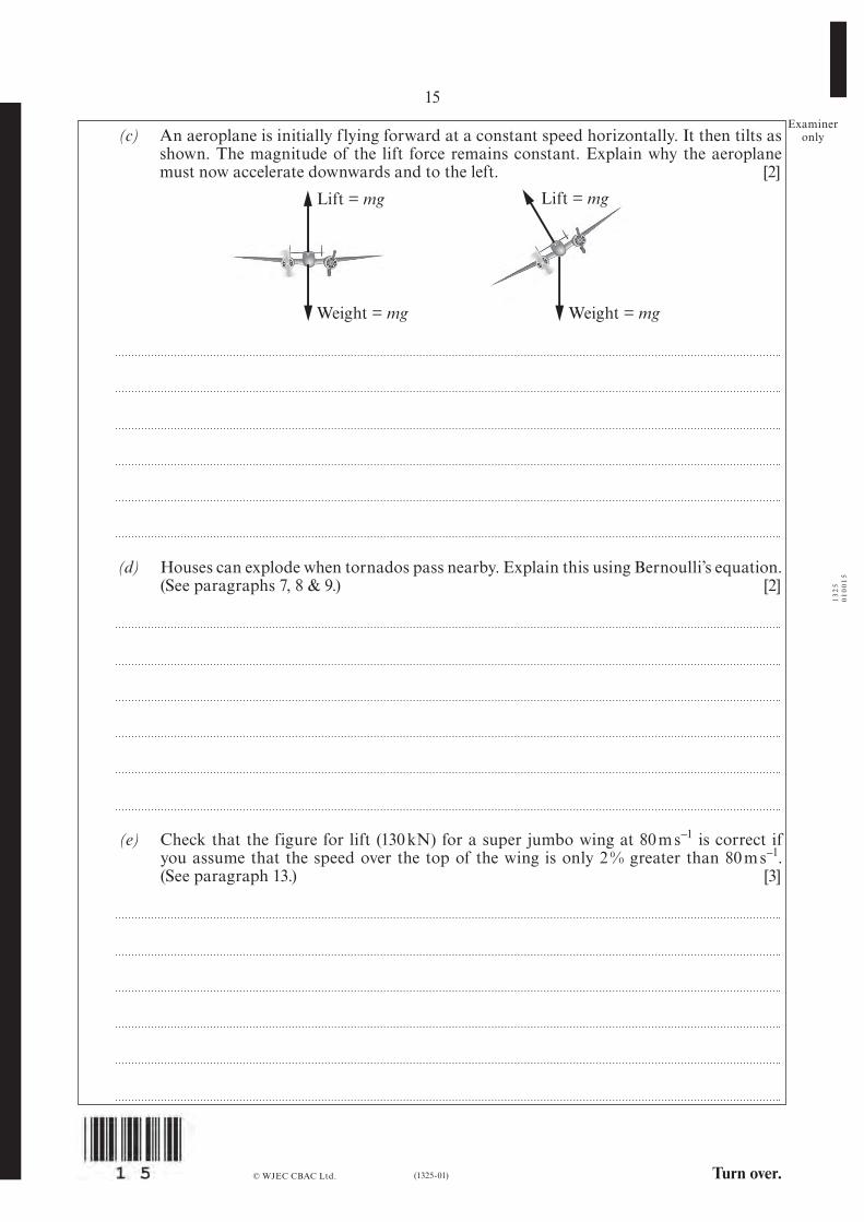
(d) Houses can explode when tornados pass nearby. Explain this using Bernoulli’s equation. (See paragraphs 7, 8 & 9.) [2]
(e) Check that the figure for lift (130 kN) for a super jumbo wing at 80 m s–1 is correct if you assume that the speed over the top of the wing is only 2 % greater than 80 m s–1.
(See paragraph 13.) [3]
© WJEC CBAC Ltd.
Weight = mg Weight = mg
Lift = mgLift = mg
(c) An aeroplane is initially flying forward at a constant speed horizontally. It then tilts as shown. The magnitude of the lift force remains constant. Explain why the aeroplane must now accelerate downwards and to the left. [2]
16
(1325-01)
Examineronly
(f) Show that the lift coefficient has no units. (See paragraph 17.) [3]
(g) Calculate the lift coefficient for an Airbus super jumbo at take-off. (See paragraph 17.) [2]
(h) Draw a labelled diagram of the set up that might be employed using a hair dryer, stand, clamp, protractor, digital balance and metal plate to measure lift coefficient against angle of attack. (See paragraphs 18 and 19.) [4]
© WJEC CBAC Ltd.

(1325-01)
17
© WJEC CBAC Ltd.
SECTION C: OPTIONAL TOPICS
Option A: Further Electromagnetism and Alternating Currents
Option B: Revolutions in Physics - The Newtonian Revolution
Option C: Materials
Option D: Biological Measurement and Medical Imaging
Option E: Energy Matters
Answer the question on one topic only.
Place a tick (√) in one of the boxes above, to show which topic you are answering.
You are advised to spend about 20 minutes on this section.
Turn over.
1325
0100
17
(1325-01)
18Examiner
onlyOption A: Further Electromagnetism and Alternating Currents
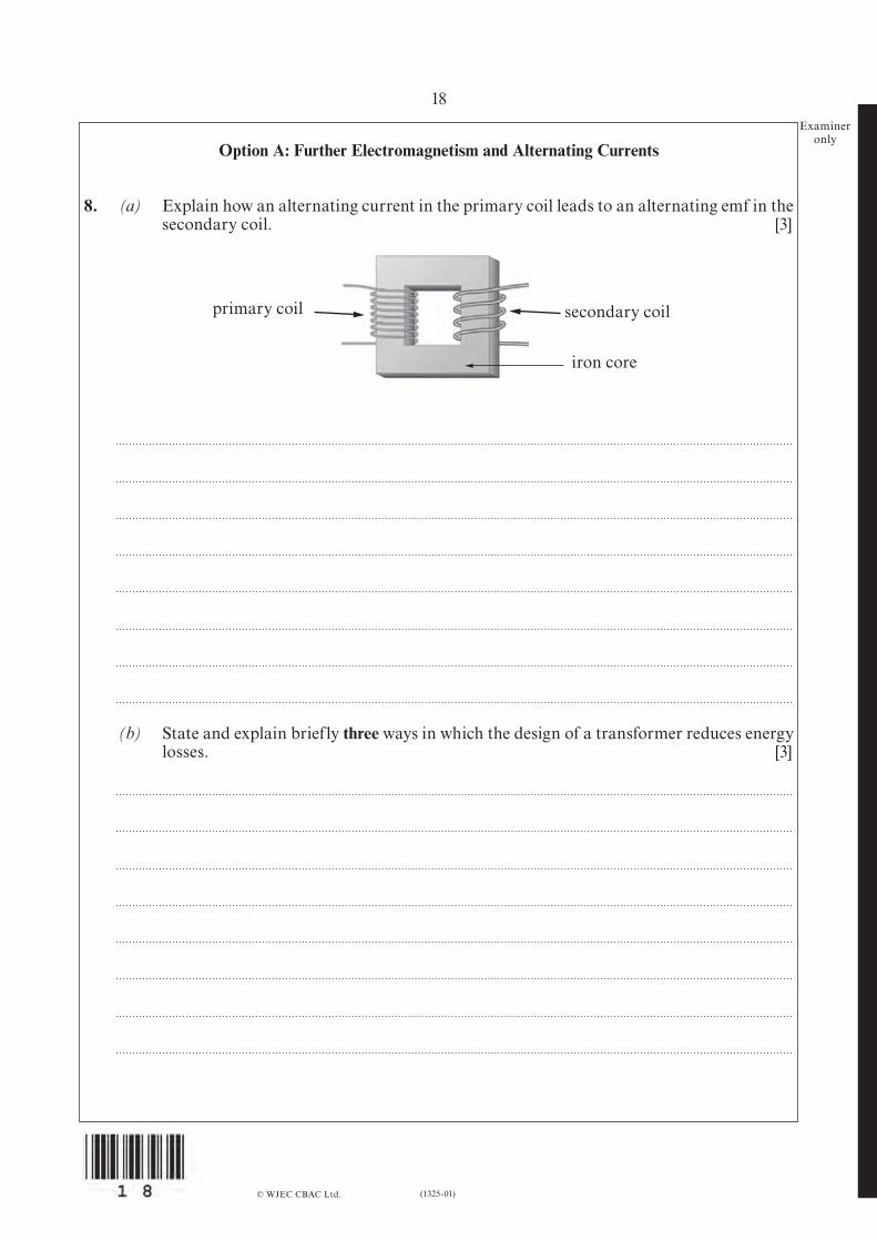
8. (a) Explain how an alternating current in the primary coil leads to an alternating emf in the secondary coil. [3]
© WJEC CBAC Ltd.
(b) State and explain briefly three ways in which the design of a transformer reduces energy losses. [3]
primary coil
iron core
secondary coil
Turn over.
19
(1325-01)
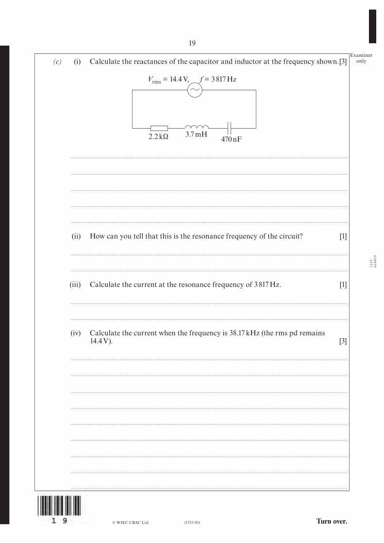
Examineronly (c) (i) Calculate the reactances of the capacitor and inductor at the frequency shown. [3]
© WJEC CBAC Ltd.
3.7 mH470 nF
f = 3 817 Hz
2.2 kΩ
(ii) How can you tell that this is the resonance frequency of the circuit? [1]
(iii) Calculate the current at the resonance frequency of 3 817 Hz. [1]
(iv) Calculate the current when the frequency is 38.17 kHz (the rms pd remains 14.4 V). [3]
1325
0100
19
Vrms = 14.4 V,
(1325-01)
20Examiner
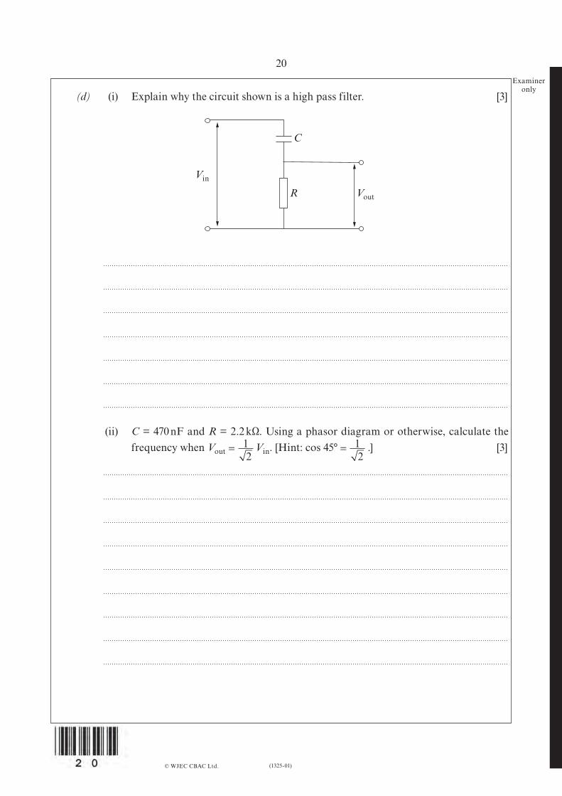
only (d) (i) Explain why the circuit shown is a high pass filter. [3]
© WJEC CBAC Ltd.
Vin
Vout
C
R
= 12
= 12
(ii) C = 470 nF and R = 2.2 kΩ. Using a phasor diagram or otherwise, calculate the frequency when Vout Vin. [Hint: cos 45° .] [3]
Turn over.
21
(1325-01)
Examineronly
Option B: Revolutions in Physics - The Newtonian Revolution
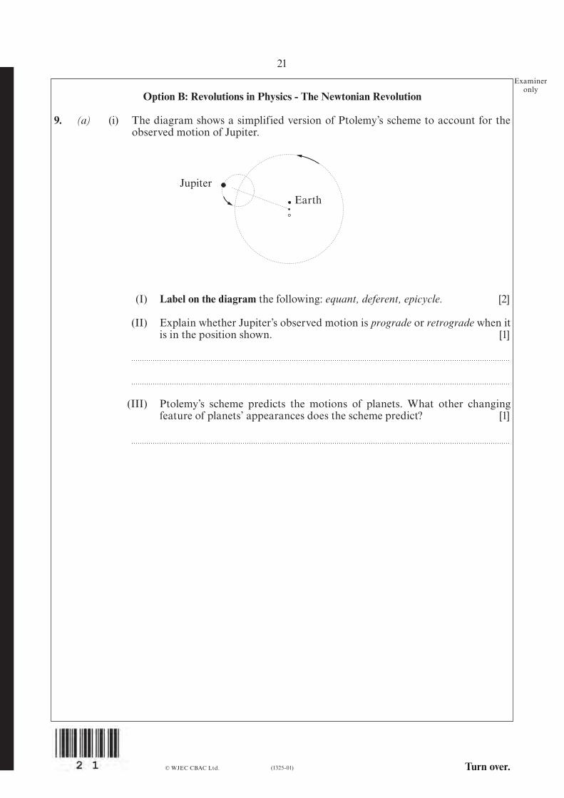
9. (a) (i) The diagram shows a simplified version of Ptolemy’s scheme to account for the observed motion of Jupiter.
© WJEC CBAC Ltd.
(I) Label on the diagram the following: equant, deferent, epicycle. [2]
(II) Explain whether Jupiter’s observed motion is prograde or retrograde when it is in the position shown. [1]
(III) Ptolemy’s scheme predicts the motions of planets. What other changing feature of planets’ appearances does the scheme predict? [1]
JupiterEarth
(1325-01)
22Examiner
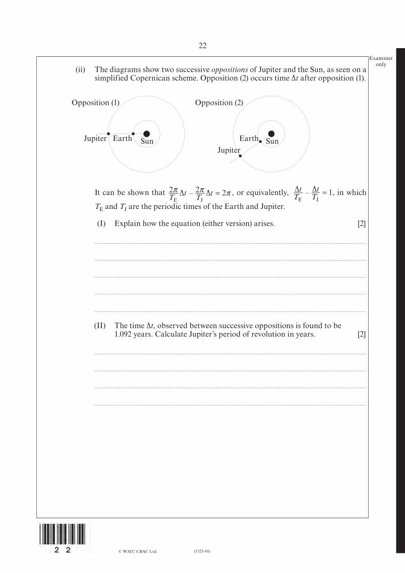
only (ii) The diagrams show two successive oppositions of Jupiter and the Sun, as seen on a
simplified Copernican scheme. Opposition (2) occurs time ∆t after opposition (1).
© WJEC CBAC Ltd.
It can be shown that , or equivalently, , in which
TE and TJ are the periodic times of the Earth and Jupiter.
(I) Explain how the equation (either version) arises. [2]
(II) The time ∆t, observed between successive oppositions is found to be 1.092 years. Calculate Jupiter’s period of revolution in years. [2]
2 2 2π π πT t T tE J∆ ∆– = ∆ ∆
E J
tT
tT– = 1
Opposition (1) Opposition (2)
JupiterJupiter
Earth EarthSun Sun
Turn over.(1325-01)
23Examiner
only
© WJEC CBAC Ltd.
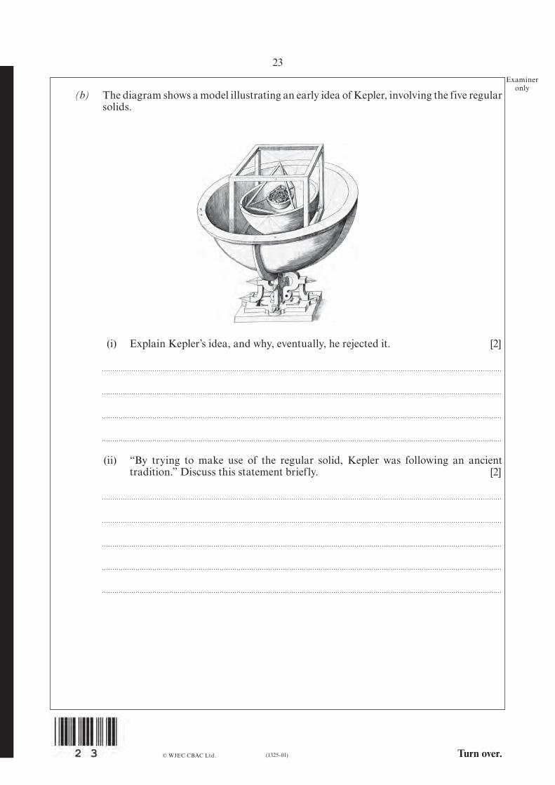
(b) The diagram shows a model illustrating an early idea of Kepler, involving the five regular solids.
(i) Explain Kepler’s idea, and why, eventually, he rejected it. [2]
(ii) “By trying to make use of the regular solid, Kepler was following an ancient tradition.” Discuss this statement briefly. [2]
(1325-01)
24Examiner
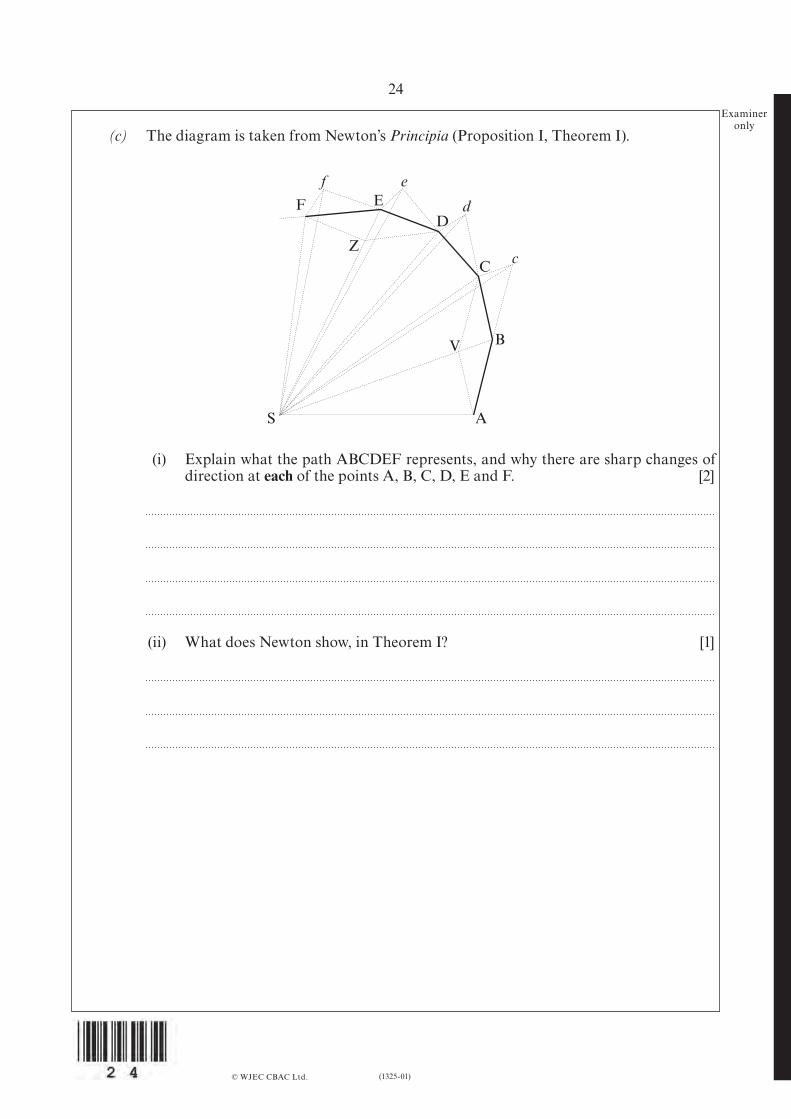
only (c) The diagram is taken from Newton’s Principia (Proposition I, Theorem I).
© WJEC CBAC Ltd.
(i) Explain what the path ABCDEF represents, and why there are sharp changes of direction at each of the points A, B, C, D, E and F. [2]
(ii) What does Newton show, in Theorem I? [1]
F
Z
V
S
f e
d
c
ED
C
B
A
Turn over.
25
(1325-01)
Examineronly
(d) The Moon’s mean orbital radius is 3.84 × 10⁸ m, and its period of revolution is 27.3 days. The Earth’s mean radius is 6.37 × 10⁶ m.
(i) Calculate the ratio: [2]
(ii) Show clearly that this supports an inverse square law of gravitation. [2]
(iii) What assumption are you making about the Earth’s mass distribution? [1]
© WJEC CBAC Ltd.
orbital acceleration of the Moonacceleration due to gravity on Earth’s surface
(1325-01)
26
Option C: Materials
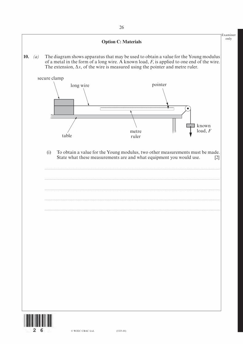
10. (a) The diagram shows apparatus that may be used to obtain a value for the Young modulus of a metal in the form of a long wire. A known load, F, is applied to one end of the wire. The extension, ∆x, of the wire is measured using the pointer and metre ruler.
© WJEC CBAC Ltd.
secure clamp
tablemetreruler
known load, F
long wire pointer
(i) To obtain a value for the Young modulus, two other measurements must be made. State what these measurements are and what equipment you would use. [2]
Examineronly
27
(1325-01)
Examineronly
© WJEC CBAC Ltd. Turn over.
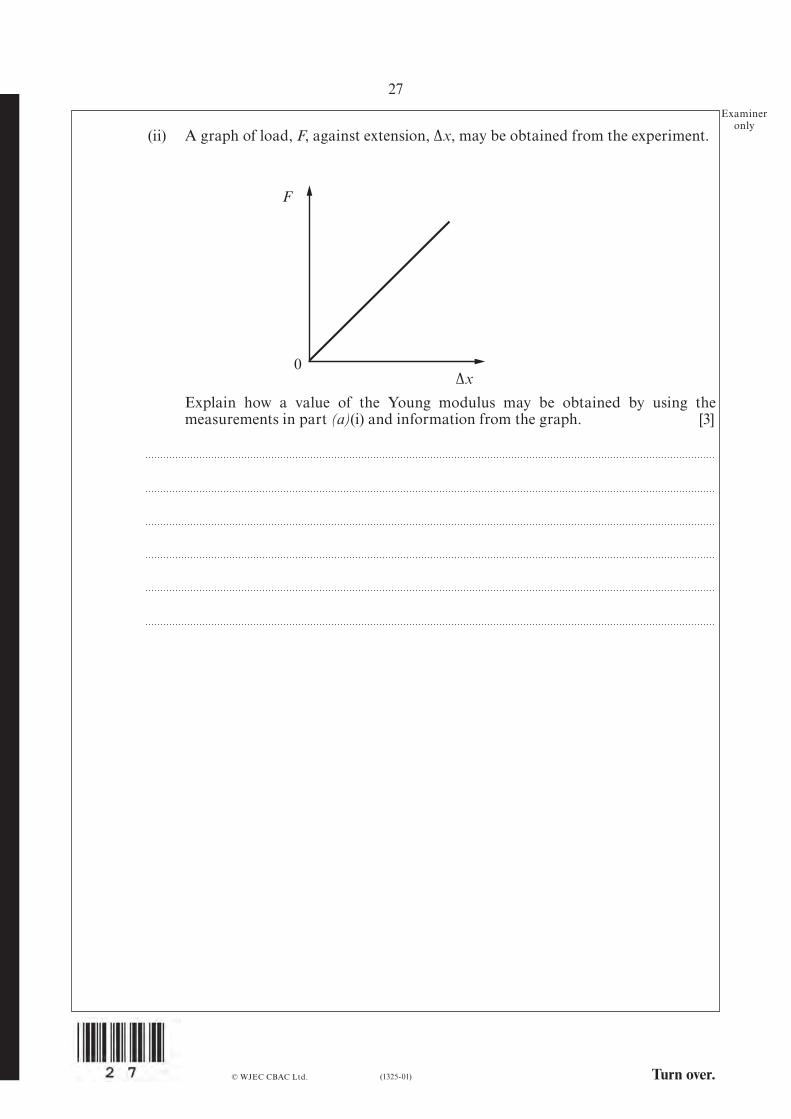
Explain how a value of the Young modulus may be obtained by using the measurements in part (a)(i) and information from the graph. [3]
F
0∆x
(ii) A graph of load, F, against extension, ∆x, may be obtained from the experiment.
28
(1325-01)
Examineronly
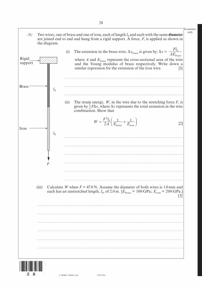
(b) Two wires, one of brass and one of iron, each of length l0 and each with the same diameter are joined end to end and hung from a rigid support. A force, F, is applied as shown in the diagram.
(i) The extension in the brass wire, ∆xbrass is given by: ∆x =
where A and Ebrass represent the cross-sectional area of the wire and the Young modulus of brass respectively. Write down a similar expression for the extension of the iron wire. [1]
(ii) The strain energy, W, in the wire due to the stretching force F, is given by F∆x, where ∆x represents the total extension in the wire combination. Show that
[2]
(iii) Calculate W when F = 47.0 N. Assume the diameter of both wires is 1.0 mm and each has an unstretched length, l0, of 2.0 m. [Ebrass = 100 GPa; Eiron = 200 GPa.]
[3]
© WJEC CBAC Ltd.
Fl0AEbrass
l0
l0
F
Iron
Brass
Rigid support
WF l
A E Ebrass iron= +
20
21 1
12
Turn over.(1325-01)
29Examiner
only (iv) Hence, or otherwise, determine the overall extension of the combination of wires
when F = 47.0 N. [1]
(v) Explain, using the Young moduli given, which of the two wires has undergone the greater extension and hence determine the ratio . [4]
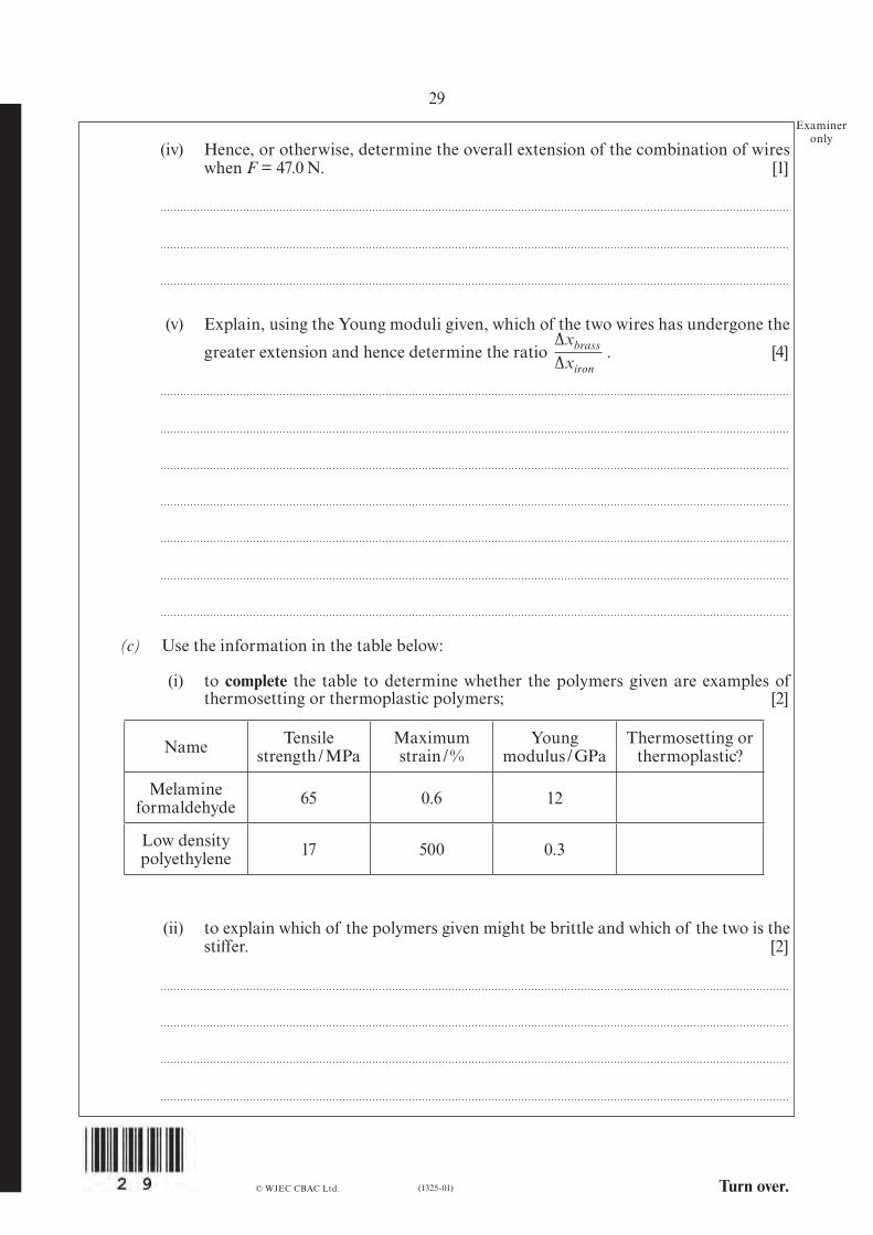
(c) Use the information in the table below:
(i) to complete the table to determine whether the polymers given are examples of thermosetting or thermoplastic polymers; [2]
© WJEC CBAC Ltd.
∆xbrass
∆xiron
Name Tensilestrength / MPa
Maximum strain / %
Young modulus / GPa
Thermosetting or thermoplastic?
Melamineformaldehyde 65 0.6 12
Low density polyethylene 17 500 0.3
(ii) to explain which of the polymers given might be brittle and which of the two is the stiffer. [2]
30
(1325-01)
Examineronly
Option D: Biological Measurement and Medical Imaging
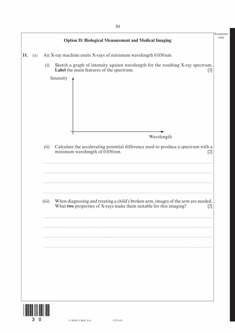
11. (a) An X-ray machine emits X-rays of minimum wavelength 0.030 nm.
(i) Sketch a graph of intensity against wavelength for the resulting X-ray spectrum. Label the main features of the spectrum. [3]
© WJEC CBAC Ltd.
Intensity
Wavelength
(ii) Calculate the accelerating potential difference used to produce a spectrum with a minimum wavelength of 0.030 nm. [2]
(iii) When diagnosing and treating a child’s broken arm, images of the arm are needed. What two properties of X-rays make them suitable for this imaging? [2]
Turn over.(1325-01)
31Examiner
only (iv) X-ray imaging is not suitable for revealing brain tumours. Which imaging technique should be used? Give reasons for your choice. [3]
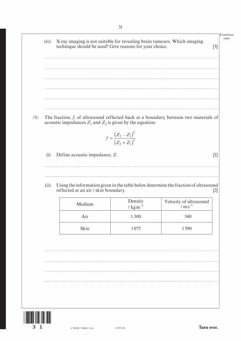
(b) The fraction, f, of ultrasound reflected back at a boundary between two materials of acoustic impedances Z1 and Z2 is given by the equation:
© WJEC CBAC Ltd.
fZ Z
Z Z=( )
+( )2 1
2
2 12
–
(i) Define acoustic impedance, Z. [1]
(ii) Using the information given in the table below determine the fraction of ultrasound reflected at an air / skin boundary. [2]
Medium Density / kg m–3
Velocity of ultrasound/ m s–1
Air 1.300 340
Skin 1 075 1 590
32
(1325-01)
Examineronly
(iii) Explain the importance of your answer to (b)(ii) and state what ultrasound radiographers must do to obtain clear images of the body. [2]
(c) (i) Explain the difference between radiation exposure and absorbed dose. [2]
(ii) Explain why, for the same absorbed dose, the dose equivalent would be different for exposure to alpha particles than for gamma rays. [3]
© WJEC CBAC Ltd.
Turn over.
33
(1325-01)
Examineronly
Option E: Energy Matters
12. A new nuclear reactor has been proposed based on the reaction of lithium-7 and a proton to produce two -particles.
p + Li r Be r He + He + 17.1 MeV
Although this is not a new nuclear reaction (it was the original splitting the atom experiment in 1932), there have been some theoretical developments that suggest this might be a useful reaction.
The above reaction is produced by ionising hydrogen and accelerating the resulting protons in a vacuum to an energy of around 300 keV. Unfortunately, in the past, only one in 30 million protons accelerated to the correct voltage have produced this nuclear reaction.
(a) (i) The above reaction is produced by accelerating ionised hydrogen with 300 kV. Explain two possible benefits of the system compared with fission reactors. [4]
(ii) Calculate the energy required to accelerate 30 million protons to an energy of 300 keV and explain why the above reaction does not seem profitable. [3]
© WJEC CBAC Ltd.
α11
73
84
42
42
(1325-01)
34Examiner
only (iii) There is around 1016 kg of Li in the world’s oceans and the mass of Li can be
taken as 7 u. Calculate the number of Li atoms in the world’s oceans. [2]
(iv) The total annual world energy consumption is around 5 × 10²⁰ J. Assuming that each Li atom can, ideally, provide an energy of 17.1 MeV, calculate the number of years Li could supply the world’s energy consumption. [3]
© WJEC CBAC Ltd.
73
73
73 7
3
73
Turn over.
35
(1325-01)
Examineronly
© WJEC CBAC Ltd.
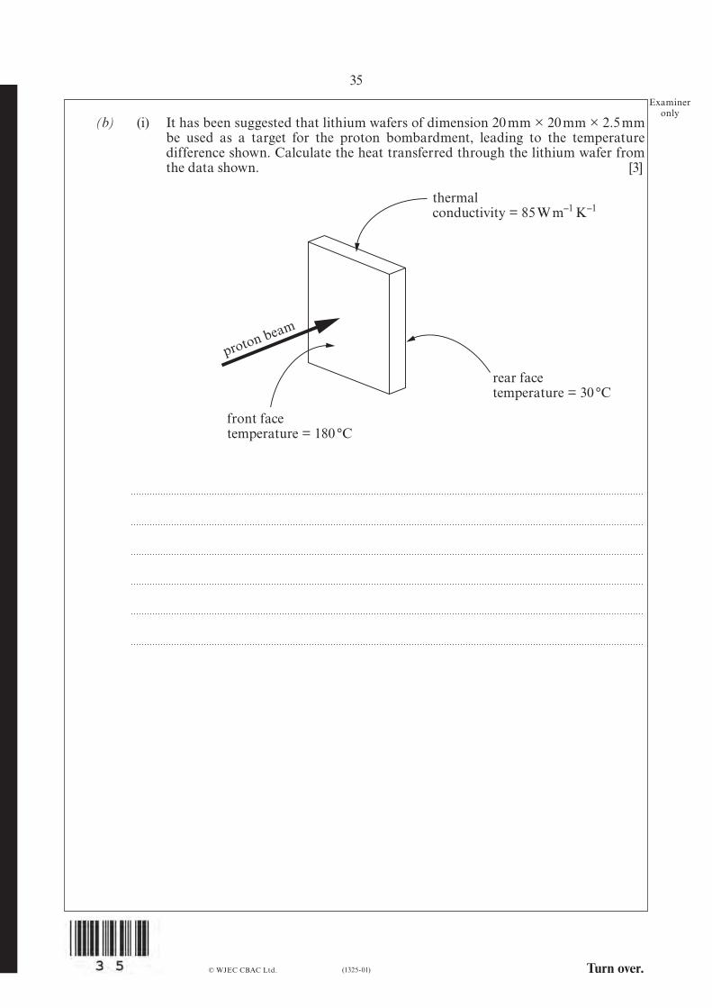
(b) (i) It has been suggested that lithium wafers of dimension 20 mm × 20 mm × 2.5 mm be used as a target for the proton bombardment, leading to the temperature
difference shown. Calculate the heat transferred through the lithium wafer from the data shown. [3]
proton beam
thermalconductivity = 85 W m–1 K–1
front facetemperature = 180 °C
rear facetemperature = 30 °C
(1325-01)
36Examiner
only (ii) The heat transferred through the lithium wafer is used to raise the temperature of
a flowing gas. By sending this gas quickly through a compressor, its temperature can be raised dramatically. Explain why the temperature of the gas increases using the first law of thermodynamics. [2]
(iii) Eventually, water will be boiled to produce superheated steam to drive turbines and generators. Explain why superheated steam at 500 °C leads to greater efficiencies than steam at 100 °C. [3]
END OF PAPER
© WJEC CBAC Ltd.

(1325-01) Turn over.
37
Examineronly
Questionnumber
Additional page, if required.Write the question numbers in the left-hand margin.
© WJEC CBAC Ltd.

Questionnumber
Additional page, if required.Write the question numbers in the left-hand margin.
Examineronly
(1325-01)
38
© WJEC CBAC Ltd.
1325
01B
001
JD*(S13-1325-01B)© WJEC CBAC Ltd.
GCE A level
1325/01-B
PHYSICSASSESSMENT UNIT PH5
A.M. THURSDAY, 20 June 2013
CASE STUDY FOR USE WITH SECTION B
Examination copyTo be given out at the start of the examination.The pre-release copy must not be used.
2
(1325-01B)
From Newton, through Bernoulli to Super Jumbos – an explanation of lift
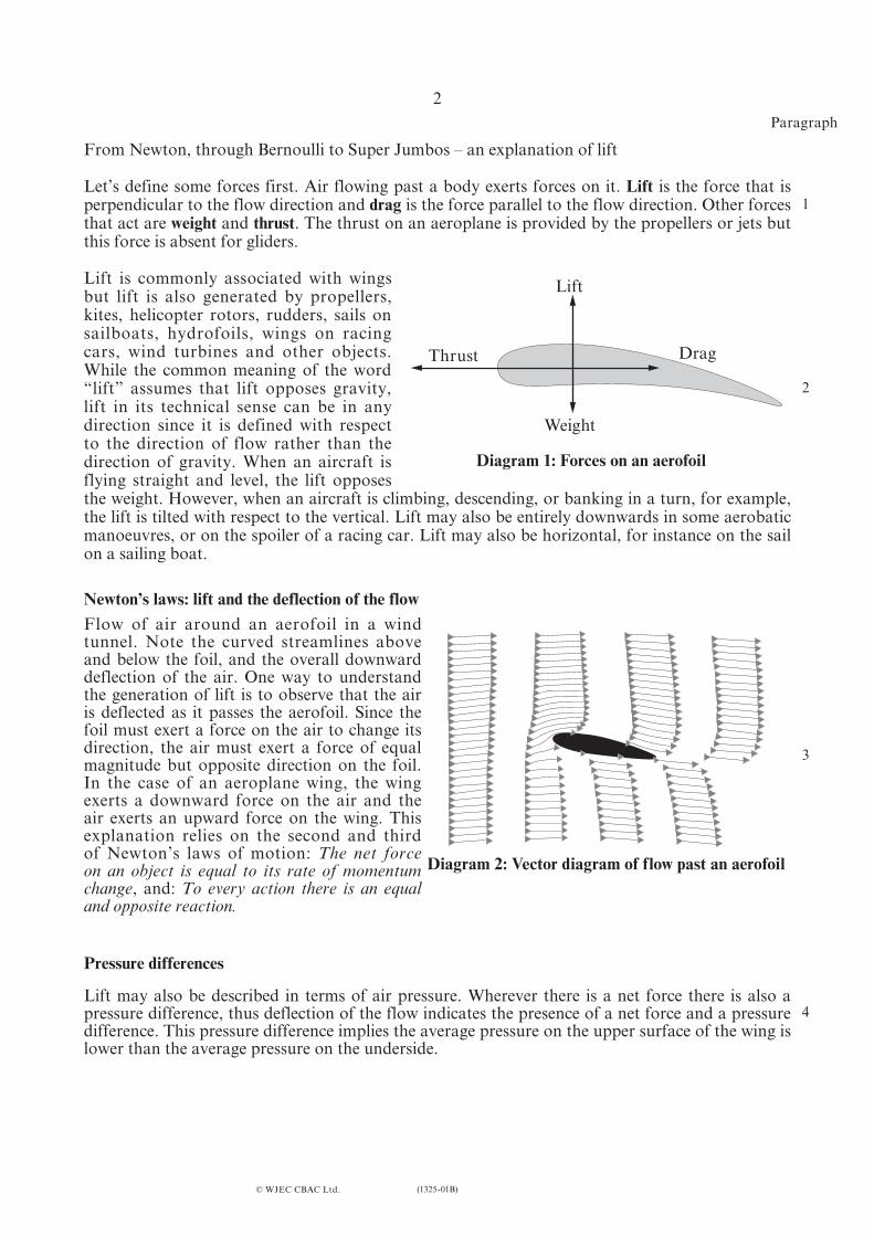
Let’s define some forces first. Air flowing past a body exerts forces on it. Lift is the force that is perpendicular to the flow direction and drag is the force parallel to the flow direction. Other forces that act are weight and thrust. The thrust on an aeroplane is provided by the propellers or jets but this force is absent for gliders.
Lift is commonly associated with wings but lift is also generated by propellers, kites, helicopter rotors, rudders, sails on sailboats, hydrofoils, wings on racing cars, wind turbines and other objects. While the common meaning of the word “lift” assumes that lift opposes gravity, lift in its technical sense can be in any direction since it is defined with respect to the direction of flow rather than the direction of gravity. When an aircraft is flying straight and level, the lift opposes the weight. However, when an aircraft is climbing, descending, or banking in a turn, for example, the lift is tilted with respect to the vertical. Lift may also be entirely downwards in some aerobatic manoeuvres, or on the spoiler of a racing car. Lift may also be horizontal, for instance on the sail on a sailing boat.
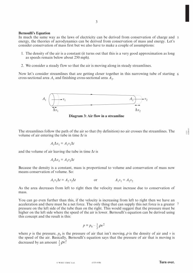
Newton’s laws: lift and the deflection of the flowFlow of air around an aerofoil in a wind tunnel. Note the curved streamlines above and below the foil, and the overall downward deflection of the air. One way to understand the generation of lift is to observe that the air is deflected as it passes the aerofoil. Since the foil must exert a force on the air to change its direction, the air must exert a force of equal magnitude but opposite direction on the foil. In the case of an aeroplane wing, the wing exerts a downward force on the air and the air exerts an upward force on the wing. This explanation relies on the second and third of Newton’s laws of motion: The net force on an object is equal to its rate of momentum change, and: To every action there is an equal and opposite reaction.
Pressure differences
Lift may also be described in terms of air pressure. Wherever there is a net force there is also a pressure difference, thus deflection of the flow indicates the presence of a net force and a pressure difference. This pressure difference implies the average pressure on the upper surface of the wing is lower than the average pressure on the underside.
© WJEC CBAC Ltd.
Paragraph
1
2
3
4
Diagram 1: Forces on an aerofoil
Diagram 2: Vector diagram of flow past an aerofoil
Lift
Thrust Drag
Weight
(1325-01B) Turn over.
1325
01B
003
3
Bernoulli’s EquationIn much the same way as the laws of electricity can be derived from conservation of charge and energy, the theories of aerodynamics can be derived from conservation of mass and energy. Let’s consider conservation of mass first but we also have to make a couple of assumptions:
1. The density of the air is a constant (it turns out that this is a very good approximation as long as speeds remain below about 250 mph).
2. We consider a steady flow so that the air is moving along in steady streamlines.
Now let’s consider streamlines that are getting closer together in this narrowing tube of starting cross-sectional area A1 and finishing cross-sectional area A2.
© WJEC CBAC Ltd.
5
6
7
The streamlines follow the path of the air so that (by definition) no air crosses the streamlines. The volume of air entering the tube in time ∆t is
A1∆x1 = A1v1∆t
and the volume of air leaving the tube in time ∆t is
A2∆x2 = A2v2∆t
Because the density is a constant, mass is proportional to volume and conservation of mass now means conservation of volume. So:
A1v1∆t = A2 v2∆t or A1v1 = A2v2
As the area decreases from left to right then the velocity must increase due to conservation of mass.
You can go even further than this, if the velocity is increasing from left to right then we have an acceleration and there must be a net force. The only thing that can supply this net force is a greater pressure on the left side of the tube than on the right. This would suggest that the pressure must be higher on the left side where the speed of the air is lower. Bernoulli’s equation can be derived using this concept and the result is this:
p = p0 –
where p is the pressure, p0 is the pressure of air that isn’t moving, is the density of air and v is the speed of the air. Basically, Bernoulli’s equation says that the pressure of air that is moving isdecreased by an amount .
Diagram 3: Air flow in a streamline
12
2ρv
12
2ρv
A1 v1 A2 v2
∆x1 ∆x2
ρ
4
(1325-01B)
There are many things that can be explained using Bernoulli’s equation but here’s a little explanation of one of the most annoying aerodynamic effects of all. Consider a person taking a shower with a light shower curtain. Which way does the shower curtain move?
To use Bernoulli’s equation you need some idea of the speed of the air. Outside the shower, the air should be stationary (unless you live in a draughty house) but inside the shower, the water droplets are causing the air to move slightly. According to Bernoulli’s equation, the pressure inside the shower will be lower so that the net force on the shower curtain is inward. There you are - an explanation of why that irritating cold and wet shower curtain always creeps spookily inwards towards you.
Explaining lift using BernoulliThe diagram to the left represents the same flow past a wing as the previous vector diagram (diagram 2). The horizontal gaps between the dots in the diagram represent equal intervals of time. Note that the spaces between the dark dots are much bigger at the upper surface than at the lower surface. This means that the speed of the flow is far greater over the top of the wing than over the bottom. Hence, applying Bernoulli’s equation explains why the above wing experiences lift.
Diagram 4 is great for explaining lift using Bernoulli’s equation but it also debunks the old explanation of lift which went like this: • whentheair splits togoaboveandbelowthewing, theairpassingabovethewingtakes
exactly the same time to reach the back of the wing as the air passing underneath, • thetopsideofthewingisdesignedtobelongerthanthebottom, • soairtravelsquickeroverthetopofthewing, • Bernoulliexplainswhythepressurebelowisbiggerthanaboveandhencelift.
One look at diagram 4 should dismiss the first point of the old argument. Also, if the old explanation was complete: 1. how can an aeroplane fly when the top of the wing is only 2% longer than the bottom? 2. how can an aeroplane fly upside down?
To get an idea of the first point, an Airbus super jumbo takes off at a speed of 80 m s–1 in air of density 1.2 kg m–3. Its wings are made in Broughton, North Wales and have an enormous area of around 850 m2. If you assume that the speed over the top of the wing is 2% larger, this gives a total lift force of 130 kN. This may sound impressive until you realise that the mass of an empty super jumbo is around 300 tonnes. The truth is that although the top side of the wing is only 2% longer than the bottom, the increase in speed can be more than 50% over the top side of the wing.
The second point is answered by considering the angle of attack ( ) of the wing because this is also important in deflecting the airflow.
© WJEC CBAC Ltd.
Diagram 4: Flow past an aerofoil showing time intervals
8
9
10
11
12
13
14θ
(1325-01B) Turn over.
5
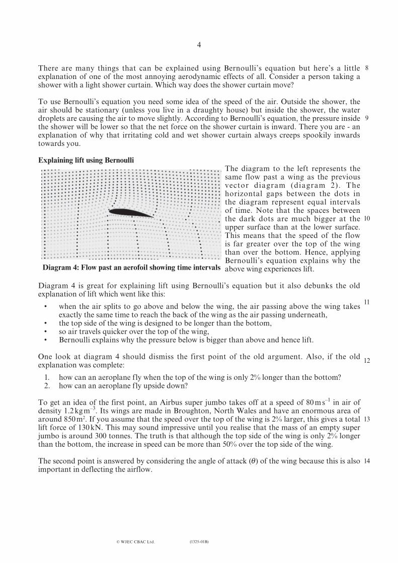
Lift due to an angle of attackThe aerofoil shown to the left is symmetrical – the top and bottom of the aerofoil are the same (the wings of aerobatic planes are designed to be like this so that they fly equally well upside down). In order to produce lift, the wings have to be tilted to produce the same flow as in diagrams 2 & 4.
(angle of attack)
© WJEC CBAC Ltd.
θ
Diagram 5
An aeroplane flying upside down can still have an angle of attack and produce lift.
Lift coefficientThe lift force provided by a wing can be calculated as a function of speed with the following equation:
where• L is lift force,• is air density,• v is air speed,• A is the area of the wing, and• CL is the lift coefficient of the wing (dependent on the angle of attack).
L v ACL= 12
2ρ
15
16
17
ρ
upperlower
6
(1325-01B)
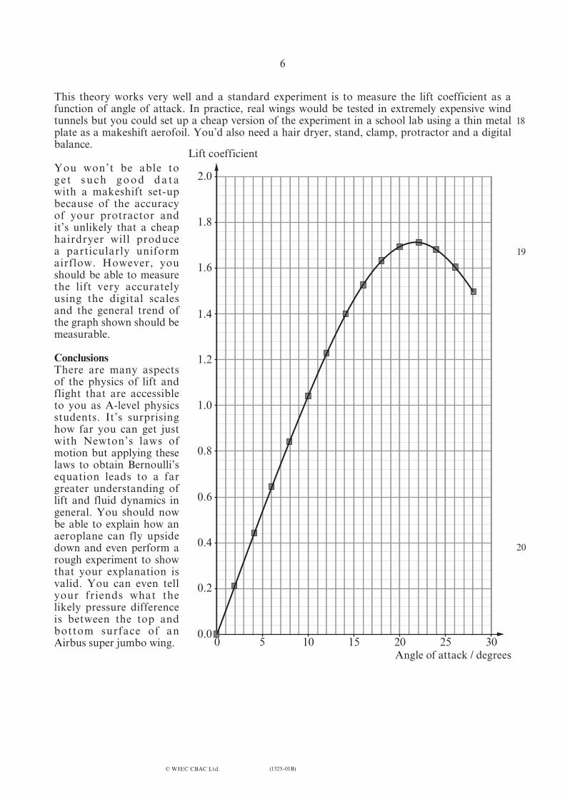
This theory works very well and a standard experiment is to measure the lift coefficient as a function of angle of attack. In practice, real wings would be tested in extremely expensive wind tunnels but you could set up a cheap version of the experiment in a school lab using a thin metal plate as a makeshift aerofoil. You’d also need a hair dryer, stand, clamp, protractor and a digital balance.
You won’t be able to g e t s u c h g o o d d a t a with a makeshift set-up because of the accuracy of your protractor and it’s unlikely that a cheap hairdryer will produce a particularly uniform airflow. However, you should be able to measure the lift very accurately using the digital scales and the general trend of the graph shown should be measurable.
ConclusionsThere are many aspects of the physics of lift and flight that are accessible to you as A-level physics students. It’s surprising how far you can get just with Newton’s laws of motion but applying these laws to obtain Bernoulli’s equation leads to a far greater understanding of lift and fluid dynamics in general. You should now be able to explain how an aeroplane can fly upside down and even perform a rough experiment to show that your explanation is valid. You can even tell your friends what the likely pressure difference is between the top and bottom surface of an Airbus super jumbo wing.
© WJEC CBAC Ltd.
00.0
0.2
0.4
0.6
0.8
1.0
1.2
1.4
1.6
1.8
2.0
5 10 15 20 25 30Angle of attack / degrees
Lift coefficient
18
19
20

![ASSESSMENT UNIT PH5: ELECTROMAGNETISM, NUCLEI & … · 2018. 6. 26. · Calculate the rms value of the induced emf. [1]..... (ii) State the value of the rate of change of flux through](https://img.pdfslide.net/doc/110x75/60e5dc684759b402544bd779/assessment-unit-ph5-electromagnetism-nuclei-2018-6-26-calculate-the.jpg)


![ASSESSMENT UNIT PH5: ELECTROMAGNETISM, … 2012 QP... · Show that its decay constant is 7.6 × 10⁻¹⁰ s–1. [2] 90 ... has 3400 turns per unit length and its turns have a ... are](https://img.pdfslide.net/doc/110x75/5a9f6e1a7f8b9a71178cc13d/assessment-unit-ph5-electromagnetism-2012-qpshow-that-its-decay-constant.jpg)