Embed Size (px)
Citation preview
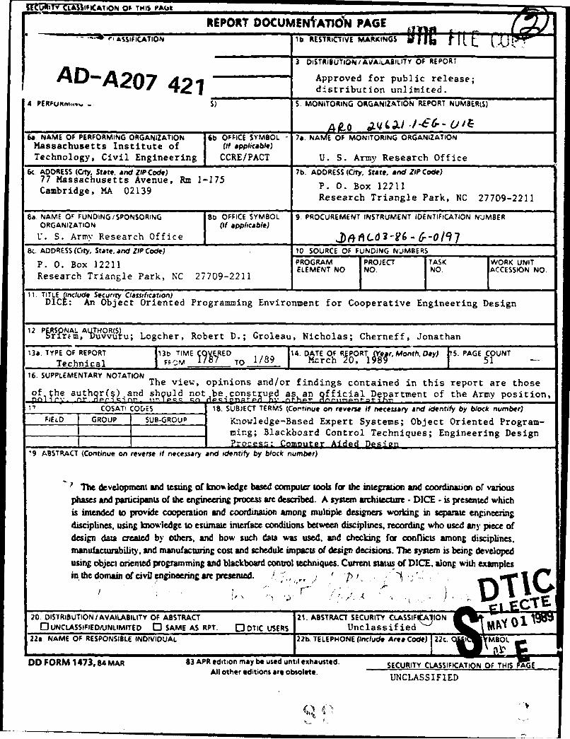
SECURITY CLASSIIICAYBON 0; TNIS 10A~t
REPORT DOCUMEN ATION -PAGE'ASSIFICATION ib. RESTRICTIVE MARKINGS&IIl
F ~3 DISTRIBUTION,/AVAILAILITY OF REPORT
A D Approved for public release;-A 20 421distribution unlimited.
4 PERFUev~.... -. S) S OIOIGOGNZTO EOTNME
60 NAME OF PERFORMING ORGANIZATION 6b OFFICE SYMBOL 7a. NA~vEO MONITORING ORGANIZATIONMassachusetts Institute of (if applicable)Technology, Civil Engineering CCRE/PACT U. S. Army Research Office
6c. ADDRESS (City, State. and ZIP Code) I7b. ADDRESS (City, State, and ZIP Code)77 Massachusetts Avenue, Rm 1-175 P. 0. Box 12211Cambridge, MA 02139 Research Triangle Park, NC 27709-2211
Ba. NAMVE OF FUNDING /SPONSORING SoB OFFICE SYMBOL 9. PROCUREMENT INSTRUMENT IDENTIFICATION NUMBERORGANIZATION (if applicable)
V. S. Army Research Office ______ f~CO 1 rO9Sr. ADDRESS (City, State, and ZIP Code) .10 SOURCE OF FUNDING NUMBERS
P. 0. Box 12211 PROGRAM IPROJECT ITASK ~ WORK UNIT
Research Triangle Park, NC 27709-2211 ELMN NO oIO CESO O
ll. TITLE (include Security Classification)DICE: An Object Oriented Programming Environment for Cooperative Engineering Design
r2 r vuu Logcher, Robert D.; Groleau, Nicholas; Cherneff, Jonathan
l3a. TYPE OF REPORT 89 IM 9~,E 14. DATE OF RfPORT CreMnh a) S. PAGE COUNTTechnical FFI -TO 1/8 Mcrch 0 .g, 8h9Dy)1 51-
16.SUPLEENAR 70ATONThe view, opinions and/or findings contained in this report are thoseofthe authr($).and sh uld not be~const ugd as an ffAcialj De teto h rypsition,
COSATI CODES 18. SUBJECT TERMS (Com'inue on reverse if necessary and identify by block number)FIELD GROUP T SUB-GRtOUP Kmowledge-Based Expert Systems; Object Oriented Program-
ming; Blackboard Control Techniques; Engineering DesignProcess: Computer Aided Design
19 ABSTRACT (Continue on reverse if necessary and identify by block number)
?The development and testing of kw%% ledge based computer tools for the iegraic and coo ditnaoi or variousphases and participant~s of the engineering process aWe described.. A system architecture - DICE - is presented whichis intended to provide cooperation and coordiatio among multiple designers working in separate engineringdisciplines, using knowledge to estimate interface conditions between disciplines, recording who used any, piece ofdesign data created by others, and bow such data was used, and checking for conflicts among disciplines,manufacturability. and manufacturing cost and schedule impacts of design decisions. The system is being developedusing object oriented programming and blackboard control techniques. Current status of DICE, along with examples
in the domain of civil enginerng are presented.7"
UNCAISSRIIN/UVALIITD OFA ABSC 21 ASTRACT SECURITY CLASSIFrA11ON
20. DISTIBUTION/VAILABIITYD OFAM ABSRT QDTIC USERtS Unclassified 122s, NAME OF RESPONSIBLE INDIVIDUAL 22b. TELEPHONE (include Area Code)22. MBOL
DD FORM 1473, 84 MAR 83 APR edition may be used until exhausted. SECURITY CLASSIFICATION OF TH S AEAll other editions are obsolete. UNCLASSI FIED
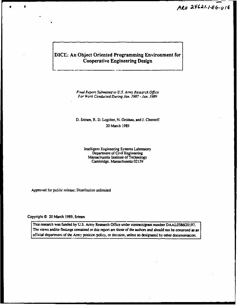
DICE: An Object Oriented Programming Environment forL Cooperative Engineering Design
Final Report Submitted to U.S. Army Research OfficeFor Work Cordi~aed During Jan. 1987 - Jan. 1989
D. Sriram, R. D. Logcher. N. Groleau, and J. Cherneff20 March 1989
Intelligent Engineering Systems LaboratoryDepartment of Civil Engineering
Massachusetts Institute of TechnologyCambridge, Massachusetts 02139
Approved for public release: Distribution unlimited
Copyright © 20 March 1989, Sriram
Table of Contents1 Introduction 12 Scope of Work 33 Background $
3.1 Relevant Computer-Bas ' Technologies 53.2 Negotiation Theory 73.3 Relevant Systems 6
3.3.1 CAE Systems 83.3.2 Computer-Aided Negotiation 10
4 A Framework for A Distributed and Integrated Environment for Computer-Aided 12Engineering
4.1 Overview of DICE 124.2 Control Mechanism 124.3 Blackboard: Global Database 18
4.3.1 Coordination Blackboard Partition 184.3.2 Solution Blackboard Partition 184.3.3 Neogotiation Blackboard Partition 20
4.4 Knowledge Modules 214.5 The Negotiation Activity 23
5Current Status 245.1 Graphic Definition of Objects 245.2 Blackboard Transactions 305.3 A Simulation 335.4 BUILDER in DICE 41
6 Summary and Future Work 417 Bibliography 46
Accession For
NTSGRA&IDTIC TABUnannouncedJustificatio 7
0 0 PV
Dy~Distribution/ 6
Availability Codes
Aa and/orDist Speoil
Al .

List of FiguresFigure 1: A Simplified View of a Distributed Design Environment 5Figure 2: A Conceptual View of DICE for Design and Construction 14Figure 3" Evaluation and Propagation of Implications 16Figure 4: The Constraint Negotiation Process 17Figure 5: The Blackboard 18Figure 6: Different Planes in the SBB 19Figure 7: The Designer's Goal Hierarchy 25Figure 8: The Fabricator's Goal Hierarchy 26Figure 9: The Connected Rods Solution 27Figure 10: The Split Connections Solution 28Figure 11: Displaying a Class 28Figure 12: Unking a Class to its Superclass 29Figure 13: Creation of Slots 29Figure 14: Creation of Facets 30Figure 15: Display of the Object Hierarchy 31Figure 16: Posting Information to the Blackboard 32Figure 17: Retrieving Information From the Blackboard 32Figure 18: Set up for Simulation of the Hyatt Regency Design Problem 34Figure 19: Set up for Simulation of the Hyatt Regency Design Problem (Ctd.) 35Figure 20: Simulation 36Figure 21: Simulation (Continued) 37Figure 22: Simulation (Continued) 38Figure 23: Simulation (Continued) 39Figure 24: Simulation (Completed) 40Figure 25: Schematic View of BUILDER 42Figure 26: Overview of DICEY-BUILDER 43Figure 27: Posting From KM to Blackboard: Translation Process 44Figure 28: Representative Objects 45

List of TablesTable 1: Tasks involved in the Design of a Tall Building 3
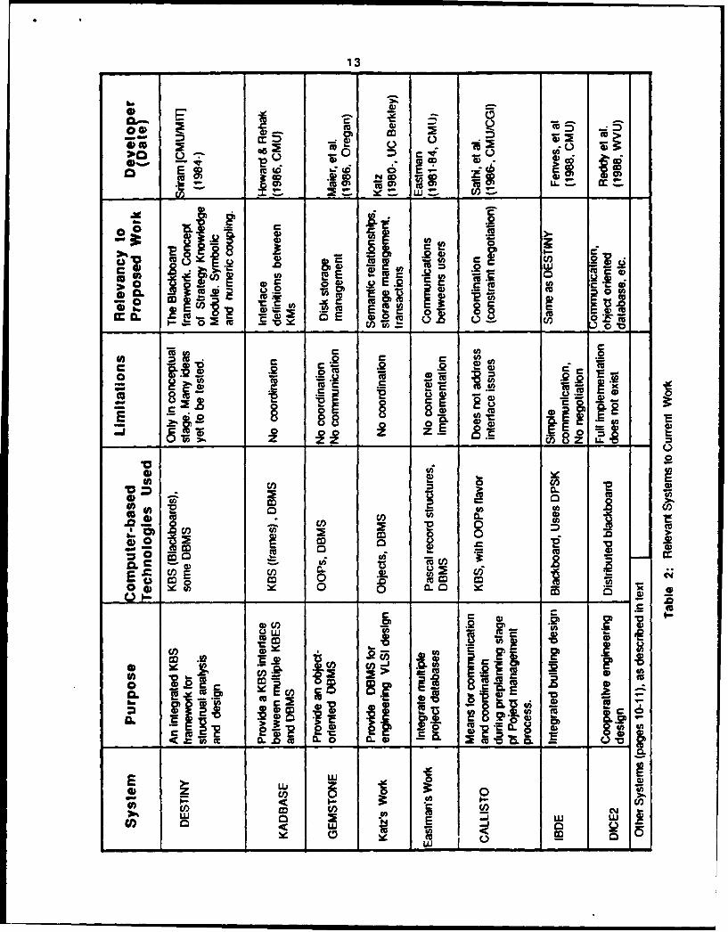
Table 2: Relevant Systems to Current Work 13

DICE: An Object Oriented Programming Environment forCooperative Engineering Design
AbstractThe development and testing of knowledge based computer tools for the integration and coordination of various
phases and participants of the engiaieering process are described. A system architecture - DICE - is presented whichis intended to provide cooperation and coordination among multiple designers working in separate engineeringdisciplines, using knowledge to estimate interface conditions between disciplines, recording who used any piece ofdesign data created by others, and how such dat was used, and checking for conflicts among disciplines,manufacturability. and manufacturing cost and schedule impacts of design decisions. The system is being developedusing object oriented programming and blackboard control techniques. Current status of DICE, along with examplesin the domain of civil engineering are presented.
1 IntroductionOn July 17, 1981, two skywalks in the lobby of the Hyau Regency Hotel in Kansas City collapsed. It was cited as
the "most devastating structural collapse ever to take place in the United States"; 114 people died and 186 wereinjured [24). This was not only a failure of a physical structural system, but also a failure of the process by whichmost projects in the U. S. are designed and built. The objective our current research is to provide computer basedtools which would help during design and construction to avoid errors of the type made in Kansas City.
The Hyatt failure was attributed to a combination of three events. First. in progressing from the preliminary todetailed design, where joint and connection detailing occurs, the design of the hanger to spandrel beam connectionwas inadequate. Second, in developing shop drawings, the connection detail was changed by the steel fabricator,thereby "compounding an already critical condition." Third, this second error was not caught during approvalchecking of the shop drawings by the struc'mral engineers. These were all errors of communication anc coordinationin the design process, errors caused by the structure of the process, lack of tools used in this process, and focus ondocumenting the product of design while neglecting "process" and "intent" documentation. These problems alsoexist in other engineering application areas.
Large engineering projects involve a large number of components and the interaction of multiple technologies.The components included in the product are decided in an iterative design process. In each iteration, interfaces andinterface conditions among these components are designed with slack to account for potential variations createdwhen the components and interface values become better known. Iteration proceeds towards increasing detail;design personnel may change, and their numbers expand with increasing level of detail.
The problems facing the engineering industry in the U. S. will be highlighted by considering the design andconstruction1 of structures. On a single project, interacting design technologies often come from separate firms orfunctional groups within a firm, and there is little coordination between designers and contractor(s) during design.Because designers find coordination among themselves difficult, they leave this task to construction managers or thecontractor. Thus, working drawings, use.: to inform the contractor of the product, lack detail. Shop or fabricationdrawings are required from the contractor to document details, but potential conflicts among trades are oftenunrecognized until construction begins. Several undesirable effects are caused by this lack of coordination.
3Mma.ufacwuring in the civil engineering industry is known as coartructsi. There are several differences between the cmttruction industry andthe manufacturing industry. For example, in manufacturing several hundreds of a single type of product art produced, wt,ereas censutactminvolves the productin of one-.-kind products. However, the ovenl engineering process is similar. In this paper the terms manufacturmg mdcmstrUucaon will be used to dent the reatWwn or cretion oft de signed anact.
2
1. The consmttion process is slowed, work stops when a conflict is found.
2. Prefabrication opportunities are limited, because details must remain flexible.
3. Opportunities for automation are limited, because capital intensive high speed equipment isincompatible with work interruptions from field recognized conflicts.
4. Rework is rampant, because field recognized conflicts often require design and field changes.
5. Conservatism prevades design, because designers provide excessive slack in component interface., toavoid conflicL
6. The industry is unprepared for the advent of automated construction, as the need for experience indesign limits choice to available materials placed by hand.
All of these problems decrease productivity. In addition, failures, such as the Hyatt collapse, occur more often thenthey should. Overcoming these problems requires significant changes to the design process, together with superiorcompter integrated design and construction/manufacturing (CIDCAM) tools. Those tools must be tailored to theneeds of designers who are [2]:
"constantly engaged in searching out various consequences of design decisions [especially those made by others]"
This paper details the development of a prototype system to test new concepts for computer tools to integratevarious stages involved in the engineering of a product. The major objectives of this system are to:
1. Facilitate effective coordination and communication in various disciplines involved in engineering.
2. Capture the process by which individual designers make decisions, that is, what information was used,how it was used and what did it create.
3. Forecast the impact of design decisions on manufacturing or construction.
4. Provide designers interactively with detailed manufacturing process or construction planning.
5. Develop intelligent interfaces for automation.
Computer aided tools, which will be collectively called DICE (Distributed and Integrated environment forComputer-aided Engineering), are being currently developed to address the above objectives. DICE willsignificantly improve productivity by,.
" reducing error in design;
" providing more detailed design;
" providing better manufacturing or construction planning;
" allowing easier recognition of design and manufacturing (construction) problems;
" using manufacturability criteria throughout design; and
" advancing automation.
Lessons from the Hyatt failure show that such tools are required. Had the connection designer had access to theconcepts of load transmission underlying the preliminary design, local buckling might have been recognized and thejoint details changed. Had the fabricator preparing the shop drawings had access to that information, he would haveseen that his change violated the purpose of the connection scheme. Had the shop drawing checker seen all thesechanges together with their intent, he would have recognized the faults in the design.
The engineering design process and problems associated with this process are described in Section 2. Using this
2Engineers from several industries that we visited felt that computer aided tods for cooperation and coordination can gready incrnse their-rodu-wit.
I
3
background, an overview of DICE is given. Background material on computer-based technologies used in this workand systems relevant to the current work are presented in Sections 3. A system architecture which utilizes conceptsfrom knowledge-based systems and database management systems is described in Section 4. This is followed by a
description of the current status of DICE.
2 Scope of WorkThe problems that engineers normally solve fall along the derivaton-formatwn specmm [1]. In derivation-type
problems, solutions consist of identifying an outcome or hypothesis from a finite set of ouComes known to the
problem solver. By contrast, in formation-type problems, the problem solver has only the knowledge of how to
form the solution. A variety of problem solving techniques are invoked to arrive at a solution.
Design and manufacturing (or construction planning) problems fall at the formation end of this spectrum. Designand manufacturing are accomplished by a team of engineers, each knowledgeable in a particular aspect of theproblem, but with little knowledge of the decision processes of others. Each could be considered as one of manysources of knowledge, and hence, design and manufacturing (construction) could be viewed as a process ofconstructing an artifact which satisfies constraints from many sources by using knowledge which also comes frommany sources. The extent of interactions can be seen by looking at the diverse set tasks, listed in Table 1, that mustbe performed by a diverse set of professionals during the design, for example, for a high rise building [303.
Planning Architectural designSpatial layout Site planningPreliminary structural design Analysis modelingComponent design Geometric modelingSubstructure design Cost estimatingElectrical distribution design Elect. distribution analysisMechanical design Mechanical analysisHVAC design I-VAC analysisVertical transportation design Regulatory complianceVarious design critics Fire safety analysis
Table 1: Tasks involved in the Design of a Tall Building
As CAD/CAE becomes more widespread, each of these consultants will be performing increased amount of theirwork with computer tools, tools which will embody and use their knowledge in their speciality area.
From this view, the stages of design and construction might be described as3 :1. Problem Identification. The problem, necessary resources, target technology, etc., are identified at
this stage.
2. Specification Generation. Design requirements and performance specifications are listed.
3. Concept Generation. The selection or synthesis of potential design solutions, such as a structuralsystem, is performed. Several alternative designs may be generated.
4. Analysis. The response of the system to external effects is determined by using the appropriate modelfor the system.
5. Evaluation. Solutions generated during the Concept Generation stage are evaluated for consistencywith respect to the specifications. If several designs are feasible then (normally) an appropriateevaluation function is used to determine the best possible design to refine further.
3Similar "aes occur in the manufaerinr industry.
4
6. Detailed Design. Various components of the system ae refined so that all applicable constraints (orspecifications) are satisfied.
7. Design Review. The detailed design is checked for global consistency.
8. Construction. This :-.volves the preparation of shop drawings, development of detailed constructionschedules, actual construction, and construction monitoring.
There may be significant deviations between the properties of components assumed or generated at the ConceptGeneration stage and those determined at the Detailed Design stage, which would necessitate a reanalysis. Theprocess continues until a satisfactory or optimal design is obtained.
During each stage in this process, representatives from the various interacting disciplines meet and discuss
potential interactions between the components they envision designing. They use estimates of space needs,structural, heat, and electrical loads, and other factors to set requirements for their systems based on the needs ofothers. Experience is used to estimate these interfaces. Explanations on how these estimates were determined isseldom sought, except where they cause conflicts between objectives. When individual designers select componentsand systems during any stage of design, they use and try to develop solutions which satisfy the interface estimates.
The problem with this process is that individual designers often lack sufficient experience in both estimating theirinterfaces (assessing their impact on others) and in asking for information needed from others. They assume,instead, situations similar to other designs. Similarly, they seldom think about and may even lack knowledge of
constructability or management and control of the construction process. This may lead to incompatible componentselection and poor choice of design parameters. For example, the use of wide rooms in low cost housing is
incompatible with inexpensive construction techniques. The designer is assumed in this process to have sufficientknowledge of construction techniques, materials, and equipment to make proper decisions. This is seldom the case.Also, since the present design process does not document reasons behind decisions, others cannot easily questiondecisions or improve designs. DICE's framework was developed to obviate the above problems. A simplified viewof DICE is shown in Figure 1, where users within their discipline interact with individual CAD tools and KBS forcomponent design and solution generation. These systems automatically communicate with a global system whichprovides data and support facilities.
An initial (prototype) version of DICE operates on two SUN workstations. The final system will operate onseveral interacting computers, which will be high speed workstations with good knowledge representation tools.Knowledge representations for support facilities are required to:
1. Estimate and negotiate interface parameters between stages of design, doing so in an interactivemanner, when a designer asks for information (i.e., if a designer asks for information that has not yetbeen developed, knowledge will be used to estimate values);
2. Keep track of who used design information, when, and whether it was estimated or actual values (sothat when values change, the design can remain coordinated);
3. Use coded individual knowledge sources to assist in or automate component design, retainingcomponent information about sources of data used in the design, the algorithms or knowledge used,and inputs on design rationale from the user,
4. Operate numerous background processes to check design choices for interferences, violations ofinterface assumptions, constructability, and cost and schedule impacts;
5. Allow user input and design alterations from either a commercial CAD system or the knowledgerepresentation workstation; and
6. Inform designers of the impacts of initial designs and changes by others on their design choices.We extend the simplified version of DICE, shown ir. Figure 1, to address the above issues in Section 4.

Architect HVAC Designer Structural Fabricator
Figure 1: A Simplified View of a Distrbuted Design Environment
3 BackgroundThere are five technologies are required to realize DICE: Artificial Intelligence (knowledge-based systems, object
oriented programming, negotiation theory, etc.), Distributed Databases, Local Area Networks, DeisgnMethodologies (design for assembly. Taguchi's methods, house of quality, hierarchical design models), and VisualComputing (geometric reasoning and user interfaces). In the next section, we will describe some of the computer-based technologies that are utilized in the current DICE prototype. This is followed by a summary of work onnegotiation. A review of relevant research work is provided in Section 3.3.
3.1 Relevant Computer-Based Technologies
Developments in computer science and engineering methodologies have provided engineers with a variety ofsoftware development tools. The computer-based software development tools that are relevant to this project are:
1. Object Oriented Programming (00P) Methodologies;2. Knowledge based systems (KBoS)c
3. Database management systems (DBMS);4. Visual computing, and5. Local area networks.
Object Oriented Programming. Object Oriented Programming (00?) is a style of programming that involvesthe use of objects and messages. Objects are defined by Stefik and Bobrow as [37]:
Objects aen entities that combine the properties of procedres and data since they pefom computations md save ockastle.
Objects contain slots and slots may consist of a number of facets. A slot may simply be an aribute or it may be arelation. The facets contain meta-information about the slo l
Al actions in object oriented programming are performed through messages. Messages tell the object what to doand not how to do at. Methods are attached to the object to execute the actions associated with the messages. The

6
message passing ability in OOP supports the concept of data abstraction.
Objects can be grouped into "classes," where each class of objects knows how to perform several actions.Individual instances of objects can be created from a parucular class. The Object Oriented programmer builds asystem by specifying new classes of objects and their associated methods. Most OOP systems support the conceptof "inheritance," where a class of objects may be specified as a "subclass" of another "superclass" of objects.Subclasses and instances inherit methods from their superclass, and am usually mor specific entities than their(usually) more general superclass. An object may inherit methods and data from multiple classes through a networkof srucutral relationships. In short, every object has the ability to: sore information, process information, creasenew buformation, and communicate with other objects. Ths OOP facilitates encoding design and constructionknowledge in a disaggregated and modular form.
As an example consider the following object
BEAM-1instance: "Beam"M :Methods: Display-moment, Calcul.ate-moment
The message (send beam-] calculate-moment), where beam-I is the object to which the message is addressed,would compute the moment in accordance with the Calculate-moment method. For further details about objectoriented programming see [37].
Knowledge-based systems. KBS are computer programs which incorporate knowledge and reason through theapplication of their knowledge to data about a specific problem. If these systems incorporate human expertise thenthey are called knowledge-based expert systems (KBES) 4. A typical KBES consists of three components:Knowledge-base, Context, and Inference Mechanism or Control Mechanism. Several problem solving architecturesused in the Inference Mechanism are described in [36].
In this work, a knowledge-based framework - the Blackboard architecture - that facilitates the integration ofdiverse sources of knowledge is used [16]. In addition, the work on truth maintenance systems will also be utilized[9, 101.
The Blackboard architecture provides a framework for. 1) integrating knowledge from several sources, and 2)representing multiple levels of problem decomposition. It uses two basic strategies [25]: 1) divide and conquer, and2) opportunistic problem solving. The divide and conquer strategy is realized by decomposing the context, which iscalled a Blackboard, into several levels depicting the problem solution decomposition, while opportunistic problemsolving is achieved by focusing on the parts of the problem that seem promising. The Blackboard architecture hasbeen successfully used in solving a wide range of tasks, such as speech recognition [12], signal processing [26],and planning [16].
Database management systems. Engineers have always dealt with large amounts of data in diverse applications.Hence, storing and manipulating data forms an integral part of the engineering process. Database managementsystems (DBMS) provide means to store large amounts of data in databases for use by a variety of applications. Dataaccess is controlled through a dictionary so that individual programs need not be changed when the database
"For the pupose of this raper, the term KBS and KBES wil be used intermhangeably.

7
stucture changes. If a problem requires the integration of several geographically distributed databases then we enter
the realm of distributed databases. A system that manages these distributed databases is termed as a distributed
database management system (DDMS). There are several issues that arise in the development of a DDMS:
concurrency control, query processing, reliability, efficiency, etc. (See [3,7,27] for further discussion of these
issues).
Visual Computing. Engineers make extensive use of diagrams (images) to convey their ideas. They also like to
see scientific information (or data) to be conveyed by visual diagrams (images). Hence computer-based systems for
engineering should have the ability to: 1) recognize and understand diagrams, and 2) generate diagrams. The study
and development of the methodologies required to provide above capabilities in a computer program falls under the
realm of Visual Languages. Visual languages can be classified into: 1) Visual Information Processing Languages
(VIPL), and 2) Visual Programming Languages (VPL) [4). In VIPL, the objects that are displayed on the screen (by
the engineer) have inherent visual meaning, i.e., the object has some semantic meaning associated with it. The task
here is to map these objects into their semantic content. An example of VIPL is spatial reasoning about engineering
objects. On the other hand in VPL, the visual diagrams are generated on the screen from scientific (or otherwise)
data and it is left to the engineer to extract the semantic meaning of these diagrams, e.g., current work on solid
modelling. It is also important to realize that these visual languages should be portable. Hence, they should be
developed in an environment that is portable across a variety of hardware, such as the X Window system, which is
rapidly gaining acceptance as an industry standard.
3.2 Negotiation TheoryNegotiation is a process by which a joint decision is made by two or more parties. The parties first verbalize
contradictory demands and then move toward agreement by a process of concession making or search for new
alternatives. The parties can range in size and importance from children trying to decide how to divide up a set of
toys to nations trying to end a w.,r (which might not be as different as it seems once you really think about it).
Irrespective of the size and the type of the parties involved, there seems to be a general body of principles that areapplicable to address the negotiation problem. Pruitt's approaches to the negotiation problem has considerablerelevancy for DICE [28).
Pruitt's Princliples of Negotiation. Two basic principles of negotiation - the goal/expectation hypothesis and
the strategic choice model - are presented in [28].1. The goal/expectation hypothesis states that for most forms of coordinative behavior to be enacted, it is
necessary to have both a goal of achieving coordination and some degree of trust in the other party'sreadiness for coordination.
2. The strategic choice model postulates three basic strategies for moving toward agreement: unilateralconcession; competitive behavior, and coordinative behavior. These are assumed to be at leastpartially mutually exclusive. Hence, tradeoffs among them can be expected. Conditions thatdiscourage the use of one strategy should encourage the use of the others and vice versa.
Since negotiation itself can be viewed as a form of coordination, the theory of how coordination develops provides
insight into the conditions under which negotiation begins.
Coordination. Coordination occurs when bargainers work together in search of a mutually acceptableagreement. Without the possibility of coordination, negotiation would often take an inordinate amount of time,create much psychological strain, end in disagreement, and/or poison future relations between the participants.
Coordination is very common, especially in the later stages of negotiation, when competitive behavior no longerseems very productive. According to Pruitt., two main types of coordination occur in negotiation [28]:
1. Concession exchange, in which the parties move toward one another on a single dimension or swapconcessions on different dimensions; this is a form of compromise bargaining.

2. Problem-solving &scussions, in which the parties share information about goals and priorities insearch of an option that will satisfy both parties' needs, that is, an integrative agreement.
For further background on negotiation theory see [15].
3.3 Relevant SystemsThe following systems, developed in recent years, address home of the capabilities needed for DICE 5. However,
these systems do not address the problem from a global perspective. Further, full scale implementations of many of
these systems do not yet eXiSL
3.3.1 CAE SystemsThe following systems have been developed for computer aided engineering.
The DARPA Initiative in Concurrent Engineering (DICE). The primary goal of DICE26 is the development
of an advanced design and engineering environment that facilitates rapid prototyping of electro-mechanical partsand high-density eectronic assemblies [29]. In DICE2, each workstation is connected to the DICE2Communication Channel (DCC) through which all information flows, with the help of a Concurrency Manager
(CM). Each workstation has a Local Concurrency Manager (LCM). LCM coordinates the flow of Info-Paks(extended NFS-Network File Servers) with the CM to provide transparency. In addition, the workstation also has alocal database (LDB) and a set of analysis and support tools, with isolated interfaces. Using, the LCM, LDB and thetools, a domain expert will be able to access remote data, perform computations and communicate the results toothers in the network. The LCM will also be used to access External Networks and remote Compute Servers.
Conclusions drawn from local analysis are used to influence design by asserting decision parameters on aBlackboard. A Knowledge Server (KS) is used to retrieve generic information such as that which may be found in a
handbook, or transformed information from the Pan-Process Organization (POP) database. The simulatedProduction Facility (SPF) at one end of the DCC i.; a multi-level simulator that may be used by productionengineers, plant designers and others to validate producibility before designs are finalized. The Advanced
Prototyping center (APC), at the other end of the DCC, consists of programmable machine tools which may be usedto produce actual prototypes prior to production runs at the pilot plant level.
DICE2 is still in a development stage and is yet to be demonstrated on a real world problem. If successfullyimplemented, this system should provide answers to most of the problems stated here. It is interesting to note thatDICE and DICE2 have many similar characteristics.
An Integrated Software Environment for Building Design and Construction (IBDE). Fenves et al.
developed an integrated environment - called IBDE (Integrated Building Design Environment) - of processes andinformation flows for the vertical integration of architectural design, structural design and analysis and constructionplanning [13]. The integrated environment makes use of a number of Al techniques. The processes are implemented
as KBES. A Blackboard architecture is used to coordinate communication between processes. The globalinformation shared among the processes is hierarchically organized in an Object Oriented Programming language.
The Integrated Building Design Environment (IBDE) system is implemented in the form of five verticallyintegrated Knowledge-Based processes:
1. An architectural planner (ARCHPLAN).
'In addition, a reent summary of sorne of the work in computer aided coopeaive work appeared in 121].
Fw the make of prevewting onfusion, this systan will be referred to as DICE2 und not as DICE.

9
2. A preliminary structural designer (Hn-RISE).3. A component designer (SPEX).4. A foundation desirner (FOOTER).5. A construction planner (CONSTRUCTION PLANEX).
The processes communicate with each other in two ways:1. a message Blackboard is used to communicate project status information such as whether a process is
ready to execute, has successfully performed its task or has encountered a failure, and
2. a project database used for storing the information generated and used by the processes
A controller uses the information posted on the Blackboard to initiate the execution of individual processes. The
controller also directs the data manager to provide and receive the information shared between the processes. Sincethe different processes may reside on different machines, the data manager and the Blackboard rely on a local area
communication network.
DESTINY. DESTINY is a knowledge-based framework developed for integrating all stages of the structuraldesign process [34]. It consists of several Knowledge Modules (KMs) that communicate through a Blackboard.The Blackboard consists of several levels that define the abstraction hierarchy of objects. The entities generated atvarious levels in the Blackboard are connected through relational links to form a solution to the structural designproblem. The KMs are grouped into: Strategy, Specialist, and Resource KMs. The Specialist KMs perform various
tasks of the structural design process. Example KMs are: ALL-RISE, for preliminary stmcutral design: MASON, forstructural analysis; DATON, for detailing: and CRITIC for evaluating designs. The Strategy KM controls the design
process, while the Resource KMs contain algorithm programs such as Finite Element Analysis.
KADBASE. KADBASE was developed to provide a kiowledge-based interface for communication between
multiple knowledge-based expert systems and databases [17]. The main components of KADBASE ae: 1) TheKnowledge-based System Interface (KBSI), which provides the translations (semantic and syntactic) for each KBESfor communicating with the Network Data Access Manager (NDAM); "& Knowledge-Based Database Interface(KBDI), which provides the translations needed for each DBMS for communicating with NDAM; and 3) NADM,which decomposes queries and updates and sends them to the appropriate KBES/DB. A good review of of the workon the use of databases in engineering can be found in [17].
GEMSTONE. GEMSTONE combines the advantages of Object Oriented Programming (OOP) languages withthe storage management of traditional DBMS [23]. In addition to the OOP language (called OPAL), GEMSTONE'sprogramming environment also provides an interactive interface: for defining new objects; 2) a windowing packagefor building user interfaces, and 3) interfaces to conventional programming languages. GEMSTONE was developedfor a multi-user environment and has a disk manager for swapping objects to and fro from resident memory into thehard disk.
Katz's Work. Several issues in the management of large design databases, in the realm of VLSI design, are
discussed in [18]. The design data management system, described in [18], consists of the following components: 1)Storage component, which manages design data on secondary storage; 2) An Object Oriented database, whichsupports several semantic relationships between objects of the database; 3) Design Librarian, which coordinates allaccess to shared design data by making design objects available to various workstations; 4) Recovery subsystem,which manages changes from workstations to database servers; 5) Design Validation subsystem, which assists indetermining the validity of an object when changes occur, and 6) Design Transaction manager, which uses theDesign Librarian, Recovery subsystem, and the Design Validation subsystem, to ensure that the design objects
created are in a consistent state.
Eastman's Work. Eastman and his colleagues have addressed the issue of integrating multiple design databases

10
in considerable detail [11]. Eastman points out, with an example of piping system design. tha a DBMS must be
able to handle interactions of several forms, such as: "the lo? - - generated by piping that must be picked up by the
structure" and "spatial conflicts between piping and structurl systems". He recommends the use of transaction
graphs, where nodes denote transactions on a database and links provide the precedence relationships, as a potential
solution to the above problem. In addition, he also addresses the problem of concurrent users and communication
among multiple users. He proposes that a design database should "have attached methods that other users of the
database may be made aware of any assumptions". Although Eastman addressed several important issues in his
work, a full scale implementation was hindered by lack of adequate programming methodologies, such as OOP
systems and KBS, at that time.
3.3.2 Computer-Aided NegotiationThe following computer-based systems address the negotiation problem.
CALLISTO. The engineering of large complex artifacts involves a number of activities which require the close
cooperation of a number of departments. The CALLISTO project emerged out of the realization that classicalapproaches to project management is inadequate [33]. A prototype, MINI-CALLISTO, was developed to support the
needs of an organizational unit by providing means for communication and coordination during the pre-planning
stage of the project management process. MINI-CALLISTO has several Knowledge Modules (KMs), each with a
similar architecture to MINI-CALLISTO, that communicate through messages. The coordination between various
KMs is achieved through a constraint-negotiaton algorithm, specially designed to address project management
problems.
Resources Reallocation Problems. A theory of negotiation to solve resource reallocation problems amongmultiple agents was developed and tested by Sathi [32]; the resource allocation problem deals with the optimal
allocation of resources to agents. In a typical resource allocation situation, there are a set of agents, each with a setof allocated resources working apast a set of activities requiring resources. A typical reallocation transactionspecifies ownership exchange for one or more resources among agents. A simple transaction involves selling of a
resource from one agent to another. A trade involves a two way exchange of resources between two agents. Acascade involves an open or closed chain of buy and sell among more than two agents. In his work, Sathi definesConstraint-Directed Negotiation as a set of qualitative evaluation and relaxation techniques based on human
negotiation problem solving. The three constraint relaxation techniques experimented are as follows:1. Bridging: A grouping of buy/sell bids or transactions in order to meet a complex constraint.
2. Reconfiguration: A change in the resource attribute value in order to meet the requirements of a buyer.
3. Logrolling: Selective constraint violation on less important constraints in order to accept a transactionwhich is acceptable on more important constraints.
While initial evaluations on constraints were done locally by each agent, the above relaxations were performed
during a group problem-solving session, as if performed by a mediator. The automated problem solver uses a mix of
local and global knowledge to facilitate cooperative reasoning where some problem solving is done by each agent
and some as a group. The individual and group search processes use several aspects of constraints, such as constraint
importance and looseness to prioritize the search steps.
Deals Among Rational Agents. A formal framework is presented in [31] that models communication andpromises in multi-agent interactions. This framework extends previous work on cooperation without communication
and shows the ability of communication to resolve conflicts among agents having disparate goals. Using a deal-making mechanism, agents are able to coordinate and cooperate more easily than in the communication-free model.
In addition, there are certain types of interactions where communication facilitates mutually beneficial activity thatis otherwise impossible to coordinate.

11
Negotiatiou a a Metaphor for Distributed Problem Solving. A framework, called Contract Net,that specifies
communication and control in a distributed problem solver was developed by Davis and Smith [8]. The kinds of
information which must be passed between nodes in order to obtain effective problem-solving beavior is the origin
of the negotiation metaphor; task distribution is viewed as & form of contract negotiation. The use of the Contract
Net framework is demonstrated in the solution of a simulated problem in area surveillance. The system is based on
the assumption that three issues are central to constructing frameworks for distributed problem solving [8):
1. The fundamental conflict between the complete knowledge needed to ensure coherence and theincomplete knowledge inherent in any distribution of problem solving effort.
2. The need for a problemr solving protocol.
3. The utility of negotiation as an organizing principle.
Davis & Smith feel that negotiation is an important aspect of distributed problem solving and consists of three
important components: I) there is a two-way exchange of information, 2) each party to the negotiation evaluates the
information from its own perspective, and 3) final agreement is achieved by mutual selection.
Multistage Negotiation in Distributed Planning. Multistage negotiation provides a means by which an agent
can acquire enough knowledge to reason about the impact of local activity on non-local state and modify its
behavior accordingly. Conry describes a multistage negotiation paradigm for planning in a distributed environmentwith decentralized control and limited interagent communication (61. The application domain of interest involves the
monitoring and control of a complex communications system. In this domain, planning for service restoral is
performed in the context of incomplete and possibly invalid information which may be updated dynamically during
the course of planning. In addition, the goal of the planning activity may not be achievable - the problem may be
over constrained. Through multistage negotiation, which involves negotiating on primary goals at first and takingsecondary goals into account later, a planner is able to recognize when the problem is overcontrained and to find a
solution to an acceptable related problem under these conditions. A key element in this process is the ability todetect subgoal interactions in a distributed environment and reason about their impact.
Run-time Conflict Resolution in Cooperative Design. Klein and Lu proposed a conceptual framework for
conflict resolution in cooperative design [20]. The basic assumption in this approach is that the different kinds of
conflicts that occur in design can be arranged into a set of abstract classes and that conflict resolution strategies canbe associated with each conflict class. Klein and Lu define model-based negotiation as the incremental relaxation of
constraints derived from one or more KSs involved in a conflict situation. Examples of constraint relaxation includebroadening a numerical range or adding members to a constraint. The goal of this relaxation is to produce a
satisfiable constraint set while minimizing the decrement in performance from the perspective of the conflictingKSs. This negotiation is called model-based because it is based on a model of how changes in the design lead tochanges in performance. The result of such negotiation is a compromise that may be less than optimal locally, butremoves the conflict situation so design can continue. To be able to engage in negotiation, each KS must be able to
[20]: 1) relate suggested design changes to performance changes; and 2) express the performance changes using acommon yardstick so that a reasoned decision can be made.
Negotiation of Conflicts Among Design Experts. Lander and Lesser propose two major types of negotiationoperations, with examples from the domain of kitchen design, and describe the design and prottype implementationframework for knowledge-based systems [22]. They identify two types of negotiation based on Pruitt's work:
1. Compromise bargaining. It is appropriate when differences in proposed solutions are not too severe,constraints have some built-in flexibility and there are well-defined mechanisms for relaxing orstrengthening constraits as necessary.
2. Integrative bargaining. When the above conditions don't apply, it may s-l be possible to come to anagreement by reevaluating the long.term goals and knowledge available. There may be an acceptablesolution that is not obvious in the current problem formulation but which could be discovered by
12
resucmuring some underlying assumptions.
Table 2 summarizes the problems addressed, technologies used, and relevanc) to the current work.
4 A Framework for A Distributed and Integrated Environment for Computer-AidedEngineeringIn Section I (page 2) several objectives for a Distributed Integrated environment for Computer-aided Engineering
(DICE) have been enumerated. To achieve these goals, a system architecture based on current trends in
programming methodologies, object oriented databases, and knowledge based systems is proposed. An overview of
DICE is provided in Section 4.1. This is followed by a discussion of various components comprising the system.
4.1 Overview of DICEDICE can be envisioned as a network of computers and users, where the communication and coordination is
achieved, through a global database, by a control mechanism. DICE consists of several Knowledge Modules, a
Blackboard, and a Control Mechanism. These terms are clarified below.I. Control Mechanism. The communication, coordination, data transfer, and all other functions define
the Control Mechanism; the Control Mechanism could be viewed as an Inference Mechanism.
2. Blackboard. The Blackboard is the medium through which all communication takes place. TheBlackboard in DICE is divided into three partitions: Coordination, Solution, and NegotiationBlackboards. The Solution Blackboard partition contains the design and construction informationgenerated by various Knowledge Modules, most of which is referred to as the Object Hierarchycontaining information about the design product and process, while the Negotiation Blackboardpartition consists of the negotiation trace between various engineers taking pan in the design andmanufacturing (construction) process. The Coordination Blackboard partition contains the informationneeded for the coordination of various Knowledge Modules.
3. Knowledge Module. Each Knowledge Module can be viewed either as: a knowledge based expertsystem (KBES), developed for solving individual design and construction related tasks, or a CAD tool,such as a database structure, i.e., a specific database, an analysis program, etc., or an user of acomputer, or a combination of the above. A KBES could be viewed as an aggregation of KnowledgeSources (KSs). Each KS is an independent chunk of knowledge, represented either as rules or objects.In DICE, the Knowledge Modules are grouped into three categories: Strategy, Specialist. Critic, andQuantitative. The Strategy KMs help the Control Mechanism in the coordination and communicationprocess. The Specialist KMs perform individual specialized tasks of the design and constructionprocess, while the Quantitative KMs are mostly algorithmic CAD tools.
A conceptual view of DICE for design and construction is shown in Figure 2. In it, any of the KMs can makechanges or request information from the Blackboard; requests for information are logged with the objectsrepresenting the information, and changes to the Blackboard may initiate either of the two actions: finding theimplications and notifying various KMs, and entering into a negotiation process, if two or more KMs suggestconflicting changes.
Details of individual components are provided in the following sections.
•4.2 Control MechanismThe Control Mechanism performs two tasks: 1) evaluate and propagate implications of actions taken by a
particular KM; and 2) assist in the negotiation process. This control is achieved through the object oriented nature ofthe Blackboard and a Strategic KM. One of the major and unique differences between DICE and other Blackboardsystems is that DICE's Blackboard is more than a static repository of data; DICE's Blackboard is an intelligentdatabase, with objects responding to different t)pes of messages.
13
I-6
OD co CY. 0 .
(m m I 0 LL c
.2C~
& .- ro z 0
0 0 U
E a) 00 0E2 ~ 2
(A =9 cc.C .2 to~
S toc x
CE 0 I
-l 0 mE Q
CD.0 co
x) 0)0
0 U) MCo 0
2- -
&, C000 (Ub
0.E C, 0 8 'a~
-U 0(
Co mo~~o .2u- E
Co .~ .~~b Z1 0 5
Co,~ (U

14
E~ ~ZID
cc !rs~abitD
00
UW
0C.
U)
Figure 2: A Conceptual View of DICE for Design and Constrction

Task I is accomplished through1. methods associated with objects in the Object-Hierarchy of the Solution Blackboard partition (SBB);
and
2. a iruth maintenance system which keeps the global database in a consistent state.If two or more KMs try to access the same object, then the priorities are determined by the Strategy KM and thescheduling information is stored in the Coordination Blackboard partition (CORDBB). A possible trace of events
for the Hyatt Regency case is shown in Figure 3, and outlined below.1. A preliminary design of a building (in the form of objects) which includes loading details and
designer's intentions in making certain decisions is posted on to the Solution Blackboard partition bythe Concepaual Designer.
2. Let the connection details of a particular joint be represented by the Connection objecL TheConnection Designer will send a message with details of connections and any assumptions madeduring the design.
3.The truth maintenanci system (TMS) chcckc to see whether earlier assumptions made by theConceptual Designer are violated or not.
4. Associated with the Connection object are methods, which indicate the possible KMs that can modifythe object. Assume that Fabricator KM is one of them. A message is sent to Fabricator KM to find outwhether the connection can be fabricated in the field.
5. Notify the Connection Designer if any problems are anticipated.
6. Sometimes two or more KMs may want to modify or access a particular object in the SolutionBlackboard partition. This information is stored in Coordination Blackboard partition and is used bythe Control Mechanism.
A possible scenario for task 2 for an interior design problem, which involves the cooperation of an architect and aHVAC engineer, is given below (See Figure 4).
1. Let the Architectural KM post the location and other details of beams in the beam object, whoseprimary owner is Architectural KM.
2. The HVAC KM would post a design, which makes the assumption that ducts can pass through thebeams.
3. Since the object is modified by more than one KM. Solution Blackboard partition checks to see if theobject (or objects) being modified has any interaction (interface) constraints. If so then appropriateconstraints are stored in the Negotiation Blackboard partition.
4. Solution Blackboard partition, then, sends a message to Strategic KM to check the constraints.
5. Strategic KM sends a message to the Constraint Handling KM (CHKM). CHKM checks to see if theinteraction (interface) constraints are satisfied. If so, a message is sent to the Solution Blackboardpartition and appropriate actions are taken (step 6).
6. If the interaction constraints are not satisfied then the Strategic KM performs a constraint negotiation.Constraint negotiation may involve relaxing constraints by a particular KM. If constraint negotiationfails then system goes into a deadlock and alerts the KMs. Constraint negotiation can be performed atseveral levels. In the current system it will be assumed that refinement of levels in the SolutionBlackboard partition occurs only after appropriate interaction (interface) constraints are satisfied.
7. If above process succeeds then Strategic KM sends a message to the Solution Blackboard partition, atwhich stage the details required for the next level in the Solution Blackboard partition are set up andappropriate KMs are activated.

16
pUoX11
Ca' 0
C CD
"00cc
a)
0 a U
14100
0____ s_____ L)U
0000
(UD E
-0 CO 1~1DFiur 3 Eauaio ~dP~pa~zono bphaDn

17
CD9~
CCD
0~~ CD
>_ __ _
.j
2 E
00
C.D
14:
CDI
Figure~__________ 4:0eCntan eoito rcs
4.3 Blackboard: Global DatabaseThe purpose of the Blackboard is to: 1) provide a means for storing information that is common to more thn one
KM; 2) facilitate communication and coordination; and 3) ensure that designs and plans generated during design andconstruction are consistent.
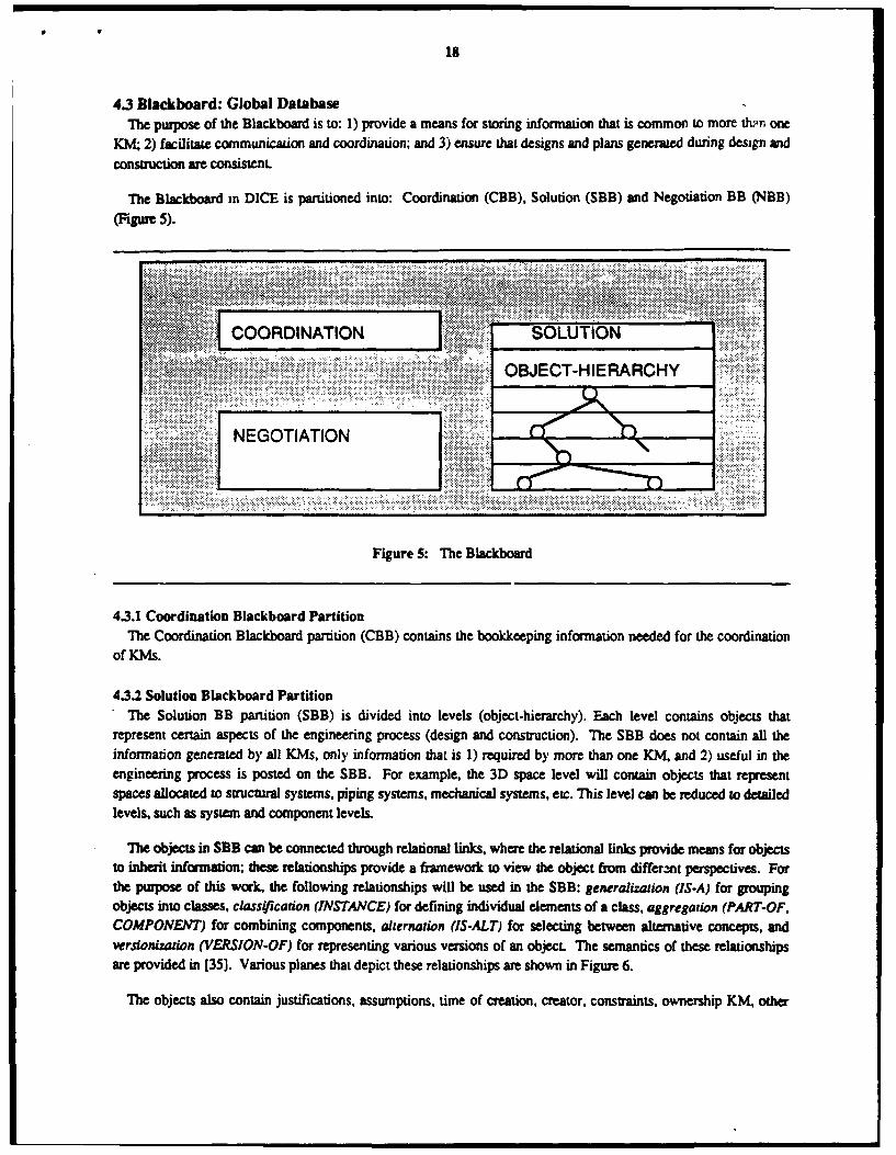
The Blackboard in DICE is partitioned into: Coordination (CBB). Solution (SBB) and Negotiation BB (NBB)(Figure 5).
.................
ICORDINATION SOLUTION
OBJECT-HIERARCHY
Figure 5: The Blackboard
4.3.1 Coordination Blackboard PartitionThe Coordination Blackboard partition (CBB) contains the bookkeeping information needed for the coordination
of KMs.
4.3.2 Solution Blackboard Partition*The Solution BB partition (SBB) is divided into levels (object-hierarchy). Each level contains objects that
represent certain aspects of the engineering process (design and construction). The SBB does not contain all theinformation generated by all KMs, only information that is I) required by more than one KM. and 2) useful in theengineering process is posted on the SBB. For example, the 3D space level will contain objects that representspaces allocated to structural systems, piping systems, mechanical systems, crc. This level can be reduced to detailedlevels, such as system and component levels.
The objects in SBE can be connected through relational links, where the relational links provide means for objectsto inherit information; these relationships provide a framework to view the object from different perspectives. F=orthe purpose of this work, the following relationships will be used in the SBB: generali-,tion (IS-A) for groupingobjects into classes, classificauion (INSTANCE) for defining individual elements of a class, aggregation (PART-OF,COMPONENT) for combining components, alternation (IS-ALT) for selecting between alternative concepts, andverswrdzauwon (VERSION-OF) for representing various versions of an object. The semantics of these relationshipsare provided in [35]. Various planes that depict these relationships are shown in Figure 6.
The objects also contain justifications, assumptions, time of creation, creator, constraints, ownership KM, other

19
CD
C3u
0,0
C3CL)
00
0 10-004-
0.
0 , 0
:0 0
Figure 6: Different Planes in the SBB

20
concerned KMs, etc. The justification information will provide a designer's rationale and intent for the creation of
the object. Assumptions made during design and construction are also stored with the object. For example, thearchitect, while placing the structural elements, may assume certain spatial characteristics for the HVAC systems.
He may record this assumption and the rationale for such an assumption in the objects denoting the appropriate
structural elements and the HVAC system. In DICE, status facets are associated with data attributes (slots). The
status facet, for example, can take the following values: unknown, assumed and calculated. Additional slots will be
needed for the source of data and its change, uses of data, assumptions made, etc..
Associated with these objects are methods which provide a means for 1) performing some procedural
calculations; 2) propagating implications of performing some actions, for example if the status (assumed or actual)or the value for a particular object changes then these changes can be broadcast to all concerned KMs; 3) helping toperform the coordination process. For exampie methods can be used as demons to perform the following
construction related tasks:1. Estimating, whict& involves continuous cost forecasting capabilities, from early estimates to detailed
costs considering the equipment that will be available. This estimating will start with material andquantity modeling based on building standards for tenant work, and would first be updated withcharacteristics of the tenant. As layout work proceeds, material and quantity estimates would beupdated.
2. Scheduling, which is similar in structure to Estimating, and uses much of the quantity data developedfrom the estimate forecast, passed to it with messages.
3. Constructability, where constant critics look for incompatible materials, space use, construction spaceneeds, equipment requirements, etc.
Knowledge for all of these inputs will come from working with expert on all phases of the project, owner, designerand constructor. Further details of the use of methods in the communication process are provided in Section 4.2.
A typical object that resides in the SBB is structured as follows:
SBB-Object
status:CREIt.LD-BY :orosTZb-3!T :
JUSTIFICATIONi:PART-OF:
IS-ALT:
VUSION-OF:VZR.SION-NO:
OWNWD-sY:CONCPJ-I=LS:COMSTLS :
range: (IS-A COXS~TR&N-OB..C2')------ (and so on)
MTiRODS-m
433 Neogotiation Blackboard PartitionThe Negotiation BB (NBB) could be viewed as consisting of two parts. The frst part contains various interaction
constraints that are imposed on the designed object. These constraints am developed during the definition of various

21
levels in SBB7 . The second pan consists of a trace of the negotiation process
An object describing an interaction constraints is:
Constraint-ObjectCONSTh INs:
range: (IS-A SRR-OBJ-CT)fITZRACTZON:
status:range: (S-A ZINTKRACTION-CONSTRAINT)
O¢ms: (as nedad)ICTRNODS:
The status facet can take values like satisfied, suspended, violated, etc. A taxonomy of these constraints can bedefined by the user. Adequate facilities will be provided for the user to incorporate these constraints.
4.4 Knowledge ModulesThe Knowledge-base (KB) consists of a number of Knowledge Modules (KMs). Each of these KMs are further
decomposed into small units called Knowledge Sources (KSs). The architecture of most KMs is similar to theoverall architecture of DICE, i.e., knowledge is distributed among several objects (or KSs) and communicatethrough message passing. KSs can also be decomposed into smaller units, if desired. Thus the KB reflects thehierarchical design process.
Some KMs may incorporate both textbook and heuristic (surface) knowledge, while other KMs may includefairlydeep knowledge. Surface knowledge consists mainly of production rules encoding empirical associations based onexperience. This type of knowledge is useful for setting interface coi|straints between disciplines and between levelsoi design interaction. In a system with deep knowledge, both causal knowledge and analytical models would beincorporated. A fully deep system may be difficult to realize with the current state of the art of KBES. However, itis possible to encode analytical models. In this study, the term fairly deep knowledge will be used to denoteanalytical models.
The KMs, although distributed, can be classified into the following categories: the Strategy, Specialist, andQuantitative KMs. These KMs are briefly described below.
" Strategy KMs analyze the current solution state to determine the course of next action. A scenariousing the Strategic KM is described in Section 6.2. Since this level may used to control various tasks,such as the activation of Specialist KMs during the coordination process, it comprises the task controlknowledge.
" Specialist kMs contribute to various stages of design and construction (or manufacturing). MostKMs at this level are K3ES that have a local Blackboard which may be divided into various levels ofabstraction, and several KSs that interact with the local BE. The possible KMs that could be used inDICE for the domain of interior finishes are:
1. Architectural Designer, for layout and finishes, including flooring and ceiling systems, etr.
2. HVAC, for heat load calculations, duct layout, diffusers, etc.
7Constraimts m ngineering design mn be of two types: onstraints local to the object (designed) and ineraction (interface) construrns thatseveral object& should satisfy sinulanecusly. An example of a local constrmint is Beam.beadng-uztes$ should be less thenO.66Betam.material.yitld.strtus, while the exunple of an interaction constraint is Paper greaser uhao 2 inches camwo go through meet beam orco011591.

22
3./gating, for layout, lighting levels, heat generation, etc.
4. Plumbing, for layout, etc.
5. Construction Planning, for schedules, costs, constructability checking, etc.
6. Structural, only for detailing attachments.Individual KMs will, most probably, be residing on different machines and will make extensive use ofnetworking protocols for communicating with the Blackboard.
" Critic KMs contain the knowledge and mechanisms to check the consistency of the designs.Constraint Handling KM is an example of a Critic KM.
" Quantitative KMs contain the analytical knowledge and reference information required for analysisand design. These KMs are typically comprised of algorithimic programs and databases. QuantitativeKMs comprise the algorithmic knowledge of the domain. The Specialist KMs mostly communicate withthe Quantitative KMs through a Blackboard that is local to the Specialist KM.
The user forms an integral part of these KMs. An important issue in the development of KMs is the aian-machineintwrface and how the information generated by the user is transmitted to other KSs. We assume that the userinteracts with the computer through a high resolution bit mapped display (or appropriate system). Hence, there is aneed to provide the appropriate semantic translations from the information provided by user to the form required byother KMs or KSs. In DICE this is achieved by the interface definition module. Further changes made by the userwill be recorded in the local and global Blackboards (if needed) and appropriate actions triggered. Hence, the user
can be viewed as a KS taking pan in the solution process.
The Kids (mostly Specialist and Strategy) can post and retrieve information from the global Blackboard.
However, an object (and associated attributes) in the Blackboard can have varied connotations (most semantic) indifferent KMs. Hence, there is a need to define the semantic mappings (translations) between the objects in the KMs
to the objects in the Blackboard. As an example, consider the object Beam. In the architectural KM. the beam may
be defied as follows [17]:
BeamLKFT-ZND-COLUMOW-LZNX:LENGTH:WZDTH:
MATZRUL:TYPE:DE PTH:
VIEW
While the same object may be defined in the HVAC KM as:
BeamL-In:R-ZtID:
D:
bU TflTA.L:
R-EZD-NOMIET:
METHODS : possible-cut-outs

23
In the Blackboard, the same object may be defined as:
BeamLECFT-END:IGRT-END:
DEPTH:TYPE:NXTEZAL:CUTOUTS:
locittion:size:
LUT-:D-MObW:RZOT-U)-NO M:
In DICE the methodology used in [17] is being adapted for developing the necessary semantic translations.
4.5 The Negotiation ActivityThe negotiation process takes place once a conflict is detected by the Truth Maintenance System. Negotiation is
achieved through the help of the Strategic KM.
Conflicts can occur either due to interface constraint violation or due to contradictory modifications of a singleobject. For example, a HVAC KM can decide to place pipes at the same location that the architect decided to place abeam. These conflicts can only be detected once the two designs have been posted and sufficient constraintpropagation and/or modeling has been performed. Another type of constraint violation occurs when a KM changesto a partial solution posted by another KM. The two participants may or may not have similar roles in the system.For example, two architects may disagree on the location of the walkway, or the HVAC KM might want to changethe depth of a beam posted by the structural engineer in order to put some pipes through it.
Once a conflict has been identified, a two fold mechanism helps the conflicting KMs in negotiating towards amutually agreed solution. Constraint relaxation is first attempted and is followed by goal negotiation in case offailure.
The first attempt to negotiate involves traditional constraint relaxation techniques and implements compromisebargaining. Assuming that the conflict is due to constraint violations of certain design parameters, the system can actas a third party and offer compromise values to each party until an agreement is reached. In order to allow thisscheme to function properly, each value posted on the Blackboard has to be accompanied by a constraint. Eachconstraint must specify the range of possible values. These constraints can be either soft or hard constraints.
The soft constraints can be negotiated upon and are not imperative. For example, an architect can decide that theaesthetic proportions of a particular beam imposes a certain width to depth ratio, while the structural engineer findsanother ratio guided by strength requirements.
The hard constraints always have to be satisfied. These are usually bounds imposed by code regulations orphysically existing constraints such as a neighboring building, etc. In this case, no relaxation is possible and another
negotiation mechanism has to be triggered. In the case of hard constraints, the range of possible values isautomatically set to a uniqu, value. If the system detects a conflict involving soft constraints which have a non-empty range intersection, it can directly modify these values and notify the KM of the change. If the ranges do not

24
show compatibility, the Strategic KM has to contact the conflicting KMs and initiate constraint relaxation.-In somecases, it is hoped that the ranges themselves have soft constraints and that a compromise can be found.
The second set of techniques involves the redefinition of design goals. The KMs are asked to negotiate on a more
abstract plane. It is considered that the set of conflicting constraints are the concrete expression of an abstract
hierarchy of goals. At the root of this hierarchy is the goal of designing and constructing the artifact for which the
design team has been set up. Each participant develops his own hierarchy of personal goals (see Figure 7 and Figure
8). By helping the KMs frd an agreement goal and developing a common set of more detailed goals, the system
achieves integrative agreement.
The example of the Hyatt Regency walkway connection design will serve as an illustration of the multiple levels
at which this goal negotiation can take place.
At the lowest level, the conflict is in the goals assigned by each participant to the connection and the rod(s). Thedesigner wants the connection to transfer the load of only one walkway, and wants the rod to transfer the load of thetwo walkways to the roof. The fabricator wants each rod to transfer the load of only one walkway, and wants the
connection to bear twice the load. Goal negotiation at this level can lead to a solution where two rods are connectedat some level below the box-beam (see Figure 9). Then, each rod transfers the load of only one walkway and so
does the connection.
At the next level, the system suggests that the connection need not be designed at all. That means that a different
solution can be sought, avoiding the connection of the two parts of the rod and the box-beam. Such a solution couldconsist of hanging each walkway from its own rod directly to the roof as in Figure 10. The aesthetic of this solutionmight not please the architect, but this is another conflict story!
The next level of abstract negotiation would consist of avoiding the design of walkways. This could be done by• )roviding fast convenient elevator service or preventing direct level to level access across the lobby, etc. Evenfurther, the system could suggest to get rid of the lobby and design the whole building differently. By rearranging
the layout, a new solution might be found which doesn't require a lobby. Finally, the participants might come to theconclusion that they have no common goal and that they do not wish to design and construct the building. Some
negotiations are bound to end that way.
5 Current StatusDuring the intial stages our major focus has been the development of: 1) utilities for defining the SBB object
hierarchy, 2) transactions for posting, modifying and deleting information from the Blackboard, 3) a simulationprogram to demonstrate the utility of DICE, and 4) a prototype which involves the automatic generation ofconstruction schedules from an architectural drawing. DICE is being implemented in a hybrid programmingenvironment called PARMENIDES/FRULEKIT; PARMENIDES/FRULEKIT supports programming in frames and
rules and was developed in LISP at Carnegie-Mellon University by Carbonell and Shell.
These topics are briefly described below.
5.1 Graphic Definition of ObjectsThe user can interactively define class objectsO in the Blackboard and the KMs. Classee can either be created in
$A class denotes the grouping of objects (instance or class) whic& have similar characteristic&, while A instance is a panicular individualwhich belongs to a class.

25
Construction ofthe Building
Fiurh e RDeogof Goal HWearch ys

26
Construction ofthe Building
I Construction ofthe Lobby
SConstruction of Construction of
the Roof the Walkways
STransfer of Load of Transfer of Load ofWalkway 2 to Walkway 2 & 4 to Rod
Roof Through 1 Rod Through Connection
Transfer of Load ofWalkway 4 to
Roof Through 1 Rod
Figure 8: The Fabricator's Goal Hierarchy

27
box-beam
---rod #1
i coupler
4 ...- .rod #2
Figure 9: The Connected Rods Solution
LISP or through a menu interface provided to the user. Each class has a name, several slots which describe variousattributes, and associated with each slot are facets which provide further information about the slot, the facets alsocontain methods.
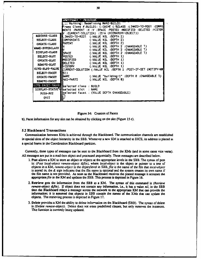
A class object is created by clicking on CREATE-CLASS in a menu on the screen. After creating a class object, theuser can display the class using the DISPLAY-CLASS option, as shown in Figure 11. In Figure 12, the class BuildI ismade a subclass of the Hierarchy-object class, which becomes Buildi's superclass. When this fink is made, allslots in the Hierarchy-object class are inherited by Buildl. In addition, the user can create new slots or delete slots.For example, in Figure 13 the user created two Slots, namely NAME and HAS-PARTS. Slots can be faceted ornon-faceted. The creation of facets is shown in Figure 14.
Instances of a class can either be defined interactively through a menu or by LISP functions. For example thefunction (create-instance 'Build] 'Hyatt-regency) would create an instance, Hyatt-regency, of Build 1.
In addition to defining classes and instances, the user can also display the class hierarchy, in the form of a tree.Nodes in the tree depict classes and instances. Each node is displayed in a box with the name of the class orinstance. If the name does not fit in the box then it is abbreviated. The user can drag the mouse pointer over the tree

* 28
* . ... '. .... ...* ... .
Figure 10: The Split Connections Solution
RESTORE-CLASSSELECT-CLASSCREATE-CLASS
NAME-SUPECLASS
SELECT-SLOTCREATE-SLOTREMOVYE-SLOT
GIVE-SLOT-VALUE *::SELECT-FACETCREATE-FACET
'.OV FACE : (menu-create-class)GIYE-FACET-VAUE efnn class BUILDIDISPLAY-STATVS ; Warning: Redefining MAKE-BUILD1
PUSH-PUT rame Class 1:500L1: (:CACHE (:*kCLASS) :13-A NIL)QUIT
Figure 11: Displaying a Class
to an appropriate node. This will display the full name of the node (Figure 15 a). If the user wants more detail about

29
RESTOR.E-CLASSSELECT-CLASS etinng class BUILD1CREATrE-CL.ASS Wann:Redefining MAKE-BUILD1
* rame Class I:BUILDI: (:CACHE (:%CLASS :LINKED-7O-ROOI :COM.DISPLAY-CASS ONEN7S :PARENT :X :Y :SPACE :POSTED :MODIFIED :DELETED :HISELECTSLOT TORY :CURREN7-SOLITION) :IS-A (HIERARCHY-OBJECT))SELEC-SLOT INKED-10-ROOT (:VALUE NIL :DEPTH 2)
CREATE-SLOT i OMPONENTS (:VALUE NIL :DEPTH 2)*~ RENT (:VALUIE NIL :DEPTH 2)
R(VSLT x (:VALUE NIL :DEPTH 2 :CHANGEABLE 7)GIE-LT ALE(:VALUE NIL :DEPTH 2 :CHANGEABLE 7)
SELEXCT-FACET ':*SPACE (:VALUIE NIL :DEPTH 2 :CHIANGEABLE 1)CRE.ATE-FACET POSTED (:VALUE NIL :DEPTH 1)
FAET ODIFIED (:VALUE NIL :DEPTH 1)REKOVE EETD(:ALENI :ETh1GIVE-AEVAU HIS70RY (:VALUE NIL :DEPTH 1)DISPLAY-STATUS CURRENI SOLUTION (:VALUE NIL :DEPTH I :POST-IF-SET (NOTIFY-
PUSH- PUTi KMS))
QUIT
Figure 12: Linking a Class to its Supwiclass
E (:VALUE "building-I" :DEPTH 8 :CHANGEABLE 1)S-PARTS (:VALUE NIL :DEPTH 8)
stifling class BUILD1RESTORE-CLASS ,;; Warning: Redefining MAKE-BUILD1SELECT-CLASS -rants Class 1:BUILD1: (:CACHE (:%.CLASS :LINKED-TO-ROOT :COMPO
CREATE-CUSS NENTS :PARENT :X :Y :SPACE :POSTED :MODIFIED :DELETED :HIS7ORNAKESUPRCLAS :CURRENI-SDLUTION) : IS-A (HIERARCMY-OBJECT))
'-~SP~LS ~.INKED-70-ROOT (:VALUE NIL :DEPTH 2)DISPLA!-CLASS 1ZOMPONENTS (:VALUE NIL :DEPTH 2)
SELECT-SLOT PARENT (:VALUE NIL :DEPTH 2). -V I x(:VALUE NIL :DEPTH 2 :CHANGEABLE 1)PM40E-SLT y(:VALUJE NIL :DEPTH 2 :CHANGEABLE T)
RIOESPACE (:VALUE NIL :DEPTH 2 :CHIANGEABLE T)CIV -SLO)T-VALUE 'OSTED (:VALUE NIL :DEPTH 1)SELECT-FACET ODIFIED (:VALUE NIL :DEPTH 1)
CREATE-FACET ELETED (:VALUE NIL :DEPTH 1)
REMOVE-FACET H ISTORY (:VALUE NIL :DEPTH 1)
CURRENT-SOLUTION (:VALUE NIL :DEPTH I :POST-IF-SET (NOTIFY-Q4GIVE-TACET-YAWUEDISPLAY-STATUS NME (:VALUE "building-i" :DEPTH 8 :CHANGEABLE T)
PUI-PUT RAS-PARTS (:VALUE NIL :DEPTH 8)
QUIT
Figure 13: Creation of Slots
the node, he can click on the node and hc will be shown the Slots of the object corresponding to the node (Figure 15
;; Warning: Redefining MAKE-BUILD1rame Class I:BUILDI: (:CACHE (:%CLASS :LINKED-7D-RO07 :COMPDENTS :PARENT :X :Y :SPACE :POSTED :MODIFIED :DELETED :HISTORf :CURRENT-SOLUTION) :IS-A (HIERARCHY-OBJECT))
RESTORE-CLASS ,INKED-TO-ROO1 (:VALUE NIL :DEPTH 2)SELECT-CLASS COMPONENTS (:VALUE NIL :DEPTH 2)CREATE-CLASS PARENT (:VALUE NIL :DEPTH 2)
K (:VALUE NIL :DEPTH 2 :CHANGEABLE 7)KA~~UP CL S (:VALUE NIL :DEPTH 2 :CHANGEABLE 1)DISPL.Y-CLASS 5PACE (:VALUE NIL :DEPTH 2 :CHANGEABLE T)SELECT-SLOT DOSTED (:VALUE NIL :DEPTH 1)CREATE-SLOT MODIFIED (:VALUE NIL :DEPTH 1)REMOVE-SLOT DELETED ( :VALUE NIL :DEPTH 1)-ISTORY (:VALUE NIL :DEPTH 1)
GIVE-SLOT-VALUE CURRENT-SOLUTION (:VALUE NIL :DEPTH 1 :POST-IF-SET (NOTIFY-IKSELECT-FACET S))CREATE-FACET NAME (:VALUE "building-l" :DEPTH B :CHANGEABLE T)
R-XOVE-FACET LIS-PARTS (:VALUE NIL :DEPTH 0)
1 , :1: selected class BUILDDISPLA¥-STATUS' selected slct NAME
SH-PUT selected facet (VALUE DEPTH CHANGEABLE)
QUIT
Figure 14: Creation of Facets
b). Facet information for any slot can be obtained by clicking on the slot (Figure 15 c).
5.2 Blackboard TransactionsCommunication between KMs is achieved through the Blackboard. The communication channels are established
in special slots of the object hierarchy in the SBB. Whenever a new KM is attached to DICE, its address is placed ina special frame in the Coordination Blackboard partition.
Currently, three types of messages can be sent to the Blackboard from the KMs (and in some cases vice versa).All messages are put in a mail-box object and processed sequentially. These messages are described below.
1. Post allows a KM to store an object or objects at the appropriate levels in the SBB. The syntax of postis: (Post local-object remote-object &file), where local-object is the object or pointer to a tree ofobjects in a KM. remote-object is the object/level in SBB,file is the name of the file that local-objectis stored in; the & sign indicates that the file name is optional and the system creates its own name ifthe file name is not provided. As soon as the Blackboard receives the posted message it accesses theappropriateffle in the KM and updates the SBB. This process is depicted in Figure 16.
2. Retrieve gets the information from the SBB to a KM. The syntax of this command is (Retrieveremote-object &fAle). If object does not contain any information, Le., it has a value ail, in the SBBthen the Blackboard relays a message across the network to the appropriate KM that can provide theinformation; it is assumed that objects in SBB contain the names of the KMs that can update theobjects. The retrieving process is depicted in Figure 17.
3. Delete provides a KM the ability to delete information on the Blackboard (SBB). The syntax of deleteis (Delete remote-object). Delete does not erase predefined classes, but only removes the instances.This function is currently being updated.

131
0~2 21r
3 W
94 C?*C'
-u 0 0
0 0 0 0
0P -03 U
Fiur IS ipa fte betHeac

32
knowledge module blackboard
-1 ra me-74
mailbox \ r -
posingfrae-ionobj-l
rarame-
mailboxalboframe-1
retrieiin frame-In bj
Figure 1: Retrieing Informnaton to~ the Blackboard

33
5.3 A SimulationA simulation of the Hyatt Regency design process was developed on two SUN computers to demonstrate some of
the capabilities of DICE. A Blackboard, a Critic KM. a Constraint Manager KM, and a Strategic KM exist on thefirst machine (Figure 18). while a Connection Designer KM and a Structural Fabricator KM reside on the secondmachine (Figure 19).
The design-fabrication sequence is described below and shown in Figures 19 through 24.1. Connection designer KM posts the connection design (denoted by I -rod-connection) of the fourth floor
walkway on the Blackboard (Figure 19 a).
2. Blackboard receives the design (Figure 20 a and b).
3. The connection object has a method that indicates that the connection design should be checked by theCritic KM. Hence. the Blackboard sends the connection design to the Critic KM (Figure 20 c and d).
4. The Critic KM replies that the connection design is acceptable9 (Figure 20 e).
5. The Structural Fabricator KM is sent a message that a connection design has been completed andneeds fabrication (Figure 21 a). The Fabricator retrieves the connection design, makes modificationsand sends it back to the Blackboard (Figure 22 a, Figure 23 a and b).
6. Blackboard notifies the Strategic KM to check for possible conflicts (Figure 23 c).
7. Strategic KM retrieves the two connection (rod) designs (Figure 23 d) and sends it to the ConstraintManager KM to check for violation of interface constraints (Figure 23 e).
8. Constraint Manager KM notifies the Strategic KM that the designs are incompatible (Figure 23 f).
9. Strategic KM notifies this to both the Connection Designer and the Structural Fabricator (Figure 22 band c, Figure 24 a and b).
The above simulation program was completed in December 1987. In the next section, a project that wasundertaken during January 1988 to September 1988 to demonstrate the interface definition modules is described1 ° .Implementation details can be found in [15].
91n the actual design the original connection design itself was faulty. but we assume heme that it is an sceptable design.
2°The 'RB was not uilized in the above simulation.

34
........ ......
3
3
~ 3
- S3
3
m
K
U ~;; ~.w
-m
Figure iS: Set up for Siniulauon of ihc Hyau Rcgenc) Design Problem

35i
F f 7
... .. .. ... ... . .... .. ... .
- - - ----- -... ....
----- ---...- .........
.. ... ... . . . . . . . . . . . .. . . . . . . . . . . .
.. ... . .. .... ..
.. ... . .. ..... .... .. ..
.___ ...... -........ ....
F.gure ..9. ...... up .o ...... .f .... Hy. Regnc.Deig.Prole ..C.

C I-
V to
ato
........ .. .. .. .
cr :r c c cr .... ... -----ml- ft E
- IIx
t-.Lw?. ILc
- s-'~'s'~'-~-_j
UI
&
Ko IL
Figure 20: Simuilation

c U
FU
C
L IM
W, 0
IVV
M, ...
.. . ...
0 ... . . . .
..... ....
.' . . .. .... . .... .
. .. . ..
. . .
SFigr 21 Siuain(Cniud

7-C
> Cr-6 C
Z.
Im CC 6. .~ E
CC
LCA 6.
LP U a.
45 U 4mI x U
, a aV
orc r c c~ c~£ £ L-~~~ ~ c ~Ua g
.... .. .~ . 5 ..... - .. ...... .. ... . .... .3 W r~ .L ........... a.
... . ...... r6'- - - - --- --
.... .. . ........ ............ .... ......... . ... so. ... .. . . .. .. .. .
. .. .0 .0 .V .~ .0 . . .E .- .
......... .... .. .. . . . . ..g .0 .0 .0 . .* .' .. .6.~ ..O .. ..- ....
.. . ... ........ ....
-- - - --- --.
m. ...... ...-...- ________________ _____
Figure 22: SimulaLion (Confinucd)

93
. .. . . .. .
-v z - U -nC
61 -
400
.0
w
w U- -at E
-, E. Us X .' -a-
1A 4,0. -c* h W
0L 0 ~ .0 am v- er 0a - a - a X.0
.c,- OL! ~
U 0
91LI N W
55 -
Figure 23: Simulaion (Coninued)

40
... .. . L
0.;2.
a Von A) #- "wR&
6U
p FFF
igi
(-Job
Fgr 24 Siuato (Comif
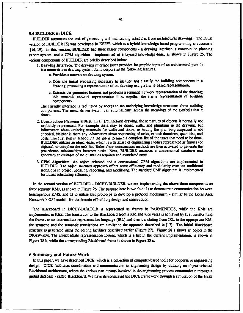
41
5.4 BUILDER in DICEBUILDER automates the task of generating and maintaining schedules from architectural drawings. The initial
version of BUILDER [5] was developed in KEE", which is a hybrid knowledge-based programming environment(14, 19]. In this version, BUILDER had three major components - a drawing interface, a construction planning
expert system, and a CPM algorithm - implemented as a layered knowledge-base, as shown in Figure 25. The
various components of BUILDER are briefly described below.1. Drawing Interface. The drawing interface layer provides for graphic input of an architectural plan. It
is a menu-driven drafting system that incorporates the following features.a. Provides a convenient drawing system.
b. Does the initial processing necessary to identify and classify the building components in adrawing, producing a representation of tL. drawing using a frame-based representation.
c. Extracts the geometric features and produces a semantic network representation of the drawing;this semantic network repro.sentation links together the frame representation of buildingcomponents.
The friendly interface is facilitated by access to the underlying knowledge structures about buildingcomponents. The menu driven system can automatically access the meanings of the symbols that itdraws.
2. Construction Planning KBES. In an architectural drawing, the semantics of objects is normally notexplicitly represented. For example there may be doors, walls, and plumbing in the drawing, butinformation about ordering materials for walls and doors, or having the plumbing inspected is notencoded. Neither is there any information about sequencing of tasks, or task durations, quantities, andcosts. The first step in scheduling the job is to make a complete list of the tasks that need to be done.BUILDER utilizes an object-base, which is a database of engineering entities represented as frames (orobjects), to complete the task list. Rules about construction methods are then activated to generate theprecedence relationships between tasks. Next, BUILDER accesses a conventional database andgenerates an estimate of the quantities required and associated costs.
3. CPM Algorithm. An object oriented and a conventional CPM algorithms are implemented inBUILDER. The object oriented approach offers some efficiency and modularity over the traditionaltechnique in project updating, reporting, and modifying. The standard CMP algorithm is implementedfor initial scheduling efficiency.
In the second version of BUILDER - DICEY-BUILDER, we are implementing the above three components asthree separate KMs, as shown in Figure 26. The purpose here is two fold: 1) to demonstrate communication betweenheterogenous KMS, and 2) to utilize this prototype to develop a protocol mechanism - similar to the Local AreaNetework's OSI model - for the domain of building design and construction.
The Blackboard in DICEY-BUILDER is represented as frames in PARMENIDES, while the KMs areimplemented in KEE. The translation to the Blackboard from a KM and vice versa is achieved by first transformingthe frames to an intermediate representation language ([ML) and then translating from IRL to the appropriate KM;the syntactic and the semantic translations are similar to the approach described in [17]. The initial Blackboardstructure is generated using the editing facilities described earlier (Figure 27). Figure 28 a shows an object in theDRAW-KM. The intermediate representation format, which is a list in the current implementation, is shown inFigure 28 b, while the corresponding Blackboard frame is shown in Figure 28 C.
6 Summary and Future WorkIn this paper, we have described DICE, which is a collection of computer-based tools for cooperative engineering
design. DICE facilitates coordination and communication in engineering design by utilizing an object orientedBlackboard architecture, where the various participants involved in the engineering process communicate through aglobal database - called Blackboard. We have demonstrated the DICE framework through a simulation of the Hyan

42
Context Layered Knowledge Base
DRAWING
DrawingInterface
SEMANTICNETWORK
(D
ConstructionPlanningExpert SystemPRQJECT
0NETWORK
........... ...CPM
SCHEDULE Schedulingand EstimatingESTIMATE
Figure 25: Schematic View of BUILDER
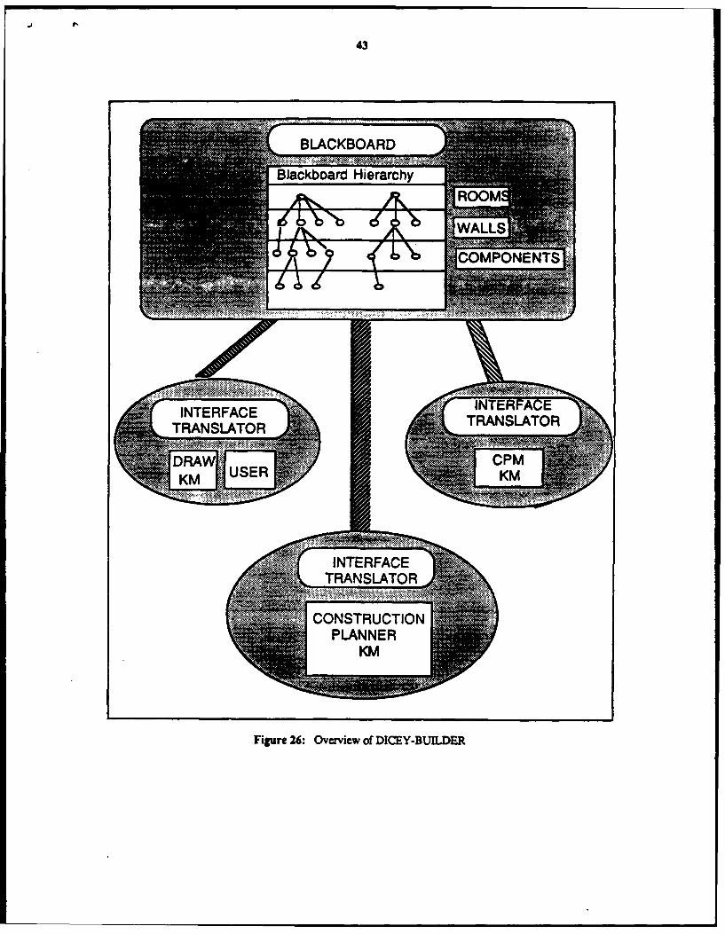
43
BLACKBOARD...... .....Blackboard Hierarchy
46 -'bN dilbI Al.,86 PONENTS;'..':
6...... ......
f 6 1-' --wl- I "W, -I.R. ......
L 71NTERFACE INTERFACE
TRANSLATOR TRANSI. ATOR
DRA CPMUSER KhAKM
INTERFA ETRANSLA R
CONSTRUCTIONPLANNER
KM
Figure 26: Overview of DICEY-BUILDER

44
KE tfra 27 tin IRL atranslation PARMENIDESfo rart omat format d
a b C /envelope
BLACKBOAR D machine to machine ('BLACKBOARD
l m message f il transfer message p
read •d
message
format J , object
Fig -ire 27: Posting From KM to Blackboard: Translation Process
Regency Disaster and an implementation of a construction planning KBES. Our current efforts are being focused inthe following areas: 1) a theory of constraint negotiation for resolving conflicts between various designers, 2) alayered communication protocol that will facilitate an effective communication process between participants in
different engineering disciplines, 3) an user interface in the X window system, 4) effective secondary storagemanagement facilities, and 5) demonstrate DICE in an industrial setting.

45
Unit: WALL144 in knowledge base DRAWCreated by jonathan on 5-27-88 13:18:25Modified by nick on 5-27-88 13:20:34
lMntv~ WALLS
Own slot: BOUND from WALLSInheriance: OVERRIDE.VALUES
Vaks, UNKNOWNA~
Own slot: CONNECTED-TO from WALL144Inheritance: OVERRIDE. VALUES
Vakjss((WALL185 ((311.0 95.0) (301.0 95.0)))) (walll44
Own~ slut: CONNEiCTION-MANAGER fiorn WALL 144 (c1*iss walls)Inheritanoe: METHOD (contains l)
Vle:IDRAW.WALLS:CONNECTION-MANAGER'metdhod (picture-representationVakiss:walxectaragle145)
Own slot: CONSTRAINED-BY from WALL144 (constrained-by wall1185)Inheritance: OVERRIDE.VALUES Mbound ril)
Vakac WALL 185 (connecied-to((wausS
Own slot: CONTAINS from SYMBOLS (p1.095)lnhertance: OVERRIDE.VALUES PJ9X)))
Vakws UNKNOW#N
Own slot: MOTION-CONSTRAINTS from WALLS bInheritance: METHODVWuiusus: METHODVakas: IDRAW>WALLS:MOTlON-CONSTRAINTSlmfethod)
Own slot: PICTURE-REPRESENTATION from WALLI 44aInheriance: OVERRIDE.VALUESa
Values: WALLRECTANGLE145
Frame WALLi 44:(,CACHE 0)
CONTAINS NILPICTURE-REPRESENTATION (:VALUE WALLRECTANGLE1 45)CONSTRAINED-BY (:VALUE WALL185)BOUND (:VALUE NIL)CONNECTED-TO (:VALUE ((WALLI 85 ((311.0 95.0) (301.0 95.0))))))) C
Figure 28: Representaive Objects

r
46
7 Bibliography[1] Amarel, S.. "Basic Themes and Problems in Current A] Research," Proceedings of the Fourth Annual AIM
Workshop, Ceilsielske, V. B., Ed., Rutgers University, pp. 28-46, June 1978.
[2] Barton, P. K., Building Services Integration, E. F. N. Spon, 733 Third Ave., NY 10017, 1983.
[3] Cellary, W., Gelenbe, E., and Morzy, T., Concurrency Control in Distributed Database Systems. ElsevierScience Publishers B.V., 52 Vanderbilt Avenue, NY 10017, 1988.
[4] Chang, S-K., Khikawa, T., and Ligomenides, P. A., Eds., Visual Languages, Plenum Press, New York, 1986.
[5] Cherneff, J., Automatic Generation of Construction Schedules from Arcitectural Drawings, unpublishedMaster's Thesis, Dept. of Civil Engineering, M.I.T., Cambridge, MA 02139, 1988.
[6] Conry, S., Meyer, R., Lesser, V., "Multistage Negotiation in Distributed Planning," Readings in DistributedArtificial intelligence, pp. pg 367-384, 1988.
[7] CouWouris, G. and Dollirnorc, J.. Distrihuted Systems: Conceps and Design, Addison Wesley, 1998
[8] Davis, R., Smith, R., "Negotiation as a Metaphor for Distributed Problem Solving," Artificial Intelligence,Vol. 20, pp. pg 63-109, 1983.
[9] de Kleer, J., "Choices Without Backtracking," Proceedings of the 4th NCAJ, Texas, AAAI, August 1984.
[10] Doyle, J., "A Truth Maintenance System," Artificial Intelligence, Vol. 12, pp. 231-272, 1979.
[11] Eastman, C. M., "Database Facilities for Engineering Design," Proceedings of the IEEE, Vol. 69, No. 10,pp. 1249-1263, October 1981.
[12] Erman, L. D., Hayes-Roth, F., Lesser, V. R., and Reddy, D. R., "The Hearsay-il Speach UnderstandingSystem: Integrating Knowledge to Resolve Uncertainty," Computing Surveys, Vol. 12, No. 2, pp. 213-253,1980.
[13] Fenves, S., Flemming, U., Hendrickson, C., Maher, M., Schmitt, G., "An Integrated Software Environmentfor Building Design and Construction," Computing in Civil Engineering: Microcomputers toSupercomputers, 1988.
[14] Fikes, R. and Kehler, T., "The Role of Frame-based Representation in Reasoning," Communications of theACM, pp. 904-920, September 1988.
[15] Groleau, N., A Blackboard Architecture for Communication And Coordination in Design, unpublishedMaster's Thesis, Dept. of Civil Engineering, M.LT., Cambridge, MA 02139, 1989.
[16] Hayes-Roth, B., "A Blackboard Architecture for Control," Artificial Intelligence, Vol. 26, No. 3,pp. 251-321, 1985, [Also Technical Report No. HPP 83-38, Stanford University.].
[17] Howard, H.C., Integrating Knowledge-Based Systems with Database Management Systems for StructuralEngineering Applications, unpublished Ph.D. Dissertation, Department of Civil Engineering, CarnegieMellon University, Pittsburgh, PA 15213, 1986, [See also Special Issue of CAD, November 1985.].
[18] Katz, R., Information Management for Engineering Design. Springer-Verlag, 1985.
[19] "KEE Software Development Manual," Intellicorp, Palo Alto, 1987.
[20] Klein, M., Lu, L., "Run-Time Conflict Resolution in Cooperative Design," Workshop on A[ in EngineeringDesign, AAAI-88, 1988.
[21] Krasner, H., "CSCW'86 Conference Summary Report," Al Magazine, pp. 87-88, Fall 1987.
[22] Lander, S., Lesser, V., "Negotiation of Conflicts Among design Experts," Workshop on Al in EngineeringDesign. AAAI-88, 1988.
[23] Maier, D., Stein, J., Otis, A., and Purdy, A., "Development of an Object-Oriented DBMS," OOPSLA 86,,pp.. 1986.
[24] Marshall, R. D., et al., Investigation of the Kansas City Hyatt Regency Walkways Collapse, Technical ReportScience Series 143, National Bureau of Standards, Washintong, D. C., May 1982.

47
[25] Nii, P. and Brown, H., "Blackboard Architectures." AAAI Tutorial Notes No. HA2, 1987.
[26] Nii, P., Fiegenbaum E., Anton, J. and Rockmore, A.. "Signal-to-Symbol Transformation: HASP/SlIAP CaseStudy," The A/ Magazine, Vol. 3, No. 2. pp. 23-35, Spnng 1982.
[27] Papsdimitriou, C., The Theory of Database Concurrency Control, Computer Science Press, Inc., 1803Research Boulevard, Rockville, Maryland 20850, 1986.
[28] Pruitt, D.,. Negotiation Behavior, Academic Press, 1981.
[29] Reddy, R., Erkes, J., Wood, R., "An Overview of DICE Architecture," DARPA draft proposal by WestVirginia University, 1988.
[30] Rehak, D.R., Howard. H.C., and Sriram, D., "Architecture of an Integrated Knowledge Based Environmentfor Structural Engineering Applications," in Knowledge Engineering in Computer-Aided Design, Gero, J.,Ed., North Holland, 1985.
[31] Rosenschein, J., Genesereth, M., "Deals Among Rational Agents," Readings in Distributed ArtificialIntelligence, pp. pg 227-234, 1988.
[32) Sathi, A., Cooperation Through Constraint Directed Negotiation: Study of Resource Reallocation Problems,Technical Report, Carnegie-Mellon University, Robotics Institute, 1988.
[33] Sathi, A., Morton, T., and Roth, S., "Callisto: An Intelligent Project Management System," Al Magazine,Vol., pp. 34-52, Winter 1986.
[34] Sriram, D., "DESTINY: A Model for Integrated Smctura] Design," International Journal for Al in
Engineering, October, 1986.
[35] Sriram, D., Knowledge-Based Approaches for Structural Design, CM Publications, UK, 1987.
(36] Sriram, D., Ed., Computer Aided Engineering: The Knowledge Frontier, IESL, Dept. of Civil Engineering,MJ.T., 1989.
[37) Stefik, M. and Bobrow, D., "Object-Oriented Programming: Themes and Variations," The Al Magazine,VoL Winter, pp. 40-b2, 1985.