Embed Size (px)
Citation preview

Signals and Systems
Laplace Transform and Its Applications
Student: Ali Abbasi (ID: 9531503)
Course Instructors: Dr. M Shahraki, Dr. M Mehrjoo
Course Number: 20 14 255
Faculty of Electrical and Computer Engineering,
University of Sistan and Baluchestan, Zahedan, Iran
Note: All trademarks, logos, service marks displayed, and software used to make
this video are the trade mark of their respective company.

2/16
Frequency Range
Note: This slide has been used in assignment 9 to present applications of Fourier analysis.

3/16
Audio Systems with Multiple Speakers
Picture Source: https://www.bhphotovideo.com/explora/amp/audio/tips-and-solutions/what-about-all-those-speaker-specs
Note: This slide has been used in assignment 9 to present applications of Fourier analysis.

Filters Circuits
Picture Source: Santiago, J. (2013). Circuit Analysis for Dummies: John Wiley & Sons. (with modifications)
4/16

Low-pass Filter Analysis
5/16Picture Source: Santiago, J. (2013). Circuit Analysis for Dummies: John Wiley & Sons. (with modifications)
𝑣𝑖𝑛 𝑡 = 𝑣𝑅(𝑡) + 𝑣𝑜𝑢𝑡(𝑡)
𝑣𝑖𝑛 𝑡 = 𝑅𝐶𝑑𝑣𝑜𝑢𝑡(𝑡)
𝑑𝑡+1
𝐶න−∞
𝑡
𝐶𝑑𝑣𝑜𝑢𝑡(𝜏)
𝑑𝑡𝑑𝜏
𝑣𝑖𝑛 𝑡 = 𝑅𝑖(𝑡) +1
𝐶න−∞
𝑡
𝑖(𝜏) 𝑑𝜏
𝑣𝑖𝑛 𝑡 = 𝑅𝐶𝑑𝑣𝑜𝑢𝑡(𝑡)
𝑑𝑡+ 𝑣𝑜𝑢𝑡(𝑡)
𝑣𝑅(𝑡)
𝑣𝑜𝑢𝑡(𝑡)𝑣𝑖𝑛(𝑡)
𝑅
𝐶 𝐴𝑙𝑙 𝑖𝑛𝑖𝑡𝑖𝑎𝑙 𝑐𝑜𝑛𝑑𝑖𝑡𝑖𝑜𝑛𝑠 𝑎𝑟𝑒 𝑧𝑒𝑟𝑜.

Low-pass Filter Analysis (cont.)
6/16
𝑣𝑖𝑛 𝑡 = 𝑅𝐶𝑑𝑣𝑜𝑢𝑡(𝑡)
𝑑𝑡+ 𝑣𝑜𝑢𝑡(𝑡)
𝑣𝑜𝑢𝑡 𝑡 = 𝑣𝑖𝑛(𝑡)(1 − 𝑒−1𝑅𝐶
𝑡)
𝑉𝑖𝑛 𝑠 = 𝑅𝐶𝑠𝑉𝑜𝑢𝑡(𝑠) + 𝑉𝑜𝑢𝑡(𝑠)
𝑉𝑖𝑛 𝑠 = 𝑉𝑜𝑢𝑡(𝑠)(𝑅𝐶𝑠 + 1)
𝑉𝑜𝑢𝑡 𝑠 =1
𝑅𝐶(
1
𝑠 +1𝑅𝐶
)𝑉𝑖𝑛(𝑠)
𝐿𝑎𝑝𝑙𝑎𝑐𝑒
𝐿𝑎𝑝𝑙𝑎𝑐𝑒−1

Devices in S-Domain
7/16
𝑫𝒆𝒗𝒊𝒄𝒆 𝑻𝒊𝒎𝒆 − 𝑫𝒐𝒎𝒂𝒊𝒏
𝑺 − 𝑫𝒐𝒎𝒂𝒊𝒏
𝑽𝒐𝒍𝒕𝒂𝒈𝒆 𝑪𝒖𝒓𝒓𝒆𝒏𝒕𝑰𝒎𝒑𝒆𝒅𝒂𝒏𝒄𝒆(𝒘𝒊𝒕𝒉 𝒛𝒆𝒓𝒐𝒊𝒏𝒊𝒕𝒊𝒂𝒍
𝒄𝒐𝒏𝒅𝒊𝒕𝒊𝒐𝒏)
𝐼𝑉𝑆 𝑣𝑆(𝑡) 𝑉𝑆(𝑠) − −
𝐼𝐶𝑆 𝑖𝑆(𝑡) − 𝐼𝑆(𝑠) −
𝑉𝐶𝑉𝑆 𝑣2 𝑡 = 𝜇𝑣1 𝑡 𝑉2 𝑠 = 𝜇𝑉1 𝑠 − −
𝑉𝐶𝐶𝑆 𝑖2 𝑡 = 𝑔𝑣1 𝑡 − 𝐼2 𝑠 = 𝑔𝑉1 𝑠 −
𝐶𝐶𝑉𝑆 𝑣2 𝑡 = 𝑟𝑖1 𝑡 𝑉2 𝑠 = 𝑟𝐼1 𝑠 − −
𝐶𝐶𝐶𝑆 𝑖2 𝑡 = 𝛽𝑖1 𝑡 − 𝐼2 𝑠 = 𝛽𝐼1 𝑠 −
𝑅𝑒𝑠𝑖𝑠𝑡𝑜𝑟 𝑣𝑅 𝑡 = 𝑅𝑖𝑅(𝑡) 𝑉𝑅 𝑠 = 𝑅𝐼𝑅(𝑠)𝐼𝑅 𝑠 =
1
𝑅𝑉𝑅(𝑠)
𝑍𝑅 𝑠 = 𝑅
𝐶𝑎𝑝𝑎𝑐𝑖𝑡𝑜𝑟𝑣𝐶 𝑡 = න
0
𝑡
𝑖𝐶(𝜏) 𝑑𝜏 𝑉𝐶 𝑠 =1
𝑠𝐶𝐼𝐶 𝑠 +
𝑣𝑐(0)
𝑠
𝐼𝐶 𝑠 = 𝑠𝐶 𝑉𝐶 𝑠 − 𝐶𝑣𝑐(0) 𝑍𝐶 𝑠 =1
𝑠𝐶
𝐼𝑛𝑑𝑢𝑐𝑡𝑜𝑟𝑣𝐿 𝑡 = 𝐿
𝑑𝑖𝐿(𝑡)
𝑑𝑡
𝑉𝐿 𝑠 = 𝑠𝐿𝐼𝐿 𝑠 − 𝐿𝑖𝐿(0)𝐼𝐿 𝑠 =
1
𝑠𝐿𝑉𝐿 𝑠 +
𝑖𝐿(0)
𝑠
𝑍𝐿 𝑠 = 𝑠𝐿

S-Domain Thévenin’s and Norton’s Equivalent for Passive Elements
8/16Picture Source: Santiago, J. (2013). Circuit Analysis for Dummies: John Wiley & Sons. (with modifications)

Band-pass Filter: S-Domain Analysis
9/16Picture Source: Santiago, J. (2013). Circuit Analysis for Dummies: John Wiley & Sons. (with modifications)
𝑉𝑖𝑛(𝑠) 𝑉𝑜𝑢𝑡(𝑠)𝑅1
𝑠𝐶
𝑠𝐿
𝑉𝑜𝑢𝑡 𝑠 =𝑅
𝑠𝐿 +1𝑠𝐶
+ 𝑅𝑉𝑖𝑛 𝑠
𝑇 𝑠 =𝑉𝑜𝑢𝑡(𝑠)
𝑉𝑖𝑛(𝑠)=
𝑅
𝐿
𝑠
𝑠2 +𝑅𝐿
𝑠 +1𝐿𝐶
𝐴𝑙𝑙 𝑖𝑛𝑖𝑡𝑖𝑎𝑙 𝑐𝑜𝑛𝑑𝑖𝑡𝑖𝑜𝑛𝑠 𝑎𝑟𝑒 𝑧𝑒𝑟𝑜.

Band-pass Filter: S-Domain Analysis (cont.)
10/16
1
𝐿𝐶− 𝜔2 = ±
𝑅
𝐿𝜔 → 𝜔2 ±
𝑅
𝐿𝜔 −
1
𝐿𝐶= 0 →
𝜔𝐶1 = −𝑅
2𝐿+
𝑅
2𝐿
2
+1
𝐿𝐶
𝜔𝐶2 = +𝑅
2𝐿+
𝑅
2𝐿
2
+1
𝐿𝐶
1
𝐿𝐶− 𝜔2 = 0 → 𝜔0 =
1
𝐿𝐶
𝐵𝑎𝑛𝑑_𝑤𝑖𝑑𝑡ℎ = 𝜔𝐶2 − 𝜔𝐶1 =𝑅
𝐿𝑎𝑛𝑑 𝑄_𝑓𝑎𝑐𝑡𝑜𝑟 =
𝜔0
𝐵𝑎𝑛𝑑𝑊𝑖𝑑𝑡ℎ=1/ 𝐿𝐶
𝑅/𝐿=1
𝑅
𝐿
𝐶
𝑠 = 𝑗𝜔 → 𝑇 𝑗𝜔 =𝑉𝑜𝑢𝑡(𝑗𝜔)
𝑉𝑖𝑛(𝑗𝜔)=
𝑅
𝐿
𝑗𝜔
𝑗𝜔 2 +𝑅𝐿
𝑠 +1𝐿𝐶
=𝑅
𝐿
𝑗𝜔
1𝐿𝐶
− 𝜔2 +𝑅𝐿
𝑗𝜔

Band-pass Filter as a System
11/16
• For a band-pass filter (all initial conditions are zero):
𝑇 𝑠 =𝐴02𝜁𝜔0𝑠
𝑠2 + 2𝜁𝜔0𝑠 + 𝜔02 =
𝐴0𝜔0𝑄 𝑠
𝑠2 +𝜔0𝑄 𝑠 + 𝜔0
2=
𝐴0𝐵𝑠
𝑠2 + 𝐵𝑠 + 𝜔02
𝐴0:𝑀𝑖𝑑𝑏𝑎𝑛𝑑 𝐺𝑎𝑖𝑛𝜔0: 𝑅𝑒𝑠𝑜𝑛𝑎𝑛𝑡 𝐹𝑟𝑒𝑞𝑢𝑒𝑛𝑐𝑦𝜁: 𝐷𝑎𝑚𝑝𝑖𝑛𝑔 𝐶𝑜𝑒𝑓𝑓𝑖𝑐𝑖𝑒𝑛𝑡𝑄: 𝑄𝑢𝑎𝑙𝑖𝑡𝑦 𝐹𝑎𝑐𝑡𝑜𝑟

Control Systems and S-Domain
12/16Picture Source: “Applications of Laplace Transform in Control Systems.”, “Mobile Tutor” channel on YouTube.
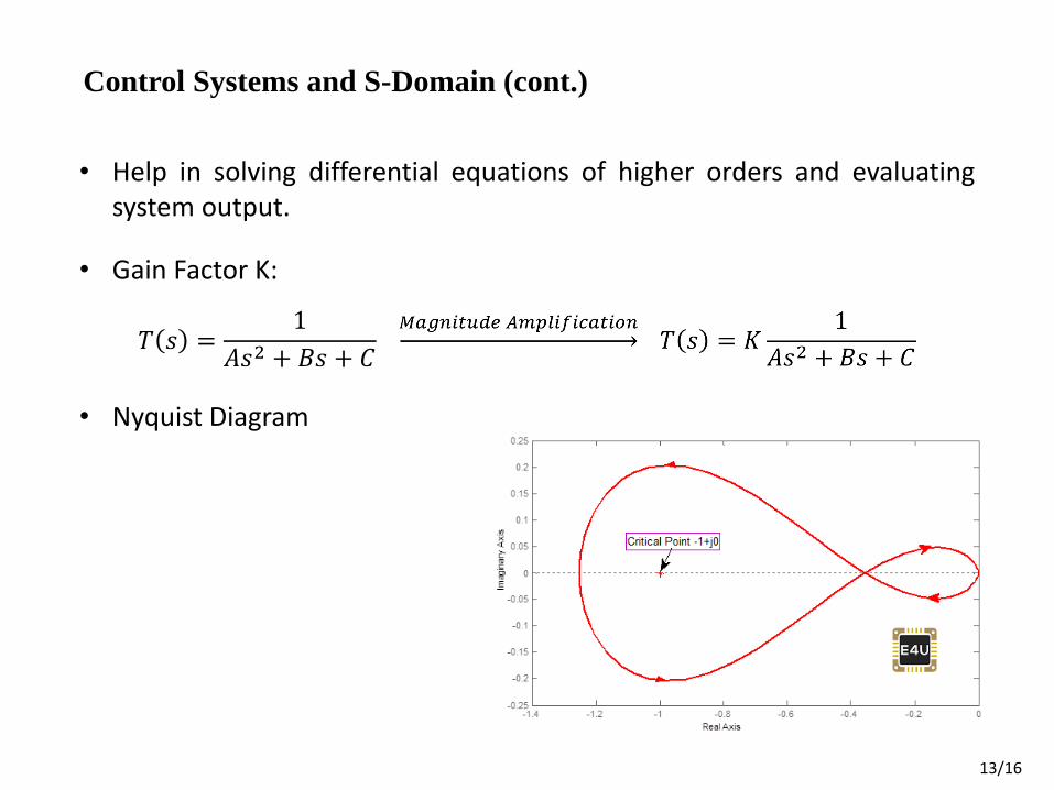
Control Systems and S-Domain (cont.)
13/16
• Gain Factor K:
• Nyquist Diagram
𝑇 𝑠 =1
𝐴𝑠2 + 𝐵𝑠 + 𝐶
• Help in solving differential equations of higher orders and evaluating system output.

Control Systems and S-Domain (cont.)
14/16
Picture Source: 2010218 (Linear System and Control) at University of Sistan and Baluchestan, Semester 3981, Midterm Exam, by Dr.
Saeed Tavakoli Afshari.

Control Systems and S-Domain (cont.)
15/16
• Faster forecasting of the outputs of a system.
Picture Source: (1) https://en.m.wikipedia.org/wiki/Aircraft_flight_control_system (2) https://lancmoms.com/adaptive-cruise-control/

The END!