Embed Size (px)
Citation preview
7/27/2019 AStandard Test Method for Tensile Properties of Geotextiles by the Wide-Width Strip Method
http://slidepdf.com/reader/full/astandard-test-method-for-tensile-properties-of-geotextiles-by-the-wide-width 1/39
4m Designation: D 4595 - 86
Standard Test Method for
Tensile Properties of Geotextilesby
the Wide-Width Strip
Method1
Thia rundvd is iuud under rhc fixed designation D 4595; the nurnkr immediately following rhc designation indicates rhe year oforiginal adopdon or. in the cue of .&on. rhe year o f hsx mis ion . A number inparrnrhaa iadicafurhe year of kst reapproval. A
nrpncript epsilon (r ) indifata an editorial change Jincc the 1 m i s i o n or rcrpproval
' I. Scope'
1.1 This test method covers the measurement of tensile
properties of geotextiles using a wide-width strip specimen
tensile method. This test method is applicable to mostgeotextiles that include woven fabrics, nonwoven fabrics,layered fabrics, knit fabrics, and felts that are used for
geotextile application.1.2 This test method covers the measurement of tensile
strength and elongation of geotexriles and includes directions
for the caIculation of initial modulus, o f k t modulus, ecantmodulus, and breaking toughness.
1.3 Procedures for measuring the tensile properties of
both conditioned and wet geotextiles by the wide-width strip
method are included.1.4 The basic distinction between this test method and
other methods for measuring strip tensile properties is the .width of the specimen. This width, by con- is greaterthan the length of the specimen. Some fabrics used ingmtextile applications have a tendency to contract (neck
down) under a force in the gage length area. The greater
width of the specimen specified in this test method mini-mizes the contraction effect of those fabrics and provides a
closer relationship to expected geotextile behavior in the fieldand a srandard comparison.
1.5 This standard m ay involve ha,-ardoous materials , oper-ations, and equ ipm ent. This standard does not purport toaddress all of the safety problems associated with its use. It isthe responsibility of whoever uses th is standard to consult andestablish appropriate safery and health practices and deter-mine the applicability of reguiatory limitation s prior to use.
2. Referenced Documents
'2.1 ASTM Standards:D76 Specification for Tensile Testing Machines for
TextilesL3
D 123 Definitions of Terms ReIating to Textilesz.'D 579 Specification for Greige Woven Glass Fabrics3D 776 Ractice for Conditioning Textiles for ~ e n g ~ ~ ~
D 905 Practice for Statements on Number of Specimens
for Textiles2D 4439 Terminology for Geosynthetics4-ThL test mahod b under the jurisdiction of ASTM Cornmince D 3 5 on
%thetics and is the dLecl responsibility of Subcornmincc D35.01 on
M-ni~al Properties.
CUiTeacedition appmvcd SzpL 24. 1986. PublirhalNovember 1986.
'Ann& BookofAST,W
Smdards. Vol07.01.
Ann& Book of AST,U Standards. Voi 07.02.'Ann& Rook ofAS.U tandnrds. Vol04.08.
3. Terminology
3.1 armospherefor testing geotexriles, n.-air maintained
at a relative humidity of 65 k 5 % and a temperature of2 1 -c
2.C (70 + 4'F).3.2 breaking toughness, T , (FL"), Jm'*, n.-for
geotextiles, the actualwork-to-break per unit surfacearea ofmaterid.
3.2.1 Discussion-Breaking toughness is proportional to
the area under the force - elongation curve from the originto the breaking point (see also work-to-break). Breaking
toughness is calculated &om work-to-break, gage length, and
width of a specimen.3.3 corresponding orce, Fc, .-the force associated with
a specific elongation on the force-per-unit-width strain curve.
(Syn. oad at specdied elongatian, LASE.)3.4 geotechnicai engineering, n.-the engineering applica-
tion of geotechnics.
3.5 geotechnics. n.-the application of scientific methods
and engineering principles to the acquisition, interpretation,
and use of knowledge of materials of the earth's crust to the
solution of engineering problems.3.5.1 Discussion-Geotechnics embraces the fields of soil
mechanics, rock mechanics, and many of the engineering
aspects of geology, geophysics, hydrology, and related sci-ences.
3.6 geotextile, n.-any permeable textile materiai used
with foundation, soil, rock, earth, or any other geotechnical
engineering related material, as an integral part of a man-
made project, structure, or system.
3.7 initial tensile modulus, J,. (FL"), N m- I, n.-forgeotextiles, the ratio of the change in tensile force per unit
width to a change in strain (slope) of the initial pomon of a
force per unit width strain curve.
3.8 offset tensile mo d u l ~ ~ ~ ,,, (FL"), ~ m " , n.-forgeoteniles, the ratio of the change in force per unit width to
a change in strain (slope) below the proportional limit point
and above the tangent point on the force- longation curve.
3.9 proportional limit,,n.-the greatest stress which a
material is capable of sustaining without any deviation from
proportionality of stress to strain (Hooke's law).
3.10 secant tensile modulus. J , (FL"), Nm", n.-forgeotextiles, the ratio of change in force' per unit width to achange in strain (slope) benveen two points on a force per
unit width suain curve.3.1 1 tangent point, n.-for geote xtiles, the first point of
the force - elongation curve at which a major decrease in
slope occurs.
3.1 1. I Dismsion-The tangent point is determined bydrawing a tangent line passing through the zero axis and the
7/27/2019 AStandard Test Method for Tensile Properties of Geotextiles by the Wide-Width Strip Method
http://slidepdf.com/reader/full/astandard-test-method-for-tensile-properties-of-geotextiles-by-the-wide-width 2/39
proportional elastic limit. The point from the zero force axisthat the force - elongation curve first touches that rangentline is the tangent point.
3.12 tensile modulus, J, (FL-I), m", n.-for geotextiles,the ratio of the change in tensile force per unit width to acorresponding change in strain (slope).
3.13 tensile strength, n.-for geotextiles, the maximumresistance to deformation developed for a specific materialwhen subjected to tension by an external force.
3.13.1 Discussion-Tensile strength of geotextiles is thecharacteristic of a sample as distinct from a specimen and isexpressed in force per unit width.
3.14 tensile test, n.-in textiles, a test in which a textilematerial is stretched in one direction to determine the force- elongation characteristics, the breaking force, or thebreaking elongation.
3.1 5 wide- width strip tensile test, n.-for geotextiles, auniaxial tensile test in which the entire width of a 200-mm(8.0-in.) wide specimen is gripped in the clamps and the gagelength is 100 mm (4.0 in.).
3.16 work-to-break, W, (LF), .-in tensile ~esting, hetotal energy required to rupture a specimen.
3.16.1 Discussion-For geotextiles, work-to-break is pro-portional to the area under the force - elongation curvefrom the origin to the breaking point, and is commonlyexpressed in joules (inch-pound-force).
3.17 yield point, n.-the first point of the force - elonga-tion curve above the proponional (linear) section at whichan increase in elongation occun without a correspondingincrease in force.
3.18 For terminology of other terms used in this testmethod, refer to Terminology D 123 and Terminology
D 4439.
4. Summary of Method
4.1 A relatively wide specimen is gripped across its entirewidth in the clamps of a constant rate of extension (CRE)type tensile testing machine operated at a prescribed rate ofextension, applying a longitudinal force to the specimenuntil the specimen ruptures. Tensile strength, elongation,initial and secant modulus, and breaking toughness of thetest specimen can be calculated from machine scales, dials,recording charts, or an interfaced computer.
5. Significance and Use
5.1 The determination of the wide-width strip force -
elongation propenies of geotextiles provides design parame-ten for reinforcement type applications, for example designof reinforced embankments over soft subgrades, reinforcedsoil retaining walls, and reinforcement of slopes. Whenstrength is not necessarily a design consideration, an alterna-tive test method may be used for acceptance testing. TestMethod D4595 for the determination of the wide-widthstrip tensile properties of geotextiles may be used for theacceptance testing of commercial shipments of geotextilesbut caution is advised since information about between-laboratory precision is incomplete (Note 6). Comparativetests a s directed in 5.1.1 may be advisable.
5.1.1 In cases of a dispute arising from differences inreponed test results when using Test Method D 4595 for
acceprance testing of commercial shipments, the purchaser
and the supplier should conduct comparative tests to deter.mine if there is a statistical bias between their laboratoriQCompetent statistical assistance is recommended forinvestigation of bias. As a minimum, the two parties shouldtake a group of test specimens which are as homogeneousas
possible and which are from a lot of material of the rype ip
question. The test specimens should then be randO ~assigned in equal numbers to each laboratory for testing.n,average results from the two laboratories should be corn-
pared using Student's t-test for unpaired data and a,
acceptable probability level chosen by the two parties befonthe testing began. If a bias is found, either its cause mustfound and corrected or the purchaser and the suppIier mus(agree to interpret future test results in the Iight of the knowbias.
5.2 Most geotextiles can be tested by this test methaSome modification of cIamping techniques may be necessaryfor a given geotextile depending upon its structure. Specialclamping adaptions may be necessary with strong geotexaaor geotextiles made from glass fibers to prevent them from
slipping in the clamps or being damaged as a result of b qgripped in the clamps. Specimen clamping may be modifidas required at the discretion of the individual laboratoryproviding a representative tensile strength is obtained. In any
event, the procedure described in Section 10 of this tcg
method for obtaining wide-width strip tensile strength mugbe maintained.
5.3 This test method is applicable for testing geotextilaeither dry or wet. It is used with a constant rate of extensiontype tension apparatus.
5.4 The use of tensile strength test methods that &a
the clamped width dimension to 50 mm (2 in.) or less, suchas the ravel, cut strip, and grab test procedures, have becD
found less suitable than this test method for detm-miningdesign strength parameters for some geotextiles. ?his k
' particularly the case for nonwoven geotextiles. The wide
width svip technique has been explored by the industry and
is recommended in these cases for geotextile appiications.5.4.1 This test method may not be suited for some woven
fabrics used in geotextile applications that exhibit st rc nmapproximately 100 kN/m or 600 lbf/in. due to clamping andequipment limitations. In those cases, 100-mm (4-in.) widthspecimens may be substituted for 200-mm (8-in.) widthspecimens. On those fabrics, the contraction effect cited in
1.4 is minimal and, consequently, the standard c o m p d ncan continue to be made.
6. Apparatus and Reagents
6.1 Tensile Testing Machine-A constant rate ofsion (CRE)ype of testing machine described in S@*tion D 76 shall be used. When using the CRE type t c dtester, the recorder must have adequate pen response P,properly record the force-elongation curve as @ed 0
SpecificationD 76.6.2 Clamps-The clamps shall be sufficiently wide tod
the entire width of the sample and with appropriate clamp apower to prevent slipping or crushing (damage).
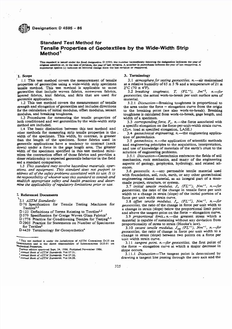
6.2.1 Two basic clamp designs are shown in Figs. 1, 2 9 1
and 4. These designs have been used in the laboratory adhave provided reproducible tensile strengths. These c l ~ p
may be modified to provide greater ease and speed*
7/27/2019 AStandard Test Method for Tensile Properties of Geotextiles by the Wide-Width Strip Method
http://slidepdf.com/reader/full/astandard-test-method-for-tensile-properties-of-geotextiles-by-the-wide-width 3/39
i 50 "
A L L " S T E E L FOR CLAMPS SMALL
BE 01 TOOL STE LL " ALL BOLTS
SMALL BE A- 32s STEEL
1 ALL OIME*SlONS SHALL HAVE A* TOLERA NCE OF 0.01 " MAXIMUM.I AL L A N G L E S SHALL BE 04.
+ . 0 0 2 s 0
WI DE WI DTH TEST CLAMPS
(MAKE 2 C L A Y P S I
FIG. 1 Wide Width Teat Clampa
clamping. In any event, caution mud be taken to ensure thetype material and dimensions of the clamp are adequate forthe user's expected fabric strength.''6.2.2 Size of Jaw Faces-Each clamp shall have jaw facesmeasuring wider than the width of the specimen, 200 mm (8h.),and a minimum of 50-mm (2-in.) length in the directionof he applied force.6.3 Area-Measuring Device-Use an integrating accessory
to the tensile testing machine or a planimeter.6.4 Distilled Waer andNonionic Wetting Agent, for wet
specimens only.
7. Sampling
7.1 Lot Sample-For the lot sample, take rolls ofWtextiles asdirected in an applicable material specification,
as agreed upon between the purchaser and the supplier.
NO= 1-The extent of the sampling for wide-width strip tensileh P e n i a s generally defined in an a p p l i d e order or contract. Amongac options available to the purchaser sand rhe supptia is for the.k h as er t o ac ap t certification by the manufacturer that the materialmqu~stionmeets the rcquiremenrsagreed upon by the two parti- and*t the basis for the anification is, such as, historical data generated
, hm material ma nuf aau nd under the same conditions.
7.2 Laboratory Sample-For the laboratory sample, rakea full-width swatch approximately 1 m (40 in.) long in themachine direction from each roll in the lot sample. Thesample may be taken from the end portion of a roll providedthere is no evidence it is distorted or different from otherponions of the roll. In cases of dispute, take a sample thatwill exclude fabric from the outer wrap of the roll or theinner wrap around the core.
7.3 Test Specimens-For tests in the machine direaionand the cross-machine direction, respectively, take from each
swatch in the laboratory sample the number of specimensdirected in Section 8. Take specimens at random from thelaboratory sample, with those for the measurement of themachine direction tensile propenies from different positionsacross the geotextile width, and the specimens for themeasurement of the cross-machine direction tensile proper-ties from different positions along the length of the geotex-tile. Take no specimens nearer the selvage or edge of thegeotextile than 1/10 the width of the geotextile (see 8.2).
8. Test Specimen Reparation
8.1 Number of Specimens
7/27/2019 AStandard Test Method for Tensile Properties of Geotextiles by the Wide-Width Strip Method
http://slidepdf.com/reader/full/astandard-test-method-for-tensile-properties-of-geotextiles-by-the-wide-width 4/39
ALL STEEL F O R CLLYPS
SHALL B L "01 TOOL S T E I
ALL D lYENSlONS SHALL
WAY A T OL ER AN CE OF
0.01 Y A X I M U Y . A L L
100- ANGLES SHALL BL 14.2 oozs*
Iso-0..
;oJ
SCALE: I * * I l I 2 -
MAKE 2 INSERTS MALL 2 I N S E R T S
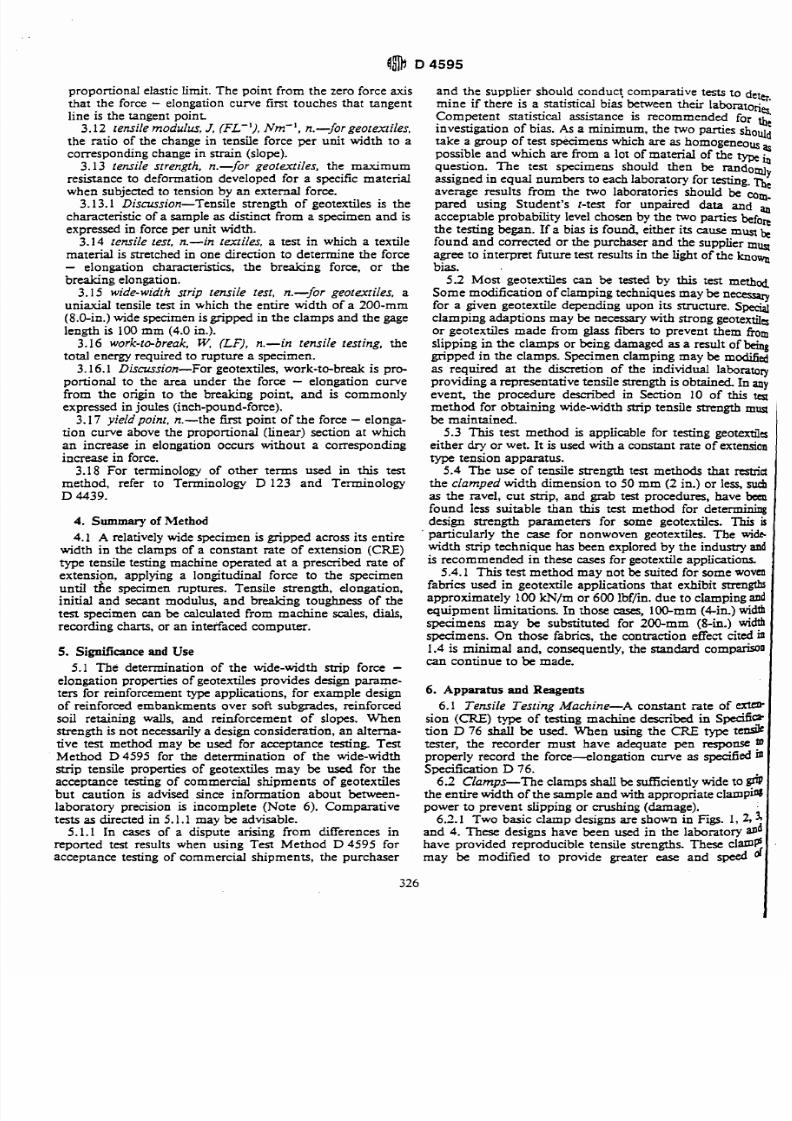
FIG. 2 Insert$ torWide Width Clamps
8.1.1 Unless otherwise agreed upon, as when specified in
an applicable material specification, take a number of
specimens per fabric swatch such that the user may expect atthe95 % probability level that the test result is not more than
5.0 % of the average above or below the true average of theswatch for each, the machine and crossmachine direction,
respectively. Determine the number of specimensas foIlows:
8.1.1.1 Reliable Esfimafe of v-When there is a nliable
estimate of v based upon extensive past records for similar
materials tested in the user's laboratory as directed in the
method, calculate the required number of specimens using
Eq 1,as foIlows:
n = ( t v l ~ ) ~ (1)
where:
n = number of specimens (rounded upward to a wholenumber),
v = reiiable estimate of the coefficient of variation ofindividual observations on similar mareriais in theuser's laboratory under conditions of singleaperatorprecision, %,
r = the value of Student's f for one-sided limits (see TableI), a 95 5% probability level, and the degrees of freedomassociated with the mimate of v, and
A = 5.0 % of the average, the value of the allowablevariation.
8.1.1.2 N o Reliable Esfimafe of v-When there is noreliable estimate of v for the user's laboratory, Eq 1 should
not be used directly. Instead, specify the fixed number of sixspecimens for each the machine direction and the cross-
machine direction tests. The number of specimens is calcu-
lated using v = 7.4 % of the average. This value for v issomewhat larger than usually found in practice. When areliable estimate of v for the user's laboratory becomaavailable, Eq 1 will usually require fewer than the fixednumber of specimens.
8.2 Tesr Specimen Size: s
8.2.1 Prepare each finished specimen 200-mm (8.0.in.) 'wide (excluding fringe when applicable, see 8.2.2) by at ltad <200-mm (8.0-in.) long (see 8.2.2) with the length dimension 2being designated and accurately paralIel to the direction for 4which the tensile strength is being measured. Centrally, drawtwo lines running the full width of the specimen, accurately .<
perpendicular to the length dimension and separatedby 100.2mm 4 in.) to designate the gage area (See Note 6). -3
8.2.2 For some woven geotextils, it may be n to:&cut each specimen 210-mm (8.5-in.) wide and then remove !:
an equal number of yams from each side to obtain the 200 :mm (8.0 in.) finished dimension. This helps mainrain.. .f
specimen integrity during the test.
8.2.3 The length of the -men depends upon theW ' ;of clamps being used. It must be long enough to exten*
through the full length of both clamps, as determined fo rbe ,
direction of test
8.2.4 When specimen integrity is not affected, the sped' ,
mens may be initially cut to the finished width. I
7/27/2019 AStandard Test Method for Tensile Properties of Geotextiles by the Wide-Width Strip Method
http://slidepdf.com/reader/full/astandard-test-method-for-tensile-properties-of-geotextiles-by-the-wide-width 5/39
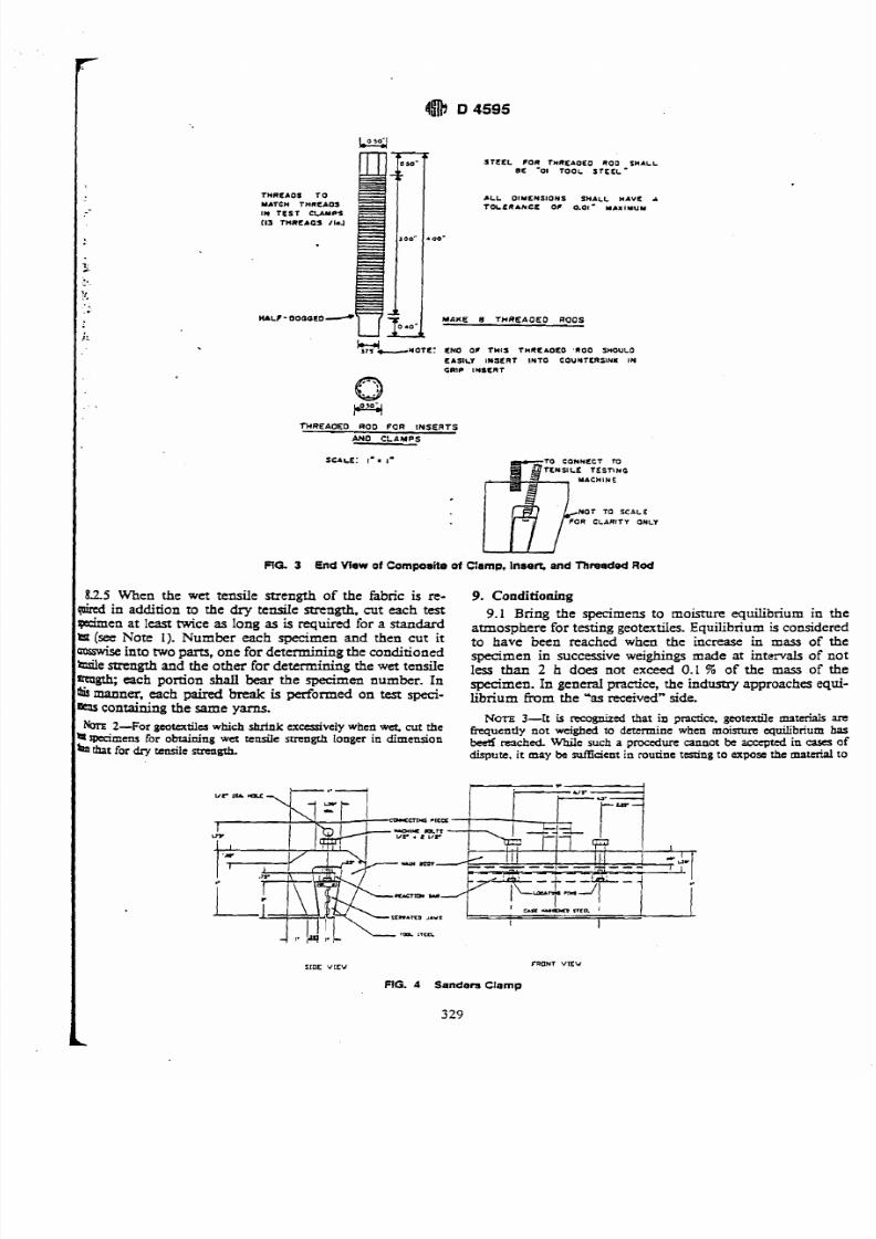
STE EL COR THREAOEO ROO-SMA LLBC ' 01 TOOL STE EL
T H R C A O S T O A L L O l Y L N S l O N S S H A LL M A V E r
MATCH THRCAOS T O L E R A N C E O C 0 . 0 1 - YAXIYUMI N T E S T C LA M P$
(13 T M R C A 4 J /laJ
00 -
MAKE 8 THREAOEO ROOS
k?!-NOTC: CNO OC T H IS TM RE AOE O 'ROO S MOULO
E A S IL Y I N S E R T I N T O C O U N T E R S I N I I N
G R I P I N S C R T
THREAOEO ROD FO R INSERTS
A N 0 C L A M P S
SCALE: 1. I- T rojncc~C N S I L l T E S T I N G
MACMINE
NOT TO SCALE
FOR CLARITY ONLY
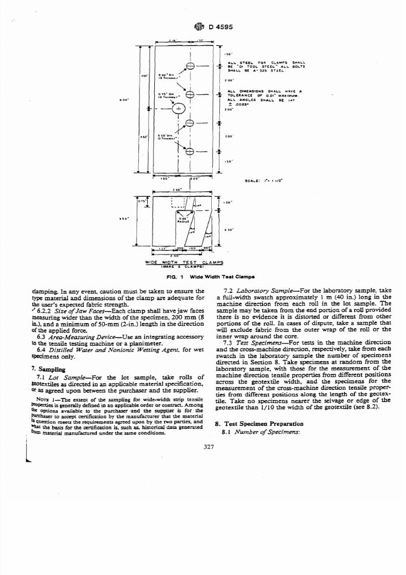
FiG. 3 End View of Composite of Clamp. Inaeh and Thmded RodI
1.2.5 When the wet tensile strength of the fabric is re-
wired in addition to the dry tensile strength, cut each test
Ipedmen at leas mice as long as is required for a standard
ht (see Note 1). Number each specimen and then cut it
asswise into two parts, one for determining the conditionedWe strength and the other for determining the wet tensile
mgth;each pomon shall bear the specimen number. Inmanner, each paired break is performed on test speci-containing the same yarns.
Ih -For gcotextilcs which shrink excessively when wet, cut thea rpcimens for obtaining wet tensile Rnngrh Longer in dimension
that for dry tensile strength.
9. Conditioning
9.1 Bring the specimens to moisture equilibrium in the
atmosphere for testing geotextiles. Equilibrium is considered
to have been reached when the increase in mass of thespecimen in successive weighings made at intervals of not
less than 2 h does not exceed 0.1 % of the mass of the
specimen. In general practice, the industry approaches equi-librium from the ' as received" side.
NOTE 3-It is recognized hat in pncfice. gcotcxtilc materials are
frrqucntly not weighed to dcrcrmine when rnoisrurc equilibrium hasb e d reached WhiIc such a procedure cannot be accepted in cass of
dispute, it may be d c i c n t n routine testing to expose rhe material to
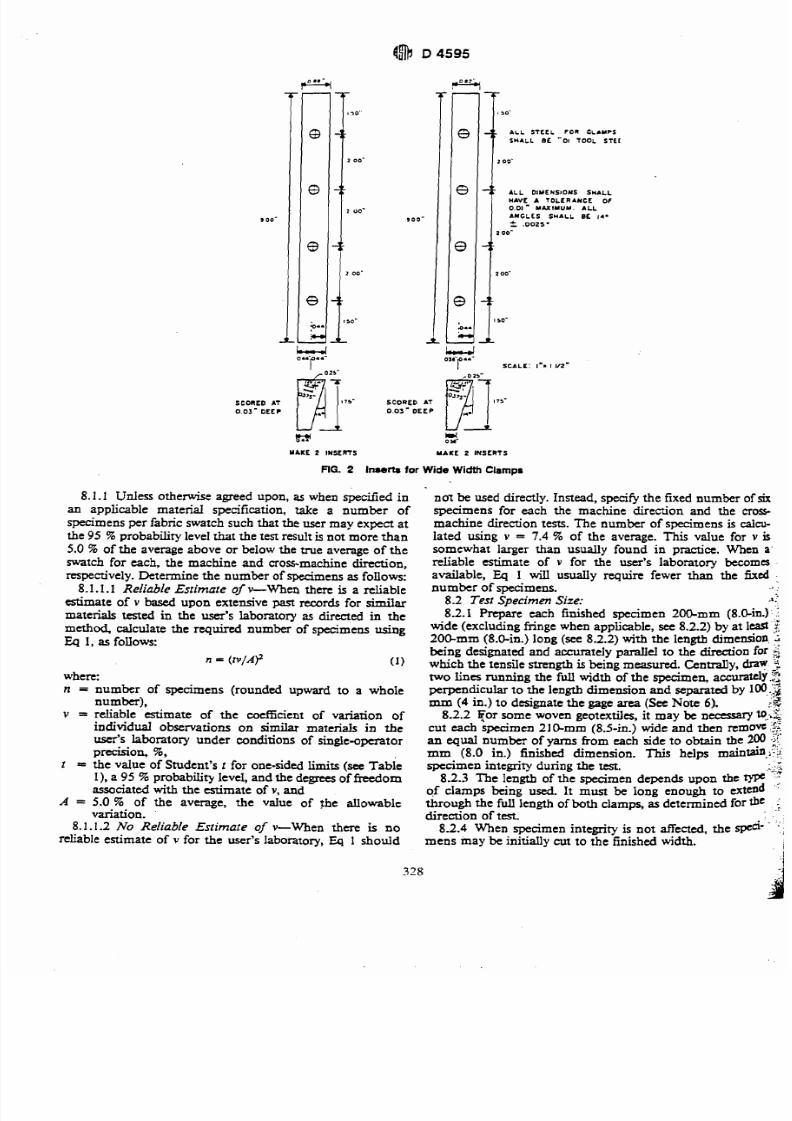
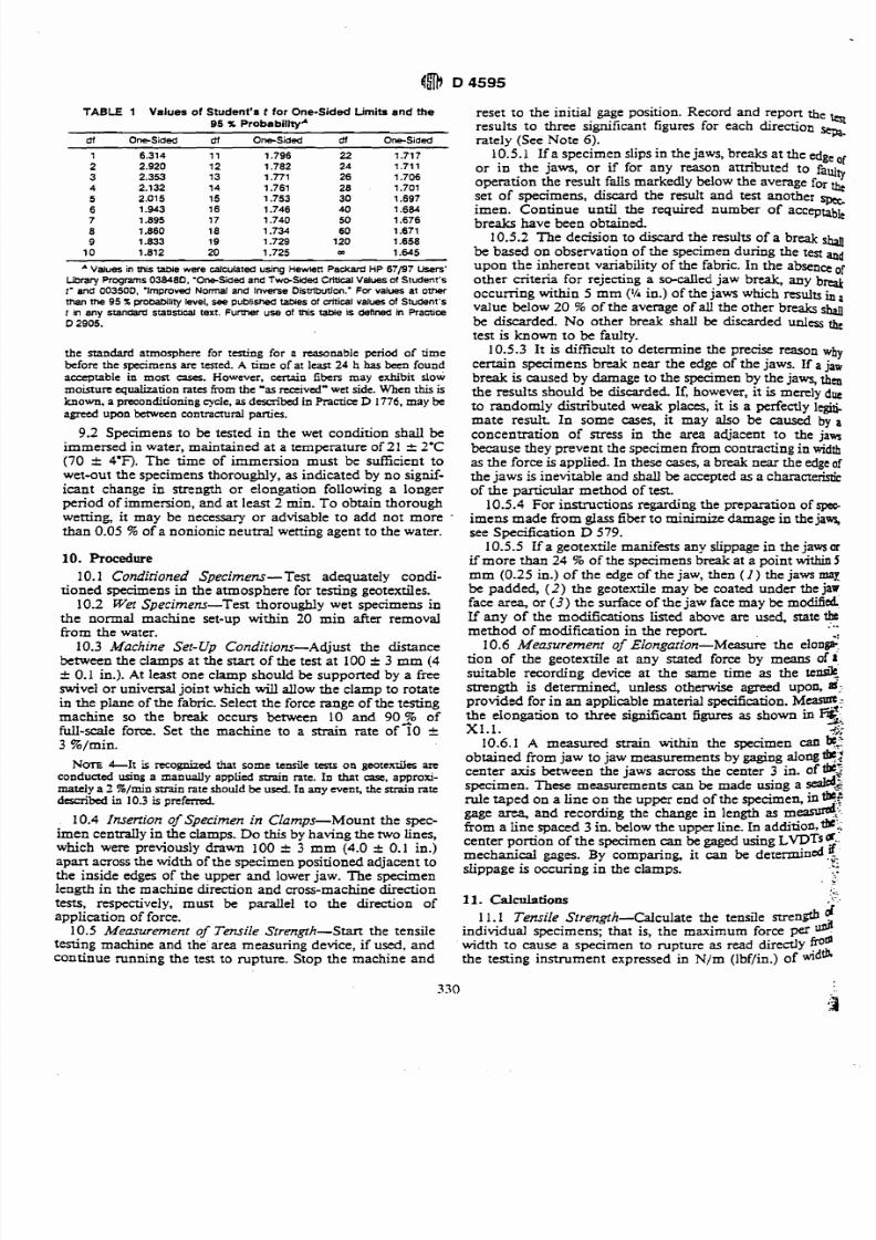
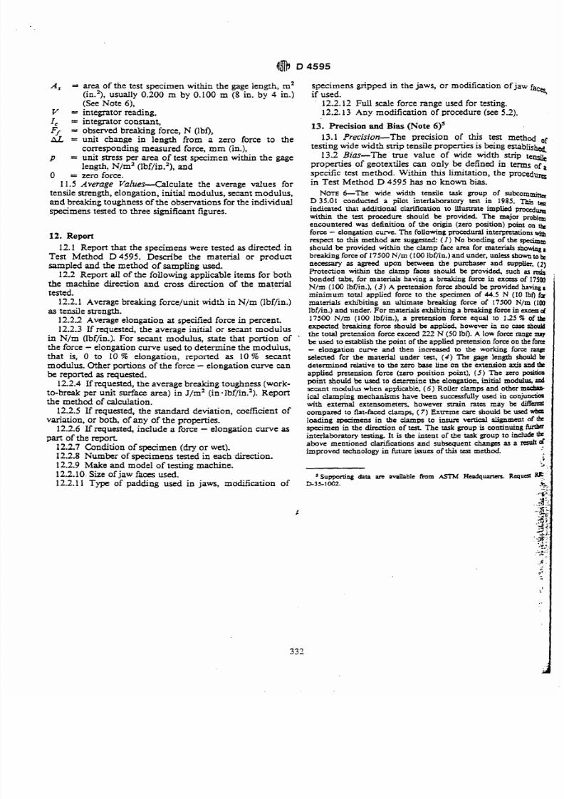
SIDE V I E V FRONT VlEV
FiG. 4 Sandem Clamp
7/27/2019 AStandard Test Method for Tensile Properties of Geotextiles by the Wide-Width Strip Method
http://slidepdf.com/reader/full/astandard-test-method-for-tensile-properties-of-geotextiles-by-the-wide-width 6/39
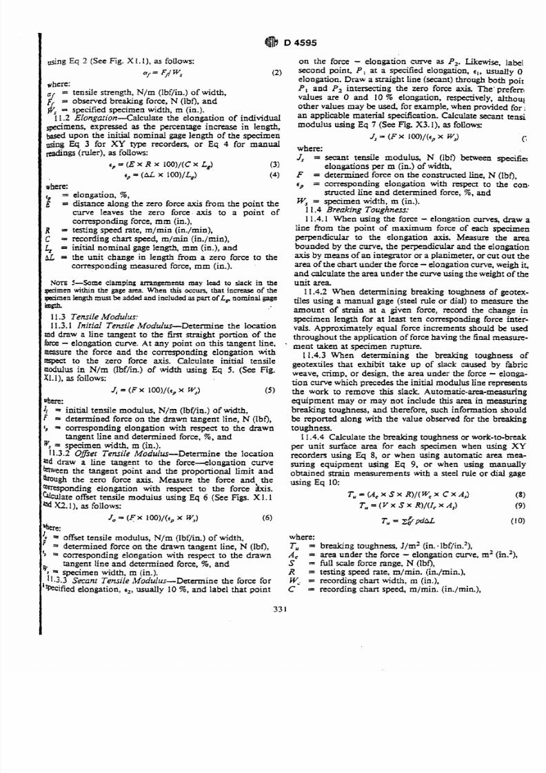
TABLE 1 Values of Student's t tor One-Sided Limits and me
95 % ProbabilttyA
df Omsided 61 One-sided 61 One-sided
* Values in this taMe were calculated using Hewlen Packad HP 67/97 Usen'
Library Programs038480, 'One-Sded andT w ~ S i e d riticalValuesof Student'sr' and 00350D. 'Improved Normal and Inverse Distribution.' For values at oUmman me 95 % probabili level, see published W e s of critical values of Student'st in any standard statistical text. F u m r use of this table is defined in PracticeD 2905.
the standard atmosphen for tming for a reasonable period of timebefore the specimens arc tested. A rime o f at least 24 h has been found
acceptable in most cases. However, ccnain fibers may exhibit slowmoisture equalization ra ts from the 'as received" wet side . When this isknow n, a p reconditioning cycle,as described in Pracria D 1776,may beagreed upon betwan mntractural panics.
9.2 Specimens to be tested in the wet condition shall beimmersed in water, maintained at a temperature of 21 2 2'C(70 r 4'F). The time of immersion must be suilicient towet-out the specimens thoroughly, as indicated by no signif-icant change in strength or elongation following a longerperiod of immersion, and at least 2 min. To obtain thoroughwetting, it may be necessary or advisable to add not morethan 0.05 5% of a nonionic neutral wetting agent to the water.
10. Procedure
10.1 Conditioned Specimens- Test adequately condi-tioned specimens in the atmosphere for testing geotextiles.
10.2 Wet Specimens-Test thoroughly wet specimens inthe normal machine set-up within 20 min after removalfrom the water.
10.3 Machine Set-Up Conditions-Adjust the distancebetween the clamps at the star^ of the test at 100 -c 3 mm (4r 0.1 in.). At Ieast one clamp should be supported by a free
swivel or u n i v e d joint which will allow the clamp to rotatein the plane of the fabric. Select the force range of the testingmachine so the break occurs between 10 and go2 offull-scale force. Set the machine to a strain rate of 10 23 %/min.
NOTE &It is recognized that some tensile tsu on geotexrilts ~ T C
conducted using a manually applied suain rate. In that case, approxi-mately a 2 %/min main rate should be used. In any event, the mai n ratedescribed in 10.3 is p n f tm d .
10.4 Insenion o Specimen in Clamps-Mount the spec-imen centrally in the clamps. Do this by having the two lines,which were previously drawn 100 r 3 mm (4.0 zk 0.1 in.)apart across the width of the specimen positioned adjacent tothe inside edges of the upper and lower jaw. The specimenlength in the machine direction and cross-machine directiontests, respectively, must be parallel to the direction ofapplication of force.
10.5 Measurement o Tensile Strength-Start the tensile
testing machine and the area measuring device, if used, andcontinue running the test to rupture. Stop the machine and
reset to the initial gage position. Record and report the tstresults to three significant figures for each direction se;rarately (See Note 6).
10.5.1 If a specimen slips in the jaws, breaks at the edgeofor in the jaws, or if for any reason attributed to faul
tYoperation the result fails markedly below the average forset of specimens, discard the result and test another specimen. Continue until the required number of acceptabbreaks have been obtained.
10.5.2 The decision to discard the results of a breakbe based on observation of the specimen during the testupon the inherent variability of the fabric. In the absenceofother criteria for rejecting a so-called jaw break, anybwoccurring within 5 mm (' h in.) of the jaws which resultsh avalue below 20 % of the average of all the other breaksbe discarded. No other break shall be discarded unlw the
test is known to be faulty.10.5.3 It is difilcult to determine the precise reason why
certain specimens break near the edge of the jaws. If a jaw
break is caused by damage to the specimen by the jaws, thmthe results should be discarded If, however, it is merely due
to randomly distributed weak places, it is a perfectly legit^
mate result. In some cases, it may also be caused by a
concentration of mess in the area adjacent to the j a ~because they prevent the specimen from contracting in width
as the force isapplied. In these cases, a break near the edgeof
the jaws is inevitable and shall be accepted as a characteristicof the particular method of test.
10.5.4 For instructions regarding the preparation of speoimens made from gIass fiber to minimize damage in the jam,see Specification D 579.
10.5.5 If a geotextile manifest. any slippage in the jaws orif more than 24 9% of the specimens break at a point within5mm (0.25 in.) of the edge of the jaw, then ( I ) he jaws may,be padded, ( 2 ) he geotexrile may be coated under the jawface area, or (3) he surface of the jaw face may be modifiedIf any of the modifications lined above are used, state the
method of modification in the report. -
10.6 Measurement o ~l on ~a ri on -~ ea su rhe elon&tion of the geotextile at any stated force by means of?suitable recording device at the same time as the tendk_
strength is determined, unless otherwise agreed upon, sr.provided for in an applicable material specification. M e q :the elongation to three significant figuns as shown in2,:X1.1. ..A
10.6.1 A measured strain within the specimen can &,
obtained from jaw to jaw measurements by gaging alonge:center axis between the jaws across the center 3 in. ofspecimen. These measurements canbe made using a d42rule taped on a line on the upper end of the specimen, in*!gage area and recording the change in length as m d :from a line spaced 3 in. below the upper line. In additio&*-.center portion of the specimen canbe gaged usingLVDT ~ ~ -
ifmechanical gages. By comparing, it can be determined,,slippage is occuring in the clamps. .I
a -1 1. Calculations
11.1 Tensile Strength-Calculate the tensile strength dindividual specimens; that is, the maximum force per ud
width to cause a specimen to rupture as read directlyp'the testing instrument expressed in N/m (lbf/in.) of wdfb
7/27/2019 AStandard Test Method for Tensile Properties of Geotextiles by the Wide-Width Strip Method
http://slidepdf.com/reader/full/astandard-test-method-for-tensile-properties-of-geotextiles-by-the-wide-width 7/39
using Eq 2 (See Fig. X 1. I ) , as follows: on the force - elongation curve as P,. Likewise, label
a/= F/1Ws (2) second point. P , at a specified elongation, c, , usually 0
elongation. Draw a d g h t ine (secant) through both poirwhere:
= tensile strength, N/m (Ibflin.) of width,P, and P2 ntersecting the zero force axis. The' prefem,
ff = observed breaking force, N (lbf), andvalues are 0 and 10 % elongation, respectively, althouI
ys= specified specimen width, m (in.).other values may be used, or example, when provided for i
11.2 Elongation<alculate the elongation of individual an applicable material s ~ e c i f i ~ t i ~ n -alculate secant tensi&mens, expr-d as the percentage inc- in length, modulus using Eq 7 (See Fi'ig. X3-11,as follows:
&d upon the initial nomind gage length of the specimen
d g q 3 for XY type recorders, or Eq 4 for manuald n g s ruler), as follows:
e = ( E x R x IOO)/(Cx L,) (3)
ep = (ar.x 100)lLg) (4)
where:tg = elongation, %,
E = distance along the zero force axis from the point thecurve leaves the zero force-axis to a point of
corresponding force, mm (in.),
R = testing speed rate, m/ min (in./min),
C = recording chart speed, m/min (in./min),
L, = initial nominal gage length, mm (in.), and
LL = the unit change in length from a zero force to thecorresponding measured force, mm (in.).
N m -Some clamping arrangem ents may lead to slack in the@men withrn the gage a r a When this occurs, that increase of rhe
rpsimen length mustbe addedand included as part of L, nominal gage
kgth.
11.3 Tensile Modulus:11.3.1 Initial Tensile Modulus-Determine the location
and draw a line tangent to the first straight pomon of theforce - elongation c w e . At any point on this tangent line, -measure the force and the corresponding elongation withrapect to the zero force axis. Calculate initial tensile
modulus in N/m (Ibflin.) of width using Eq 5. (See Fig.X1.1), as follows:
r, = (F 100)/(tpx Ws) ( 5 )
ere:
4 = initial tensile modulus, N/m (lbf/in.) of width,F = determined force on the drawn tangent line, N (Ibf),
5 = corresponding elongation with respect to the drawntangent line and determined force, %, and
W, = specimen width, m (in.).11.3.2 Offset Tensile Modulus-Detennine the location
ad draw a line tangent to the force--elongation curve
b e e n the tangent point and the proportional limit andbough the zero force axis. Measure the force and the
mmponding elongation with respect to the force his.Calculateoffset tensile modulus using Eq 6 (See Figs. X 1.1
Qda. ), as follows:
J, = (F 100)/(cpx W,) (:
where:
Js = secant tensile modulus, N (Ibf) between specifiaelongations per m (in.) of width,
F = determined force on the constructed line, N (Ibf),
c p = corresponding elongation with respect to the con.structed line and determined force, %, and
W,= specimen width, m (in.).1 1.4 Breaking Toughness:
1 1.4.1 When using the force - elongation curves, draw a
line from the point of maximum force of each specimen
perpendicular to the elongation axis. Measure the areabounded by the curve, the perpendicular and the elongation
axis by means of an integrator or a planimeter, or cut out the
area of the chart under the force- longation curve, weigh it,
and calculate the area under the c w e using the weight of the
unit area
11.4.2 When determining breaking toughness of geotex-
tiles using a manual gage (steel rule or dial) to measure the
amount of strain at a given force, record the change in
specimen length for at least ten corresponding force inter-
vals. Approximately equal force increments should be used
throughout the application of force having the final measure-
ment taken at specimen rupture.
11.4.3 When determining the breaking toughness ofgeotextiles that exhibit take up of slack caused by fabric
weave, crimp, or design, the area under the force - elonga-
tion curve which precedes the initial modulus line represents
the work to remove this slack Automatic-area-measuring
equipment may or may not include this area in measuring
breaking toughness, and therefore, such information should
be reported along with the value observed for the breaking
toughness.
11.4.4 Calculate the breaking toughness or work-to-break
per unit surface area for each specimen when using X Yrecorders using Eq 8, or when using automatic area mea-
suring equipment using Eq 9, or when using manually
obtained strain measurements with a steel rule or dial gageusing Eq 10:
T,= (A , x S x R)/(W, x C x A,) (8)
T,= ( Vx S x R)/(I,x A 3 (9)
'0 ' ff& tensile modulus, N/m (Ibflin.) of width, where:
determined force on the drawn tangent line, N (lbf), Tu = brehng toughness. Jlm' (in--lbf/in.2),'J ' orresponding elongation with respecf to the drawn A, = area under the force - elongation curve, m2 (inV2),
tangent line and determined force, %, and S = full scale force range, N (Ibf),
specimen width. m (in.). R = testing speed rate, m/rnin. (in./min.),
1l1.3.3 Secant Tensile ~Wodulus-Determine the force for Wi = recording chart width. rn (in.),
%cified elongation, c usually 10%, and label that point C=
recording chart speed, m/min. (in./min.),
7/27/2019 AStandard Test Method for Tensile Properties of Geotextiles by the Wide-Width Strip Method
http://slidepdf.com/reader/full/astandard-test-method-for-tensile-properties-of-geotextiles-by-the-wide-width 8/39
A, = area of the test specimen within the gage length, rn2 specimens gripped in the jaws, or modification of jaw f
(in.2), usually 0.200 m by 0.100 m (8 in. by 4 in.) if used.(See Note 6), 12.2.12 Full scale force range used for testing.
V = integrator reading. 12.2.13 Any modification of procedure (see 5.2).
I, = integrator constant,Ff = observed breaking force, N (lbf),AL. = unit change in length from a zero force to the
corresponding measured farce, mm (in.),p = unit stress per area of test specimen within the gage
length, N/m2 (1bf/h2), and0 = zero force.
11.5 Average Values--Calculate the average values fortensile strength, elongation, initial modulus, se&t modulus,and breaking toughness of the observations for the individualspecimens tested to three significant figures.
12 . Report
12.1 Report that the specimens were tested as directed inTest Method D 4595. Describe the material or productsampled and the method of sampling used.
12.2 Report all of the following applicable items for boththe machine direction and cross direction of the matenaltested.
12.2.1 Average breaking force/unit width in N/m (Ibflin.)as tensile strength.
12.2.2 Average elongation at specified force in percent.12.2.3 If requested, the average initial or secant modulus
in N/m (Ibf/in.). For secant modulus, state that portion of 'the force - elongation curve used to determine the modulus,that is, 0 to 10% elongation, reported as 10% secant
modulus. Other portions of the force-
elongation curve canbe reported as requested.
12.2.4 Ifrequested, the average breaking toughness (work-to-break per unit surface area) in ~ / r n ~in.lbf/in.2). Reportthe method of calculation.
12.2.5 If requested, the standard deviation, coefficient ofvariation, or both, of any of the properties.
12.2.6 Ifrequested, include a force - elongation curve aspa^ of the report.12.2.7 Condition of specimen (dryor wet).12.2.8 Number of specimens tested in each .direction.12.2.9 Make and model of testing machine.12.2.10.Size of jaw faces used12.2.1 1 Type of padding used in jaws, modification of
13. Precision and Bias (Note 6)5
13.1 Precision-The precision of this test methodtesting wide width strip tensile properties is being estabIished
13.2 Bias-The true value of wide width strip tewproperties of geotextiles can only be defined in termssped% test method. Within this limitation, the procedurein Test Method D 4595 has no known bias.
NOTE &The wide width tensile task group of subcomm&D 35.01 conducted a pilot interlaboratory test in 1985.
tPindicated that additional clarification to illusuate implied prowurawithin the test procedure should be provided. The major problmencountered was definition of the origin (zero position) point onforce - dongation curve. The ollowing procedural interpretationsrespect to this method arc suggest& ( I No bonding of the s p h Qshould be provided within the damp face a m or materials showingbreaking force of 17500N/m (100 lbflin.) and under. unless shownu,nefcrsary as agreed upon between the purchaser and supplier, ( 2 )
Proteaion within the clamp f aa s should be provided, such as ndp ,
bonded tabs, for materials having a breaking force in exass of 17500N/m (100 Ibflin.), (3)A pretension force should be provided having 1minimum total applied force to the specimen of 44.5 N (10 Ibf) famaterials exhibiting an ultimate breaking force of 17500 N/m (100Ibflin.) and under. For materials exhibiting a braking for= in ucasd17500 N/m (100 Ibflin.), a pretension force qua1 to 12 5 % of the
expmed breaking force should be applied, however in no case shoukithe total pretension force excecd 222 N (50 Ibf).A low force range mybe used to establish the point of the applied pretension force on the fom- elongation curve and then i n d o the working fonrselecrcd for the m a t 4 under tat, (4 ) The gage length should k *
determined d at iv e to the zero base line on the extension axis and tkapplied pretension force (zero position point). (5)The zero p&
point should be used to determine the elongation, initial modulus,adsecant modulus when applicable. ( 6 ) Roller clamps and other rn-ical clamping mechanisms have been succssfully used in conjun&o~with external extensomam, however d n ates may be d i f f mcompared to fl at -f ad clamps, ( 7) Extreme care should be used wbm
loading specimens in the clamps to insure vertical alignment of*specimen in the direction of tcst The task group is continuing I%
interlaboratory tcsring. It is the intent of the task group to indude*above mentioned darificadons and subsequent changes as aimproved technology in future issues of this tea method.
. +
' upponing data are available from ASIM Hudquanm R q u s l '. I
7/27/2019 AStandard Test Method for Tensile Properties of Geotextiles by the Wide-Width Strip Method
http://slidepdf.com/reader/full/astandard-test-method-for-tensile-properties-of-geotextiles-by-the-wide-width 9/39
APPENDIX
(Nonmandatory Information)
XI. INITIAL GEOTEXTILE TENSILE MODULUS
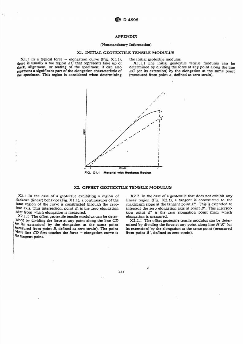
X 1.1 In a typical force - elongation curve (Fig. X 1. I ) , the initial geotextile modulus.there is usually a toe region AC that represents take up of X 1.1.1 The initial geotextile tensile modulus can be
$lack, alignment, o r seating of the specimen ; it can also determined by dividing the force at any point along the linenprese nt a significant part of the elongation characteristic of AG (or its extension) by the elongation at the same pointb e specimen. This region is considered when d eterm ining (measured from point A, defined as zero strain).
RG. X1.1 Material with Hoakean Region
X2. OFFSET GEOTEXTILE TENSILE M ODUL US
X2.1 In the case of a geotextile exhibiting a region ofHookean (linear) behav ior (Fig. X 1.1 ), a continuation o f thebear region of the curve is constructed through the zero-force axis. This intersection, p oint B, is the zero elongationPoint from which elongation is measured.a.. I The offset geotextile tensile mod ulus can be deter-
! mined by dividing the force at any point along the line CD
(Or its extension) by the. elongation at the same point("mured from point B, defined as zero strain).The point%ere line CD first touches the force - elongation curve is
tangent point.
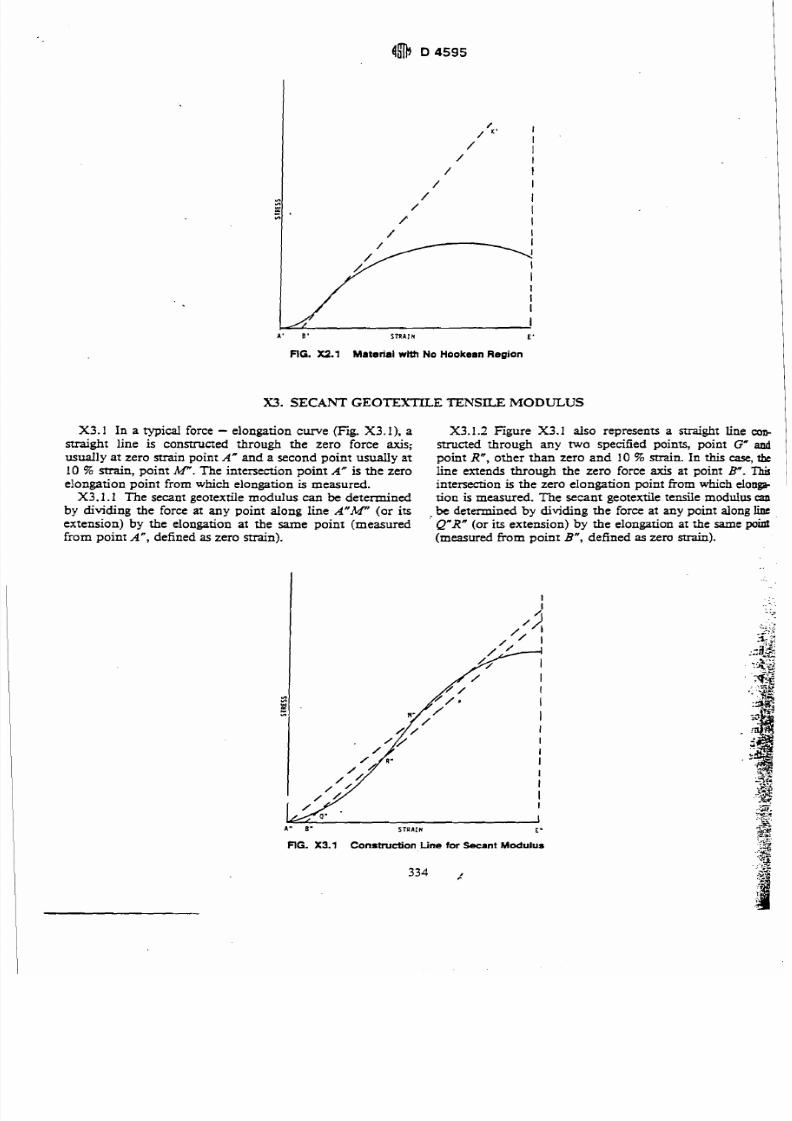
X2.2 In the case of a geotextile that does n ot exhibit anylinear region (Fig. X2.1), a tangent is constructed to themax imum slope at the tangent point H'. This is extended tointersect the zero elongation axis at point B'. This in tem c-tion point B' is the zero elongation point from whichelongation is measured.
X2.2.1 Th e offset geotextile tensile mod ulus can be deter-mine d by dividing the force at any point along line H'K' orits extension) by the elongation at the same point (measuredtiom point B', defined as zero strain).
7/27/2019 AStandard Test Method for Tensile Properties of Geotextiles by the Wide-Width Strip Method
http://slidepdf.com/reader/full/astandard-test-method-for-tensile-properties-of-geotextiles-by-the-wide-width 10/39
A ' 6 ' STRAIN E '
FIG. X2.1 Material with No Hookean Region
SECANT GEOTEXTILE TENSILE MODULUS
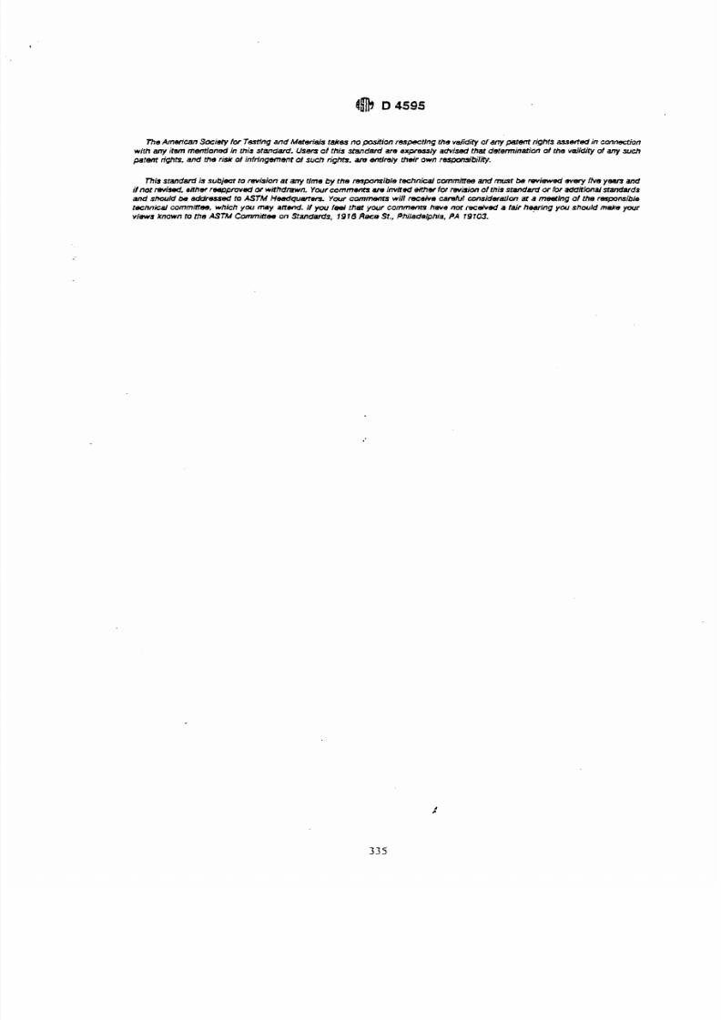
X3.1 In a typical force - elongation c w e (Fig. X3.1), a
straight line is constructed through the zero force axis;
usually at zero strain point A" and a second point usually at
10 % main, point h4".The intersection point A" is the zero
elongation point from which elongation is measured.
X3.1.1 The secant geotextile modulus can be determined
by dividing the force at any point along lineA"W
(or itsextension) by the eIongation at the same point (measured
from point A", defined as zero strain).
X3.1.2 Figure X3.1 also represents a straight line copstructed through any two specified points, point G" andpoint R", other than zero and 10% strain. In this case, the
line extends through the zero force axis at point B". Thisintersecrion is the zero eIongation point from which elongb
tion is measured. The secant geotextile tensile modulus can.be determined by dividing the force at any point along lineQ"R" or its extension) by the elongation at the same p o d(measured from point B", defined as zero strain).
Am 8- STRAIN E
FIG. X3.1 Constnrction Line tor Secant Modulus
7/27/2019 AStandard Test Method for Tensile Properties of Geotextiles by the Wide-Width Strip Method
http://slidepdf.com/reader/full/astandard-test-method-for-tensile-properties-of-geotextiles-by-the-wide-width 11/39
TheAmerican ociefy lor T&ng and Materiels takes no -on respecting the valid0 of any patent rights =&ad in connecri'onwith any t m memloned in this standard. Users of this standard are expr(~stlyadvised that determination of the velidily d ny suchpatem rights. and the risk of intrlngement of such fights, am emlrely their awn resm.bili ly.
mi$ standardis sub jar to revision at any tlme by the r(~ponsib1eechnical commHee and must be reviewedwery fhe y e am and
Hnat revised, either rqpro ve d or withdrawn. Ywr commentsare nviled eilher for rev- of this standaid or for additlanal standards
and should be addressed to ASTM Hneadquart~~~wr cmmemS will receiveuvahl contideralcm at amesllng of the heresponsibletechnical cornminee, which you may anend. I yw eel thei your comments heve no( recsived a fail h@ng y w shw ld make your
views known to the ASTM Cammaw onStandards, 1916Rece St.. Philadelphia. PA 79103.
7/27/2019 AStandard Test Method for Tensile Properties of Geotextiles by the Wide-Width Strip Method
http://slidepdf.com/reader/full/astandard-test-method-for-tensile-properties-of-geotextiles-by-the-wide-width 12/39
[D' Designation: D 4632 - 91
Standard T es t Method for
Grab Breaking Load and Elongation of Geotextiles' I
Thir standard is b e d nder the fixed desipation D 4632: the number ir n m d h d y following the designation indim es the year oforiginal adoption or, in the case of revision, the year of last revision.A numb er in parentheses indimes the year of last reapproval Asu&p epsilon (0 ndicata an editorial change since the I revision or reapproval.
1. Scope
1.1 This test method is an index test which provides aprocedure for determining the breaking load (grab strength)
and elongation (grab elongation) of geotextiles using the grabmethod. This test method is not suitable for knitted fabricsand alternate test methods should be used.While useful for
quality control and acceptance testing for a specific fabricstructure, the results can only be used comparatively be-tween fabrics with very similar structures, be caw eachdifferent fabricstructureperforms in a unique and character-
istic manner in this test. The grab test methods does notprovide all the information needed for all design applicationsand other test methods should be used.
1.2 Procedures for measuring the breaking load andelongation by the grab method in both the dry and wet stateare included, however, testing is normally done in the drycondition unless specified othenvise in an agreement orspecification.
1.3 The values stated in SI units are to be regarded as
standard. The values stated in inch-pound units are providedfor information only.
1.4 This slandard does not purport to address all of the
safety problems, i j any, associated with its use. I is theresponsibility ofthe user of this standard fo establish appro-priafe safety and health practices and detemine the applica-bility of regulatoly limiratiom prior to use.
2. Referenced Doctxments
2.1 ASTM Standards:D 76 Specification for TensiIe Testing Machines for Tex-
tiles2D 123 Terminology Relating to Textile9D 46 1 Methods of Testing Felt2
D 1682 Test Methods for Breaking Load and Elongationof Textile Fabric9
D 1776 Practice for Conditioning Textiles for Testing2D 2905 Practice for Statements on Number of Specimens
for Textiles2D4354 Practia for Sampling of Geosynthetics for
Testing3D 4439 Terminology for Geotextiles3
3. Terminology
3.1 Dq7nifiom:
This ten method is under the juridiction of ASIU C om mitte e 0 3 5 o nGcosynthctia and is the dirm rcspondbiliry of Subcommittee D35.01 onMechanicalRopmiu
Cumnr edition approved On. 31. 1986. Published Dcccmber 1986.
Annual Bmk ofAST M Slandardr,Vol07.01.Annual Bmk ofAST M Slandardr. Vol 04.08.
3.1.1 atmosphere for testing geofmiles, n-air mak
tained at a relative humidity of 65 & 5 % relative humidny
and temperature of 21 & 2'C (70 2 4.F).3.1.2 breaking load, n-the maximum force applied to,
specimen in a tensile test carried to rupture.3.1.3 cross-machine direction, n-the direction in
plane of the fabric perpendicular to the direction of m a bfacture.
3.1.4 elongation at break, n-the elongation c o n
sponding to the breaking load, that is, the maximum load3.1.5 geotextile, n-any permeable textile material used
with foundation, soil, rock, earth, or any other g~ttchnical
material, as an integral pat? of a man-made prod*structure, or system.
3.1.6 grab tesf, n-infabric resting, a tension test in whichonly a pat? of the width of the specimen is gripped in t h ~
clamps.3.1.6.1 Discussion-For example, if he specimenwidth is
10 1.6 mm (4 in.) and the width of the jaw faces 25.4 mm 1
in.), the specimen is gripped centrally in the clamps.3.1.7 machine direction, n-the direction in the plane of
the fabric parallel to the direction of manufacture.
3.1.8 For defhitions of other terms used inthis test
method, refer to Terminology D 123 or Terminology
D 4439.
4. Summary of Test Method
4.1 A continually increasing load is applied longitudinanyto the specimen and the test is carried to rupture. Values forthe breaking load and elongation of the test specimen anobtained from machine scales or dials, autographicrecordingcharts, or interfaced computers.
5. Signifmnce and Use
5.1 The grab method is applicable whenever it is desired
to determine the 'effective strengthwof the fabric in w , hatis, the strength of the material in a qx&c width, togethawith the additional strength contributed by adjaant ma*rial. There is no simple relationship between grab tesu an d
strip tests since the amount of fabric assistance depends onthe construction of the fabric. It is wful as a quality controlor acceptance test.
5.2 The procedure in Test Method D 4632 for the d m -
mination of grab strength of geotextiles may be used f?acceptana testing of commercial shipments, but cautionadvised since ipformation about between-laboratory sod-sion is incomplete. Comparative tests as directed in 5.2.1 a sadvisable.
5.2.1 In case of a dispute arising from difikrencS
reported test results when using the procedures in ?pfMethod D 4632 for acceptance testing of commercial sb P
7/27/2019 AStandard Test Method for Tensile Properties of Geotextiles by the Wide-Width Strip Method
http://slidepdf.com/reader/full/astandard-test-method-for-tensile-properties-of-geotextiles-by-the-wide-width 13/39
libriurn from the "as received" side.
NOTE I-It is recognized that in practice geotextile materials aremuendy not weighed to determine when moisture equilibrium ba sbeen ruched. While such a procedure cannot be accepted in cases ofdispute, it may be suflicient in rou5ne testing to expox the material tobe standard atmosphere for vsdng for a reasonable period of timeNore the specimens arc tcsted A time of at least 24 h has been found
-table in most cass However, ccnain fibers may exhibit slownoismre equikation rates from the 'Y received" wet side. When this isbows. a preconditioning cycle,as described in Practice D 1776,may be
upon between connaccural parries.
9.2 Specimens to be tested in the wet condition shall beimmersed in water maintained at a temperature of 21k 2'C(70 k 4'F). The time of immersion m m be sufiicient towet-out the specimens thoroughly, as indicated by no signif-icant change in strength or elongation following a longer
of immersion, and at least 2 min. To obtain thoroughwening, it may be necessary or advisable to add not morethao0.05 % of a nonionic neutral wening agent to the water.
10.Procedure
10.1 Test the conditioned specimens in the standardatmosphere for testing in accordance with Section 9.
10.2 Set the distance between the clamps at the start of thetestat 75 2 mm (3 f .05 in.). Select the load range of theW g achine such that the maximum load occurs between10and 90 % of fd-scale load. Set the machine to operate ata speed of 300 2 10 mm/min (12 2 0.5 inelmin).
10.3 Secure the specimen in the clamps of the testingmachine, taking care that the long dimension is as nearly as
possible parallel to the direction of application of the load.Be sure that the tension in the specimen is uniform acrossthe clamped width. Insert the specimen in the clamps so thatapproximately the same length of fabric extends beyond thejaw at each end. Locate the jaws centrally in the widthwisedirection by having the line which was drawn 37 mm (1.5in.) from the edge of the specimen run adjacent to the side ofthe upper and lower front jaws which are nearest this edge.
; This ensures that the same lengrhwise yarns are gripped in;bath clamps.1 10.4 If a specimen slips in the jaws, breaks at the edge of'or in the jaws, or if for any reason attributed to a faultyQpMtion he result falls markedly below the average for the
of specimens, discard the result and take another spec-hen. Continue this procedure u n t . the required number ofQptable breaks have been obtained.
NOTE 2-The decision to discard a b& shall be bascd on observa-
QP of the specimen during the test and upon the inherent variability ofhbric. In the absence of otha criteria for rejecting a soulled jaw
.% any br ak occuning within 5 mm (% in.) of the jaws which resultsa a value below 80% of the average of all the other bruks shall bewedNo otha break shall be discarded unless it is known to be
bty.NO^ 3-It is difficult o determine the precise ruso n for breakage of3W r n e n s near the edge of the jaws. If breaksarc caused by damage
Ihe specimen by the jaws, then the results should be discarded. If,byer, they arc merely due to randomly distributed weak places inhmens , the rcsulu should be considered perfectly leu ma te . In some9 rcaks may be caused by a concentration of strev in the area
u ~ a n to rhe jaws. If this m u n . the specimen is prevented from"ahcting in width as the load is applied. In such cases, a break near
of the jaws is inevitable and shall be accepted as a characteristic*a e geotextile when tested by this test method.
10.5 Start the tensile testing machine and the area measuring device, if used, and continue running the test tcrupture. Stop the machine and reset to the initial gagc
position. Record and report the test results for each directioIseparately.
10.6 If fabric manifests slippage in the jaws, the jaw faces,but not the jaw dimensions, may be modified. If a modifica-tion is used, the method of modification should be stated inthe reporL
10.7 If a measure of the elongation of the specimen isrequired, the initial length and therefore the measuredelongation depend upon the pretension applied in placingthe specimen in the clamps of the machine. In this case,
secure the specimen in one clamp of the machine and applya pretension to the specimen of approximately '12 % of thebreaking load, or other initial load specified for the particularmaterial in question, before gripping the specimen in theother clamp.
10.8 Unlessotherwise specitied, measure the elongation ofthe fabric at any stated load by means of a suitable auto-
graphic recording device, at the same time the breakingstrengh is determined. Measure the elongation kom thepoint where the c w e eaves the zero loadingaxis establishedafter preload is applied, to a point of corresponding force inmillimetres (inches).
11. Calculation
11.1 Breaking Load-Calculate the breaking load byaveraging the value of breaking load for all. accepted spec-imen results. The breaking load shall be determined sepa-rately for the machine direction specimens and cross-ma-chine direction specimens.
11.2 Apparent EIongation-Calculate the apparent elon-gation at the breaking load or at other specified Ioads byaveraging the values of apparent elongation for all acceptedspecimen resuIts. The apparent elongation shall be deter-mined separately for the machine direction specimens andcross-machine direction specimens and expressed as thepercentage increase in length, based upon the initial nominalgage length of the specimen. Report this as the apparentelongation.
NOTE&The obsw ed elongation uiculatcd as a percentage of theinitial nominal gage length of the specimen &odd be n f e d o as'apparent elongation." &cause the a length of fabric stretched is
usually somewhat greater than this initial lengrh due to pull-outof fabricfrom beween the jaws, elongadon calculated on initial length may besomewhat in error, depending upon the amount of this pull-out
12. Report
12.1 Report the following:12.1.1 State that the tests were performed as directed in
Test Method D 4632. Describe the material(s) or product(s)sampled and the method of sampling used. 5
12.1.2 The average grab breaking load for speciniens cutin each direction, for alI specimens giving acceptable breaks.
13.1.3 The average grab percent apparent elongation ofspecimens cut in each dirdon, for all specimens givingacceptable breaks, if required. Identib h s as "apparentbreaking elongation," or "apparent elongation at x Ib load,"as required by the test specifications.
12.1.4 Number of specimens tested in each direction.
7/27/2019 AStandard Test Method for Tensile Properties of Geotextiles by the Wide-Width Strip Method
http://slidepdf.com/reader/full/astandard-test-method-for-tensile-properties-of-geotextiles-by-the-wide-width 14/39
ments, the purchaser and the manufacturer should conductcomparative tests to. determine if there is a statistical biasbetween their laboratories. Competent statistical assistance isrecommended for the investigation of bias. As a minimum,
the two panies should take a group of test specimens that are
as homogeneous as possible and which are from a lot ofmaterial of the type in question. The test specimens should
then be randomly assigned in equal numbers to each
laboratory for testing. The average results from the two lab-oratories should be compared using the appropriate Stu-
dent's t-test and an acceptable probability level chosen by the
two parties before testing is begun. If a bias is found, either
its cause must be found and corrected or the purchaser and
the manufacturer must agree to interpret future test results in
the light of the known bias.
5.3 Most geotextile fabrics can be tested by this test
method. Some modification of clamping techniques may be
necessary for a given .fabric, depending upon its structure.
Special adaptation may be necessary with strong fabrics, or
fabrics made from glass fibers, to prevent them from slipping
in the clamps or being damaged as a result of being gripped
in the. clamps, suchas
cushioning the clamp or boarding thespecimen within the clamp.
5.4 This est method is applicable for testing fabrics either
dry or wet. It may be used with constant-rate-of-traverse
(CRT) or constant-rate-of-extension (CRE) type tension
machines. However, there may be no overall correlation
between the results obtained with the CRT machine and the
CRE machine. Consequently, these two tension testers
in Section 8. Take no specimens nearer the selvage off=.hedge than 1/20 of the fabric width or 150 mm (6
whichever is the smaller. Cut rectangular specimens 101.66203.2 mm (4 by 8 in.). Cut the specimens to be used for$,btests in the machine direction with the longer dime&op
parallel to the machine direction and the specimens t,
used for grab tests in the cross-machine direction with tht
longer dimension parallel to the cross-machine directioL
Locate each group of specimens along a diagonal line on thtswatch so that each specimen will .contitin different
warpends and fdling picks. Draw a line 37 mm (1.5 in.) fromth,
edge of the specimen running its full length. For woven and
reinforced nonwoven fabrics, this line must be a c c ~ k l y
parallel to the lengthwise yarns in the specimen. i8. Number of Specimens I
8.1 Unless otherwise agreed upon as when provided in an
applicable material specification, take a number of rn IIspecimens per swatch in the laboratory sample such that the ,
user may expect at the 95 % probability level that the ttg iresult is no more than 5 5% above the true average fora
swatch in the laboratory sample for each the machine andcross-machine direction, respectively.
8.1.1 Reliable Estimate of v-When there is a re&&
estimate of v based upon extensive past records for si&
materials tested in the user's laboratory as directed in t.k
method, calculate the required number of specimens usingEq 1, as follows: I
cannot be used interchangeably. In case of controversy, the
CRE machine shall prevail.
6. Apparatus
6.1 Tensile Testing Machine, of the constant-rate-of-
extension (CRE) r constant-rate-of-traverse (CRT) typewith autographic recorder conforming to the requirements of
Specification D 76.
6.2 Clamps, having aIl gripping surfaces parallel, flat, and
capable of preventing slipping of the specimen during a test.Each clamp shall have one jaw face measuring 25.4 by 50.8
mm (1 by 2 in.), with the longer dimension parallel to the
d i r d o n of application of the load. The other jaw face of
each clamp shall be at least as large as its mate. Each jaw face
shall be in line, both with respect to its mate in the same
clamp and to the corresponding jaw of the other clamp.
7. Sampling and Selection
7.1 Division into Lots and Lot Samples-Divide the
material into lots and take a lot sample as directed inPractice D 4354. Rolls of fabric are the primary sampling
unit.
7.2 Loboratory Sample-Take for the laboratory sample a
swatch extending the width of the fabric and approximately 1
m (39.37 in.) along the selvage from each roll in the lot
sample. The swatch may be taken from the end pomon of aroll provided there is no evidence that it is distorted or
different from other portions of the roll. In cam of dispute,take a swatch that wil l exclude fabric from the outer wrap of
the roll or the inner wrap around the core.
7.3 Test Specimens-Cut the number of specimens fromeach swatch in the Iaboratory sample determined as directed
n = ( I V I A ) ~
where:
n = number of test specimens (rounded upward to a whdc
number),
y = reliable estimate of the coefficient o
user's laboratory under conditions ofprecision, %,
t = the value of Student's t for one-sided li
I), a 95 % probability level, and the degrees of freedomassociated with the estimate of v, and
A = 5.0 5% of the average, the value of
variation.8.1.2 No Reliable Estimate of v-When there is
reliable estimate of v for the user's laborato
not be used directly. Instead, specify the fixed
specimens for the machine direction tests and
machine direction and cross-machine direction. Thfor v are somewhat larger than usuaIly found in
When a reliable estimate of v for the user's labecomes available, Eq 1 will usually requi
fixed number of specimens.
9. Conditioning
9.1 Bring the specimens to moisture eatmosphere for testing geotextiles. Equilibrium is con
to have been reached when the increase in mass
specimen. In general practice, the indust
7/27/2019 AStandard Test Method for Tensile Properties of Geotextiles by the Wide-Width Strip Method
http://slidepdf.com/reader/full/astandard-test-method-for-tensile-properties-of-geotextiles-by-the-wide-width 15/39
12.1.5 Condition of specimens (wet or dry). factureti, or tesf method as described.
12.1.6 Type of testing machine used.13. Recision and Bias
12.1.7 Maximum load obtainable in the range used for3. ion-n prrcision of the pmcedure in Tat
&%
Method D 4632 is being established.12-1.8 Type of padding used in jaws, modification of 13.2 Bia-ne procedue in Test ~ ~ t h ~ d632 for@en dpped in the jaws, or rnodif?cation of jaw faces, if measuring the breaking load and by the grab testtd. method has no bias because the value of the breaking load
12.1.9 Any modifications of sample specimens as manu- and elongation can be defined only in terms of a test method.
h mlerv,So *q or TestingandMatcrlalr r a k ~opwfmm m n g he WI d& of any parent dqhts 8uwted in c o n n d w tw#h any h n m m t h a d n thls SIMda rd. US- 01 this standard s r ~ x m y dvised thgl detmin- at t h slldity d ay rch
PpSn rights, and th e risk 01 M17gemcYn 01such rigks. are entirely their own hili lily.
m s r d s subjact to revlsitm P any tlme by the responolble technical CDmmIea and must be faviBWBd every ftve y e s n andif n a ~~b a d ,her reqopmvbdw withdrawn.Ywr commentsan, nvAed &her lor revlsion of this .standard w loradditIMal stand81dS
and sheuM& eddnuoad to ASfM Heedquatta Your c~lmenis ill rewive cafeIv/ o n s i ~ ~ ' o nt a rnestfngof (he ratp~m'ls
t e c k n M cornminee, which y w may a m . f y w I w ( thm your comrncmn have not received a lair hearing you shou/d make y a vv/ews known to the ASfM Cornminee M Stivrdam's, 1916 Race St.. Philaddphia, PA 19703.
7/27/2019 AStandard Test Method for Tensile Properties of Geotextiles by the Wide-Width Strip Method
http://slidepdf.com/reader/full/astandard-test-method-for-tensile-properties-of-geotextiles-by-the-wide-width 16/39
Standard Test Method for
Index Puncture Resistance of Geotextiles, Geomembranes,
and Related Products'
This standard u k u c d undath ixed daignation D 4833: rhc number immediately following he dmguation indares the y e w of
original adoption or. in rhc caseof revision, rhe year of laa revision.A number in parcnrhesa indicatestheyear of kn nappmval. A
rupnrript epsilon (0 ndicaw an editorial cbaogesince the -on or ruppmval
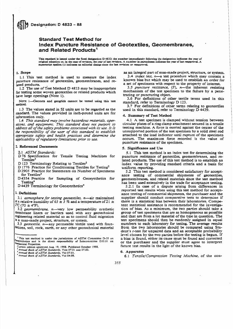
1. Scope
1.1 This test method is used to measure the indexpuncture rc&ance of geotexriles, geomembranw, and re-lated products.
1.2 The use of ~ e s t ethod D 4833 may be inappropriate
for testing some woven geotextiles or related produas which
have large openings (Note 1).
NOTE1-Gconer.s and geogrids cannot be tested using this test1 **&I-1.3 The values stated in SI units are to be regarded as the
nandard. The values provided in inch-pound units are for
information only.
1.4 This standard may involve hazardous materials, oper-
ationr. and equipment. This standard does not purport to
addressall of the safety p r o b l m associated with its use. It isthe responsibility of the user of this standard to establish
uppropriare safery and health practices and determine theapplicability of regulatory limitations prior to use.I Referenced Docum ents
2.1 ASTM Standor&D 76 Specification for Tensile Testing Machines for
Textiles2
D 123 Terminology Relating to Textiles2
D 1776 Practice for Conditioning Textiles for TestingD 2905 Practice for Statements on Number of Specimens
for Textiles3
D4354 Practice for Sampling of Geosynthetin for
Testing4D 4439 Terminology for Geosynthetics4
3.1 atmosphere for testing geotmiies, n-air maintained
at a relative humidity of 65 + 5 % and a temperature of 2 I LLTC (70 + 4 - n .3 .2 geornen;brane. n-very low permeability synthetic
membrane liners or barriers used with any geotechnical
?pineering related material so as to control fluid migntion
a man-made project, structure, or system.
3.3 geoteeiie, n-any permeable textile used with foun-
ktions, soil, rock, earth, or any other geotechnical material-Thir tc n merhod is unda the jurisdiction of ASM Cornmince D 3 5 on
r%theticr and is the dim rcspomibility of Subcornmince D35.01 on
&*ni~al ~ ~ p r e i c ry ' r dition appmved Aug. 19. 1988. Published October 1988.
Annual Book of ASTiW Standardr, Vok 07.0 and 07.02.
'Annual Book ofAST:W tandardr. VolO7.O .
* A n n u l Book of AST,U tandardf, Vof 04.08.
as an integral part of man-made project, structure, or system.
3.4 index test, n-a test procedure which may contain a
known bias but which may be used to establish an order for
a set of specimens with respect to the property of intetest.
3.5 puncture resistance, (F), n-the inherent resistingmechanism of the test specimen to the failure by a pene-
trating or puncturing objen
3.6 For definitions of other textile terms used in this
standard, refer to Terminology D 123.3.7 For definitions of other terms relating to geotextiles
used in this standard, refer to Terminology D 4439.
4. Summary of Test Method
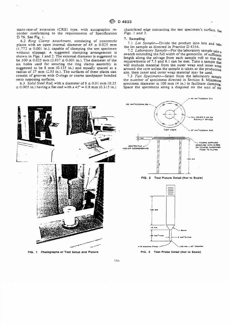
4.1 A test specimen is clamped without tension betweencircular plates of a ring clamp attachment secured in a tensiletesting machine. A force is exened against the center of the
unsupported portion of the test specimen by a solid steel rod
attached to the load indicator until rupture of the specimen
occurs. The maximum force recorded is the value of
puncture resistance of the specimen.
5. Significance and Use
5.1 This test method is an index test for determining the
puncture resistance of geotextiles, geomembranes, and re-lated products. The use of this test method is to establish anindex value by providing standard criteria and a basis for
uniform repodng.
3.2 This test method is considered satisfactory for accept-
ance testing of commercial shipments of geotextiles,
geomembranes, and related materials since the test method
has been used extensively in the trade for acceptance testing.5.2.1 In case of a dispute arising from Merences in
reported test results when using this test method for accept-
ance testing of commercial shipments, the purchaser and the
supplier should conduct comparative tests to determine if
there is a statistical bias between their laboratories. Compe-tent statistical assistance is recommended for the investiga-tion of bias. As a minimum, the two pardes should take a
group of test specimens that are as homogeneous as possible
and that are From a Iot material of the type in question. The
test specimens should then be randomly assigned in equal
numbers to each laboratory for testing. The average resultsftom the two laboratories should be compared using Stu-dent's t-test for unpaired data and an acceptable probability
Ievel chosen by the two parties before the testing is begun. If
a bias is found, either its cause must be found and corrected
or the purchaser and the supplier must agree to interpretfuture test results in the light of the known bias.
6. Apparatus6.1 TensiielCornpression Testing Machine, of the con-
7/27/2019 AStandard Test Method for Tensile Properties of Geotextiles by the Wide-Width Strip Method
http://slidepdf.com/reader/full/astandard-test-method-for-tensile-properties-of-geotextiles-by-the-wide-width 17/39
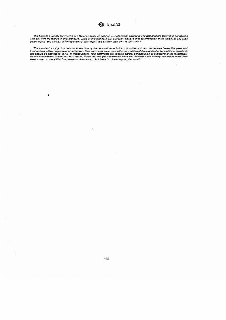
stant-rare-of extension (CRE) type. with aurogaphic re- chamfered edge conracring the test specimen's surface. sa
corde r conforming to the requirements of Spedficsrion Figs. I and 3.D 76. See Fig. I.
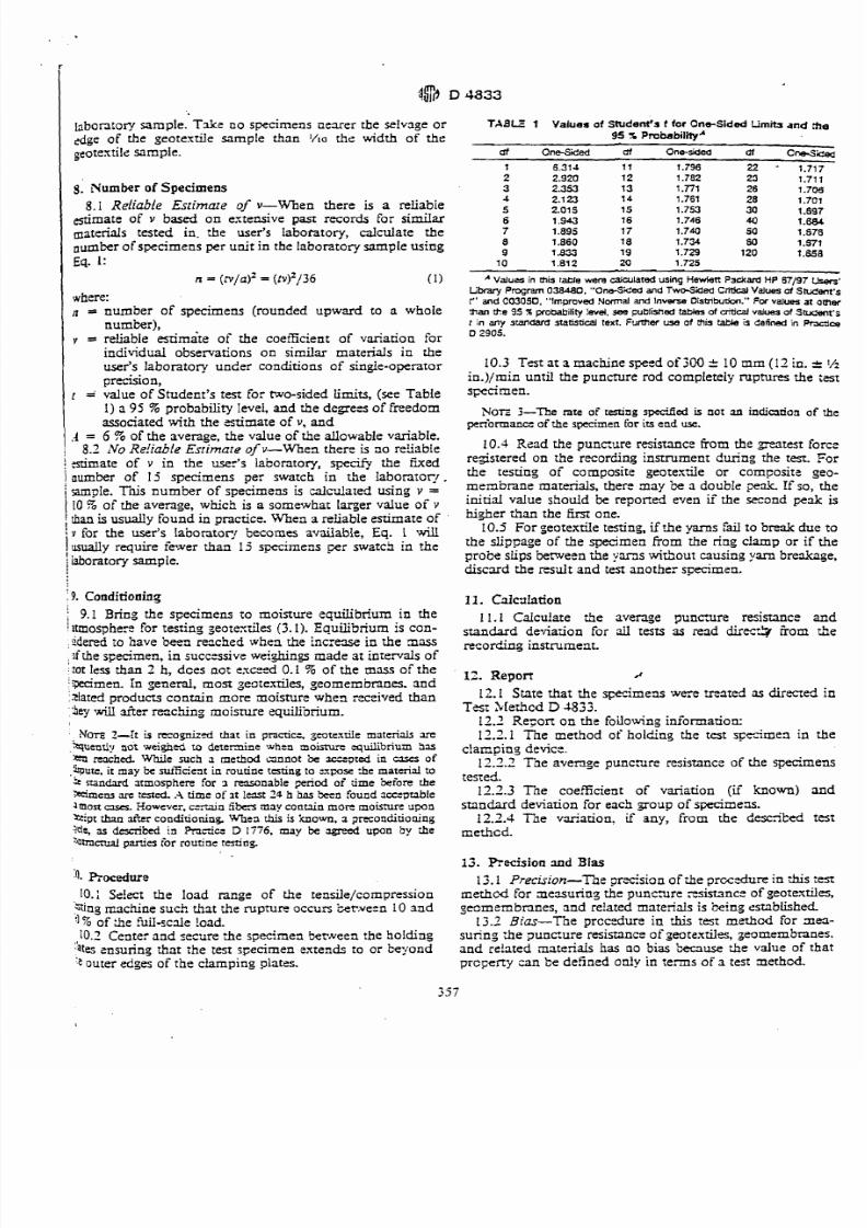
6.2 Ring Cfanlp ..irrachrtze17r, consisting of concenrricplares uith zn open internal diameter of 45 ,c 0.02:- m m
(1.772 _c 0.001 ic.). capable of clamping the test specimenuithout slippage. A suggested clamping arrangement isshown in Figs. 1 and 1.The external diam eter is suggesred tobe 100 i .025 mm (3.937 + 0.001 in.). Th e diameter of thesix holes used for securing the ring clamp assembiy iss u g e s t e d t o be 8 mm (0.135 in.) and equally spaced at aradius of 37 mm (2.95 in.). The surfaces of these plarcs canconsist of grooves with O-rings or coarse sandp aper bo ndedonto opposing surfaces.
6.3 SolidSreel Rod. with a diameter of 8 r 0.01 mm (0.350.005 in.) having 2 fiat end with 2 45" = 0.8 m m (0.5 15 in.)
>----FIG. 1 Photographs of Test Setup and Fixture
7. Sampling
7.1 Lor Sanzp/e-Divide the product inro lots and taka
the lor sample as directed in Practice D 4354.7.2 Laborarorj*Sanzple-For the laboratory sample take a
swatch extending the fuIl width of the geotextile. of sufficientlength along the selvage from each sample roll so thzt therequ irem ents of 7.3 an d 8.1 can be m et. Take a sample thatwil! exclude material from the outer wrap and inner wpar ou nd the core unless the sample is taken at th e producrionsite. then inner and outer wrap mareria! may be used.
7 .5 Tesr Specirnem-Select from the laboratory samplethe n um ber o i specimens directed in Section 8. Minimumspecimen aiamerer is 100 mm (? in.) to facilitate clampingSpace the specimens along z diagonz! on the unit of the
r 45 m r .0925mm DIC
ALL HOLES B mm D U
EOUALLY SPACED
TOP VIEW "- 7 mmf 0025mm RAD
I!
12 mm
i FAC HG SURFACES
G E C T E X T I S1'! GROOVED WITH 0-RNG
AN3JOR GEOMEMBRANEI OR COARSZ SANDPAW
FIXED TO PUTES
I50 mm
I
FIG. 2 Test Fixture Detail (Not o Scale)
-\I 6 Uachhe Fhbn OE mm . 5' Cnamlsr
FIG. 3 Test Probe Detail (Not to Scale)
7/27/2019 AStandard Test Method for Tensile Properties of Geotextiles by the Wide-Width Strip Method
http://slidepdf.com/reader/full/astandard-test-method-for-tensile-properties-of-geotextiles-by-the-wide-width 18/39
labontory sample. T&e no specimens clearer the selvage or T A B E 1 Values ot Student's t tor One-sided Limita and me
edge of the geotextile sample than 1/10 the width of the 95 % Probability*
gcotextile sample. ctt Om+Siiecl ctt One-sided df cne~;6ed
1 6.314 1 1 1.796 22 - 1717
8. Number of Specimens8.1 Reliable Estimate o v-When there is a reliable
estimate of v based on extensive past records for similarmaterials tested in. the user's labotatory, calculate thenumter of specimens per unit in the laboratory sample usingEq. 1:
n = ( r v / ~ ) ~( t y ) ' / 3 6 (1)
I where:n = number of specimens (rounded upward to a whole
num'cer),1 Y = reliable estimate of the coeEcient of variation forindividual observations on similar materials in theuser's laboratory under conditions of single-operator
precision,r = value of Student's test for two-sided limits, (see Table
1) a 95 % probability level, and the d e g e s of freedomassociated with the estimate of v, and
1 = 6 '% of the average, the vdue of the allowable variable.8.3 ~VO e!iable Estimate ofv-When there is no resable
I &mate of v in the user's laboratory, sperrfy the fixed1 oumter of 15 specimens per swatch in the Iaboratoqr .1 sample. This number of specimens is calculated using v =1 10 % of the average, which is a somewhat l ~ ~ e ralue of v
I than is usually found in practice. When a reliable estimate of! for the user's labontory becomes available, Eq. I willusually require fewer than 15 specimens per swatcj in the
f
laboratory sample.,
i 9. Conditioning
i 9.1 Bring the scecimens to moisture equilibrium in thei amosphert for testing jeotexdes (3.1). Equilibrium is con-: idered to have h n ezched when the increase in the mass;I[ the specimen, in iuccessive we ian gs made at in ten ds of;sot less than 2 h, dces not exceed 0.1 % of the mass of theiwcimen. In general, most geotexriles, geomembmes. andixlated producs contain more aoisture when received than:icy d e r re=ching moisnue eqWorium.
... ..2 2.920 12 1.782 23 1.711
3 2.353 13 1 .77l 26 1.7064 2.1 23 14 1.761 28 1.7015 2.015 15 1.753 30 1.697
6 1.943 16 1.746 40 1 . W7 1.895 17 1.740 50 1.6768 1.860 18 1.734 60 1.5719 1 a33 19 1.729 120 1.65810 1.81 2 20 1.725
A Values in this takle were calculated using Hewiett P3dard HP 67/97L'm Pmgam 038480. One-Sded and Two-Sided C M alues ot S ~ e n t ' sr ' and C03050. Improved N m a l and lnvwse Oistribodcn." For values at omw
than cte 95 % probability !evel. $eepui3isf7ed aMes of &cal values at Stucent'gt in any standara statistical texr. Further use at ais We is defined in i+ncjm0 905.
10.3 Test at a machine speed o f 3 0 ," 10 mm (11in. c 2
in.)/min until the puncture rod completely nptures the testspecimen.
NOTE -The rate of testing s ~ ~ c ds not an indiurion of thepen'ormance of the specimen for i s end m.
10.1 Read the puncure resistance from the greatest forceregistered on the recording instrument during the test. Forthe tesung of composite geotextile or comcositz gee-
membrane materials, there may be a double pa!! f so, theinitial value should be reported even if the second peak ishigher tfan the fim one.
10.3 For seotextile testing, if the yarns fail to bre& due tothe slippage of the from the ring clamp or if theprobe slips between the yarns without causing yarn breakage,
discsd the result and test another s&men.
11. Calcnlation
11.1 Caicuiate the average y unmre resismnce andstandard de-riaion for all tests ZIS iead diret7Cy &om therecording instrument.
12. Report d
12.1 State that the specimens were treated as direced inTest SIethcd D 1833.
12.2 Rezort on the foilowing information:NOTE 2-! is recognizd that in pr;lctic=, se~texriiematerials ye 12.2.1 The method of ho lz ng the test specimen in the
.%~en*i not wei&& to deternine svb=n aoisturc equilibrium h u device.'a eached While such a merhod annot be =?red in uses of 12.3.2 T"e average puncare resistance of the sp?simens,!bun.t may k mtfident in rourine testing :o expose the material to
nandvd atmosphere for 3 resonable p r i o d of time beiore the'.simens yt rested .A time of ~t lest 24 h ha k n ound ~cc=pmble 12.3.3 Tne coefficient of variation (if known) and
2 most uses. However. cenain iibers may conuin more moisture upon standard deviation for each goup of specimens.2 i p t than &r conditioning, Whezl this is :cnown. a precondirioning 12.2.3 Tse variation, if any, from the described test?dt, as descri'ced in hric D 1776, may be agreed upon by the rne*hcd-' n tmmal panies for routine testing.
13. Reci s ion md Sias
4. E O C ~ U T B 13.1 ~rec:s:on- he prxision of zhe grccxiure in *&s :est
10.: Ss!ect the load range of the rensile/compression methcd for ae sur ing the puncare resistance of geotextiles,qrng machine such that the rupture occurs kt,ve:n 10 2nd geomembranes, and related materiais is &ng established.
'1% of ;he fuiI-scde !oad. 13.2 Bias-The prccedure in this test method for xea-
10.2 Center and secure :he specimen between the holding sunng :he 2u ncure resistance of aeotextiles, geomembranes.
ates cnsurinq that the test specimen extends to or beyond and re!ated rnateriais has ao bias h a u s e the value of that'e outer edges of the clamping plates. prcceny cank efined only in :e n s of a test aethcd.
7/27/2019 AStandard Test Method for Tensile Properties of Geotextiles by the Wide-Width Strip Method
http://slidepdf.com/reader/full/astandard-test-method-for-tensile-properties-of-geotextiles-by-the-wide-width 19/39
The American Sociery for Tesrmg and Marerials rakes no pasrtion respecting the validiry of any parenr righrs asseffed in connection
wirh any item menrioned in rhis standard. Users o! rhis srandard are expressly advised that dererminarion of rhe validiry of any sucn
perenr rights, and the risk of infringemenr of such righrs, are entireiy their own responsibility.
Thrs standard is subjecr to revrsion at any time by rhe responsible rechnical committee and musr be reviewed every five years andif nor revised, either rea pp ro vd or wrfhdrawn. Your commenrs are invned either for revis ion of this srandard or for eddirional srandards
and should be addressed to ASTM Ht38dqUan~~S.our comments will receive careful consideration at a meeting of the responsible
rechnical committee, which you may attend. If you feel thar your commenrs have nor received a lair hearing you should make your
views known t~ the ASTM Cornmitree on Srandards. 1916 Race St.. Philadelph8. PA 19103.
7/27/2019 AStandard Test Method for Tensile Properties of Geotextiles by the Wide-Width Strip Method
http://slidepdf.com/reader/full/astandard-test-method-for-tensile-properties-of-geotextiles-by-the-wide-width 20/39
Designation: D 5084 - 90dmStandard Test Method for
Measurement of Hydraulic Conductivity of Saturated PorousMaterials Using a Flexible Wall ~ermeameter'
This standard is isrued under the rued designation D 5081; rhe number immediately fouomng the designation indicata the y u r of
original adoption or. in rhecyc of d s i o n , the year of last revision. A number in paentheses ind ium the yearof lact reapproval.Asupmrript epsilon (e) indiaus m editorialchange since the last revirion or mpprovd.
1. Scope
1.1 This test method covers laboratory measurement ofthe hydraulic conductivity (also referred to as coeflcienr of
permeability) of water-saturated porous materials with aflexible wall permeameter.
1.2 This test method may be utilized with undisturbed o r
compacted specimens that hav e a hydrau lic co nductivity lessthan or equal to 1 x lo-' m/s (1 x 10⁻³ cm/s).'
1.3 The hydraulic conductivity of materials with hy-draulic conductivities grea ter tha n 1 x m/s may be
determined by Test Method D 2434.1.4 The values stated in SI units are to be regarded as the
standard, unless other units are specifically given. By tradi-tion in U.S. practice, hydraulic conductivity is reporced incentimetres per second, althou gh th e com mo n SI units forhydraulic conductivity are metres per second.
1.5 This standard does nor prc~on o address the safety
problem associated with its use. It is the responsibility of the
user of this standard to establish appropriare safety and
health practices and determine the applicability of regulatory
limitations prior to use.
2. Referenced Documents
2.1 ASZW Standards: 'D 653 Terminology Relating t o Soil, Rock, and ContainedRuidsZ
D 698 Test Methods for Moisture-Density Relations ofSoils and Soil-Aggregate Mixtures Using 5.5-lb (2.49-kg)Rammer and 12-in. (305-mm) Drop2
D 1557 Test Methods for Moisrure-Density Relations ofSoils and Soil-Aggregate Mixtures Using 10-lb (4.54-kg)Rammer and 18-in. (457-mm) Drop'
D 587 Practice of Thin-W alled T ub e Sam pling of Soils'D2113 Practice for Diamond Core Drilling for Site
InvestigationZD 21 6 Method for Laboratory Determ ination of Water
(Moisture) Content in Soil, Rock, and SoilLAggregateMixtures=
D2434 Test Method for Permeability of Granular Soils(Constant Head)l .
D4220 Practices for Preserving and Transporting SoilSamplesz-
This test mahod is under the juridiction of A S M Cornminee D-18 on Soil
ad Rock and is the d i m responsibility of Subcommina D 18.04 on Hydrologic
b~eniaf Soil and Roch.Cumnr edition approved June 29. 1990. Published Ocrober 1990.
'Ann& Book of AST,M Standards, VolW.08.
D 4753 Specifica tion for Evaluating, Selecting and Speci-fying Balances and Scales for Use in Soil and RockTesting2
D 4767 Test Method for Consolidated-Undrained TriaxialCompression"
E 145 Specification for Gravity-Convection and Forced-Ventilation Ovens3
3. Terminology
3.1 Definitions:
3.1.1 hydraulic conductivity, k-the rate of disch arge ofwater under laminar flow conditions through a unit cross-sectional area of a porous medium under a unit hydraulicgradient a nd standard temperature conditions (20'C).
DI~~USSION-fheerm coeflcient of penneabiiity is ofien used
instead o f .hydraulic conductivity, but hydraulic condwtivity k used
exclusively in this test method. A more complete discussion of the
terminology associated with Darcy's law is given in the l iterat~re.~
3.1.2 pore volumeofflow-the cumulative quantity offlowinto a test specimen divided by the volume of voids in thespecimen.
3.1.3 For definitions ofot her terms used in this test metho d,see Terminology D 653.
4. Significance and Use
4.1 This test method applies to one-dimensional, lamina rflow of water within porous materials such as soil and rock
4.2 Th e hydraulic conductiv ity of porous materials gener-ally decreases with an increasing amount of air in the poresof the material. Th is test m ethod applies to water-sanuatedporous materials containing virtually no air.
4.3 This test method applies to permeation of porousm ate rid s with water. Penneatio n with other liquids, such as
chemical wastes, can be accomplished using proceduressimilar to those described in this test method. However, thistest method is only intended to be used when water is thepenneant Liquid.
4.4 It is assumed that Darcy's law is valid and that thehydrau lic cond uctivity is essentially unaffected by hyd raulicgradient. The validity of Darcy's law may be evaluated bymeasuring the hydraulic conductivity of the specimen atthree hydraulic gradients; if all measured values are similar(within about 35 %), then Darcy's law may be taken as valid.However, when the hydraulic gradient acting on a test
8
' nnual Book o ASTM Standardr. Vol04.02.
Olson. R. E., and Daaie1. D. E.. ".We~uremcnt f the Hyhul ic Conduaivityof FineCraincd Soils," Symposium on Permeability and Groundwater Contami-
nant Transport. .JSTtKSTP 746.ASTM, I98I.pp. 18-64.
7/27/2019 AStandard Test Method for Tensile Properties of Geotextiles by the Wide-Width Strip Method
http://slidepdf.com/reader/full/astandard-test-method-for-tensile-properties-of-geotextiles-by-the-wide-width 21/39
specimen is changed, the state of stress will also change, and,
if the specimen is compressible, the volume of the specimen
will change. Thus, some change in hydraulic conductivitymay occur when the hydraulic gradient is altered, even in
cases where Darcy's law is valid.4.5 This test method provides a means for determining
hydraulic conductivity at a controlled level of effective stress.Hydraulic conductivity varies with varying void ratio, which
in turn changes when the effective stress changes. If the void
ratio is changed, the hydraulic conductivity of the test
specimen will likely change. To determine the relationship
between hydraulic conductivity and void ratio, the hydraulic
conductivity test would have to be repeated at different
effective stresses.4.6 The correlation between results obtained with this test
method and the hydraulic conductivities of in-place field
materials has not been fully investigated. Experience hassometimes shown that flow panerns in small test specimens
do not necessarily follow the same panerns on large fieldscales and that hydraulic conductivities measured on small
test specimens are not necessarily the same as larger-scale
values. Therefore, the results should be applied to field
situations with caution and by qualified personnel.
5. Apparatus
5.1 Hydraulic System-Constant head (Method .4),falling head (Methods B and C), or constant rate of flow .(Method D) systems may be utilized provided they meet the
criteria outlined as follows:
5.1.1 Consfant Head-The system must be capable of
maintaining constant hydraulic pressures to within 2 5 %
and shall include means to measure the hydraulic pressuresto within the prescribed tolerance. In addition, the head loss
across the test specimen must be held constant to within
c 5 % and shall be measured with the same accuracy or better.
Pressures shall be measured by a pressure gage, electronic
pressure transducer, or any other device of suitable accuracy.
5.1.2 Falling He&-The system shall allow for measure-
ment of the applied head loss, thus hydraulic gradient, towithin 5 % or better at any time. In addition, the ratio of
initial head loss divided by final head loss over an interval of
time shall be measured such that this computed ratio isaccurate to within k 5 %. The head loss shall be measuredwith a pressure gage, electronic pressure transducer, engi-
neer's scale, graduated pipette, or any other device of suitable
accuracy. Falling head tests may be performed with either aconstant tailwater elevation (Method B) or a rising tailwater
elevation (Method C).
5.1.3 Constant R a e o Flow-The system must be ca-pable of maintaining a constant rate of flow through the
specimen to within 5 % or better. Row measurement shall
be by calibrated syringe, graduated pipette, or other device of
suitable accuracy. The head loss across the specimen shall be
measured to an accuracy of 5 % or better using an electronic
pressure transducer or other device of suitable accuracy.More information on testing with a constant rate of flow isgiven in the literature.'
'Olson, H. W Morin, R. H., and Nichols. R. W., "Flow Pump Applicalions inTriaxial Testing." S.vmposium on Advanced Triaxial Tesring qf Soil and Rock.ASTM STP 977. ASTM. 1988. pp. 68-8 1.
5.1.4 System De-airing-The hydraulic system s h adesigned to facilitate rapid and complete removal of free
bubbles from flow lines;5.1.5 Back Pressure System-The hydraulic system s ha
have the capability to apply back pressure to the specimen ofacilitate saturation. The system shall be capable of main.taining the applied back pressure throughout the duration of
hydraulic conductivity measurements. The back pressuR
system shall be capable of applying, controlling, and me&
suring the back pressure to 5 % or. bener of the applied
pressure. The back pressure may be provided by a corn.
pressed gas supply, a deadweight acting on a piston, or myother method capable of applying and controlling the back
pressure to the tolerance prescribed in this paragraph.
NOTE I-Application of gas pressure directly to a fluid will d h l v cgas in the fluid. A variery of techniques are available to minimizedissolution o f gas in the back pressure fluid. including separation ofaand liquid phases with a bladder and frcquenr replacement of the liquid
with de-aired water.
5.2 Flow Measurement System-Both inflow and outflow
volumes shall be measured unless the lack of leakagt,
continuity of flow, and cessation of consolidation or swelling
can be verified by other means. Row volumes shall be
measured by a graduated accumulator, graduated pipette,
vertical standpipe in conjunction with an electronic pressure
transducer, or other volume-measuring device of suitable
accuracy.
5.2.1 Flow Accuracy--Required accuracy for the quantity
of flow measured over an interval of time is 5 '3% or better.
5.2.2 De-airing and Compliance of the S~mem-The flow-
measurement system shall contain a minimum of dead space
and be capable of complete and rapid de-airing. Complianceof the system in response to changes in pressure shall beminimized by using a stiff flow measurement system. Rigidtubing, such as metallic or rigid thermoplastic tubing, shallbe used.
5.2.3 Head Losses-Head losses in the tubes, valves,
porous end pieces, and mter paper may lead to error. TOguard against such errors, the permeameter shall be assem-bled with no specimen inside and then the hydraulic sy-
fiiled. If a constant or falling head test is to be used, the
hydraulic pressures or heads that will be used in testing a
specimen shall be applied, and the rate of flow measured
with an accuracy of 5 % or bener. This rate of flow shallbe at
least ten times greater than the rate of flow that is measured
when a specimen is placed inside the permearneter and the
same hydraulic pressures or heads are applied. If a c o n m t -.
rate of flow test is to be used, the rate of flow to be used in ,
testing a specimen shall be supplied to the permeameter andthe head loss measured. The head loss without a specimen ,.
shall be less than 0.1 times the head loss when a specimen3.'
present.
5.3 Permeameter Cell Pressure System-The system for
pressurizing the pe-rmeameter cell shall be capable of aP* :
plying and controlling the cell pressure to within 5 % of fb e
applied pressure. However, the effective stress on the tea
specimen (which is the difference between the cell prewand the pore water pressure) shall be maintained to
desired value with an accuracy of 10 % or bener. The devisfor pressurizing the cell may consist of a reservoir tonne?to the permeameter cell and partially filled with de-arcd
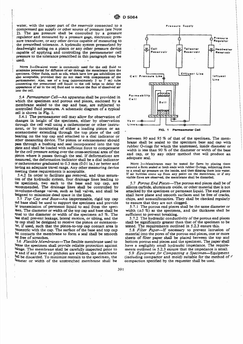
7/27/2019 AStandard Test Method for Tensile Properties of Geotextiles by the Wide-Width Strip Method
http://slidepdf.com/reader/full/astandard-test-method-for-tensile-properties-of-geotextiles-by-the-wide-width 22/39
water, with the upper part of the reservoir connected to acompressed gas supply or other source of pressure (see Note
1 2). The gas pressure shall be controlled by a pressure! regulator and measured by a pressure gage, electronic pres-
i sure transducer, or any other device capable of measuring tothe prescribed tolerance. A hydraulic system pressurized byi deadweight acting on a piston or any other pressure device
i capable of applying and.controlling the permeameter cellp ~ s s u t eo the tolerance prescribed in this paragraph may be
i
/ NOTE 2-De-aid water is commonly used for the cell fluid toI minimize potential for d i f i o n of air through the membrane into the
specimen. Other fluids, such as o h which have low gas soiubiliria arcalso acceptable, provided they do nor react with components of thepermeametcr. A h , use of a long (approximately 5 to 7 m) tubeconnecting the pressurized cell liquid to the cell heips to &lay theappearance of air in the a! fluid and to ruluce the flux of dissolved airinto the ell.
5.4 Pememerer Cell-An apparatus shallbe provided in
which the specimen and porous end pieces, enclosed by a
membrane sealed to the cap and base, are subjected tocontrolled fluid pressures. A schematic diagram of a typical
cell is shown in Fig. 1.
5.4.1 The permeameter cell may allow for observation of
changes in height of the specimen, either by observation
tbrough the cell wall using a cathetometer or other instru-ment, or by monitoring of either a loading piston or anextensometer extending through the top plate of the ceil
bearing on the top c ap and anached to-a dial indicator orother measuring device. The piston or extensometer should
pass through a bushing and seaI incorporated into the topplate and shall be loaded with sdficient force to compensate
for the cell pressure acting over the cross-sectional area of thepiston where it passes through the seal. If deformations are
measured, the deformation indicator shall be a dial indicator
or cathetometer graduated to 0.3 mm (0.01 in.) or better andhaving an adequate travel range. Any other measuring device
meeting these requirements is acceptable.
5.4.2 In order to facilitate gas removal, and thus satura-tion of the hydraulic system, four drainage lines leading to
the specimen, two each to the base and top cap, are
Ecommended The drainage lines shall be controlled byvolume-change valves, such as ball valves, and shall be
'kigned to minimize dead space in the lines.
5.5 Top Cap and Base-An impermeable, rigid top cap
lad base shall be used to support the specimen and provide:or transmission of pennant liquid to and from the spec-
ken. The diameter or width of the top cap and base shall begual to the diameter or width of the specimen 25 %. Theke shall prevent leakage, lateral motion, or tiIting, and the
pp cap shall be designed to receive the piston or extensom-.Yr, if used, such that the piston-to-top cap contact area isPncenmc with the cap. The surface of the base and top cap
hat contacts the membrane to form a seal shall be smoothQd free of scratches.
5.6 Flexible Membranes-The flexible membrane used to
?case the specimen shall provide reliable protection againste g e . The membrane shall be carefully inspected prior to* and if any flaws or pinholes are evident, the membrane
bll be discarded. To minimize restrain to the specimen, the
&meter or width of the unstretched membrane shall be
P r e 9 s u r a S u p p l y
I
Tallwatrr
R s r r r v o l r
1 1 ~ f f ~ u j ~ ~ ~l n r Ie l l P r r r s u r r L ln r l n f l u s n t
L ine
P e r m e a b l l l t y
C e l l
Ve n t
L I n s - 1
FIG. 1 PermeameterCell
between 90 and 95 % of that of the specimen. The mem-
brane shall be sealed to the specimen base and cap withrubber O-rings or which the unstressed, inside diameter or
width is less than 90 % of the diameter or width of the baseand cap, or by any other method that will produce an
adequate seal.
NOTE3-Membranes may be tested for flaws by placing themaround a form sealed at both ends with rubber O-rings, subjecting themto a small air pressure on the inside, and then dipping them into water.If air bubbles come up from any point on the membrane, or if anyvisible flaws arc observed. the membrane shall be discarded.
5.7 Porous End Pieces-The porous end pieces shall be ofsilicon carbide, aluminum oxide, or other materia1 that is not
attacked by the specimen or penneant liquid. The end pieces
shall have plane and smooth surfaces and be free of cracks,
chips, and nonunifonnities. They shall be checked regularlyto ensure that they are not clogged.
5.7.1 73e porous end pieces shall be the same diameter or
width (25 %) as the specimen, and the thickness shall besufficient to prevent breaking.
5.7.2 The hydraulic conductivity of the porous end pieces
shall be significantly greater than that of the specimen to betested. The requirements outlined in 5.2.3 ensure this.
5.8 Filter Paper-If necessary to prevent intrusion ofmaterial into the pores of the porous end pieces, one or moresheets of filter paper shall be placed between the top andbottom porous end pieces and the specimen. The paper shallhave a negligibly small hydraulic impedance. The require-
menu outlined in 5.2.3 ensure that the impedance is small.5.9 Equipment for Compacting a Specimen-Equipment
(including compactor and mold) suitable for the method ofcompaction specified by the requester shall be used.
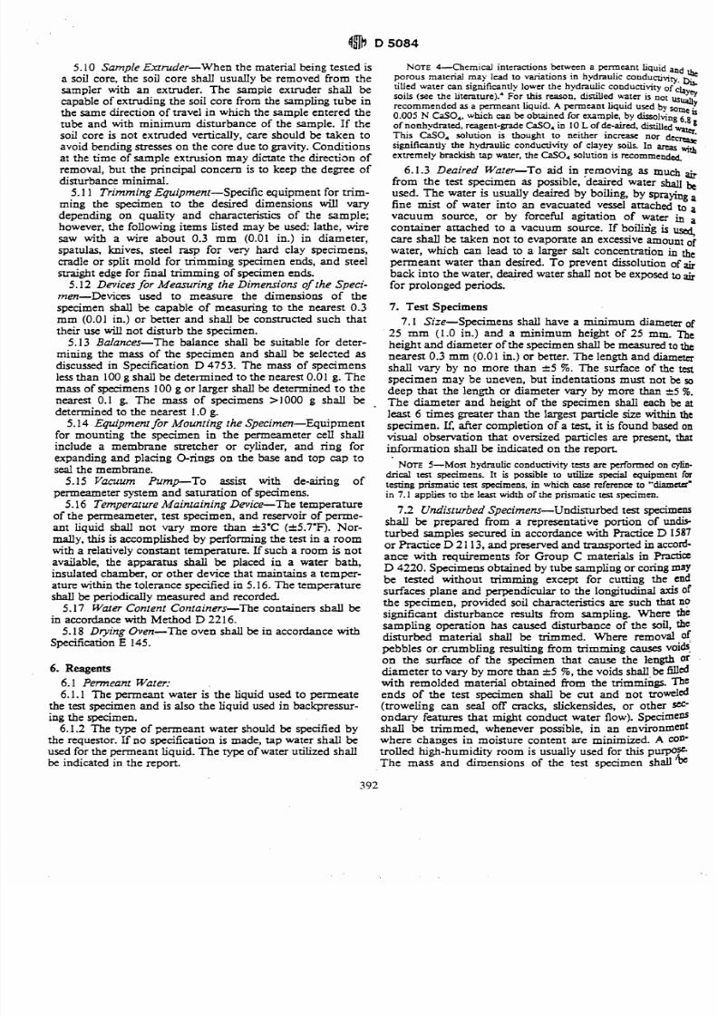
7/27/2019 AStandard Test Method for Tensile Properties of Geotextiles by the Wide-Width Strip Method
http://slidepdf.com/reader/full/astandard-test-method-for-tensile-properties-of-geotextiles-by-the-wide-width 23/39
5.10 Sample Extruder-When the material being tested isa soil core, the soil core shall usually be removed from thesampler with an extruder. The sample extruder shall becapable of extruding the soil core from the sampling tube inthe same direction of travel in which the sample entered thetube and with minimum disturbance of the sample. If thesoil core is not extruded vertically, care should be taken toavoid bending stresses on the core due to gravity. Conditions
at the time of sample extrusion may dictate the direction ofremoval, but the principal concern is to keep the degree ofdisturbance minimal.
5.1 1 Trimming Equipment-Specific equipment for trim-
ming the specimen to the desired dimensions will varydepending on quality and characteristics of the sample;however, the following items listed may be used: lathe, wiresaw with a wire about 0.3 mm (0.01 in.) in diameter,spatulas, knives, steel rasp for very hard clay specimens,cradle or split mold for trimming specimen ends, and see1straight edge for final trimming of specimen ends.
5.12 Devices for Measuring the Dimensions o the Speci-men-Devices used to measure the dimensions of the
specimen shall be capable of measuring to the nearest 0.3mm (0.01 in.) or better and shall be constructed such thattheir use will not disturb the specimen.
5.13 Balances-The balance shall be suitable for deter-mining the mass of the specimen and shall be selected asdiscussed in Specification D 4753. The mass of specimensless than 100 g shall be determined to the nearest 0.01 g. The
mass of specimens 100 g or larger shall be determined to thenearest 0.1 g. The mass of specimens > I 000 g shall be
determined to the nearest 1.0 g.5.1 4 Equipment for Mounting he Specimen-Equipment
for mounting the specimen in the permeameter cell shallinclude a membrane stretcher or cylinder, and ring forexpanding a d lacing O-rings on the base and top cap to
seal the membrane.5.15 Vacuum Pu mp-To assist with de-airing of
permeameter System and saturation of specimens.5.16 Temperature Maintaining Device-The temperature
of the permeameter, test specimen, and reservoir of perme-ant liquid shall not vary more than f3'C (k5.7'F). Nor-mally, this is accomplished by performing the test in a roomwith a relatively constant temperature. If such a room is notavailable, the apparatus shall be placed in a water bath,
insulated chamber, or other device that maintains a temper-ature within the tolerance specified in 5.16. The temperatureshall be periodically measured and recorded.
5.17 Water Conlent Containers-The containers shall be
in accordance with Method D 22 16.5.18 Drying Oven-The oven shall be in accordance withSpecification E 145.
6. Reagents
6.1 Penneant Water:6.1.1 The permeant water is the liquid used to permeate
the test specimen and is also the liquid used in backpressur-ing the specimen.
6.1.2 The type of permeant water should.be specified bythe requestor. If no specification is made, tap water shall beused for the permeant liquid. The type of water utilized shallbe indicated in the report.
NOTE -Chemical interact ions betwe en a permeant liquid andporous material may lead to variations in hydraulic mnductjvit)..Dit,tilled water can significantly lower the hydraulic conductivity of
QY,,soils (see the liter a~u re).~or this reason, distilled water is notrecommended as a permean t liquid. A permea nt liquid used by some0.005 N CaSO,, which can be obrained for exampie, by dissolving 6.8
of nonhydrated, reagent-gradeCaSO, in 10L f de-aired, dinillcd WathWathThis CaS04 soluuon is thought to neither incrwe nor d
=cm?csignificantly the hydraulic conductivity of clayey soils. In arm with
extremely brackish rap water, the C&O4 soluuon is ItCOmrnendd
6.1.3 Deaired Water-To aid in removing as much ai,
from the test specimen as possible, deaired water shall kused. The water is usually deaired by boiling, by sprayingafine mist of water into an evacuated vessel attached to avacuum source, or by forceful agitation of water in acontainer attached to a vacuum source. If boilixig is use4care shall be taken not to evaporate an excessive amount of
water, which can lead to a larger salt concentration in thepermeant water than desired. To prevent dissolution of a~
back into the water, deaired wzter shall not be exposed to&
for prolonged periods.
7. Test Specimens7.1 Size-Specimens shall have a minimum diameter of
25 mm (1.0 in.) and a minimum height of 25 mm. Theheight and diameter of the specimen shall be measured to t&
nearest 0.3 mm (0.01 in.) or better. The length and diametershall vary by no more than &5 %. The surface of the test
specimen may be uneven, but indentations must not be sodeep that the length or diameter vary by more than a5 %.
The diameter and height of the specimen shall each be at
least 6 times greater than the largest particle size within thespecimen. If, after completion of a test, it is found based onvisual observation that oversized panicles are presen4 that
information shall be indicated on the repon
NOTE 5- M os hydraulic conductivity ttsts are performed on cylin-drical test specimens. It is possible to utiike special equipment fortesting prismatic t m specimens, in which case refercna to "diameter"in 7.1 a u ~ l i ao the least width of the ~rismaucest succimen.-
7.2 Undisturbed Specimens-Undisturbed test specimensshall be prepared from a representative portion of undis-turbed samples secured in accordance with Practice D 1587or Practice D 2 1 13, and preserved and transported in accord-ance with requirements for Group C materials in PmctieD 4220. Specimens obtained by tube sampling or coringmaybe tested without trimming except for cutting the endsurfaces plane and perpendicular to the longitudinal axis ofthe specimen, provided soil characteristics are such that nosignificant disturbance results from sampling. Where the
sampling operation has caused disturbance of the soil, thedisturbed material shall be trimmed. Where removal ofpebbles or. crumbling resulting from mmming causes voidson the surface of the specimen that cause the length ordiameter to vary by more than A5 %, the voids shall,be filledwith remolded material obtained from the uimmings. ?beends of the test specimen shall be cut and not troweled(troweling can seal off cracks, slickensides, or other set*
ondary features that might conduct water flow). Specimensshall be trimmed, whenever possible, in an environmentwhere changes in moisture content are minimized. A con-trolled high-humidity room is usually used for this purpose.The mass and dimensions of the test specimen shall$
7/27/2019 AStandard Test Method for Tensile Properties of Geotextiles by the Wide-Width Strip Method
http://slidepdf.com/reader/full/astandard-test-method-for-tensile-properties-of-geotextiles-by-the-wide-width 24/39
determined to the tolerances given in 5 . 1 2 and 5 . 1 3 . The testspecimen shall be mounted immediately in the permeam-eter. The water content of the trimmings shall be determinedin accordance with Method D 2216.7.3 LuborarotyCompacted Specimens-The material to
be tested shall be prepared and compacted inside a mold in amanner specified by the requestor. If the specimen is placedand compacted in layers, the surface of each previously-
compacted layer shall be lightly scarified (roughened) with afork, ice pick, or other suitable object, unless the requesterspecifically states that scarification is not to 'be performed.Test Methods D 698 and D 1557 describe two methods ofcompaction, but any other method specified by the requestormay be used as long as the method is described in the report.Large clods of material should not be broken down prior tocompaction unless it is known that they will be broken infieId construction, as well, or the requestor specificallyrequests that the clod sizebe reduced. Neither hard clods norindividual particles of the material shall exceed '/s of eitherthe height or diameter of the specimen. Afier compaction,the test specimen shall be removed from the mold, the endsscarified, and the dimensions and weight determined within
the tolerances given in 5.12 and 5.13. After the dimensionsand mass a& determined, the test specimen shall be imme-diately mounted in the permeameter. 'The water content ofthe trimmings shall be determined in accordance withMethod D 22 16.7.4 Other Preparation Metho&-Other methods of p rep
aration of a test specimen are permitted if specificallyrequested. The method of specimen preparation shall be
identified in the reporr.7.5 After the heighf diameter, mass, and water content of
the test specimen have been determined, the dry unit weightshall be calcuiated AIso, the initial degree of saturation shallbe estimated (this nformation may be used later in the
backpressure stage).
8. Procedure
8.1 Specimen Setup:8.1.1 Cut two filter paper sheets to approximately the
same shape as the cross section of the test specimen. Soak thehvg porous end pieces and filter paper sheets, if used, in acontainer of permeant water.
8.1.2 Place the membrane on the membrane expander.Apply a thin coat of silicon high-vacuum grease to the sidesofthe end caps. Place one porous end piece on the base and?lace one filterpaper sheet, if used, on the porous end piece,followed by the test specimen. Place the second filter papersheet,
if used, on top of the specimen followed by the secondWrous end piece and the top cap. Place the membranewound the specimen,agd using the membrane expander orother suitable O-ring expander, place one or more O-rings toseal the membrane to the base and one or more additionalbrings to seal the membrane to the top cap.
8.1.3 Attach flow tubing to the top cap, if not alreadyWched, assemble the permeameter cell, and fill it withde-aired water or other cell fluid. Attach the ceil pressureQmoir to the permeameter cell line and the hydraulicSnem to the influent and emuent lines. Fill the cell pressure'weir with deaired water, or other suitable liquid, and thehydraulic system with deaired permeant water. Apply a small
Required Backpressure (psi)
FIG. 2 Back Pressureto Attain Various Degrees of Saturations
confining pressure of 7 to 35 kPa (1 to 5 psi) to the cell andapply a pressure less than the confining pressure to both theinfluent and effluent systems, and flush permeant waterthrough the flow system. After all visible air has beenremoved from the flow lines, close the control valves. At notime during saturation of the system and specimen orhydraulic conductivity measurements shall the maximumapplied effective stress be allowed to exceed that to which thespecimen is to be consolidated.
8.2 Specimen Soaking (Optional)-To aid in saturation,specimens may be soaked under partial vacuum applied tothe top of the specimen. Atmospheric pressure shall beapplied to the specimen base through the influent lines, and
the magnitude of the vacuum set to generate a hydraulicgradient across the sample less than that which will be usedduring hydraulic conductivity measurements.
NOTE -Soaking under vacuum is applicable when t h m are
continuous air voids in the specimen. Soaking under vacuum is onlyrecommended for ten specimens with initial deg ms of saturation below70 %. The specimen may swell when exposed to water: the effectivestress will tend to counteraa the swelling. However. for materials thattend to swell. unless the applied effm ive mess is greaterthan or qua1 tothe swell pressure, the specimen will MU.
8.3 Backpressure Saturation-To saturate the specimen,backpressuring is usually necessary. Figure 2 provide guid-ance on back pressure required to attain saturation.
NO= 7-Figure 2 assume s that th e water used for back pressure isdeaired and that the only source for air to dissolve into the water is airfrom the tcst specimen. If air pressure is used to control the backpressure. pressurized air will dissolve into the water. thus reducing thecapacity of the water used for back pressure to dissolve air located in thepores of the tcst specimen. The problem is minimized by using a long(>5 m) tube that is impermeable to air between the air-water interfaceand test spec ime n, by separating the back-pressure water from the air bya material or fluid that is relatively impermeable to air, by periodicaliyreplacing the back-pressure waterwith deaircd water, or by o ther means.
Lowe. J.. and Johnson. T. C.,"Use of Back b u r r o 1 Degree ofSaturation of Triaxial Tar Specimens,"Proceedings. ASCE Research Confuenceon Shear Strength o j Cohesive Soils, Boulder. CO . 1960. r'
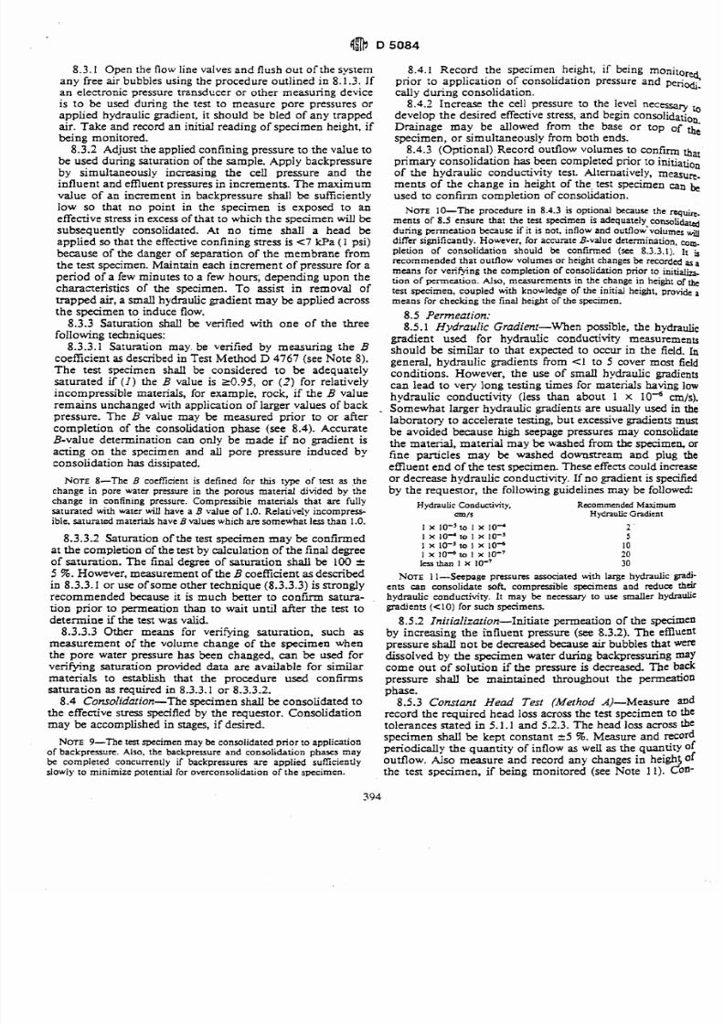
7/27/2019 AStandard Test Method for Tensile Properties of Geotextiles by the Wide-Width Strip Method
http://slidepdf.com/reader/full/astandard-test-method-for-tensile-properties-of-geotextiles-by-the-wide-width 25/39
8.3.1 Open the flow line valves and flush o ut of the systemany free air bubbles using the procedure outlined in 8.1.3. Ifan electronic pressure transducer o r othe r measuring deviceis to be used during the test to measure pare pressures orapplied hydraulic gradient, it should be bled of any trappedair. Ta ke and record a n initial reading of spe cimen height, ifk i n g monitored .
8.3.2 Adjust the applied confining pressure to the value tobe used during saturation of the sample. Apply backpressureby simultaneously increasing the cell pressure and theinfluent and em uent pressures in increments. Th e m aximumvalue of an increment in backpressure shall be suficientlylow so that no point in the specimen is exposed to aneffective stress in excess of that to which t he specime n will be
subsequently consolidated. At no time shall a head beapplied so that the effective confining stress is t 7 Pa ( 1 psi)because of the danger of separation of the membrane fromthe test sm cimen. M aintain each increm ent of Dressure for aperiod o i a few minutes to a few hou n; d ep en2 ng upon thecharacteristics of the specimen. To assist in removal oftrapped air, a small hydraulic gradient may be applied across
the specimen to induce flow.8.3.3 Saturation shall be verified with one of the three
following techniques:8.3.3.1 Saturation may. be verified by me asur ing the B
coefficient as described in Test Method D 4767 (see Note 8).The test specimen shall be considered to be adequatelysaturated if ( I ) he B value is 20.95, or ( 2 ) or relativelyincompressible materials, for example, rock, if the B valueremains unchanged with application of larger values of backpressure. The B value may be measured prior to or aftercompletion of the consolidation phase (see 8.4). AccurateB-value determination can onlv be made if n o m d i e n t isacting on the specimen and pore pressure induced byconsolidation has dissipated.
NOTE8-The B coefficient is defined for this type of test as j echange in pore water pressure in the porous material divided by thechange in confining pressure. Compressible materials that are fullysaturated with water will have a B value of 1.0. Relatively incompress-ible, saturated materials haveB values which are somewhat less than 1.0.
8.3.3.2 Saturation of the test specime n m ay be confirmed
at the comp letion of the test by calculation of the final degreeof saturation. T he final degree of saturation shall be 100 r5 5%. However, measurement of the B coefficient as describedin 8.3.3. I or use of some oth er techniq ue (8.3.3.3) is stronglyrecommended because it is much bet te r t o c o n f m sa tura-tion prior to permeation than to wait until after the test todetermine if the test was valid.
8.3.3.3 Other means for verif yng s atura tion, such asmeasurement of the volume change of the specimen whenthe pore water pressure has been changed, can be used forverifying saturation provided data are available for similarmaterials to establish that the procedure used confirmssaturation as required in 8.3.3. I o r 8.3.3.2.
8.4 Consolidation-The specimen shall be consolidated t othe effective stress specified by the requestor. Consolidationmay be accom plished in stages, if desired.
8.4.1 Record the specimen height, if being moniro'eqprior to application of consolidation pressure and periodi-
cally d uring consolidation.8.4.2 Inc rease the cell pressure to the level necessary to
develop the desi red effect ive stress, and begin C O n ~ ~ l i d ~ t iDrainage may be allowed from the base or top of thespecime n, or simultaneously from both ends.
8.4.3 (Optional) Record outflow volumes to confirm thatprimary consolidation has been completed prior to initiationof the hydraulic conductivity test. Alternatively, measure-me nts o f the change in height of the, test specimen canused to confirm completion of consolidation.
XOTE 10-The procedure in 8.4.3 is optional because the rq*.ments of 8.5 ensure that the test specimen is adequateIy,c~n.wli&~during permeation because if it is not, inflow and outflow volumesadiffer significantly. However , for accurate B-value determination, corn.
pletion of consolidation should be confinned (see 8.3.3.1). 11 trecommended that outflow volumes or height changes be recorded asa
means for verifying the completion of consolidation prior to i n i t i htion of penn eation . N s o , measurements in the change in height of the
test specimen, coupled with knowledge of the initial height, provide a
mea ns for checking the final height of the specimen.
8.5 Permeation:8.5.1 Hyd ra ul ic Gradient-When possible, the hydraulic
gradient used for hydraulic conductivity measurementsshould be similar to that expected to occur in the field. Ingeneral, hydraulic gradients from (1 to 5 cover most fieldconditions. How ever, th e use of small hydraulic gradientscan lead to very long testing times for materials having lowhydraulic conductivity (less than about 1 x 10 '~ cm/s).Somewhat larger hydraulic gradients are usually used in thelaboratory to accelerate testing, but excessive p a d e n ts mustbe avoided because high seepage pressures may consolidatethe material, material may be washed from the specimen, orfine particles may be washed downstream and plug the
eff lue nt en d o f the test specimen. T hese effects could increaseor decreas e hy drau lic conductivity. If no gradient is specifiedby th e re que stor, the following guidelines may be followed:
Hydraulic Conductivity, Recommended Maximumc m / S Hydraulic Gradient
NOTE 1 1-Seepage pressures associated with large hydraulic@-
ents can consolidate soft comprasible spbcimens and redua thar
hydraulic conductivity. It may be nKessary to use smaller hydraulicgradients ( 4 0 ) or such specimens.
8.5.2 Initialization-Initiate perm eation of the specimenby increasing the influent pressure (see 8.3.2). The emuentpressure shall not be decreased because air bubbles that weredissolved by the specimen water during backpressuring maycome ou t of solution if the pressure is decreased, Th e backpressure shall be maintained throughout the permeationphase.
8.5.3 Constant Head Test (Method A)-Measure andrecord the required head loss across the test specimen to thetolera nces stat ed in 5.1.1 an d 5.2.3. Th e head loss across the
NOTE 9-The test specimen may be consolidated prior to applicationspecimen shall be kept constant k 5 5%. Measure and record
of backpressure. Also. the backpressure and consolidation phases may p er i0 di dy the quanti ty of in flow as the quantity of
be completed concurrently if backpressures are applied sufficiently outflow. A~ S O easure an d record any changes in heigh ofslowly to minimiz e potential for overconsolidation of the sp ecimen. the test spe cime n, if being mon itored (see Note 1 I). A n -
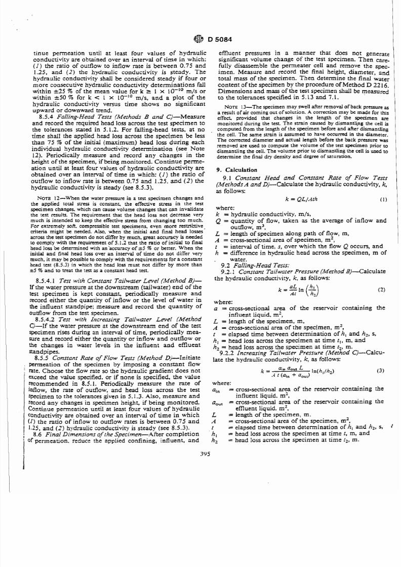
7/27/2019 AStandard Test Method for Tensile Properties of Geotextiles by the Wide-Width Strip Method
http://slidepdf.com/reader/full/astandard-test-method-for-tensile-properties-of-geotextiles-by-the-wide-width 26/39
tinue permeation until at least four values of hydraulicconductivity are obtained over an interval of time in which:( I ) the ratio of outflow to inflow rate is between 0.75 and1.25, and (-7) the hydraulic conductivity is steady. Thehydraulic conductivity shall be considered steady if four or
mo re consecuuve hydraulic conductivity dete rm inatio ns fallwithin -c35 % of the mean value for k r 1 x 10-lo m/s orwithin k50 % for k < I x LO-'' m/s, and a plot of thehydraulic conductivity versus time shows no significantupward or downward trend.
8.5 - 4 Falling- Head Tests (Methods B and C)- Measureand record the required head loss across the test spe cimen tothe tolerances stated in 5.1.2. For falling-head tests, at notime shall the applied head loss across the specimen be lessthan 75 5% of the initial (maximum) head loss during eachindividual hydraulic conductivity determination (see Note12). Periodically measure and record any changes in theheight of the specimen, if being monitored. C on tinu e perm e-ation until at least four values of hydraulic conductivity are
obtained over an interval of time in which: ( I ) the ratio ofoutflow to inflow rate is between 0.75 and 1.25, and ( 2 ) hehydraulic conductivity is steady (see 8.5.3).
NOTE 12-When the water pressure in a t a t specimen changes andthe applied total stress is constant. the effective stress in the testspecimen changes. which can cause volume changes that can invalidatethe te n results. f h e requirement that the head loss not decrease verymuch is intended to keep the effective stress from changing too much.For extremely soft. compressible test specimens, even more restrihive.criteria might be needed. Also, when the initial and final head lossesacross the t m specimen do not differ by much, great accuracy is neededto comply with the requirement of 5.1.2 that the ratio of initial to finalhead loss be determined with ansaccuracy of 5 % or better. When theinitial and final head loss over an interval of time do not differ very
much, it may be possible to comply with the requiremenu for a constanthead test (8.52) in which the head loss must not differ by more than25 % and to treat the test as a consrant head test.
8.5.4.1 Test with Constant Tailwater Level (Method B)-
If the wa ter pressure at the downstream (tailwa ter) end of thetest specimen is kept constant, periodically measure andrecord either the quantity of inflow or the level of water inthe influent standpipe: measure and record the quantity ofoutflow fro m th e test specimen.
8.5.4.2 Test with Increasing Tailwater Level (MethodC)-If the water pressure at the dow nstre am en d of the testspecimen rises during an interval of time, periodically mea-sure and record either the quantity o r inflow a nd outflow o rthe changes in water levels in the influent and emuentStandpipes.
8.5.5 Constant Rate of Flow Tests (Method D)-Initiate, penneation of the specimen by imposing a constant flowi rate. Choo se the flow rate so the hydraulic gra dien t doe s n ot1 exceed the value specified. or if none is specified, the vaIue
recommended in 8.5.1. Periodically measure the rate ofinflow, the rate of outflow. and head loss across the testspecimen to the tolerances given in 5.1.3. A lso, me asu re a n drecord any changes in specimen height, if being monitored.Continue permeation until at least four values of hydraulicconductivity are obtained over an interval of time in which(I ) the ratio of inflow to outflow rates is between 0.75 and1 1.25, and ( 2 ) hydraulic conductivity is steady (see 8.5.3).
;8.6
Final Dimensionsgf [heSpecimen-.After complet ioni of perm eation. reduce rhe applied confining , influent, an d
efflu ent pressures in a ma nne r that does not generatesignificant volume change of the test specimen. Then care.fully disassemble the permeater cell and remove the spec-imen. Measure and record the final height, diameter, andtotal mass of the specimen. Then determine the final water
con tent of the specimen by the procedure of Me thod D 22 16.Dim ensions a nd m ass of the test specimen shall be measuredto t he tolerances specified in 5.13 and 7.1.
NOTE 13-The specimen may swell after removal of back pressure asa result of air coming out of solution. A correction may be made for thiseffect, provided that changes in the length of the specimenmonitored during the test The strain caused by dismantling the cell is
computed from the length of the specimen before and after dismantlingthe cell. The same strain is assumed to have occurred in the diameter.The corrected diameter and actual length before the back pressure was
removed are used to compute the volume of the ten specimen prior todismantling the cell. The volume prior to dismantling the cell is used todetermine the final dry density and degree of saturation.
9. Calculation
9.1 Constant Head and Constant Rate of Flow Tesrs(MethodsA and D)-Calculate the hydraulic condu ctivity, k,as follows:
where:k = hydraulic conductivity, m/s,Q = quantity of flow, taken as the average of inflow and
outflow, m3,L = length of specimen along path of flow, m,A = cross-sectional area of spe cimen , m2,t = interval of time. s, over which the flow Q occurs, andh = difference in hydraulic head across the specimen, m of.
water.9.2 Falling-Head Tests:9.2.1 Constant Tailwater Pressure (Method BJ-Calculate
the hydraulic conductivity, k, as follows:
where:a = cross-sectional area of the reservoir containing the
influent liquid. m',L = length of the specimen, m,A = cross-sectional area of the specimen, m2,t = elapsed time between determination of h, and h,, s,h, = head loss across the specimen at time t , , m, an d
h, = head loss across the specimen at tim e t2, m.9.2.2 Increasing Tailwater Pressure (Method C)-Calcu-late the hydraulic conductivity, k,as follows:
k = aOul' n(h,/hz).4 t (ain a,,,)
where:
n,, = cross-sectional area of the reservoir containing theinfluent liquid. m2,
a,,, = cross-sectional area of the reservoir containing theemuent liquid. m',
L = length of the specimen, rn.A = cross-sectional area o f the specimen, m2,t = elapsed time between determination of h, and h', S, 1
h,=
head loss across the specimen at time t, m, andh, = head loss across the specimen at time r 2 , m.
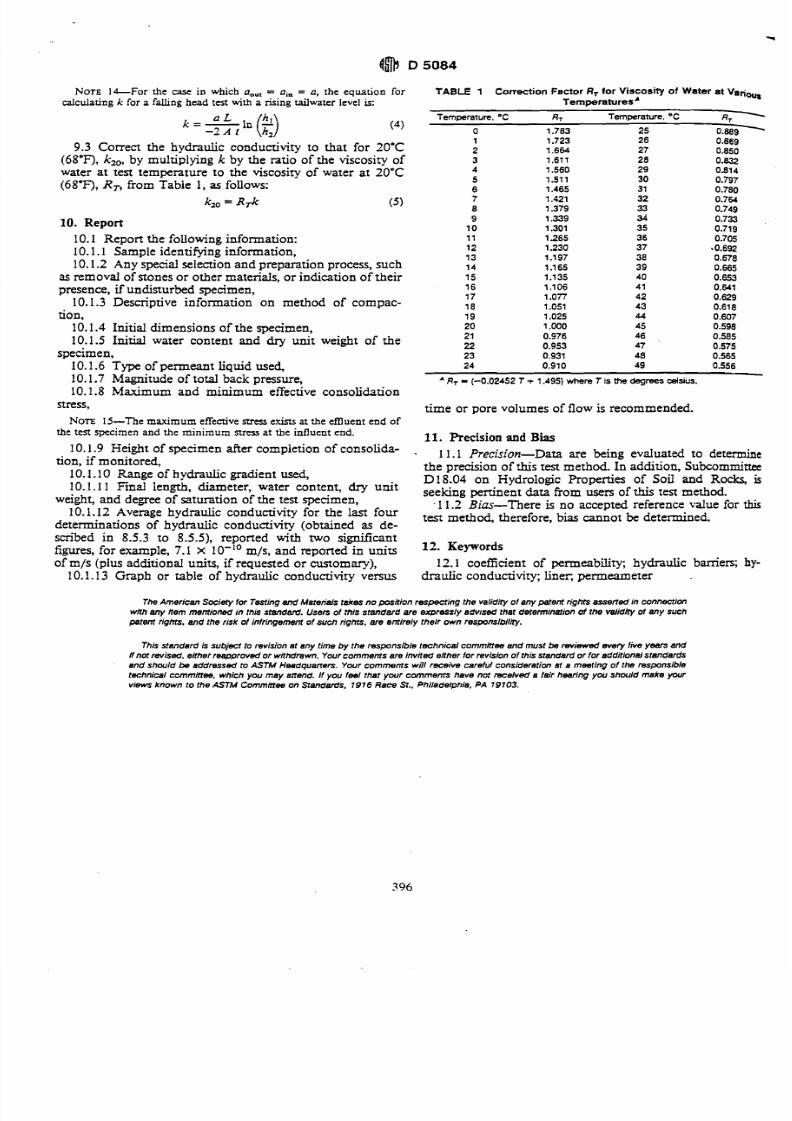
7/27/2019 AStandard Test Method for Tensile Properties of Geotextiles by the Wide-Width Strip Method
http://slidepdf.com/reader/full/astandard-test-method-for-tensile-properties-of-geotextiles-by-the-wide-width 27/39
NOTE b F o r the case in which a,,, = a,, = a, the equation forcalculating k for a falling head test with a rising tailwater level is:
9.3 Correct the hydraulic conductivity to that for 20°C
(68'F), k,,, by multiplying k by the ratio of the viscosity of
water at test temperature to the viscosity of water at 20eC(68'F), R , rom Table 1, as follows:
S o = Rrk ( 5 )
10. Report
10.1 Report the following information:
10.1.1 Sample identifying information,
10.1-2 Any special selection and preparation process, such
as removal of stones or other materials, or indication of their
presence, if undisturbed specimen,
10.1.3 Descriptive information on method of compac-
tion,
10.1.4 Initial dimensions of the specimen,
10.1.5 Initial water content and dry unit weight of thespecimen,
10.1.6 Type of permeant liquid used,
10.1.7 Magnitude of total back pressure,
10.1.8 Maximum and minimum effective consolidation
stress,
NOTE 15-The max imu m effectivemess exim a t the emuent end ofthe test specimen and the minimum stress at the influent end.
TABLE 1 Correction Factor R, for V ~ S C O S ~ ~ ~f Water at Variout
TemperaturesA
Temwrature. OC R, Tem~erature. C R- -
20 1 OOO 45 0.598
21 0.976 46 0.585
22 0.953 47 0.575
23 0.931 48 0.565
24 0.910 49 0.556
* R, = (-0.02452 T+ 1.495) where T is me degrees calsius.
time or pore volumes of flow is recommended.
11. Precision and Bias
10.1.9 Height of specimen after completion of consolida- . are being totion, if monitored,
the precision of this test method. In addition, Subcommittee10.1.10 Range of hydraulic gradient used,
D18.04 on Hydrologic Properties of Soil and Rocks, is10.1.1 1 Find length, diameter, water content, dry unit
seekingertinent from users of this test method.weight, and degree of saturation of the test specimen,
.11.2 Bias--There is no accepted reference value for this
10.1.12 Average hydraulic conductivity for the last four test therefore, bias be determined.determinations of hydraulic conductivity (obtained as de-
scribed in 8.5.3 to 8.5.5), reported with two signif?cant
figures, for example, 7.1 X lo-'' m/s, and reported in units 12. Keywords
of m/s (plus additional units, if requested or customary), 12.1 coefficient of permeability; hydraulic bamen; hy-
10.1.13 Graph or table of hydraulic conductivity versus d r a ~ ~onductivity; liner, permeameter
The American Society for Testingand Materials takes no position respecring the valid* of any patent rights asserted in connection
with any item mentioned in this standard. Usen of this standard are expressly advised that derenninationof the validny of any such
patent rights, and the risk of infringement of such rights. are entirely their own responslbiliry.
This standard is subjeci to revision at any time by the responsible technical commttee and must be reviewed every five yaws and
If not revised. either reapproved or withdrawn. Your comments are invited either tor revision of this standard or for additional standards
and shwld k , addressed to ASTM Headqumem. Your comments will receive careful consideration et a meeting of the responsible
technic81 commaee. which y w may attend. It you feel that yw r cmmem s have not received a fair hearing y w should make your
views known to the ASTM Cornminee on Standards. 1976 Race St.. Philadelphia, PA 79103.
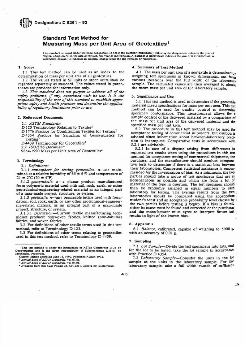
7/27/2019 AStandard Test Method for Tensile Properties of Geotextiles by the Wide-Width Strip Method
http://slidepdf.com/reader/full/astandard-test-method-for-tensile-properties-of-geotextiles-by-the-wide-width 28/39
NbDesignat ion: D 5261 - 92
Standard Test Method for
Measuring Mass per Unit Area of Geotextilesl
This standard is issued under the fixed designation D 5261; the number immediately following the designation indicates the year oforiginal adoption or, in Ihe case of revision, the year of I a n revision. A number in parentheses indicates the year of Ian reapproval. Asuperscript epsilon (t ) indicates an editorial change since the Ian revision or reapproval.
1. Scope
1.1 This test method can be used as an index to the
determination of mass per unit area of a l l geotextiles.1.2 The values stated in SI u i t s or other units shall be
regarded separately as standard. The values stated in paren-
theses are provided for information only.1.3 This standclrd does not purpon to address' all of the
safety problems, if any, associated with its use. I t is the
responsibility ofthe user of this standard to establish appro-
priate safity and health practices and determine the applica-bility ofregulatory limitations prior ro use.
2. Referenced Documents
2.1 ASTM. Standards:D 113 Terminology Relating to TextiIes2
D 1776 Practice for Conditioning Textiles for Testing2
D4354 Practice for Sampling of Geosynthetics for
Testing3
D 4439 Terminology for GeotextiIes32.2 ISO/DIS Document:
9864-1990 Mass per Unit Area of Geotextiles4
3. Terminology
3.1 Dejinirions:3.1.1 atmosphere for testing geotextiles, n-air main-
tained at a relative humidity of 65 5 % and temperature of
21 a 2C (70c 73.
3.1.2 geosyntheric, n-a planar product manufacturedfrom polymeric material used with soil, rock, earth, or other
geotechnical-engineering-relatedmaterial as an integral part
of a man-made project, structure, or system.
3.1.3 georexrile, n-any permeable textile used with foun-
dation, soil, rock, earth, or any other geotechnical-engineer-
ing-related material as an integral part of a man-made
project, structure, or system.
3.1.3.1 Discussion-Current textile manufacturing tech-niques produce: nonwoven fabrics, knitted (non-tabular)fabrics, and woven fabrics.
3.2 For definitions of other textile terms used in this test
method, refer to Terminology D 123.
3.3 For definitions of other terms relating to geotextilesused in this test method, refer to Terminology D 4439.
This t a method is under the jurisdiction of A S M Comminec D 3 5 onGeosynthctia and is the direcl responsibility of Subcomminec D35.01 oaMechanical Ropnies.
Current edition approved June IS. 1992. Published Augun 1992.a Ann& B w k ofASTM Slandards, Vol07.0 1 .'Annual Book of ASTM Slandardr. Vol04.08.
Available from I S0 Care P o d e 56, CH-1211. Geneva 20, Swirzerland.
4. Summary of Test Method
4.1 The mass per unit area of a geotextile is determinedby
w e ia n g test specimens of known dimensions, cut from
various locations over the full width of the laboratorysample. The calculated values are then averaged to obtain
the mean mass per unit area of the laboratory sample.
5. Significance and Use
5.1 This test method is used to determine if the geotex&
material meets specifications for mass per unit area This testmethod can be used for quality control to d e t e especimen conformance. This measurement allows for a
simple control of the delivered material by a comparison of
the mass per unit area of the delivered material and the
specified mass per unit area.
5.2 The procedure in this test method may be used for
acceptance testing of commercial shipments, but caution isadvised since information about between-laboratory preci-
sion is incomplete. Comparative tests in accordance with
5.2.1 are advisable.
5.2.1 In w e of a dispute arising from differences inreponed test results when using the procedures in this testmethod for acceptance testing of commercial shipments, the
piuchaser and the manufacturer should conduct compara-tive tests to determine if there is a statistical bias between
their laboratories. Competent statistical assistance is recom-mended for the investigation of bias. As a minimum, the two
parties should take a group of test specimens that are ashomogeneous as possible and which are from a lot of
material of the type in question. The test specimen should
then be randomly assigned in equal numbers to eachlaboratory for testing. The average results from the two :laboratories should be compared using the appropriate :
student's [-test and an acceptable probability level chosen by :the two parties before testing is begun. If a bias is foundeither its cause must be found and corrected or the purchm
and the manufacturer must agree to interpret future test -results in light of the known bias.
6. Apparatus
6.1 Balance, calibrated, capable of weighing to 5000 &
with an accuracy of 0.01 g.
7. Sampling
7.1 Lot Sample-Divide the test specimens into lots, andfor the Jot to be tested, take the lot sample in accordad=with Practice D 4354.
7.3 Laboratory Sample-Consider the units in the lotsample as the units in the laboratory sample. For the
laboratory sample, take a full width swatch of sufficient
7/27/2019 AStandard Test Method for Tensile Properties of Geotextiles by the Wide-Width Strip Method
http://slidepdf.com/reader/full/astandard-test-method-for-tensile-properties-of-geotextiles-by-the-wide-width 29/39
length along the salvage so that the requiremen ts of 7.3 can 9. Procedure
be met.7.2.1 The laboratory sample shou ld be free from imper-
fections or other areas not representative of the materialsampled.
7.3 The num ber of test specimens shall be a minimum of
five, cu t such that they are represen tative o f the entire rollwidth and with a combined total mi nim um area of 100 000m m 2 (155 in.'). Each test specimen shall be equal in area
(no t less than 10000 mm2 (15.5 in.'), as described inISO/DIS 9864-1990). Cut each test specimen with an accu-racy of 50.5 % of its area,
N o n I-For test spec imens prepared in the fie14 larger thanminimum-sized e s specimens will be required o stay within the cuttingaccuracy (0.5 %). Field expcrien a has shown that a test specimen withan area not less than 90000 mm2 (139.5 in.') will bc necessary toachieve the q u i d ccuracy.
7.3.1 Cu t the test specimens at least on e tenth the width ofthe geotextile from any selvage, unless othen vise spe cified7.3.2
If the structure of the geotextile is such that thespecified test specimen size is not representative of thelabora tory sample, a larger size shall be agreed upon betweenthe purchaser and the supplier.
9.1 Test the conditioned test specimens in the standardatmosphere for testing geotextfies.
9.2 Weigh each of the conditioned specimens separatelyon a calibrated balance to the nearest 0.01 g.
10.1 Calculate the mass per unit area of each of thespecimens as follows:
m =Ms x 1 000 000/A
where:m = mass per unit area round ed to the nearest 0.1 g/m2 ,Ms = mass of the specimen, g, andA = area of the specimen, mm2.
10.2 Repeat this procedure for each test specimen.10.3 Calculate the average and standard deviation of the
mass per unit area results for the test specimens.
11. Report1 1.1 Re por t the following inform ation o n mass per unit
area of geotextiles:11.1.1 Type of geotextile tested, sampling method used,
the test specimen size, shape, and the number of testspecimens tested,
1 . 1.2 The average mass per unit area and standarddeviation to three significant figures, and
I 1. I .3 A statement of any departures from the suggestedtesting procedures so that the results can be evaluated andused.
12. Precision and Bias
8. Conditioning
8.1 Bring the test specimens to m oisture equilibriu m inthe atm osphe re for testing geotextiles. Equilibrium is consid-ered to have been reached when the increase in mass o f thetea specimen in successive weighmgs, made at intervals'ofnot less tha n 2 h, does not exceed k0.1 % of the mass of thetest specimen. In general practice, the indusny approachesequilibrium from the "as-received" side.
N m -It is recognized that in practice geotexrile materials fre-
12.1 precisio n-~he precision of this test method is beingquently arc not weighed to determine when moisture equilibrium hasken reached. While such a proccdm cannot be aaxp tcd in cases of ejtabLished.
dispute, it may be sufficient in routine ttsting to expose the material to 12.2 Bias-This test method has no bias because thethc standard atmosphere for testing for a reasonable period of time value of mass per unit area can only be defined in terms of abcfon the specimens arc tested. A time of at least 24 h has been found test methodacceptable in most cws. owever, certain fibers may exhibit slowmoisture equilibra~on ats from the "asmtivcd"w n side. When this
13+ Keywordsir known, a preconditioning cycle, in accordance with Practice D 1776.may be agrcai up on be we en t he c o n t r a d p an ic s. 13.1 geotextile; mass per un jt area, weight
The American Society tor Testing and M8ter;ats tsk es no pasitian rwpe cring th e validQ of anywentngMs 8ssBRed in connec!ionwith any rtem mentioned in this standard. Users of this standarU are expressly advised thet detenninm'on d he valid@ of any such
petent fights,and the risk ot infringement of such rights. are entirely their own responsiblliry.
This standam' is subject to rwision at any time by the responsible technical cornminee end must k, eviBWBd evwy tive ysan end
if not revised. erthw reapproved or withdrewn. Your commentsare invited either tor revision of this srandsrd or for additional standardsend should te addressed to ASTM HMdqUBR8TS. Your comments will receive carehrl considemtion at 8 meeting at the respomibletechnical cornminee, which you mey attend. If you tesl thet your commenrs have ncf received a lair hearing you should make your
views known to the ASTM Cornmiltee on S tandards. 7976 Rece St.. Philadelphia. PA 19703.
7/27/2019 AStandard Test Method for Tensile Properties of Geotextiles by the Wide-Width Strip Method
http://slidepdf.com/reader/full/astandard-test-method-for-tensile-properties-of-geotextiles-by-the-wide-width 30/39
GEOSYNTHETICESEARCH N S ~ EDrexel UniversityWest Wing - ~ u i hldg. #loPhiladelphia, PA 19104
Drexel
UniLersityn(Adopted October 2,1989)
GRI Test Method GM6
Standard Practice for
"Pressurized Air Channel Testfor DuaI Seamed Geomembranes"
Scope
1.1 The test is intended to provide a nondestructive evaluation of the integity ofgeomembrane seams made in the form of two closely spaced tacks.
1.2 The dual seam itself can be made by a number of methods the most common being thehot wedge technique. Other possible methods are hot air and ulfrasonic bondingtechniques.
The presence of the unwelded channel
for inflation of the sealed channel withlengths of seam can be evaluated, e.g.,
between the two distinct seamed regions allows
air to a predetermined pressure. Extremely longgreater then 100 m (330 ft).
1.4 The tightness of the pressurized air channel over time is noted and recorded
1.5 If air pressure cannot be maintained, a leak in the seam is indicated and correctiveactions are required.
2. Summary
2.1 This method utilizes a dual, or double, bonded seam where an air channel existsbetween the two seam mcks. Both ends of the air channel are sealed with a heat gunand then a hollow needle with attached pressure gauge is inserted into the air space. Air
pressure is applied and the gauge is monitored for excessive air pressure drop.
2.2 Air pressures are related to the thickness and stiffness of the geomembrane and vary
from 165 to 207 kPa (24 to 30 1b/in2).
2.3 Monitoring time is recommended to be 5 minutes.
2.4 Maximum allowable loss of air pressure varies from 14 to 28 kPa (2 to 4 1b/in2)depending upon thickness and stiffness of the geomembrane.
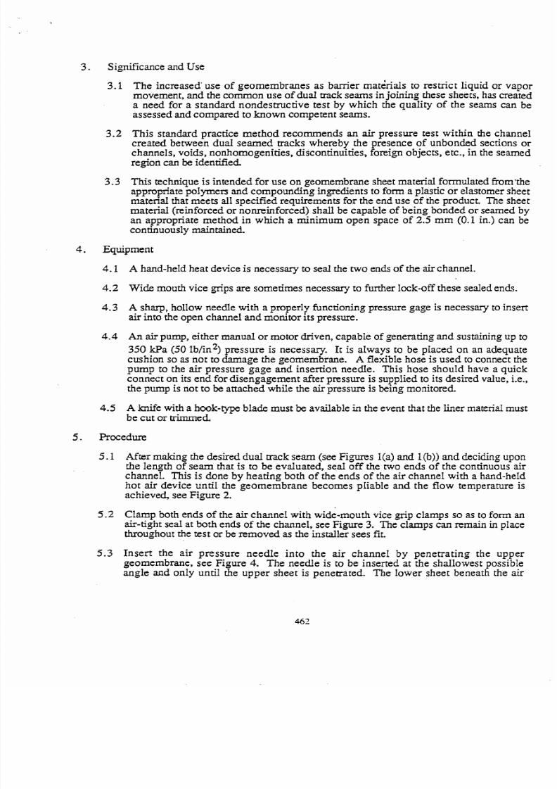
7/27/2019 AStandard Test Method for Tensile Properties of Geotextiles by the Wide-Width Strip Method
http://slidepdf.com/reader/full/astandard-test-method-for-tensile-properties-of-geotextiles-by-the-wide-width 31/39
3. Significance and Use
3.1 The increased' use of geomembranes as barrier matirials to restrict liquid or vapormovement, and the common use of dual track seams in joining these sheets, has createda need for a standard nondestructive test by which the quality of the seams can beassessed and compared to known competent seams.
3.2 This standard practice method recommends a n air pressure test within the channelcreated between dual seamed tracks whereby the presence of unbonded sections orchannels, voids, nonhomogenities, discontinuities, foreign objects, e tc., in the seamedregion can be identified
3.3 This technique is intended for use on geomembrane sheet material formulated from'theappropriate polymers and compounding ingredients to form a plastic or elastomer sheetmaterial that meets all specified requirements for the end use of the product. The sheetmaterial (reinforced or nonreinforced) shall be capable of being bonded or seamed byan appropriate method in which a minimum open space of 2.5 mm (0.1 in.) can becontinuously maintained.
4. Equipment
4.1 A hand-held heat device is necessary to seal the two ends of the air channeI.
4.2 Wide mouth vice grips are sometimes necessary to further lock-off these sealed ends.
4.3 A sharp, hollow needle with a properly functioning pressure gage is necessary to insertair into the open channel and monitor its pressure.
4.4 An air pump, either manual or motor driven, capable of generating and sustaining up to
350 kPa (50 Win2) pressure is necessary. It is always to be placed on an adequate
cushion soas
not to damage the geomembrane. A flexible hose is used to connect thepump to the air pressure gage and insertion needle. This hose should have a quickconnect on its end for disengagement after pressure is supplied to its desired value, i-e.,the pump is not to be attached while the air pressure is being monitored.
A knife with a hmk-type blade must be available in the event that the liner materid mustbe cut or trimmed.
5.1 After making the desired dual track seam (see Figures l(a) and 1 b)) and deciding uponthe length of seam that is to be evaluated, seal off the two ends of the continuous airchannel. This is done by heating both of the ends of the air channel with a hand-held
hot air device until the geomembrane becomes pIiable and the flow temperature isachieved, see Figure 2.
5.2 Clamp both ends of the air channel with wide-mouth vice grip clamps so as to form anair-tight seal at both ends of the channel, see Figure 3. The clamps can remain in placethroughout the test or be removed as the installer sees fit.
5.3 Insert the air pressure needle into the air channel by penenating the uppergeornembrane, see Figure 4. The needle is to be inserted at the shallowest possibleangle and only until the upper sheet is penetrated. The lower sheet beneath the air
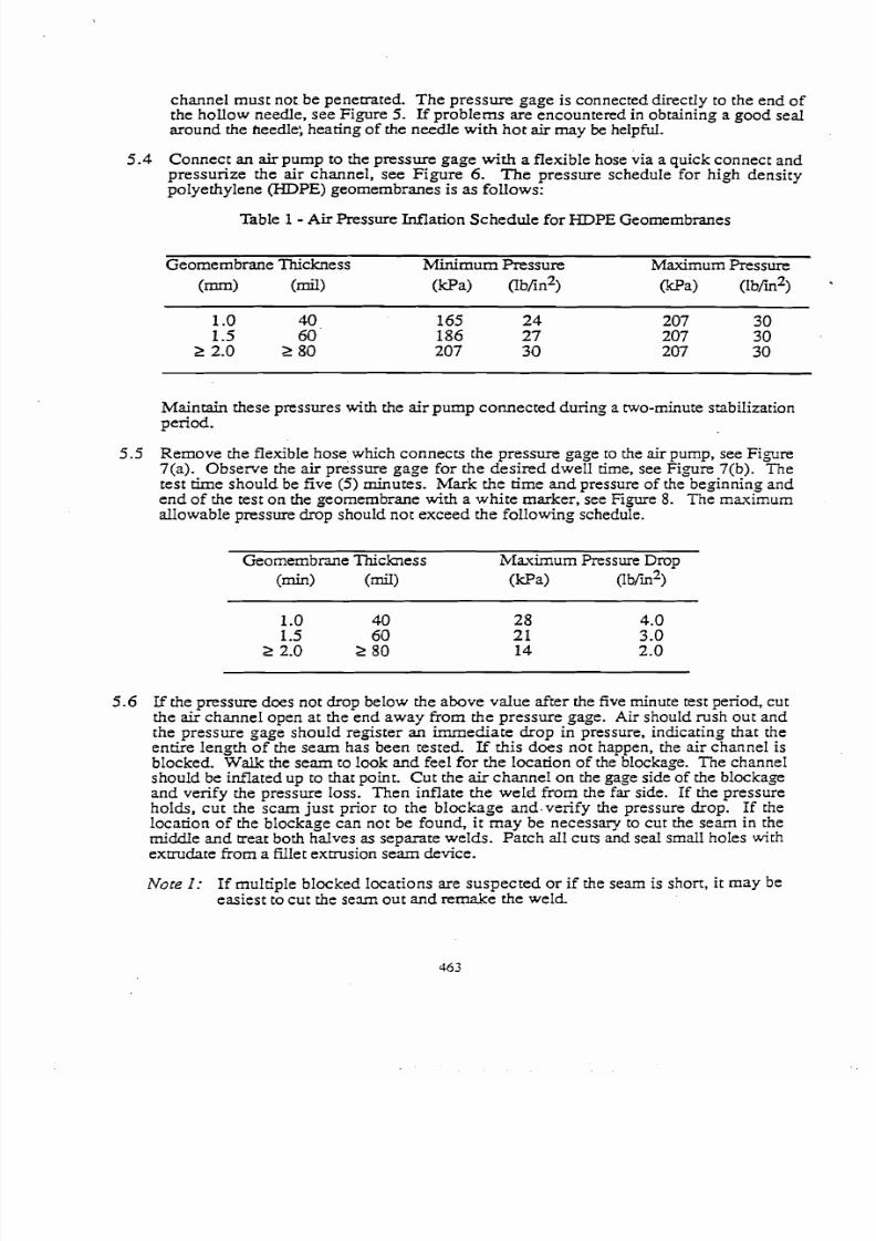
7/27/2019 AStandard Test Method for Tensile Properties of Geotextiles by the Wide-Width Strip Method
http://slidepdf.com/reader/full/astandard-test-method-for-tensile-properties-of-geotextiles-by-the-wide-width 32/39
channel must not. be penetrated. The pressure gage is connected directly to the end ofthe hollow needle, see Figure 5. If problems are encountered in obtaining a good sealaround the heedle; heating of the needle with hot air may be helpfuI.
Connect an air pump to the pressure gage with a flexible hose via a quick connect andpressurize the air channel, see Figure 6. The pressure schedule for high density
polyethylene (HDPE) geomembranes is as follows:
Table 1- Air Pressure Inflation Schedule for HDPE Geomembranes
Geomembrane Thickness Minimum Pressure Maximum Pressure
(mm) (mil) (@a) 0b/in2) (kPa> (lb/in2)
Maintain these pressures with the air pump connected during a two-minute stabilizationperiod.
Remove the flexible hose which connects the pressure gage to the air pump, see Figure7(a). Observe the air pressure gage for the desired dwell time, see Figure 7(b). Thetest time should be five (5) minutes. Mark the time and pressure of the beginning andend of the test on the geomembrane with a white marker, see Fi,oure 8. The maximumallowable pressure drop should not exceed the following schedule.
Geornembrane Th ichess &laximum Pressure Drop
(mid (mil) (@a) (Ifi2)
5.6 Lf the pressure does not drop below the above vdue after the five minute test period, cutthe air channel open at the end away from the pressure gage. Air should rush out andthe pressure gage should register an immediate drop in pressure, indicating that theentire length of the seam has been tested. If this does not happen, the air channel is
blocked. Walk the seam to look and feel for the location of the blockage. The channelshould be infiated up to that point. Cut the air channel on the gage side of the blockageand verify the pressure loss. Then inflate the weld from the far side. If the pressureholds, cut the scam just prior to the blockage and.verify the pressure drop. If thelocation of the blockage can not be found, it may be necessary to cut the seam in themiddie and reat both hdves as separate welds. Patch all cuts and seal small holes withextrudate from a fillet extrusion seam device.
Nore I: If multiple blocked locations are suspected or if the seam is short, it may beeasiest to cut the seam out and remake the weld
7/27/2019 AStandard Test Method for Tensile Properties of Geotextiles by the Wide-Width Strip Method
http://slidepdf.com/reader/full/astandard-test-method-for-tensile-properties-of-geotextiles-by-the-wide-width 33/39
5.7 For a pressure drop greater than the above value, check the end seaIs and where theneedle enters into the air channel. Reseal these are& with a hand held hot air device if aleak is noticed and then repeat the entire test.
Note 2: Leaks around the end seals and air pressure insertion needle can usually belocated by putting moisture around the suspected area and looking for bubbles
to occur.
5.8 If the problem is not located, perform peel tests at the beginning and end of the seam todetermine seam smngth.
5.9 If the seam strength is inadequate, the edge of the loose flap of the upper sheet (whichextends beyond the outer track, recall Figure I) is extrusion fillet welded to the bottomsheet. Thus the extrusion fillet weld becomes the primary seam. It is then vacuum boxtested until satisfactory performance is obtained
If the seam passes the destructive tests, the Ieak is looked for with the flap in place. Ifthe leak is found, it is repaired If it cannot be found, cut away the flap with a hook-type knife as shown in Figure 9. Then vacuum box test the outer track of the seam. If
a leak is found, repair it. Ln both cases, repairs are made by extrusion fillet welds.
5.1 1 If no leak is found in the outer track and all other leak location possibilities have beeneliminated, the leak is assumed to be in the inner aack. Since this inner track is for thepurpose of air channel' testing only, it is redundant and can be ignored. The single goodouter aack is adequate and should be accepted as such.
Note 3: If the outer air aack can notstrip over the entire seam,alternative possibilities.
accepted asthe entire
the primary and onlyseam cut out and re
seam, awelded,
capare
6. Report
6.1 The report of a pressurized dual seam test is usually given in the form of a completedchart. It should include the folIowing information:
date of testtime of testtemperature at time of testlocation of test with respect to panel layout planinitid channel pressureduration of dwell timepressure drop during testoutcome of test (pass/fail)if fail - remedial action is described in detail
6.2 A form as shown in Table 3 includes the above information and may be used for suchreporting.
7. Precision and Bias
7.1 The precision of this test has not been established.7.2 The threshold vdue for accepting seam quality is that value a,ped upon by all parties
overseeing the installation of the project and is thus the source of bias in this procedure.
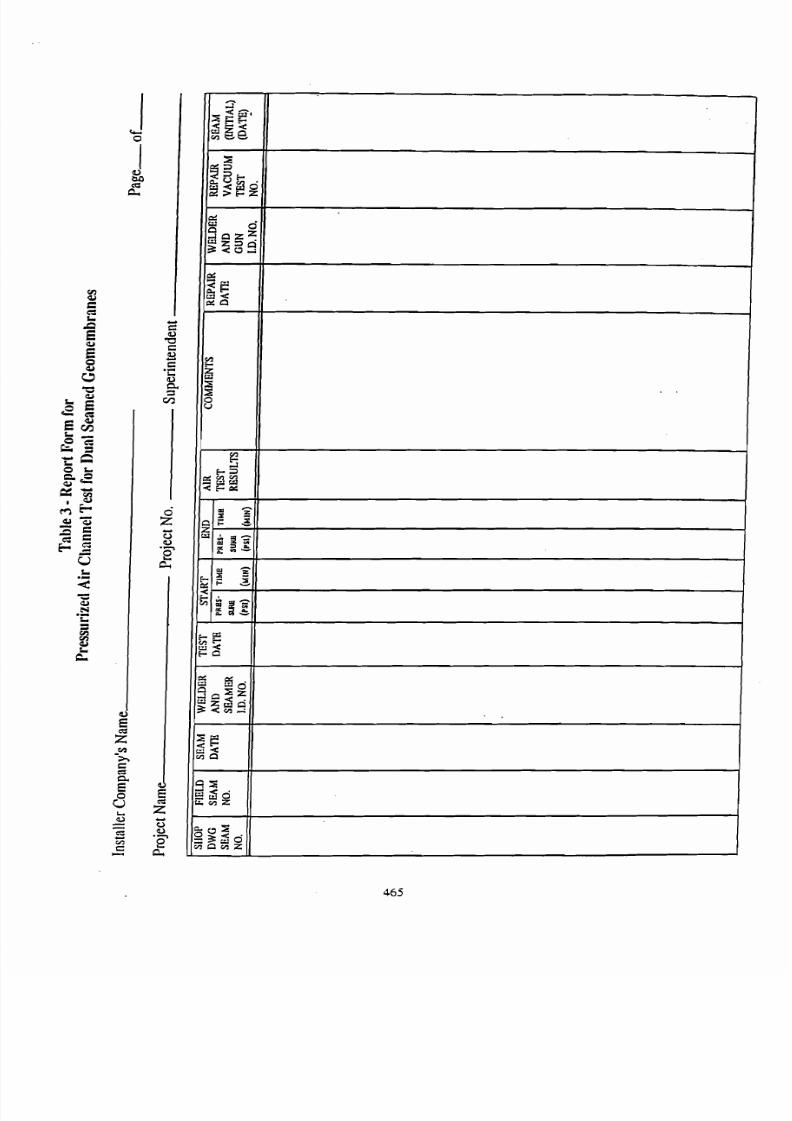
7/27/2019 AStandard Test Method for Tensile Properties of Geotextiles by the Wide-Width Strip Method
http://slidepdf.com/reader/full/astandard-test-method-for-tensile-properties-of-geotextiles-by-the-wide-width 34/39
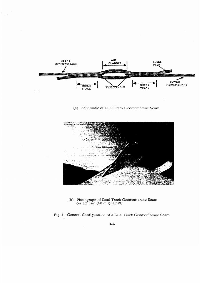
7/27/2019 AStandard Test Method for Tensile Properties of Geotextiles by the Wide-Width Strip Method
http://slidepdf.com/reader/full/astandard-test-method-for-tensile-properties-of-geotextiles-by-the-wide-width 35/39
U P P E R
GEOMEMBRANEI
LOOSE
FLAP,
(a) Schematic of Dual Track Geomembnne Seam
ib) Photograph of Dii:lI Track Gcolnenlbclue Seamoa 1.5nxn (60 mil) HDPE
Fig. 1 - Gelleral Coniigtrration of a Dual Track Geornembrane Seam
466
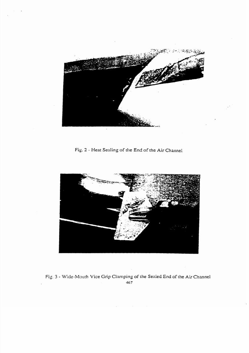
7/27/2019 AStandard Test Method for Tensile Properties of Geotextiles by the Wide-Width Strip Method
http://slidepdf.com/reader/full/astandard-test-method-for-tensile-properties-of-geotextiles-by-the-wide-width 36/39
Fig. 2 - Heat Sealing o f the End of the Air Charinel
Fig. 3 - Wicle-Mouth Vice Grip Clamping of th e Sealed End of the Air Channel
367
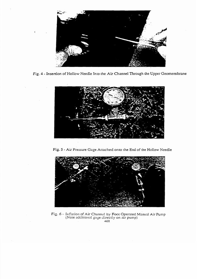
7/27/2019 AStandard Test Method for Tensile Properties of Geotextiles by the Wide-Width Strip Method
http://slidepdf.com/reader/full/astandard-test-method-for-tensile-properties-of-geotextiles-by-the-wide-width 37/39
Fig. 4 - Insertion of H ollow Needle Into the Air Ch anne l Through the Upper Geomernbrane
Fig. 5 - Air Pressure G age Attac hed onto the End of the Hollow Needle
Fig. A - 111lation of Air C h r ~ n n e I y Foot Operated Manual A ir Pump(Note r~dclitionalg : l~ e iirectly o n air pump)
468
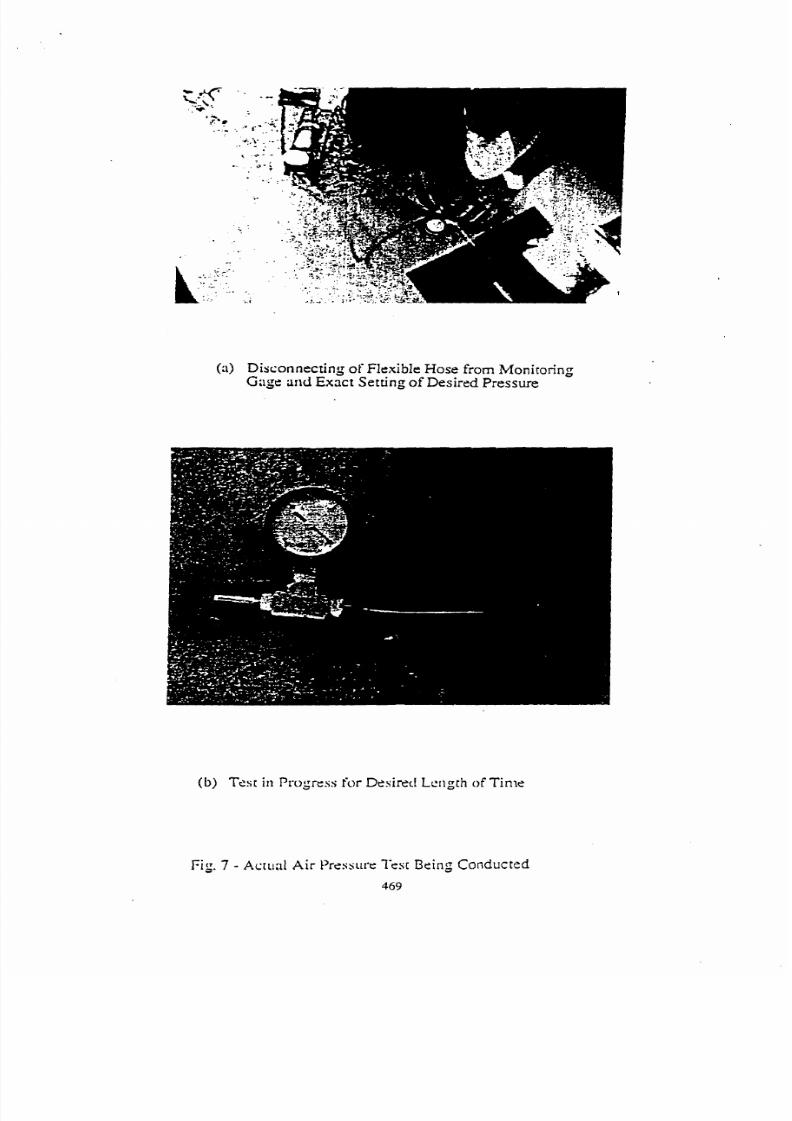
7/27/2019 AStandard Test Method for Tensile Properties of Geotextiles by the Wide-Width Strip Method
http://slidepdf.com/reader/full/astandard-test-method-for-tensile-properties-of-geotextiles-by-the-wide-width 38/39
(a ) Disconnecting of FIexible Hose from MonitoringGage arid Exact Setting of Desired Pressure
(b) Test in Prvgrcss for Dssirsrl L c ~ ~ g r hf Time
Fig. 7 - Actual A ir Przss~lrcis[ Being Conducted
469
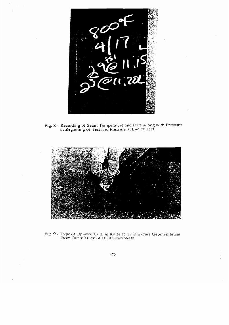
7/27/2019 AStandard Test Method for Tensile Properties of Geotextiles by the Wide-Width Strip Method
http://slidepdf.com/reader/full/astandard-test-method-for-tensile-properties-of-geotextiles-by-the-wide-width 39/39
Fig. 8 - Recordi~lg f S z ; t ~ i ~zniperature an d Dare Along with Pressureat Beginning of Te st arid Pressure at E nd of Test
Fig. 9 - Type of'Upw:u-d Cuttin g Knife to Trinn Escess GeonlembraneFrom Ourer T r a c k o f Dud Se:lrn Weld