Embed Size (px)
Citation preview

cS..RDf Designation: E2307 - 10.u .17
INTE!!NATlONAL
An American National Standard
Standard Test Method torDetermining Fire Resist ance ot Perimeter Fire BarriersUsing lnterrnediate-Scal e, Multi-story Test Apparatus 1
This standard is issued under the fixed designation "2307; ¡he number immediately following the designation indicates the year oforiginal adoption or, in the case of revision, the year of last revision, A number in parentheses indicates the year of last reapproval. Asuperscript epsilon (el indicates an editorial change .iríce the last revision or reapprovaL
INTRODUCTION
A perimeter fire barrier is the peri eter joint protection that pravides fire resistance to preventpassage of tire from floor to floor wi hin the building at the opening between the exterior wallassembly and the f100r assembly. A per meter tire barrier is a unique building construction detail notaddressed by other tire test methods,
Among its other functions, a perimet r tire barrier impedes the vertical spread of tire from the floorof origin to the floor(s) above, at th: building's exterior perimeter and accornmodates variousmovernents such as those induced by t iermal differentials, seismicity, and wind loads.
This test method describes criteria and test methods used to determine the fire resistance ofperimeter tire barriers when subjected to standard fue exposure conditions using the intermediate-scale, multistory test apparatus (ISMA) , The use of the multi-story test apparatus and this test methodare intended to simulate a possible fire exposure on a perimeter tire barrier,
1. Scope1.1 This test method measures the performanc of the
perimeter fire barrier and its ability to maintain seal toprevent tire spread during the defiection and deformati n of theexterior wall assembly and fioor assembly during the tire test,while resisting tire exposure from an interior compart ent fireas well as from the flame plume emitted from the windowbumer below. The end point of the fire-resistance t st is theperiod of time elapsing before the first condition of co plianceis reached as the perimeter tire barrier is subjec ed to atime-temperature tire exposure.
1.2 The tire exposure conditions used are those spe ified bythis test method for the first 30 min of exposure nd thenconform to the Test Methods El19 time-temperature urve forthe rernainder of the test in the test room.
1.3 This test method specifies the heating conditio s, meth-ods of test, and criteria for evaluation of the abi ity of aperimeter tire barrier to maintain the tire resistance where afloor and exterior wall assembly are juxtaposed to a erimeterjoint.
I This test method is under the jurisdiction of ASTM Cornmittee 05 on FireStandards and is the direct responsibility of Subcornmittee E05. 1 on FireResistance.
Currenl edition approved May l. 2010. Published August 2010 Originallyapproved in 2004. Last previous edition approved in 2004 as E2307-04"DOI:10.1520/E2307- ¡O,
1.4 Test results establish the performance of perirneter fuebarriers during the fire-exposure period and shall not beconstrued as having determined the suitabilíty of perimeter tirebarriers for use after that exposure.
1.5 This test method does not provide quantitative informa-tion about the perimeter fire barrier relative to the rate ofleakage of smoke or gases or both. While it requires that suchphenomena be noted and reported when describing the generalbehavior of perimeter tire barrier during the fire-resistance test,such phenomena are not part of the conditions of compliance.
1.6 Potentially important factors and tire characteristics notaddressed by this test method include, but are not limited to:
1.6.1 The performance of the perimeter tire barrier con-structed with components other than those tested, and
l.6.2 The cyclic movement capabilitíes of perimeter fuebarriers other than the cycling conditions tested.
l.7 This test method is used to measure and describe theresponse of materials, products or assemblies to heat and flameunder controlled conditions but does not by itself incorporateall factors required for the fire-hazard or fire-risk assessment ofthe materials, products, or assemblies under actual tire condi-tions.
l.8 The values stated in inch-pound units are to be regardedas standard. The values given in parentheses are mathematicalconversions to SI units that are provided for information onlyand are nat considered standard.
Copyright © ASTM International, 100 Barr Harbor Drive, PO Box C700, West Conshohocken, PA 19428~2959. United States
Copyright by ASTM Int'l (all rights reserved); Tue Aug 2015:55:04 EDT 2013 1Downloaded/printed byJorge Lentino (Obras Metalicas S. A.) pursuant to License Agreernent. No further reproductions authorized.
o E2307 -10
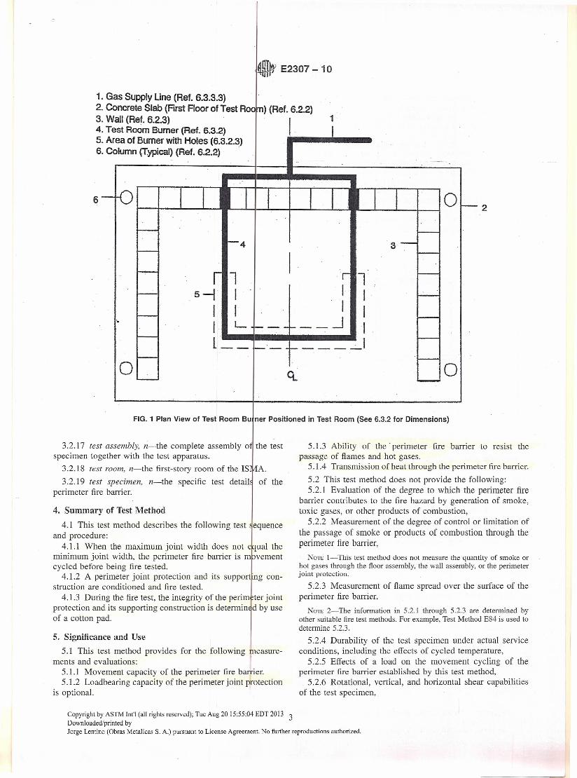
1, Gas Supply Une (Ref. 6.3.3~3)2. Concrete Slab (First Floor of Test Aa ) (Ref. 6.2.2)3. Wall (Ref. 6.2.3) 1 .4. Test Room Sumer (Ref. 6.3.2)5. Area of Sumer with Holes (6.3.2.3)6. Column (T.ypical) (Ref. 6.2.2) .
6
o
4
o--'---'---t---1
3
o
l ls-r I I II I I II L ---' Il~~·--"'_-~~~.I
FIG. 1 Plan View of Test Room Bu ner Positioned in Test Room (See 6.3.2 tor Dimensions)
3.2.17 test assembly, n-the complete assembly o the testspecimen together with the test apparatus.
3.2.18 test room, n-the first-story room of the ISI3.2.19 test specimen, n-the specific test detail
perimeter tire barrier.
A.of the
4. Surnrnary of Test Method
4.1 This test method describes the following test equenceaod procedure:
4.1.1 When the maximum joint width does not ual themínimum joint width, the perimeter tire barrier is vementcycled before being tire tested.
4.1.2 A perimeter joint protection and its support ng con-struction are conditioned and fire tested.
4.1.3 During the fire test, the integrity of the perim ter jointprotection aod its supporting construction is detennin d by useof a cotton pad.
5. Significance and Use5.1 This test method provides for the following ieasure-
ments and evaluations:5.1.1 Movement capacity of the perimeter tire barrier,5.1.2 Loadbearing capacity of the perimeter joint protection
is optional.
2
5.1.3 Ability of the ' perimeter tire barrier to resist thepassage of flames and hot gases.
5.104 Transmission of heat through the perimeter tire barrier.5.2 This test method does not provide the following:5.2.1 Evaluation of the degree to which the perimeter tire
barrier contributes to the tire hazard by generation of smoke,toxic gases, or other products of combustion,
5.2.2 Measurement of the degree of control or limitation ofthe passage of smoke or products of combustion through theperimeter tire barrier,
NOTE l-This test method does not measure the quantíty of smoke orhot gases through the floor assembly, the wall assembly, or the perimeterjoint protection.
5.2.3 Measurement of ñame spread over the surface of theperimeter tire barrier,
NOTE 2-The informatíon in 5.2.1 through 5.2.3 are determined byother suitable fire test methods. For example, Test Method E84 is used todetermine5.2.3.
5.2.4 Durability of the test specimen under actual serviceconditions, including the effects of cycled temperature,
5.2.5 Effects of a load on the movement cycling of theperimeter tire barrier established by this test method,
5.2.6 Rotational, vertical, and horizontal shear capabilitiesof the test specimen,
Copyright by ASTM In!'1 (al! rights reserved); Tue Aug 2015:55:04 EDT 2013 3Downloaded/printed byJorge Lentino (Obras Metalicas S. A.) pursuant to License Agreement. No further reproductions authorized.

o E2307 -10
1. Exterior Wall Assembly or Calibratio Wall (Ref. 7.3 and 9.2)
2. Window (Ref. 7.3.9)
3. Test Frame (Optional)
3
1
--T----- --- •• ------ -<
2
---------._- _.----------------, ,
~on
ITransom
Tes'ppar~tlJs
Vision"",,,
ndreIel
:::::::[-1::::::::-
¡ !
--,<-+, ----lif--.:~::I~I-::.:------.::::::::::- _:::::::::t=-I:::::: :.
~-Mu:¡¡on--
Center Spandrel ConfigurationCenter Mullan Configuration ,
FIG_3 Example 01 an Exterior Wall Assembly with Window Opening in a Test Frame (See 7_3_1)
Copyright by ASTM Int'l (al! rights reserved); Tue Aug 2015:55:04 EDT 2013 5Downloaded/printed byJorge Lentino (Obras Metalicas S. A.) pursuant to License Agreement. No further reproductions authorized.

e E2307 -10
1 I!I--'"o ~ I
'03 3' ,.....- - -3 I._.1 I
1I
1'" . °1,4in(100mm)
PLANVIEW
4
0.75in"(20mm) .
1.18 in·(30 rnrn)
1. Hinge2..Mandle3. 21 Gage(O.5 mrn) Díameter S 'eeI Wire
~. .'
. 4. Hinged Ud with Latch . .5. 16 Gage (1~31mrn) Diameter >teel Wire Framework"
SIDEVIEW '.
NOTE 1: Salid linesillustrate tOOframewarlc. NOTE 2: Dashedlines illustrate he hinged lid..
rTest AssemblyFurnace-
0.79 in. <tI(20 mm)
FIG. 5 Typical eotton Wool Pad Holder (See 6.8.2)
Steel Tube w/I.D.0.2 to 0.4 in.(5 to 10 mm)
--f""1---}-- lMild Stee! Baffl.125 in. (3 mm)
Section View
! --.-0.98 in.
~ ~-:_-__ ~ ~~5mm;
I 5.9 in. l'•. (150rnm) •.
~
o.98in.(25mm) . 2.95in. I
(74mm)--i
Elevation
FIG. 6lT·Shaped Sensor (See 6.10.1.1)
Copyright by ASTM Int'l (al! rights reserved); Tue Aug 2015:55:04 EDT 2013 7Downloaded/printed byJorge Lentino (Obras Metalicas S. A.) pursuant to License Agreement. No further reproductions authorized.
5.9 in.(150 mm}

a,; E2307 - 10'<11
SECTI( N VIEW OF TEST SPEClMEN
A-¡"-3 1-1
\ II ~
1. Exteriortwall Assmebly 2 I(Ref7 3) - 4/'"2. Perimet r Joint A -.JProtection kRef 7.2)3. Flcnr ~ embly (Ref 1.4)4. Thermo ouple Location(fypical) ( ef8.2)5. Centerli e ofTestSpecimen Ref 8.2.2)1.
~ [3I 5
~~~2o o o
IS::CTIONVJEW A-A
FIG. 9 Exposed The mocouple Layout in Test Room (See 8.2)
least 60 in. (1524 mm) wide. Extend 72 ::!:: 1 in. (18.9 ::!:: 25mm) of the test room burner into the test room.
6.3.2.3 Drill upward facing nominal diameter .125-in.(3.2-mm) holes in the pipe. Locate the holes in the f ont "U"shaped portion of the test room bumer. Start holes at a nominallocation of 42 in. (1066 mm) from the back wall on b th sidesof the gas supply pipes and continue across the front gs s supplypipe. Place the holes nomínally 1 in. (25 rryn) on cer ter.
NOTE 8-The holesdrilledare nominalbecause thcy are ma le usingaconventional l/S-in.dril! bit, therefore,their size is dependen!upon thetolerancesof the dril!bit.
6.3.2.4 Support the test room bumer so that it is ley 1and itshorizontal centerline is 30 ::!:: 1 in. (762 ::!:: 25 mm) apoye thefloor of the test room.
6.3.2.5 Center the test room bumer in the test roe m usingFig. 1 for reference.
6.3.2.6 Equip the test room burner with a gas su ply linethat is located outside the test apparatus. Wrap the ehtire gassupply pipe system with a single layer of nomi al l-in.(25-mm) thick ceramic tiber blanket, with 1minimur densityof 8 lb/fe (128 kg/rrr').
6.3.3 Window Bumer:6.3.3.1 Construct the window burner (See Fig. 2 as fol-
lows:
NOTE 9-The window bumer is similar to the one used n U.E.e.StandardNo. 26-9 andNFPA285 and is similarto the bumer sed in the"Spreadof F1ameTest"portíonof TestMethodsEI08.
6.3.3.2 The window burner shall be rectangular shaped. Usea 60 ::!:: 0.5-in. (1524 ::!:: 13-mm) long piece of nominal 2-in.(51-mm) OD pipe for the front of the burner. Cut ad upwardfacing slot having a width and length measuring 0.5 ::!:: 0.06 in.
(13 ::!:: 1.5 mm) by 44 ::!:: 0.5 in. (1118 ::!:: 13 mm), respectively,in the top of the pipe.
6.3.3.3 Supply the window burner with gas at both endsusing nominal l-in. (25-mm) OD pipe and a "T" junction at theback of the window burner to provide uniform gas pressure atthe burner slot.
6.3.3.4 Wrap the window burner, including the slot, and theentíre gas supply pipe system with a layer of nominal 1-in.(25-mm) thick ceramic tiber insulation, with a mínimumdensity of 8 lb/fe (128 kg/nr'),
6.3.3.5 Position the window bumer so that the slot is facingup and parallel with the exterior wall assembly. Align thehorizontal center of the window burner slot with the window'shorizontal centerline (See Fig. 2.). Locate the horizontalcenterline of the wmdow burner 9 ± 0.5 in. (229 ::!:: 13 mm)below the window header's surface on the exterior of the testroom. Place the window burner's vertical centerline a maxi-mum of 6 in. (152 mm) from the exterior face of the exteriorwall assembly. The window burner's exact distance from thewall's exterior face of the exterior wall assembly shall bedetermined during the calibration procedure, as specitied in9.6.
6.4 Cycling Apparatus-Equipment (or device) shall beused that is capable of inducing rnovement of a perimeter tirebarrier as specified in Table 3.
6.5 Test Room and Exterior Wall Assembly Thermocouples:6.5.1 All thermocouples shall be a bare wire type.6.5.2 The twelve test room thermocouples used to measure
the temperatures in the test room, reference the thermocouplesin 8.1, 8.2 and 8.3, shall be 18 gage Type K (See Figs. 8 and9.).
Copyright by ASTM Inrl (al! rights reserved); Tue Aug 2015:55:04 EDT 2013 9Downloaded/printed byJorge Lentino (Obras Metalicas S. A.) pursuanl to License Agreement. No further reproductions authorized.
o E2307 -10
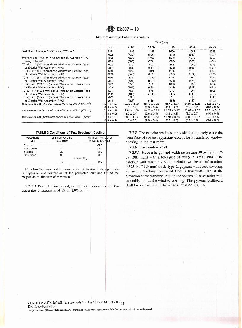
TABLE !Average Calibration Values
Time (min)
0·5 5·10 10·15 15·20 20·25 25·30
Test Room Average °F (Oe) using TC's in 8.1 1151 1346 1482 1600 1597 1648(622) (730) (806) (871) (869) (898)
Interior Face 01 Exterior Wall Assembly Average °F (0C) 1065 1298 1433 1578 1576 1655using Te's in 8.3 (574) (703) (778) (859) (858) (902)
Te #2 . 1 It (305 rnrn) above Window on Exterior Face 602 870 952 992 1046 107801 Exterior Wall Assembly °F(ge) (317) (466) (511) (533) (563) -(581)
TC #3·2 ft (610 mm) above Window on Exterior Face 679 1015 1121 1183 1245 129601 Exterior Wall Assembly °F(Oe) (359) (546) (605) (639) (674) (702)
TC #4·3 ft (914 mm) above Window on Exterior Face 646 971 1096 1174 1245 131401 Exterior Wall Assembly °F(OC) (341) (521) (591) (634) (674) (712)
TC #5 . 4 ft (1219 mm) above Window on Exterior Face 577 858 982 1063 1135 122401 Exterior Wall Assembly °F(OC) (302) (459) (528) (573) (613) (662)
TC #6 . 5 ft (1524 mm) above Window on Ex1erior Face 521 765 875 949 1007 110601 Exterior Wall Assembly °F(°C) (272) (407) (469) (509) (542) (597)
TC #7 . 6 ft (1829 mm) above Window on Exterior Face 472 690 787 856 913 101001 Exterior Wall Assembly °F(OC) (244) (366) (419) (458) (489) (543)
Calorimeter 2 ft (610 mm) above Window W/in.2 (W/cm2) 5. 1 ± 1.29 12.26 ± 2.58 16.13 ± 3.23 18.7 ± 3.87 21.94 ± 4.52 24.52 ± 5.16«(.9 ± 0.2) (1.9 ± 0.4) (2.5 ± 0.5) (2.9 ± 0.6) (3.4 ± 0.7) (3.8 ± 0.8)
Calorimeter 3 ft (914 mm) above Window W/in.2 (W/cm2) 6.5±1.29 12.90 ± 2.58 16.77 ± 3.23 20.65 ± 3.87 23.87 ± 4.52 25.81 ± 5.16(1.0 ± 0.2) (2.0 ± 0.4) (2.6 ± 0.5) (3.2 ± 0.6) (3.7 ± 0.7) (4.0 ± 0.8)
Calorimeter 4 ft (1219 mm) above Window Wlin.2 (W/cm2) 5. 6 ± 1.29 9.68 ± 1.94 12.90 ± 2.58 16.13 ± 3.23 19.35 ± 3.87 21.94 ± 4.52«(.8:!: 0.2) (1.5:!: 0.3) (2.0 :!:0.4) (2.5:!: 0.5) (3.0:!: 0.6) (3.4:!: 0.7)
TABLE 3 Conditions of Test Specimen Cycling
10 400
7.3.8 The exterior wall assembly shall completely close thefront face of the test apparatus except for a simulated windowopening in the test room.
7.3.9 The window shall:7.3.9.1 Have a height and width measuring 30 by 78 in. (76
by 1981 mm) with a tolerance of ±0.5 in. (± 13 rnm). Theexterior wall assembly shall include two layers of nominal0.625-in. (15.9-mm) thick Type X gypsum wallboard coveringan area extending downward from a horizontal line at theelevation of the window lintel to the bottom of the exterior wallassembly minus the window opening. Tbe gypsum wallboardshall be located and fastened as sbown on Fig. 14.
Movement Minimum Cycling Minimum Num ~r 01Type Rates (cpm) Movement Cy les
Thermal 1 500Wind Sway 10 500Seismic 30 100Combined 30 100
lollowed by:
NOTE l-The terms used for movement are indicative of the yclic ratein expansion and contraction of the perimeter joint and n it of themagnitude or direction of movement.
7.3.7.3 Past the inside edges of both sidewalls of theapparatus a minimum of 12 in. (305 mm).
Copyright by ASTM Int'l (al!rights reserved); Tue Aug 2015:55:04 EDT2013 11Downloaded/printed byJarge Lentina (Obras Metalicas S. A.) pursuant to License Agreement. No further reproductions authorized.

1800
200 .
, • .111 E2307 - 10
-,~" "~"".": .-",. - ..:
ISMA TEMP (oF)
E119 TEMP (0F)
FIG. 12 ISMA I E11 Time Temperature Curves (See Note 5)
1. Floor A ssernbly (Ref. 7. 4.)2_ Typical Blackout (Ref 3_2 )
/
nd Elevation ViewFIG. 13 ypical Blockout (See 12.2.4.3)
7.3.10.1 Secure a spandrel beam to the underside of thefloor assembly construction when its use is required to repre-
sent the cornmon construction practice attachment of theexterior wall assembly,
Copyright by ASTM Int'l (al! rights reserved); Tue Aug 2015:55:04 EDT 2013 13
Downloaded/printed byJorge Lentino (Obras Metalicas S. A.) pursuant lo License Agreemenl. No further reproductions authorized.

o E2307 -10
8.2.1 Position at least four bare wire thermoco pIes tomeasure the test room temperature in the vicinity of the testspecimen (See Fig. 9.).
8.2.2 Locate the end of the bare wire thermocouple used tomeasure the temperatures of the side of the test speci en 6 ::t:0.25 in. (305 ::t: 6 mm) exposed to tire from both the u dersideof the perimeter joint protection and the interior face o the testroom of the exterior wal! assembly. LocateTour b e wirethermocouples 24 ::t: 1 in. (610 ::t: 25 mm) apart and sy rnetri-cally distributed from the centerline of the test assem ly (SeeFig. 9.).
8.2.3 Verify the distance established in 8.2.2 at inter als notexceeding 10 min during the first 30 min of the st andthereafter at intervals not exceeding 30 mino
NOTE 11-The rnethod used to accomplish verification of theposition is at the discretion of the laboratory. One possible me od is tomeasure the distance of the thermocouple wire or tube prior to e rnmenc-ing the test and then extend the wire or tube until it touches t interiorface of the exterior wall that is exposed to fue.
8.2.4 Whenever the distance is not as specified i 8.2.2,reset the distance to comply with 8.2.2.
8.3 Interior Face Exterior Wall Assembly Thermoc uples:8.3.1 Place three bare wire thermocouples on the interior
face, exposed to the test room burner, of the exter or wal!assembly. Locate these thermocouples on the horizon 1planethat is 12 ::t: 1 in. (305 ::t: 6 mm) above the window op ning asspecitied in 8.3.2 through 8.3.4.
8.3.2 Place the first one on the intersection of the h rizontalplane and the vertical centerline of the exterior wal! a sembly.
8.3.3 Place the second one on the horizontal plane 24 ::t: 1in. (610 ::t: 25 mm) to the right of the one in 8.3.2.
8.3.4 Place the third one on the horizontal plane 2 ± 1 in.(610 ::'::25 rnm) to the left of the one in 8.3.2.
8.4 Test Room Pressure:8.4.1 The mínimum vertical distance between oressure
sensors, referenced in 6.10, shall be one-half the heig it of thetest room or locate one probe 12 inches below the exposedsurface of the perimeter joint protection. Locate the oressuresensors where they will not be subjected to direct impi igementof convection currents. Tubing connected to each ressuresensor horizontal both in the test room and at its egress throughthe test room wall shall be such that the pressure is r lative tothe same elevation from the inside to the outside of the testroom. I
9. Calibration and Standardization
9.1 Frequency:9.1.1 Perform the following calibration Pfocedure evalu-
ate the fiow rates of the gas burners:9.1.1.1 Prior to product testing, or9.1.1.2 When significant changes to the gas flow systems
are made (that is, new fíow meters, and the like), or9.1.1.3 Within one year prior to the test of an actua product
wall assembly.
9.2 Calibration Wall:9.2.1 Construct the calibration wall for the calibr tion test
of two layers of nominal 0.625-in. (l5.9-mm) thick, Type X
gypsum wallboard applied to both sides of 18-gage steel studsspaced approximately 24 in. (610 mm) on centers. Tape al! buttjoints of the gypsum wallboard. Extend the calibration wall atleast 18 ft (5.49 m) above the floor of the test room and makethe calibration wall at least 14 ft (4.27 m) wide.
NOTE 12-The 14th Edition of the Gypsum Association's Fire Resis-tance Design Manual (GA 600 94) provides a detai1 of this constructiondesignated GÁ FiJe No. WP 1548.'-
9.2.2 Make the interior surface of the window opening ofgypsum wallboard.
9.2.3 Do not use a spandrel beam.9.2.4 Measure the distance from the inside of the back wall
of the test room to the interior face of the calibration wal!.Record this measurement.
9.2.5 When an opening between the test room and thecalibration wall exists, fill it with a ceramic fiber materialhaving a nominal density of at least 8 lb/fe.
9.3 Preparation of Calibration Wall Construction:9.3.1 Before conducting the calibration test, burn away the
paper facing of the gypsum wallboard on the exterior face ofthe calibration wall assembly.
9.3.2 To accomplish this, ignite both the test room burnerand the window bumer while immediately adjusting theburners to their maximum flow rates as prescribed in Table l.
9.3.3 Run the burners for 5 min at these maximum fiowrates and then shut them off.
9.4 As a mínimum, record temperature measurements at thefollowing locations:
9.4.1 At 14 locations on the vertical centerline of the visualface of tbe exterior wall assembly.
9.4.1.1 Place the first bare wire thermocouple 6 ::t: 0.25 in.(152 ± 6 mm) below the top of the window opening.
9.4.1.2 Place the second bare wire thermocouple 18 ::t: 0.25in. (458 ± 6 mm) above the one in 9.4.1.1.
9.4.1.3 Successively place each of the remaining bare wirethermocouples 12 ::t: 0.25 in. (305 ::t: 6 mm) above the onepreviously placed (See Fig. 10.).
9.4.1.4 Successively number the bare wire thermocoupleson the exterior face of the exterior wall assembly 1 through 14.Number the thermocouple in the window opening #1 and thethermocouple at the top of the calibration wall #14. The higherthe location of the thermocouple, the higher the number of thethermocouple.
9.4.2 Place three bare wire thermocouples on the face of thecalibration wall exposed to the test room bumer according to8.3.
9.5 Heat Flux Measurements:9.5.1 Measure the total heat flux at a mínimum of three
locations (See 6.12.).9.5.2 Locate the devices on the face exposed to the test
room burner opposite thermocouples 4, 5, and 6 referenced in9.4.1.4.
9.5.3 Make the devices fiush with the calibration wallsurface that is exposed to the test room.
9.6 Calibration Test Procedure:
Copyright by ASTM In!'] (all rights reserved); Tue Aug2015:55:04EDT 2013 15Downloaded/printed byJorge Lentino (Obras Metalicas S. A.) pursuant to License Agreernent. No further reproductions authorized.

117 E2307 - 10
11.2 Prior to the tire exposure, subject the perim er jomt 12.1.3 Record al! measurements in 12.1.2.protection, which meets the criteria of 11.1, to mcycling. Use appropriate cycling apparatus (See 6.4.)
11.3 The test sponsor se1ects one of the four mtypes desired for the movement cycle test from Tabl
11.4 Install each perimeter joint protection at itsjoint width either together with its supporting consseparate from it. Cycle each perimeter joint protectio accord-ing to the cyclic rate and number of movement cycles selectedby the test sponsor as indicated in 11.3. One cycle co sists ofstarting at the nominal joint width, opening to thejoint width, closing to the mínimum joint width, andto the nominal joint width.
11.5 Do not allow alterations or modifications, wenhance the thermal performance of the perimeprotection, during or after the movement cycling.
11.6 Examine the perimeter joint protection after m vementcycling. Note, photograph, and report any indication f stress,deformation, or fatigue of the test specimen.
11.7 When a perimeter joint protection has been m vementcycled separate1y from its supporting construction, r move itfrom the cycling apparatus, install it in the su portingconstruction,and set it at the maximumjoint width pri r to tiretesting. This process shall not take any longer than 9 h.
12. Fíre-Resístance Test Procedure
12.1 'Test Assembly:12.1.1 Seal the exterior wall assembly against the test
apparatus with an insulating gasket between the wall ssemb1yand the test apparatus. The length of the perime er jointprotection exposed to heat and ñame shall be at least 1 ft. Sealthe open ends of the test specimen against air flow. Th oughoutthe test, check the seals at the ends of the test speci nen andrepair them, as necessary, to prevent air ñow,
12.1.1.1 Measure the distance from the inside of :he backwall of the test room to the interior face of the exte 10r wallassembly that faces the interior of the test room. R ord themeasurement.
12.1.1.2 When the distance recorded in 9.2.4 is differentthan the distance recorded in 12.1.1.1 by more than 2 o do notconduct the tire test. Perform another calibration test ising themeasurement in 12.1.1.1. After performing the re-e librationtest using the distance measured in 12.1.1.1, continu : the firetest procedure.
12.1.2 Protect the test equipment and test assem ily fromany condition of wind or weather that influbnces test results.
12.1.2.1 Measure the ambient air temperature at t e begin-ning of the test; it shall be 40 to 100°F (4.5 to 37.8° :::).
12.1.2.2 Measure the velocity of air moving ho izontallyacross the surface of the test assembly, which will e unex-posed to the tire in the test room, irnmediately befor the testbegins; it is not to exceed 4.4 ft/s (1.3 mis) as determi ed by ananemometer placed at right angles to the unexpose surface.When mechanical ventilation is employed during th test, donot direct an air stream across the surface of the test, ssembly.
12.1.2.3 Measure the hurnidity at the beginning o the test;it is lo be 20 to 80 %.
12.2 Unexposed Surface Temperatures:12.2.1 Provide unexposed surface thermocouples as de-
scribed in 6.6. Measure the temperatures of the unexposedsurface (surface of test specimen opposite the exposure to testroom tire) with thermocouples placed under thermocoupleinsulating pads (See 6.7.). Hold the pad against the surface andfit it about the thermocouple.
12.2.2 When necessary, deform the thermocouple pad tofollow the non-planar surface protile of the test specimen.
12.2.3 Do not place unexposed surface thermocouplescloser to the nearest side wall of the observation room than 1.5times the thickness of the supporting construction or 12 in.(305 rnm), whichever is greater.
12.2.4 Locate unexposed surface thermocouples on the testspecimen as follows:
12.2.4.1 Place at least one on each splice of each perimeterjoint protection, at the rnid-point of the splice (See Fig. 11 Item1.).
12.2.4.2 Place at least three along the longitudinal centerlineof the perimeter joint protection contained between the obser-vation room walls (See Fig. 11 Items 2, 3, 4 and 15.).
12.2.4.3 Place at least two on the adjacent ft.oor assembly ata maximum distance "X," where X is equal to the maximumthickness of the adjacent floor assernbly, from the blockout orjoint edge (See Fig. 13 and Fig. 11 Items 7 and 8.).
12.2.4.4 Place at least two at the junction of the ñoorassembly and perimeter joint protection (See Fig. 11 Items 9,10 and 14.).
12.2.5 When, in the opinion of the laboratory, potentialweak spots are identified, attach additional unexposed surfacethermocouples to these locations. An example of a weak spot isany irregularity, such as a crack or tear that has occurred to thetest specimen during the cycling or the installation process.
12.2.6 Do not locate thermocouples over fasteners (such asscrews, nails or staples) that will be higher or lower intemperature than at a more representative location if theaggregate area of any part of such fasteners on the unexposedsurface is less than 1 % of the area within any 6-in. (lS2-mm)diameter circle, un1ess the fasteners extend through the testspecimen.
12.3 For perimeter joint protection that is designed to beload bearing, apply a superimposed load to the perimeter jointprotection throughout the test. The superimposed load is tosimulate the maximum design load for the perimeter jointprotection (See 6.9.).
12.4 Verífy the operatíon of instrumentation on the com-pleted test assembly.
12.5 Verify the placement of window burner.
12.6 Simultaneously start the measuring devices and dataacquisition equipment at least 1 min before ignition of testroom burner.
12.7 Ignite test room burner.12.7.1 During the tirst 30 min of the test, tire the bumers
according to Table 1.
Copyright by ASTM Int'l (all rightsreserved); Tue Aug 20 15:55:04 EDT2013 17Downloaded/printed byJorge Lentino (Obras Metálicas S. A.) pursuant to License Agreement. No further reproductions authorized.

13.2 Hold the cotton pad directly over an observed rack orhole in the test specimen, approximately 1 in. (25 m 1) fromthe breached surface, for a period of 30 ± 1 s. When r .quired,make small adjustments in the position of the cotton p id to bein the direct path of the hot gasses.
13.3 When no glowing or flaming of the cotton pa occursduring the 30-s application, make "screening tests" .hat (1)involve 30-s duration applications of the cotton pad to sreas ofpotential failure, or (2) involve the movement of the co ton padover and around such areas.
NOTE 18-"Screening tests" are additional application of the e tton padto areas of the perimeter tire barrier that appear to be degrading o a pointwhere ñames or hot gasses appear to be escaping (potential fai ure).
13.4 Where charring of the cotton pad occurs, it is only anindication of a potential failure; apply an unused cot n pad,which must glow or flame as described in 13.3 to dete ine theintegrity failure.
14. Conditions of Compliance
14.1 Movement Cycling Test-When movement econducted, the perimeter joint protection shall have eat least the minimum number of movement cycles usinthe minimum cyclic rate for the movement type sele
14.2 Fire-Resistance Test:14.2.1 "T" Rating-The "T" rating of the perim ter fire
barrier sha11 be deterrnined as the time at which on of thefollowing conditions first occurs:
14.2.1.1 The temperature rise of any of the u xposedsurface thermocouples on the unexposed face of the p erimeterfire barrier or adjacent supporting constructíon as d fined in3.2.16 is more than 325°F (181°C) above th initialtemperature, and
14.2.1.2 For maximum joint widths greater than 4 in. (102mm), the average temperature rise as indicated by 11unex-posed surface thermocouples described in 12.2 is more than2500P (139°C) above the initial temperature.
14.2.1.3 When the test is continued beyond e fire-resistance ratíng of the floor assembly, the unexposed thermo-couples on the floor assembly in 12.2.4.3 shall not b used todetermine the conditions of compliance for the perieter firebarrier.
14.2.1.4 When the indicated fire-resistance ratin : of theperimeter tire barrier is 60 min or more, it shall be inc eased ordecreased by the following correction. The correc .on shallcompensate for significant variation of the measured t est roomtemperature from Test Methods E119 time-tempera re curveprovided that the conditions of 12.7.2.3 are met. To .alculatethe correction factor use the therrnocouples in 8.1. Th : correc-tion is expressed by the following formula:
e = 2I(A - Asl/3(As::':L)
cIing ispleted
at leasted.
where:C correction to the indicated tire resistance in he same
units as 1,1 indicated tire resistance in min,A = area under the actual time-temperature curv for the
first three fourths of the indicated tire resistance in°Fmin (OC'min),
E2307 -10
As the area under the standard time-temperature curve forthe first three fourths for the same part of the indicatedtire resistance in °Fmin (OC·min), and
L lag correction in the same units as A and As,3240oP·min (l800°C-min).
14.2.2 "F" Rating-The "P" rating of the perimeter firebarrier sha11 be determined as the time at which one of thefollowing conditions first occurs:
14.2.2.1 Flame penetration through the perimeter joint pro-tection or around its boundaries, or
14.2.2.2 The passage of flames or hot gases sufficient toignite the cotton pad when applied according to Section 13.
14.3 Integrity Test-The perimeter fire barrier sha11not haveallowed the passage of flames or hot gasses sufficient to ignitethe cotton pad as prescribed in Section 13.
14.4 Load Application-When a load is applied, the perim-eter joint protection shall have sustained that load for theduration of the rating periodo
15. Documentation15.1 Documentation shall consist of the fo11owing:15.1.1 Photographs during construction of the test
specimen, during actual test (at least once every 10 min, withthe time documented), and post-test lo include dissection of thetest specimen.
15.1.2 If requested by the test sponsor, color videotape theexterior face of the exterior wall assembly prior to, during, andpost-test.
15.1.3 Before starting the test, the laboratory identificationnumber and test date must be placed on or in front of theexterior face of the test specimen and shall be photographed.
15.1.4 If requested by the test sponsor, color videotape theunexposed surfaces of the perimeter fire barrier (exterior wallassembly/floor assembly intersection) in the second floorduring the test periodo The color video tape is used to assist indeterrnination of flame penetration and/or smoke developmentthrough the perimeter fire barrier; and
15.1.5 A clock or timer depicting "real time" sha11 beincIuded in a11videos. The timer shall be either:
15.1.5.1 Integral to the video camera, or15.1.5.2 A clock/timer provided it will be clearly viewed
throughout the test
(1)
16. Report16.1 General Injormation-Include:16.1.1 The test date and a reference (that is, project or
laboratory identification) number.16.1.2 As a mínimum, the following about the laboratory or
test facility:16.1.2.1 Name and Location.16.1.2.2 A description of the test apparatus referenced in
6.2.16.2 Include a unique designation for each perimeter fire
barrier tested. Supp1y the fo11owing information for each:16.2.1 Drawings and descriptions of the supporting con-
struction and each perimeter joint protection detailingdimensions, materials, and composition.
Copyright by ASTM Int'l Call rights reserved); Tue Aug 2015:55:04 EDT 2013 19Downloaded/printed byJorge Lentino (Obras Metalicas S. A.) pursuant to License Agreement. No further reproductions authorized.
ASTM Intemational takes no position respecting t validity of any patent rights asserted in connection witn any item mentionedin this standard. Users of this standard are expressly dvised that determination of the validity of any such patent rights, and the rískof infringement of such rights, are entirely their own sponsibility
This standard is subject to revision at any time by t e responsíble technical committee and must be reviewed every five years andif not revised, either reapproved or withdrawn. Your co ments are invited either for revision of this standard or for additional standardsand should be addressed to ASTM Intemational Hea quarters. Your comments wil! receive careful consideration at a meeting of theresponsible technical committee, which you mayatte d. If you feel that your comments have not received a fair hearing you shouldmake your views known to the ASTM Committee on tandards, at the address shown below.
This standard is copyrighted by ASTM Internation ,100 Barr Harbor Drive, PO Box C700, West Conshohocken, PA 19428-2959,Uni/Gid Sta/Gis. Individual mprints (single or mu/lip/e opies) of this standard may be obtained by contacting ASTM al me aboveaddress or at 610-832-9585 (phone), 610-832-9 55 (fax), or [email protected] (e-mail); or through the ASTM website(www.astm.org). Permission rights to photocopy t standard maya/so be secured from the ASTM website (www.astm.org/COPYRIGHT/).
Copyright by ASTM Int'l (al! rights reserved); Tue Aug 20 15:55:04 EDT2013 21Downloadedlprinted byJorge Lentino (Obras Metalicas S. A.) pursuanl lo License Agreemenl. No further reproductions authorized.

1.9 The text of this test method references noes andfootnotes which provide explanatory material. These n tes andfootnotes (excluding those in tables and figures) shal not beconsidered as requirements of the standard.
1.10 This standard does not purport to address a of thesafety concerns, if any, associated witñ its use. 1 is theresponsibility of the user of this standard to establis appro-priate safety and health practices and determine the pplica-bility of regulatory limitations prior to use.
2. Referenced Documents
2.1 ASTM Standards:2
E84 Test Method for Surface Buming Characteri stics ofBuilding Materials
EI0S Test Methods for Fire Tests of Roof CoverinEl19 Test Methods for Fire Tests of Building Con
and MaterialsE176 Terminology of Fire StandardsESl1 Test Metbod for Measuring Heat Flux Using a .opper-
Constan tan Circular Foil, Heat-Flux TransducerE631 Terrninology of Building ConstructionsE1529 Test Methods for Deterrnining Effects of L .ge Hy-
drocarbon Pool Fires on Structural Members and Assem-blies
E1966 Test Method for Fire-Resistive Joint System:I
2.2 Other Documents:Uniform Building Code Standard No. 26-9 Metho of Test
for the Evaluation of Flarnmability Characteri tics ofExterior, Non-Loadbearing Wall Assemblies Co taining .Combustible Components Using the Interrnedi e-ScaleMultistory Test Apparatus''
NFPA 285 Standard Method of Test for the Evalu tion ofFlarnmability Characteristics of Exterior No -Load-Bearing Wall Assemblies Containing Combustib e Com-ponents Using the Intermediate-Scale, Multist ry TestApparatus"
The 14th Edition of the Gypsum Association's Fir Resis-tance Design Manual COA600 94)5
3. Terminology
3.1 Terms defined in Terrninology E176 and E6 1 shallprevail for fue standard and building terrns not define in thisdocumento
3.2 Definitions:3.2.1 blockout, n-a recess formed in the tloor ass mbly to
accornmodate the installation of the perimeter joint pr tection,fíush with the wearing surface of the floor assembly.
2 For referenced ASTM standards, visit the ASTM website, www.a tm.org, orcontact ASTM Customer Service at [email protected]. For Annual Bo o/ AST¡"'!Standards volume information, refer to the standard's Document Summ ry page onthe ASTM website.
3 International Conference of Building Officials Inc., 5360 Workman Mili Rd.,Whittier, es 90601.
4 National Fire Protection Association, 1 Batteryrnarch Park, Quincy, MA02269-9101.
5 Gypsum Association, 810 First Street NE #510, Washington, De 20002.
E2307-10
3,2.2 curtain wall assembly, n-either a rated 01' non-rated,nonbearing exterior wall assembly secured to and supported bythe structural mernbers of the building.
3.2.3 exterior wall assembly, n-a curtain wall or a load-bearing exterior wall that is either tire resistance rated or onethat is not,
3.2.4 fioor assembly, n-a tire resistance rated loadbearinghorizontal separating element adjacent to and separate from thefloor of the observation room.
3.2.4.1 Discussion-Floor assemblies tested in accordancewith Test Methods E119 are required to be loadbearing.
3,2,5 integrity, n-the ability of a perimeter tire barrier,when exposed to tire from two sides, to prevent the passage offiame and hot gases through it and the occurrence of ñames onits unexposed sides as determined by using a cotton pad.
3,2.6 maximum joint width, n-the widest opening of theperimeter joint as defined by the test sponsor,
3.2,7 minimum joint width, n-the narrowest opening of theperimeter joint as defined by the test sponsor.
3,2.8 movement cycle, n-the change between the minimumand the maximum joint widths.
3.2,9 nominal joint width, n-the specified opening of theperimeter joint as defined by the test sponsor that is selected fortest purposes.
3.2,10 observation room, n-the second-story room of theISMA.
3,2,11 perimeter fire barrier, n-the perimeter joint protec-tion that provides fire resistance to prevent the passage of firefrorn floor to tloor within the building at the opening betweenthe exterior wall assembly and the floor assembly. The bound-aries are the edge of the floor assembly and the interior face ofthe exterior wall assembly in contact with the perimeter jointprotection.
3.2.11.1 Discussion-For the purpose of this standard, aknee wall is not to be considered as part of the exterior wall.
3.2.12 perimeter joint, n-the linear void located between ajuxtaposed exterior wall assembly and fioor assembly toaccommodate various movements induced by thermaldifferentials, seisrnicity, wind loads, and rnisalignments of thefioor and wall during construction.
3.2,13 perimeter joint protection, n-a fire-resistive joint. system located between the exterior wall assembly and thefloor assembly that fills the perimeter joint.
3.2,13,1 Discussion-Fil'e-resistive joint system is definedin Test Method E1966.
3.2.14 separating element, n-a floor assembly 01' exteriorwall assembly.
3.2,15 splice, n-the connection or junction within thelength of a perimeter joint protection,
3.2,15,1 Discussion-s-X splice is a result of the device ormethod used to connect or join multiple lengths of theperimeter joint protection.
3.2.16 supporting construction, n-the arrangement of sepa-rating elements forming the intersection into which the perim-eter joint protection is installed,
Copyright by ASTM Int't (all rights reserved); Tue Aug 2015:55:04 EDT 2013 2Downloaded/printed byJorge Lentino (Obras Metalicas S. A.) pursuant to License Agreement. No further reproductions authorized.

~ E2307 -10
1. Window Bumer (Ref. 6.3.3)2. Slot in Bumer (Aef.6.3.3.2)3. Gas Supply Une (Ref. 6.3.3.3)4. Perimeter Joint Protection (Ref. 3.8)5. Window (Ref. 7.3.9)6. Test Room in Test Apparatus (Ref3.18)7. Observatlon Room in Test Apparatus (Ref 3. 3)8. Horizontal Centerline ot Sumer (Ret. 6:3.3.59. Vertical Center[ine of Bumer (Ref. 6.3.3.5)10. Window Sumar location Duríng Test (Ret. ¡.S.S.S)11. Exterior Wa!lAssembly or Calibration Wall Ref. 7.3 and 9.2)12. Test Apparatus (ISMA) (Ref. 6.2) .-- - 1113. Floor Assembly (Aef. 7.4)14. F!oor ot Observation Room (Ref. 6.2.4.2) <i15. Root Slab (Aef. 6.2.2)
2I
l~ 3
Cf.Plan View of Window Bumer
12
I15
-t-i1----6
- I
FIG. 2 Plan View of Window B~ rner and Elevation View of Window Bumer Location
EJevationVlew of Wipdow Bumer Location
5.2.7 Any other attributes of the test specimen, such as wearresistance, chemical resistance, air infiltration, water-tightness,and so forth, and
5.2.8 A measurement of the capability of the test s ecimento resist:
5.2.8.1 Flame propagation over the exterior faces o the testspecimen,
5.2.8.2 Spread of flame within the combustible cc e com-pon<:ntof the exterior wall assembly from one story to he next,
NOTE 3--Some exterior wall assemblies are made from andwichpanels, which use EPS foam or other similar materials that are combus-tible.
5.2.8.3 Spread of flame over the interior surface (ro m side)of the test specimen from one story to the next, and
NOTE 4-WItile it is a failure to have fire on the interior surf ce of theobservation room, this test method does not provide a measurem nt of thatflame spread.
S.2.8.4 Lateral spread of fiame from the compartment of fueorigin to adjacent spaces.
NOTE 5- The exterior wall assembly, floor assembly, and perimeterjoint protection are individual components. The capabilities of individualcomponents are not part of this specific test method's Conditions ofCompliance.
5.3 In this test method, the test specimens are subjected toone or more specific test conditions. When different testconditions are substitnted or the end-use conditions arechanged, it is not always possible by, or from, this test methodto predict changes to the characteristics measured.
5.4 This test method is not intended to be used as the onlytest method in the selection of a perimeter fire barrier. It is notintended as aspecification for a11 attributes required by aperimeter fire barrier, or any of its individual components, inorder for a perimeter fire barrier to be used in a particularapplication.
6. Apparatus
6.1 The test apparatus described in 6.2 shall be locatedinside a test facility. The facility shall have provisions forsupplying fresh combustion make-up air during the test. Thefacility shaIl be constructed to a110w for the exhaust of thecombustion by-products during the test, while not inducingairftow on the exterior face of the test specimen. The testfacility shall protect the test apparatus and test specimen fromweather conditions such as wind and rain.
6.2 Test Apparatus:
Copyright by ASTM Int'[ (al! rights reserved); Tue Aug 2015:55:04 EDT 2013 4Downloaded/printed byJorge Lentino (Obras Metalicas S. A.) pursuant to License Agreement. No further reproductions authorized.

1"--- .Oopoer Disc
csoss SEC'TK)N
0.5 In (12 mm) ameter x 0.008 in (Ó.2 mm) thiel<Copper Disc with 25 :JA (0.5 mm dia) Thennocouple Wire
Thermocouple Wire
lñermocouple Wire
ISOMETFUC
.':.:
...,>-~I===I~...
\ ),/~-'
__ "";"'--1-- Copper Disc
Iflsulating Pad
1.2 x 1.2 x 0.08 in (30 x 30 x :2 mm) Insulating Padwith cuts to a11pa 10 be positioned _over eopper disco
FIG. 4 Typical Copper Therm couple Disc and Insulating Pipe (See 6.6 and 6_7)
6.2.1 The ISMA consists of a two-story testconsisting of a test room and observation room (See ig. 2.).Each room in the test apparatus is square having insid lengthand width dimensions (unfinished and unprotected by any fireresistive materials) of 120 ± 0.5 in. (3048 ± 13 mn ) and aheight (unfinished and unprotected by any fire resistí e mate-rials) of 84 ± 0.5 in. (2134 ± 13 rnm).
NOTE 6-The test apparatus is similar to the one used i U.B.e.Standard No. 26-9 and NFPA 285.
6.2.2 The floors and roof of the test apparatus hall besupported by columns and beams of a size that will su port theload of the ñoor and roof. These supports shall be locatedoutside of both the test room and the observation ro m. Thefloor of the observation room shall be 8 ± 0.5 in. (2 3 ± 13mm) thick (See Fig. 8.).
6.2.3 The three permanent non-bearing walls that f rm eachroom of tbe test apparatus shall support tbe insulatio definedin 6.2.4.1 during the entire fire-resistance test.
NOTE7-Concrete block, 8 ± 0.5 in. (203 ± 13 mm) thick, has beenfound lo be acceptable.
6.2.4 No insulation is required in the observation r 10m; butthe interior surfaces of the test room shall be insulatdd.
6.2.4.1 Insulate the interior face of the walls forming the testroom with one layer of nominal 0.625-in. (15.9-mm) thick,Type X gypsum wallboard and one layer of nominal 1.5-in.(38-mm) thick ceramic fiber insulation, having a minimum
density of 8 lb/ft3 (128 kg/m '), on the interior face. Themaximum insulation thickness permitted on each face is 2.5 in.(64 mm). Insulate the underside of the floor of the observationroom in the same manner, except the portion that is designatedthe "floor assembly," which is adjacent to the perimeter jointprotection, shall not be insulated (See Fig. 2 and 7.4.).
6.2.4.2 Insulate the floor of the test room with two layers ofnominal 0.625-in. (15.9-rnm) thick, Type X gypsum wallboard.
6.2.5 Each room shall have one access opening with a widthand height of nominal 3.5 by 6.75 ft (1.07 by 2.06 m). Theaccess opening of the test room shall be capable of beingclosed during tests while.the access opening of the observationroom shall remain open during tests.
6.2.5.1 Additional access openings are permitted in theobservation room for instrumentation and video; however, theyshal1 be closed during the test.
6.3 Burners:6.3.1 The test apparatus in 6.2shal1 be equipped with two
gas-fired bumers.6.3.2 Test Room Bumer:6.3.2.1 Position the test room burner inside the test room.
Construct the test room bumer (See Fig. 1) as follows:6.3.2.2 Use a nominaI2-in. (51-rnm) OD steel pipe. The test
room bumer shaIl be rectangular shaped with its longitudinalaxis at least 78.75 in. (2000 rnm) long and its transverse axis at
Copyright by ASTM Int'l (all rights reserved); Tue Aug 2015:55:04 EDT 2013 6Downloaded/prinled byJorge Lentino (Obras Melalicas S. A.) pursuanl lo License Agreement. No further reproductions authorized,

., .•. -.:.... ....;..._ :> 6 in.,.. (150 mm) ___ --4__ ~-...,.>2In .. ~ .
(50 mm)/
Standard 1/2-ln, Dlarneter Plpe(Standard 16-mm tnameter Pipe)
4
End welded closed
.Section View B- 8
.Hole (typ)
. Nin1/16~in, (1.5 rnm) dlameter ho/es'spa ed 40 degrees apart aroundíhepfpe ..
B----'
Section View A - A
f:T~sfR om ThermoCo~ple Locatlons (TypicaO(Ref. 8,1) .. 2.FIóoro Test Room (Ref. 6.22) .' ..' .
3. WaU( el. 6.23) ..... . ..4~CoI4m(Typlcal). (Réf~6.2.2)'
Copyright by ASTM Int'l (all rights reserved); Tue Aug 2015:55:04 EDT 2013 8Downloaded/printed byJorge Lentino (Obras Metalicas S. A.) pursuant to License Agreement. No further reproductions authorized.
Enlarg osectíon View A;' A. . . .
FIG. Tube Sensor (See 6.10.1.2)
.0
.0
o 'O'.
3
o 2
o o", .....
FIG. 8 Exposed Thermocouple Layout on Underside of Observation Room Floor in Test Room (See 8.1)

TABLE 1 Gas and Heat Flow Rates
Test Room Test RoomWindow
TimeSurner SCFM Surner
Burr\erInterval
(m3/min) Btu/min (kW) SCFMI(m3/
mín)
0:00 - 5:00 38.0 (1.08) 39064 (687) 0.0 (OOP) O (O5:00 - 10:00 38.0 (1.08) 39064 (687) 9.0 (0.25) 925 (163)10:00 - 15:00 43.0 (1.22) 44204 (777) 12.0 (0.34) 123 6 (217)15:00 - 20:00 46.0 (1.30) 47288 (831). 16.0 (0.45) 16 8 (289)20:00 - 25:00 46.0 (1.30) 47288 (831) 19.0 (0.54) 195 2 (343)25:00 - 30:00 50.0 (1.42) 51 400 (904) 22.0 (0.62) 226 6 (398)
6.5.3 The 14 exterior wall assembly thermocouple used tomeasure the temperatures on the exterior face of the exteriorwall assembly shall be 20 gage Type K (See Fig. 10..
6.6 Copper Disc Thermocouples:6.6.1 The copper disc thermocouples shall be co ered by
pads as specified in 6.7 and shall:6.6.1.1 Have a wire diameter of not more than 0.0 in. (0.7
mm), and6.6.1.2 Be brazed to the center of the face of a cop per disk
having the following nominal measurements: 0.5 in. 12 mm)diameter and 0.008 in. (0.2 mm) thick (See Fig. 4.).
6.7 Thermocouple Insulating Pads:6.7.1 Refractory fiber pads shall have the followin proper-
ties:6.7.1.1 Length and width of 1.20 :.!:::0.02 in. (30:.!::: .5 mm),6.7.1.2 Thickness of 0.08 :.!:::0.02 in. (2 :.!:::0.5 mmu, and6.7.1.3 Density of 56.2 :.!:::6.2 lb/ft3 (900 ± 100 k Im\6.7.2 When necessary, shape the pads by wetting, orming,
and then drying them to provide complete contact on e ntouredsurfaces.
6.8 Cotton Pads:6.8.1 The cotton pad's nominal size shall be 4 by 4 by 0.75
in. (100 by 100 by 19 mm), Cotton pads are to consist of new,undyed, and soft cotton fibers, without any admi ture ofartificial fibers. Each cotton pad shall weigh 3 to g. Thecotton pads are to be conditioned prior to use by dryi g in anoyen at 212 ± 9°F (100 ± 5°C) for at le~st 30 mí . Afterdrying, the cotton pads shall be stored in a dksiccator r up to24 h immediately prior to use. I
6.8.2 The frame used to hold the cotton pad is to b formedof No. 16 AWG (1.31-mm) steel wire and liS to be rovidedwith a handle that will reach all points of the test s ecimenaccessible from the observation room (See Fig. 5.).
6.9 Loading System: I
6.9.1 Use equipment, or device, capable of ind cing adesired load upon the perimeter joint protection.
6.10 Pressure-Sensing Probes-Except for the dia eters ofthe steel tubes, tolerances are :.!:::5 % of dimensions s own 111
Fig. 6 or Fig, 7,6.10.1 The pressure-sensing probes shall be either:6.10.1.1 A T-shaped sensor as shown in Fig. 6, or6.10.1.2 A tube sensor as shown in Fig. 7.
6.11 DijJerential Pressure Measurement Instrumen6.11.1 The differential pressure measurement in trument
shall be:
E2307 -10
6.11.1.1 A manometer or transducer, and6.11.1.2 Capable of reading in graduated increments of no
greater than 0.01 in. H20 (2.5 Pa) with a precision of not lessthan ± 0.005 in. H20 (:.!:::1.25 Pa).
6.12 Calibration Instrumentation:6.12.1 The total heat flux shal! be measured using a mini-
mum of three circular foil heatflux gages (often called Gardongages after the developer).
NOTE lO-More information about the Gardon gage is contained in TestMethodsE511 and E1529.
6.12.2 Flow rate measurement equipment shall be providedfor each of the bumers.
7. Test Specimen7.1 The test specimen shall be representative of the con-
struction for which the fire-resistance rating is desired withrespect to materials, workmanship, and details. Install the testspecimen according to the manufacturer's specified procedurefor conditions representative of those found in building con-struction.
7.2 Perimeter Joint Protection:7.2.1 Test each perimeter joint protection with manufac-
tured and field splices. When the technique of the manufac-tured splice is the same as the field splice, test only one splice.The minimum distance between a splice and the nearest sidewall of the observation room shall be 1.5 times the thickness ofthe supporting construction or 12 in. (305 mm), whichever isgreater. The mínimum separation between splices within a testspecimen shall be 36 in. (914 mm).
7.2.2 Fire test al! perimeter joint protection at its maximumjoint width.
7.2.3 The perimeter joint protection shall be at least 13 ft(4.06 m) long.
7.2.4 When the perimeter joint protection has vertical orhorizontal butt joints or seams as part of its design, these jointsor seams shall be installed according to the manufacturer' sinstructions.
7.3 Exterior Wall Assemblies:7.3.1 The exterior wall assembly shall be a construction
agreed upon by the test sponsor and laboratory (SeeFig. 3.).7.3.2 The exterior wall assembly shall be representative of
that used in common construction practice.7.3.3 The exterior wall assembly shall be secured to the test
apparatus at each end. These fastening details to the testapparatus and those elsewhere within the test specimen shall berepresentative of that used in practice.
7.3.4 Details of the erection shall follow the manufacturer' sinstructions and shall be typical of actual use.
7.3.5 Prior to the test, the exterior wall assembly and itscomponents shall be conditioned as outlined in Section 10.
7.3.6 The mínimum height and width of the exterior wallassembly shall be 17.5 by 13.33 ft (5.34 by 4.06 m wide).
7.3.7 The exterior wall assembly shall extend as follows:7.3.7.1 Below the floor ofthe test room a minimum of2 in.
(51 mm),7.3.7.2 Above the top ofthe test apparatus a minimum of24
in. (610 mm), and
Copyright by ASTM Int'l (al! rights reserved); Tue Aug 20 15:55:04 EDT 2013 10Downloaded/printed byJorge Lentino (Obras Metalicas S. A.) pursuant lo License Agreement, No further rcproductions authorized,

un] E2307 - 10
,l. AoofSlab (Ref.6.2.2)2. Column (Aef.6.2.2) ,"',,3. FIOor of Observaoon Room (Ref. 6.2. )"
'4.Aoo.rof Test Room (Ref.6.2.2) , " '5~WindowOpeni"!9(Ref. 9.2.2)< ' ",,'6., Visual Face 01Calibrátion Wáll (Ref. ,9 ,2) .:7. Vertical Cent~rline, ~f Test.wall(Aef~ .4.1)'8.Thennocouplé#1location (Ret 9.4.11)'9.Thermocouple #2 Location (Ref.9.4.1 2)10. Thermocoupfe #14 Looatlon (Ret9. ~1.4)
FIG. 10 Thermocouple Layout an Visual Exterior Face of Calibration Wall (See 9.4)
4
1. Splic!,! T~ermocoupl~ {R .f. 12.2.4.1}2. Longftudlnal cente, r,!Ine nermocouple {Ref. 12.2.4.2~3. Longitudlnal Cei1terline hermocouple Ret. 12.2.4.24. Longitudinal Centerline rermocouple Ret.12.2.4.25. Junction Therrriocouple - Exterior Wall Assembly & Perimeter Joint Protection (Ret. 12.2.4.3)6. Junction Thermocouple - Exterior Wall Assembry & Perimeter Joint Protection (Ret. 12.2.4.3)7. Floor Assembly Thermo auple ~Aef. 12.2.4.4) ,8. Floor Assembly Thermoc:mple Ref.12.2.4.4) , '9. Junctlon Thermocouple - Floor ssembly & Perímeter Jolnt Protectlon (Ret. 12.2.4.5)10. Junction Thermocouple • Floor Assem51y & Perimeter. Joínt Protection (Aef. 12.2.4.5)11. ExteriorWall Assembly Reí. 7.3) .12. Floor Assembly (Ref. 7. ) ,13. Junction of Exterror Wal Assemblyand Perímeter Jolnt Protection (Ref.12.2.4.3)14. Junction oí F!Qor Asse blv and Perimeter Joint Protection tRef, 12.2.4.5)15. Longitudinal (.;enterfine, f Penmeter Joint Protection (Ref. 12.2.4.2)16. Centerfine of Test Spec en
~ q;~ I '
16
Plan View 01Observa!lon Room Floor al Porlmelar Jolnt Tr~al ni
-5 6
.l. )../'
'-' ~' -16
11
13
12
Interfor Elovation View 01 Observation Room Floor
FIG. 11 Layout of Un xposed Surtace Thermocouples (See 12.2)
7.3.9.2 For the calibration wall, have a sil! height f 30 ::!:0.5 in. (76 ± 13 mm), and for the exterior wall asse bly, theposítion of the window shall be documented in relati n to thebottom of the floor assembly that abuts the perime er jointprotection.
7.3.9.3 Be centered horizontally with respect to the testroom, and
7.3.9.4 Be the only opening in the test room at the start ofthe test.
7.3.10 Spandrel Beam:
Copyright by ASTM Im'[ (al! ríghts reserved); Tue Aug 20 15:55:04 EDT 2013 12Downloaded/printed byJorge Lentino (Obras Metalicas S. A.) pursuant to License Agreement. No further reproductions authorized,
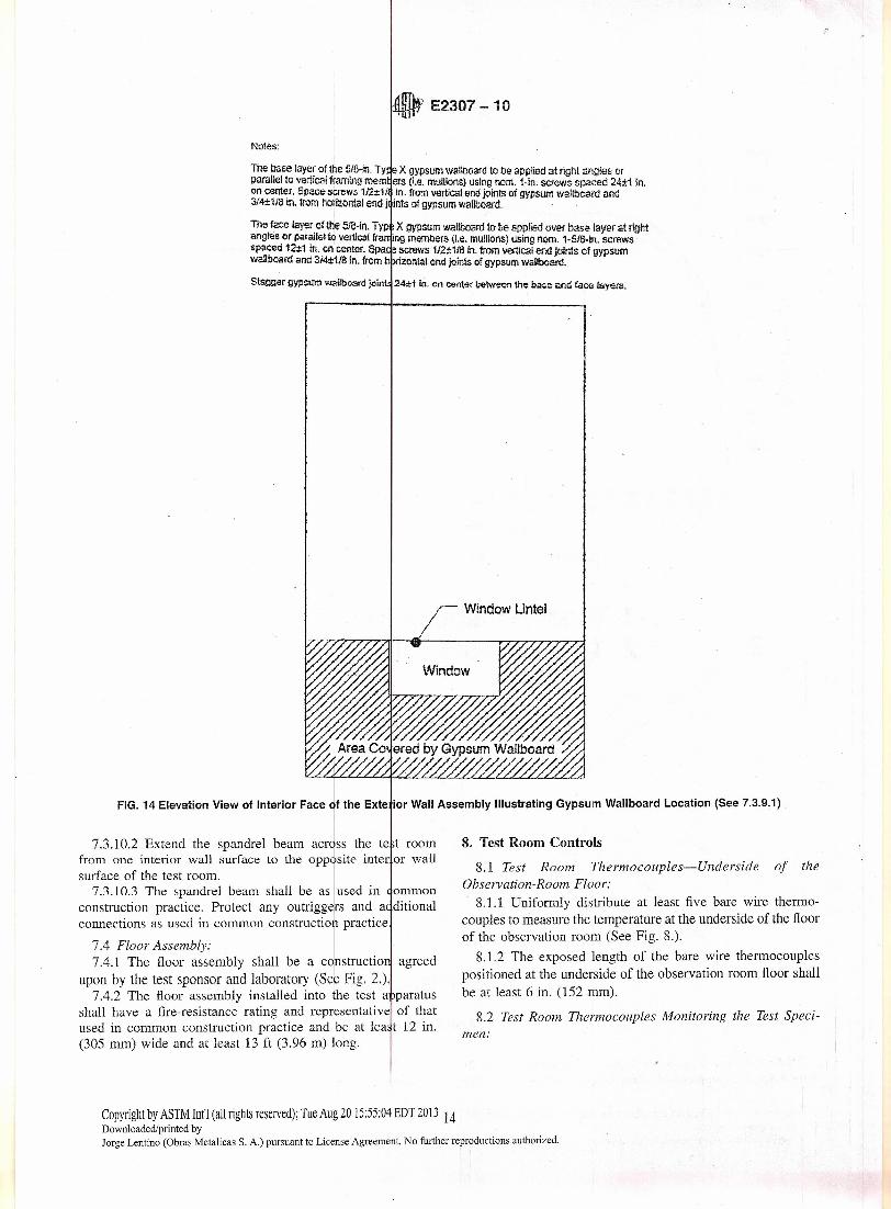
Notes:
The base layer 01!he ~/B·in. Ty X gypsum watlboard to be applied at right llngles orparallello vertical fram¡ngmem ers (Le. mullions) using nom. 1-in. screws spacsd 24±1 in.on center. Space screws 112:t11 in. from vertical end joints of gypsum wallboard and314:t1/e m. trom horiZontal end J ínts of gypsum wallboard.
The faca !¡¡yer 01lhe 518:ln. Typ . X gypsum wallboard to be applied over baselayer at rightangles or par~lJeI te vertical úa tng members (I.e. mullioos) using norn. 1-5/8.in. screws
- - spaced 12:1:1 m, on ce~ter. Spa ~screws 1/2:!:118in. from vertical end jolnts of gypsumwaUboard and 314±1/S 10.from h >lÍzontal end joints of gypsum wallboard.
Stagger gypsum wallboard join 24±t in. <In oenjer between the base and fece ¡ayer:;.
Window Untel
7.3. :~: :x::::M::: V:::n::::t::~.::,t"::: ;~',::A"':b:";~:gc::':: Wallbo"dLocation(S•• 7.3.9.t)
from one interior wall surface to the opposite inter or wallsurface of the test room. I
7.3.10.3 The spandre1 beam shall be as used in ommonconstruction practice. Protect any outriggers and a ditionalconnections as used in common construction practice
7.4 Floor Assembly: I
7.4.1 The floor assembly shall be a constructio agreedupon by the test sponsor and laboratory (Se6 Fig. 2.).
7.4.2 The floor assembly installed into the test a paratusshall have a fire-resistance rating and representative of thatused in common construction practice and be at lea t 12 in.(305 mm) wide and at least 13 ft (3.96 m) long.
8.1 Test Room Thermocouples=Underside of theObservation-Room Floor:
8.1.1 Uniformly distribute at least five bare wire thermo-couples to measure the temperature at the underside of the ñoorof the observation room (See Fig. 8.).
8.1.2 The exposed length of the bare wire thermocouplespositioned at the underside of the observation room floor shallbe at least 6 in. (152 mm).
8.2 Test Room Thermocouples Monitoring the Test Speci-men:
Copyright by ASTM Int'l (al! rights reserved); Tue Aug 20 15:55:04 EDT 2013 14Downloadedlprinted byJorge Lentino (Obras Metalicas S. A.) pursuant to License Agreement. No further reproductions authorized.
17 E2307 -10,.,11
9.6.1 Start the calibration test ancl conduct it so hat thebumers are fired according to Table l. Stabilize each b .irner atits assigned flow rate within 15 s of each change.
NOTE 13-The type of gas used to fuel the burners is n t criticalbecause Tablc 2 provides the temperatures that are to be obtain d duringthe calibration procedure. lf those temperatures obtained during he initialcalibration are not within the tolerance af Table 2, then the cálibrarionprocedure is to be rerun in accordance with 9.10.
9.6.2 For tests up to 30 min in duration, follow Ta ile 1.9.6.3 For tests greater than 30 min in duration, follo Table
1 for the first 30 min then:9.6.3.1 Maintain the window burner at the maxi m gas
flow rate in Table 1 for the remainder of the fire-resista ce test.9.6.3.2 After the first 30 min of a test, if the verage
temperature of the thermocouples in 8.1 in the test oom ismore or Iess than specified in the Test Methods E 11· time-temperature curve, adjust the gas flow to conform to he TestMethods E119 time-temperature curve. See Fig. 8 for ocationof the therrnocouples in 8.1 in the test room.
9.6.4 Conduct the initial calibration test with theburner positioned so that the vertical centerline of theftush with the exterior face of the wall assembly.
9.7 At the conclusion of the calibration test, com 'are thedata obtained to the specified values in Table 2. To preventburner changes from affecting the data, determine the averagevalues for each time period using data from 15 s into th »periodthrough 15 s short of the end of the periodo For. example, if theaverage for the 5-10 min time interval is being proces .ed, usethe data from the actual times of 5: 15 through 9:45 for theaverage.
NOTE l4-When the average calibratian values in Table 2 ar met, thetime-temperature curve during the first 30 min of this tire test will behigher than the standard Test Methods E1l9 time-temperature e rve (SeeFig 12.).
9.8 All of the determined average values for the 1 cationsshown in Table 2 shall fall within the tolerances f thosespeeified in Table 2. The allowable toleranees for the e impari-son of determined average values to the speeified iveragevalues in Table 2 are:
9.8.1 ::t::1O% for temperatures, and9.8.2 As shown in Table 2 for the heat flux measu ements,
9.9 The values for thermocouples 1 and, 8 thro 19h 14,defined by9.4.1.4 and as shown in Fig. 10, ¡shall be r ported,but they are not used in the calibration dete¡ination.
9.10 When the actual test values are not within toler nee. dothe following until the determined values ar~ within to erance:
9.10.1 Repeat the ealibration and the gaslflows, or9.10.2 Adjust the window burner position.
9.11 Use the flow rates deri ved from tJe calibrat on testwhen it is demonstrated that the burners must follow ifferentfiow rates to atta in the following:
9.11.1 The prescri bed test room temperatures, or9.11.2 Exterior temperatures and heat fluxes, or bofh.
9.12 When it is demonstrated that the window buder mustbe repositioned within O and 6 in. (lS2 mm) of the calibrationwall's exterior face to attain the preseribed exterior tempera-
I
Copyright by ASTM Int'l(al!rights reserved); Tue Aug 20 15:55:04 EDT 2013 16Downloaded/printed byJorge Lentino (Obras Metalicas S. A.) pursuant to License Agreement. No further reproductions authorized.
tures and heat fluxes, then use the position derived from thecalibration test in a11subsequent testing.
10. Conditioning
10.1 Prior to testing, condition the test specimen in airhaving 50 % relative humidity at 73 ::t::5°F (23 ::t::3°C). Theobjective of this eonditioning is for the test specimen to reachequilibrium. Do not require the supporting construction to beeonditioned with the perimeter joint proteetion. When condi-tioning to these conditions eannot be accomplished, conductthe testing when the most clamp portion of the supportingconstruction and perimeter joint protectíon have achievedequilibrium resulting from storage in air having 50 to 75 %relative humidity at 73 ::t::5°F (23 ::t::3°C).
10.1.1 Exception-Continue the conditioning only until thesupporting construction has developed sufficient strength toretain the perimeter joint protection secure1y in position whenthe following conditions occur:
10.1.1.1 An equilibrium condition is not achieved within atwelve-month conditioning period, or
1O.l.1.2 The supporting construction or perimeter jointprotection is such that hermetic sealing resulting frorn theconditioning has prevented drying of the interior of thesupporting construction.
10.2 Determine the relative humidity within hardened con-crete with a method that uses an electric sensing elementoDetermine the relative humidity within a supporti.ng construc-tion or test specimen made of materials other than concretewith a method such as one that uses an electric sensingelement.
10.3 Do not use wood with a moisture content greater than13 % as determined by an e1ectrical resistance method.
10.4 When it becomes necessary to use accelerated dryingtechniques, avoid pracedures that will alter the characteristicsof the test specímen from those produced as a result of dryingaccording to the pracedures specified in 10.1.
10.5 Within 72 h of the fire test, obtain information on theactual moisture content and distribution wíthin the test speci-men. When the moisture condition of the test specimen iscapable of changing significantly from the 72-h samplingcondition prior to test, make the sampling not later than 24 hprior to the test.
10.6 Any additional curing regime requested by the manu-facturer and sponsor shall be followed and clearly reported.
10.7 During the cure time, the entire test construction shallbe protected from weather.
11. Movement Cycling Test Procedure
11.1 The test sponsor shall provide the laboratory with thenominal, maximum, and minimum joint width values for theperimeter joint protection being tested. Require movementcycling, when the maximum joint width does not equal theminimum joint width (See 3.2.6 and 3.2.7.).
NOTE l5-A perimeter joint is considered "static" when its maximumand minimum jaint widths are equa1becausc it wiII not move. A perimeterjoint is considered "dynamic" when (he máximum joint width is greaterthan the mínimum joint width because it is capable of movement.

~ E2307-10
12.7.l.1 Each burner shall attain its assigned fl w ratewithin 15 s of each change.
12.7.1.2 When ir is determined by the calibratíon p cedurethat the burners need to follow slightly different flow rates toattain the prescribed test room and/or exterior temperat res andheat fluxes, then the flows derived from the calibrati n testsshall be used.
12.7.2 When a test duration is longer than 30rllÍn,12.7.2.1 Use the Test Methods E1l9 time-temperatu e curve
for the test room for the remainder of the test duration beyond30 mino
12.7.2.2 Follow fiow regime for burners in Table 1 for thefirst 30 mino After the first 30 rnin of a test, if the veragetemperature of the test room thermocouples in 8.1 is ore orless than that specified in the time-ternperature curvc i E119,adjust the gas flow 10 conform to the Test Metho s E1l9time-temperature curve. The gas flow into the test ro m shallnot exceed l.30 times the gas fiow required during the 5:00 to30:00 minute time interval. See Fig. 8 for locatio of thethermocouples in the test room. Leave the window b rner mplace and maintain its last setting (time interval 25:00 30:00)in Table 1 for the remainder of the test.
12.7.2.3 After 30 minutes and when the gas fiow nto thetest room is less than 1.30 times the gas fiow require duringthe 25:00 10 30:00 minute time period, control the test roomburner such that the area under the Test Metho s E119time-temperature curve, obtained using the thermoco iples in8.1, is as follows: Within 10 % of the corresponding ar a underthe Test Methods E 119 time-temperature curve for fire tests of1 h or less duration. Within 7.5 % of the correspond ng areaunder the Test Methods E1l9 time-temperature curve rr thoseover 1 h and not more than 2 h. Within 5 % of the cor espond-ing area under the Test Methods El19 tíme-temperatu e curvefor tests exceeding 2 h in duration.
12.8 Take and record unexposed surface Itemperat res andtest room temperature readings at intervals noltexceedi g 1 minthroughout the test.
12.9 When requested by the test sponsor or at the di cretionof the laboratory, measure and record the Iradiation emittedfrom the unexposed surfaces of the perimeter tire barrier.Document the method used to collect this data.
NOTE 16- The inforrnation collected in 12.9 ma~ be used to establisha database. This database may be used to create futúre test met odologyand criteria, I
12.10 Termination of Test:12.10.1 The fire test shall be terminated for one or ore of
the following reasons:12.10.1.1 Safety of personnel or impending da
equipment.12.10.1.2 Attainment of conditions of compliance.12.10.1.3 Request of sponsor.12.10.2 When requested by the sponsor and agreed t by the
laboratory, continue the fire test after the conditions f com-pliance have been met or exceeded, to obtain additio al data.
12.10.3 When a test is terminated before the conditions ofcompliance are met, the reason for termination shall bedocumented for the test reporto
12.11 Test Room Pressure:12.11.1 Calculate the differential pressure of the test room
based on measurements taken at the specified locations andelevations, and based on the linear pressure gradient of the testroom. Determine the linear pressure gradient of the test roomby the difference in measured pressure of at least two pressuresensors separated by a vertical distance in the test room or usethe reading obtained at the single pressure -probe locationdescribed in 8.4.1.
NOTE 17- The vertical distance does not have to be specified becausethe pressure gradient is linear and can be calculated with any verticaldistance.
12.11.2 Operate the controls such that a minimum pressureof 0.0 1 in. H20 (2.5 Pa) is established at the lowest point of theperimeter joint.
12.11.3 Read and record the ditTerential pressures at inter-vals not exceeding 1 min throughout the test (See 6.10 and6.11.).
12.11.4 After the initial 10 min of fire exposure, control thefumace pressure (at the locations specified) so that it will notbe less than 0.01 in. H20 (2.5 Pa) for:
12.11.4.1 The last 25 % ofthe fire exposure time period and12.11.4.2 An aggregate time period exceeding one of the
following:(1) Ten percent of the tire exposure for fire tests of 1 h or
less duration,(2) Seven and one-half percent of the fire exposure for tire
tests longer than 1 h but not longer than 2 h, and(3) Five percent of the fire exposure for fire tests exceeding
2 h in duration.
12.12 Observations:12.12.1 Make observations of the exposed and unexposed
surfaces of the fioor assembly, perimeter joint protection, andexterior wall assembly throughout the test. At a maximum of15-min time intervals, record observations, such asdeformation, spalling, cracking, burning, and production ofsmoke. When requested by the test sponsor or at the discretionof the laboratory, measure and record defiection of the exteriorwall assembly. Instrumentation for the measurement of deflec-tion shall be located so as to provide data in terms of theamount and rate of deflection during and after the fire test.
12.12.2 When a crack or hole is observed on the unexposedside of the perimeter tire barrier during the test, verify itsintegrity according to Section 13. Record the location, time,and results of each cotton pad application.
12.12.3 Continue the test until the conditions of compliancehave been exceeded or until the test specimen has satisfied al!the applicable requirements in 14.2 for the desired fire-resistance rating.
12.12.4 For the development of additional data, continuingthe test after the fire-resistance rating has been determined shallbe permitted.
13. Integrity Test Procednre13.1 When a crack or hole is observed, evaluate the integrity
of the perimeter tire barrier during the fire-resistance test forpassage of fiame and hot gasses using a cotton pad in a wireframe provided with a handle (See 6.8.).
Copyright by ASTM Int'l (all rights reserved); Tue Aug 2015:55:04 EDT 2013 18Downloaded/printed byJorge Lentino (Obras Metalicas S. A.) pursuant to License Agreement. No further reproductions authorized.

o E2307-10
16.2.2 The curing time, if any, for any components of eachperimeter tire barrier.
16.2.3 The moisture content and the distribution of toisturewithin the test specimen.
16.2.4 The shape and dimensions of recesses (bl ckouts)when formed in the floor assembly to secure any pa t of theperimeter joint protection.
16.2.5 Al! installation procedures provided by he testsponsor, details of the equipment used, and photograp s of theinstallation procedure.
16.2.6 The splicing method used, inc1uding the te t spon-sor's instructions, and photographic documentatíon of theinstallation.
16.2.7 A description of any perimeter joint protectio whichcontains a change in direction (that is, comer). Inc1ude the testsponsor' s installation or fabrication instructions or b th, andphotographic documentation of the installation.
16.2.8 The exterior wall assembly and floor assem ly con-structions (such as the density and type of materials, oisturecontent, special fabrication details). Include the locatio of thewindow opening.
16.2.9 If used, describe the spandrel beam and in ulationused to protect it and any other reinforcement.
16.3 Movement Cycling Test-When movement e cling isconducted, inc1ude the fol!owing information:
16.3.1 The nominal joint width.16.3.2 The maximumjoint width stated by the test ponsor.16.3.3 The minimum joint width stated by the test ponsor.16.3.4 The movement type selected by the test spon or from
Table 3.16.3.5 The minimum number of cycles completed.16.3.6 The cyclic rate (cpm) used.16.3.7 Whether or not 16.3.5 and 16.3.6 for each p rimeter
joint protection satisfies 16.3.4.16.3.8 Photographs of each perimeter joint protectio tested
before, during, and after the movement cycling.16.3.9 Whether the perimeter joint protection wa cycled
either together with its supporting construction or eparatefrom it.
16.4 Fire-Resistance Test:16.4.1 For each perimeter fire barrier telsted, incl de the
following:16.4.1.1 Length and maximum joint width used in the tire
tes~6.4.1.2 The "F-rating" and "T-rating" exJressed in lapsedrninutes, for which the relevant conditions o~ complia 'e havebeen satisfied. Report the tire-resistance rating of t e floorassembly used. Report what type of exterior tall asse ly wasused. When a fire-resistance rated exterior ~all assem ly was
tested, indicate the rating and what test method was used lo ratethe exterior wall assembly.
16.4.2 Report the test room temperatures, the test roompressure data, and a11 time intervals when the test roomtemperature was limited by maximum allowable gas flow.
16.4.3 If applied, report the recorded measurement of thesuperimposed load applied to the perimeter joint protection,method of application, and a photographic 'documentation of itsplacement.
16.4.4 Report the recorded measurement of any deflectionfor each perimeter joint protection and its supportingconstruction, when applicable.
16.4.5 Report any observations made of the surfaces ex-posed and unexposed to tire, such as deformation, spalling,cracking, burning, and production of smoke,
16.4.6 Report the time and reason for termínation of the test(See 12.10.).
16.5 Integrity Test-When the integrity test is conducted,report the results for each perimeter tire barrier. Report whethereach perimeter tire barrier passed or failed. When there was noneed to conduct the integrity test during the fire-resistance test,state that no integrity test was performed because it was notnecessary.
17. Precision and Bias
17.1 Movement Cycling Test-No information is presentedabout either the precision or the bias of this test method formeasuring the response of perimeter joint protections to astandard movement cycle test under controlled laboratoryconditions because no material having an acceptable referencevalue has been determined.
17.2 Fire-Resistance Test-No information is presentedabout either the precision 01' the bias of this test method formeasuring the respon se of perimeter joint protections lo astandard tire test under controlled laboratory conditions be-cause no material having an acceptable reference value hasbeen determined,
17.3 Integrity Test-No information is presented about ei-ther the precision or the bias of this test method for measuringthe response of perimeter joint protections to the integrity testunder controlled laboratory conditions since the test is non-quantitative.
18. Keywords
18.1 construction gap; cycling; curtain waIl; exterior wall;fire; tire 1 resistance; fire-resistí ve joint system; gap;intermediate-scale; multistory test apparatus; joint; linear open-ing; movement; perimeter tire barrier; perimeter joint; perim-eter joint protection; separating element; void
Copyright by ASTM Inl'] (all rights reserved); Tue Aug 2015:55:04 EDT 2013 20Downloaded/printed byJorge Lentino (Obras Metalicas S. A.) pursuant to License Agreement. No further reproductions authorized,


![Total Solution for Oil and Gas Testing [ZH] · 2019-03-20 · astm d3710 astm d7096 astm d5399 astm d2887 astm d5442 astm d7213 astm d6417 astm d6352 astm d5307 astm d7500 astm d7169](https://img.pdfslide.net/doc/110x75/5e70c2f4b4ab9c1c733fd110/total-solution-for-oil-and-gas-testing-zh-2019-03-20-astm-d3710-astm-d7096-astm.jpg)