Embed Size (px)
Citation preview

A Strategic Partner of Thorlabs
CW Fiber LasersPage 1521
Frequency CombsPages 1522 - 1523
ASOPSPage 1524
StabilizationsPages 1525 - 1527
Femtosecond Fiber LasersPages 1528 - 1533
THzPages 1534 - 1538
DetectorsPages 1539 - 1541
www.thorlabs.com1520
01_CW Fiber_Laser_1520-1521.qxd.P:1520-1521 7/25/11 2:43 PM Page 1520

www.thorlabs.com
ITEM # $ £ € RMB DESCRIPTION
orange one-1PM CALL >1 W (up to 2 W)* Single-Frequency Fiber Laser with PM Outputorange one-SHG CALL >200 mW Single-Frequency Fiber Laser with Frequency Doubler**orange one-1 CALL >1 W (up to 2 W)* Single-Frequency Fiber Laserorange one-2 CALL >2 W (up to 4 W)* Single-Frequency Fiber Laser
For local and updated pricing, please call Menlo Systems, Inc. in North America 973-300-4490, Menlo Systems GmbHin Europe +49-89-189-1660, or Thorlabs Japan, Inc. in Asia +81-3-5979-8889, or email [email protected].
orange one – Single-Frequency CW Fiber LaserThe orange one combines a unique ultra-narrow linewidth with high output power toprovide a single-frequency, turnkey, fiber lasersystem. This compact laser package is idealfor applications requiring low noise and stableperformance. The integrated seed laser is asingle frequency fiber laser module fromNKT Photonics. The near infrared outputcan be efficiently converted to the visible in aPPLN waveguide frequency doubler.
Applications Optical Metrology Interferometry High-Resolution Spectroscopy Atom Trapping LIDAR Sensing Optical Data Storage
Specifications
Features Ultra-Narrow Linewidth Stable, Single-Frequency Operation High-Power Output Burst Noise-Free Operation Mode-Hop-Free Tuning Vibration-Free Analog Fine Tuning,
Ready-to-Lock
Digital Coarse Tuning Low Phase Noise and Low Intensity
Noise Single Mode Fiber Output (FC/APC) Stand-Alone Unit in a 19" Rack
System with Integrated Power Supply
orange one
*Specify center wavelength when ordering
*Output power depends on user-selected wavelength **Frequency doubler directly spliced to output of orange one-1PM
Linewidth (120 µs) <100 kHzWavelength Range* 1020 - 1121 nmCenter Wavelength Tolerance ±0.1 nmTemperature Tuning Range >450 pm (-0.3/+0.15 nm), 26 pm °C-1
Piezo Tuning Range >9 pm; 0.1 pm/VPiezo Voltage 0 - 200 VOutput Power 1 W or 2 W (Model and Wavelength Dependent)Output Port PM, Non-PM (1 m Patch Cord Included)ASE Level <10%Power and Environmental Requirements
Operating Voltage 110/115/230 VAC
Frequency 50 to 60 HzPower Consumption 200 WCooling Requirements NoWater Cooling RequiredLaser Head Stabilization Temperature Stabilized with Peltier ElementsOperating Temperature 22 ± 5 °CDimensions 448 mm x 132 mm x 437 mm (17.6" x 5.2" x 17.2")Weight 20 kg
CHAPTERS
Menlo Systems
SECTIONS
CW Fiber Lasers
Frequency Combs
ASOPS
Stabilization
FemtosecondFiber Lasers
THz
Detectors
Light
1521
01_CW Fiber_Laser_1520-1521.qxd.P:1520-1521 7/25/11 2:43 PM Page 1521

www.thorlabs.com
CHAPTERS
Menlo Systems
SECTIONS
CW Fiber Lasers
Frequency Combs
ASOPS
Stabilization
FemtosecondFiber Lasers
THz
Detectors
Light
1522
The FC1500-250-WG Optical Frequency Synthesizer is a compact and flexible fiber-basedfemtosecond frequency comb system. With an extension package for the visible spectral range, thesystem provides a stabilized optical frequency comb for frequency metrology in both the visibleand near infrared spectral regions. A wide range of optional units enables us to tailor this versatilesystem to customer-specific metrology solutions.
The optical frequency comb technology and its stabilization are covered by several internationalpatents (e.g., see EU patent EP 1161782 and US patent 6,785,303 B1). Menlo Systems holds theexclusive rights on the patents. The 2005 Nobel Prize in Physics was awarded to one of thefounders of Menlo Systems, Theodor W. Hänsch, and J. Hall for their invention of the frequencycomb technology.
Specifications
FC1500-250-WG: Er-Doped Optical Frequency Synthesizer
ITEM # $ £ € RMB DESCRIPTION
FC1500-250-WG CALL Erbium Optical Frequency Synthesizer
FC1500-250-WG
The M-NIR extension package amplifies the light fromthe femtosecond fiber laser and then spectrally broadensthe amplified output in a highly nonlinear optical fiber.This supercontinuum comprises a comb of frequencylines, separated by the laser repetition rate and with anarbitrary frequency offset. By phase locking the combspacing and the offset frequency to a radio frequency(RF) reference source, the comb will form an accuratefrequency ruler for the 1050 to 2100 nm region.
The operational range can be extended to the visiblepart of the spectrum by amplifying and frequencydoubling part of the fiber laser output and thenbroadening it in a photonic crystal fiber. The visiblecomb spanning 530 - 900 nm retains the phase stability.
The frequency comb provides a direct link between theoptical and microwave frequencies in both directions.Phase-locked to an RF reference, any unknown opticalfrequency can then be measured by simply comparingits frequency to that of the nearest tooth of thestabilized frequency comb. The accuracy of themeasurement is only limited by the reference.
Conversely, by phase locking one tooth of the frequencycomb to a continuous wave (CW) laser that is locked toa narrow atomic transition or high-finesse resonator, thefrequency comb divides the extremely rapid opticaloscillations of this optical reference to countablemicrowave frequencies.
For local and updated pricing, please call Menlo Systems, Inc. in North America 973-300-4490, Menlo Systems GmbHin Europe +49-89-189-1660, or Thorlabs Japan, Inc. in Asia +81-3-5979-8889, or email [email protected].
Comb Spacing 250 MHzAccuracy* 10-14
Stability* 5x10-13 in 1 sTuning Range of Spacing Between Individual Comb Lines >2 MHzTuning Range of CEO Frequency >250 MHzOptical Output PortsLC/APC Ports – Three Fiber-Coupled, Elliptically PolarizedCenter Wavelength 1560 nmSpectral Range >35 nmAverage Output Power >18 mW from Each Port
Extension Package to the Near InfraredNIR Measurement Port – Free-Space, UnpolarizedSpectral Range 1050 - 2100 nmAverage Output Power >200 mW
Extension Package to the VisibleVIS Measurement Port – Free-Space, UnpolarizedSpectral Range 530 - 900 nmAverage Output Power >60 mW
Additional Amplifier at 1560 nmAverage Output Power >400 mWPulse Length <90 fs
Optional Port at 780 nmAverage Output Power >150 mW
High-Power Measurement Port** HMP633Average Output Power >5 mW
* Same as reference, whichever applies first** In 3 nm window at 633 nm, available for other user-defined wavelengths.
Base Unit• FC1500-250-WG M-Comb oscillator, P250 PULSE-EDFA amplifier, XPS 1500 wave guided f:2f interferometer with electroniccontrol tower
Optional Units• M-NIR extension package extends the stabilized comb spectrum to the 1050 - 2100 nm range• M-VIS extension package extends the stabilized comb spectrum to the 530 - 900 nm range• P250 PULSE-EDFA erbium-doped fiber amplifier for high-power output at 1560 nm• 780 Measurement Port for high-power output at 780 nm• HMP high-power measurement port for high-precision measurement of low-power lasers for user-defined wavelengths• BDU-FS, BDU-FC, and BDU-FF broadband free-space and adjustment-free, fiber-coupled beat detection units• SYNCRO-LLE electronics to phase lock the external CW lasers to the stabilized comb• GPS 5-10 10 MHz frequency reference to serve as RF reference for the frequency comb
02_FrequencyCombs_1522-1523.qxd.P:1522-1523 7/25/11 2:49 PM Page 1522

www.thorlabs.com
CHAPTERS
Menlo Systems
SECTIONS
CW Fiber Lasers
Frequency Combs
ASOPS
Stabilization
FemtosecondFiber Lasers
THz
Detectors
Light
1523
For local and updated pricing, please call Menlo Systems, Inc. in North America 973-300-4490, Menlo Systems GmbHin Europe +49-89-189-166,0 or Thorlabs Japan, Inc. in Asia +81-3-5979-8889, or email [email protected].
FC1000-250: Yb-Doped Optical Frequency SynthesizerFemtosecond optical frequency combs haveled to a revolution in our ability to measurethe frequency of light. This approach vastlyenhances and simplifies dimensionalmetrology and enables new directionsin physics.
With the FC1000-250 we introduce ourlatest model of the Optical FrequencySynthesizer. The FC1000-250 measuresoptical frequencies with unprecedentedaccuracy (up to 14 digits) and stability. It isbased on a mode-locked Ytterbium-doped oscillator and provides 500,000 precise laserlines with equal spacing of 250 MHz. The output is spectrally broadened to generate anoctave-spanning spectrum. The offset frequency beat is generated in a stable, rigid f:2finterferometer. The system is designed and engineered for 24/7 operation.
Specifications
Time Domain - Femtosecond Pulse Train Frequency Domain - Frequency Comb
FC1000-250
ITEM # $ £ € RMB DESCRIPTION
FC1000-250 CALL Ytterbium Optical Frequency Synthesizer
Consecutive pulses and the corresponding spectrum ofthe pulse train emitted by a mode locked laser. Thecarrier wave (shown in blue) shifts by ∆ϕ after eachround trip with respect to the pulse envelope (shown inred). This continuous shift results in a frequency offsetf0=∆ϕ/Τ of the comb.
Stabilization of the offset frequency and the pulse to pulsephase slippage by frequency doubling the infrared part ofthe comb and observation of the beat with the blue part.
OptionsP250 PULSE-YB Yb-Doped Amplifier:Additional amplifier at 1030 nm provides average output power levels in the 500 mW - 1W rangeBDU-FS, BDU-FC, and BDU-FF Beat Detection Units:These units generate and measure the beat signal between the frequency comb and an external CW laser. Available for various spectralranges, these free-space or fiber-coupled units are matched to the laser frequencies of the customer.
SYNCRO-LLE Locking Electronics Unit:This unit phase locks an external CW laser to the stabilized frequency comb and is field-tested using lasers from major suppliers.
GPS 5-10 10 MHz Frequency Reference:Provides RF reference input signal for the frequency comb
Comb Frequency Spacing 250 MHzAccessible Optical Range Octave-Spanning Spectrum Centered at 1030 nmAccuracy* 10-14
Stability* 5 x 10-13 in 1 sInput Requirements 10 MHz Reference, Power Level +7 dBm
*Or same as reference, whichever applies firstNote: When beating the comb with an SM-diode laser (output >2 mW) or any other comparable optical signal, a SNR of >30 dB in 100 kHz bandwidth will be achieved.
Applications Dimensional Metrology Optical Clocks High-Resolution Spectroscopy Low-Noise Microwave Synthesis Absolute Distance Measurements Transfer of Ultrastable Timing
Signal and Frequency Standards
02_FrequencyCombs_1522-1523.qxd.P:1522-1523 7/25/11 2:49 PM Page 1523

www.thorlabs.com
CHAPTERS
Menlo Systems
SECTIONS
CW Fiber Lasers
Frequency Combs
ASOPS
Stabilization
FemtosecondFiber Lasers
THz
Detectors
Light
1524
ITEM # $ £ € RMB DESCRIPTION
ASOPS TWIN 250 CALL 250 MHz ASOPS System for 1560 nmASOPS Dual Color CALL 100 MHz ASOPS System for 1560 and 780 nm
Asynchronous Optical Sampling (ASOPS)The asynchronous optical sampling technique allows high-speed scanning over a few nanoseconds of time delaywithout a mechanical delay line. The ultrafast lasers delivering the pump and probe pulses are locked togetherat a tunable repetition rate difference.
Advantages of the ASOPS technique over conventional sampling techniques requiring a mechanical delay stageinclude faster data acquisition times and the absence of limitations that are common to moving components(e.g., beam pointing instability and limited scanning speed).
Applications Two-Color Pump-Probe Spectroscopy Time-Domain THz Spectroscopy Material Characterization
For local and updated pricing, please call Menlo Systems, Inc. in North America 973-300-4490, Menlo Systems GmbHin Europe +49-89-189-1660, or Thorlabs Japan, Inc. in Asia +81-3-5979-8889, or email [email protected].
SpecificationsWithin the C-Fiber (100 MHz) or M-Fiber (250 MHz) series, any pair of Menlo Systems’ femtosecond fiber lasers can becombined on one platform. Here we specify just two of the possible system configurations.
ASOPS TWIN 250
ASOPS SYSTEM TWIN 250 DUAL COLOR 1560/780Repetition Rate 250 MHz 100 MHzRepetition Rate Offset Tuning Range 1 Hz - 10 kHz 1 Hz - 10 kHzTime Measurement Window 4 ns 10 nsScan Duration* 1 s - 0.1 ms 1 s - 0.1 msData Point Increment** 0.016 - 160 fs 0.1 fs - 1 psRMS Timing Jitter (0.1 Hz - 500 kHz) <150 fs <150 fs
LASER HEADS TWIN M-Fiber Sync C-Fiber Sync C-Fiber Sync 780Wavelength 1560 nm 1560 nm 780 nmAverage Output Power >75 mW (from each laser) >30 mW >65 mWOutput Port Fiber-Coupled FC/APC Free Space Free SpacePulse Length <150 fs after 6 m PM fiber <150 fs 100 - 120 fsTuning Range with Piezo >625 Hz >100 HzPiezo Bandwidth >30 kHz >30 kHzTuning Range with Stepper Motor >2 MHz >330 kHzTrigger Signal TTL level at offset frequency, <25 ns rise time
* Scales inversely with the repetition rate offset **Scales with the ratio of the repetition rate offset and the repetition rate squared (Δf/f 2)
03_ASOPS_1524.qxd.P:1524 7/25/11 2:53 PM Page 1524

www.thorlabs.com
CHAPTERS
Menlo Systems
SECTIONS
CW Fiber Lasers
Frequency Combs
ASOPS
Stabilization
FemtosecondFiber Lasers
THz
Detectors
Light
1525
Specifications
Applications Control Strong-Field Processes in Extreme Nonlinear Optics High Harmonic Attosecond Pulse Generation Phase-Sensitive Experiments
For local and updated pricing, please call Menlo Systems, Inc. in North America 973-300-4490, Menlo Systems GmbHin Europe +49-89-189-1660, or Thorlabs Japan, Inc. in Asia +81-3-5979-8889, or email [email protected].
XPS800 Femtosecond Phase Stabilization
Femtosecond Phase Stabilization
The XPS800 Femtosecond Phase Stabilization Unitgives you control of your ultrashort pulses and theircarrier envelope offset phase.
Operation PrincipleThe pulses from the femtosecond laser are broadenedin a nonlinear photonic crystal fiber to achieve anoctave-spanning spectrum. A nonlinear interferometersubsequently generates the signal for offset frequencystabilization by beating the frequency-doubled infraredpart with the green part of the spectrum. This beatsignal is filtered, amplified, and fed to the lockingelectronics. The offset frequency is phase locked to¼ of the repetition frequency. For this task, therepetition frequency is divided by 4 and sent to Port 1of our digital phase detector. The input for Port 2 ofthe phase detector is the amplified and filtered offsetfrequency signal. A proportional-integral-feedbackcircuit that drives an acousto-optical modulator or apiezo actuator closes the control loop.
ITEM # $ £ € RMB DESCRIPTION
XPS800 CALL Femtosecond Phase Stabilization Unit
ITEM # $ £ € RMB DESCRIPTION
APS800 CALL Amplifier Phase Stabilization Unit
XPS800
Specifications
APS800 Amplifier Phase StabilizationDuring amplification of phase-stabilized femtosecond pulses,slow carrier-envelope phase drifts occur. Menlo Systems’APS800 is used to monitor and stabilize this phase relationafter the amplifier. The APS800 expands full phase control tothe regime of high-power optical pulses used in today’s mostdemanding experiments of attophysics and related areas.
Operation PrincipleTo monitor the slow carrier-envelope phase drifts, a small partof the amplifier output is split off and spectrally broadened in asapphire plate. In an optical interferometer, the green part ofthe resulting octave-spanning spectrum is overlapped with thefrequency-doubled infrared part.
With the help of a spectrometer and control softwarealgorithms, the resulting interferogram is analyzed, and a slowcorrection signal is generated. This signal is fed into thecorresponding input port of the phase stabilization electronicsXPS800 or similar control electronic setups.
APS800
The phase stabilization technology is covered by severalinternational patents (e.g., see EU patent EP 1161782 and USpatent 6,785,303 B1). Menlo Systems holds the exclusive rightson these patents and is proud to have a close collaboration withmajor laser companies that use these products and our patentedtechnology as OEM integrators.
Repetition Frequency 70 - 90 MHzOffset Frequency 1/4 of the Repetition FrequencyLinewidth Offset Frequency < 1HzInput Requirements 200 mW Average Power in <15 fs PulsesOptical Breadboard Dimensions 360 mm x 460 mm (14.2" x 18.1")Stabilization Electronics in 19" Rack
Amplifier Carrier Wavelength 800 nmEnergy Fluctuations <1% (Pulse-to-Pulse, rms)Repetition Rate 1 - 10 kHzInput Energy >10 µJ/PulsePulse Length <50 fsBeam Diameter 5 - 15 mm
Optical Setup Dimensions 410 mm x 230 mm x 140 mm(16.1" x 9.1" x 5.5")
04_PhaseStabilization_1525-1527.qxd.P:1525-1527 7/25/11 3:03 PM Page 1525
www.thorlabs.com
CHAPTERS
Menlo Systems
SECTIONS
CW Fiber Lasers
Frequency Combs
ASOPS
Stabilization
FemtosecondFiber Lasers
THz
Detectors
Features Full Automation High Bandwidth Up to 1.5 MHz (3 dB) Bandwidth Depends on Other Components
in the Complete Control Loop “Track” Function for Long-Term Operation
(Slow Integrator) User-Friendly Operation Front Panel Touch Screen or Remote Control
with PC (RS232 or USB) 2 Stage Locking Scheme
SYNCRO: Platform for Locking Applications
SYNCRO-RRE
The modular design of our new locking electronics allows us toconfigure the phase lock loop for various locking tasks.Developed to serve in our optical frequency comb systems forrepetition rate and offset frequency stabilization, it can be used tophase lock various external devices, such as lasers, cavities, orfiber-links, in today’s most demanding experiments. The formerRRE100 repetition rate synchronization electronics can bereplaced by the new SYNCRO platform.
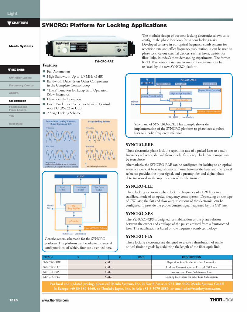
SYNCRO-RREThese electronics phase lock the repetition rate of a pulsed laser to a radiofrequency reference, derived from a radio frequency clock. An example canbe seen above.
Alternatively, the SYNCRO-RRE can be configured for locking to an opticalreference clock. A beat signal detection unit between the laser and the opticalreference provides the input signal, and a preamplifier and digital phasedetector is used in the input section of the electronics.
SYNCRO-LLEThese locking electronics phase lock the frequency of a CW laser to astabilized mode of an optical frequency comb system. Depending on the typeof CW laser, the fast and slow output sections of the electronics can beconfigured to provide the proper control signal requested by the CW laser.
SYNCRO-XPSThe SYNCRO-XPS is designed for stabilization of the phase relationbetween the carrier and envelope of the pulses emitted from a femtosecondlaser. The stabilization is based on the frequency comb technology.
SYNCRO-FLSThese locking electronics are designed to create a distribution of stableoptical timing signals by stabilizing the length of the fiber-optic link.
Schematic of SYNCRO-RRE. This example shows theimplementation of the SYNCRO platform to phase lock a pulsedlaser to a radio frequency reference.
Generic system schematic for the SYNCROplatform. The platform can be adapted to severalconfigurations, of which, four are described here.
ITEM # $ £ € RMB DESCRIPTION
SYNCRO-RRE CALL Repetition Rate Synchronization Electronics
SYNCRO-LLE CALL Locking Electronics for an External CW Laser
SYNCRO-XPS CALL Femtosecond Phase Stabilization Unit
SYNCRO-FLS CALL Locking Electronics for Fiber Link Stabilization
For local and updated pricing, please call Menlo Systems, Inc. in North America 973-300-4490, Menlo Systems GmbHin Europe +49-89-189-1660, or Thorlabs Japan, Inc. in Asia +81-3-5979-8889, or email [email protected].
Light
1526
04_PhaseStabilization_1525-1527.qxd.P:1525-1527 7/25/11 3:03 PM Page 1526

www.thorlabs.com
CHAPTERS
Menlo Systems
SECTIONS
CW Fiber Lasers
Frequency Combs
ASOPS
Stabilization
FemtosecondFiber Lasers
THz
Detectors
Applications Characterization of Mode-Locked Lasers Characterization of Control Loops in
Synchronized Systems Timing Distribution Systems in Accelerator
Facilities Optical Communications Systems
Optical Sampling Applications Time-Domain Spectroscopy THz Physics
PNS: Phase Noise System
RF-MixerPhotodiode Bandpass Filter
Pulsed Laser
Reference FrequencySignal
Lowpass Filter
A/D–ConverterPhaseNoise Software
Menlo Systems’ Phase Noise System PNS provides a flexibleapproach for the measurement and evaluation of phase noiseand timing jitter. It can be easily adapted to customerrequirements, like sampling noise floor and frequency range.The system has three different modes of operation: phasenoise detection from RF spectrum analyzer data, phase noisedetection from time domain data, and relative intensity noisedetection. Due to the Phase Noise System's versatility, a widespan of applications can be covered.
In order to be able to measure such low timing jitter values,a detection system with a low enough noise floor and highenough frequency range is required. Additionally, themeasurement of phase noise and timing jitter should be fastand automated. A graphical display of the measurementresults is important as well.
The image to the left shows a measurement of the relativetiming jitter between an example pulsed laser and anultra-low-noise RF reference frequency signal. The setupschematic for the measurement is shown below.
ITEM # $ £ € RMB DESCRIPTION
PNS-1 CALL Phase Noise Software, PC with A/D Converter, Phase Detection Setup
PNS-2 CALLPhase Noise Software, PC and High-Resolution A/D Converter,
Phase Detection Setup with Low-Noise Amplifier
Basic setup for the detection of the timing jitter between a pulsed laser and a RF reference frequency signal. Using a 16-Bitresolution A/D converter the sampling noise floor is -156 dBc/Hz at a sample rate of 1 MS/s.
For local and updated pricing, please call Menlo Systems, Inc. in North America 973-300-4490, Menlo Systems GmbHin Europe +49-89-189-1660, or Thorlabs Japan, Inc. in Asia +81-3-5979-8889, or email [email protected].
The Phase Noise System PNS-1 withthe Phase Detection Setup in a 19"
Rack, A/D Converter, and PC
Light
1527
04_PhaseStabilization_1525-1527.qxd.P:1525-1527 7/25/11 3:03 PM Page 1527

www.thorlabs.com
ITEM # $ £ € RMB DESCRIPTION
C-Fiber CALL fs Fiber Laser, >30 mW @ 100 MHzC-Fiber HP CALL fs Fiber Laser, >150 mW @ 100 MHzC-Fiber A CALL fs Fiber Laser, >250 mW @ 100 MHzM-Fiber CALL fs Fiber Laser, >75 mW @ 250 MHzM-Fiber A CALL fs Fiber Laser, >400 mW @ 250 MHz
C-Fiber/M-Fiber: 1560 nm Femtosecond Fiber Lasers
Applications Time-Resolved Spectroscopy Diagnostics and Imaging in Biology and Medicine Timing Distribution Systems THz Generation, THz Spectroscopy
Specifications
Advanced Features and Benefits Average Output Power: >400 mW @ 250 MHz Pulse Length: <90 fs Synchronization to External Clock Signal Highest Stability, Reliable Operation Truly Turnkey Operation by Self-Starting Mode-Locking
Mechanism Embedded Microcontroller for Trouble-Free Operation Long Lifetime and Low Cost of Ownership
For local and updated pricing, please call Menlo Systems, Inc. in North America 973-300-4490, Menlo Systems GmbHin Europe +49-89-189-1660, or Thorlabs Japan, Inc. in Asia +81-3-5979-8889, or email [email protected].
C-Fiber
C-Fiber Laser SeriesThe C-Fiber laser series consists of erbium-doped fiber lasers, each with a100 MHz repetition rate. They are available with various power levels andoffer a high degree of flexibility, including user-defined repetition rates andfreely configurable optical output ports.
The passively mode-locked, state-of-the-art laser allows turnkey operationthrough an embedded microcontroller and is the ideal choice fordemanding applications in the ultrafast world of science and industry.
The scientific lasers of the C-Fiber and M-Fiber series are also available with an added second harmonic generation stage.Please see C-Fiber/M-Fiber A 780 on page 1529 or visit www.menlosystems.com.
M-Fiber Laser SeriesThe M-Fiber lasers run at a 250 MHz repetition rate on our scientific platform,delivering pulses with power levels above 400 mW.
By adding the SYNC option to the C-Fiber and the M-Fiber series, the cavity length becomestunable, and the repetition rate can be synchronized to an external pulsed source. An integrated steppermotor allows for coarse adjustment, and with the help of the piezo actuator, the repetition rate can be fine tunedand locked to an external reference frequency. For details on the synchronization electronics, see the information on SYNCRO-RRE,which can be found on page 1526.
C-Fiber C-Fiber HP C-Fiber A M-Fiber M-Fiber A
Wavelength 1560 ± 20 nm
Repetition Rate 100 MHz 250 MHz
Average Output Power >30 mW >150 mW >250 mW >75 mW >400 mW
Pulse Width <150 fs <90 fs <150 fs <90 fs
Repetition RateTuning Range* >330 kHz >2 MHz
* with SYNC100 or SYNC250 Option
CHAPTERS
Menlo Systems
SECTIONS
CW Fiber Lasers
Frequency Combs
ASOPS
Stabilization
FemtosecondFiber Lasers
THz
Detectors
Light
1528
05_FemtosecondLaser_1528-1533.qxd.P:1528-1533 7/25/11 3:09 PM Page 1528

www.thorlabs.com
CHAPTERS
Menlo Systems
SECTIONS
CW Fiber Lasers
Frequency Combs
ASOPS
Stabilization
FemtosecondFiber Lasers
THz
Detectors
Light
1529
C-Fiber 780 Laser SeriesBuilding upon the success of our erbium-doped C-fiber laser series, a second harmonic generationstage has been added. This results in a laser with 780 nm centered pulses. The high degreeof flexibility of our C-fiber lasers, including user-defined repetition rates and variablecavity lengths, is also available for this series.
Using an external F-Femtoscale compressor, the C-Fiber 780 can deliver <70 fs pulses.
M-Fiber A 780 LasersThe M-Fiber A 780 lasers run at a 250 MHz repetition rate and are built on ourscientific platform. They deliver pulses with power levels in excess of 150 mW.
Synchronization of the repetition rate to a pulsed source or to an external reference frequency is possibleby adding the SYNC option to the C-Fiber laser series or to the M-Fiber A 780 laser. The SYNC optionis comprised of an integrated stepper motor and a piezo actuator, which allows for coarse and fine-tuning of the repetition rate, respectively. For details on synchronization electronics, please see theSYNCRO-RRE presentation on page 1526.
C-Fiber 780/M-Fiber A 780: 780 nm Femtosecond Fiber Lasers
C-Fiber 780
Advanced Features and Benefits Average Output Power: >180 mW @ 100 MHz Pulse Length: <70 fs Synchronization to External Clock Signal Highest Stability, Reliable Operation Truly Turnkey Operation by Self-Starting Mode-Locking
Mechanism Embedded Microcontroller for Trouble-Free Operation Long Lifetime and Low Cost of Ownership
Applications Time-Resolved Spectroscopy Material Characterization Multi-Photon Excitation Bioimaging THz Generation, THz Spectroscopy
Specifications
C-Fiber 780 C-Fiber A 780 M-Fiber A 780
Wavelength 780 ± 10 nm
Repetition Rate 100 MHz 250 MHz
Average Output Power >65 mW >180 mW >150 mW
Pulse Width <70 fsa, 100 - 120 fsb <150 fs 100 - 120 fs
Repetition Rate Tuning Rangec >330 kHz >2 MHz
Repetition Rate Instability 1 ppmaWith use of External F-Femtoscale Compressor b Directly from Laser cWith SYNC100 or SYNC250 Option
ITEM # $ £ € RMB DESCRIPTION
C-Fiber 780 CALL fs Fiber Laser, >65 mW @ 100 MHz
C-Fiber A 780 CALL fs Fiber Laser, >180 mW @ 100 MHz
M-Fiber A 780 CALL fs Fiber Laser, >150 mW @ 250 MHz
For local and updated pricing, please call Menlo Systems, Inc. in North America 973-300-4490, Menlo Systems GmbHin Europe +49-89-189-1660, or Thorlabs Japan, Inc. in Asia +81-3-5979-8889, or email [email protected].
05_FemtosecondLaser_1528-1533.qxd.P:1528-1533 7/25/11 3:09 PM Page 1529

www.thorlabs.com
CHAPTERS
Menlo Systems
SECTIONS
CW Fiber Lasers
Frequency Combs
ASOPS
Stabilization
FemtosecondFiber Lasers
THz
Detectors
Light
1530
ITEM # $ £ € RMB DESCRIPTION
orange CALL Mode-Locked, Ytterbium-Doped Fiber Laserorange A CALL Amplified Ytterbium-Doped Fiber LaserSYNC100* CALL Repetition Rate Synchronization, Vary Cavity Length by >330 kHzSYNCRO-RRE** CALL Repetition Rate Stabilization – Complete Phase Lock LoopYb-Compressor CALL External Compressor for orange, Pulse Length <100 fs, Transmission 80%Yb-TOD-Compressor CALL External Compressor for orange A, Pulse Length <150 fs, Transmission 80%
For local and updated pricing, please call Menlo Systems, Inc. in North America 973-300-4490, Menlo Systems GmbHin Europe +49-89-189-1660, or Thorlabs Japan, Inc. in Asia +81-3-5979-8889, or email [email protected].
orange: 1030 nm Femtosecond Fiber Laser
Specifications
* Option is Not Retrofittable, Please Order Together with Laser ** Requires SYNC100 Option in Laser Head
Features Turnkey Operation, Self-Starting
Laser Configuration Compact Size:
413 mm x 178 mm x 120 mm Front Panel or Remote Operation Active Temperature Control of Laser
Head Maintenance Free Low Cost of Ownership
Applications Ultrafast Spectroscopy Material Characterization Microfabrication Bioimaging Cell Manipulation Nonlinear Optics
orange orange AWavelength 1030 - 1050 nm 1050 - 1070 nmAverage Output Power >40 mW >1WSpectral Bandwidth >40 nm >25 nmPulse Width without Compressor 1 - 4 ps 30 - 50 psCompressed Pulse Width <100 fsa <150 fsa
Repetition Rate 100 ± 1 MHzb
Repetition Rate Tunabilityc >330 kHzOutput Port - Standard Free Space, Linearly PolarizedBeam Height 75 mmOutput Port - Optional Configuration Fiber-Coupled FC/APC N/AaAfter External Compressor, Available as Optional Unit bOther Repetition Rates Available upon Request c SYNC option required for variable repetition rate
The orange femtosecond laser oscillator provides high performance and reliable operationfor scientific and industrial applications. The laser oscillator is based on ytterbium-dopedfiber, which allows for amplification to high power levels. The combination of a broadspectrum and high peak power can also be exploited for frequency upconversion into thevisible spectral range.
The oscillator produces chirped femtosecond pulses thatare >1 ps in duration. For the orange laser, the pulses canbe compressed to <100 fs using the external Yb-Compressor. The pulses from the orange A laser can becompressed to <150 fs using the Yb-TOD-Compressor.
By adding the SYNC option, the laser can have a variablecavity length, allowing an integrated stepper motor tomake coarse changes to the repetition rate and a piezo tomake fine changes to the repetition rate for lockingpurposes. This feature can be used along with theSYNCRO-RRE electronics to lock the repetition rate ofthe laser to a pulsed laser source or to a stable RF reference.
orange
The orange series are also available with an added second harmonic generation stage. Please see orange A 515 on page 1531 or visit www.menlosystems.com for more details.
05_FemtosecondLaser_1528-1533.qxd.P:1528-1533 7/25/11 3:09 PM Page 1530

www.thorlabs.com
CHAPTERS
Menlo Systems
SECTIONS
CW Fiber Lasers
Frequency Combs
ASOPS
Stabilization
FemtosecondFiber Lasers
THz
Detectors
Light
1531
Features Turnkey Operation, Self-Starting
Laser Configuration Compact Size Front Panel or Remote Operation Active Temperature Control of
Laser Head Maintenance Free Low Cost of Ownership
Applications Ultrafast Spectroscopy Material Characterization Nonlinear Optics Asynchronous Optical Sampling
(ASOPS) Bioimaging Cell Manipulation
For local and updated pricing, please call Menlo Systems, Inc. in North America 973-300-4490, Menlo Systems GmbHin Europe +49-89-189-1660, or Thorlabs Japan, Inc. in Asia +81-3-5979-8889, or email [email protected].
orange A 515: 515 nm Femtosecond Fiber LaserThe fundamental wavelength of the ytterbium-doped fiber oscillator at1030 nm can be effectively converted to 515 nm via frequency doubling ina periodically poled potassium titanyl phosphate (PPKTP) crystal. Theorange A 515 is comprised of an orange oscillator with amplifier, pulsecompressor, and SHG unit.
As with the orange lasers on page 1530, this laser can be equipped with avariable cavity length by adding the SYNC option. The SYNC option andthe SYNCRO-RRE electronics allow the user to lock the repetition rate ofthe laser to a pulsed source or an RF reference. Please see page 1526 formore details on Menlo Systems’ synchronization electronics.
ITEM # $ £ € RMB DESCRIPTION
orange A 515 CALL Femtosecond Fiber Laser, >250 mW at 515 nm
SYNC100 CALL Repetition Rate Synchronization, Vary Cavity Length by >330 kHz
SYNCRO-RRE CALL Repetition Rate Stabilization - Electronics
orange A 515
Specifications
orange A 515Wavelength 510 - 525 nmAverage Output Power >250 mWSpectral Bandwidth >4 nmPulse Width without Compressor N/ACompressed Pulse Width <150 fsRepetition Rate 100 ± 1 MHz*Repetition Rate Tunability** >330 kHzOutput Port - Standard Free Space, Linearly PolarizedBeam Height 75 mm*Other Repetition Rates Available upon Request **SYNCOption Required for Variable Repetition Rate
05_FemtosecondLaser_1528-1533.qxd.P:1528-1533 7/25/11 3:09 PM Page 1531

www.thorlabs.com
CHAPTERS
Menlo Systems
SECTIONS
CW Fiber Lasers
Frequency Combs
ASOPS
Stabilization
FemtosecondFiber Lasers
THz
Detectors
Light
1532
ITEM # $ £ € RMB DESCRIPTION
T-Light 780 CALL fs Fiber Laser, >65 mW @ 780 nmT-Light CALL fs Fiber Laser, >150 mW @ 1560 nmT-Femtoscale CALL Pulse Compressor Unit for Pulse Length <70 fs, Transmission 90%
T-Light: 780 nm and 1560 nm Femtosecond Fiber Lasers
The T-Light Series of robust turn-key femtosecond fiber lasers, which are available with central wavelengthsof 780 nm or 1560 nm, offer exceptional performance for a variety of applications from multiphoton microscopyto micro-material processing.
With their 24/7 operation cycle, these fiber lasers are ideal for OEM integration. Our T-Light laser is the best choice if you need acompact and cost-effective solution.
Applications Amplifier Seeding Ultrafast Spectroscopy Material Characterization Microfabrication Bioimaging THz Physics
Features Compact Design:
234 mm x 151 mm x 96 mm Truly Turnkey Operation by Self-
Starting Mode-Locking Mechanism Free-Space or Fiber-Coupled Output Long Lifetime Excellent Price/Performance Ratio
For local and updated pricing, please call Menlo Systems, Inc. in North America 973-300-4490, Menlo Systems GmbHin Europe +49-89-189-1660, or Thorlabs Japan, Inc. in Asia +81-3-5979-8889, or email [email protected].
Specifications
The scientific lasers of the C-Fiber and M-Fiber series are also available with an added second harmonic generation stage.Please call for more details or visit www.menlosystems.com.
T-Light 780
T-Light 780 Spectrum and Pulse Width
T-Light 780 T-LightWavelength 780 ± 10 nm 1560 ± 20 nmAverage Output Power >65 mW >150 mWPulse Width 100 - 120 fs <90 fsCompressed Pulse Width <70 fs* N/ASpectral Width 10 - 12 nm >40 nmRepetition Rate 100 ± 1 MHzRepetition Rate Instability <1 ppmOutput Port – Standard Free-Space, Linearly PolarizedBeam Height 60 mmOutput Port – Optional Configuration N/A Fiber-Coupled FC/APC*** T-Femtoscale Pulse Compressor Unit.** Two Fiber-Coupled Output Ports, FC/APC, PM Fiber, Linearly Polarized. Total Average Power >100 mW, Pulse Length <90 fs (After 1 m Patch Cord).
Power Ratio Between the Two Ports is Tunable.
05_FemtosecondLaser_1528-1533.qxd.P:1528-1533 7/25/11 3:09 PM Page 1532

Specifications
Central Wavelength 1054 nm*
Spectral Bandwidth (FWHM) >12 nm
Average Output Power >10 mW
Pulse Duration Several ps; Compressible to < 250 fs
Repetition Rate 50 MHz ± 1 MHz
Output Port Configuration Fiber-Coupled (FC/APC), PM980 2 m Fiber Patch Cord**; Linearly Polarized*Customer Specific Center Wavelength on Request **Included
ITEM # $ £ € RMB DESCRIPTION
o-Light CALL Mode-Locked Ytterbium-Doped Fiber Oscillator, >10 mW at 50 MHz
www.thorlabs.com
CHAPTERS
Menlo Systems
SECTIONS
CW Fiber Lasers
Frequency Combs
ASOPS
Stabilization
FemtosecondFiber Lasers
THz
Detectors
Light
1533
The o-Light is a fiber coupled femtosecond fiber oscillator onMenlo Systems’ industrial platform. It is a robust turnkey systembased on ytterbium-doped fibers. The o-Light oscillator has beendesigned for seeding Yb-based fiber and solid state amplifiers withmulti µJ pulse energies.
The control unit is integrated into the laser housing, making theo-Light a compact and cost-efficient solution ideal for OEMintegration. This 50 MHz repetition rate laser is designed for24/7 operation.
o-Light: 1054 nm Femtosecond Fiber Laser
o-Light
Features Turnkey Operation, Self-Starting Laser Configuration Compact Size Integrated Control Unit (12 V Power Supply Required) Voltage Signal Based Remote Operation Temperature Stabilization Maintenance Free 50 MHz Repetition Rate
Applications Amplifier Seeding OEM Integration Ultrafast Spectroscopy Material Characterization Bioimaging Cell Manipulation
For local and updated pricing, please call Menlo Systems, Inc. in North America 973-300-4490, Menlo Systems GmbHin Europe +49-89-189-1660, or Thorlabs Japan, Inc. in Asia +81-3-5979-8889, or email [email protected].
05_FemtosecondLaser_1528-1533.qxd.P:1528-1533 7/25/11 3:09 PM Page 1533

www.thorlabs.com
CHAPTERS
Menlo Systems
SECTIONS
CW Fiber Lasers
Frequency Combs
ASOPS
Stabilization
FemtosecondFiber Lasers
THz
Detectors
Light
1534
Specifications
ITEM # $ £ € RMB DESCRIPTION
TERA8 CALL THz Antenna for 800 nmT8-H1 CALL Mount for TERA8
TERA8: THz Antenna for 800 nmThe TERA8 is comprised of six dipole structures on one chip. With the "6 in 1" approach,highest bandwidth and highest sensitivity on one chip become a reality. Each chip can be usedas an emitter or as a detector. Menlo Systems brings TERA8 to the market with itscollaborator, the Fraunhofer Institute for Physical Measurement Techniques IPM.
TERA8
For local and updated pricing, please call Menlo Systems, Inc. in North America 973-300-4490, Menlo Systems GmbHin Europe +49-89-189-1660, or Thorlabs Japan, Inc. in Asia +81-3-5979-8889, or email [email protected].
Features Photoconductive Switch Optimized for Lasers
Around 800 nm and Pulse Widths <150 fs at100 MHz Repetition Rate
6 Dipole Structures on Each Chip Low-Temperature-Grown GaAs Dipole Structure Each Device is Tested and Ships with its own
Individualized Test Report
T8-H1 Holder for photoconductive THz antennaincluding focusing lens for optical beam and Si lens forTHz waves.
Ampl
itude
(a.u
.)
Frequency (THz)
100
10
1
0.1
0.0 0.5 1.0 1.5 2.0 2.5 3.0 3.5 4.0 4.5 5.0
Time (ps)15 20 25 30
Amplitude
(a.u.)
-50
-25
25
50
75
100
0
Spectrum of Emitted THz Radiation (Insert ShowsData Plot of Electrical Field as Function of Time)
* There are 3 dipole structures of this length on each chip.
Bonded Structure
6 Dipole Structures 10 µm: Generation of THz Radiation with Highest Bandwidth
20 µm: Our Standard Length for High Bandwidth and High Sensitivity*
40 µm: High Dynamic Range at Medium Bandwidth
60 µm: Generation of THz Waves with Highest Dynamic Range
Gap Size 5 µm
Substrate Size 25.8 mm x 10.2 mm x 0.35 mm
Chip Mounting Comes Mounted on a 40 mm x 40 mm PCB
Optional Alignment Package T8-H1 can be Ordered Separately
Recommended Optical Light Sources
Menlo Systems Femtosecond Lasers T-Light-780, C-Fiber-780
06_THz_1534-1538.qxd.P:1534-1538 7/27/11 2:42 PM Page 1534

www.thorlabs.com
CHAPTERS
Menlo Systems
SECTIONS
CW Fiber Lasers
Frequency Combs
ASOPS
Stabilization
FemtosecondFiber Lasers
THz
Detectors
Light
1535
Specifications
ITEM # $ £ € RMB DESCRIPTION
TERA8-1 CALL Dipole THz AntennaT8-H2 CALL THz Alignment Package
* Antenna is mounted on 40 mm x 40 mm PCB board
Bonded Structure Wrapped Dipole
Bandwidth Up to 4 THz
Dipole Length 20 µm
Gap Size 5 µm
Substrate Size* 5.0 mm x 5.0 mm
Alignment Package T8-H2
Recommended Optical Light Sources
Menlo Systems Femtosecond Lasers T-Light-780, C-Fiber-780
Features Photoconductive Switch Optimized for Lasers Around 800 nm
and Pulse Widths <150 fs at 100 MHz Repetition Rate 1 Wrapped Dipole Structure on Each Chip Low-Temperature-Grown GaAs Dipole Structure Each Device is Tested and Ships with Individualized Test Report
TERA8-1: THz Antenna for 800 nmThe TERA8-1 is a single dipole structure. The antenna can be used as an emitter oras a detector. We introduced the TERA8-1 to the market with our collaboratorIPM, Fraunhofer Institut für Physikalische Messtechnik.
Test Conditions for Data PlotsOptical source: Menlo Systemsfs fiber laser operating at780 nm with 130 fs pulsewidth. Data recorded with20 µm dipole used onemitter and detector sides,mechanical chopper at 1 kHz,lock-in detection with 30 msintegration time, 10 mW ofoptical input power at emitterand detector sides, electricaloutput of receiver pre-amplifiedby 107 before lock-in detection,45 V bias at emitter.
T8-H2 Holder for PhotoconductiveTHz Antenna Including FocusingLens for Optical Beam and Si Lensfor THz Waves.
TERA8-1
For local and updated pricing, please call Menlo Systems, Inc. in North America 973-300-4490, Menlo Systems GmbHin Europe +49-89-189-1660, or Thorlabs Japan, Inc. in Asia +81-3-5979-8889, or email [email protected].
06_THz_1534-1538.qxd.P:1534-1538 7/25/11 3:13 PM Page 1535

www.thorlabs.com
CHAPTERS
Menlo Systems
SECTIONS
CW Fiber Lasers
Frequency Combs
ASOPS
Stabilization
FemtosecondFiber Lasers
THz
Detectors
Light
1536
Specifications
ITEM # $ £ € RMB DESCRIPTION
TERA15-SL25 CALL THz Emitter, Strip Line 25 µmTERA15-DP25 CALL THz Detector, Dipole 25 µm, Gap 10 µm
TERA15: THz Antenna for 1550 nm
TERA15
For local and updated pricing, please call Menlo Systems, Inc. in North America 973-300-4490, Menlo Systems GmbHin Europe +49-89-189-1660, or Thorlabs Japan, Inc. in Asia +81-3-5979-8889, or email [email protected].
Features Optimized for Lasers Around 1560 nm and
Pulse Widths <150 fs at 100 MHzRepetition Rate
Patented LT InGaAs/In-AlAs on InP Multi-LayerQuantum Well System with Mesa Structure
Antenna Design Specified for Emitter/ReceiverApplications
Each Device is Tested and Ships withIndividualized Test Report
Electrical Field as Function of Time Spectrum of Emitted THz Radiation
Test Conditions for PlotsLaser model: Menlo Systems C-Fiber HP, 1560 nm center wavelength, 100 MHz repetition rate, dispersion precompensated for10 m of SMF, pulse width at antenna <100 fs, 30 mW of optical input power at emitter and detector, electrical input at emitter of10 V, 1 kH modulation, electrical output of receiver pre-amplified by 107 before lock-in detection.
The TERA15 THz-antennas can be incorporated into OEM systems and are used inMenlo Systems’ TERA15-FC fiber-coupled antenna modules seen on page 1537. Theemitter and detector antennas have optimized structures for <150 fs optical pulses at1560 nm to increase signal-to-noise ratio. Menlo Systems brings the newest generationof the TERA15 to the market with its collaborator, the Fraunhofer-Institut fürNachrichtentechnik Heinrich-Hertz-Institut.
Emitter SL25 Detector DP25
Photoconductive Material LT InGaAs/InAlAs LT InGaAs/InAlAs
Photosensitivity Up to 1.57 µm Up to 1.57 µm
Antenna Type Strip Line 25 µm Dipole 25 µm, Gap 10 µm
Chip Size 4 mm x 4 mm, d = 0.35 mm 4 mm x 4 mm, d = 0.35 mm
Optical Power at 100 MHz Repetition Rate <40 mW <40 mW
Bias Voltage ±10 V N/A
Characteristics Measured in Fiber Testbed
THz pulse Shape Peak-to-Peak Time Difference <700 fs
Maximum of Fourier Spectrum >0.5 THz
1/10 Bandwidth of Fourier Spectrum >1.5 THz
Noise Floor >3 THz
Recommended Optical Light Sources
Menlo Systems Femtosecond Fiber Lasers T-Light, C-Fiber HP, M-Fiber
06_THz_1534-1538.qxd.P:1534-1538 7/27/11 2:45 PM Page 1536

www.thorlabs.com
CHAPTERS
Menlo Systems
SECTIONS
CW Fiber Lasers
Frequency Combs
ASOPS
Stabilization
FemtosecondFiber Lasers
THz
Detectors
Light
1537
ITEM # $ £ € RMB DESCRIPTION
TERA15-SL25-FC CALL Fiber-Coupled THz Emitter, Strip Line 25 µmTERA15-DP25-FC CALL Fiber-Coupled THz Detector Dipole 25 µm; Gap 10 µm
For local and updated pricing, please call Menlo Systems, Inc. in North America 973-300-4490, Menlo Systems GmbHin Europe +49-89-189-1660, or Thorlabs Japan, Inc. in Asia +81-3-5979-8889, or email [email protected].
The TERA15-FC THz Antennas are optimized for 1560 nm and areused in the fully fiber-coupled TERAK15 terahertz spectrometer.Menlo Systems, in collaboration with the Fraunhofer-Institut fürNachrichtentechnik Heinrich-Hertz-Institut, continues to make THzproducts more user friendly.
All Fiber-CoupledTHz Schematic withTERA15-FC AntennasTERA15-FC
TERA15-FC: Fiber-Coupled THz Antennas for 1550 nm
SpecificationsEmitter SL25 Detector DP25
Photoconductive Material LT InGaAs/InAlAs LT InGaAs/InAlAs
Photosensitivity Up to 1.57 µm Up to 1.57 µm
Antenna Type Strip Line 25 µm Dipole 25 µm; Gap 10 µm
Chip Size4 mm x 4 mm,d = 0.35 mm
4 mm x 4 mm,d = 0.35 mm
Optical Power at 100 MHz Repetition Rate <40 mW <40 mW
Bias Voltage ±10 V N/A
Characteristics Measured in Fiber Testbed
THz pulse Shape Peak-to-Peak Time Difference <700 fs
Maximum of Fourier Spectrum >0.5 THz
1/10 Bandwidth of Fourier Spectrum >1.5 THz
Noise Floor >3 THz
Recommended Optical Light Sources
Menlo Systems Femtosecond Fiber Lasers T-Light, C-Fiber HP, M-Fiber
Features Optimized for Lasers
Around 1560 nm andPulse Widths <150 fs at100 MHz Repetition Rate
Based on NovelMesa-Structured InGaAs/InAlAs PhotoconductiveLayers
Antenna Design Specifiedfor Emitter/ReceiverApplications
Each Device is Tested andShips with IndividualizedTest Report
Test Conditions for PlotsLaser model: Menlo Systems C-Fiber HP, 1560 nm center wavelength, 100 MHz repetition rate,dispersion pre-compensated for SMF of 10 m length, pulse width at antenna <100 fs, 30 mW ofoptical input power at emitter and detector, electrical input at emitter, 10 V, 1 kHz modulation,electrical output of receiver pre-amplified by 107 before lock-in detection 45 V bias at emitter.
06_THz_1534-1538.qxd.P:1534-1538 7/25/11 3:14 PM Page 1537

www.thorlabs.com
TERA K8/K15: Time-Domain THz Spectrometer
Our assembled THz Laboratory Kit Solutionsprovide a flexible approach for time domain THzspectroscopy. The THz spectrometer includes afemtosecond laser source, optical beam line withdelay line, THz wave path with THz emitter, THzdetector, THz optics, lock-in detection electronics,and PC with data acquisition software. Free spaceand fiber-coupled solutions are available.
Images taken from TERA Image. This product includes an XY translation stagewith 10 cm x 10 cm scan range and software package for image reconstruction.X-resolution 150 µm, Y-resolution 500 µm.
System Components Femtosecond Laser Source Optical Delay Line Optical Breadboard with THz
Emitter and Receiver Modules THz Optics
Applications Time Resolved THz Spectroscopy Chemical Fingerprinting Material Characterization THz Imaging
Control Electronics TC1550 Control Electronics for the
Laser Head HVG110 Electrical Chopper for
Emitter Antenna, 0.1 - 75 kHz, upto ±60 V
Control Electronics for the Delay Line Analog Lock-In Amplifier Data Acquisition Platform, 16-Bit,
250 kS/s PC and Software Package for
Measurement and Data Analysis
Specifications
* Other Ranges Available Upon Request.
TERA K8 TERA K15Antenna Structure TERA 8 TERA 15
Spectral Range (min) >3 THz
Dynamic Range >55 dB (Typical 60 dB)
Scan Range 300 ps* 300 ps
Laser Model T-Light 780 T-Light
Repetition Rate 100 MHz
Wavelength 780 nm 1560 nm
Pulse Duration 100 - 120 fs <90 fs, After 2 m Patch Cord
Output Port Free Space Two Fiber-Coupled FC/APC, PM Fiber
Total Average Output Power >65 mW >80 mW
ITEM # $ £ € RMB DESCRIPTION
TERA K8 CALL Complete Free-Space Optics THz System for 780 nm with T-Light 780TERA K8-NL CALL THz Kit for 780 nm without LaserTERA K15 CALL Complete Fiber-Coupled THz System for 1560 nm with T-LightTERA K15-NL CALL THz Kit for 1560 nm without LaserTERA IMAGE CALL TERA K8/TERA K15 Extension Unit for Automated THz Imaging
THz pulse waveform and calculated THzspectrum measured in ambient atmospherewith TERA K8 spectrometer.
For local and updated pricing, please call Menlo Systems, Inc. in North America 973-300-4490, Menlo Systems GmbHin Europe +49-89-189-1660, or Thorlabs Japan, Inc. in Asia +81-3-5979-8889, or email [email protected].
CHAPTERS
Menlo Systems
SECTIONS
CW Fiber Lasers
Frequency Combs
ASOPS
Stabilization
FemtosecondFiber Lasers
THz
Detectors
Light
1538
06_THz_1534-1538.qxd.P:1534-1538 7/25/11 3:14 PM Page 1538

www.thorlabs.com
CHAPTERS
Menlo Systems
SECTIONS
CW Fiber Lasers
Frequency Combs
ASOPS
Stabilization
FemtosecondFiber Lasers
THz
Detectors
Light
1539
For local and updated pricing, please call Menlo Systems, Inc. in North America 973-300-4490, Menlo Systems GmbHin Europe +49-89-189-1660, or Thorlabs Japan, Inc. in Asia +81-3-5979-8889, or email [email protected].
Applications Detection of Fast Laser Pulses For Beat Signals of Low-Level
Inputs LIDAR (Light Detection and
Ranging) Testing of Optical Components
Features High-Speed Response up to
1 GHz Continuously Adjustable
Gain 400 - 1000 nm and
850 - 1650 nmWavelength Ranges Available
SM05 Threaded for LensTube and Cage AssemblyIntegration
ITEM # $ £ € RMB DESCRIPTION
APD210 $ 2,069.00 £ 1,489.70 € 1.800,00 ¥ 16,489.93 High-Speed Avalanche Detector, 1000 MHz, 400 - 1000 nmAPD310 $ 2,241.40 £ 1,613.80 € 1.950,00 ¥ 17,863.96 High-Speed Avalanche Detector, 1000 MHz, 850 - 1650 nm
APD310
APD210 Pulse Response
Time (ns)
Sign
al(V
)
1.0
0.8
0.6
0.4
0.2
0.0
-0.20 1 2 3 4 5 6
APD310 Pulse Response
Time (ns)
Sign
al(V
)
1.0
0.8
0.6
0.4
0.2
0.0
-0.20 1 2 3 4 5 6
APD210 APD310Optical Input Free-Spacea Free Spacea
Supply Voltage 12 - 15 Vb 12 - 15 Vb
Current Consumption 200 mA 200 mAIncident Power (Max) 10 mW 10 mWOperating Temperature 10 - 40 °C 10 - 40 °C
Spectral Range 400 - 1000 nm 850 - 1650 nm
Detector Diameter 0.5 mm 0.03 mm
Frequency Range 1 - 1600 MHz 1 - 1800 MHz
3 dB Bandwidth 5 - 1000 MHz 5 - 1000 MHz
Rise Time 500 ps 500 psGain Step Size 2500 V/W @ 1 GHz, 800 nm 250 V/W @ 1 GHz, 1500 nmGain (Max)c 2.5 x 10⁵ V/W @ 1 GHz, 800 nm 2.5 x 10⁴ V/W @ 1 GHz, 1500 nmDark State Noise Leveld -80 dBm -80 dBmNEP (Calculated) 0.4 pW/√Hz 2 pW/√HzOutput Connectors BNC BNCOutput Impedance 50 Ω 50 ΩDevice Dimensions 60 mm x 56 mm x 47.5 mm 60 mm x 56 mm x 47.5 mmOutput Coupling AC AC
Specifications
Menlo Systems’ Avalanche Photodetector(APD) series provides an extremely light-sensitive alternative to traditional PINphotodiodes. The APDs are sensitive and fast enough for the characterization of pulsed laserson the the order of nanoseconds. The silicon avalanche photodiode of the APD210 providesexceptional performance for low-light applications in the 400 - 1000 nm range, while theAPD310 covers the InGaAs range of 850 - 1650 nm. The APD maintains high-gain stabilityover the operating temperature range by utilizing a temperature-compensation circuit, whichadjusts the ~150 VDC bias to ensure operation near the breakdown voltage.
A 40 dB gain amplifier is integrated into the package and is AC-coupled to band the outputBNC. The output is matched to a 50 Ω impedance. The detector has an electronic width of1 MHz to 1 GHz and offers a user-accessible potentiometer, providing a continuous gainadjustment. The APD series has SM05 (0.535"-40) threads for easy integration into Thorlabs’entire family of lens tubes and cage assemblies. The bottom of the detector has a metric (M4)mounting hole and an M4 to 8-32 adapter is provided for post mounting. The compactpackaging allows the APD to be substituted directly into an existing setup while maintaining asmall footprint on the benchtop. These photodetectors are not suitable for pulses longer than30 ns or continuous light levels. Please see the FPD510 series on page 1541 for alternatives.
a With adapter for Thorlabs’ SM05 Mount b Power Supply included with adapters for EU/USA. Others available upon request.c Gain Adjustable via Push Buttons d Span: 5 MHz, Resolution Bandwidth 3 kHz
APD Series of High-Sensitivity Avalanche PhotodetectorsSpectral Response
Wavelength (nm)
Spec
tral
Sens
itivi
ty(A
/W)
(Typ. T=25 ˚C, MAPD210 =100, MAPD310 =1)
APD310APD210(x 1/50)
1.0
0.8
0.6
0.4
0.2
0.0600 800 1000 1200 1400 1600
07_Detectors_1539-1541.qxd.P:1539-1541 7/25/11 3:20 PM Page 1539
www.thorlabs.com
CHAPTERS
Menlo Systems
SECTIONS
CW Fiber Lasers
Frequency Combs
ASOPS
Stabilization
FemtosecondFiber Lasers
THz
Detectors
Light
1540
ITEM # $ £ € RMB DESCRIPTION
FPD310 $ 1,023.00 £ 736.56 € 890,00 ¥ 8,153.31 850 – 1650 nm High-Sensitivity PIN Detector, Fiber Coupled, 1 MHz – 1.8 GHzFPD310-F $ 1,023.00 £ 736.56 € 890,00 ¥ 8,153.31 850 – 1650 nm High-Sensitivity PIN Detector, Free Space, 1 MHz – 1.8 GHzFPD310-FV $ 1,023.00 £ 736.56 € 890,00 ¥ 8,153.31 400 – 1000 nm High-Sensitivity PIN Detector, Free Space, 1 MHz – 1.5 GHz
For local and updated pricing, please call Menlo Systems, Inc. in North America 973-300-4490, Menlo Systems GmbHin Europe +49-89-189-1660, or Thorlabs Japan, Inc. in Asia +81-3-5979-8889, or email [email protected].
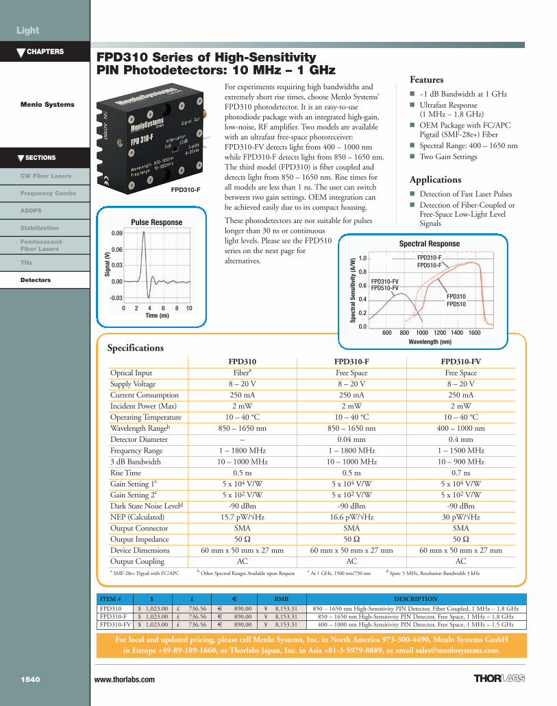
FPD310 Series of High-SensitivityPIN Photodetectors: 10 MHz – 1 GHz
Specifications
For experiments requiring high bandwidths andextremely short rise times, choose Menlo Systems’FPD310 photodetector. It is an easy-to-usephotodiode package with an integrated high-gain,low-noise, RF amplifier. Two models are availablewith an ultrafast free-space photoreceiver:FPD310-FV detects light from 400 – 1000 nmwhile FPD310-F detects light from 850 – 1650 nm.The third model (FPD310) is fiber coupled anddetects light from 850 – 1650 nm. Rise times forall models are less than 1 ns. The user can switchbetween two gain settings. OEM integration canbe achieved easily due to its compact housing.
These photodetectors are not suitable for pulseslonger than 30 ns or continuouslight levels. Please see the FPD510series on the next page foralternatives.
Spectral Response
Wavelength (nm)
Spec
tral
Sens
itivi
ty(A
/W) FPD310-F
FPD510-F
FPD310FPD510
FPD310-FVFPD510-FV
1.0
0.8
0.6
0.4
0.2
0.0600 800 1000 1200 1400 1600
Pulse Response
Time (ns)
Sign
al(V
)
0.09
0.06
0.03
0.00
-0.03
0 2 4 6 8 10
FPD310-F
Features ~1 dB Bandwidth at 1 GHz Ultrafast Response
(1 MHz – 1.8 GHz) OEM Package with FC/APC
Pigtail (SMF-28e+) Fiber Spectral Range: 400 – 1650 nm Two Gain Settings
Applications Detection of Fast Laser Pulses Detection of Fiber-Coupled or
Free-Space Low-Light LevelSignals
FPD310 FPD310-F FPD310-FVOptical Input Fibera Free Space Free SpaceSupply Voltage 8 – 20 V 8 – 20 V 8 – 20 VCurrent Consumption 250 mA 250 mA 250 mAIncident Power (Max) 2 mW 2 mW 2 mWOperating Temperature 10 – 40 °C 10 – 40 °C 10 – 40 °CWavelength Rangeb 850 – 1650 nm 850 – 1650 nm 400 – 1000 nmDetector Diameter – 0.04 mm 0.4 mmFrequency Range 1 – 1800 MHz 1 – 1800 MHz 1 – 1500 MHz3 dB Bandwidth 10 – 1000 MHz 10 – 1000 MHz 10 – 900 MHzRise Time 0.5 ns 0.5 ns 0.7 nsGain Setting 1c 5 x 10⁴ V/W 5 x 10⁴ V/W 5 x 10⁴ V/WGain Setting 2c 5 x 10² V/W 5 x 10² V/W 5 x 10² V/WDark State Noise Leveld -90 dBm -90 dBm -90 dBmNEP (Calculated) 15.7 pW/√Hz 16.6 pW/√Hz 30 pW/√HzOutput Connector SMA SMA SMAOutput Impedance 50 Ω 50 Ω 50 ΩDevice Dimensions 60 mm x 50 mm x 27 mm 60 mm x 50 mm x 27 mm 60 mm x 50 mm x 27 mmOutput Coupling AC AC ACa SMF-28e+ Pigtail with FC/APC b Other Spectral Ranges Available upon Request c At 1 GHz, 1500 nm/750 nm d Span: 5 MHz, Resolution Bandwidth 3 kHz
07_Detectors_1539-1541.qxd.P:1539-1541 7/27/11 2:50 PM Page 1540

www.thorlabs.com
CHAPTERS
Menlo Systems
SECTIONS
CW Fiber Lasers
Frequency Combs
ASOPS
Stabilization
FemtosecondFiber Lasers
THz
Detectors
Light
1541
ITEM # $ £ € RMB DESCRIPTION
FPD510 $ 1,367.80 £ 984.82 € 1.190,00 ¥ 10,901.37 850 - 1650 nm, High-Sensitivity PIN Detector, Fiber-Coupled, 0 - 250 MHzFPD510-F $ 1,367.80 £ 984.82 € 1.190,00 ¥ 10,901.37 850 - 1650 nm, High-Sensitivity PIN Detector, Free Space, 0 - 250 MHzFPD510-FV $ 1,367.80 £ 984.82 € 1.190,00 ¥ 10,901.37 400 - 1000 nm, High-Sensitivity PIN Detector, Free Space, 0 -250 MHz
Specifications
For local and updated pricing, please call Menlo Systems, Inc. in North America 973-300-4490, Menlo Systems GmbHin Europe +49-89-189-1660, or Thorlabs Japan, Inc. in Asia +81-3-5979-8889, or email [email protected].
Menlo Systems’ FPD510 series of High Sensitivity PIN Photodetectors areoptimized for the highest signal-to-noise ratio when detecting low-level optical beatsignals at frequencies up to 250 MHz. The unit is recommended, in particular, forapplications in metrology when beat signals of weak power have to be detected in ahighly efficient way. Models for both the visible and the near infrared spectralranges are available. The FPD510 photodetectors feature ultrafast fiber-coupled orfree-space photoreceivers with an integrated low-noise transimpedance amplifier.The 3 dB bandwidth of the DC-coupled device is 200 MHz. The compact designof these detectors allows for easy OEM integration.
FPD510 Series of High SensitivityPIN Photodetectors: DC – 200 MHz
FPD510-FM
Applications Detection of Chopped Light
Sources Fiber-Coupled or Free-Space Low-
Light Signals
The eye diagram is a useful tool for thequantitative analysis of signaltransmission. The excellent signal-to-noise ratio of the FPD510 detectorenables the evaluation of amplitudeand phase jitter characteristics of anoptical communication system basedon amplitude modulated pulsed lasersources with low-light optical signals.
Features High Signal-to-Noise Ratio Flat Spectral Response (Less than
3 dB up to 200 MHz) OEM Package with FC/APC
Pigtail (SMF-28e+) or Free-SpaceModule
FPD510 FPD510-F FPD510-FVOptical Input Fibera Free Space Free SpaceSupply Voltage 8 - 20 V 8 - 20 V 8 - 20 VCurrent Consumption 50 mA 50 mA 50 mAIncident Power (Max) 10 mW 10 mW 10 mWOperating Temperature 10 - 40 °C 10 - 40 °C 10 - 40 °CSpectral Rangeb 850 - 1650 nm 850 - 1650 nm 400 - 1000 nmDetector Diameter – 0.3 mm 0.4 mmFrequency Range 0 - 250 MHz 0 - 250 MHz 0 - 250 MHz3 dB Bandwidth 0 - 200 MHz 0 - 200 MHz 0 - 200 MHzRise Time 2 ns 2 ns 2 nsGainc 4 x 10⁴ V/W 4 x 10⁴ V/W 4 x 10⁴ V/WDark State Noise Leveld -120 dBm -120 dBm -120 dBmNEP (Calculated) 3 pW/√Hz 3.2 pW/√Hz 6 pW/√HzOutput Connector SMA SMA SMAOutput Impedance 50 Ω 50 Ω 50 ΩDevice Dimensions 60 mm x 50 mm x 27 mm 60 mm x 50 mm x 27 mm 60 mm x 50 mm x 27 mmOutput Coupling DC DC DCa SMF-28e+ Pigtail with FC/APC b Other Spectral Ranges Available on Request c At 200 MHz, 1500 nm/750 nm d 5 – 200 MHz, Span: 3 MHz, Resolution Bandwidth 3 KHz
07_Detectors_1539-1541.qxd.P:1539-1541 7/25/11 3:20 PM Page 1541


![Moshe Idel: Abulafia's Secrets of the Guide · Idel, «Major Currents in Italian Kabbalah between 1560-1660», Italia Judaica [Roma, 1986], II, p. 243-262; reprinted in D.B. Ruderman,](https://img.pdfslide.net/doc/110x75/612fa0b41ecc51586943923c/moshe-idel-abulafias-secrets-of-the-guide-idel-major-currents-in-italian-kabbalah.jpg)


![The Interregnum (1649-1660) The “Interregnum” Period [ 1649-1660 ] †The Commonwealth (1649-1653) †The Protectorate (1654-1660)](https://img.pdfslide.net/doc/110x75/56649e725503460f94b718c7/the-interregnum-1649-1660-the-interregnum-period-1649-1660-the.jpg)