Embed Size (px)
Citation preview

Astrometric Survey for Extra-Solar Planetswith PRIMA
Requirements on Differential AT Mirror Surface Localizations
Doc. No. VLT-TRE-AOS-15753-0004Issue 0.2.281Date October 8, 2006
Prepared Richard J. Mathar October 8, 2006Signature
Approved Denis Megevand October 8, 2006Signature
Released Didier Queloz October 8, 2006Signature

ii PRIMA: AT Mirror Definitions Issue 0.2.281 VLT-TRE-AOS-15753-0004
Change Record
Issue Date Section/Parag. affected Reason/Initiation/Documents/Remarks
0.1 07-Jul-2005 all created0.1.286 13-Oct-2005 all presented during progress meeting of Oct 140.1.348 14-Dec-2005 all updated for progress meeting of Dec 190.2.023 23-Jan-2006 Ref. [16] added0.2.185 4-Jul-2006 Ref. [17] added0.2.192 11-Jul-2006 Ref. [15] added0.2.281 8-Oct-2006 Ref. [8] added
Contents
1 Abstract 11.1 Documents . . . . . . . . . . . . . . . . . . . . . . . . . . . . . . . . . . . . . . . . . . 11.2 Acronyms . . . . . . . . . . . . . . . . . . . . . . . . . . . . . . . . . . . . . . . . . . . 2
2 Astrometric Mode 4
3 Error Budget 4
4 AT Coude Train Definition: Requirements 4
5 AT Coude Train Definition: Expected Status Quo 5
6 Approaches to Improved Sensitivities 56.1 PRIMET Extension to M2 . . . . . . . . . . . . . . . . . . . . . . . . . . . . . . . . . . 6
6.1.1 Star Separator Design . . . . . . . . . . . . . . . . . . . . . . . . . . . . . . . . 66.1.2 Common Path Definition . . . . . . . . . . . . . . . . . . . . . . . . . . . . . . 66.1.3 Polarization . . . . . . . . . . . . . . . . . . . . . . . . . . . . . . . . . . . . . . 76.1.4 Beam Expansion . . . . . . . . . . . . . . . . . . . . . . . . . . . . . . . . . . . 76.1.5 Baselines . . . . . . . . . . . . . . . . . . . . . . . . . . . . . . . . . . . . . . . 86.1.6 Miscellaneous . . . . . . . . . . . . . . . . . . . . . . . . . . . . . . . . . . . . . 8
6.2 Inverse Astrometry . . . . . . . . . . . . . . . . . . . . . . . . . . . . . . . . . . . . . . 86.2.1 Single Star . . . . . . . . . . . . . . . . . . . . . . . . . . . . . . . . . . . . . . 86.2.2 Double Star . . . . . . . . . . . . . . . . . . . . . . . . . . . . . . . . . . . . . . 9
6.3 Calibration with Axis Flips . . . . . . . . . . . . . . . . . . . . . . . . . . . . . . . . . 96.4 A Posteriori Software Filters . . . . . . . . . . . . . . . . . . . . . . . . . . . . . . . . 106.5 Pupil Diameter Reduction . . . . . . . . . . . . . . . . . . . . . . . . . . . . . . . . . . 106.6 Dedicated AT Structure Sensors . . . . . . . . . . . . . . . . . . . . . . . . . . . . . . 10
6.6.1 Another Local Laser Metrology . . . . . . . . . . . . . . . . . . . . . . . . . . . 106.6.2 Tilt Sensors . . . . . . . . . . . . . . . . . . . . . . . . . . . . . . . . . . . . . . 116.6.3 Reference Structure . . . . . . . . . . . . . . . . . . . . . . . . . . . . . . . . . 12
6.7 Star Selection . . . . . . . . . . . . . . . . . . . . . . . . . . . . . . . . . . . . . . . . . 12

PRIMA: AT Mirror Definitions Issue 0.2.281 VLT-TRE-AOS-15753-0004 iii
7 Summary 13
List of Figures
1 Statistics of WDS star separations . . . . . . . . . . . . . . . . . . . . . . . . . . . . . 13
List of Tables
1 Estimated PRIMET Polarimetry . . . . . . . . . . . . . . . . . . . . . . . . . . . . . . 7

iv PRIMA: AT Mirror Definitions Issue 0.2.281 VLT-TRE-AOS-15753-0004

PRIMA: AT Mirror Definitions Issue 0.2.281 VLT-TRE-AOS-15753-0004 1
1 Abstract
Astrometry with PRIMA/VLTI puts high requirements on the knowledge of 4-way, dual-beam dif-ferential optical path differences for off-axis beams impinging on two Auxiliary Telescopes.
At a prototypical star separation of τ = 1′, if an error in the differential OPD of 5 nm is allowed,M1, M2, and M5 must not be shifted (decentered) by more than 0.3 µm in the U -direction (awayfrom the plane of the Coude train, the case of the reference pointing), and M7 not by more than 0.15µm. Displacements of other realy optics mirrors or into other directions are less critical.
These requirements are relaxed inversely proportional to the star separation τ . On the other hand,placing the stars asymmetrically across the STS edge increases the sensitivity of the DOPD to mirrorplacement.
This document is in fulfillment of the PDR AIs #2 and #3 [4]; this is its sole purpose. It paraphrases asubset of information that is discussed in detail in [21]. Any strategy to deal with these requirementson an observational basis (“calibration”) will eventually be reformulated and moved over to theappropriate places in [18] and [7].
1.1 Documents
[1] Alenia SPAZIO 2003, Fringe Sensor Unit, Final Design Review, Tech. rep.
[2] Andolfato, L., & Karban, R. 2005, VLTI PRIMA Supervisor Software Interface Control Docu-ment. VLT-ICD-ESO-15736-3060
[3] Delabre, B. 1992, Specification for the optical layout of the VLT Auxiliary Telescopes. VLT-SPE-ESO-15100-0299
[4] Delplancke, F. 2005, Minutes of Meeting, PAOS Preliminary Design Review. TSD-05/42
[5] Glindemann, A. 2000, PRIMA, the Phase Referenced Imaging and Microarcsecond Astrometryfacility: System Description. VLT-SPE-ESO-15700-2207
[6] Karban, R., & Wirenstrand, K. 2004, AT#1 Commissioning: Pointing, Test Report. VLT-TRE-ESO-15100-3464
[7] Launhardt, R. 2005, PRIMA Astrometry Calibration and Operation Plan. VLT-PLA-AOS-15759-0001
[8] Leveque, S. 2000, in Interferometry in Optical Astronomy, edited by P. J. Lena, & A. Quirren-bach (Int. Soc. Optical Engineering), vol. 4006 of Proc. SPIE, 388
[9] Leveque, S., Salvade, Y., Wilhelm, R., & Rabeling, D. 2002, PRIMA Metrology Test Campaign27/4/02 to 5/5/02. VLT-TRE-ESO-15730-2827

2 PRIMA: AT Mirror Definitions Issue 0.2.281 VLT-TRE-AOS-15753-0004
[10] Mathar, R. J. 2005, Astrometric Survey for Extra-Solar Planets with PRIMA, Requirementson Medium-Term Stability of Air Parameters in VLTI Ducts and Delay Lines. VLT-SPE-AOS-15753-0003
[11] Menardi, S., & Gennai, A. 2001, Technical Specification for the PRIMA Fringe sensor unit.VLT-SPE-ESO-15740-2210
[12] Murakawa, K., & Mathar, R. J. 2005, Astrometric Survey for Extra-Solar Planets with PRIMA,Polarization Effects. AS-TRE-AOS-15753-0011
[13] Nijenhuis, J. R. 2003, PRIMA Star Separater (STS), Design and Analysis Report. VLT-TRE-TNO-15710-0001
[14] Pirnay, O. 2002, VLT The Auxiliary Telescope System, Telescope Structural Deflection TestReport. VLT-TRE-AMO-151100-265
[15] Porro, I. L. 1997, Ph.D. thesis, University of Padova. http://cisas.unipd.it/STS course/thesis/tesi IP.pdf
[16] Reffert, S. 2005, PRIMA astrometric standard stars
[17] Reffert, S., Launhardt, R., Heeker, S., Henning, T., Queloz, D., Quirrenbach, A., Segransan,D., & Setiawan, J. 2005, in Astrometry in the Age of the Next Generation of Large Telescopes,edited by P. K. Seidelmann, & A. K. B. Monet (Astron. Soc. Pacific), vol. 338 of ASP Conf. Ser.,81. http://www.aspbooks.org/custom/publications/table of contents/?book id=48
[18] Reffert, S., Quirrenbach, A., Jaffe, W. J., & Mathar, R. J. 2005, Astrometric Survey for Extra-Solar Planets with PRIMA, Operation and Calibration Strategy. VLT-TRE-AOS-15754-0001
[19] Shao, M., & Colavita, M. M. 1992, Astron. Astrophys., 262, 353
[20] Stanghellini, S., & Michel, A. 1998, The Messenger, 94, 10
[21] Tubbs, R. N., & Mathar, R. J. 2006, Astrometric Survey for Extra-Solar Planets with PRIMA,Astrometric Error Budget. VLT-TRE-AOS-15753-0001
1.2 Acronyms
AI Action Item
AMOS Advanced Mechanical and Optical Systems http://www.amos.be/index.htm
ARC Ecole d’ingenieurs de l’arc Jurassie http://www.eiaj.ch/
ASTRON Stichting Astronomisch Onderzoek in Nederland http://www.astron.nl
AT Auxiliary Telescope (of the VLTI)http://www.eso.org/projects/vlti/AT/index at.html
DAF Data Analysis Facility http://www.strw.leidenuniv.nl/~nevec/PRIMA/
DOPD differential OPD

PRIMA: AT Mirror Definitions Issue 0.2.281 VLT-TRE-AOS-15753-0004 3
DRS Data Reduction System
EPFL Ecole Polytechnique Federale de Lausanne http://www.epfl.ch
ESO European Southern Observatory http://www.eso.org
FEM Finite Element Method
FOV field of view
FSM Field Selector Mirror (of the STS)
FSU Fringe Sensing Unit
GIS Ground Interface Structure
ICS Instrument Control Software
IOTA Infrared Optical Telescope Array http://www.cfa.harvard.edu/cfa/oir/IOTA/
IRIS Infrared Image Sensor http://www.eso.org/projects/vlti/iris/
ISS Interferometric Supervisor-Software
MIDI Mid-Infrared Interferometric Instrument http://www.mpia.de/MIDI
MPIA Max-Planck Institut fur Astronomie, Heidelberg http://www.mpia.de
NOVA Nederlandse Onderzoekschool voor Astronomiehttp://www.strw.leidenuniv.nl/nova/
OPD optical path difference
OPL optical path length
PDR Preliminary Design Review
PRIMA Phase-Reference Imaging and Microarcsecond Astrometryhttp://obswww.unige.ch/Instruments/PRIMA
PRIMET PRIMA Metrologyhttp://www.eso.org/projects/vlti/instru/prima/description lms prima.html
PS primary star
ROS Relay Optics Structure
SS secondary star
STRAP System for Tip-tilt removal with Avalanche Photodiodes
STS star separator
UT Unit Telescope (of the VLTI) http://www.eso.org/projects/vlt/unit-tel/
VIS visible (part of the electromagnetic spectrum)
VLTI Very Large Telescope Interferometer http://www.eso.org/vlti
WDS Washington Double Star (Catalog) http://ad.usno.navy.mil/wds/
4 PRIMA: AT Mirror Definitions Issue 0.2.281 VLT-TRE-AOS-15753-0004
2 Astrometric Mode
The dual-beam interferometer PRIMA at the VLTI aims at µas accuracy for the differential opticalpath difference DOPD between the two beams (two stars/sources). Standard trigonometry for tem-plate baselines of ≈ 100 m translates this to requirements on the accuracy of the delay differencebetween the two interferometers represented by both beams of typically ≈ 5 nm [5]. 1
3 Error Budget
In rough terms, PRIMA interferometry measures a grand total phase of the wave packet by the FSUs.The difference between these is attributed to the “external” phase representing positions on the sky.As the AT mirrors M1–M8 (the de-rotator inclusive) are not monitored by PRIMET, any unforeseen(unknown) asymmetry in the optical path length of any of the two beams between the two telescopesbecomes a signal sensed by the corresponding FSU, which is indistinguishable from and potentiallymisinterpreted as a signal originating from a modification in stellar position.2
In a straight forward manner this leads to the request that the OPL of the beam between somereference point on M1 of AT1 up to the M11/FSM of the STS and the OPL of the equivalent beambetween the equivalent reference point on M1 of AT2 up to the other M11/FSM of the STS do notdiffer by more than ≈ 5 nm for off-axis angles up to an isoplanatic angle (star separation) of ≈ 20′′.3.
If the asymmetry between the telescopes causes larger systematic deviations than 5 nm, the actualasymmetry must be made available to the DRS for off-line correction, typically via explicit single-shotonline measurements of auxiliary parameters, measurements of the chopping/nodding/beam-swaptype that have intrinsic capabilities of error subtraction, or measurements of the calibration typethat assume stability of some opto-mechanical model.
4 AT Coude Train Definition: Requirements
The sensitivity of the OPL to mirror translations and rotations depends on the off-axis angle, thetelescope pointing direction, and the mirror (position, orientation, conic constants). Assuming thatthe two M11/FSM remove the static tip and tilt that may be left from these distortions, 5 nm ofDOPD are equivalent to motions of the magnitude of 0.2 µm of M1, M2, M5 or M7 at a star separationof τ = 1′, with requirements relaxed ∝ τ at smaller separations.4 This refers to the non-zero mean ofthe difference between both ATs averaged over the same time scale that is attached to the goal of 5nm in DOPD, not to the vibrations of the structure.5 The requirement is to know the “zero-sound”static difference between the bending of the two telescope structures and their mirror mounts tobetter than 0.2 µm for these particular optical surfaces. The requirements on the knowledge of axistilts are typically 0.1′′ for M2–M5, 0.01′′ for M1 and M7–M8.6
1This transformation is detailed in Section 28.3.2 of [21], and not reviewed here.2 This is discussed in Section 11.4.2 of [21].3See Section 26.3.3 of [21]. The value of this angle is not a subject of this memorandum, and it is to be regarded as
a representative but not an exact value.4This is the summary of Section 13.4 of [21] and may be compared with the requirements estimated for IOTA [15,
§3.5.4]5See Sect. 22.3 in [21].6This is a summary of the 1′ star separation columns in Table 5 in [21].
PRIMA: AT Mirror Definitions Issue 0.2.281 VLT-TRE-AOS-15753-0004 5
The answer to the question in how far the expected alignment of the relay and Coude trains meetsthe requirements depends strongly on (i) which mirror is considered, (ii) which of the six parameters(rotational, translational) of this mirror, (iii) the star separation angle τ , and the split ratio of τ overthe two faces of the M10/STS edge, (iv) the alignment of the field rotation as selected by the STSwith the stiffer direction defined by the horizontal telescope axis, (v) the action of IRIS on M11/FSMas the common parameter set on both interferometric telescopes, plus a further set of parameterswhich generate differences in the mirror geometry between both telescopes. All these parametersplay also roles in other aspects of the error budget [21] and [12]; to avoid an editorial nightmare wedo not copy the various parameters, tables, discussions from the error budget to this document.
5 AT Coude Train Definition: Expected Status Quo
The PRIMA consortium did neither specify the accuracy of the optical train, nor did it build the ATsnor did it perform any tests on the available telescopes: Theoretical and rather implicit estimateson the actual performance/compliance of the forefront optics are drawn from available AMOS testreports in Section 13.5 of [21].
In summary of the corresponding part in the error budget, the most violent apparent problem (inthe sense that any of the aforementioned measurements allows to reduce data to the differentialOPD) is a differential (in the sense of unpredictable) tilt of M1 along one optical axis—defined asthe non-reproducible misalignment with the M2 axis—which may induce a DOPD 30 times largerthan the 5 nm aim, at a star separation of τ = 20′′. Combined with a contribution of 8 times theerror budget of 5 nm from M2, this is roughly 40 times the allowance, and would grow by anotherfactor of three if τ = 1′.
Axis runouts and over/undershooting of the altitude and azimuth axes will probably introduce awiggle with a simple cosine-dependence on the azimuth direction in the narrow-angle baseline, at anamplitude of about the allocated prototypical error of 50 µm.7 Compared to the compliance withthe need for an accurate measurement of the DOPD this is a minor problem and not discussed anyfurther. The axis runout contribution to the DOPD is estimated at less than 30 nm.8
6 Approaches to Improved Sensitivities
At this point, the Consortium is extending its task of providing an error budget for the instrumentas being build by ESO and takes the role of a consultant to improve on the technology involved.
Subsequent mentioning of resources to gather precise information to meet the PRIMA criteria onthe path length control does not indicate that any of these methods is recommended or endorsed bythe consortium or the author, or that these means are a complete set of all options. The PRIMETextension is studied to fulfill AI#3 of [4]. Dead-end ideas like the one mentioned in Sect. 6.5 areincluded as well.
The author is not aware of any study of this problem beyond [9], which we therefore discuss first inSect. 6.1. The baseline is always measurement, rather than active control, of the de-facto locationof mirror surfaces. This may result in a direct output as a differential OPD, or in auxiliary surface
7 Section 11.4.3 of [21].8Section 13.5.5 of [21].
6 PRIMA: AT Mirror Definitions Issue 0.2.281 VLT-TRE-AOS-15753-0004
coordinates that need an additional synthetic beam model as the one used to derive all of the effectsin the current error analysis.
6.1 PRIMET Extension to M2
Let us consider the idea to separate the differential delay caused by the mirror motions as describedabove from the differential delay caused by the star separation by measuring the mirror motionsexplicitly. The option of moving the PRIMET point of return such that the laser touches also thesemirror surfaces comes obviously into mind [8].
The impact on PRIMET is considered supposed the laser point of return is moved from RR3 in theSTS to the “blind spot” in the M2 center, adding a new retro-reflector there which we shall call M2R.The questions are (i) In how far would the two paths of the laser still represent the path lengths ofthe “science” light? (ii) Would the laser light suffer from back-coupling efficiencies associated withvariable polarization as a function of pointing? (iii) Would the laser light suffer from a strong lateralexpansion, which might reduce coupling efficiency and/or lead to spilling of the waist beyond thecentral core of the beams that match the FSU dichroics? (iv) Will the STS design be violated? (v)Is the formal decoupling from the narrow-angle baseline definition important?
6.1.1 Star Separator Design
If one wants to move the laser retro-reflector further up in the mirror train, the laser light is to bereflected from M9, whereas the current design [13] defines the laser path by the transmitted light.
• One can leave the mirrors RR1–RR3 in the ROS in place if somewhere between these a highlyabsorptive screen is added which attenuates this part of the 1.3 µm signal to avoid cross-talkwith the laser light returning from the new M2R.
• The M9 dichroics would have to be changed from optimizing transmission at 1.3 µm to opti-mizing reflectance.
6.1.2 Common Path Definition
To image M10 on itself, M2R must be convex with a radius of curvature of ≈ 3.8 m.9 This could onlybe achieved with a path length precision better than 100 µm if M2R also becomes a roof top mirrorof two parts that intersect at an angle of ≈ 174◦, each matching one corresponding section of thesplit M10. This complicates the design because this ridge on M2R would have to be aligned with themotorized star rotator angle.10 This need of moving also the PRIMET end point is disadvantageouscompared to the current design where RR1–RR3 are fixed.
Note that, although the PRIMET diameter is only a fraction of the science beam diameter, this doesnot mean that the laser beam becomes very insensitive to the tilts by the ∝ τ scaling of the DOPD:11
The two PRIMET branches would trace the core of their associated science beams up to M2R andbe fully sensitive to the first order of the effect. This is obviously what raises the need to model theM2R with two sections.
9This copies the role of the current RR3. The estimate is from Gaussian Optics assuming M3, M4, M6 and M8 areflat, and means the existing Nasmyth focus between M4 and M5 is one radius away from M2R.
10 Other reflector solutions than this have not been investigated.11See of Table 5 of [21].
PRIMA: AT Mirror Definitions Issue 0.2.281 VLT-TRE-AOS-15753-0004 7
Fig. 34 of [21] demonstrates that there is a structure in the OPL across the wave front for starseparations of τ ≥ 30′′ that is inherent to the AT and STS optics: For larger star separations,probing the optical path with PRIMET only at the beam center is no longer equivalent to buildingsome “mean” as implemented by the FSU fiber hardware.
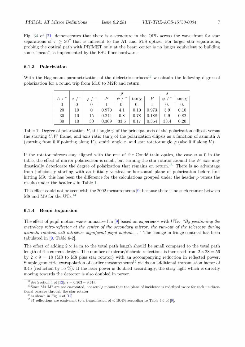
6.1.3 Polarization
With the Hagemann parametrization of the dielectric surfaces12 we obtain the following degree ofpolarization for a round trip from M10 to M2R and return:
p sA / ◦ z / ◦ ϕ / ◦ P ψ / ◦ tanχ P ψ / ◦ tanχ
0 0 0 1 0. 0. 1 0. 0.20 10 0 0.970 4.1 0.10 0.973 3.9 0.1030 10 15 0.244 0.8 0.78 0.188 9.9 0.8230 10 30 0.369 33.5 0.17 0.364 33.4 0.20
Table 1: Degree of polarization P , tilt angle ψ of the principal axis of the polarization ellipsis versusthe starting U,W frame, and axis ratio tanχ of the polarization ellipsis as a function of azimuth A(starting from 0 if pointing along V ), zenith angle z, and star rotator angle ϕ (also 0 if along V ).
If the rotator mirrors stay aligned with the rest of the Coude train optics, the case ϕ = 0 in thetable, the effect of mirror polarization is small, but turning the star rotator around the W axis maydrastically deteriorate the degree of polarization that remains on return.13 There is no advantagefrom judiciously starting with an initially vertical or horizontal plane of polarization before firsthitting M9: this has been the difference for the calculations grouped under the header p versus theresults under the header s in Table 1.
This effect could not be seen with the 2002 measurements [9] because there is no such rotator betweenM8 and M9 for the UTs.14
6.1.4 Beam Expansion
The effect of pupil motion was summarized in [9] based on experience with UTs: “By positioning themetrology retro-reflector at the center of the secondary mirror, the run-out of the telescope duringazimuth rotation will introduce significant pupil motion. . . ” The change in fringe contrast has beentabulated in [9, Table 6-2].
The effect of adding 2 × 14 m to the total path length should be small compared to the total pathlength of the current design. The number of mirror/dichroic reflections is increased from 2× 28 = 56by 2 × 9 = 18 (M3 to M8 plus star rotator) with an accompanying reduction in reflected power.Simple geometric extrapolation of earlier measurements15 yields an additional transmission factor of0.45 (reduction by 55 %). If the laser power is doubled accordingly, the stray light which is directlymoving towards the detector is also doubled in power.
12See Section 4 of [12]: ε = 0.303− 9.61i.13Since M4–M7 are not co-rotated, nonzero ϕ means that the plane of incidence is redefined twice for each unidirec-
tional passage through the star rotator.14as shown in Fig. 4 of [12]1537 reflections are equivalent to a transmission of < 19.4% according to Table 4.6 of [9].
8 PRIMA: AT Mirror Definitions Issue 0.2.281 VLT-TRE-AOS-15753-0004
The ratio of the laser over the beam diameter is 2.5 mm / 18 mm ≈ 0.14 at the FSU.16 Up-conversionto the M2 diameter of 0.138 m [3] yields an estimated laser beam diameter of 19 mm on M2R. Weexpect the central hole17 in M2 to match the ratio of M2/M1, ie, to have a diameter of 0.138·0.138/1.8m≈ 10.5 mm. This would introduce a severe clipping of the laser beam, cutting the power returnedby a factor (1.05/1.9)2 ≈ 0.30—the rest being lost into the night sky via M1. To avoid this, thePRIMET beam would have to be confined to a diameter of ≈ 1.3 mm at the FSU. In consequence,the pupil motions up to 0.3 mm reported with the 11 mm test beam [9] will become even moreimportant to the variation of the overlap.
6.1.5 Baselines
The narrow-angle baseline is fixed by the centers of the four M11/FSM involved. It is relocatable,which means that the three components of the vector can be translated to another place.18 Forexample, it could as well be defined by the images of these mirrors if the Coude train would besubstituted by one effective mirror. In summary, using PRIMET also as a monitor of baselinechanges is not effected by moving its point of return from RR3 to M2.
6.1.6 Miscellaneous
It is clear that this type of reaching with PRIMET to M2 could only gather information on two outof four “critical” mirrors, M5 and M7 but not M1 and M2.19
MIDI chops with M6 at up to 5 Hz. The extended PRIMET may run into problems if used for animaging mode in this scenario because all M6 vibrations are imprinted on the laser beam.20
6.2 Inverse Astrometry
6.2.1 Single Star
Are there any chances of mapping the OPL as a function of off-axis angle by moving the maintelescope axis away from a single star with some kind of open-loop of STRAP and IRIS such that(one detector of) the FSU can build an OPL map as a function of off-axis angle? The signature ofthe (now non-differential) effect is a quadratic function of the off-axis angle.21 One might envisage asingle-star calibration mode—fundamentally different from the STS “split” mode—where the samestar is judiciously placed on “opposite” sides of the two STSs of the two telescopes with varyingdistance to the main telescope axis, which would allow to find the center of this quadratic functionin an off-line retro-fit.
The problems with this type of approach are
• Software: the ISS has no (public) mode of operation to run the telescopes in cross-eyed pointing.16taken from [11, §3.4.26.3] and compatible with the mention of the factor 0.15 in [1].17The author does not have information on whether the ATs have indeed an opening as do the UTs [20, Table 1]
which would allow additional optics be placed on the rear-side of M2. At a diameter of 13 cm and the rear interfacedisplayed in [14, Fig 4-2]—crowded with the focussing opto-mechanics—this seems unlikely.
18See Section 11.2.2 of [21]. This ignores small parallactic effects.19see Table 5 in [21].20Since the throw is of the order of 10′′, the metrology would stay on M2R without being nominally interrupted.21Figure 29 in [21]
PRIMA: AT Mirror Definitions Issue 0.2.281 VLT-TRE-AOS-15753-0004 9
• Hardware: to map the two off-axis images of the same star in both telescopes on the sameFSU for interferometry, the star rotator must rotate the FOV in one telescope by 180◦ (thestar rotator axis rotate by 90◦), which introduces a new potential source of error in form ofimperfection of the rotator operation.
6.2.2 Double Star
A calibration method is to use the three fundamental variables (star separation vector projected onthe projected baseline, differential OPD, baseline length) to calibrate each of them independentlyor in combination with astrometry on well-known objects. The major problem when applied tothe mapping of the DOPD is that there are many other error sources in the Error Budget withsimilar signature (dependence on star separation, telescope pointing direction. . . ) which are unlikelyseparable from the contribution of asymmetric telescope optics as discussed here.22
In a—definitely more complicated—double source version of the method of Section 6.2.1, one may usethe predicted uniaxial dependence predicted by the theory, and the axis mixing introduced by placingthe two stars not symmetrically across the STS edge23 to build a 2D map of the off-axis positions as afunction of edge distance and (deliberately tweaked) star rotator angle. The philosophy behind sucha search for the “true zero” of the DOPD is that any error in the optical train can be transformed to acalibration method once there are controlled parameters (here: star placements within the 2D FOV)and a solid theoretical model (here: the ray tracing proposals) which can be joined. The intrinsicgeneric problem is whether the degrees of freedom in the controlled parameters (that would be fourfor both 2D maps if both telescopes are operated individually, using one fixed binary) is sufficient tocover the number of free parameters in the model (that would in some sense be only one, the leakyDOPD).
6.3 Calibration with Axis Flips
An experimental assessment of the OPD error associated with the non-ideal telescope structurecould be attempted by using two equivalent telescope positions in succession for a single nominalstar position: ideally, one can reach to a single sky position by rotating the azimuth axis by 180◦ andflipping over the altitude axis to the opposite side. In a pre-PRIMA test setup, with instruments likeVINCI or even MIDI, piston differences on the 1 µm level (?) might be detectable (if this axis flipis done faster than the piston inherited from tunnel water vapor wandering [10]), although absenceof the effect in the PRIMA error budget could not be proved because this still is 200 times coarserthan the target of 5 nm.
During the regular operation, one may think in principle of successive axis flips on both telescopes togenerate a “calibration” of the differential piston, building some poor statistical average across thefour data points that emerge. The disadvantage of this type of operation might be that the telescopeaxis is forced through the zenith point which is worst affected by axis run-outs and de-centeredmirrors.24 However, if this is the method to re-settle axis bearings and mirror contacts, this way ofaveraging could be useful.
As a side benefit, this type of averaging could also eliminate to first order the (unimportant) effect22to add a positive note here, this would provide a nice use case for the DAF.23noted by the numbers in parenthesis in Table 5 in [21]24see the references collected in Sect. 13.5 of [21]
10 PRIMA: AT Mirror Definitions Issue 0.2.281 VLT-TRE-AOS-15753-0004
of mutual over/undershooting of the two telescope axes.25
It is not known to the author whether some simple reasons in form of bolts or what is dubbed “cablingproblems” disallow this kind of Alt-Az coordinate swap with the ATs.26 The time overhead for thisoperation would be large (but within the 3 minutes specification for a completely new acquisition [6,§7.2]), since the flipped angular azimuth coordinate is far away from its value before the flip.
6.4 A Posteriori Software Filters
An “internal calibration” method to subtract the effect—comparable to the beam swap that ex-changes beam paths after the star rotator—is not known. Methods like waiting until the siderealmotion has rotated the vector between the two stars by 180◦ and toggled the sign of the DOPD arelikely to fail due to the long time intervals between such pairs of measurements: some phases of theDOPD are unavailable because the OPD is periodically switched off by the horizon and because bothvalues are phase coupled.27 With reference to [2, p 6] which argues “Swap objects: In Astrometricmode the primary and secondary objects can be swapped in order to identify the bias introduced bythe instrument” we see that we actually cannot swap the objects, but have to wait until they’ve beenswapped with a period close to 24 hours. Using the Earth rotation to swap the beams to eliminatethe effect puts additional constraints on scheduling and is not promising since there is hardly anycontrol on the alignment of the pair orientation with the (projected) baseline.
6.5 Pupil Diameter Reduction
Downsizing the effective M1 diameter with a mask to less than 1.82 m (or for simplicity an equivalentmask on a smaller mirror later on) has no effect on the induced “leaky” differential OPDs listed inTable 5 of [21], and does not help. The cause for this insensitivity is obvious from Figures 31 and 32of [21]: the jitter in DOPD from mirror translations and tilts is a product of distances (focal lengths),per-beam off-axis angles (star separation) and mirror curvatures, all of which do not depend on thetwo beam’s diameters.
6.6 Dedicated AT Structure Sensors
6.6.1 Another Local Laser Metrology
In principle, a further laser metrology system launched from somewhere within the GIS or ROS andreflected off the mirrors of the relay optics could serve the same purpose as the PRIMET extensionof Sect. 6.1. The advantages are
• The freedom of choice of optical paths is larger. One could stay on the “rim” of the FOV fora particular launch point to increase sensitivity, and even chose an open loop path throughthe mirrors to avoid adding more dichroics to the path of the science beam. Supposed a FEMmodel of the structure is available, one could also perform a round trip through an additionalset of flat mirrors attached to “pivot” points (Sect. 6.6.3) outside the standard beam diameter.
25Section 11.4.3 in [21].26Although not documented, one might interpret the labels “+Alt” and “-Alt” found in many figures of [14] as if this
two-sided sweep was a standard for the AT#3 tests.27see Figure 45 of [21]

PRIMA: AT Mirror Definitions Issue 0.2.281 VLT-TRE-AOS-15753-0004 11
This may turn out to be a rather optimistic point of view, however, only applicable if thesystem is restricted to monitor M1–M4. The mirror train is generally not oversized to reachdown to M7 or M8 by following any other path but the main axis within the standard FOV.
and the disadvantages
• Acquisition data rates (“stress” on the ICS) increases.
• Rather than being stationary, this system must be relocatable with the ATs, which may callfor additional calibration.
• This type of ranging delivers total/integrated path lengths, one per mirror configuration, butdoes not take into account the different criticality of the six parameters of the mirror positions.This means one point on one of the mirror surfaces visited may potentially approach the lasersource and another move away at the same time, and both “errors” may cancel to any degreein the laser interferometer’s output.
The PRIMET extension of Section 6.1 delivers a differential OPD in the PRIMA sense inhardware, whereas standard laser ranging needs to be backed up by a reduction software (similarto the dedicated C++ program and classes written by the author to generate the PRIMA errorbudget as summarized here).
• The path length being rather short, dispersion effects might be unimportant and a rangingwith some more standard frequency in the VIS might suffice. For a beam path of < 30 m andan accuracy of ≈ 200 nm one needs the index of refraction accurate to ≈ 7 · 10−9.
6.6.2 Tilt Sensors
Open questions:
• Would these provide the accuracy needed for a full range of pointing directions28
• Would these allow for any remote readout by electronics? Are there cabling problems?
• Would these find free spots on the mirror rears—with the disadvantage on adding weight tothese—or need to be measuring the mounts only?
Disadvantages:
• Some tilt sensors refer to a local coordinate system, which means they do not measure thetranslational degrees of freedom that play an equally important role in producing DOPD.Others, like those that are capacitance based, provide a “mean distance” which mixes thedirectional dependencies. Generally speaking, both “tip” and “tilt,” defined relative to thecurrent alt-az-direction, are of comparable interest. A tilt sensor may measure only a singleangle relative to the local direction of gravity, depending on the principle of measurement.
Advantages:28Off the shelf electrolytic tilt sensors would reach resolutions of 1′′ in the narrow range of a few degrees, and 4′′
over a range of 60◦, the former probably applicable to the static mirrors following M4, the later to M1–M3. This is notin any way a quote of the performances of the industry in this field, but meant to be compared with the numbers inSection 4. The author has not done a market review on this theme.

12 PRIMA: AT Mirror Definitions Issue 0.2.281 VLT-TRE-AOS-15753-0004
• Each point with a sensor attached is an independent input. This scaling is advantageous com-pared to the laser method of Section 6.6.1 which may be reflecting off an arbitrary number ofsurfaces and still yield one single path length. It might be possible to generate the “tip” infor-mation called missing in the previous bullet by some kind of subtraction of sensor distributedover the M1 surface. This, however, is a very ill-conditioned data reduction problem, and wouldonly work for the big M1 to some degree, but unlikely for M7.
Accelerometers are a problematic option, and rather complementary to the query for a stable quasi-static definition of points in space. They would need additional calibration to define the referencepoint by some other auxiliary method each time after switch-off, and then yield the distance afterdouble integration over the time elapsed since then. The absolute measure of the coordinate iscontinuously deteriorating due to linear accumulation of the internal errors over time.
6.6.3 Reference Structure
In combination with any kind of local measurement system like those mentioned above, a referencestructure is either a cage that moves with the azimuth axis or a lever that moves with both axes butnot attached to the telescope structure. The idea is to provide a mechanical reference frame thatis stiffer and less vulnerable to wind and gravity than the system carrying M1 and M2. To have itrotating with one or two telescope axes is not a key principle but allows to fix the “gauges” (planeauxiliary mirrors for an optical system or the tilt meters that measure capacitance) to them suchthat the “center-of-mass” motion of the entire system—in which we are not interested—is alreadyeliminated. An example of this principle is found with the measurements of the M1 motion relativeto the tube with inductive sensors in [14].
The generic problem is that high stiffness and lean structure (wind cross section) are in essenceopposite requirements. An additional request for low amplitudes in the frequency spectrum wouldnot have priority; an accurate mean on slow timescales by “integrating” over vibrations would sufficehere. The additional intrinsic problem is that this structure has the same expansion properties withtemperature gradients as the telescope itself (unless built from some sort of carbon enforced plastic).
6.7 Star Selection
The sensitivity of the induced DOPD error proportional to the star separation means the sensitivityto mirror displacements is ten times smaller if the star separation is reduced from 1′ to 6′′, forexample. The knife edge effect sets a lower limit of ≈ 1′′ to the star separation for the ATs, see Sect.6 of [21]. The problem can therefore be reduced but not be eliminated by selection of arbitrarilytight pairs of PS and SS.
This does not necessarily hamper the astrometric program given the skewed statistics of Figure 1.Supposed that an ample set of phase reference stars is available [16, 17][19, Fig. 5], one can roughlyloose an additional factor of two (or even more) in sensitivity to the differential M1 tilt if the star pairorientation can be chosen “along” the more stable axis which would be a function of the azimuth;the star rotator then can select a favorable field angle such that the STS edge sees two fields thatare more likely to be displaced along the STS edge than perpendicular to it.

PRIMA: AT Mirror Definitions Issue 0.2.281 VLT-TRE-AOS-15753-0004 13
100
1000
0 20 40 60 80 100 120
WDS
cou
nts
separation τ (arcsec)
A<10 magA,B<10 mag
Figure 1: A bulk statistics on the star separations listed in the WDS Catalog over all 40,400 pairswith magnitude of the primary 10 or brighter (solid), or over all 13,300 pairs with both magnitudes10 or brigher (dashed), in the PRIMA FOV of 2′. Note that “bulk” refers to the fact that there hasbeen no selection from any astronomical qualitative point of view. For comparison: the full solidangle of 4π is 47 · 106 times as large as a FOV of 2′ in diameter.
7 Summary
The most critical positioning with respect to the differential OPD is M7 which must not move outof the Coude plane by more than 380 nm to induce less than 5 nm in DOPD for a star separationof 20′′. The other powered optics (M1, M2, M5) is about half as sensitive. Requirements on thepointing (axis alignment) of M1 and M7 are ∼ 30 mas for the same goal.
The static differential piston between the two ATs could be fourty times higher than required by the5 nm specification of the DOPD at a star separation of 20′′, or 100 hundred times higher at a starseparation of 1′.
Some important aspects of extending the metrology point of return close to M2 have been pointedout during the 2002 tests. They are therefore well known to ESO and there is no good sense inparaphrasing them here. Passing twice by the star rotator is estimated to have a strong de-polarizingeffect on the PRIMET beam. This may or may not be important depending on whether the PRIMETpolarization is chosen to be linear or circular.