Embed Size (px)
Citation preview
AC
Ka
b
c
a
ARAA
KGILC
1
ctrcftrt(fl
rG
0d
Geothermics 41 (2012) 30– 54
Contents lists available at SciVerse ScienceDirect
Geothermics
j o ur nal homep age : www.elsev ier .com/ locate /geothermics
survey of the induced seismic responses to fluid injection in geothermal andO2 reservoirs in Europe
eith F. Evansa,∗, Alba Zapponeb, Toni Kraftb, Nicolas Deichmannb, Fabio Moiac
Engineering Geology, Swiss Federal Institute of Technology (ETH), Sonneggstrasse 5, 8092 Zürich, SwitzerlandSwiss Seismological Service, Sonneggstrasse 5, 8092 Zürich, SwitzerlandRSE-Ricerca Sistema Energetico S.p.A., Milan, Italy
r t i c l e i n f o
rticle history:eceived 17 February 2010ccepted 13 August 2011vailable online 21 October 2011
eywords:eothermal
njection-induced seismicityarge-magnitude events (LME)O2 sequestration
a b s t r a c t
The paper documents 41 European case histories that describe the seismogenic response of crystallineand sedimentary rocks to fluid injection. It is part of an on-going study to identify factors that havea bearing on the seismic hazard associated with fluid injection. The data generally support the viewthat injection in sedimentary rocks tends to be less seismogenic than in crystalline rocks. In both cases,the presence of faults near the wells that allow pressures to penetrate significant distances verticallyand laterally can be expected to increase the risk of producing felt events. All cases of injection intocrystalline rocks produce seismic events, albeit usually of non-damaging magnitudes, and all crystallinerock masses were found to be critically stressed, regardless of the strength of their seismogenic responsesto injection. Thus, these data suggest that criticality of stress, whilst a necessary condition for producingearthquakes that would disturb (or be felt by) the local population, is not a sufficient condition. Thedata considered here are not fully consistent with the concept that injection into deeper crystallineformations tends to produce larger magnitude events. The data are too few to evaluate the combined
effect of depth and injected fluid volume on the size of the largest events. Injection at sites with lownatural seismicity, defined by the expectation that the local peak ground acceleration has less than a 10%chance of exceeding 0.07 g in 50 years, has not produced felt events. Although the database is limited,this suggests that low natural seismicity, corresponding to hazard levels at or below 0.07 g, may be auseful indicator of a low propensity for fluid injection to produce felt or damaging events. However,higher values do not necessarily imply a high propensity.. Introduction
Induced seismicity is recognised as a possible hazard in practi-ally all engineering endeavours where stress or pore pressure inhe subsurface is altered. This can be taken as a reflection of theealization that has dawned in the past 20 years that the Earth’srust generally supports high shear stress levels and is often close toailure. Historically, the most damaging events, which have some-imes caused fatalities, are associated with the impoundment ofeservoirs (Gupta, 1992). However, earthquakes of a size sufficiento cause damage have also been associated with mining activityGibowicz, 1990), long-term fluid withdrawal (Segall, 1989) anduid injection (Nicholson and Wesson, 1990).
Given that massive fluid injections to stimulate crystallineocks have routinely been performed during Engineered/Enhancedeothermal System (EGS) projects – formerly called Hot Dry Rock
∗ Corresponding author. Tel.: +41 44 633 2521; fax: +41 44 633 1108.E-mail address: [email protected] (K.F. Evans).
375-6505/$ – see front matter © 2011 Elsevier Ltd. All rights reserved.oi:10.1016/j.geothermics.2011.08.002
© 2011 Elsevier Ltd. All rights reserved.
(HDR) projects – since the early 1970s, it is perhaps surprisingthat the issue of seismic hazard associated with these operationshas only recently come to the fore. This is because the pioneer-ing EGS developments at Fenton Hill (USA), Rosemanowes (UK),Hijiori (Japan) and Soultz (France) (3.5 km reservoir) did not pro-duce events large enough to disturb the local population, whereasmore recent attempts to develop systems at 4.5–5.0 km depth atSoultz, Cooper Basin (Australia) and Basel (Switzerland) producedevents approaching or exceeding magnitude 3. There are also oneor two instances where small but felt events have been associatedwith the operation of deep (∼3 km) hydrothermal systems.
The recent increase of interest in developing deep geothermalsystems and of sequestering large quantities of CO2 undergroundmakes it desirable to identify factors that influence the differentseismogenic responses to fluid injection at various sites. This paperdocuments the first stage of an on-going study that seeks to deter-
mine such factors through examination of incidences where fluidinjection has taken place without generating seismic events thatwere felt by the local population, as well as cases where it has. Wemake no distinction between induced and triggered seismicity.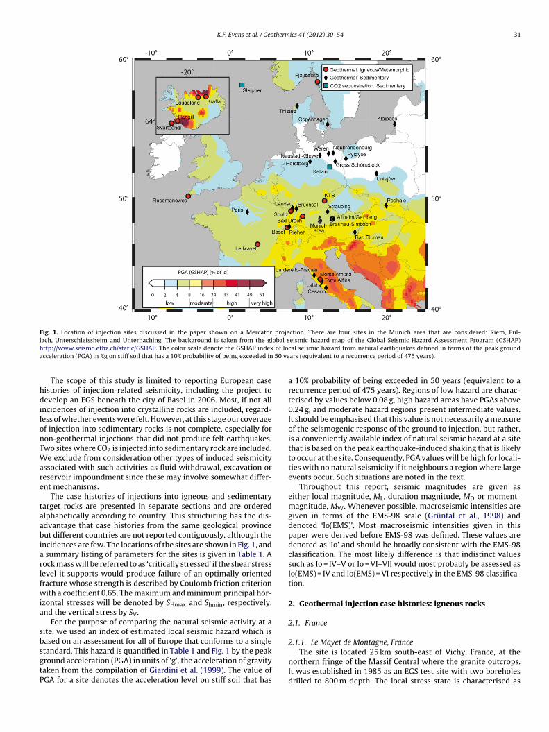
K.F. Evans et al. / Geothermics 41 (2012) 30– 54 31
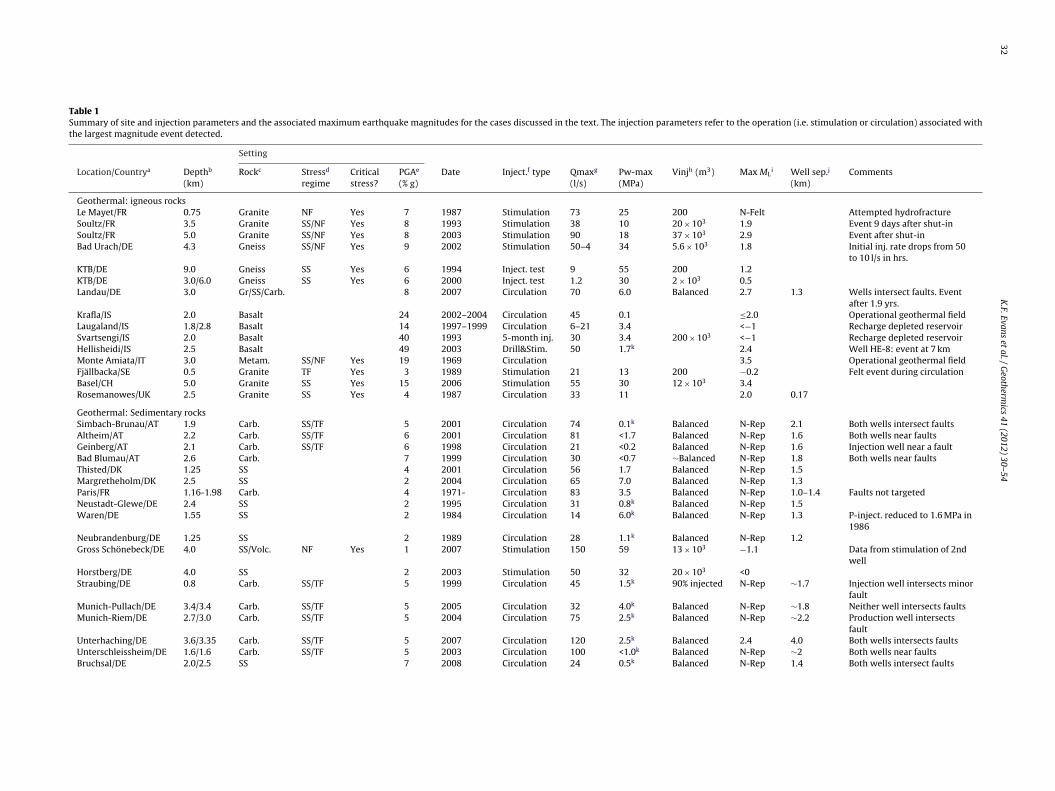
Fig. 1. Location of injection sites discussed in the paper shown on a Mercator projection. There are four sites in the Munich area that are considered: Riem, Pul-l obal sh of loa 50 ye
hdilonTWare
taabiarlfwia
sbsgtP
ach, Unterschleissheim and Unterhaching. The background is taken from the glttp://www.seismo.ethz.ch/static/GSHAP. The color scale denote the GSHAP indexcceleration (PGA) in %g on stiff soil that has a 10% probability of being exceeded in
The scope of this study is limited to reporting European caseistories of injection-related seismicity, including the project toevelop an EGS beneath the city of Basel in 2006. Most, if not all
ncidences of injection into crystalline rocks are included, regard-ess of whether events were felt. However, at this stage our coveragef injection into sedimentary rocks is not complete, especially foron-geothermal injections that did not produce felt earthquakes.wo sites where CO2 is injected into sedimentary rock are included.e exclude from consideration other types of induced seismicity
ssociated with such activities as fluid withdrawal, excavation oreservoir impoundment since these may involve somewhat differ-nt mechanisms.
The case histories of injections into igneous and sedimentaryarget rocks are presented in separate sections and are orderedlphabetically according to country. This structuring has the dis-dvantage that case histories from the same geological provinceut different countries are not reported contiguously, although the
ncidences are few. The locations of the sites are shown in Fig. 1, and summary listing of parameters for the sites is given in Table 1. Aock mass will be referred to as ‘critically stressed’ if the shear stressevel it supports would produce failure of an optimally orientedracture whose strength is described by Coulomb friction criterionith a coefficient 0.65. The maximum and minimum principal hor-
zontal stresses will be denoted by SHmax and Shmin, respectively,nd the vertical stress by SV.
For the purpose of comparing the natural seismic activity at aite, we used an index of estimated local seismic hazard which isased on an assessment for all of Europe that conforms to a single
tandard. This hazard is quantified in Table 1 and Fig. 1 by the peakround acceleration (PGA) in units of ‘g’, the acceleration of gravityaken from the compilation of Giardini et al. (1999). The value ofGA for a site denotes the acceleration level on stiff soil that haseismic hazard map of the Global Seismic Hazard Assessment Program (GSHAP)cal seismic hazard from natural earthquakes defined in terms of the peak groundars (equivalent to a recurrence period of 475 years).
a 10% probability of being exceeded in 50 years (equivalent to arecurrence period of 475 years). Regions of low hazard are charac-terised by values below 0.08 g, high hazard areas have PGAs above0.24 g, and moderate hazard regions present intermediate values.It should be emphasised that this value is not necessarily a measureof the seismogenic response of the ground to injection, but rather,is a conveniently available index of natural seismic hazard at a sitethat is based on the peak earthquake-induced shaking that is likelyto occur at the site. Consequently, PGA values will be high for locali-ties with no natural seismicity if it neighbours a region where largeevents occur. Such situations are noted in the text.
Throughout this report, seismic magnitudes are given aseither local magnitude, ML, duration magnitude, MD or moment-magnitude, MW. Whenever possible, macroseismic intensities aregiven in terms of the EMS-98 scale (Grüntal et al., 1998) anddenoted ‘Io(EMS)’. Most macroseismic intensities given in thispaper were derived before EMS-98 was defined. These values aredenoted as ‘Io’ and should be broadly consistent with the EMS-98classification. The most likely difference is that indistinct valuessuch as Io = IV–V or Io = VI–VII would most probably be assessed asIo(EMS) = IV and Io(EMS) = VI respectively in the EMS-98 classifica-tion.
2. Geothermal injection case histories: igneous rocks
2.1. France
2.1.1. Le Mayet de Montagne, France
The site is located 25 km south-east of Vichy, France, at thenorthern fringe of the Massif Central where the granite outcrops.It was established in 1985 as an EGS test site with two boreholesdrilled to 800 m depth. The local stress state is characterised as
32K
.F. Evans
et al.
/ G
eothermics
41 (2012) 30– 54
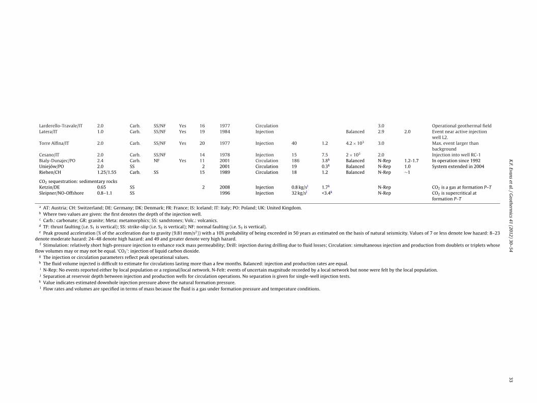
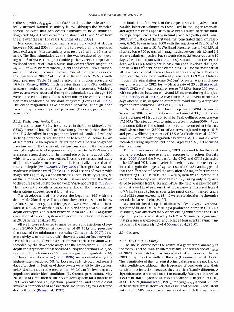
Table 1Summary of site and injection parameters and the associated maximum earthquake magnitudes for the cases discussed in the text. The injection parameters refer to the operation (i.e. stimulation or circulation) associated withthe largest magnitude event detected.
Setting
Location/Countrya Depthb
(km)Rockc Stressd
regimeCriticalstress?
PGAe
(% g)Date Inject.f type Qmaxg
(l/s)Pw-max(MPa)
Vinjh (m3) Max MLi Well sep.j
(km)Comments
Geothermal: igneous rocksLe Mayet/FR 0.75 Granite NF Yes 7 1987 Stimulation 73 25 200 N-Felt Attempted hydrofractureSoultz/FR 3.5 Granite SS/NF Yes 8 1993 Stimulation 38 10 20 × 103 1.9 Event 9 days after shut-inSoultz/FR 5.0 Granite SS/NF Yes 8 2003 Stimulation 90 18 37 × 103 2.9 Event after shut-inBad Urach/DE 4.3 Gneiss SS/NF Yes 9 2002 Stimulation 50–4 34 5.6 × 10³ 1.8 Initial inj. rate drops from 50
to 10 l/s in hrs.KTB/DE 9.0 Gneiss SS Yes 6 1994 Inject. test 9 55 200 1.2KTB/DE 3.0/6.0 Gneiss SS Yes 6 2000 Inject. test 1.2 30 2 × 10³ 0.5Landau/DE 3.0 Gr/SS/Carb. 8 2007 Circulation 70 6.0 Balanced 2.7 1.3 Wells intersect faults. Event
after 1.9 yrs.Krafla/IS 2.0 Basalt 24 2002–2004 Circulation 45 0.1 ≤2.0 Operational geothermal fieldLaugaland/IS 1.8/2.8 Basalt 14 1997–1999 Circulation 6–21 3.4 <−1 Recharge depleted reservoirSvartsengi/IS 2.0 Basalt 40 1993 5-month inj. 30 3.4 200 × 103 <−1 Recharge depleted reservoirHellisheidi/IS 2.5 Basalt 49 2003 Drill&Stim. 50 1.7k 2.4 Well HE-8: event at 7 kmMonte Amiata/IT 3.0 Metam. SS/NF Yes 19 1969 Circulation 3.5 Operational geothermal fieldFjällbacka/SE 0.5 Granite TF Yes 3 1989 Stimulation 21 13 200 −0.2 Felt event during circulationBasel/CH 5.0 Granite SS Yes 15 2006 Stimulation 55 30 12 × 103 3.4Rosemanowes/UK 2.5 Granite SS Yes 4 1987 Circulation 33 11 2.0 0.17
Geothermal: Sedimentary rocksSimbach-Brunau/AT 1.9 Carb. SS/TF 5 2001 Circulation 74 0.1k Balanced N-Rep 2.1 Both wells intersect faultsAltheim/AT 2.2 Carb. SS/TF 6 2001 Circulation 81 <1.7 Balanced N-Rep 1.6 Both wells near faultsGeinberg/AT 2.1 Carb. SS/TF 6 1998 Circulation 21 <0.2 Balanced N-Rep 1.6 Injection well near a faultBad Blumau/AT 2.6 Carb. 7 1999 Circulation 30 <0.7 ∼Balanced N-Rep 1.8 Both wells near faultsThisted/DK 1.25 SS 4 2001 Circulation 56 1.7 Balanced N-Rep 1.5Margretheholm/DK 2.5 SS 2 2004 Circulation 65 7.0 Balanced N-Rep 1.3Paris/FR 1.16-1.98 Carb. 4 1971- Circulation 83 3.5 Balanced N-Rep 1.0–1.4 Faults not targetedNeustadt-Glewe/DE 2.4 SS 2 1995 Circulation 31 0.8k Balanced N-Rep 1.5Waren/DE 1.55 SS 2 1984 Circulation 14 6.0k Balanced N-Rep 1.3 P-inject. reduced to 1.6 MPa in
1986Neubrandenburg/DE 1.25 SS 2 1989 Circulation 28 1.1k Balanced N-Rep 1.2Gross Schönebeck/DE 4.0 SS/Volc. NF Yes 1 2007 Stimulation 150 59 13 × 103 −1.1 Data from stimulation of 2nd
wellHorstberg/DE 4.0 SS 2 2003 Stimulation 50 32 20 × 103 <0Straubing/DE 0.8 Carb. SS/TF 5 1999 Circulation 45 1.5k 90% injected N-Rep ∼1.7 Injection well intersects minor
faultMunich-Pullach/DE 3.4/3.4 Carb. SS/TF 5 2005 Circulation 32 4.0k Balanced N-Rep ∼1.8 Neither well intersects faultsMunich-Riem/DE 2.7/3.0 Carb. SS/TF 5 2004 Circulation 75 2.5k Balanced N-Rep ∼2.2 Production well intersects
faultUnterhaching/DE 3.6/3.35 Carb. SS/TF 5 2007 Circulation 120 2.5k Balanced 2.4 4.0 Both wells intersects faultsUnterschleissheim/DE 1.6/1.6 Carb. SS/TF 5 2003 Circulation 100 <1.0k Balanced N-Rep ∼2 Both wells near faultsBruchsal/DE 2.0/2.5 SS 7 2008 Circulation 24 0.5k Balanced N-Rep 1.4 Both wells intersect faults
K.F.
Evans et
al. /
Geotherm
ics 41 (2012) 30– 54
33
Larderello-Travale/IT 2.0 Carb. SS/NF Yes 16 1977 Circulation 3.0 Operational geothermal fieldLatera/IT 1.0 Carb. SS/NF Yes 19 1984 Injection Balanced 2.9 2.0 Event near active injection
well L2.Torre Alfina/IT 2.0 Carb. SS/NF Yes 20 1977 Injection 40 1.2 4.2 × 10³ 3.0 Max. event larger than
backgroundCesano/IT 2.0 Carb. SS/NF 14 1978 Injection 15 7.5 2 × 10³ 2.0 Injection into well RC-1Bialy-Dunajec/PO 2.4 Carb. NF Yes 11 2001 Circulation 186 3.8k Balanced N-Rep 1.2-1.7 In operation since 1992Uniejów/PO 2.0 SS 2 2001 Circulation 19 0.3k Balanced N-Rep 1.0 System extended in 2004Riehen/CH 1.25/1.55 Carb. SS 15 1989 Circulation 18 1.2 Balanced N-Rep ∼1
CO2 sequestration: sedimentary rocksKetzin/DE 0.65 SS 2 2008 Injection 0.8 kg/sl 1.7k N-Rep CO2 is a gas at formation P–TSleipner/NO-Offshore 0.8–1.1 SS 1996 Injection 32 kg/sl <3.4k N-Rep CO2 is supercritical at
formation P–T
a AT: Austria; CH: Switzerland; DE: Germany; DK: Denmark; FR: France; IS: Iceland; IT: Italy; PO: Poland; UK: United Kingdom.b Where two values are given: the first denotes the depth of the injection well.c Carb.: carbonate; GR: granite; Meta: metamorphics; SS: sandstones; Volc.: volcanics.d TF: thrust faulting (i.e. S1 is vertical); SS: strike-slip (i.e. S2 is vertical); NF: normal faulting (i.e. S3 is vertical).e Peak ground acceleration (% of the acceleration due to gravity (9.81 mm/s2)) with a 10% probability of being exceeded in 50 years as estimated on the basis of natural seismicity. Values of 7 or less denote low hazard: 8–23
denote moderate hazard: 24–48 denote high hazard: and 49 and greater denote very high hazard.f Stimulation: relatively short high-pressure injection to enhance rock mass permeability; Drill: injection during drilling due to fluid losses; Circulation: simultaneous injection and production from doublets or triplets whose
flow volumes may or may not be equal. ‘CO2’: injection of liquid carbon dioxide.g The injection or circulation parameters reflect peak operational values.h The fluid volume injected is difficult to estimate for circulations lasting more than a few months. Balanced: injection and production rates are equal.i N-Rep: No events reported either by local population or a regional/local network. N-Felt: events of uncertain magnitude recorded by a local network but none were felt by the local population.j Separation at reservoir depth between injection and production wells for circulation operations. No separation is given for single-well injection tests.k Value indicates estimated downhole injection pressure above the natural formation pressure.l Flow rates and volumes are specified in terms of mass because the fluid is a gas under formation pressure and temperature conditions.
3 therm
sirmt
bhaiwMoth1pfwtTwJ
2
(tRosamwormmotTo
d1ldci
itmTrdt1hdnp21id
4 K.F. Evans et al. / Geo
trike-slip with a Shmin/SV ratio of 0.55, and thus the rocks are crit-cally stressed. Natural seismicity is low, although the historicalecord indicates that two events estimated to be of moment-agnitude MW 4.3 have occurred at distances of 16 and 27 km from
he site over the last 130 years (Grünthal et al., 2009).Numerous injection experiments were conducted at depths
etween 400 and 800 m in attempts to develop an undergroundeat exchanger. Microseismicity was recorded with a 15-stationrray. The first stimulation at the site was conducted by inject-ng 61 m3 of water through a double packer at 443 m depth at a
ellhead pressure of 19 MPa. Six seismic events of local magnitudeL −1.3 to −0.9 were recorded (Talebi and Cornet, 1987). Numer-
us stimulation injections followed. One of the largest involvedhe injection of 200 m3 of fluid at 73 l/s and up to 25 MPa well-ead pressure (Table 1), and resulted in a shut-in pressure of6 MPa (Cornet, 1989), much greater than the 4 MPa wellheadressure needed to attain Shmin within the reservoir. Relativelyew events were recorded during the stimulations, although 140ere detected at depths of 400–800 m during the various circula-
ion tests conducted on the doublet system (Evans et al., 1992).he event magnitudes have not been reported, although noneere felt by the on site project personnel (F. Cornet, pers. comm.,
une 2009).
.1.2. Soultz-sous-Forêts, FranceThe Soultz-sous-Forêts site is located in the Upper Rhine Graben
URG), some 40 km NNE of Strasbourg, France (other sites inhe URG described in this paper are Bruchsal, Landau, Basel andiehen). At the Soultz site, the granitic basement lies below 1.4 kmf sediments. Graben-parallel faults produce a horst-and-grabentructure within the basement. Fracture zones within the basementre high-angle and strike approximately normal to the E–W averageinimum stress direction. The magnitude of Shmin is about 0.5SV,hich is typical of a graben setting. Thus, the rock mass, and many
f the large-scale structures within it, is critically stressed at alleservoir depths (Evans, 2005; Valley, 2007). The region has low-to-oderate seismic hazard (Table 1). In 1954 a series of events withagnitudes up to ML 4.8 and intensities up to Intensity Io(EMS) VI
n the European Macroseismic Scale (EMS-98) occurred 10–20 kmo the southeast of Soultz towards Seltz/Wissenbourg (Helm, 1996).he hypocentre depth is uncertain although the macroseismicbservations suggest several kilometres.
The development of the project site began in 1987 with therilling of a 2 km deep well to explore the granitic basement below.4 km. Subsequently, a doublet system was developed and circu-
ated at 3.0–3.5 km depth in 1992–1997, and a triplet at 4.5–5.0 kmepth developed and tested between 1998 and 2009. Long-termirculation of the deep system with power production commencedn 2010 (Genter et al., 2010).
All wells were subjected to massive hydraulic injections of typ-cally 20,000–40,000 m3 at flow rates of 40–80 l/s and pressureshat reached the minimum stress value (Cornet et al., 2007). Seis-
ic activity was monitored with downhole and surface networks.ens of thousands of events associated with each stimulation wereecorded by the downhole array. For the reservoir at 3.0–3.5 kmepth, the largest event that occurred during the first massive injec-ion into the rock mass in 1993 was assigned a magnitude of ML.7 from the surface array (Helm, 1996) and occurred during theighest-rate injection of 36 l/s. However, a ML 1.9 occurred some 9ays after shut-in. Neither of these events were felt by site person-el. At Soultz, magnitudes greater than ML 2.0 can felt by the nearbyopulation under ideal conditions (N. Cuenot, pers. comm., May
010). Fluid circulation of the 3.5 km deep system for 4 months in997 was balanced (i.e., injection = production), and hence did notnvolve a component of net injection. No seismicity was detecteduring this test (Baria et al., 1997).
ics 41 (2012) 30– 54
Stimulation of the wells of the deeper reservoir involved com-parable injection volumes to those used in the upper reservoir,and again pressures appear to have been limited near the mini-mum principal stress level by natural processes (Valley and Evans,2007). Stimulation of the first well that penetrated the 5 km reser-voir, GPK2, began in June 2000 with the injection of 22,000 m3 ofwater at rates of up to 50 l/s. Wellhead pressure rose to 14.5 MPa atshut-in. Some 700 events with magnitudes between ML 1.0 and 2.5occurred during injection, but a magnitude ML 2.6 occurred some 10days after shut-in (Dorbath et al., 2009). Stimulation of the seconddeep well, GPK3, took place in May 2003 and involved the injec-tion of 34,000 m3 of brine and water into GPK3, for the most part at50 l/s with occasional increases for a few hours of up to 90 l/s whichproduced the maximum wellhead pressure of 17.9 MPa. Midwaythrough the stimulation, some 3400 m3 of water was simultane-ously injected into GPK2 for ∼40 h at a rate of 20 l/s (Baria et al.,2004). GPK2 wellhead pressure rose to 7.9 MPa. Some 200 eventswith magnitudes between ML 1.0 and 2.5 occurred during this injec-tion (Charléty et al., 2007). A magnitude ML 2.9 event occurred 2days after shut-in, despite an attempt to avoid this by a stepwiseinjection rate reduction (Baria et al., 2004).
The stimulation of the third deep well, GPK4, began inSeptember 2004. Injection rate was maintained at 30 l/s with a fewshort increases of 2 h duration to 44 l/s. Peak wellhead pressure was17.5 MPa. The injection was terminated after injecting 9000 m3 dueto a pump failure. The stimulation program resumed in February2005 when a further 12,500 m3 of water was injected at up to 45 l/sand peak wellhead pressures of 18.5 MPa (Dorbath et al., 2009).Some 128 events with magnitudes between ML 1.0 and 2.7 wererecorded during injection, but none larger than ML 2.0 occurredduring shut-in.
Of the three deep Soultz wells, GPK3 appeared to be the mostprone to produce large events in response to injection. Dorbathet al. (2009) found the b-values for the GPK2 and GPK3 seismicityto be 1.23 and 0.94, respectively (although only over the respectivelimited magnitude ranges of ML 1.0–1.9 and 1.0–2.3), and suggestedthat the difference reflected the activation of a major fracture zoneintersecting GPK3. In 2005, the 3-well system was subjected to a6-month close-loop circulation test at 15 l/s using only buoyancydrive to produce from GPK2 and GPK4. The fluid was injected intoGPK3 at a wellhead pressure that progressively increased from 4to 7 MPa. Seismicity began soon after injection commenced, and atotal of 32 events exceeding ML 1.2 were recorded during the entireperiod, the largest being ML 2.3.
A 2-month closed-loop circulation test of wells GPK2–GPK3 wasperformed in 2008 at 25 l/s using a production pump in GPK2. Noseismicity was observed for 5 weeks during which time the GPK3injection pressure rose steadily to 6 MPa. Seismicity began oncethat pressure was exceeded, and included four events having mag-nitudes in the range ML 1.3–1.4 (Cuenot et al., 2010).
2.2. Germany
2.2.1. Bad Urach, GermanyThe site is located near the centre of a geothermal anomaly in
the foothills of the Swabian Alb mountains. The orientation of SHmaxof N82◦E is well defined by breakouts that are observed below1900 m depth in the wells at the site (Heinemann et al., 1992).The magnitudes of the horizontal principal stresses are not knownwith confidence, although the frequency of breakouts and theirconsistent orientation suggests they are significantly different. A‘hydrofracture’ stress test on a 1 m naturally fractured interval at
3350 m in Urach-3 yielded an instantaneous shut-in pressure (ISIP)of 41–50 MPa (Rummel et al., 1991), implying Shmin is about 50–55%of the vertical stress. However, this value is not obviously consistentwith the 33 MPa overpressure sustained in the 168 m open-hole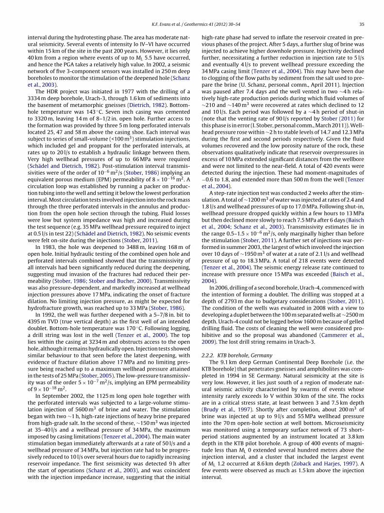
therm
iuw4anbe
3thttlswrV(sectittwtaw
opasmwidh
4dalhsesiio
tlbfaiswsrtw
K.F. Evans et al. / Geo
nterval during the hydrotesting phase. The area has moderate nat-ral seismicity. Several events of intensity Io IV–VI have occurredithin 15 km of the site in the past 200 years. However, it lies only
0 km from a region where events of up to ML 5.5 have occurred,nd hence the PGA takes a relatively high value. In 2002, a seismicetwork of five 3-component sensors was installed in 250 m deeporeholes to monitor the stimulation of the deepened hole (Schanzt al., 2003).
The HDR project was initiated in 1977 with the drilling of a334 m deep borehole, Urach-3, through 1.6 km of sediments intohe basement of metamorphic gneisses (Dietrich, 1982). Bottom-ole temperature was 143 ◦C. Seven inch casing was cementedo 3320 m, leaving 14 m of 8–1/2 in. open hole. Further access tohe formation was provided by three 5 m long perforated intervalsocated 25, 47 and 58 m above the casing shoe. Each interval wasubject to series of small-volume (<100 m3) stimulation injections,hich included gel and proppant for the perforated intervals, at
ates up to 20 l/s to establish a hydraulic linkage between them.ery high wellhead pressures of up to 66 MPa were required
Schädel and Dietrich, 1982). Post-stimulation interval transmis-ivities were of the order of 10−6 m2/s (Stober, 1986) implying anquivalent porous medium (EPM) permeability of 8 × 10⁻¹⁶ m2. Airculation loop was established by running a packer on produc-ion tubing into the well and setting it below the lowest perforationnterval. Most circulation tests involved injection into the rock masshrough the three perforated intervals in the annulus and produc-ion from the open hole section through the tubing. Fluid lossesere low but system impedance was high and increased during
he test sequence (e.g. 35 MPa wellhead pressure required to injectt 0.5 l/s in test 22) (Schädel and Dietrich, 1982). No seismic eventsere felt on-site during the injections (Stober, 2011).
In 1983, the hole was deepened to 3488 m, leaving 168 m ofpen hole. Initial hydraulic testing of the combined open hole anderforated intervals combined showed that the transmissivity ofll intervals had been significantly reduced during the deepening,uggesting mud invasion of the fractures had reduced their per-eability (Stober, 1986; Stober and Bucher, 2000). Transmissivityas also pressure-dependent, and markedly increased at wellhead
njection pressures above 17 MPa, indicating the onset of fractureilation. No limiting injection pressure, as might be expected forydrofracture growth, was reached up to 33 MPa (Stober, 1986).
In 1992, the well was further deepened with a 5–7/8 in. bit to395 m TVD (true vertical depth) as the first well of an intendedoublet. Bottom-hole temperature was 170 ◦C. Following logging,
drill string was lost in the well (Tenzer et al., 2000). The topies within the casing at 3234 m and obstructs access to the openole, although it remains hydraulically open. Injection tests showedimilar behaviour to that seen before the latest deepening, withvidence of fracture dilation above 17 MPa and no limiting pres-ure being reached up to a maximum wellhead pressure attainedn the tests of 25 MPa (Stober, 2005). The low-pressure transmissiv-ty was of the order 5 × 10⁻⁷ m2/s, implying an EPM permeabilityf 9 × 10⁻¹⁸ m2.
In September 2002, the 1125 m long open hole together withhe perforated intervals was subjected to a large-volume stimu-ation injection of 5600 m3 of brine and water. The stimulationegan with two ∼1 h, high-rate injections of heavy brine preparedrom high-grade salt. In the second of these, ∼150 m3 was injectedt 35–40 l/s and a wellhead pressure of 34 MPa, the maximummposed by casing limitations (Tenzer et al., 2004). The main watertimulation began immediately afterwards at a rate of 50 l/s and aellhead pressure of 34 MPa, but injection rate had to be progres-
ively reduced to 10 l/s over several hours due to rapidly increasingeservoir impedance. The first seismicity was detected 9 h afterhe start of operations (Schanz et al., 2003), and was coincidentith the injection impedance increase, suggesting that the initial
ics 41 (2012) 30– 54 35
high-rate phase had served to inflate the reservoir created in pre-vious phases of the project. After 5 days, a further slug of brine wasinjected to achieve higher downhole pressure. Injectivity declinedfurther, necessitating a further reduction in injection rate to 5 l/sand eventually 4 l/s to prevent wellhead pressure exceeding the34 MPa casing limit (Tenzer et al., 2004). This may have been dueto clogging of the flow paths by sediment from the salt used to pre-pare the brine (U. Schanz, personal comm., April 2011). Injectionwas paused after 7.4 days and the well vented in two ∼4 h rela-tively high-rate production periods during which fluid volumes of∼210 and ∼140 m3 were recovered at rates which declined to 12and 10 l/s. Each period was followed by a ∼4 h period of shut-in(note that the venting rate of 90 l/s reported by Stober (2011) forthis phase is in error (I. Stober, personal comm., March 2011)). Well-head pressure rose within ∼2 h to stable levels of 14.7 and 12.3 MPaduring the first and second periods respectively. Given the fluidvolumes recovered and the low porosity nature of the rock, theseobservations qualitatively indicate that reservoir overpressures inexcess of 10 MPa extended significant distances from the wellboreand were not limited to the near-field. A total of 420 events weredetected during the injection. These had moment-magnitudes of−0.6 to 1.8, and extended more than 500 m from the well (Tenzeret al., 2004).
A step-rate injection test was conducted 2 weeks after the stim-ulation. A total of ∼1200 m3 of water was injected at rates of 2.4 and1.8 l/s and wellhead pressures of up to 17.0 MPa. Following shut-in,wellhead pressure dropped quickly within a few hours to 13 MPabut then declined more slowly to reach 7.5 MPa after 6 days (Baischet al., 2004; Schanz et al., 2003). Transmissivity estimates lie inthe range 0.5–1.5 × 10⁻⁶ m2/s, only marginally higher than beforethe stimulation (Stober, 2011). A further set of injections was per-formed in summer 2003, the largest of which involved the injectionover 10 days of ∼1950 m3 of water at a rate of 2.1 l/s and wellheadpressure of up to 18.3 MPa. A total of 218 events were detected(Tenzer et al., 2004). The seismic energy release rate continued toincrease with pressure once 15 MPa was exceeded (Baisch et al.,2004).
In 2006, drilling of a second borehole, Urach-4, commenced withthe intention of forming a doublet. The drilling was stopped at adepth of 2793 m due to budgetary considerations (Stober, 2011).The condition of the wells was evaluated in 2008 with a view todeveloping a duplet between the 100 m separated wells at ∼2500 mdepth. Urach-4 could not be logged below 1600 m because of gelleddrilling fluid. The costs of cleaning the well were considered pro-hibitive and so the proposal was abandoned (Cammerer et al.,2009). The lost drill string remains in Urach-3.
2.2.2. KTB borehole, GermanyThe 9.1 km deep German Continental Deep Borehole (i.e. the
KTB borehole) that penetrates gneisses and amphibolites was com-pleted in 1994 in SE Germany. Natural seismicity at the site isvery low. However, it lies just south of a region of moderate nat-ural seismic activity characterised by swarms of events whoseintensity rarely exceeds Io V within 30 km of the site. The rocksare in a critical stress state, at least between 3 and 7.5 km depth(Brudy et al., 1997). Shortly after completion, about 200 m3 ofbrine was injected at up to 9 l/s and 55 MPa wellhead pressureinto the 70 m open-hole section at well bottom. Microseismicitywas monitored using a temporary surface network of 73 short-period stations augmented by an instrument located at 3.8 kmdepth in the KTB pilot borehole. A group of 400 events of magni-tude less than ML 0 extended several hundred metres above the
injection interval, and a cluster that included the largest eventof ML 1.2 occurred at 8.6 km depth (Zoback and Harjes, 1997). Afew events were observed as much as 1.5 km above the injectioninterval.
3 therm
a633l6aomap9bi
2
ttsiislsmircoesUsseaus
optd1tfLawes
ftft2Lmi2oce
6 K.F. Evans et al. / Geo
In 2000, a larger injection of 4000 m3 of water was performedt flow rates of up to 1.2 l/s and wellhead pressures of 30 MPa over0 days. The injection was monitored by a surface network of 40-component stations augmented with a downhole instrument at.8 km in the pilot borehole. A total of ∼2800 seismic events were
ocated. The vast majority were found to be clustered at 3.3, 5.4,.6 km, as well as near the hole bottom at 9.0 km. These depthsre believed to reflect points where fluid flow into the rock massccurred, through casing leaks or open hole. The maximum eventagnitude was ML 0.5 (Baisch and Harjes, 2003). More recently,
10-month injection test was conducted into the 4.0 km deepilot hole at a constant rate of ∼3 l/s and a wellhead pressure of–12 MPa. Some 3000 events were recorded (Shapiro et al., 2006),ut they were of lower magnitude than those in the earlier exper-
ments (Kümpel et al., 2006).
.2.3. Landau, GermanyThis dual use (electricity/district heating) project is located in
he Upper Rhine Graben some 35 km NE of Soultz (Fig. 1). The injec-ion occurs into both basement and the lowermost units of theedimentary section, and so this site could equally well be includedn Section 3 on sedimentary rock (Schindler et al., 2010). The localitys cut by high-angle faults that strike N–S (Illies and Greiner, 1978),ub-parallel to the NNE–SSW strike of the graben. There is no pub-ished stress information for the site. However, given the grabenetting, the focal mechanism solutions of local earthquakes and theeasured stress state at the Soultz EGS site, it is likely that Shmin
s oriented E–W to SW–NE, and is substantially less than SV. Theegion has low-to-moderate natural seismic activity with histori-al events that produced maximum intensities of up to Io VII–VIIIn the European Macroseismic Scale (EMS-98). An event with anstimated maximum intensity of Io VII occurred some 10 km to theouth of Landau, near Kandel in 1903 (Ahorner et al., 1970b). For thepper Rhine Graben region, a maximum intensity Io(EMS) VII for
hallow events corresponds to a magnitude ML of 4.0–4.5. Macro-eismic observations suggest a depth of a few kilometres (Ahornert al., 1970b). The site borders an oilfield that has produced oil from
formation at 1.1 km depth since 1955 (Doebl, 1968) and contin-es to do so today. Long-term fluid extraction can be a source ofeismicity (Van Eck et al., 2006).
During 2005 and 2006, two boreholes were drilled deviated inpposite E–W directions so as to penetrate faults that cut relativelyermeable carbonates and sandstones at the base of the sedimen-ary section and the uppermost level of the basement at ∼3 kmepth (Schindler et al., 2010). Well separation at reservoir depth is.3 km. The faults are believed to intersect some distance north ofhe site, and so flow within the reservoir is complex and probablyault-controlled (Baumgärtner et al., 2010b). The injection well, Gt-a2, was subjected to a hydraulic stimulation at rates of up to 190 l/snd wellhead pressures of 13.5 MPa (Hettkamp et al., 2007). Thereas no felt seismicity associated with this operation (Baumgärtner
t al., 2010a). The production well, Gt-La1, did not require hydraulictimulation because it intersected a highly transmissive fault.
The doublet was tested during 2007, and power productionrom a 3.8 MWe ORC plant was demonstrated in November ofhat year. A balanced circulation rate of ∼65 l/s was maintainedrom February to November 2008, during which time the injec-ion pressure declined from 6.0 to 3.0 MPa (Baumgärtner et al.,010a). Following the installation of a downhole pump in Gt-a1, circulation at 70 l/s resumed in February and continued untilid-September 2009. Injection pressure during this time steadily
ncreased from 4.0 MPa to almost 5.5 MPa (Baumgärtner et al.,
010a). In February 2008, two small earthquakes with magnitudesf ML 1.7 and 1.8 were recorded in the area by the Seismologi-al Services of Baden-Württemberg and Rheinland-Pfalz. Anothervent of ML 1.7 occurred in the area in October 2008, and threeics 41 (2012) 30– 54
further events of magnitudes ML 1.6–1.9 were detected in the areaon 9 May 2009. Although these events occurred in the area of Lan-dau, their depths were not well constrained. On 15 August 2009,an ML 2.7 event that was felt by the population of Landau occurredshortly after operation of the system had been halted for mainte-nance operations. The event hypocentre was located by an expertgroup as lying 1.5–2.0 km north of the plant at a depth of 2.3–3.3 km(Bönnemann et al., 2010). Thus the failure area could lie either inthe sediments or the basement or both. A further seven eventswere recorded on the same day. The plant resumed operation inNovember 2009 with the maximum injection pressure lowered to4.5 MPa.
A similar dual use project is being developed about 5 km southof Landau near Insheim. Drilling and initial testing of the sec-ond well of the doublet was completed in 2009 (Baumgärtneret al., 2010a). In September 2009 the Seismological Services ofBaden-Württemberg and Rheinland-Pfalz recorded five events ofmagnitude approximately ML 2.0 within a few kilometres of the site(LED-LGRB, 2010). The relationship of these events to operations atthe site is unclear.
2.3. Iceland
Geothermal well injection in Iceland is used both for reser-voir stimulation and pressure maintenance or recharge. In mostcases, injection takes place at pressures less than several MPa oris gravity-driven since the basalt reservoirs tend to have relativelyhigh natural transmissibility. The reservoirs and hence the injec-tion horizons also tend to be comparatively shallow, the deepestinjection well being 2.8 km. Many geothermal areas experienceintermittent phases of natural seismic activity that are clearly unre-lated to fluid injection or other human activities. Here we describefour sites where the seismic response to injection has been docu-mented.
2.3.1. KraflaGeothermal power has been generated at Krafla since 1977.
A 60 MWe power station is located in the Krafla caldera, whichwas the source of a series of eruptions and intrusions associatedwith crustal accretion that took place between 1975 and 1984(Gudmundsson, 2001). The magmatic events were accompaniedby considerable seismicity which subsequently declined to lowlevels. Analysis of focal mechanisms of earthquakes up to magni-tude ML 2.1 occurring 1 year after the termination of the eruptionsindicated that a heterogeneous stress field prevailed at that time(Foulger et al., 1989). Some of the events were believed to resultfrom heat-mining operations. In 2004 a passive seismic experimentwas performed around the main injection well KG-26 of the high-temperature Krafla-Leirhnúkur field, which is located within thecaldera, 1 km north of the power station. This well supplies fluidto the lower reservoir at a depth of 2.0–2.1 km (Tang et al., 2005a),and had been used as an injector more-or-less continuously since2002 at rates of up to 70 l/s and wellhead pressures of 0.3 MPa.In 2004, the rate and wellhead pressure were 45 l/s and 0.1 MPa(Á. Gudmundsson, pers. comm., July 2010). The seismic activityand velocity structure (including anisotropy) near the well weremonitored for 2 months with two 20-station 3-component arrays(Onacha et al., 2005). During this period, injection into K-26 washalted for 11 days to study the effect on seismicity and velocitystructure. An average of four locatable seismic events per day ofmagnitudes less than ML 2.0 were detected (Tang et al., 2008). Thehypocentres lay between 1 and 3 km depth, and defined a predom-
inantly E–W trend near the well (Kahn, 2008; Tang et al., 2008).Consequently, it is likely the majority of events were associatedwith injection, although no obvious change in event frequencyaccompanied the halt in injection (Tang et al., 2005b). However,
therm
siot
2
d2hpatb(
2
r2a5awiue
2
aneonsmTpbte
oHwaidepiwecsamdaa
2iow
K.F. Evans et al. / Geo
hear velocities along local raypaths around the well increased dur-ng the halt in injection, implying the closure of fractures that werepen during injection (Tang et al., 2005a). This is consistent withhe observation of shear-wave velocity anisotropy.
.3.2. LaugalandThis is a low-temperature field in central N-Iceland where pro-
uction had resulted in a pressure drop of 3.5 MPa (Axelsson et al.,000). To recharge the reservoir, 15–20 ◦C water from the districteating system was injected at rates of 6–21 kg/s and wellheadressures of up to 2.8 MPa into two deep wells (1.6 and 2.8 km) over
2-year period. Microseismic activity was monitored throughouthe operations by a network with a detection threshold of ML −1,ut no events that could be ascribed to the injection were recordedAxelsson et al., 2000).
.3.3. SvartsengiExploitation of this high-temperature field since 1976 had
esulted in a 2 MPa drop in reservoir pressure (Brandsdóttir et al.,002). In 1984, intermittent injection of 70–80 ◦C waste water into
2.0 km deep well commenced with year-averaged rates as high as5 l/s. A single seismometer installed on site in 1984 failed to detectny events within the field through 2001. The single instrumentas supplemented by a 16-instrument array for a 5-month period
n 1993 when 217,000 m3 of water was injected at rates up to 30 l/snder gravity, but again no events were recorded (Brandsdóttirt al., 2002).
.3.4. HengillThis extensive geothermal area is located at a triple-junction in
volcanically active region. Two geothermal fields lie immediatelyorth and south of the Hengill volcano. The area is characterised bypisodes of natural seismic swarm activity, and two ML 5.0 eventsccurred in 1998 (Agustsson and Halldorsson, 2005). Consequently,umerous studies have been conducted in the area to assess theeismic hazard (Agustsson and Halldorsson, 2005) and for geother-al exploration purposes (Arnason et al., 2010; Tang et al., 2006).
he field to the north, called Nesjavellir, is one of the highest tem-erature geothermal systems under exploitation in Iceland and haseen producing power since 1987 (Arnason et al., 2010). The fieldo the south, called Hellisheidi, is also high-temperature and wasxplored somewhat later. It began producing power in 2006.
Significant injection-induced microseismicity appears to haveccurred during the drilling and stimulation of a 2.8 km deep wellE-8 in the Hellisheidi field in 2003 (Bjornsson, 2004). The areaithin a few kilometres of the well had been microseismically
ctive between 1995 and 1999, possibly associated with activ-ty at Mt. Hengill, but had been largely quiet since then. Duringrilling, water was lost into the formation at rates of 20–50 l/s,ssentially constituting injection (Bjornsson, 2004). Drilling wasaused at 2500 m and the hot well stimulated by intermittently
njecting cold water at up to 60 l/s for several days. This coincidedith the detection by the national seismic network of a series of
arthquakes below the well at depths provisionally given in theatalogue as 4–6 km. Shortly after drilling recommenced, anothereries of events occurred near the well, the largest of which had
magnitude ML 2.4 and a provisional depth of 7 km. After severalonths of shut-in, cold water was injected for 15 days at 50 l/s with
ownhole pressures of 1.7 MPa (Fig. 4 of Bjornsson (2004)). This wasccompanied by events with magnitudes in the ML −0.2–1.2 ranget depths between 4 and 6 km.
Similar behaviour was observed during injections into the
.0 km deep well HE-21 in the same field in February 2006. Follow-ng completion, the well had a low injectivity, and was stimulatedver a 3 days period by first circulating and then injecting coldater at progressively higher rates and downhole pressures up to
ics 41 (2012) 30– 54 37
1.8 MPa above the formation pressure (Axelsson et al., 2006). By theend of the operation, some 31 l/s of the fluid entered the formationat a downhole pressure of 1.4 MPa above the formation pressure(Mortensen et al., 2006). During this time, several small events ofmagnitude up to ML 2.0 were detected close to the well by thenational network of the Icelandic Meteorological Office (Axelssonet al., 2006; Vogfjörd and Hjaltadóttir, 2007). Consequently, two 3-component seismic stations were temporarily installed to improveevent detectability and location accuracy (K. Vogfjörd, pers. comm.,July 2010). Thermal stimulation operations resumed after 1 weekof shut-in with injection for 2 days at 65 l/s and a downhole over-pressure of 3.4 MPa (Mortensen et al., 2006). Most fluid enteredthe formation through a fracture zone at 1850 m. No events weredetected during injection although a few that were too small tolocate occurred 1–2 days later (Vogfjörd and Hjaltadóttir, 2007). Afew days later, a 2.5 day injection was conducted. The details of thisinjection are not currently available, although it appears that flowrates were not significantly higher than the earlier injection due tolimitation of the water source, which was two nearby groundwaterwells. Seismicity began after 24 h of injection and included a ML 2.7event. A total of 50 events could be located, the vast majority ofwhich lay between 1.0 and 2.5 km depth and defined a structurethat extended from the well towards the northeast (Vogfjörd andHjaltadóttir, 2007).
The four Icelandic examples above emphasise the importance ofstress criticality in injection-induced microseismicity. The Lauge-land and Svartsengi reservoirs had suffered pressure depletion,and thus injection would serve to restore the stress-state topre-exploitation conditions, whereas the Hellisheidi and Kraflareservoirs are located in zones which are undergoing, or haverecently undergone, tectonic activity, and hence the stress stateis more likely to be critical.
2.4. Italy
2.4.1. Monte Amiata areaThis area is located at the southern boundary of Tus-
cany, and contains the Piancastagnaio and Bagnore fields (Billiet al., 1986). Both fields have two reservoirs: a shallow one inevaporites/carbonates at 0.6–1.0 km depth, and a deeper, water-dominated reservoir in the metamorphic basement at 2.5–3.5 kmwith temperatures of 300–350 ◦C (Barelli et al., 2010; Bertiniet al., 2005). The level of background seismicity at the site is sub-stantial (Batini et al., 1980b, 1990), and tends to mask potentialinduced events. Studies of historical seismicity since year 1000AD indicate that a relatively large event occurred in the areathat produced intensity IX MCS shaking (Batini et al., 1990). An8 MWe power plant supplied with fluid from the deeper reser-voir was installed at Piancastagnaio in 1969 and was expanded to88 MWe in the middle-to-late 1990s through the addition of 20 MWplants.
A seismic network of 10 stations was installed at the site in1982 and operated until 1992 when the network geometry waschanged (Moia, 2008). Seismicity is generally shallower than 8 km,and tends to occur in swarms with many small events (Moia, 2008).A magnitude ML 3.5 event occurred within the reservoir region in1983 (Moia et al., 1993). However, it could have been a naturalevent that would have occurred in the absence of injection activ-ity (Batini et al., 1990; Moia et al., 1993). Examination of the INGV(Istituto Nazionale di Geofisica e Vulcanologia) catalogue showsthat a further MD 3.5 (duration magnitude) event occurred within10 km of Piancastagnaio at a reported depth of 5 km in 2000 (INGV
Earthquake Catalogue).The 88 MWe power plant is still in operation, although expan-sion is being slowed by environmental concerns unrelated toseismicity (Cappetti et al., 2010).
3 therm
2
2
ctseIdaf
wawm1
cgAdirm1bwOw5r
2
2
RtmNomSso2Tcov
it1∼3aww
twws
8 K.F. Evans et al. / Geo
.5. Sweden
.5.1. Fjällbacka, SwedenThis was a shallow (∼500 m) facility established on the west
oast of Sweden in 1984 to evaluate the Bohus granite as a poten-ial HDR reservoir (Wallroth, 1992; Wallroth et al., 1999). Naturaleismicity is low, although the historical record indicates that sev-ral events of magnitude approaching ML 4.0 and intensities up too 5 occurred within 25 km of the site. The stress regime at reservoirepth is ‘thrust’, and near-critical in as much as an overpressure of
few MPa above hydrostatic is sufficient to produce shearing of aracture set (Jupe et al., 1992).
Borehole Fjb1 was drilled to about 500 m depth and stimulatedith numerous injections culminating with 200 m3 of gel at 21 l/s
nd 13 MPa wellhead pressure. A 16-station microseismic networkas installed that recorded 74 events during the stimulation withagnitudes ranging between ML −1.3 and −0.2 (Eliasson et al.,
988).Subsequently, well Fjb3 was drilled through the microseismic
loud about 100 m from Fjb1 and stimulated by injecting 36 m3 ofel with proppant at 16 l/s and wellhead pressures of up to 19 MPa.
further 50 events were recorded. The system was circulated for 40ays during 1989 by injecting water at 1.8 l/s into Fjb3 and produc-
ng Fjb1 against a 0.3 MPa back-pressure. Injection pressure at Fjb3ose quickly to 3 MPa within a few hours and then progressivelyore slowly to reach 5.2 MPa by the end of the test (Eliasson et al.,
990). Only 50% of the injected fluid was recovered, the remaindereing lost to the formation. Several hundred microseismic eventsere recorded at distances up to 400 m from the injection point.ne was felt on site by the project employees but no complaintsere received from the local residents, some of whom lived within
00 m of the site. The event magnitude was not determined becauseecords were clipped (T. Wallroth, pers. comm., May, 2010).
.6. Switzerland
.6.1. Basel, SwitzerlandThe Basel EGS site is located at the southern end of the Upper
hine Graben, where it meets the fold and thrust belt formed byhe Jura mountains. The granitic basement lies under 2.4 km of sedi-
ents. The average orientation of Shmin within the granite section is144◦E ± 14◦ (Valley and Evans, 2009), and is consistent with thatbtained from inversion of focal mechanisms from natural seis-icity (Kastrup et al., 2004). A lower bound on the magnitude of
hmin in the open-hole interval (4629–5000 m) given by 0.69SV iset by the maximum downhole injection pressure of 74 MPa devel-ped during the stimulation injection of well BS-1 (Haering et al.,008). The magnitude of SHmax is currently not well constrained.he region is characterised by moderate seismicity, although theity of Basel was severely damaged by a nearby earthquake thatccurred in 1356 (Meghraoui et al., 2001). For this reason, the PGAalue listed in Table 1 is relatively high.
Borehole BS-1 was drilled to 5 km depth within the city of Baseln 2006 as the first well of an intended doublet. In December 2006,he lowermost 370 m was stimulated by injecting approximately1,500 m3 of water at rates that were progressively increased from1 to 55 l/s over 5 days. Wellhead pressures were restricted to0 MPa by casing limitations (Haering et al., 2008). Seismic activityccompanying the injection was monitored on a six-sensor net-ork of borehole stations installed at depths of 317–2740 m, asell as surface stations of various networks.
Seismicity began at injection pressures of a few MPa indicating
hat the rock mass is critically stressed. More than 10,500 eventsere recorded on the borehole array during the injection phase,ith event rate and magnitude increasing with flow rate and pres-ure. On the fifth day of injection (8 December 2006), a magnitude
ics 41 (2012) 30– 54
ML 2.6 event occurred within the reservoir. Since this exceeded thesafety threshold for continued stimulation, the rate was reducedto 30 l/s for 5 h before shutting-in. Two events of magnitude ML2.7 and 3.4 occurred during shut-in. Hence, venting was initiatedafter 5 h of shut-in to reduce the pressure as quickly as possible. Inthe following days about one-third of the injected water volumewas allowed to flow back from the well (Haering et al., 2008). Seis-mic activity declined rapidly thereafter, although three events withmagnitudes exceeding ML 3.0 occurred 1–2 months after bleed-off (Deichmann and Giardini, 2009; Mukuhira et al., 2008). Minor,sporadic microseismic activity is still occurring more than 4 yearslater.
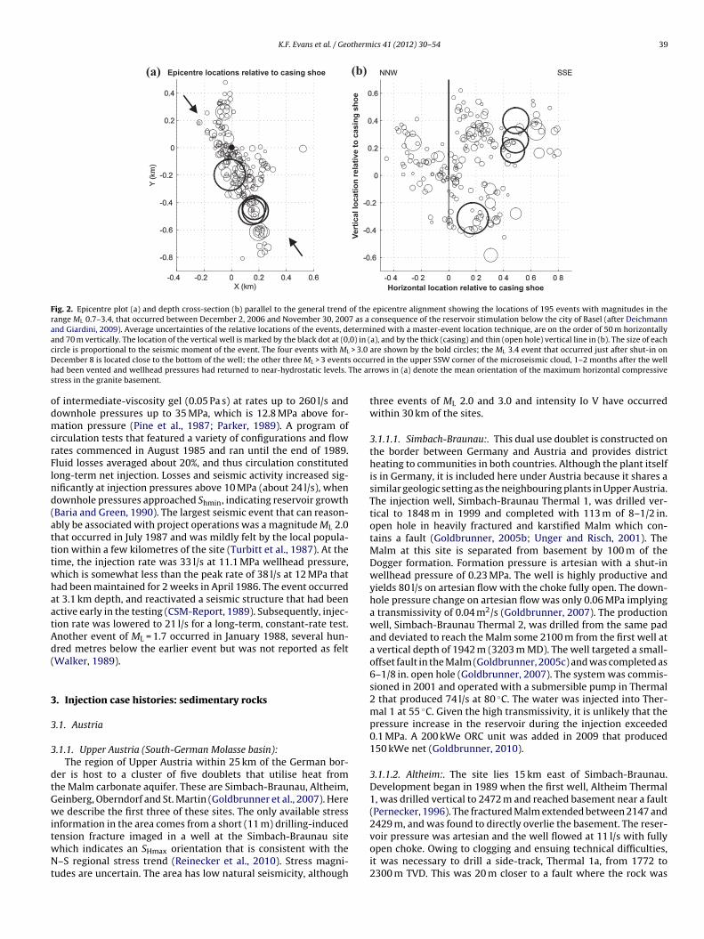
The hypocentre locations of 195 induced events that occurredsince the start of injection, and that were strong enough to berecorded by the surface network of the Swiss Seismological Ser-vice, are shown in Fig. 2. The overall hypocentre distribution definesa near-vertical lens-shaped cloud of 1.2 km diameter that strikesNNW–SSE and lies between 4 and 5 km depth. During injection,seismicity migrated away from the borehole, as would be expectedfor a diffusion-regulated process (see Fig. 6 of (Deichmann andGiardini, 2009)), and step-increases in flow rate/pressure tendedto increase event rate (Haering et al., 2008). After shut-in andbleed-off, seismic activity took place mainly at the periphery of thestimulated volume (Deichmann and Giardini, 2009). Fault planesolutions determined for the 28 strongest events are mostly purestrike-slip mechanisms with two pure normal faulting, and onea mixture of the two (Deichmann and Ernst, 2009). These focalmechanisms are largely in accord with the mechanisms of the natu-rally occurring regional seismicity. However, the strike of the nodalplanes of most of the events is oblique to the overall orientation ofthe seismic cloud. In fact, the focal mechanism of the ML 3.4 eventand its neighbours, together with the alignment of these events,suggest that failure occurred on a WNW–ESE striking, near-verticalplane (Deichmann and Ernst, 2009; Kahn, 2008). This suggests thatthe internal structure of the stimulated rock volume is composed ofa complex network of individual fault segments oriented obliquelyto the general trend of the microseismic cloud.
2.7. United Kingdom
2.7.1. Rosemanowes, Cornwall, UKThe Rosemanowes HDR project was active between 1978
and 1991, and culminated in the development and operationof a circulation system at a depth of ∼2 km within the Carn-menellis granite, which extends to the ground surface. Seismicactivity was monitored throughout operations with a surface net-work of 3-component accelerometers and occasionally a stringof hydrophones at reservoir depth (Batchelor et al., 1983). Thestress state is strike-slip and critical, the coefficient of the Coulombfriction strength law required to prevent failure at 2.0 km underambient conditions being 0.85 (Evans et al., 1992). The area has lownatural seismic hazard. The nearest events of note, which includea ML 3.5 event that occurred in 1981, are clustered near the townof Constantine, some 6 km south of the site (Turbitt et al., 1987).
Initially, two wells were drilled to 2050 m and stimulated with avariety of methods, including gel and water injections. For the mainwater stimulation, the wellhead pressure was 14 MPa and flow ratewas 90 l/s. Many tens of thousands of events of magnitude less thanML 0.16 were detected (derived from a moment of 1.8 × 10⁹ Nmgiven by Baria et al. (1985)). None were felt by the local popula-tion or the on-site project staff (CSM-Report, 1989; Turbitt et al.,1987). The seismic activity preferentially grew downward, which
is ascribed to the pore pressure increase required for shear failuredecreasing with depth (Pine and Batchelor, 1984).In 1985, a third well was drilled through the microseismic cloudto 2.65 km depth and stimulated with the injection of 5700 m3
K.F. Evans et al. / Geothermics 41 (2012) 30– 54 39
Epicentre locations relative to casing shoe
Horizontal location relative to casing shoe
(a) (b)
Fig. 2. Epicentre plot (a) and depth cross-section (b) parallel to the general trend of the epicentre alignment showing the locations of 195 events with magnitudes in therange ML 0.7–3.4, that occurred between December 2, 2006 and November 30, 2007 as a consequence of the reservoir stimulation below the city of Basel (after Deichmannand Giardini, 2009). Average uncertainties of the relative locations of the events, determined with a master-event location technique, are on the order of 50 m horizontallyand 70 m vertically. The location of the vertical well is marked by the black dot at (0,0) in (a), and by the thick (casing) and thin (open hole) vertical line in (b). The size of eachc > 3.0
D occuh The ars
odmcrFlnd(atttwhaatAd(
3
3
3
dtGwitwNt
ircle is proportional to the seismic moment of the event. The four events with ML
ecember 8 is located close to the bottom of the well; the other three ML > 3 eventsad been vented and wellhead pressures had returned to near-hydrostatic levels.
tress in the granite basement.
f intermediate-viscosity gel (0.05 Pa s) at rates up to 260 l/s andownhole pressures up to 35 MPa, which is 12.8 MPa above for-ation pressure (Pine et al., 1987; Parker, 1989). A program of
irculation tests that featured a variety of configurations and flowates commenced in August 1985 and ran until the end of 1989.luid losses averaged about 20%, and thus circulation constitutedong-term net injection. Losses and seismic activity increased sig-ificantly at injection pressures above 10 MPa (about 24 l/s), whenownhole pressures approached Shmin, indicating reservoir growthBaria and Green, 1990). The largest seismic event that can reason-bly be associated with project operations was a magnitude ML 2.0hat occurred in July 1987 and was mildly felt by the local popula-ion within a few kilometres of the site (Turbitt et al., 1987). At theime, the injection rate was 33 l/s at 11.1 MPa wellhead pressure,hich is somewhat less than the peak rate of 38 l/s at 12 MPa thatad been maintained for 2 weeks in April 1986. The event occurredt 3.1 km depth, and reactivated a seismic structure that had beenctive early in the testing (CSM-Report, 1989). Subsequently, injec-ion rate was lowered to 21 l/s for a long-term, constant-rate test.nother event of ML = 1.7 occurred in January 1988, several hun-red metres below the earlier event but was not reported as feltWalker, 1989).
. Injection case histories: sedimentary rocks
.1. Austria
.1.1. Upper Austria (South-German Molasse basin):The region of Upper Austria within 25 km of the German bor-
er is host to a cluster of five doublets that utilise heat fromhe Malm carbonate aquifer. These are Simbach-Braunau, Altheim,einberg, Oberndorf and St. Martin (Goldbrunner et al., 2007). Heree describe the first three of these sites. The only available stress
nformation in the area comes from a short (11 m) drilling-induced
ension fracture imaged in a well at the Simbach-Braunau sitehich indicates an SHmax orientation that is consistent with the–S regional stress trend (Reinecker et al., 2010). Stress magni-udes are uncertain. The area has low natural seismicity, although
are shown by the bold circles; the ML 3.4 event that occurred just after shut-in onrred in the upper SSW corner of the microseismic cloud, 1–2 months after the wellrows in (a) denote the mean orientation of the maximum horizontal compressive
three events of ML 2.0 and 3.0 and intensity Io V have occurredwithin 30 km of the sites.
3.1.1.1. Simbach-Braunau:. This dual use doublet is constructed onthe border between Germany and Austria and provides districtheating to communities in both countries. Although the plant itselfis in Germany, it is included here under Austria because it shares asimilar geologic setting as the neighbouring plants in Upper Austria.The injection well, Simbach-Braunau Thermal 1, was drilled ver-tical to 1848 m in 1999 and completed with 113 m of 8–1/2 in.open hole in heavily fractured and karstified Malm which con-tains a fault (Goldbrunner, 2005b; Unger and Risch, 2001). TheMalm at this site is separated from basement by 100 m of theDogger formation. Formation pressure is artesian with a shut-inwellhead pressure of 0.23 MPa. The well is highly productive andyields 80 l/s on artesian flow with the choke fully open. The down-hole pressure change on artesian flow was only 0.06 MPa implyinga transmissivity of 0.04 m2/s (Goldbrunner, 2007). The productionwell, Simbach-Braunau Thermal 2, was drilled from the same padand deviated to reach the Malm some 2100 m from the first well ata vertical depth of 1942 m (3203 m MD). The well targeted a small-offset fault in the Malm (Goldbrunner, 2005c) and was completed as6–1/8 in. open hole (Goldbrunner, 2007). The system was commis-sioned in 2001 and operated with a submersible pump in Thermal2 that produced 74 l/s at 80 ◦C. The water was injected into Ther-mal 1 at 55 ◦C. Given the high transmissivity, it is unlikely that thepressure increase in the reservoir during the injection exceeded0.1 MPa. A 200 kWe ORC unit was added in 2009 that produced150 kWe net (Goldbrunner, 2010).
3.1.1.2. Altheim:. The site lies 15 km east of Simbach-Braunau.Development began in 1989 when the first well, Altheim Thermal1, was drilled vertical to 2472 m and reached basement near a fault(Pernecker, 1996). The fractured Malm extended between 2147 and2429 m, and was found to directly overlie the basement. The reser-
voir pressure was artesian and the well flowed at 11 l/s with fullyopen choke. Owing to clogging and ensuing technical difficulties,it was necessary to drill a side-track, Thermal 1a, from 1772 to2300 m TVD. This was 20 m closer to a fault where the rock was
4 therm
mTThitawhat8aasw
3Enh(st2atGTawa(ubhTa(
3
aTsa(
sai2eb2htidoad(p
r
0 K.F. Evans et al. / Geo
ore fractured, which resulted in a higher artesian-flow of 18 l/s.his increased to 46 l/s after acid stimulation (Goldbrunner, 2005b).he well was operated under artesian drive and supplied a districteating system from 1991 to1998 (Goldbrunner, 2005c). Thereafter
t was decided to counter declining reservoir pressure by injectinghe spent fluid. In 1997 the injection well was drilled deviated to
vertical depth of 2165 m (3078 m MD). Very high permeabilitiesere encountered on entering the Malm, possibly indicating a faultad been intersected (Pernecker and Uhlig, 2002). Well separationt the top of the Malm is 1600 m (Goldbrunner, 2005b). In 2000,he production flow rate was increased to the operating level of1 l/s using a submersible electric pump in Altheim Thermal 1a,nd a 500 kW ORC unit was installed. The fluid is produced at 105 ◦Cnd reinjected into Thermal 2 at 70 ◦C and 1.7 MPa wellhead pres-ure (Goldbrunner, 2005b). The system supplies 10 MWt during theinter months and generates electricity during the summer.
.1.1.3. Geinberg (Austria):. This dual use project is located 5 kmNE of Altheim and has a developmental history similar to itseighbour. The first well was a vertical hydrocarbon explorationole drilled in 1976 that entered Malm at 2127 m, near a faultGoldbrunner, 1999), but was terminated at 2166 m due to exces-ive mud losses. The well was reopened and successfully deepenedo 2180 m in 1978 and became Geinberg Thermal 1 (Goldbrunner,005b). The well produced 22 l/s of fluid at more than 100 ◦C underrtesian drive and thereafter supplied a small district heating sys-em. The system was extended to a doublet in 1998 by drillingeinberg Thermal 2, partly to counter declining reservoir pressure.his was deviated to reach Malm at a vertical depth of 2225 m and
distance of 1600 m from the first well (Goldbrunner, 1999). Theell was completed with 276 m of open hole, mostly in Malm, and
fter an acid stimulation the productivity index was 1.0 l/s/MPaGoldbrunner, 1999). An injectivity test of Geinberg Thermal 1sing hot water produced from Thermal 2 showed that 30 l/s coulde injected at 0.2 MPa (Goldbrunner, 1999). The doublet systemas been in operation since late 1998, with 25 l/s produced fromhermal 2 at 105 ◦C under buoyancy drive (Karytsas et al., 2009),nd 21 l/s injected into Thermal 1 at 30 ◦C under gravity driveGoldbrunner, 2005b).
.1.2. Bad Blumau (Styrian basin of south-east Austria):This multiple use doublet is located some 50 km east of Graz
nd exploits heat from Paleozoic dolomites at a depth of ∼2.5 km.here are no published stress measurements within 45 km of theite. Whilst seismic hazard is low, two events of intensity Io VIre reported to have occurred within 40 km in the past 159 yearsGrünthal et al., 2009).
The injection well, Blumau 1a, was drilled as a steeply inclinedide-track from a hydrocarbon exploration well in 1995. It runspproximately parallel to and within 180 m of a WSW–ENE trend-ng growth fault with more than 1 km of throw (Goldbrunner,005a) and is completed in heavily fractured dolomites that arencountered at 2583 m TVD. These lie above phyllites that overlieasement rocks (Goldbrunner, 1999). The production well, Blumau, was drilled vertical to 2843 m and completed with 475 m openole in the fractured dolomites. The open-hole section lies betweenwo faults that cut the wellbore. Well separation at reservoir depths ∼1800 m (Goldbrunner, 2005a). Pumping tests in one well pro-uce perturbations in the other and imply a far-field transmissivityf 5 × 10⁻⁵ m2/s (Goldbrunner, 1999). Near-well transmissivitiesre much higher, thanks in part to an acid stimulation, and pro-uction flow rates of up to 80 l/s were obtained during tests
Goldbrunner, 1999). The water is rich in CO2, which aids ‘artesian’roduction through the gas-lift effect.The system began operation for heating usage in 1999 at a flowate of 30 l/s. Water is produced from Blumau 2 under artesian
ics 41 (2012) 30– 54
flow at a temperature of 110 ◦C. Almost all of the produced wateris injected into Blumau 1 at 50 ◦C or slightly greater temperatureyielding 7.6 MWt (Goldbrunner, 2005a). Injection pressure at thewellhead is less than 0.7 MPa (Goldbrunner, 2005b). Electricity gen-eration began in 2001 using a 250 kWe ORC unit (Legmann, 2003)to produce 180 kWe net (Goldbrunner, 2005a). The heating powerthen dropped to 5.1 MWt.
3.2. Denmark
3.2.1. Thisted:This district heating project is located in NW Jutland in the Dan-
ish basin. It exploits heat from the Upper Triassic Gassum sandstoneaquifer at 1.25 km depth that has a transmissibility of 10−10 m3
(Mahler, 1995). A large salt diapir structure exists immediately tothe NNW of the site (Mahler and Magtengaard, 2005), and so it ispossible that the sedimentary section is hydraulically decoupledfrom the basement. Unpublished analyses of borehole breakoutsin the injection well for the interval 804–1014 m reported in theWorld Stress Map database (Heidbach et al., 2010) indicate a meanSHmax orientation of N77◦E. Natural seismicity at the site is low.Only two documented historical events of estimated intensitiesIo V1 are recognised within 50 km, the nearest being 13 km away(Grünthal et al., 2009).
The project began in 1984 with the drilling of a 3287 m deepvertical exploration well, Thisted-2, which was plugged back to1273 m and a ∼37 m screen installed for production. The injectionwell of the doublet, Thisted-3, was drilled vertical to 1242 m andthe lowermost 50 m screened (Mahler, 1995). Well separation is1.5 km (Mahler and Magtengaard, 2005). The system was initiallycirculated at 10 l/s (Mahler and Magtengaard, 2010). In 1988, fol-lowing an improvement in the surface plant, the circulation ratewas increased to 41 l/s, yielding a total power of 4 MWt. The systemwas further upgraded to 7 MWt in 2001 by increasing the circula-tion rate to 56 l/s. The water is produced at 44 ◦C and cooled to 11 ◦Cbefore injection at a pressure of 1.7 MPa (Mahler and Magtengaard,2005).
3.2.2. Margretheholm (Copenhagen):The project supplies a district heating system from a doublet
completed in the Bunter formation at 2.5 km depth. No salt depositsare present between the Bunter and the Precambrian basement(Dong E&P, 2004). The natural seismicity in the area is low. Onlythree events with intensity Io V–VI are recognised as occurringwithin 50 km of the site since the 17th century (Grünthal et al.,2009).
The first exploration well of this project, Margretheholm-1,was drilled vertically to basement at 2677 m in 2002. Testingshowed the Bunter formation at 2.5–2.6 km had a productivity of22 l/s/MPa and was suitable for reservoir development (Mahler andMagtengaard, 2005). A second well, Margretheholm-2, was devia-tion drilled to 2745 m TVD in 2003 from the same pad so that wellseparation at reservoir depth was 1.3 km. Testing showed a produc-tivity of 17 l/s/MPa and communication with the first well (Mahlerand Magtengaard, 2010). The system began operation in late 2004.Water is pumped to surface at 65 l/s and 1.0–1.5 MPa by a down-hole pump (700 kW) at 650 m depth. It is cooled to 17 ◦C beforebeing injected at pressures up to 7.0 MPa (Mahler and Magtengaard,2010).
3.3. France
3.3.1. Paris basin (Paris):Exploitation of heat from carbonate units beneath Paris for space
heating began in the early 1970s and the system now is secondonly to Reykjavik (Iceland) in terms of size. The primary reservoir
therm
iTd82ai1riato
h2mtrs
3
3
mt
3lhs1aadmtfo2era
Ia(dNleN(diw2p0tta
wc
K.F. Evans et al. / Geo
s the mid-Jurassic Dogger aquifer composed of oolitic limestone.his is exploited over a large part of the eastern Paris region, atepths and temperatures ranging from 1450 to 2000 m and 56 to0 ◦C respectively (Ungemach and Antics, 2006; Ungemach et al.,005). Fifty-five doublets or triplets have been drilled of which 34re currently active (Lopez et al., 2010). The sedimentary sectionn the area is cut by N–S oriented normal faults (Cornet and Burlet,992). There are no reported stress measurements in the area. Theegional stress state is characterised by normal-to-strike-slip fault-ng with mean SHmax oriented approximately N145–150◦E (Cornetnd Burlet, 1992; Vidal-Gilbert et al., 2009). Natural seismicity inhe region is very low with no earthquakes reported within 50 kmf the centre of Paris.
Most well trajectories are deviated from a single drilling pad andave reservoir separations of about 1200 m (Ungemach and Antics,006). The average flow rates are 38–97 l/s, although operation ofost sites follows a seasonal cycle with peak flow rates in the win-
er (Lopez et al., 2010). Corresponding injection pressures usuallyange between 2.0 and 3.0 MPa with a maximum of 4.0 MPa at twoites (P. Ungemach, pers. comm., Oct 2010).
.4. Germany
.4.1. North-German BasinThere are several projects in this basin that mostly exploit
edium-enthalpy geothermal resources hosted in clastic forma-ions.
.4.1.1. Neustadt-Glewe/Waren/Neubrandenburg:. These plants areocated in the northeast of Germany and extract heat from theigh-porosity Rhätkeuper (Triassic) and Hettang (Jurassic) sand-tone aquifers at depths of 1.0–2.5 km. They were developed in the980s and were the first geothermal doublets in Germany (Seibtnd Kellner, 2003). Throughout the area, the sandstone aquifersre underlain by evaporites that include the extensive, thick salteposits of the Zechstein (Permian) (Seibt et al., 2005). The saltay hydraulically isolate and mechanically decouple the units of
he overlying section from the basement. Regional stress data fromormations below the salt indicate an approximately north–southrientation for SHmax and high deviatoric stress (Röckel and Lempp,003). The stress state in the overlying strata shows greater het-rogeneity (Röckel and Lempp, 2003). The natural seismicity in theegion is low with no recognised events located within 40 km ofny of the sites (Leydecker, 2009).
Neustadt-Glewe is the deepest and most westerly of the projects.t utilises the 40–60 m thick Contorta sandstone aquifer that has
porosity of 0.20–0.23 and a permeability of 0.5–1.0 × 10⁻¹² m2
Seibt et al., 2005). The fluid is produced at 99 ◦C from the 2455 meep well NG-1 and injected at 60 ◦C into the 2335 m deep wellG-2, which is separated by1500 m from NG-1. The static fluid
evels in the wells are about 125 m below ground level (Poppeit al., 2000). Acid and hydraulic stimulations were conducted onG-2 in 1993, but details of the treatments could not be located
Heederick, 1997). The system began supplying up to 6 MWt to theistrict heating system in 1995 and a 210 kWe ORC generator was
nstalled in 2003. The initial flow rate of 31 l/s could be injectedith a downhole overpressure of 0.5 MPa (Seibt and Wolfgramm,
008). However, occasional decreases in injectivity due to mineralrecipitation and particle clogging led to temporary increases to.8 MPa. These increases could be remedied with soft acidizationreatments, implying the increased impedance was localised nearhe well. Thus it is probable that the formation pressures in the
quifer beyond the immediate vicinity of the well were unaffected.Waren began supplying a district heating system in 1984, andas the first operational geothermal plant in Germany. The initial
onfiguration produced water from Contorta sandstone at 1560 m
ics 41 (2012) 30– 54 41
depth (reservoir temperature of 62 ◦C). The water was injected intothe Aalen sandstone at 1160 m depth through a well only 50 m dis-tant (Kabus and Jäntsch, 1995). The system was circulated at 14 l/susing a submersible pump. The wellhead pressure at the injectionwell reached 5 MPa (U. Reimer, pers. comm., Sept. 2010). In 1986 asecond injection well was drilled to 1580 m at a distance of 1.3 kmfrom the production well, and was screened in the Hettangian sand-stone, which lies just above the Contorta. Thereafter, the flow ratecould be increased to 17 l/s (Kabus and Jäntsch, 1995). Productiontemperature is 62 ◦C and injection temperature is no less than 45 ◦C(U. Reimer, pers. comm., Sept. 2010). Injection takes place undergravity drive. As the static water level in the injection well is 110 mbelow ground level, the downhole pressure change under injectionis less than 1.1 MPa (U. Reimer, pers. comm., Sept. 2010).
Neubrandenburg is the most easterly and shallowest of theprojects. In 1985 four boreholes were drilled to make two doubletsaccessing the Hettang and Postera sandstones, which are sandstoneunits above and below the Contorta respectively. The Postera pairwere N1 (production at 1250 m) and N3 (injection at 1250 m) wells,and the Hettang pair were N2 (production) and N4 (injection at1120 m) wells. The two injection wells were 5 m apart and had astatic water level of −62 m (U. Richlak, pers. comm., Sept. 2010). TheHettang production well N2 had technical problems. Thus, between1989 and 2001 the system was circulated at 19 l/s with produc-tion from well N1 (Postera) and injection into the 1.2 km distantwell pair N3 (Postera) and N4 (Hettang) at 0.5 MPa wellhead pres-sures (U. Richlak, pers. comm., Sept. 2010), implying a downholeoverpressure of 1.1 MPa. Production temperature was 54 ◦C.
In 2001, the system was reconfigured to allow waste-heatfrom gas-turbine electricity production in summer to be storedin the Postera reservoir and reused in the winter. Borehole N4(Hettang-injection) was deepened to reach the Postera, and theexisting Postera injection well, N3, was back-filled leaving a doublet(N1–N4) accessing the Postera. Operation of the thermal storagesystem began in April 2004. In summer, water is produced fromN4 at 28 l/s and 54 ◦C, heated to 80 ◦C with waste-heat from a gas-turbine generator, and the water injected into N1. In winter theflow is reversed with production from N1 at 28 l/s and 70–80 ◦C,and injection into N4 at ∼45 ◦C (Seibt et al., 2010). Wellhead injec-tion pressures are always less than 0.5 MPa implying a 1.1 MPadownhole overpressure (U. Richlak, pers. comm., Sept. 2010).
3.4.1.2. Gross Schönebeck. This pilot project located north of Berlinis designed to evaluate the possibility of using the EGS concept toextract heat from low-permeability sedimentary rocks. The reser-voir rocks are the sandstones and conglomerates of the Rotliegendformation and the volcanic rocks of the uppermost Carboniferous,all of which lie below the Zechstein salt layer. Hydraulic tests indi-cate a Shmin/SV ratio of 0.52 in the sandstones at 4150 m depth(Huenges et al., 2006), indicating that the stress state is criti-cal (Moeck et al., 2008). SHmax is oriented N18◦E (Zimmermannet al., 2008). Natural seismicity in the area is low, the closest eventbeing a ML 2.7 event at a distance of 50 km that occurred in 1736(Leydecker, 2009).
The largest volume injection tests were performed in 2003,after the first well (E GrSk3/90) was deepened to 4309 m. Some10,000 m3 of water was injected at rates up to 80 l/s and downholepressures that exceeded Shmin by up to ∼5 MPa. Most fluid enteredthe volcanics below the sandstones. A surface seismic networkconsisting of six 3-component stations in shallow boreholes wasoperational at the site during the injections, but detected no eventsattributable to fluid injection (M. Weber, pers. comm., Oct. 2010).
Subsequently, a second well (Gt GrSk4/05) was drilled and stim-ulation injections performed in the same formations, the largestinvolving the injection of 13,000 m3 of water and proppant intothe volcanic unit at rates of up to 150 l/s and wellhead pressures of
4 therm
5cradrhtt
3sttorii0t(csvgof
2d12dprs23stoh
3esTtB4lS
tiitidtwtad
2 K.F. Evans et al. / Geo
9 MPa (Zimmermann et al., 2008). Such volumes and flow rates areomparable to those used in the hydraulic stimulation of crystallineeservoirs. Seismic activity was monitored by the surface networkugmented by a downhole 3-component sensor placed at 3800 mepth in the first borehole. Only 70 events with magnitudes in theange ML −1.9 to −1.1 were detected, and then only by the down-ole sensor (Kwiatek et al., 2008). This low level of activity despitehe injection of large volumes at high pressure is consistent withhe growth of hydrofractures within the reservoir.
.4.1.3. Ketzin, Germany (CO2 injection):. This CO2 injection testite is located 40 km west of Berlin and is designed to monitorhe behaviour of CO2 injected into the Triassic Stuttgart forma-ion. Natural seismicity is very low, the nearest historical eventsf intensity Io IV or greater being more than 100 km distant. Theeservoir is an 80 m thick fluvial sandstone saline aquifer that hasts top at 630 m depth. It is highly heterogeneous, with porositiesn the range 0.05–0.35 (Norden et al., 2010), and permeabilities of.05–1.0 × 10⁻¹² m2 (Würdemann et al., 2010). The static forma-ion pressure is 6.3 MPa at 642 m, and the temperature is 35 ◦CWiese et al., 2010). Thus, the CO2 is a gas under formation PTonditions. The caprock consists of fine-grained, clay-rich clasticediments of the Weser Formation. Further containment is pro-ided by the Rupelian mudstone which served as the caprock to aas storage reservoir at depths of 250–400 m that was seasonallyperated from 1960s until 2000 (Juhlin et al., 2007). There are noaults within the CO2 reservoir (Juhlin et al., 2007).
The reservoir is penetrated by three vertical wells drilled in007: one 750 m deep injection well (Ktzi-201); and two 800 meep monitoring wells (Ktzi-200 and Ktzi-202) located 50 and00 m from the injector in orthogonal directions (Prevedel et al.,008). All three wells are instrumented with fibre-optic cables foristributed temperature sensing and supporting pointwise tem-erature and pressure measurements, and a 15 electrode verticalesistivity array (Prevedel et al., 2008). The CO2 is injected throughcreens at a depth of 650 m. CO2 injection commenced in June008 at a rate of about 2 ton/h which was gradually increased to
ton/h over 9 months. Pressure at the formation depth increasedteadily to 8.1 MPa after 1 year, which is 1.7 MPa above the forma-ion pressure (Würdemann et al., 2010). A seismic network has beenperational at the site since September 2009. No seismic eventsave been felt at the site (S. Lüth, pers. comm., March 2011).
.4.1.4. Horstberg. This is a geothermal pilot facility designed tovaluate the possibility of using single wells to extract heat fromediments in the North-German Basin (Wessling et al., 2009).he site is located north of Hannover, and the target produc-ion formations are low-permeability sandstone beds within theuntsandstein unit that lies above the Zechstein salt beds at about000 m depth (Orzol et al., 2005). Natural seismicity in the region is
ow, although a very rare event of magnitude ML 4.0 occurred nearoltau, some 26 km from the site in 1997 (Leydecker, 2009).
Massive water stimulations were performed through perfora-ions into several sandstone beds in 2003–2004. These injectionsnvolved volumes of up to 20,000 m3 and rates of 50 l/s. Wellheadnjection pressures of up to 32 MPa were higher than expected onhe basis of other injection operations in the area, possibly reflect-ng stress heterogeneity in the formations above the salt beds due tooming (Jung et al., 2005). Fluid from post-stimulation productionests was injected into the Kalkarenit formation at 1200 m depth,
hich is a karstic carbonate aquifer. The operations were moni-ored by an 8-station seismic array of 3-component sensors with detection threshold of magnitude ML 0. Only seven events wereetected, and all were too small to be located.
ics 41 (2012) 30– 54
3.4.2. South German–Austrian Molasse basinThis basin is host to numerous medium-enthalpy (100–140 ◦C)
geothermal projects. Most are centred on the Munich area(Schubert et al., 2007; Schulz et al., 2007), the remainder being dis-tributed over a wide area that extends into Austria (see Section3.1.1) (Goldbrunner et al., 2007). The majority of projects targetthe high-transmissibility zones within the Malm carbonate aquifer,which may be either karstic or fault-related, and many are dou-blets that involve injection. Productivities are high, and injectionand production pressures are typically less than a few MPa (Schulzet al., 2007). Stimulation operations tend to use acid rather thanhigh-rate hydraulic injections. For doublets, the production andinjection points within the Malm are two or more kilometres apart,and thus the flow field between the wells within the reservoir canbe complex, and may involve faults.
3.4.2.1. Straubing:. This site lies on the Danube some 10 km southof the Danube fault and 100 km northeast of Munich. It was oneof the first doublets to become operational in the basin. The near-est stress measurement in the World Stress Map (WSM) databaselies 60 km to the south and indicates a NS-orientation for SHmax(Reinecker et al., 2010). The area has low natural seismicity, nearestdocumented earthquake is located at a distance of 33 km and hadan intensity IO V (Leydecker, 2009). The production well, Therme I,was drilled vertical to 824 m depth in 1990 and entered fracturedand karstic Malm at 708 m. The well was artesian with a static well-head pressure of 0.41 MPa (Goldbrunner, 2007) and produced 29 l/sof water at 37 ◦C on unchoked flow. The second borehole, ThermeII, was drilled vertical to 885 m depth at a distance of 1680 m NNWof Therme 1 and penetrated Malm at 715 m, Dogger-age sandstoneand clay (Opalinus) at 842 m and crystalline basement at 863 m.Most of the discharge during drilling came from the Dogger sand-stone. Static wellhead pressure was 0.5 MPa. A production test witha downhole pump yielded 39 l/s with the water level at 203 m (pro-ductivity of ∼15 l/s/MPa), but only 5 l/s could be injected at 2.0 MPawellhead pressure (injectivity of 3.3 l/s/MPa) (Goldbrunner, 2007).To improve injectivity, the 9–5/8 in. well was plugged at 600 m,and an 8–1/2 in. diameter side-track was drilled towards a frac-ture zone that lay to the East. The casing shoe was set when theMalm was reached at 721.8 m TVD, and the hole continued as a6 in. with a sail angle of 77◦ to produce 339 m of open hole in theMalm (Goldbrunner, 2007). The initially poor injectivity was sig-nificantly improved by an acidization treatment with injection at22 l/s at up to 5.0 MPa. Venting produced significant quantities ofclastic material, presumably from the natural fractures that inter-sected the well. Following the treatment, 45 l/s could be injected ata wellhead pressure of 1.9 MPa (injectivity of 32 l/s/MPa). The sys-tem was commissioned in 1999 and operated with 21 l/s of waterproduced from Therme I at 36 ◦C and 19 l/s injected into ThermeIIa at 12 ◦C yielding 1.9 MWt for district heating. Later, the produc-tion flow rate was increased to 45 l/s of which 40 l/s was injected at14 ◦C at a wellhead pressure of 1.8 MPa. There are no reports of feltseismicity associated with this site during its 12 years of operation.
3.4.2.2. Munich area:. In the Munich area, the top of the Malm topdeepens from 1.6 km in the north to 3.5 km in the south, and the unitdirectly overlies the crystalline basement. The stress state in theMalm is strike-slip/thrust with SHmax oriented approximately N–S(Reinecker et al., 2010). No natural seismicity has been recordedwithin 40 km of Munich since records began to be kept in the 19thcentury. Formation pressure in the Malm is sub-hydrostatic, the
equilibrium water levels in the wells declining from 85 m belowground surface in the north to 250 m in the south. Since transmis-sibilities tend to be relatively high, the pressure increase aboveformation pressure in the injection wells at reservoir depth is in
therm
ap
ww(elbeMtSa2w
wi2shstddtfaailoicowwOm0b2(ldt2aeti(
3
oTk(iR
3lt
K.F. Evans et al. / Geo
ll cases less than 5.0 MPa under operational conditions (T. Fritzer,ersonal comm. December 2009).
The construction of doublets in the Munich area began in 2003ith the commissioning of the system at Unterschleissheim whichas soon followed by doublet systems at Riem (2004), Pullach
2005) and Unterhaching (2007) (Schubert et al., 2007; Wolfgrammt al., 2007). The operational parameters of these systems areisted in Table 1. The number of doublet and triplet systemsuilt or planned has accelerated since then, including the deep-st hydrothermal system in Europe at Sauerlach to the south ofunich, which will produce 140 ◦C water from 4.2 km depth for dis-
rict heating and electricity production in 2012 (Pletl et al., 2010).ystems commissioned after 2007 are not included in Table 1 tovoid introducing a local bias. Of the many projects in operation at012, the one at Unterhaching is located near an area with recent,eakly felt seismicity. Thus this project is described in detail.
At Unterhaching, the production (GT1a) and injection (GT2)ells have vertical depths of 3.35 and 3.59 km respectively and
ntersect the Malm at a vertical depth of 3.0 km (Wolfgramm et al.,007). The wells are 4 km apart at the Malm depth, and inter-ect different faults (E. Knapek, pers. comm., June 2010). The wellsave high injectivity/productivity, and pressure perturbations areeen to propagate between the wells in 24 h, presumably throughhe fault system (Wolfgramm et al., 2007). Under operational con-itions, the system to date has been circulated at 120 l/s, theownhole pressure excess above formation pressure in the injec-ion well at this rate being 2.5 MPa. The system began operationor district heating in October 2007 and electricity production wasdded in February 2009. In February 2008, 5 months after oper-tions began, an earthquake of magnitude ML 2.3 was detectedn this formerly aseismic region by the German Regional Seismo-ogical Network. The event was located within several kilometresf Unterhaching and was scarcely felt by the local population liv-ng within 5 km of the injection well GT2 (J. Wassermann, pers.omm., June 2010). A further three events of magnitude ML 2.1–2.4ccurred over a 3-week period in July 2008, the largest of whichas felt by the local population. In July 2008 a 3-station local net-ork was established in the area to improve the location accuracy.n 2nd February 2009, shortly after electricity production com-enced, a series of seven earthquakes of magnitudes between ML
.7 and 2.1 was detected by the local network (Kraft et al., 2009)ut none were felt by the local population (Bayerische-Landtag,009). No change in circulation parameters occurred at this timeE. Knapek, pers. comm., June 2010). Analysis of the data using aocal velocity model indicates that all hypocentres are located at aepth of 3.6 ± 1.5 km and some 0.5 ± 0.3 km west of the Gt-2a injec-ion interval, which lies at a vertical depth of 3.1–3.6 km (Kraft et al.,009). The larger events were also recorded by the national networknd found to have waveforms that were very similar to those of thearlier events, suggesting that all events occurred within 1 km ofhe open-hole section of the injection well (Kraft et al., 2009). Thenjection interval includes a fault with a vertical throw of 238 mWolfgramm et al., 2007).
.4.3. Upper Rhine GrabenThe graben hosts several projects at various stages of devel-
pment that seek to develop hydrothermal reservoirs in faultedriassic sandstone (Bundsandstein) and carbonate (Muschel-alk) units or the immediately underlying weathered basementBaumgärtner et al., 2006). The project at Landau exploits both sed-ments and basement and is described in Section 2, whereas that atiehen can be found in this section under Switzerland.
.4.3.1. Bruchsal, Germany. This dual use geothermal project isocated some 20 km northeast of Karlsruhe, on the eastern flank ofhe graben. It is one of the first geothermal projects in the graben,
ics 41 (2012) 30– 54 43
the first borehole being drilled in 1983. Unpublished boreholebreakout analyses for the geothermal site reported in the WorldStress Map database (Heidbach et al., 2010) indicate SHmax is ori-ented N130–140◦E. Stress magnitudes are uncertain. The site has alow seismic hazard level of 0.07 g, although 10 small events of mag-nitude ML up to 3.3 with intensities up to Io 5 have occurred within25 km of the site since 1970 (Leydecker, 2009). The largest histori-cal event within 30 km of the site is the 1948 Forchheim earthquakethat is 26 km distant and has been assigned a peak intensity of IoVII (Ahorner et al., 1970a).
An exploration borehole, GB1 was drilled vertical to 1932 m in1983 and discovered an exploitable reservoir in the lower Trias-sic Bunter and underlying Permian Rotliegend sandstones whichare cut by elements of the main boundary fault of the graben(Herzberger et al., 2010; Kölbel et al., 2010). In 1985, a second ver-tical well was drilled to 2450 m depth some 1400 m southwest ofthe first well to target the same formations (Kölbel et al., 2010). Thesystem was circulated for 6 weeks at up to 15 l/s in 1987, but tech-nical difficulties and economic considerations led to the suspensionof the project in 1990. It was reactivated in 2002 using the deeper,hotter well, GB2, as the production well. No hydraulic stimulationswere conducted. Static water levels in the wells were 60 m belowthe ground surface. A 550 kWe Kalina plant was installed in 2008and has been in operation since mid-2009. A pump in GB2 produceswater at a rate of approximately 24 l/s and a temperature of 118 ◦C.The cooled water is injected into GB1 under gravity producing anincrease in downhole pressure of approximately 0.5 MPa above thestatic pressure (Kölbel, 2010). There are no reports of felt micro-seismic events that can be ascribed to the operation of the system.A 4-station seismic monitoring network has recently been installedto detect and locate any induced microseismic events that are toosmall to be felt (Kölbel et al., 2010).
For Landau see Section 2.2.3, and for Riehen see Section 3.9.1.
3.5. Italy
3.5.1. Tuscan-Latium geothermal areas, ItalyThe region lies in western Italy between Rome and Pisa, and
includes several geothermal sites that have been explored and insome cases developed since 1970. The area is characterised by highgeothermal gradients, sometimes exceeding 100 ◦C/km, that reflectthe presence of shallow magmatic bodies. The tectonic settingis transcurrent/transtensional with predominant strike-slip fault-ing (Brogi and Fabbrini, 2009). The fields that have been exploredinclude Larderello-Travale and Monte Amiata in Tuscany, and Lat-era, Torre Alfina and Cesano in Latium. All fields except Cesano areassociated with significant natural seismicity (Batini et al., 1980b),suggesting that the reservoirs are likely to be critically stressed. Inthe 1970s, local seismic networks were installed at the sites in orderto systematically assess the seismic response of the various reser-voirs to fluid injection. In most cases the networks were installedprior to injection so that induced events could be distinguishedfrom the background. The networks were operated throughout theexploration phase (1977–1992) and remain active in those fieldsthat are still in production (Larderello-Travale and Monte Amiata).
3.5.1.1. Larderello-Travale. (Shown as “Larderello” in Fig. 1). Thisgeothermal area has long produced steam from folded anhydritesand carbonates that overlie metamorphic basement at a depth of2 km. In the early 1970s, injection of cold condensate from thepower plants was initiated in order to recharge the upper reser-voir, and a seismic monitoring network was installed, in part to
monitor the impact of the injection.The analyses of seismic data from 1978 to 1982 are presentedby Batini et al. (1980a, 1985). The area has a long history of seis-micity, and therefore many, if not most of the events are likely to
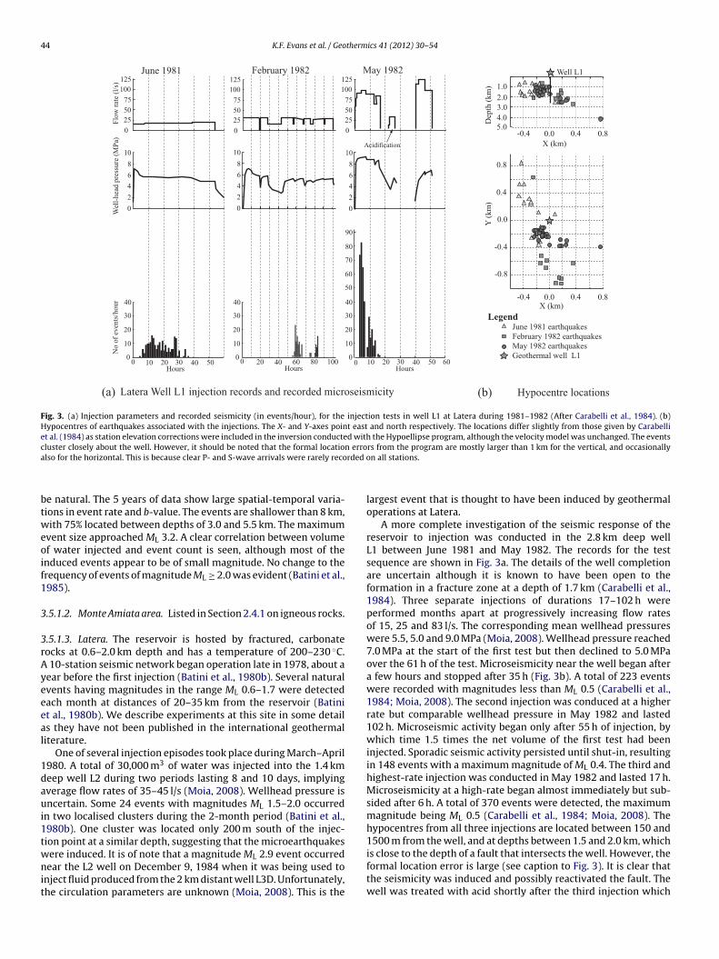
44 K.F. Evans et al. / Geothermics 41 (2012) 30– 54
0 10 20 30 40 50 60
Flow
rate
(l/s
)W
ell-h
ead
pres
sure
(MPa
)N
o of
eve
nts/
hour
10
20
30
40
0
10
20
30
40
60
50
70
80
90
00 10 20 30 40 50Hours Hours Hours
June 1981 May 1982February 1982
10
20
30
40
0
(b)(a) Latera Well L1 injection records and recorded microseismicity Hypocentre locations
X (km)
Y (k
m)
0.0
0.4
0.8
0.0
-0.4
-0.8
0.4-0.4 0.8
Legend June 1981 earthquakes February 1982 earthquakes May 1982 earthquakes Geothermal well L1
0.0 0.4-0.4 0.8
Well L1
1.02.03.04.05.0D
epth
(km
)
X (km)Acidification
2468
10
02468
10
02468
10
0
255075
100125
0255075
100125
0255075
100125
0
0 20 40 60 80 100
Fig. 3. (a) Injection parameters and recorded seismicity (in events/hour), for the injection tests in well L1 at Latera during 1981–1982 (After Carabelli et al., 1984). (b)Hypocentres of earthquakes associated with the injections. The X- and Y-axes point east and north respectively. The locations differ slightly from those given by Carabelliet al. (1984) as station elevation corrections were included in the inversion conducted with the Hypoellipse program, although the velocity model was unchanged. The eventsc n erroa rded o
btweoif1
3
3rAyeeeal
1daui1twnit
luster closely about the well. However, it should be noted that the formal locatiolso for the horizontal. This is because clear P- and S-wave arrivals were rarely reco
e natural. The 5 years of data show large spatial-temporal varia-ions in event rate and b-value. The events are shallower than 8 km,ith 75% located between depths of 3.0 and 5.5 km. The maximum
vent size approached ML 3.2. A clear correlation between volumef water injected and event count is seen, although most of thenduced events appear to be of small magnitude. No change to therequency of events of magnitude ML ≥ 2.0 was evident (Batini et al.,985).
.5.1.2. Monte Amiata area. Listed in Section 2.4.1 on igneous rocks.
.5.1.3. Latera. The reservoir is hosted by fractured, carbonateocks at 0.6–2.0 km depth and has a temperature of 200–230 ◦C.
10-station seismic network began operation late in 1978, about aear before the first injection (Batini et al., 1980b). Several naturalvents having magnitudes in the range ML 0.6–1.7 were detectedach month at distances of 20–35 km from the reservoir (Batinit al., 1980b). We describe experiments at this site in some details they have not been published in the international geothermaliterature.
One of several injection episodes took place during March–April980. A total of 30,000 m3 of water was injected into the 1.4 kmeep well L2 during two periods lasting 8 and 10 days, implyingverage flow rates of 35–45 l/s (Moia, 2008). Wellhead pressure isncertain. Some 24 events with magnitudes ML 1.5–2.0 occurred
n two localised clusters during the 2-month period (Batini et al.,980b). One cluster was located only 200 m south of the injec-ion point at a similar depth, suggesting that the microearthquakes
ere induced. It is of note that a magnitude ML 2.9 event occurredear the L2 well on December 9, 1984 when it was being used tonject fluid produced from the 2 km distant well L3D. Unfortunately,he circulation parameters are unknown (Moia, 2008). This is the
rs from the program are mostly larger than 1 km for the vertical, and occasionallyn all stations.
largest event that is thought to have been induced by geothermaloperations at Latera.
A more complete investigation of the seismic response of thereservoir to injection was conducted in the 2.8 km deep wellL1 between June 1981 and May 1982. The records for the testsequence are shown in Fig. 3a. The details of the well completionare uncertain although it is known to have been open to theformation in a fracture zone at a depth of 1.7 km (Carabelli et al.,1984). Three separate injections of durations 17–102 h wereperformed months apart at progressively increasing flow ratesof 15, 25 and 83 l/s. The corresponding mean wellhead pressureswere 5.5, 5.0 and 9.0 MPa (Moia, 2008). Wellhead pressure reached7.0 MPa at the start of the first test but then declined to 5.0 MPaover the 61 h of the test. Microseismicity near the well began aftera few hours and stopped after 35 h (Fig. 3b). A total of 223 eventswere recorded with magnitudes less than ML 0.5 (Carabelli et al.,1984; Moia, 2008). The second injection was conduced at a higherrate but comparable wellhead pressure in May 1982 and lasted102 h. Microseismic activity began only after 55 h of injection, bywhich time 1.5 times the net volume of the first test had beeninjected. Sporadic seismic activity persisted until shut-in, resultingin 148 events with a maximum magnitude of ML 0.4. The third andhighest-rate injection was conducted in May 1982 and lasted 17 h.Microseismicity at a high-rate began almost immediately but sub-sided after 6 h. A total of 370 events were detected, the maximummagnitude being ML 0.5 (Carabelli et al., 1984; Moia, 2008). Thehypocentres from all three injections are located between 150 and1500 m from the well, and at depths between 1.5 and 2.0 km, which
is close to the depth of a fault that intersects the well. However, theformal location error is large (see caption to Fig. 3). It is clear thatthe seismicity was induced and possibly reactivated the fault. Thewell was treated with acid shortly after the third injection which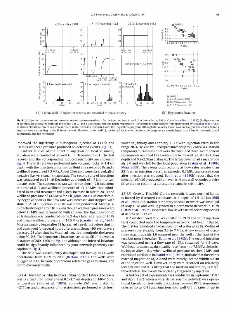
K.F. Evans et al. / Geothermics 41 (2012) 30– 54 45
0 5 10 15 20 25
0Wel
l-hea
d pr
essu
re (M
Pa)
No.
eve
nts/
hour
4
8
0 10 20 30 40 50 60 700 5 10 15 20Hours
1-2 December 1981 21-22 December 198118-19 December 1981
Acidification
begin 17:00on 1.12.81
end 9:00on 2.12.81
Max pressure =14.2 MPa
HoursHours
begin 16:00on 21.12.81
end 11:00on 22.12.81
begin 6:00on 18.12.81
end 8:00on 19.12.81
20
0
40
60
Flow
rate
(l/s
)20
0
40
60
20
0
40
60
12
16
0
4
8
12
16
10
20
30
40
0
10
20
30
40
0
10
20
30
40
0
(a) Latera Well L6 injection records and recorded microseismicity Hypocentre locations(b)
1-2 December 1981
21-22 December 198118-19 December 1981
X (km)
Y (k
m)
0.0
0.0
-0.4
-0.6
-0.2
-0.8
-1.0
-1.2
0.2-0.2 0.4 0.6 0.8 1.0 1.2
Well L6
Well L6
1.02.03.04.05.0D
epth
(km
)
X (km)0.0 0.2-0.2 0.4 0.6 0.8 1.0 1.2
1.4 km depth volcanics1.4 km depth volcanics 1.7 km depth carbonates 1.7 km depthcarbonates
Fig. 4. (a) Injection parameters and recorded seismicity (in events/hour), for the injection tests in well L6 at Latera during 1981 (after (Carabelli et al., 1984)). (b) Hypocentresof earthquakes associated with the injections. The X- and Y-axes point east and north respectively. The locations differ slightly from those given by Carabelli et al. (1984)a Hypol rmal lo
i6
arFdwnwbanwismb2aMadbdcc
opn
3vt∼
s station elevation corrections were included in the inversion conducted with theinear structure extending to the SE from the well. However, as for well L1, the foccasionally also the horizontal.
mproved the injectivity. A subsequent injection at 111 l/s and.0 MPa wellhead pressure produced no detected events (Fig. 3a).
Further studies of the effect of injection on local seismicityt Latera were conducted in well L6 in December 1981. The testecords and the corresponding induced seismicity are shown inig. 4. The first test was performed into volcanic rocks at 1.4 kmepth with the injection of formation fluid at a rate of 66 l/s and aellhead pressure of 7.5 MPa. About 20 events were observed, all ofegative (i.e. very small) magnitude. The second suite of injectionsas conducted on 18–19 December at a depth of 1.7 km into car-
onate rocks. The sequence began with three short ∼2 h injectionst a rate of 8 l/s and wellhead pressure of 13–14 MPa that culmi-ated in an acid treatment and a step-increase in rate to 28 l/s andellhead pressure of 14.5 MPa for 1 h (Moia, 2008). Microseismic-
ty began as soon as the flow rate was increased and stopped withhut-in. A 24 h injection at 28 l/s was then performed. Microseis-ic activity began after 10 h, even though wellhead pressures were
elow 13 MPa, and terminated with shut-in. The final injection of0 h duration was conducted some 2 days later at a rate of 40 l/snd mean wellhead pressure of 14.5 MPa (Carabelli et al., 1984).icroseismicity began after 11 h, reached a peak just before shut-in
nd continued for several hours afterwards. Some 196 events wereetected, 28 after shut-in. Most had negative magnitude, the largesteing ML 0.8. The hypocentre locations lay to the SE of the well atistances of 200–1500 m (Fig. 4b), although the inferred locationsould be significantly influenced by poor network geometry (seeaption to Fig. 4).
The field was subsequently developed and had up to 14 wellsperational from 1999 to 2003 (Bertani, 2005). The wells werelugged in 2008 because of problems related to gas emissions, andot to microseismicity.
.5.1.4. Torre Alfina. This field lies 10 km north of Latera. The reser-oir is a fractured limestone at 0.5–1.7 km depth and 140–150 ◦Cemperature (Billi et al., 1986). Borehole RA1 was drilled to2710 m and a sequence of injection tests performed with fresh
ellipse program, although the velocity model was unchanged. The events define aocation errors from the program are mostly larger than 1 km for the vertical, and
water in January and February 1977 with injection rates in therange 20–40 l/s and wellhead pressures of up to 1.2 MPa. A 4-stationtemporary microseismic network that included three 3-componentinstruments recorded 177 events close to the well (i.e. at 1.4–3.3 kmdepth and 0.2–2.0 km distance). The largest event had a magnitudeML 3.0 and was felt by the local population (Batini et al., 1980b;Moia, 2008). The events occurred only at flow rates greater than25 l/s when injection pressures exceeded 0.7 MPa, and ceased soonafter injection was stopped. Batini et al. (1980b) report that theinjection of fluid produced from well A14 into well A4 under gravitydrive did not result in a detectable change in seismicity.
3.5.1.5. Cesano. This 250 ◦C brine reservoir, located north of Rome,is hosted by fractured carbonates at a depth of 1.5–3.0 km (Billiet al., 1986). A 5-station temporary seismic network was installedin May 1978 and was upgraded to a permanent network in 1979(Batini et al., 1980b). Dispersed, low-level natural seismicity occursat depths of 6–12 km.
A 2 km deep well RC-1 was drilled in 1978 and short injectiontests conducted once the temporary network had been installed.The first test involved a 1-day injection of water at 28 l/s. Wellheadpressure rose steadily from 3.5 to 7 MPa. A few events of maxi-mum magnitude ML 1.6 occurred near the well at the start of thetest, but none thereafter (Batini et al., 1980b). The second injectionwas conducted using a flow rate of 15 l/s sustained for 1.5 days.Wellhead pressure again steadily rose from 4 to 7.5 MPa. Seismic-ity began after 1 day when wellhead pressure reached 7 MPa andcontinued until shut-in. Batini et al. (1980b) indicate that the eventsreached magnitude ML 2.0 and were mostly located within 400 mof the injection well. However, they were recorded on relativelyfew stations and it is likely that the location uncertainty is large.Nevertheless, the events were clearly triggered by injection.
A further set of experiments was conducted in September 1981and April 1982 when a very dense seismic network was opera-tional. Circulation tests with production from well RC-1 (sometimesreferred to as C-1) and injection into well C-5 at rates of up to
4 therm
4b
afhidAciar
3
3
oDTw(aaa1
bdKtta41essbbmp2oaiabIo
3
3
gSsaftSomt
6 K.F. Evans et al. / Geo
2 l/s under gravity drive produced no seismic events that coulde identified as triggered by injection (Cameli et al., 1983).
To summarise the results for the Tuscan-Latium geothermalreas, the impact of injection on seismicity at the various sites is asollows: the effect at Monte Amiata is difficult to assess because ofigh background seismicity (see Section 2); at Larderello-Travale,
njection enhances the number of small-magnitude events butoes not detectably affect the large-magnitude events; at Torrelfina, Latera and Cesano, dedicated injection experiments yieldedlear examples where injection has induced seismicity up to andncluding magnitude ML 3.0. However, the injection experimentslso yielded examples where injection produced negligible seismicesponse.
.6. Lithuania
.6.1. Klaipeda:This district heating project is located on the Baltic Sea coast. The
bjective was to produce 167 l/s of water at ∼40 ◦C from a Lowerevonian Viesvile formation at depths between 990 and 1118 m.he unit consists of sandstone of porosity 0.2–0.3 interspersedith clay-rich packets, and has a permeability of 0.2–6.2 × 10⁻¹² m2
Zinivicius et al., 2003). The basement lies at about 2200 m. Therere no published stress measurements within 50 km of the site. Therea has low natural seismic hazard. The nearest event in the cat-logue of Grünthal et al. (2009) is a Mw 4.2 event at a distance of00 km.
Construction on the system began in 1996. Initially two neigh-ouring vertical production wells KGDP-2P and KGDP-3P wererilled to 1128 and 1225 m respectively, and one injection well,GDP-1I was drilled to 1228 m at a distance of 800–1000 m from
he production wells (Zinivicius et al., 2003). However, it was foundhat the injectivity of the well was insufficient to dispose of fluidt the desired rate of 167 l/s at the maximum injection pressure of.0 MPa. Therefore, a second injection well, KGDP-I4, was drilled to128 m depth even further from the production wells (Ziniviciust al., 2003). All wells are completed with 9–5/8 in. casing andcreened between 1028 and 1128 m. The fluid has 95 g/l dissolvedolids and low gas content. The system began operation in 2001ut capacity declined because of decreasing injectivity, primarilyecause of mineral precipitation in the surface lines, well and for-ation (Seibt and Wolfgramm, 2008). Periodic remedial operations
roduced only temporary improvement (Seibt and Wolfgramm,008). System operation was suspended in 2007 to perform a majorverhaul because flow rate had dropped from 97 to 39 l/s (Ziniviciusnd Sliupa, 2010). Operation resumed in November 2008 withnjection rate into KGDP-I4 increasing from 30 to 50 l/s (Ziniviciusnd Sliupa, 2010). Injection pressures during operation could note determined but presumably approach the design limit of 4 MPa.
nformation is unavailable as to whether a seismic network wasperational and whether any earthquakes were felt.
.7. Norway
.7.1. Sleipner, North Sea, Norway (CO2 injection):This is a pioneering project of Statoil to remove CO2 from natural
as produced from the Sleipner-Vest gas reservoir underlying theleipner-A platform in the North Sea and inject it into the exten-ive, high-permeability, 200 m thick Utsira saline aquifer that lies at
depth of 800–1100 m (Torp and Gale, 2004). The Sleipner-A plat-orm is located near the eastern margins of the southern part ofhe Viking Graben, which is characterised by moderate seismicity.
everal events of magnitude ML 2–3 have occurred within 50 kmf the platform over the past 20 years (ISC, 2010). The Utsira for-ation is a hydrostatically-pressured, unconsolidated sandstonehat has an estimated porosity of 35–40% and a permeability of
ics 41 (2012) 30– 54
1–8 × 10⁻¹² m−12 (Baklid and Korbøl, 1996; Torp and Brown, 2005).The well entered the Utira formation at 872 m true vertical depth(TVD), and was deviated so that the injection point is approximately3 km away from the platform complex. The lowermost 1365 m iscompleted sub-horizontal with 7 in. liner to 1086 m TVD, and is per-forated over a 138 m interval centred at 1015 m TVD (Hansen et al.,2005). At the P–T conditions of the Utsira, the CO2 is expected to bein the supercritical phase, which is supported by seismic and grav-ity measurements (Zumberge et al., 2006). Injection began in 1996at a rate of 1 Mton/year, or an average of 32 kg/s. The CO2 is injectedat a wellhead temperature of 25 ◦C and a pressure 6.2–6.4 MPa,and is thus close to the liquid/gas phase boundary (Hansen et al.,2005; Eiken et al., 2011). Consequently, downhole injection pres-sure above hydrostatic is uncertain (O. Eiken, pers. comm., April2011). The tables produced by Baklid and Korbøl (1996) suggesta value of 3.5 MPa above hydrostatic pressure. This is probablyan upper bound: other evidence suggests pressure may be onlymarginally above hydrostatic (Eiken et al., 2011). Possible localseismic activity is not monitored at the site. However, there is noevidence from the regional networks of seismicity associated withthe CO2 injection operations (T. Torp, pers. comm., March 2011).
3.8. Poland
3.8.1. Bialy-Dunajec/Banska (Podhale basin):The geothermal plant in the basin is located near Banska where
a doublet began operation in 1992. This was expanded to a 4-wellsystem in 2001, primarily for heating. The reservoir is a heav-ily fractured, karstified, overthrust Triassic carbonate overlain bypost-tectonic, Eocene nummilitic-limestone at depths of 2–3 km(Kêpinska, 2000). The boreholes lie close to the major lineamentof the Bialy-Dunajek fault, which contributes to the high degree offracturing (Kêpinska, 2000; Wieczorek, 1999). The area has moder-ate seismic activity. Events of intensities up to Io V–VI are commonwithin 50 km of the site, with occasional but rare events with inten-sities up to Io VII. Intensity distributions show that at least someevents occur above the basement at depths of a few kilometres(Guterch et al., 2005). An earthquake of magnitude MW 4.5 that pro-duced intensities up to Io 7.0 occurred only several kilometres fromthe site in 2004 (Wiejacz and Debski, 2009). The focal mechanismof the event indicates normal faulting with Shmin oriented approx-imately WNW to NW (Wiejacz and Debski, 2009). The proximityof the event to the site suggests the stress state in the area is criti-cal. The relationship of the earthquake to geothermal operations isunclear as there was no local seismic network.
The production well of the initial doublet, Banska IG-1, wasan exploration borehole drilled to 5261 m in 1981. The well wascompleted in the Triassic/Eocene carbonates by perforating overthe interval 2588–2683 m. Static wellhead pressure was 2.7 MPa,and unchoked artesian-outflows of 17 l/s were obtained (Kêpinska,2003c). The injection well of the doublet, Bialy Dunajec PAN-1,was drilled 1220 m distant from the producer in 1989, and wascompleted in the same unit between 2117 and 2394 m (Kêpinska,2003a). Static wellhead pressure was 2.4 MPa. The doublet wasoperated between 1992 and 2001 at flow rates up to 17 l/s and injec-tion wellhead pressures up to 2.5 MPa (B. Kêpinska, pers. comm.,Oct. 2010). Production temperature was up to 80 ◦C and injectiontemperatures were no less than 50 ◦C (Bujakowski, 2000).
In 2001 the capacity of the system was increased by adding anadditional production and an injection well. These were drilled intothe same formations at locations near the existing wells giving a
pair of injection and a pair of production wells 1.2–1.7 km apart.The second production well, Banska PGP-1, was highly produc-tive and discharged 152 l/s of fluid at 87 ◦C under artesian drive.The second injection well, Bialy Dunajec PGP-2, required 8.4 MPa
therm
wbTiwoiae3
3
oTedo1isnt
iS221a5Ttwit(waT0
3
3
gtostsstsiat
4
tdtb
K.F. Evans et al. / Geo
ellhead pressure to inject 45 ◦C water at 56 l/s (Kêpinska, 2003c),ut this was reduced to 5.0 MPa by acid stimulation (Nagy, 2007).he 4-well system began operation at a peak flow rate of 186 l/sn 2001. The maximum wellhead pressure at both injection wells
as 6.0 MPa (Kêpinska, 2003c). Given a static wellhead pressuref 2.4 MPa, negligible friction losses in the 9–5/8 in. casing, and anncrease in column weight due to cooling of about 0.2 MPa (Dlugosznd Nagy, 1995), the corresponding maximum downhole pressurexcess above formation pressure during injection is approximately.8 MPa.
.8.2. Uniejów (Polish Lowlands):The town lies in the Polish Lowland Province, some 50 km WNW
f Lodz. It is located on the southern margin of the Mid-Polishrough, which is a major continental suture (Dadlez, 2003; Dadlezt al., 1995). The reservoir is a Lower Cretaceous sandstone at aepth of 1.9–2.0 km (Kêpinska, 2010). The basement lies at depthsf 5–6 km and is overlain by Zechstein salt deposits (Dadlez et al.,995). The nearest stress estimate registered in the WSM database
s from a site some 150 km away. Regional data are reasonably con-istent in indicating a pattern of NS compression. The area has lowatural seismic hazard. The nearest events are located some 110 kmo the east and have magnitudes in the range Mw 4.2–4.6.
The injection (AGH-1) and production (AGH-2) wells of thenitial doublet were drilled 1 km apart in 1990–1991 (Sapínska-líwa, 2003). The reservoir temperature was 70 ◦C (Kêpinska et al.,000), and the static wellhead pressure was 0.4 MPa (Kêpinska,003b). Production flow rate from AGH-2 under artesian drive was8.8 l/s at 68 ◦C but could be increased to 33.4 l/s with the aid of
submersible pump (Kêpinska, 2010). Total dissolved solids were–8 g/l. The doublet was commissioned for district heating in 2001.he operational flow rate in 2004 was 18.8 l/s at 68 ◦C, with injec-ion at 42 ◦C giving 2.1 MWt (Kêpinska, 2005). Injection pressureas 0.7 MPa (Sapínska-Slíwa, 2003). The system was expanded
n 2005 with the addition of a second injection well, IGH-1, andhe installation of a submersible pump in the production wellSapínska-Slíwa and Gonet, 2010). The peak flow rate in winteras 28 l/s at a temperature of 69 ◦C with injection temperature of
t most 45 ◦C yielding 2.75 MWt (Sapínska-Slíwa and Gonet, 2010).he injection pressures of the 3-well system were approximately.6–0.7 MPa (Sapínska-Slíwa et al., 2010).
.9. Switzerland
.9.1. Riehen, SwitzerlandThis hydrothermal doublet is located at the southern end of the
raben, some 5 km east of the Basel EGS site. The locality is charac-erised by moderate levels of natural seismicity (see Section 2.6.1n Basel EGS). The system consists of two boreholes drilled to inter-ect the Muschelkalk carbonate at a depth of 1.25–1.55 km wherehey are 1 km apart (Mégel and Rybach, 2000). This geologic unit iseparated from the basement by thick anhydrite beds and possiblyalt that might serve to hydraulically isolate the pore pressure dis-urbance in the reservoir from the basement (Hauber, 1991). Theystem has been in balanced operation at a flow rate of 18 l/s andnjection wellhead pressure of less than 1.5 MPa since 1989. Therere no reports of felt seismicity associated with the operation ofhis dual use (electricity/district heating) plant.
. Discussion
The primary objective of this study is to document case his-
ories of fluid injection with a view to identifying any systematicependence of the seismic response on reservoir injection depth orhe various parameters that constitute ‘geological setting’. It muste recognised from the outset that the available data are not idealics 41 (2012) 30– 54 47
in this regard. Injections that involve a net fluid volume increasewithin the reservoir such as in hydraulic stimulation operationswould, in principle, produce a greater disturbance of pressure in thereservoir and its surroundings than comparable injections that arebalanced by production from the same reservoir, as is the case withmost operating geothermal plants. These cases are distinguishedin Table 1. Even allowing for this, the data are too heterogeneousand too few in number to allow firm conclusions to be drawn onthe basis of single-parameter correlation with seismic response.Multi-parameter correlations such as examining simultaneouslythe dependence of seismic response on depth and volume injectedare probably more appropriate but require more data than the 41sites included here. A further limitation arises from the absence oflocal seismic networks at most sedimentary injection sites. In thesecases, all that is known about the seismic response is whether or nota felt event was generated. In contrast, most igneous injection sitesincluded in the study are EGS sites where seismic networks wereoperational, and thus exact measures of the maximum magnitudeof the induced earthquakes are available.
The index of natural seismic activity adopted in this paper isthe local peak ground acceleration value that has a 10% chanceof being locally exceeded in 50 years, and is denoted as PGA inTable 1 (Giardini et al., 1999). The map of PGA values for West-ern Europe is shown with site locations in Fig. 1. A comparison ofthe maximum magnitudes triggered by fluid injection and the localPGA value is shown in Fig. 5 for igneous and sedimentary sites. Theboundary between low and moderate hazard is taken by Giardiniet al. (1999) as 0.08 g. Although this is somewhat arbitrary, it willbe seen to have some utility. The threshold magnitude for an earth-quake to be felt is taken as ML 2.0, which is the magnitude found forevents in the 5 km reservoir at Soultz to be felt by the local popu-lation (N. Cuenot, pers. comm., May 2010). This corresponds to theboundary between ‘microearthquake’ and ‘earthquake’ proposedby Bohnhoff et al. (2010), although this is also somewhat arbitrary.Thus, the maximum possible magnitude of induced events at siteswithout a local seismic network, and where seismicity was not feltor recorded on regional networks, was set at 2.0. These sites areindicated in Fig. 1 by the ‘error bar’ extending down from ML 2.0 toindicate the range of possible values. The multiplicative factor indi-cates the number of sites that are superposed. Sites where an exactvalue is available for the maximum magnitude of induced eventsare shown by filled circles.
It is evident that there is no simple correlation between the PGAindex of natural seismicity at a site and the maximum ML induced inresponse to injection, either for igneous or sedimentary rocks. Forigneous rocks, where the trends are clearer owing to the availabilityof exact measures of max-ML, all felt events occurred at sites wherethe PGA value was 0.08 g or greater. Most igneous cases denotestimulation injections. Two Icelandic sites at Laugaland and Svart-sengi have relatively high PGA values, but showed very low seismicresponse to injection. This is probably because both involved injec-tion into reservoirs whose pressure had declined by a few MPaowing to earlier production (Brandsdóttir et al., 2002). For injec-tion into sedimentary rocks, only four out of 25 cases produced feltevents, and three of these have PGA values substantially greaterthan 0.07 g. There are three sites where local PGA values exceed0.07 g but no felt events were initiated by the injections, althoughone of these, Cesano, is marginal in as much as an event of ML 2.0was recorded. The other two cases are Riehen in Switzerland, wherethere are evaporites below the reservoir that might inhibit pressurediffusion into the basement, and Bialy-Dunajek in Poland.
The only exception to the rule, based on the current admittedly
limited data, that sites with felt events have PGA values higher than0.07 g is the Unterhaching site where an event of ML 2.4 occurredduring operation despite the area having an expected PGA of 0.05 g.At Unterhaching, injection takes place into a high-angle fault in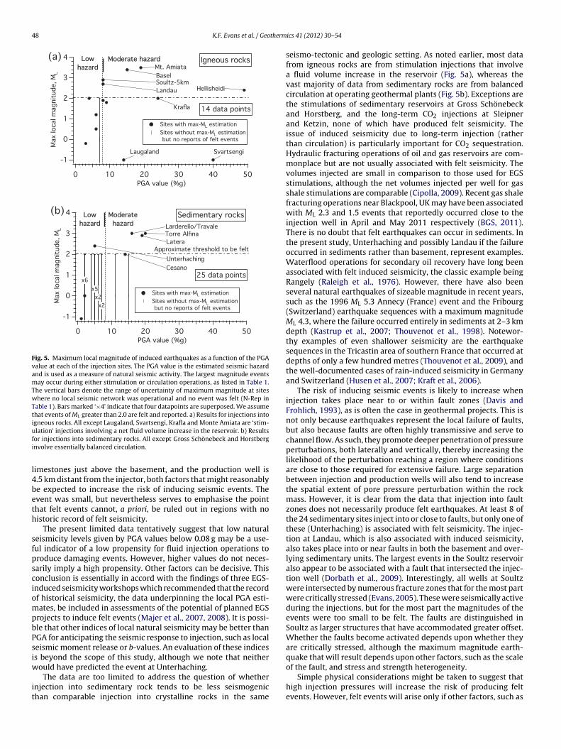
48 K.F. Evans et al. / Geotherm
4
3
2
1
0
-1
Max
loca
l mag
nitu
de, M
L
50403020100PGA value (%g)
Igneous rocks
BaselSoultz-5km
Lowhazard
Moderate hazard
Sites with max-ML estimation Sites without max-ML estimation
but no reports of felt events
Landau Hellisheidi
Mt. Amiata
14 data points
SvartsengiLaugaland
Krafla
4
3
2
1
0
-1
Max
loca
l mag
nitu
de, M
L
50403020100PGA value (%g)
Sedimentary rocks
Approximate threshold to be felt
Lowhazard
Moderatehazard
Unterhaching
Latera
Sites with max-ML estimation Sites without max-ML estimation
but no reports of felt events
Torre AlfinaLarderello/Travale
Cesano
x6x5
25 data points
x2x2
(a)
(b)
Fig. 5. Maximum local magnitude of induced earthquakes as a function of the PGAvalue at each of the injection sites. The PGA value is the estimated seismic hazardand is used as a measure of natural seismic activity. The largest magnitude eventsmay occur during either stimulation or circulation operations, as listed in Table 1.The vertical bars denote the range of uncertainty of maximum magnitude at siteswhere no local seismic network was operational and no event was felt (N-Rep inTable 1). Bars marked ‘×4’ indicate that four datapoints are superposed. We assumethat events of ML greater than 2.0 are felt and reported. a) Results for injections intoigneous rocks. All except Laugaland, Svartsengi, Krafla and Monte Amiata are ‘stim-ufi
l4beth
sfpsciompbPsiw
it
lation’ injections involving a net fluid volume increase in the reservoir. b) Resultsor injections into sedimentary rocks. All except Gross Schönebeck and Horstbergnvolve essentially balanced circulation.
imestones just above the basement, and the production well is.5 km distant from the injector, both factors that might reasonablye expected to increase the risk of inducing seismic events. Thevent was small, but nevertheless serves to emphasise the pointhat felt events cannot, a priori, be ruled out in regions with noistoric record of felt seismicity.
The present limited data tentatively suggest that low naturaleismicity levels given by PGA values below 0.08 g may be a use-ul indicator of a low propensity for fluid injection operations toroduce damaging events. However, higher values do not neces-arily imply a high propensity. Other factors can be decisive. Thisonclusion is essentially in accord with the findings of three EGS-nduced seismicity workshops which recommended that the recordf historical seismicity, the data underpinning the local PGA esti-ates, be included in assessments of the potential of planned EGS
rojects to induce felt events (Majer et al., 2007, 2008). It is possi-le that other indices of local natural seismicity may be better thanGA for anticipating the seismic response to injection, such as localeismic moment release or b-values. An evaluation of these indicess beyond the scope of this study, although we note that neither
ould have predicted the event at Unterhaching.The data are too limited to address the question of whether
njection into sedimentary rock tends to be less seismogenichan comparable injection into crystalline rocks in the same
ics 41 (2012) 30– 54
seismo-tectonic and geologic setting. As noted earlier, most datafrom igneous rocks are from stimulation injections that involvea fluid volume increase in the reservoir (Fig. 5a), whereas thevast majority of data from sedimentary rocks are from balancedcirculation at operating geothermal plants (Fig. 5b). Exceptions arethe stimulations of sedimentary reservoirs at Gross Schönebeckand Horstberg, and the long-term CO2 injections at Sleipnerand Ketzin, none of which have produced felt seismicity. Theissue of induced seismicity due to long-term injection (ratherthan circulation) is particularly important for CO2 sequestration.Hydraulic fracturing operations of oil and gas reservoirs are com-monplace but are not usually associated with felt seismicity. Thevolumes injected are small in comparison to those used for EGSstimulations, although the net volumes injected per well for gasshale stimulations are comparable (Cipolla, 2009). Recent gas shalefracturing operations near Blackpool, UK may have been associatedwith ML 2.3 and 1.5 events that reportedly occurred close to theinjection well in April and May 2011 respectively (BGS, 2011).There is no doubt that felt earthquakes can occur in sediments. Inthe present study, Unterhaching and possibly Landau if the failureoccurred in sediments rather than basement, represent examples.Waterflood operations for secondary oil recovery have long beenassociated with felt induced seismicity, the classic example beingRangely (Raleigh et al., 1976). However, there have also beenseveral natural earthquakes of sizeable magnitude in recent years,such as the 1996 ML 5.3 Annecy (France) event and the Fribourg(Switzerland) earthquake sequences with a maximum magnitudeML 4.3, where the failure occurred entirely in sediments at 2–3 kmdepth (Kastrup et al., 2007; Thouvenot et al., 1998). Notewor-thy examples of even shallower seismicity are the earthquakesequences in the Tricastin area of southern France that occurred atdepths of only a few hundred metres (Thouvenot et al., 2009), andthe well-documented cases of rain-induced seismicity in Germanyand Switzerland (Husen et al., 2007; Kraft et al., 2006).
The risk of inducing seismic events is likely to increase wheninjection takes place near to or within fault zones (Davis andFrohlich, 1993), as is often the case in geothermal projects. This isnot only because earthquakes represent the local failure of faults,but also because faults are often highly transmissive and serve tochannel flow. As such, they promote deeper penetration of pressureperturbations, both laterally and vertically, thereby increasing thelikelihood of the perturbation reaching a region where conditionsare close to those required for extensive failure. Large separationbetween injection and production wells will also tend to increasethe spatial extent of pore pressure perturbation within the rockmass. However, it is clear from the data that injection into faultzones does not necessarily produce felt earthquakes. At least 8 ofthe 24 sedimentary sites inject into or close to faults, but only one ofthese (Unterhaching) is associated with felt seismicity. The injec-tion at Landau, which is also associated with induced seismicity,also takes place into or near faults in both the basement and over-lying sedimentary units. The largest events in the Soultz reservoiralso appear to be associated with a fault that intersected the injec-tion well (Dorbath et al., 2009). Interestingly, all wells at Soultzwere intersected by numerous fracture zones that for the most partwere critically stressed (Evans, 2005). These were seismically activeduring the injections, but for the most part the magnitudes of theevents were too small to be felt. The faults are distinguished inSoultz as larger structures that have accommodated greater offset.Whether the faults become activated depends upon whether theyare critically stressed, although the maximum magnitude earth-quake that will result depends upon other factors, such as the scale
of the fault, and stress and strength heterogeneity.Simple physical considerations might be taken to suggest thathigh injection pressures will increase the risk of producing feltevents. However, felt events will arise only if other factors, such as
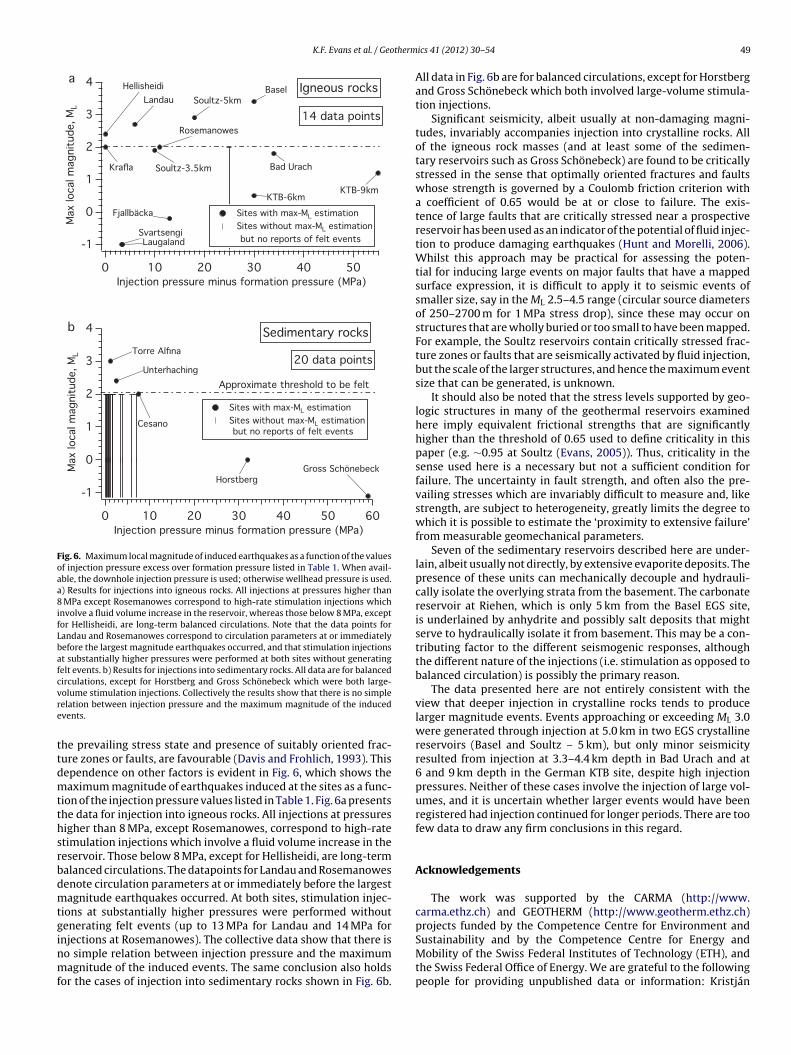
K.F. Evans et al. / Geotherm
4
3
2
1
0
-1
Max
loca
l mag
nitu
de, M
L
50403020100Injection pressure minus formation pressure (MPa)
Igneous rocksBaselSoultz-5kmLandau
14 data points
KTB-9km
Bad Urach
Sites with max-ML estimation Sites without max-ML estimation
but no reports of felt events
KTB-6km
Hellisheidi
LaugalandSvartsengi
Rosemanowes
Krafla
Fjallbäcka
Soultz-3.5km
4
3
2
1
0
-1
Max
loca
l mag
nitu
de, M
L
6050403020100Injection pressure minus formation pressure (MPa)
Sedimentary rocks
Approximate threshold to be feltUnterhaching
Sites with max-ML estimation Sites without max-ML estimation
but no reports of felt events
Torre Alfina
Cesano
20 data points
Gross SchönebeckHorstberg
a
b
Fig. 6. Maximum local magnitude of induced earthquakes as a function of the valuesof injection pressure excess over formation pressure listed in Table 1. When avail-able, the downhole injection pressure is used; otherwise wellhead pressure is used.a) Results for injections into igneous rocks. All injections at pressures higher than8 MPa except Rosemanowes correspond to high-rate stimulation injections whichinvolve a fluid volume increase in the reservoir, whereas those below 8 MPa, exceptfor Hellisheidi, are long-term balanced circulations. Note that the data points forLandau and Rosemanowes correspond to circulation parameters at or immediatelybefore the largest magnitude earthquakes occurred, and that stimulation injectionsat substantially higher pressures were performed at both sites without generatingfelt events. b) Results for injections into sedimentary rocks. All data are for balancedcirculations, except for Horstberg and Gross Schönebeck which were both large-vre
ttdmtthsrbdmtginmf
olume stimulation injections. Collectively the results show that there is no simpleelation between injection pressure and the maximum magnitude of the inducedvents.
he prevailing stress state and presence of suitably oriented frac-ure zones or faults, are favourable (Davis and Frohlich, 1993). Thisependence on other factors is evident in Fig. 6, which shows theaximum magnitude of earthquakes induced at the sites as a func-
ion of the injection pressure values listed in Table 1. Fig. 6a presentshe data for injection into igneous rocks. All injections at pressuresigher than 8 MPa, except Rosemanowes, correspond to high-ratetimulation injections which involve a fluid volume increase in theeservoir. Those below 8 MPa, except for Hellisheidi, are long-termalanced circulations. The datapoints for Landau and Rosemanowesenote circulation parameters at or immediately before the largestagnitude earthquakes occurred. At both sites, stimulation injec-
ions at substantially higher pressures were performed withoutenerating felt events (up to 13 MPa for Landau and 14 MPa for
njections at Rosemanowes). The collective data show that there iso simple relation between injection pressure and the maximumagnitude of the induced events. The same conclusion also holdsor the cases of injection into sedimentary rocks shown in Fig. 6b.
ics 41 (2012) 30– 54 49
All data in Fig. 6b are for balanced circulations, except for Horstbergand Gross Schönebeck which both involved large-volume stimula-tion injections.
Significant seismicity, albeit usually at non-damaging magni-tudes, invariably accompanies injection into crystalline rocks. Allof the igneous rock masses (and at least some of the sedimen-tary reservoirs such as Gross Schönebeck) are found to be criticallystressed in the sense that optimally oriented fractures and faultswhose strength is governed by a Coulomb friction criterion witha coefficient of 0.65 would be at or close to failure. The exis-tence of large faults that are critically stressed near a prospectivereservoir has been used as an indicator of the potential of fluid injec-tion to produce damaging earthquakes (Hunt and Morelli, 2006).Whilst this approach may be practical for assessing the poten-tial for inducing large events on major faults that have a mappedsurface expression, it is difficult to apply it to seismic events ofsmaller size, say in the ML 2.5–4.5 range (circular source diametersof 250–2700 m for 1 MPa stress drop), since these may occur onstructures that are wholly buried or too small to have been mapped.For example, the Soultz reservoirs contain critically stressed frac-ture zones or faults that are seismically activated by fluid injection,but the scale of the larger structures, and hence the maximum eventsize that can be generated, is unknown.
It should also be noted that the stress levels supported by geo-logic structures in many of the geothermal reservoirs examinedhere imply equivalent frictional strengths that are significantlyhigher than the threshold of 0.65 used to define criticality in thispaper (e.g. ∼0.95 at Soultz (Evans, 2005)). Thus, criticality in thesense used here is a necessary but not a sufficient condition forfailure. The uncertainty in fault strength, and often also the pre-vailing stresses which are invariably difficult to measure and, likestrength, are subject to heterogeneity, greatly limits the degree towhich it is possible to estimate the ‘proximity to extensive failure’from measurable geomechanical parameters.
Seven of the sedimentary reservoirs described here are under-lain, albeit usually not directly, by extensive evaporite deposits. Thepresence of these units can mechanically decouple and hydrauli-cally isolate the overlying strata from the basement. The carbonatereservoir at Riehen, which is only 5 km from the Basel EGS site,is underlained by anhydrite and possibly salt deposits that mightserve to hydraulically isolate it from basement. This may be a con-tributing factor to the different seismogenic responses, althoughthe different nature of the injections (i.e. stimulation as opposed tobalanced circulation) is possibly the primary reason.
The data presented here are not entirely consistent with theview that deeper injection in crystalline rocks tends to producelarger magnitude events. Events approaching or exceeding ML 3.0were generated through injection at 5.0 km in two EGS crystallinereservoirs (Basel and Soultz – 5 km), but only minor seismicityresulted from injection at 3.3–4.4 km depth in Bad Urach and at6 and 9 km depth in the German KTB site, despite high injectionpressures. Neither of these cases involve the injection of large vol-umes, and it is uncertain whether larger events would have beenregistered had injection continued for longer periods. There are toofew data to draw any firm conclusions in this regard.
Acknowledgements
The work was supported by the CARMA (http://www.carma.ethz.ch) and GEOTHERM (http://www.geotherm.ethz.ch)projects funded by the Competence Centre for Environment and
Sustainability and by the Competence Centre for Energy andMobility of the Swiss Federal Institutes of Technology (ETH), andthe Swiss Federal Office of Energy. We are grateful to the followingpeople for providing unpublished data or information: Kristján
5 therm
ÁABShETGUPMiKG(d(STIoGGDHhRnJaZfL
R
A
A
A
A
A
A
B
B
B
B
B
B
B
0 K.F. Evans et al. / Geo
gústsson (ISOR, Iceland), Gudni Axelsson (ISOR, Iceland), Juliangerer (Stadtwerke München GmbH, Munich, Germany), Stefanaisch (Q-Con, Bad Bergzabern, Germany), Franc ois Cornet (IPGS,trasbourg, France), Nicolas Cuenot (EEIG Heat Mining, Kutzen-ausen, France), Ola Eiken (Statoil, Trondheim, Norway), Lorenzichinger (Hydroisotop GmbH, Schweitenkirchen, Germany),homas Fritzer (Bayerisches Landesamt für Umwelt, Munich,ermany), Wolfgang Geisinger (Geothermie Unterhaching GmbH,nterhaching, Germany), Ásgrímur Gudmundsson (Landsvirkjunower, Reykjavik), Andy Jupe (Altcom Ltd., Penzance, UK),ichael Kaelcke (Innovative Energie für Pullach GmbH, Pullach
. Isartal, Germany), Beata Kêpinska (Polish Academy of Science,raków, Poland), Erwin Knapek (former Mayor of Unterhaching,ermany), Stefan Lüth (GFZ-Potsdam, Germany), Udo Reimer
Stadtwerke-Waren, Waren, Germany), Uwe Richlak (Neubran-enburger Stadtwerke, Neubrandenburg, Germany), Ulrich SchanzGeoenergy-Bayern GmbH, Regensdorf, Bavaria, Germany), Jochenchneider (Hydroisotop GmbH, Schweitenkirchen, Germany),ore Torp (Statoil, Trondheim, Norway), Pierre Ungemach (GPCnstrumentation Process, Paris), Kristín Vogfjörd (Icelandic Mete-rological Office, Reykjavík, Iceland), Thomas Wallroth (Bergab,othenburg, Sweden), Joachim Wassermann (Munich University,ermany) and Michael Weber (GFZ-Potsdam, Germany). We thankavid Bruhn (GFZ-Potsdam, Germany), Agust Gudmundsson (Royalolloway College, London), Reinhard Jung (Jung-Geotherm, Isern-agen, Germany), Grzegorz Kwiatek (GFZ-Potsdam, Germany),üdiger Schulz (Leibnitz Institute for Applied Geophysics, Han-over, Germany), Ingrid Stober (Freiburg University, Germany) and
oachem Poppei (AF-Colenco, Baden, Switzerland) for discussionnd assistance in locating information, and Bjørn Oddsson (ETH-ürich, Switzerland) for Icelandic translations. The comments ofour reviewers and the editors, Drs. Sabodh Garg and Marceloippmann, helped improve the manuscript.
eferences
gustsson, K., Halldorsson, P., 2005. Seismic hazard in the Hengill area based on theSIL earthquake catalogue (First results). Report no. 05015. Vedurstofa, Reykjavik,Iceland, 39 pp.
horner, L., Murawski, H., Schneider, G., 1970a. Die Verbreitung von schaden-vurursachenden Erdbeben auf dem Gebiet der Bundesrepublik Deutschland.Zeitschrift für Geophysik 36, 313–343.
horner, L., Murawski, H., Schneider, G., 1970b. The distribution of earthquakes caus-ing damage on the territory of the Federal Republic of Germany. Zeitschrift fürGeophysik 36, 313–343 (in German).
rnason, A., Eysteinsson, H., Hersir, G.P., 2010. Joint 1D inversion of TEM and MTdata and 3D inversion of MT data in the Hengill area, SW Iceland. Geothermics39, 13–34, doi:10.1016/j.geothermics.2010.01.002.
xelsson, G., Flovenz, O.G., Hjartarson, A., Hauksdottir, S., Sverrisdottir, G., Arnason,F., Arnason, A., Bodvarson, R., 2000. Thermal energy extraction by reinjectionfrom Laugaland geothermal system in North Iceland. In: Proceedings: WorldGeothermal Congress, Kyushu-Tohoku, Japan, May 28–June 10, pp. 3027–3032.
xelsson, G., Thórhallsson, S., Björnsson, G., 2006. Stimulation of geothermal wellsin basaltic rock in Iceland. In: Proceedings ENGINE Workshop 3: Stimulation ofReservoir and Microseismicity, Ittingen, Switzerland, 29 June–1 July, pp. 17–25.
aisch, S., Harjes, H.P., 2003. A model for fluid-injection-induced seismicity at theKTB, Germany. Geophysical Journal International 152, 160–170.
aisch, S., Weidler, R., Voeroes, R., Tenzer, H., Teza, D., 2004. Improving hydraulicstimulation efficiency by means of real-time monitoring. In: Proceedings 29thWorkshop on Geothermal Reservoir Engineering, Stanford University, Stanford,CA, USA, January 26–28, p. 7.
aklid, A., Korbøl, R., 1996. Sleipner Vest CO2 disposal, CO2 injection into a shallowunderground aquifer. In: Proceedings of SPE Annual Technical Conference andExhibition. SPE Paper Number 36600, Denver, Colorado, October 2–9, p. 9.
arelli, A., Ceccarelli, A., Dini, I., Fiordelisi, A., Giorgi, N., Lovari, F., Romagnoli, P.,2010. A review of the Mt. Amiata geothermal system (Italy). In: Proceedings ofWorld Geothermal Congress 2010, Bali, Indonesia, April 25-29, p. 6.
aria, R., Baumgaerner, J., Gérard, A., Jung, R., 1997. European hot dry rock geother-mal research programme 1996-1997. Final Report to the European Commission,Brussels, Belgium, 192 pp.
aria, R., Green, A.S.P., 1990. Microseismics: a key to understanding reservoirgrowth. In: Proceedings of Camborne School of Mines International Hot Dry RockConference, Camborne School of Mines, Redruth, U.K., June 27–30, pp. 363–377.
aria, R., Hearn, K., Batchelor, A.S., 1985. Induced seismicity during the hydraulicstimulation of a potential Hot Dry Rock geothermal reservoir. In: Proceedings
ics 41 (2012) 30– 54
of 4th Conf. on Acoustic Emision/Microseismic Activity in Geologic Structuresand Materials, Pennsylvania State University, State Park, Pennsylvania, USA, pp.327–352.
Baria, R., Michelet, S., Baumgärtner, J., Dyer, B.C., Gerard, A., Nicholls, J., Hettkamp,T., Teza, D., Soma, N., Asanuma, H., Garnish, J., Megel, T., 2004. Microseismicmonitoring of the world’s largest potential HDR reservoir. In: Proceedings 29thWorkshop on Geothermal Reservoir Engineering, Stanford University, Stanford,CA, USA, January 26-28, pp. 194–201.
Batchelor, A.S., Baria, R., Hearn, K., 1983. Monitoring the effects of hydraulic stimu-lation by microseismic event location: a case study. In: Presented at 58th Ann.Tech. Conf. and Exhibition of SPE, San Francisco, California, SPE Paper Number12109, p. 12.
Batini, F., Bufe, C., Cameli, G.M., Console, R., Fiordelisi, A., 1980a. Seismic moni-toring in Italian geothermal areas I: seismic activity in the Larderello-Travaleregion. In: Proceedings Second DOE-ENEL Workshop on Cooperative Research inGeothermal Energy, Report LBL-11555, Lawrence Berkeley Laboratory, Berkeley,CA, USA, October 20–22, pp. 20–47.
Batini, F., Cameli, G.M., Carabelli, E., Fiordelisi, A., 1980b. Seismic monitoring inItalian geothermal areas II: seismic activity in the geothermal fields duringexploitation. In: Proceedings of Second DOE-ENEL Workshop on CooperativeResearch in Geothermal Energy, Report LBL-11555, Lawrence Berkeley Labora-tory, Berkeley, CA, USA, October 20–22, pp. 48–85.
Batini, F., Console, R., Luongo, G., 1985. Seismological study of Larderello-Travalegeothermal area. Geothermics 14 (2–3), 255–272.
Batini, F., Fiordelisi, A., Moia, F., 1990. Main features of the seismicity in the MonteAmiata and Latera geothermal areas (Italy). In: Presented at XXII General Assem-bly European Seismological Commission, Barcelona, Spain, September 17–22,pp. 649–654.
Baumgärtner, J., Teza, D., Hettkamp, T., Gandy, T., Schindler, M., 2010a. Geothermalreservoir development in the Upper Rhine Graben – “Concepts, Techniques andExperiences”, the geothermal projects in Landau and Insheim. In: Presented atSecond European Geothermal Review, Bestec GmbH, Landau, Germany, Mainz,Germany, June 21–23, p. 31.
Baumgärtner, J., Teza, D., Hettkamp, T., Hauffe, P., 2010b. Stimulierung tiefer geother-mischer Systeme, (Stimulation of deep geothermal systems). BBR (Fachmagazinfür Brunnen- und Leitungsbau). Sonderheft Tiefe Geothermie 14–23, 84.
Baumgärtner, J., Teza, D., Hettkamp, T., Homeier, G., 2006. Geothermal explorationin the Upper Rhine valley in Germany. In: Proceedings of the ENGINE LaunchingConference, Orléans, France, February 12–15, p. 24.
Bayerische-Landtag, 2009. Schriftliche Antwort auf Anfrage des AbgeordnetenLudwig Wörner SPD vom 05.03.2009 über Geothermiebohrungen (Record ofproceedings of the 16th Electoral-Period (2008-2013)). Report no. 16/1233.Bayerische Landtag (Parliament of Bavarian States), Munich, Germany, 2 pp.Available at http://www.bayern.landtag.de/cps/rde.
Bertani, R., 2005. World geothermal power generation in the period 2001-2005.Geothermics 34, 651–690, doi:10.1016/j.geothermics.2005.09.005.
Bertini, G., Capetti, G., Fiordelisi, A., 2005. Characteristics of geothermal fields inItaly. Giornale di Geologia Applicata 1, 247–254, doi:10.1474/GGA.2005-01.0-24.0024.
BGS, 2011. British Geological Survey web report of 27th May 2011 event,(http://www.bgs.ac.uk/research/earthquakes/BlackpoolMay2011.html).
Billi, B., Capetti, G., Luccioli, F., 1986. ENEL activity in the research, exploration andexploitation of geothermal energy in Italy. Geothermics 15 (5–6), 765–779.
Bjornsson, G., 2004. Reservoir conditions at 3-6 km depth in the Hellisheidi Geother-mal Field, SW Iceland, estimated by deep drilling, coldwater injection, andseismic monitoring. In: Proceedings 29th Workshop on Geothermal ReservoirEngineering, Stanford University, Stanford, CA, USA, January 26–28, pp. 67–74.
Bohnhoff, M., Dresen, G., Ellsworth, W.L., Ito, H., 2010. Passive seismic monitoringof natural and induced earthquakes: case studies, future directions and socio-economic relevance. In: Cloetingh, S., Negendank, J. (Eds.), New Frontiers inIntegrated Solid Earth Sciences: International Year of Planet Earth. Springer,Dordrecht, Netherlands, pp. 261–285.
Bönnemann, C., Schmidt, B., Ritter, J., Gestermann, N., Plenefisch, T., Wegler,U., 2010. Das seismische Ereignis bei Landau vom 15 August 2009 (Theseismic event near Landau of 15th August 2010). Final report by the expertpanel on seismic risk associated with hydrothermal geothermal plants,Landesamt für Geologie und Bergbau of Rheinland-Pfalz (Regional authorityfor geology and mines of Rheinland-Pfalz), 54 pp. Available at http://www.lgb-rlp.de/einzelansicht.html?&no cache=1&tx ttnews%5BbackPid%5D=1542&txttnews%5Btt news%5D=64.
Brandsdóttir, B., Franzson, H., Einarsson, P., Árnason, K., Kristmannsdóttir, H., 2002.Seismic monitoring during an injection experiment in the Svartsengi geothermalfield, Iceland. Jökull 51, 43–52.
Brogi, F., Fabbrini, L., 2009. Extensional and strike-slip tectonics across the MonteAmiata–Monte Cetona transect (Northern Apennines, Italy) and seismotectonicimplications. Tectonophysics 476, 195–209, doi:10.1016/j.tecto.2009.02.020.
Brudy, M., Zoback, M.D., Fuchs, K., Rummel, F., Baümgartner, J., 1997. Estimation ofthe complete stress tensor to 8 km depth in the KTB scientific drill holes: implica-tions for crustal strength. Journal Geophysical Research 102 (B8), 18453–18475.
Bujakowski, W., 2000. The pilot project of a geothermal heat recuperation cascadesystem for fish and vegetable breeding, the Pas-Meeri Geothermal Laboratory
(Podhale region, Poland). In: Proceedings World Geothermal Congress, Kyushu-Tohoku, Japan, May 28–June 10, pp. 3379–3383.Cameli, G.M, Carabelli, E., Fiordelisi, A., Graziano, F., 1983. Survey of local seismicactivity during production and reinjection of geothermal fluids in Cesano andLatera areas. In: Proceedings of European Geothermal Update, 3rd International
therm
C
C
C
C
C
C
C
C
C
C
D
D
D
D
D
D
D
D
D
D
E
E
E
E
E
F
G
K.F. Evans et al. / Geo
Seminar on the Results of EC Geothermal Energy research, European Commu-nity, Munich, Germany, November 29–December 1, pp. 232–240.
ammerer, F., Hann, H.P., Martin, M., Obermaier, M., Pechnig, R., Reinold, M., Rupf,I., Schellschmidt, R., Simon, T., Stober, I., Wolpert, P., Zedler, H., 2009. Mach-barkeitstudie für ein Hot Dry Rock Wärme- und Stromnutzungskonzept BadUrach. BMU Report No. FKZ: 0327615A. Stadt Bad Urach, Germany, 118 pp.
appetti, G., Romagnoli, P., Sabatelli, F., 2010. Geothermal power generation in Italy:2005-2009 update report. In: Proceedings of World Geothermal Congress 2010,Bali, Indonesia, April 25–29, p. 8.
arabelli, E., Moia, F., Fiordelisi, A., 1984. Seismic monitoring during geothermalwells stimulation as contribution to the individuation of prevailing fracturationtrends. In: Presented at Seminar on Utilization of Geothermal Energy for ElectricPower Production and Space Heating, Florence, Italy, May 14–17, pp. 1–31.
harléty, J., Cuenot, N., Dorbath, L., Dorbath, C., Haessler, H., Frogneux, M., 2007. Largeearthquakes during hydraulic stimulations at the geothermal site of Soultz-sous-Forêts. International Journal Rock Mechanics Mining Sciences 44, 1091–1105.
ipolla, C.L., 2009. Modelling production and evaluating fracture performance inunconventional gas reservoirs. Journal Petroleum Technology 61 (9), 84–90.
ornet, F.H., 1989. Experimental investigations of forced fluid flow through a graniterock mass. In: Proceedings of 4th Int. Seminar on the Results of EC GeothermalEnergy Demonstration, Florence, Italy, April 27–30, pp. 189–204.
ornet, F.H., Bérard, F.H., Bourouis, S., 2007. How close to failure is a granite rockmass at a 5 km depth? International Journal Rock Mechanics Mining Sciences44, 47–66.
ornet, F.H., Burlet, D., 1992. Stress field determination in France by hydraulic testsin boreholes. Journal Geophysical Research 97 (B8), 11829–11849.
SM-Report, 1989. Camborne Geothermal Energy Project 2C-5 Final Report Phase2C. Report ETSU G 137F, Camborne School of Mines, Penryn, Cornwall, U.K., 42pp.
uenot, N., Dorbath, C., Frogneux, M., Langet, N., 2010. Microseismic activity inducedunder circulation conditions at the EGS Project of Soultz-sous-Forêts (France).In: Proceedings World Geothermal Conference, Bali, Indonesia, 25–29 April, p.9.
adlez, R., 2003. Mesozoic thickness pattern in the Mid-Polish Trough. GeologicalQuarterly 47 (3), 223–240.
adlez, R., Narkiewicz, M., Stephenson, R.A., Visser, M.T.M., van Wees, J.-D., 1995.Tectonic evolution of the Mid-Polish Trough: modelling implications and signif-icance for central European geology. Tectonophysics 252, 179–195.
avis, S.D., Frohlich, C., 1993. Did (or will) fluid injection cause earthquakes? –criteria for rational assessment. Seismological Research Letters 64, 207–224.
eichmann, N., Ernst, J., 2009. Earthquake focal mechanism solutions of the inducedseismicity in 2006 and 2007 below Basel (Switzerland). Swiss Journal Geo-sciences 102, 457–466, doi:10.1007/s00015-009-1336-y.
eichmann, N., Giardini, D., 2009. Earthquakes induced by the stimulation ofan Enhanced Geothermal System below Basel (Switzerland). SeismologicalResearch Letters 80 (5), 784–798, doi:10.1789/gssrl.80.5.784.
ietrich, H.G., 1982. Geological results from the Urach-3 borehole and the corre-lation with other boreholes. In: Hänel, R. (Ed.), The Urach Geothermal Project.Schweizerbart’sche Verlagsbuchhandlung, Stuttgart, Germany, pp. 49–58.
lugosz, P., Nagy, S., 1995. Determination of hydrodynamic parameters of the Pod-hale geothermal reservoir. Bulletin Polish Academy Sciences-Earth Science 43(4), 225–242.
oebl, F., 1968. Die geothermischen Verhältnisse des Ölfeldes Landau/Pfalz. In: Pro-ceedings of Graben Problems: International Rift Symposium, October10–12, E.Schweizerbart’sche Verlagsbuchhandlung, Karlsruhe, Germany, pp. 192–207.
ong E&P, 2004. Geothermal well MAH-2, 5512/11-2 (Margretheholm-2). ReportNo. 17060. Geological Survey of Denmark and Greenland, Copenhagen,Denmark, 18 pp.
orbath, L., Cuenot, N., Genter, A., Frogneux, M., 2009. Seismic response of thefractured and faulted granite of Soultz-sous-Forêts (France) to 5 km deepmassive water injections. Geophysics Journal International 117, 653–675,doi:10.1111/j.1365-246X.2009.04030.x.
iken, O., Ringrose, P., Hermanrud, C., Nazarian, B., Torp, T.A., Høier, L., 2011. Lessonslearned from 14 years of CCS operations: Sleipner. In Salah and Snøhvit. EnergyProcedia 4, 5541–5548, doi:10.1016/j.egypro.2011.02.541.
liasson, T., Sundquist, U., Wallroth, T., 1988. Stimulation experiments with waterand viscous fluid at the HDR research site in the Bohus granite, SW Sweden.Report no. Fj-6. Chalmers University of Technology, Gothenburg, Sweden, 69pp.
liasson, T., Sundquist, U., Wallroth, T., 1990. Circulation experiments in 1989 atFyällbacka HDR test site. Report no. Fj-10. Chalmers University of Technology,Gothenburg, Sweden, 56 pp.
vans, K.F., 2005. Permeability creation and damage due to massive fluid injectionsinto granite at 3.5 km at Soultz: part 2 – critical stress and fracture strength.Journal Geophysical Research 110, 14, doi:10.1029/2004JB003169.
vans, K.F., Kohl, T., Hopkirk, R.J., Rybach, L., 1992. Modelling of energyproduction from Hot Dry Rock systems. Report. Swiss Federal Instituteof Technology/Polydynamics, Zürich, Switzerland, 316 pp. Available athttp://www.geothermal.ethz.ch/publications.htm.
oulger, G.R., Long, R.E., Einarsson, P., Bjornsson, A., 1989. Implosive earthquakesat the active accretionary plate boundary in northern Iceland. Nature 337,
640–642.enter, A., Evans, K.F., Cuenot, N., Fritsch, D., Sanjuan, B., 2010. The Soultz geothermaladventure: 20 years of research and exploration of deep crystalline frac-tured rocks for EGS development. Comptes Rendus Geoscience 342, 502–516,doi:10.1016/j.crte.2010.01.006.
ics 41 (2012) 30– 54 51
Giardini, D., Grünthal, G., Shedlock, K., Zhang, P., 1999. The GSHAP Global seismichazard map. Annali di Geofisica 42 (6), 1225–1230.
Gibowicz, S.J., 1990. Seismicity induced by mining. Advances in Geophysics 32, 1–74.Goldbrunner, J.E., 1999. Hydrogeology of deep groundwater in Austria. Mitteilungen
der Österreichischen Geologischen Gesellschaft 92, 281–294.Goldbrunner, J.E., 2005a. Bad Blumau (Styria, Austria). The success story of com-
bined use of geothermal energy. Geo-Heat Centre (GHC) Quarterly Bulletin 26(2), 27–30.
Goldbrunner, J.E., 2005b. State, possible future developments and barriers of theexploration and exploitation of geothermal energy in Austria – Country update.In: Proceedings World Geothermal Congress, Antalya, Turkey, April 24–29, p.11.
Goldbrunner, J.E., 2005c. Zur Situation der Tiefen Geothermie in Österreich (Stateof deep geothermal resource utilisation in Austria). Geothermische Energie 48,22–25.
Goldbrunner, J.E., 2007. Thermalwassererschließungen - wissenschaftlicheBegleitung von Bohrungen einschließlich Bohrlochuntersuchungen (Researchon thermal water exploitation). BBR (Fachmagazin für Brunnen- undLeitungsbau) 11, 26–33.
Goldbrunner, J.E., 2010. Austria – country update. In: Proceedings of World Geother-mal Congress, Bali, Indonesia, April 25–29, p. 14.
Goldbrunner, J.E., Shirbaz, A., Heiss, H.P., 2007. Wasserwirtschaftliche Bewertungder Thermalwassernutzungen in Oberösterreich: Berichtszeitraum 2000–2005(Economic evaluation of thermal water usage in Austria). Report Amt derOberösterreich. Landesregierung, Wasserwirtschaft, Grund- und Trinkwasser-wirtschaft, Wasserwirtschaft Land Oberösterreich, L., Linz, Austria, 36 pp.
Grüntal, G., Musson, R.M.W., Schwarz, J., Stucchi, M., 1998. European MacroseismicScale 1998 (EMS-98). Cahiers du Centre Européen de Géodynamique et de Séis-mologie 15. Centre Européen de Géodynamique et de Séismologie, Luxembourg,99 pp.
Grünthal, G., Wahlström, R., Stromeyer, D., 2009. The unified catalogue of earth-quakes in central, northern, and northwestern Europe (CENEC) – updatedand expanded to the last millenium. Journal of Seismology 13 (4), 517–541,doi:10.1007/s10950-008-9144-9.
Gudmundsson, A., 2001. An expansion of the Krafla Power Plant from 30 to 60 MWe:geothermal considerations. Transactions Geothermal Resources Council 25,741–746.
Gupta, H.K., 1992. Reservoir-Induced Earthquakes. Elsevier, Amsterdam, TheNetherlands, 364 pp.
Guterch, B., Lewandowska-Marciniak, H., Niewiadomski, J., 2005. Earthquakesrecorded in Poland along the Pieniny Klippen Belt, Western Carpathians. ActaGeophysica Polonica 53 (1), 27–45.
Haering, M.O., Schanz, U., Ladner, F., Dyer, B.C., 2008. Characterisation of the basel-1enhanced geothermal system. Geothermics 37, 469–495.
Hansen, H., Eiken, O., Aasum, T.O., 2005. Tracing the path of carbon dioxide from agas/condensate reservoir, through an Amine plant and back into the subsurfaceaquifer – case study: the Sleipner area, Norwegian North Sea. In: Offshore Europe2005, SPE Paper Number 96742, Aberdeen, Scotland, UK 6–7 September, p. 15.
Hauber, L., 1991. Ergebnisse der Geothermmiebohrungen Riehen 1 und 2 sowieReinach 1 im Südosten des Rheingrabens (Results of the geothermal bore-holes Riehen 1, 2 and Reinach in the southeastern Rhein Graben). GeologischesJahrbuch E48, 167–184.
Heederick, J.P., 1997. Improvement of the injectivity index of argillaceous sandstone.Report no. NITG 97-260-A. Netherlands Institute of Applied Geoscience, Delft,The Netherlands, 183 pp.
Heidbach, O., Tingay, M., Barth, A., Reinecker, J., Kurfess, D., Müller, B., 2010. Globalcrustal stress pattern based on the World Stress Map database release 2008.Tectonophysics 428 (1–2), 3–15.
Heinemann, B., Troschke, B., Tenzer, H., 1992. Hydraulic investigations and stressevaluation at the HDR test site Urach 3, Germany. Transactions GeothermalResources Council 16, 425–431.
Helm, J.A., 1996. The natural seismic hazard and induced seismicity of the EuropeanHDR (Hot Dry Rock) geothermal energy project at Soultz-sous-Forêts, France.Doctoral thesis. Université Louis-Pasteur de Strasbourg, Strasbourg, France, 197pp.
Herzberger, P., Münch, W., Köbel, T., Bruchmann, U., Schlagermann, P.H.H., Wolf, L.,Rettenmaier, D., Steger, H., Zorn, R., Seibt, P., Möllmann, G.U., Sauter, M., Ghergut,J., Ptak, T., 2010. The geothermal power plant Bruchsal. In: Proceedings WorldGeothermal Congress 2010, Bali, Indonesia, April 25–29, p. 6.
Hettkamp, T., Teza, D., Baumgärtner, J., Gandy, T., Homeier, G., 2007. A multi-horizonapproach for the exploration and exploitation of a fractured geothermal reser-voir in Landau/Palatine. In: Presented at First European Geothermal Review,Mainz, Germany, October 29–31, p. 15.
Huenges, E., Trautwein, U., Legarth, B., Zimmermann, G., 2006. Fluid pressurevariation in a sedimentary geothermal reservoir in the North-German basin:case study gross Schönebeck. Pure and Applied Geophysics 163, 2141–2152,doi:10.1007/s00024-006-0122-2.
Hunt, S.P., Morelli, C.P., 2006. Cooper basin HDR seismic hazard evaluation: predic-tive modelling of local stress changes due to HFR geothermal energy operationsin South Australia. Report 2006/16. University of Adelaide, Adelaide, Australia,50 pp.
Husen, S., Bachmann, C., Giardini, D., 2007. Locally triggered seismicity in the centralSwiss Alps following the large rainfall event of August 2005. Geophysical JournalInternational 171, 1126–1134, doi:10.1111/j.1365-246X.2007.03561.x.
Illies, J.H., Greiner, G., 1978. Rhinegraben and the Alpine system. Geological SocietyAmerica Bulletin 89, 770–782.
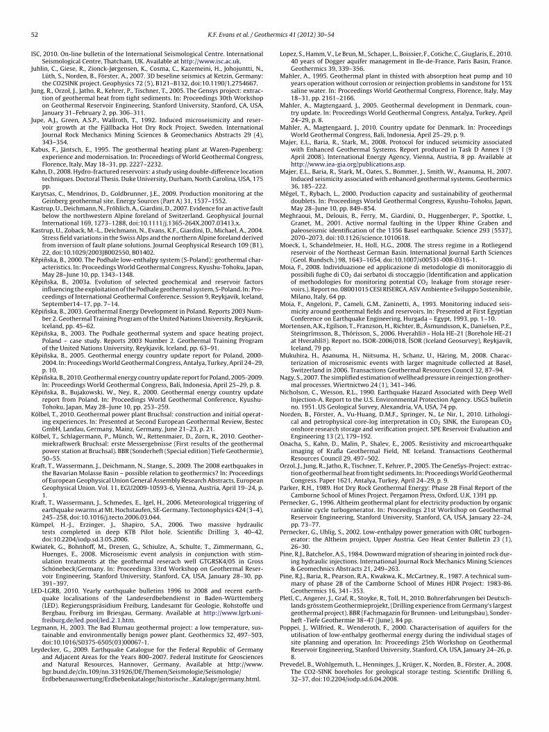
5 therm
I
J
J
J
K
K
K
K
K
K
K
K
K
K
K
K
K
K
K
K
K
K
L
L
L
2 K.F. Evans et al. / Geo
SC, 2010. On-line bulletin of the International Seismological Centre. InternationalSeismological Centre, Thatcham, UK. Available at http://www.isc.ac.uk.
uhlin, C., Giese, R., Zionck-Jørgensen, K., Cosma, C., Kazemeini, H., Johojuntti, N.,Lüth, S., Norden, B., Förster, A., 2007. 3D beseline seismics at Ketzin, Germany:the CO2SINK project. Geophysics 72 (5), B121–B132, doi:10.1190/1.2754667.
ung, R., Orzol, J., Jatho, R., Kehrer, P., Tischner, T., 2005. The Gensys project: extrac-tion of geothermal heat from tight sediments. In: Proceedings 30th Workshopon Geothermal Reservoir Engineering, Stanford University, Stanford, CA, USA,January 31–February 2, pp. 306–311.
upe, A.J., Green, A.S.P., Wallroth, T., 1992. Induced microseismicity and reser-voir growth at the Fjällbacka Hot Dry Rock Project, Sweden. InternationalJournal Rock Mechanics Mining Sciences & Geomechanics Abstracts 29 (4),343–354.
abus, F., Jäntsch, E., 1995. The geothermal heating plant at Waren-Papenberg:experience and modernisation. In: Proceedings of World Geothermal Congress,Florence, Italy, May 18–31, pp. 2227–2232.
ahn, D., 2008. Hydro-fractured reservoirs: a study using double-difference locationtechniques. Doctoral Thesis. Duke University, Durham, North Carolina, USA, 175pp.
arytsas, C., Mendrinos, D., Goldbrunner, J.E., 2009. Production monitoring at theGeinberg geothermal site. Energy Sources (Part A) 31, 1537–1552.
astrup, U., Deichmann, N., Fröhlich, A., Giardini, D., 2007. Evidence for an active faultbelow the northwestern Alpine foreland of Switzerland. Geophysical JournalInternational 169, 1273–1288, doi:10.1111/j.1365-264X.2007.03413.x.
astrup, U., Zoback, M.-L., Deichmann, N., Evans, K.F., Giardini, D., Michael, A., 2004.Stress field variations in the Swiss Alps and the northern Alpine foreland derivedfrom inversion of fault plane solutions. Journal Geophysical Research 109 (B1),22, doi:10.1029/2003JB002550, B01402.
êpinska, B., 2000. The Podhale low-enthalpy system (S-Poland): geothermal char-acteristics. In: Proceedings World Geothermal Congress, Kyushu-Tohoku, Japan,May 28–June 10, pp. 1343–1348.
êpinska, B., 2003a. Evolution of selected geochemical and reservoir factorsinfluencing the exploitation of the Podhale geothermal system, S-Poland. In: Pro-ceedings of International Geothermal Conference. Session 9, Reykjavik, Iceland,September14–17, pp. 7–14.
êpinska, B., 2003. Geothermal Energy Development in Poland. Reports 2003 Num-ber 2. Geothermal Training Program of the United Nations University, Reykjavik,Iceland, pp. 45–62.
êpinska, B., 2003. The Podhale geothermal system and space heating project,Poland – case study. Reports 2003 Number 2. Geothermal Training Programof the United Nations University, Reykjavik, Iceland, pp. 63–91.
êpinska, B., 2005. Geothermal energy country update report for Poland, 2000-2004. In: Proceedings World Geothermal Congress, Antalya, Turkey, April 24–29,p. 10.
êpinska, B., 2010. Geothermal energy country update report for Poland, 2005-2009.In: Proceedings World Geothermal Congress, Bali, Indonesia, April 25–29, p. 8.
êpinska, B., Bujakowski, W., Ney, R., 2000. Geothermal energy country updatereport from Poland. In: Proceedings World Geothermal Conference, Kyushu-Tohoku, Japan, May 28–June 10, pp. 253–259.
ölbel, T., 2010. Geothermal power plant Bruchsal: construction and initial operat-ing experiences. In: Presented at Second European Geothermal Review, BestecGmbH, Landau, Germany, Mainz, Germany, June 21–23, p. 21.
ölbel, T., Schlagermann, P., Münch, W., Rettenmaier, D., Zorn, R., 2010. Geother-miekraftwerk Bruchsal: erste Messergebnisse (First results of the geothermalpower station at Bruchsal). BBR (Sonderheft (Special edition) Tiefe Geothermie),50–55.
raft, T., Wassermann, J., Deichmann, N., Stange, S., 2009. The 2008 earthquakes inthe Bavarian Molasse Basin – possible relation to geothermics? In: Proceedingsof European Geophysical Union General Assembly Research Abstracts, EuropeanGeophysical Union. Vol. 11, EGU2009-10593-6, Vienna, Austria, April 19–24, p.1.
raft, T., Wassermann, J., Schmedes, E., Igel, H., 2006. Meteorological triggering ofearthquake swarms at Mt. Hochstaufen, SE-Germany. Tectonophysics 424 (3–4),245–258, doi:10.1016/j.tecto.2006.03.044.
ümpel, H.-J., Erzinger, J., Shapiro, S.A., 2006. Two massive hydraulictests completed in deep KTB Pilot hole. Scientific Drilling 3, 40–42,doi:10.2204/iodp.sd.3.05.2006.
wiatek, G., Bohnhoff, M., Dresen, G., Schiulze, A., Schulte, T., Zimmermann, G.,Huenges, E., 2008. Microseismic event analysis in conjunction with stim-ulation treatments at the geothermal reserach well GTGRSK4/05 in GrossSchönebeck/Germany. In: Proceedings 33rd Workshop on Geothermal Reser-voir Engineering, Stanford University, Stanford, CA, USA, January 28–30, pp.391–397.
ED-LGRB, 2010. Yearly earthquake bulletins 1996 to 2008 and recent earth-quake localisations of the Landeserdbebendienst in Baden-Württemberg(LED). Regierungspräsidium Freiburg, Landesamt für Geologie, Rohstoffe undBergbau, Freiburg im Briesgau, Germany. Available at http://www.lgrb.uni-freiburg.de/led pool/led 2 1.htm.
egmann, H., 2003. The Bad Blumau geothermal project: a low temperature, sus-tainable and environmentally benign power plant. Geothermics 32, 497–503,doi:10.1016/S0375-6505(03)00067-1.
eydecker, G., 2009. Earthquake Catalogue for the Federal Republic of Germanyand Adjacent Areas for the Years 800–2007. Federal Institute for Geosciencesand Natural Resources, Hannover, Germany, Available at http://www.bgr.bund.de/cln 109/nn 331926/DE/Themen/Seismologie/Seismologie/Erdbebenauswertung/Erdbebenkataloge/historische Kataloge/germany.html.
ics 41 (2012) 30– 54
Lopez, S., Hamm, V., Le Brun, M., Schaper, L., Boissier, F., Cotiche, C., Giuglaris, E., 2010.40 years of Dogger aquifer management in Ile-de-France, Paris Basin, France.Geothermics 39, 339–356.
Mahler, A., 1995. Geothermal plant in thisted with absorption heat pump and 10years operation without corrosion or reinjection problems in sandstone for 15%saline water. In: Proceedings World Geothermal Congress, Florence, Italy, May18–31, pp. 2161–2166.
Mahler, A., Magtengaard, J., 2005. Geothermal development in Denmark, coun-try update. In: Proceedings World Geothermal Congress, Antalya, Turkey, April24–29, p. 8.
Mahler, A., Magtengaard, J., 2010. Country update for Denmark. In: ProceedingsWorld Geothermal Congress, Bali, Indonesia, April 25–29, p. 9.
Majer, E.L., Baria, R., Stark, M., 2008. Protocol for induced seismicity associatedwith Enhanced Geothermal Systems. Report produced in Task D Annex I (9April 2008). International Energy Agency, Vienna, Austria, 8 pp. Available athttp://www.iea-gia.org/publications.asp.
Majer, E.L., Baria, R., Stark, M., Oates, S., Bommer, J., Smith, W., Asanuma, H., 2007.Induced seismicity associated with enhanced geothermal systems. Geothermics36, 185–222.
Mégel, T., Rybach, L., 2000. Production capacity and sustainability of geothermaldoublets. In: Proceedings World Geothermal Congress, Kyushu-Tohoku, Japan,May 28–June 10, pp. 849–854.
Meghraoui, M., Delouis, B., Ferry, M., Giardini, D., Huggenberger, P., Spottke, I.,Granet, M., 2001. Active normal faulting in the Upper Rhine Graben andpaleoseismic identification of the 1356 Basel earthquake. Science 293 (5537),2070–2073, doi:10.1126/science.1010618.
Moeck, I., Schandelmeier, H., Holl, H.G., 2008. The stress regime in a Rotliegendreservoir of the Northeast German Basin. International Journal Earth Sciences(Geol. Rundsch.) 98, 1643–1654, doi:10.1007/s00531-008-0316-1.
Moia, F., 2008. Individuazione ed applicazione di metodologie di monitoraggio dipossibili fughe di CO2 dai serbatoi di stoccaggio (Identification and applicationof methodologies for monitoring potential CO2 leakage from storage reser-voirs.). Report no. 08001015 CESI RISERCA. ASV Ambiente e Sviluppo Sostenibile,Milano, Italy, 64 pp.
Moia, F., Angeloni, P., Cameli, G.M., Zaninetti, A., 1993. Monitoring induced seis-micity around geothermal fields and reservoirs. In: Presented at First EgyptianConference on Earthquake Engineering, Hurgada – Egypt, 1993, pp. 1–10.
Mortensen, A.K., Egilson, T., Franzson, H., Richter, B., Ásmundsson, K., Danielsen, P.E.,Steingrímsson, B., Thórisson, S., 2006. Hverahlíð - Hola HE-21 (Borehole HE-21at Hverahlíð). Report no. ISOR-2006/018, ÍSOR (Iceland Geosurvey), Reykjavik,Iceland, 79 pp.
Mukuhira, H., Asanuma, H., Niitsuma, H., Schanz, U., Häring, M., 2008. Charac-terization of microseismic events with larger magnitude collected at Basel,Switzerland in 2006. Transactions Geothermal Resources Council 32, 87–94.
Nagy, S., 2007. The simplified estimation of wellhead pressure in reinjection geother-mal processes. Wiertnictwo 24 (1), 341–346.
Nicholson, C., Wesson, R.L., 1990. Earthquake Hazard Associated with Deep WellInjection-A. Report to the U.S. Environmental Protection Agency. USGS bulletinno. 1951. US Geological Survey, Alexandria, VA, USA, 74 pp.
Norden, B., Förster, A., Vu-Huang, D.M.F., Springer, N., Le Nir, I., 2010. Lithologi-cal and petrophysical core-log interpretation in CO2 SINK, the European CO2
onshore research storage and verification project. SPE Reservoir Evaluation andEngineering 13 (2), 179–192.
Onacha, S., Kahn, D., Malin, P., Shalev, E., 2005. Resistivity and microearthquakeimaging of Krafla Geothermal Field, NE Iceland. Transactions GeothermalResources Council 29, 497–502.
Orzol, J., Jung, R., Jatho, R., Tischner, T., Kehrer, P., 2005. The GeneSys-Project: extrac-tion of geothermal heat from tight sediments. In: Proceedings World GeothermalCongress. Paper 1621, Antalya, Turkey, April 24–29, p. 9.
Parker, R.H., 1989. Hot Dry Rock Geothermal Energy: Phase 2B Final Report of theCamborne School of Mines Project. Pergamon Press, Oxford, U.K, 1391 pp.
Pernecker, G., 1996. Altheim geothermal plant for electricity production by organicrankine cycle turbogenerator. In: Proceedings 21st Workshop on GeothermalReservoir Engineering, Stanford University, Stanford, CA, USA, January 22–24,pp. 73–77.
Pernecker, G., Uhlig, S., 2002. Low-enthalpy power generation with ORC turbogen-erator: the Altheim project, Upper Austria. Geo Heat Center Bulletin 23 (1),26–30.
Pine, R.J., Batchelor, A.S., 1984. Downward migration of shearing in jointed rock dur-ing hydraulic injections. International Journal Rock Mechanics Mining Sciences& Geomechnics Abstracts 21, 249–263.
Pine, R.J., Baria, R., Pearson, R.A., Kwakwa, K., McCartney, R., 1987. A technical sum-mary of phase 2B of the Camborne School of Mines HDR Project: 1983-86.Geothermics 16, 341–353.
Pletl, C., Angerer, J., Graf, R., Stoyke, R., Toll, H., 2010. Bohrerfahrungen bei Deutsch-lands grösstem Geothermieprojekt, (Drilling experience from Germany’s largestgeothermal project). BBR (Fachmagazin für Brunnen- und Leitungsbau), Sonder-heft -Tiefe Geothermie 38–47 (June), 84 pp.
Poppei, J., Wilfried, R., Wenderoth, F., 2000. Characterisation of aquifers for theutilisation of low-enthalpy geothermal energy during the individual stages ofsite planning and operation. In: Proceedings 25th Workshop on Geothermal
Reservoir Engineering, Stanford University, Stanford, CA, USA, January 24–26, p.8.Prevedel, B., Wohlgemuth, L., Henninges, J., Krüger, K., Norden, B., Förster, A., 2008.The CO2-SINK boreholes for geological storage testing. Scientific Drilling 6,32–37, doi:10.2204/iodp.sd.6.04.2008.
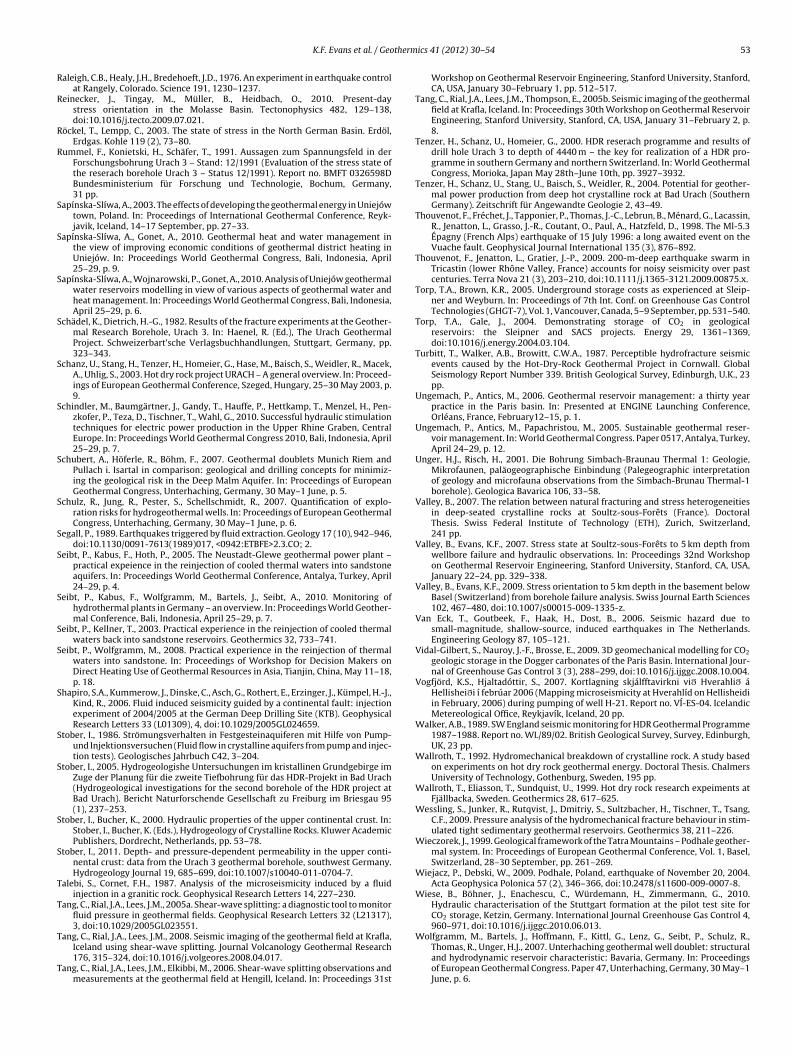
therm
R
R
R
R
S
S
S
S
S
S
S
S
S
S
S
S
S
S
S
S
S
S
T
T
T
T
K.F. Evans et al. / Geo
aleigh, C.B., Healy, J.H., Bredehoeft, J.D., 1976. An experiment in earthquake controlat Rangely, Colorado. Science 191, 1230–1237.
einecker, J., Tingay, M., Müller, B., Heidbach, O., 2010. Present-daystress orientation in the Molasse Basin. Tectonophysics 482, 129–138,doi:10.1016/j.tecto.2009.07.021.
öckel, T., Lempp, C., 2003. The state of stress in the North German Basin. Erdöl,Erdgas. Kohle 119 (2), 73–80.
ummel, F., Konietski, H., Schäfer, T., 1991. Aussagen zum Spannungsfeld in derForschungsbohrung Urach 3 – Stand: 12/1991 (Evaluation of the stress state ofthe reserach borehole Urach 3 – Status 12/1991). Report no. BMFT 0326598DBundesministerium für Forschung und Technologie, Bochum, Germany,31 pp.
apínska-Slíwa, A., 2003. The effects of developing the geothermal energy in Uniejówtown, Poland. In: Proceedings of International Geothermal Conference, Reyk-javik, Iceland, 14–17 September, pp. 27–33.
apínska-Slíwa, A., Gonet, A., 2010. Geothermal heat and water management inthe view of improving economic conditions of geothermal district heating inUniejów. In: Proceedings World Geothermal Congress, Bali, Indonesia, April25–29, p. 9.
apínska-Slíwa, A., Wojnarowski, P., Gonet, A., 2010. Analysis of Uniejów geothermalwater reservoirs modelling in view of various aspects of geothermal water andheat management. In: Proceedings World Geothermal Congress, Bali, Indonesia,April 25–29, p. 6.
chädel, K., Dietrich, H.-G., 1982. Results of the fracture experiments at the Geother-mal Research Borehole, Urach 3. In: Haenel, R. (Ed.), The Urach GeothermalProject. Schweizerbart’sche Verlagsbuchhandlungen, Stuttgart, Germany, pp.323–343.
chanz, U., Stang, H., Tenzer, H., Homeier, G., Hase, M., Baisch, S., Weidler, R., Macek,A., Uhlig, S., 2003. Hot dry rock project URACH – A general overview. In: Proceed-ings of European Geothermal Conference, Szeged, Hungary, 25–30 May 2003, p.9.
chindler, M., Baumgärtner, J., Gandy, T., Hauffe, P., Hettkamp, T., Menzel, H., Pen-zkofer, P., Teza, D., Tischner, T., Wahl, G., 2010. Successful hydraulic stimulationtechniques for electric power production in the Upper Rhine Graben, CentralEurope. In: Proceedings World Geothermal Congress 2010, Bali, Indonesia, April25–29, p. 7.
chubert, A., Höferle, R., Böhm, F., 2007. Geothermal doublets Munich Riem andPullach i. Isartal in comparison: geological and drilling concepts for minimiz-ing the geological risk in the Deep Malm Aquifer. In: Proceedings of EuropeanGeothermal Congress, Unterhaching, Germany, 30 May–1 June, p. 5.
chulz, R., Jung, R., Pester, S., Schellschmidt, R., 2007. Quantification of explo-ration risks for hydrogeothermal wells. In: Proceedings of European GeothermalCongress, Unterhaching, Germany, 30 May–1 June, p. 6.
egall, P., 1989. Earthquakes triggered by fluid extraction. Geology 17 (10), 942–946,doi:10.1130/0091-7613(1989)017, <0942:ETBFE>2.3.CO; 2.
eibt, P., Kabus, F., Hoth, P., 2005. The Neustadt-Glewe geothermal power plant –practical expeience in the reinjection of cooled thermal waters into sandstoneaquifers. In: Proceedings World Geothermal Conference, Antalya, Turkey, April24–29, p. 4.
eibt, P., Kabus, F., Wolfgramm, M., Bartels, J., Seibt, A., 2010. Monitoring ofhydrothermal plants in Germany – an overview. In: Proceedings World Geother-mal Conference, Bali, Indonesia, April 25–29, p. 7.
eibt, P., Kellner, T., 2003. Practical experience in the reinjection of cooled thermalwaters back into sandstone reservoirs. Geothermics 32, 733–741.
eibt, P., Wolfgramm, M., 2008. Practical experience in the reinjection of thermalwaters into sandstone. In: Proceedings of Workshop for Decision Makers onDirect Heating Use of Geothermal Resources in Asia, Tianjin, China, May 11–18,p. 18.
hapiro, S.A., Kummerow, J., Dinske, C., Asch, G., Rothert, E., Erzinger, J., Kümpel, H.-J.,Kind, R., 2006. Fluid induced seismicity guided by a continental fault: injectionexperiment of 2004/2005 at the German Deep Drilling Site (KTB). GeophysicalResearch Letters 33 (L01309), 4, doi:10.1029/2005GL024659.
tober, I., 1986. Strömungsverhalten in Festgesteinaquiferen mit Hilfe von Pump-und Injektionsversuchen (Fluid flow in crystalline aquifers from pump and injec-tion tests). Geologisches Jahrbuch C42, 3–204.
tober, I., 2005. Hydrogeologishe Untersuchungen im kristallinen Grundgebirge imZuge der Planung für die zweite Tiefbohrung für das HDR-Projekt in Bad Urach(Hydrogeological investigations for the second borehole of the HDR project atBad Urach). Bericht Naturforschende Gesellschaft zu Freiburg im Briesgau 95(1), 237–253.
tober, I., Bucher, K., 2000. Hydraulic properties of the upper continental crust. In:Stober, I., Bucher, K. (Eds.), Hydrogeology of Crystalline Rocks. Kluwer AcademicPublishers, Dordrecht, Netherlands, pp. 53–78.
tober, I., 2011. Depth- and pressure-dependent permeability in the upper conti-nental crust: data from the Urach 3 geothermal borehole, southwest Germany.Hydrogeology Journal 19, 685–699, doi:10.1007/s10040-011-0704-7.
alebi, S., Cornet, F.H., 1987. Analysis of the microseismicity induced by a fluidinjection in a granitic rock. Geophysical Research Letters 14, 227–230.
ang, C., Rial, J.A., Lees, J.M., 2005a. Shear-wave splitting: a diagnostic tool to monitorfluid pressure in geothermal fields. Geophysical Research Letters 32 (L21317),3, doi:10.1029/2005GL023551.
ang, C., Rial, J.A., Lees, J.M., 2008. Seismic imaging of the geothermal field at Krafla,Iceland using shear-wave splitting. Journal Volcanology Geothermal Research176, 315–324, doi:10.1016/j.volgeores.2008.04.017.
ang, C., Rial, J.A., Lees, J.M., Elkibbi, M., 2006. Shear-wave splitting observations andmeasurements at the geothermal field at Hengill, Iceland. In: Proceedings 31st
ics 41 (2012) 30– 54 53
Workshop on Geothermal Reservoir Engineering, Stanford University, Stanford,CA, USA, January 30–February 1, pp. 512–517.
Tang, C., Rial, J.A., Lees, J.M., Thompson, E., 2005b. Seismic imaging of the geothermalfield at Krafla, Iceland. In: Proceedings 30th Workshop on Geothermal ReservoirEngineering, Stanford University, Stanford, CA, USA, January 31–February 2, p.8.
Tenzer, H., Schanz, U., Homeier, G., 2000. HDR reserach programme and results ofdrill hole Urach 3 to depth of 4440 m – the key for realization of a HDR pro-gramme in southern Germany and northern Switzerland. In: World GeothermalCongress, Morioka, Japan May 28th–June 10th, pp. 3927–3932.
Tenzer, H., Schanz, U., Stang, U., Baisch, S., Weidler, R., 2004. Potential for geother-mal power production from deep hot crystalline rock at Bad Urach (SouthernGermany). Zeitschrift für Angewandte Geologie 2, 43–49.
Thouvenot, F., Fréchet, J., Tapponier, P., Thomas, J.-C., Lebrun, B., Ménard, G., Lacassin,R., Jenatton, L., Grasso, J.-R., Coutant, O., Paul, A., Hatzfeld, D., 1998. The Ml-5.3Épagny (French Alps) earthquake of 15 July 1996: a long awaited event on theVuache fault. Geophysical Journal International 135 (3), 876–892.
Thouvenot, F., Jenatton, L., Gratier, J.-P., 2009. 200-m-deep earthquake swarm inTricastin (lower Rhône Valley, France) accounts for noisy seismicity over pastcenturies. Terra Nova 21 (3), 203–210, doi:10.1111/j.1365-3121.2009.00875.x.
Torp, T.A., Brown, K.R., 2005. Underground storage costs as experienced at Sleip-ner and Weyburn. In: Proceedings of 7th Int. Conf. on Greenhouse Gas ControlTechnologies (GHGT-7), Vol. 1, Vancouver, Canada, 5–9 September, pp. 531–540.
Torp, T.A., Gale, J., 2004. Demonstrating storage of CO2 in geologicalreservoirs: the Sleipner and SACS projects. Energy 29, 1361–1369,doi:10.1016/j.energy.2004.03.104.
Turbitt, T., Walker, A.B., Browitt, C.W.A., 1987. Perceptible hydrofracture seismicevents caused by the Hot-Dry-Rock Geothermal Project in Cornwall. GlobalSeismology Report Number 339. British Geological Survey, Edinburgh, U.K., 23pp.
Ungemach, P., Antics, M., 2006. Geothermal reservoir management: a thirty yearpractice in the Paris basin. In: Presented at ENGINE Launching Conference,Orléans, France, February12–15, p. 1.
Ungemach, P., Antics, M., Papachristou, M., 2005. Sustainable geothermal reser-voir management. In: World Geothermal Congress. Paper 0517, Antalya, Turkey,April 24–29, p. 12.
Unger, H.J., Risch, H., 2001. Die Bohrung Simbach-Braunau Thermal 1: Geologie,Mikrofaunen, paläogeographische Einbindung (Palegeographic interpretationof geology and microfauna observations from the Simbach-Brunau Thermal-1borehole). Geologica Bavarica 106, 33–58.
Valley, B., 2007. The relation between natural fracturing and stress heterogeneitiesin deep-seated crystalline rocks at Soultz-sous-Forêts (France). DoctoralThesis. Swiss Federal Institute of Technology (ETH), Zurich, Switzerland,241 pp.
Valley, B., Evans, K.F., 2007. Stress state at Soultz-sous-Forêts to 5 km depth fromwellbore failure and hydraulic observations. In: Proceedings 32nd Workshopon Geothermal Reservoir Engineering, Stanford University, Stanford, CA, USA,January 22–24, pp. 329–338.
Valley, B., Evans, K.F., 2009. Stress orientation to 5 km depth in the basement belowBasel (Switzerland) from borehole failure analysis. Swiss Journal Earth Sciences102, 467–480, doi:10.1007/s00015-009-1335-z.
Van Eck, T., Goutbeek, F., Haak, H., Dost, B., 2006. Seismic hazard due tosmall-magnitude, shallow-source, induced earthquakes in The Netherlands.Engineering Geology 87, 105–121.
Vidal-Gilbert, S., Nauroy, J.-F., Brosse, E., 2009. 3D geomechanical modelling for CO2
geologic storage in the Dogger carbonates of the Paris Basin. International Jour-nal of Greenhouse Gas Control 3 (3), 288–299, doi:10.1016/j.ijggc.2008.10.004.
Vogfjörd, K.S., Hjaltadóttir, S., 2007. Kortlagning skjálfftavirkni við Hverahlið áHellisheiði í febrúar 2006 (Mapping microseismicity at Hverahlíd on Hellisheidiin February, 2006) during pumping of well H-21. Report no. VÍ-ES-04. IcelandicMetereological Office, Reykjavík, Iceland, 20 pp.
Walker, A.B., 1989. SW England seismic monitoring for HDR Geothermal Programme1987–1988. Report no. WL/89/02. British Geological Survey, Survey, Edinburgh,UK, 23 pp.
Wallroth, T., 1992. Hydromechanical breakdown of crystalline rock. A study basedon experiments on hot dry rock geothermal energy. Doctoral Thesis. ChalmersUniversity of Technology, Gothenburg, Sweden, 195 pp.
Wallroth, T., Eliasson, T., Sundquist, U., 1999. Hot dry rock research expeiments atFjällbacka, Sweden. Geothermics 28, 617–625.
Wessling, S., Junker, R., Rutqvist, J., Dmitriy, S., Sultzbacher, H., Tischner, T., Tsang,C.F., 2009. Pressure analysis of the hydromechanical fracture behaviour in stim-ulated tight sedimentary geothermal reservoirs. Geothermics 38, 211–226.
Wieczorek, J., 1999. Geological framework of the Tatra Mountains – Podhale geother-mal system. In: Proceedings of European Geothermal Conference, Vol. 1, Basel,Switzerland, 28–30 September, pp. 261–269.
Wiejacz, P., Debski, W., 2009. Podhale, Poland, earthquake of November 20, 2004.Acta Geophysica Polonica 57 (2), 346–366, doi:10.2478/s11600-009-0007-8.
Wiese, B., Böhner, J., Enachescu, C., Würdemann, H., Zimmermann, G., 2010.Hydraulic characterisation of the Stuttgart formation at the pilot test site forCO2 storage, Ketzin, Germany. International Journal Greenhouse Gas Control 4,960–971, doi:10.1016/j.ijggc.2010.06.013.
Wolfgramm, M., Bartels, J., Hoffmann, F., Kittl, G., Lenz, G., Seibt, P., Schulz, R.,Thomas, R., Unger, H.J., 2007. Unterhaching geothermal well doublet: structuraland hydrodynamic reservoir characteristic: Bavaria, Germany. In: Proceedingsof European Geothermal Congress. Paper 47, Unterhaching, Germany, 30 May–1June, p. 6.

5 therm
W
Z
4 K.F. Evans et al. / Geo
ürdemann, H., Möller, F., Kühn, M., Heidug, W., Christensen, N.-P., Borm,G., Schilling, F.R., 2010. CO2SINK – from site characterisation andrisk assessment to monitoring and verification: one year of opera-tional experience with the field laboratory for CO2 storage at Ketzin,Germany. International Journal Greenhouse Gas Control 4, 938–951,doi:10.1016/j.ijggc.2010.08.010.
immermann, G., Reinicke, A., Brandt, W., Blöcker, G., Milsch, H., Holl, H.-G., Moeck,I., Schulte, T., Saadat, A., Huenges, E., 2008. Results of stimulation treatmentsat the geothermal reserach wells in Gross Schönebeck. In: Proceedings 33rdWorkshop on Geothermal Reservoir Engineering, Stanford University, Stanford,CA, USA, January 28–30, pp. 96–100.
ics 41 (2012) 30– 54
Zinivicius, F., Rasteniene, V., Bickus, A., 2003. Geothermal development in Lithuania.In: Proceedings of European Geothermal Conference, Szeged, Hungary, 25–30May, p. 9.
Zinivicius, F., Sliupa, S., 2010. Lithuania – geothermal energy country update. In:Proceedings World Geothermal Congress Bali, Indonesia, 25–29 April, p. 8.
Zoback, M.D., Harjes, H.P., 1997. Injection-induced earthquakes and crustal stress at
9 km depth at the KTB deep drilling site, Germany. Journal Geophysical Research102 (B8), 18477–18491.Zumberge, M., Nooner, S., Eiken, O., 2006. A seafloor survey of the Sleipner Fieldto monitor CO2 injection. Final report on contract DE-FC26-02NT41587. ScrippsIntitute of Oceanography, San Diego, California, 15 pp.