Embed Size (px)
Citation preview
FX-500SERIES
FX-SERIES HIGH END MODEL
DIGITAL FIBER SENSOR
Conforming to EMC Directive
At the industry’s leading edge
07/2010
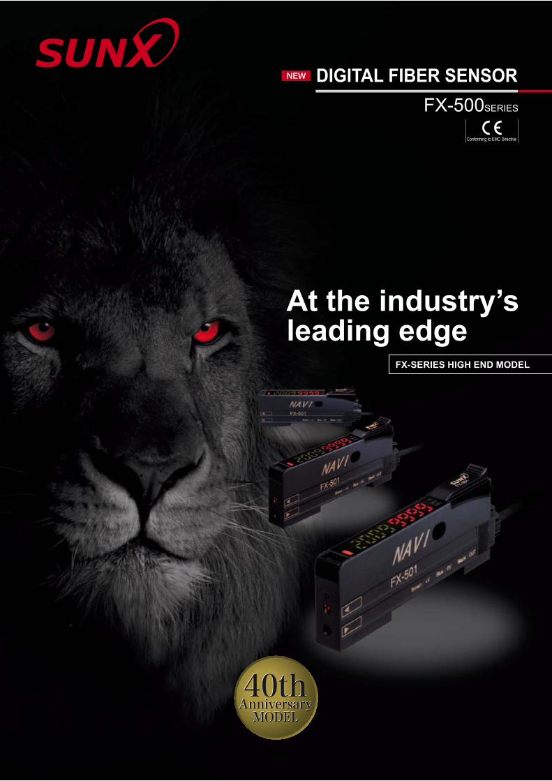
“Why are the values different even for the same detection?” “If we try to forcibly unify all the display values of incident light intensity, we will not be able to read the actual changes.”SUNX focuses on the variation among fiber sensors and aims for absolute digitalization.When the FX-500 series is used together with our super quality fiber, the incident light intensity variation among units is decreased to only 1/4 of that of conventional models.By being close to absolute values instead of modified digital values, changes in detection that could not be found in the past can now be monitored.
High stability!
In each unit we have accurately aligned the central axis of the fiber with the central axis of the emitted light, which creates a high coupling efficiency that helps to reduce variation among units.
Improved fiber coupling efficiency and suppressed variation among units
* Illustration is an image.
CO
NC
EPT
Requires setting different threshold values for each sensor.
Can control by using just one threshold value.
Super quality fiber
In the case where multiple fiber sensors are installed under the same operating conditions, the incident light intensities are nearly identical to each other, allowing for the specification of one threshold across all sensors.
Specifying just one value in an operation manual is possible
Because the incident light intensity is stable, the same threshold value can be used even when an amplifier is replaced. Also, copying of settings is easy when used together with optical communication.
Maintenance is easy on stabilized fiber sensors
When setting up fiber sensors in a row in the same layout, all incident light intensities will display nearly identical values once beams are aligned. This helps to raise installation precision and prevent trouble from occurring before equipment is turned on.
Stability in incident light intensity and confidence in beam adjustment
Previous amplifier
Fiber central axis
Beam central axis
Fiber core
Fiber insertion guide
Active coupling emission device
All sensors are aligned individually.
Large variation in incident light intensity. Incident light intensities
are stable.
FX-500 series
[from previous]
1/4incident light
intensity variation
+Threshold value Incident light intensity
Digital control is essentially achieved
Decrease the variation among fiber sensors
1
2
3
4
1 2 3 4
Stability of the incident light intensity is improved by 4 times*. Values of incident light intensity stay close together even after replacing an amplifier.
* Using a small diameter fiber (fiber core ø0.5 mm ø0.020 in). If using a standard fiber (fiber core ø1.0 mm ø0.039 in), the variation will be double of that of conventional models.
Threshold value Incident light intensity
1
2
3
4
Inci
dent
ligh
t int
ensi
ty
1 2 3 4
01 FX-500SERIES
Industry leading stability
07/2010
“Super quality fiber” with stable emission amount
“Stabilized incident light intensities” even in multiple unitsC
ON
CEPT
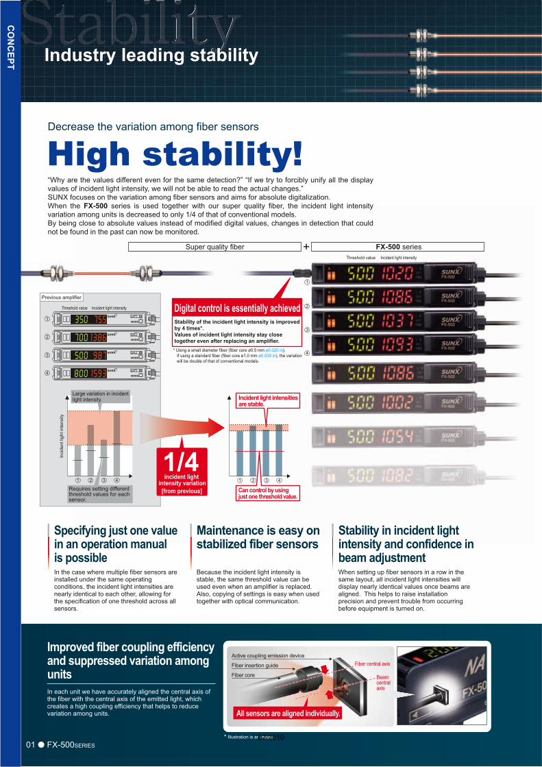
±10Variation in emission intensity is down to less than ±10 %Under our new manufacturing method and quality control system, we have developed fiber heads that have a stabilized light emission. When used with the FX-500 amplifier, a complete digital control is essentially achieved.
* For custom-ordered fibers of your required length, contact the sales office near you.
The beam axis deviation of each unit is kept within ±2 ° and the beam axis centering precision is kept within ±150 μm ±5.906 mil.
Introducing super quality fiber
The basic performance of a standard fiber is greatly enhanced!New fibers developed using a new manufacturing method adopted by our own factory along with a persistent quality control system
More bendable!
The basic performance of a standard fiber is greatly enhanced!g yTh b s r ormanancceee ooff aa sstatannnddararddd fibbbeer ir iss gggrereaeatltlyy eeennhahananccceded!d!TThThh bbb si frforma e ff a stt ndda ddd fibbbe ir is gre tltly enhha c ded!d!New fibers developed using a new manufacturing method adopted by our own factory along withw b r d v o e u i n w m n f t r g m h d a o e b u o n a o y g w ha persistent quality control systemaa pperse sisttenent qquaualityy cocontntrolol sysystes emmm
More bendable!
The basic performaTThThehe bbabasssicc ppeerfrfooormrmama
ø2.2 mm ø0.087 in0.087 in standard fiberStable emission intensity
A quality that surpassed standard fiber
More flexible!
Integrated high-precision plug
Expanded temperature range
The centering precision of the fiber core attached to the inserting plug is doubled. As the insertion precision is increased, the variation among units can be greatly suppressed.
Variation in emission intensity of the fiber core is controlled down to less than ±10 %, achieving a stable detection.
R4mmR0.157in
R4
Single core standard fiber with high flexibility
In general, high-flexibility types adopt a multi-fiber core which may result in large variation in light emission.
–55 to+80 °C–67 to+176 °F
Ambient temperature [– 40 to +70 °C – 40 to +158 °F in previous] Bending radius [Previous is R25 mm R0.984 in]
Bending durability [Previous is 1,000 times]
±10
1/6of that of previous
Super quality fiber reduces optical transmission loss to less than ±10 %y fiber reduces optical transmission loss to less than ±10 %yy b d c s p c t n m s o l s o e s 0 %
High precision polishing is accomplished by using the PCTM polishing technique. The specularity of the end face of the fiber is 5 times greater.
A high precision integrated plug is achieved with the centering precision of the fiber core being ±40 μm 1.575 mil.
more thanprevious
New
mat
eria
l
Pre
viou
s
1.2 times
10 milliontimes
10,000 timesmore than previous
02FX-500SERIES
1Point 2Point 3Point
Approx. 2 timesmore thanprevious
07/2010
Previous
FX-500HYPR mode
Max.
Satisfying both high speed and long range
FX-301 (LONG mode)
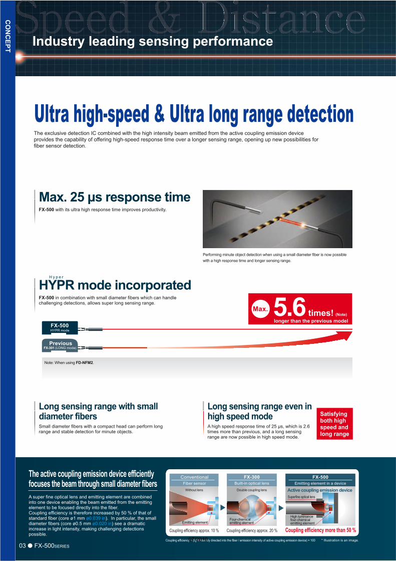
Performing minute object detection when using a small diameter fiber is now possible with a high response time and longer sensing range.
Note: When using FD-NFM2.
FX-500 with its ultra high response time improves productivity.
The exclusive detection IC combined with the high intensity beam emitted from the active coupling emission device provides the capability of offering high-speed response time over a longer sensing range, opening up new possibilities for fiber sensor detection.
Max. 25 μs response time
FX-500 in combination with small diameter fibers which can handle challenging detections, allows super long sensing range.
HYPR mode incorporatedH y p e r
5.6 times! (Note)longer than the previous model
Small diameter fibers with a compact head can perform long range and stable detection for minute objects.
Long sensing range with small diameter fibers
A high speed response time of 25 μs, which is 2.6 times more than previous, and a long sensing range are now possible in high speed mode.
Long sensing range even in high speed mode
The active coupling emission device efficiently focuses the beam through small diameter fibers
CO
NC
EPT
A super fine optical lens and emitting element are combined into one device enabling the beam emitted from the emitting element to be focused directly into the fiber.Coupling efficiency is therefore increased by 50 % of that of standard fiber (core ø1 mm ø0.039 in). In particular, the small diameter fibers (core ø0.5 mm ø0.020 in) see a dramatic increase in light intensity, making challenging detections possible.
03 FX-500SERIES
Industry leading sensing performance
Ultra high-speed & Ultra long range detection
Coupling efficiency = (light intensity directed into the fiber / emission intensity of active coupling emission device) × 100 * Illustration is an image.
ConventionalFiber sensor
Without lens
Emitting element
Coupling efficiency approx. 10 %
FX-300Built-in optical lens
Double coupling lens
Four-chemical emitting element
Coupling efficiency approx. 20 %
FX-500Emitting element in a device
Active coupling emission deviceSuperfine optical lens
Coupling efficiency more than 50 %
High luminance four-chemical emitting element
07/2010
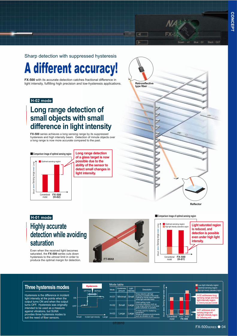
FX-500 with its accurate detection catches fractional difference in light intensity, fulfilling high precision and low-hysteresis applications.
FX-500 series achieves a long sensing range by its suppressed hysteresis and high intensity beam. Detection of minute objects over a long range is now more accurate compared to the past.
Long range detection of small objects with small difference in light intensity
FT-WA8
Reflector
H-01 mode
H-02 mode
Sho
rtLo
ng
Conventionalmodel
FX-500(H-02)
Comparison image of optimal sensing region
FX-500(H-01)
Light saturated region is reduced, and detection is possible even under high light intensity.
Optimal sensing region
High light intensity (saturation) region
A different accuracy!Sharp detection with suppressed hysteresis
Sens
ing re
nge
Conventionalmodel
Sho
rtLo
ngSe
nsing
reng
e
Comparison image of optimal sensing region
Optimal sensing region
Even when the received light becomes saturated, the FX-500 series cuts down hysteresis to the utmost limit in order to produce the optimal margin for detection.
Highly accurate detection while avoiding saturation
Long range detection of a glass target is now possible due to the ability of the sensor to detect small changes in light intensity.
Retroreflective Retroreflective type fibertype fiberRetroreflective type fiber
CO
NC
EPT
ON
Small Large
OFF Point ON Point
Incident light intensity
Mode table
Mode Hysteresisamount
Lightintensity
SmallMinimal
LargeSmall
LargeLarge
Description
H-01
H-02
H-03H-01
FX-500H-02
OFF
Hysteresis Low light intensity regionOptimal sensing regionHigh light intensity (saturation) region
Sho
rtLo
ngSe
nsing
reng
e
Conventionalmodel
Hysteresis is the difference in incident light intensity at the points when the output turns ON and when the output turns OFF. Hysteresis was originally intended to be used as a measure against vibrations, but SUNX provides three hysteresis modes to suit the need of fiber sensors.
Sharp detection with high accuracy is possible in this mode. Optimal for minute object detection where light saturates easily.
Initial setting mode. Accurate detection such as long range detection of a large glass substrate is possible.
A mode used for chattering prevention. Works in adverse environments such as vibration or dirt.
Three hysteresis modes
H-01 addresses short sensing range and high light intensity region.Ex. Detecting wire
H-02 addresses long sensing range and low light intensity region.Ex. Detecting large glass substrate
04FX-500SERIES07/2010
Previous space
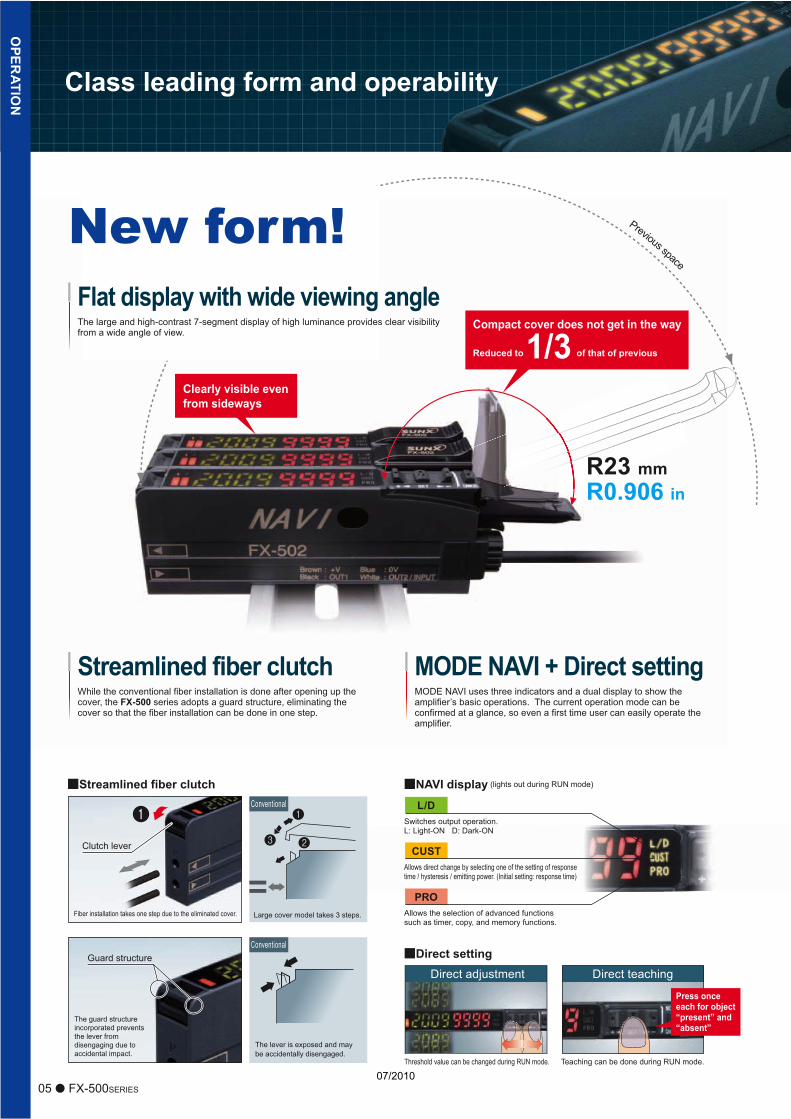
New form!The large and high-contrast 7-segment display of high luminance provides clear visibility from a wide angle of view.
Flat display with wide viewing angle
MODE NAVI uses three indicators and a dual display to show the amplifier’s basic operations. The current operation mode can be confirmed at a glance, so even a first time user can easily operate the amplifier.
MODE NAVI + Direct settingWhile the conventional fiber installation is done after opening up the cover, the FX-500 series adopts a guard structure, eliminating the cover so that the fiber installation can be done in one step.
Streamlined fiber clutch
Streamlined fiber clutch NAVI display (lights out during RUN mode)
Fiber installation takes one step due to the eliminated cover.
Clutch lever
Large cover model takes 3 steps.
Guard structure
Conventional
Conventional
Direct adjustment
L/D
Threshold value can be changed during RUN mode.
Direct teaching
Teaching can be done during RUN mode.
PROAllows the selection of advanced functions such as timer, copy, and memory functions.
CUSTAllows direct change by selecting one of the setting of response time / hysteresis / emitting power. (Initial setting: response time)
Switches output operation.L: Light-ON D: Dark-ON
OPER
ATION
The lever is exposed and may be accidentally disengaged.
The guard structure incorporated prevents the lever from disengaging due to accidental impact.
Press once each for object “present” and “absent”
Compact cover does not get in the way
Reduced to 1/3 of that of previous
Class leading form and operability
05 FX-500SERIES
Direct setting
Clearly visible even from sideways
R23 mmR0.906 in
07/2010
Time
Four-chemical emitting element + APC(FX-500)
Three-chemical emitting element(without APC)
Time
Stable sensing comparisonLi
ght e
miti
ng a
mou
nt
Long-term stability
Short-term stability
Deviation
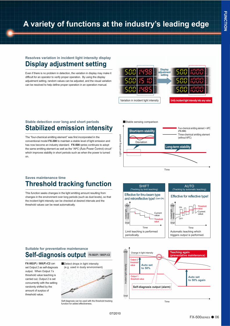
FX-502(P) / 505(P)-C2 can set Output 2 as self-diagnosis output. When Output 1’s threshold value teaching is carried out, Output 2 is set concurrently with the setting randomly shifted by the amount of surplus of threshold value.
This function seeks changes in the light emitting amount resulting from changes in the environment over long periods (such as dust levels), so that the incident light intensity can be checked at desired intervals and the threshold values can be reset automatically.
Time
Threshold value
Threshold value
SHIFT(Tracking by limit teaching)
Time
Incide
nt lig
ht int
ensit
y
Large
Small
CurrentvalueCurrent
value
Limit teaching is performed periodically.
Automatic teaching which triggers output is performed.
AUTO(Tracking by automatic teaching)
ON
OFF
Effective for thru-beam type and retroreflective type! (Dark-ON)
Effective for reflective type!
Output 2thresholdvalue
Output 1threshold value
Auto set to 50%
Auto set to 50% again
Change in light intensity
Self-diagnasis output (alarm)
Self-diagnosis can be used with the threshold tracking function for added effectiveness.
Displayadjustment
setting
Unify incident light intensity into any valueVariation in incident light intensity
06FX-500SERIES
Stable detection over long and short periods
Stabilized emission intensity
Saves maintenance time
Threshold tracking function
Resolves variation in incident light intensity display
Display adjustment setting
The “four-chemical emitting element” was first incorporated in the conventional model FX-300 to maintain a stable level of light emission and has now become an industry standard. FX-500 series continues to adopt the same emitting element as well as the “APC (Auto Power Control) circuit” which improves stability in short periods such as when the power is turned on.
Even if there is no problem in detection, the variation in display may make it difficult for an operator to verify proper operation. By using the display adjustment setting, random values can be adjusted, and the visual variation can be resolved to help define proper operation in an operation manual.
Incide
nt lig
ht int
ensit
y
Large
Small
Large
Small
Incid
ent l
ight
inte
nsityDetect drops in light intensity
(e.g. used in dusty environment)
Suitable for preventative maintenance
Self-diagnosis output Teaching again(preventative maintenance)FX-502(P) / 505(P)-C2
FUN
CTIO
NA variety of functions at the industry’s leading edge
07/2010
The number of data banks used for saving the setup conditions of the amplifier is increased to eight. Setup conditions can be saved and loaded to make setup changes easy at worksite that manufactures multiple models.
External input
Remote control improves work efficiencyWork efficiency can be improved by operating via a PLC output or other external signal.
Full-auto / Limit / 2-point teaching
Data bank load / save
Emission halt
Display adjustment setting
Logical calculation (self-unit only)
Copying function lock (self-unit only)
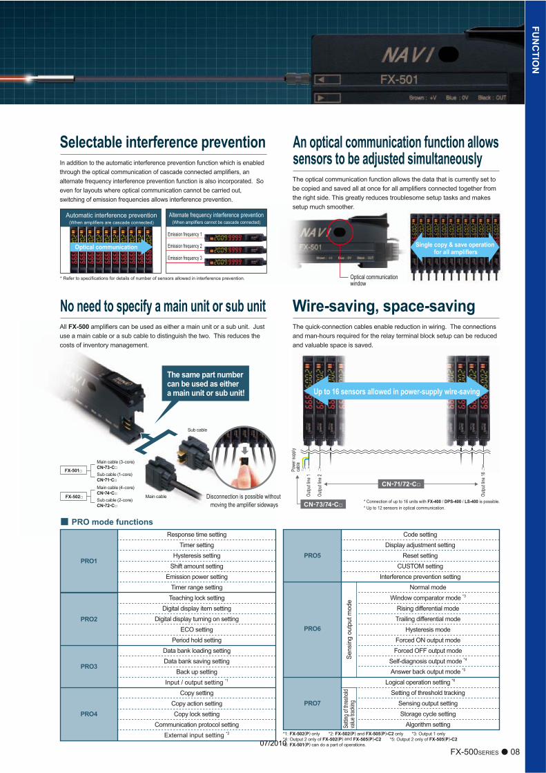
Time chart For L-ON
Sensingcondition
Beam-receivedBeam-interruptedONOFF
ONOFF
ONOFF
ONOFF
ONOFF
T2
T2
T1 T1
T1
T1
T1
T1T1
ON-delay
OFF-delay
ONE-SHOT
ON-delay •OFF-delay
ON-delay •ONE-SHOT
A wide variety of timer control operations can be carried out by these fiber sensors alone.
Timer period: 0.05 ms to 32 sOutput 1 has ON-delay • OFF-delay and ON-delay • ONE-SHOT timers.
Three logical calculations (AND, OR, XOR), are selectable using Output 1 of multiple FX-500 series amplifiers. A PLC is not required which helps to reduce material and programming and costs.
Logical calculation functions
Calculation result output
Detection fiber
Synchronization fiber
Calculation of two outputs in one amplifier
Calculation of two neighboring amplifiers
External input (sensor, contact, PLC, etc.)
Calculation result output
Normal output operation
Normal operation
Calculation of one amplifier and external input
Calculation result outputLower side Output 1
Upper side Output 1
Output 1
Output 1
Output 2
FX-502(P) / 505(P)-C2
FX-505(P)-C2
FX-502(P) / 505(P)-C2
FX-502(P) / 505(P)-C2
07 FX-500SERIES
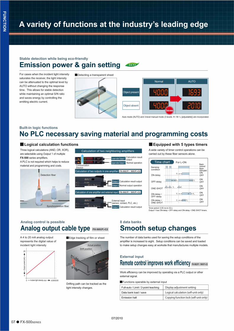
Auto mode (AUTO) and 3-level manual mode (3 levels: H / M / L [adjustable]) are incorporated.
Object present
Object absent
Normal AUTO
SaturatedSaturatedSaturated
Detecting a transparent sheet
Stable detection while being eco-friendly
Emission power & gain settingFor cases when the incident light intensity saturates the receiver, the light intensity can be attenuated to the optimal level by AUTO without changing the response time. This allows for stable detection while maintaining an optimal S/N ratio and saves energy by controlling the emitting electric current.
Built-in logic functions
No PLC necessary saving material and programming costs
Communicationdirection
Equipped with 5 types timers
Drifting path can be tracked as the light intensity changes.
Actual position
Drift position20
Outpu
t curr
ent (m
A)
4
4,000/8,0000 Incident light intensity (digit)Functions operable by external input
Edge tracking of film or sheetA 4 to 20 mA analog output represents the digital value of incident light intensity
Analog control is possible
Analog output cable type8 data banks
Smooth setup changesFU
NC
TION A variety of functions at the industry’s leading edge
07/2010
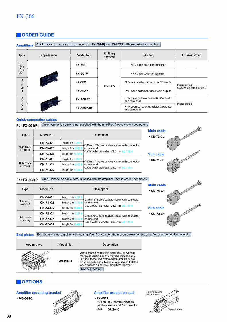
Selectable interference prevention
Single copy & save operation for all amplifiers
Optical communication window
Emission frequency 1
Emission frequency 2
Emission frequency 3
Up to 16 sensors allowed in power-supply wire-saving
* Connection of up to 16 units with FX-400 / DPS-400 / LS-400 is possible.* Up to 12 sensors in optical communication.CN-73/74-C□
Powe
r sup
plyca
ble
CN-71/72-C□
PRO mode functions
*1: FX-502(P) only *2: FX-502(P) and FX-505(P)-C2 only *3: Output 1 only*4: Output 2 only of FX-502(P) and FX-505(P)-C2 *5: Output 2 only of FX-505(P)-C2*6: FX-501(P) can do a part of operations.
PRO1
PRO2
PRO4
PRO5
PRO7
PRO6
PRO3
Response time setting Code settingDisplay adjustment setting
Reset settingCUSTOM setting
Interference prevention settingNormal mode
Window comparator mode *3
Rising differential modeTrailing differential mode
Hysteresis modeForced ON output modeForced OFF output mode
Self-diagnosis output mode *4
Answer back output mode *5
Logical operation setting *6
Setting of threshold trackingSensing output settingStorage cycle setting
Algorithm setting
Timer settingHysteresis setting
Shift amount settingEmission power setting
Timer range settingTeaching lock setting
Digital display item settingDigital display turning on setting
ECO settingPeriod hold setting
Data bank loading settingData bank saving setting
Back up settingInput / output setting *1
Copy settingCopy action settingCopy lock setting
Communication protocol settingExternal input setting *2
Sens
ing
outp
ut m
ode
Settin
g of th
resho
ldva
lue tra
cking
The quick-connection cables enable reduction in wiring. The connections and man-hours required for the relay terminal block setup can be reduced and valuable space is saved.
Wire-saving, space-savingAll FX-500 amplifiers can be used as either a main unit or a sub unit. Just use a main cable or a sub cable to distinguish the two. This reduces the costs of inventory management.
No need to specify a main unit or sub unit
Main cable
Sub cable
FX-502□
Main cable (4-core)CN-74-C□Sub cable (2-core)CN-72-C□
FX-501□
Main cable (3-core)CN-73-C□Sub cable (1-core)CN-71-C□
The same part number can be used as either a main unit or sub unit!
Disconnection is possible without moving the amplifier sideways
Optical communication
* Refer to specifications for details of number of sensors allowed in interference prevention.
Automatic interference prevention(When amplifiers are cascade connected)
Alternate frequency interference prevention(When amplifiers cannot be cascade connected)
An optical communication function allows sensors to be adjusted simultaneously
08FX-500SERIES
In addition to the automatic interference prevention function which is enabled through the optical communication of cascade connected amplifiers, an alternate frequency interference prevention function is also incorporated. So even for layouts where optical communication cannot be carried out, switching of emission frequencies allows interference prevention.
The optical communication function allows the data that is currently set to be copied and saved all at once for all amplifiers connected together from the right side. This greatly reduces troublesome setup tasks and makes setup much smoother.
Outpu
t line
1
Outpu
t line
2
Outpu
t line
16
FUN
CTIO
N
07/2010
FX-500
09
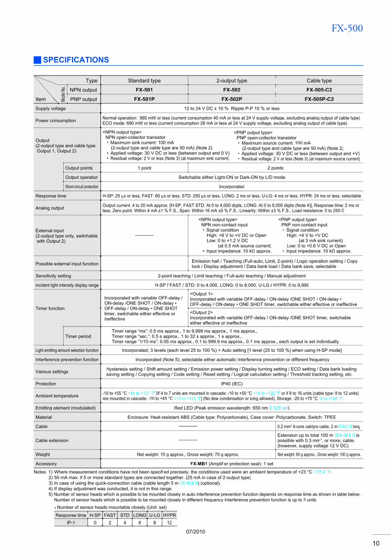
ORDER GUIDE
OPTIONS
Amplifi ers FX-501(P) and FX-502(P). Please order it separately.
Type Appearance Model No. Emittingelement Output External input
Sta
ndar
dty
pe
FX-501
Red LED
NPN open-collector transistor–
FX-501P PNP open-collector transistor
2-ou
tput
type FX-502 NPN open-collector transistor 2 outputs
IncorporatedSwitchable with Output 2
FX-502P PNP open-collector transistor 2 outputs
Cab
le ty
pe FX-505-C2 NPN open-collector transistor 2 outputsanalog output
Incorporated
FX-505P-C2 PNP open-collector transistor 2 outputsanalog output
Quick-connection cables
For FX-501(P) Quick-connection cable is not supplied with the amplifi er. Please order it separately.fi
Model No. DescriptionType
Main cable(3-core)
CN-73-C1 Length: 1 m 3.281 ft0.15 mm2 3-core cabtyre cable, with connector on one endCable outer diameter: ø3.0 mm ø0.118 in
CN-73-C2 Length: 2 m 6.562 ft
CN-73-C5 Length: 5 m 16.404 ft
Sub cable(1-core)
CN-71-C1 Length: 1 m 3.281 ft0.15 mm2 1-core cabtyre cable, with connector on one endCable outer diameter: ø3.0 mm ø0.118 in
CN-71-C2 Length: 2 m 6.562 ft
CN-71-C5 Length: 5 m 16.404 ft
Main cableCN-73-C•
Sub cableCN-71-C•
For FX-502(P) Quick-connection cable is not supplied with the amplifier. Please order it separately.fi
Model No. DescriptionType
Main cable(4-core)
CN-74-C1 Length: 1 m 3.281 ft0.15 mm2 4-core cabtyre cable, with connector on one endCable outer diameter: ø3.0 mm ø0.118 in
CN-74-C2 Length: 2 m 6.562 ft
CN-74-C5 Length: 5 m 16.404 ft
Sub cable(2-core)
CN-72-C1 Length: 1 m 3.281 ft0.15 mm2 2-core cabtyre cable, with connector on one endCable outer diameter: ø3.0 mm ø0.118 in
CN-72-C2 Length: 2 m 6.562 ft
CN-72-C5 Length: 5 m 16.404 ft
Main cableCN-74-C•
Sub cableCN-72-C•
Model No. DescriptionAppearance
MS-DIN-E
When cascading multiple amplifiers, or when it fimoves depending on the way it is installed on a DIN rail, these end plates clamp amplifi ers intofiplace on both sides. Make sure to use end plates when cascading multiple amplifi ers together.fiTwo pcs. per set
Communication window
Connector seal
End plates End plates are not supplied with the amplifi er. Please order them separately when the amplifi fiers are mounted in cascade.fi
Amplifi er mounting bracketMS-DIN-2•
Amplifi er protection sealFX-MB110 sets of 2 communication window seals and 1 connector seal
•
07/2010
FX-500
10
SPECIFICATIONS
Standard type 2-output type Cable typeType
del N
o. NPN output FX-501 FX-502 FX-505-C2
Item PNP outputMo FX-501P FX-502P FX-505P-C212 to 24 V DC ± 10 % Ripple P-P 10 % or lessSupply voltage
Power consumption Normal operation: 960 mW or less (current consumption 40 mA or less at 24 V supply voltage, excluding analog output of cable type)ECO mode: 680 mW or less (current consumption 28 mA or less at 24 V supply voltage, excluding analog output of cable type)
Output(2-output type and cable type:Output 1, Output 2)
<NPN output type>NPN open-collector transistor
Maximum sink current: 100 mA (2-output type and cable type are 50 mA) (Note 2)Applied voltage: 30 V DC or less (between output and 0 V)Residual voltage: 2 V or less (Note 3) (at maximum sink current)
•
••
<PNP output type>PNP open-collector transistor
Maximum source current: 100 mA (2-output type and cable type are 50 mA) (Note 2)Applied voltage: 30 V DC or less (between output and +V)Residual voltage: 2 V or less (Note 3) (at maximum source current)
•
••
1 point 2 pointsOutput points
Output operation Switchable either Light-ON or Dark-ON by L/D mode
Short-circuit protection Incorporated
Response time H-SP: 25 s or less, FAST: 60 s or less, STD: 250 s or less, LONG: 2 ms or less, U-LG: 4 ms or less, HYPR: 24 ms or less, selectable
Analog output Output current: 4 to 20 mA approx. [H-SP, FAST STD: At 0 to 4,000 digits, LONG: At 0 to 8,000 digits (Note 4)], Response time: 2 ms or less, Zero point: Within 4 mA ±1 % F.S., Span: Within 16 mA ±5 % F.S., Linearity: Within ±3 % F.S., Load resistance: 0 to 250
External input(2-output type only, switchable with Output 2)
–
<NPN output type>NPN non-contact input
Signal conditionHigh: +8 V to +V DC or OpenLow: 0 to +1.2 V DC
(at 0.5 mA source current)Input impedance: 10 k approx.
•
•
<PNP output type>PNP non-contact input
Signal conditionHigh: +4 V to +V DC
(at 3 mA sink current)Low: 0 to +0.6 V DC or OpenInput impedance: 10 k approx.
•
•
Possible external input function – Emission halt / Teaching (Full-auto, Limit, 2-point) / Logic operation setting / Copylock / Display adjustment / Data bank load / Data bank save, selectable
2-point teaching / Limit teaching / Full-auto teaching / Manual adjustmentSensitivity setting
Incident light intensity display range H-SP / FAST/ / STD: 0 to 4,000, LONG: 0 to 8,000, U-LG/ / HYPR: 0 to 9,999/
Timer function
Incorporated with variable OFF-delay / ON-delay /ONE SHOT / ON-delay • OFF-delay / ON-delay • ONE SHOTtimer, switchable either effective or ineffective
<Output 1>Incorporated with variable OFF-delay / ON-delay /ONE SHOT / ON-delay •OFF-delay / ON-delay • ONE SHOT timer, switchable either effective or ineffective
<Output 2>Incorporated with variable OFF-delay / ON-delay /ONE SHOT timer, switchable either effective or ineffective
Timer periodTimer range “ms”: 0.5 ms approx., 1 to 9,999 ms approx., 1 ms approx., Timer range “sec.”: 0.5 s approx., 1 to 32 s approx., 1 s approx., Timer range “1/10 ms”: 0.05 ms approx., 0.1 to 999.9 ms approx., 0.1 ms approx., each output is set individually
Light emitting amount selection function Incorporated, 3 levels (each level 25 to 100 %) + Auto setting [1 level (25 to 100 %) when using H-SP mode]
Interference prevention function Incorporated (Note 5), selectable either automatic interference prevention or different frequency
Various settings Hysteresis setting / Shift amount setting / Emission power setting / Display turning setting / ECO setting / Data bank loading saving setting / Copying setting / Code setting / Reset setting / Logical calculation setting / Threshold tracking setting, etc.
Protection IP40 (IEC)
Ambient temperature -10 to +55 °C +14 to +131 °F [If 4 to 7 units are mounted in cascade: -10 to +50 °C +14 to +122 °F or if 8 to 16 units (cable type: 8 to 12 units)are mounted in cascade: -10 to +45 °C +14 to +113 °F] (No dew condensation or icing allowed), Storage: -20 to +70 °C -4 to +158 °F
Red LED (Peak emission wavelength: 650 nmEmitting element (modulated) 0.026 mil)
Enclosure: Heat-resistant ABS (Cable type: Polycarbonate), Case cover: Polycarbonate, Switch: TPEEMaterial
Cable – 0.2 mm2 6-core cabtyre cable, 2 m 6.562 ft long
Cable extension –Extension up to total 100 m 328.084 ft ispossible with 0.3 mm2, or more, cable. (however, supply voltage 12 V DC)
Weight Net weight: 15 g approx., Gross weight: 70 g approx. Net weight: 60 g approx., Gross weight: 100 g approx.
Accessory FX-MB1 (Amplifi er protection seal): 1 setfi
Notes: 1) Where measurement conditions have not been specified precisely, the conditions used were an ambient temperature of +23 °Cfi +73.4 °F.2) 50 mA max. if 5 or more standard types are connected together. (25 mA in case of 2-output type)3) In case of using the quick-connection cable (cable length 5 m 16.404 ft) (optional).4) If display adjustment was conducted, it is not in this range.5) Number of sensor heads which is possible to be mounted closely in auto interference prevention function depends on response time as shown in table below.
Number of sensor heads which is possible to be mounted closely in different frequency Interference prevention function is up to 3 units.Number of sensor heads mountable closely (Unit: set)
Response time H-SP FAST STD LONG U-LG HYPR0IP-1 2 4 8 8 12
07/2010
FX-500
11
+–
12 to 24 V DC± 10 %
Sen
sor c
ircui
t
1
3
2
Color code of quick-connection cableTerminal No.
(Brown) +V (Note 1)
(Black) Output
100 mA max. (Note 2)
Load
User’s circuitInternal circuit
(Blue) 0 V (Note 1)
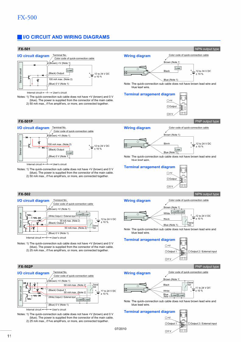
I/O CIRCUIT AND WIRING DIAGRAMS
I/O circuit diagram Wiring diagram
FX-501 NPN output type
Terminal arragement diagramNotes: 1) The quick-connection sub cable does not have +V (brown) and 0 V
(blue). The power is supplied from the connector of the main cable.2) 50 mA max., if five amplifi fiers, or more, are connected together.fi
Note: The quick-connection sub cable does not have brown lead wire andblue lead wire.
1
3
2
(Brown) +V (Note 1)
(Black) Output
(Blue) 0 V (Note 1)
100 mA max. (Note 2)
Load
Color code of quick-connection cableTerminal No.
+–
12 to 24 V DC± 10 %
User’s circuitInternal circuit
Sen
sor c
ircui
t
Note: The quick-connection sub cable does not have brown lead wire and blue lead wire.
Terminal arragement diagram
1
3
2
4
Sen
sor c
ircui
t
(White) Output 2 / External input
50 mA max. (Note 2)
Color code of quick-connection cableTerminal No.
(Brown) +V (Note 1)(
(Black) Output 1
50 mA max. (Note 2)
(Blue) 0 V (Note 1)
User’s circuitInternal circuit
LoadLoad
+–
12 to 24 V DC± 10 %
Externalinput Note: The quick-connection sub cable does not have brown lead wire and
blue lead wire.
Terminal arragement diagram
Note: The quick-connection sub cable does not have brown lead wire and blue lead wire.
Terminal arragement diagram
+–
12 to 24 V DC± 10 %
Externalinput
1
3
2
4
Sen
sor c
ircui
t
User’s circuitInternal circuit
50 mA max. (Note 2)(
LoadLoad
50 mA max. (Note 2)
Color code of quick-connection cableTerminal No.
(Brown) +V (Note 1)
(White) Output 2 / External input
(Black) Output 10
(Blue) 0 V (Note 1)
FX-501P PNP output type
I/O circuit diagram Wiring diagram
Notes: 1) The quick-connection sub cable does not have +V (brown) and 0 V (blue). The power is supplied from the connector of the main cable.
2) 50 mA max., if five amplifi fiers, or more, are connected together.fi
FX-502 NPN output type
I/O circuit diagram Wiring diagram
Notes: 1) The quick-connection sub cable does not have +V (brown) and 0 V (blue). The power is supplied from the connector of the main cable.
2) 25 mA max., if five amplifi fiers, or more, are connected together.fi
Notes: 1) The quick-connection sub cable does not have +V (brown) and 0 V(blue). The power is supplied from the connector of the main cable.
2) 25 mA max., if five amplifi fiers, or more, are connected together.fi
FX-502P PNP output type
I/O circuit diagram Wiring diagram
Load
Brown (Note 1)
Black
Blue (Note 1)
Color code of quick-connection cable
12 to 24 V DC± 10 %
+–
Load
Brown (Note 1)
Black
Blue (Note 1)
Color code of quick-connection cable
12 to 24 V DC± 10 %
+–
Color code of quick-connection cable
12 to 24 V DC± 10 %
+–
LoadLoad
Brown (Note 1)
White
Black
Blue (Note 1)( )Externalinput
Brown (Note 1)
White
Black
Blue(Note 1) LoadLoad
Color code of quick-connection cable
12 to 24 V DC± 10 %
+–
Externalinput
+V
Output
0 V
1
3
2
+V
Output
0 V
1
3
2
+V
Output 1
0 V
1
3
2 Output 2 / External input4
+V
Output 1
0 V
1
3
2 Output 2 / External input4
07/2010
FX-500
12
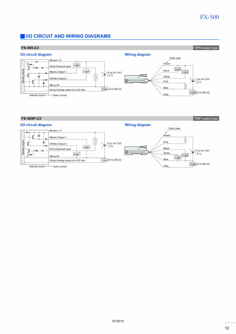
I/O CIRCUIT AND WIRING DIAGRAMS
I/O circuit diagram Wiring diagram
FX-505-C2 NPN output type
FX-505P-C2 PNP output type
I/O circuit diagram Wiring diagram
(Brown) +V
(Black) Output 1
(White) Output 2
Load
12 to 24 V DC%
Internal circuit User’s circuit
(Blue) 0V
Load
(Pink) External input
(Gray) Analog output (4 to 20 mA) (0 to 250 Ω)
+–
Load
Sen
sor c
ircui
tS
enso
r circ
uit
Internal circuit User’s circuit
Load
Load
Load (0 to 250 Ω)
+–
(Brown) +V
(Pink) External input
(Blue) 0V
(Gray) Analog output (4 to 20 mA)
(Black) Output 1
(White) Output 2 12 to 24 V DC%
Brown
Black
White
Blue
Pink
Gray
+–
Color code
LoadLoad
to 24 V DC+ 10- 15
(0 to 250 Ω)
%
Load
Pink
Black
White
Blue
Gray
Brown
Color code
LoadLoad
Load
+–
(0 to 250 Ω)
12 to 24 V DC+ 10- 15 %
07/2010
FX-500
13
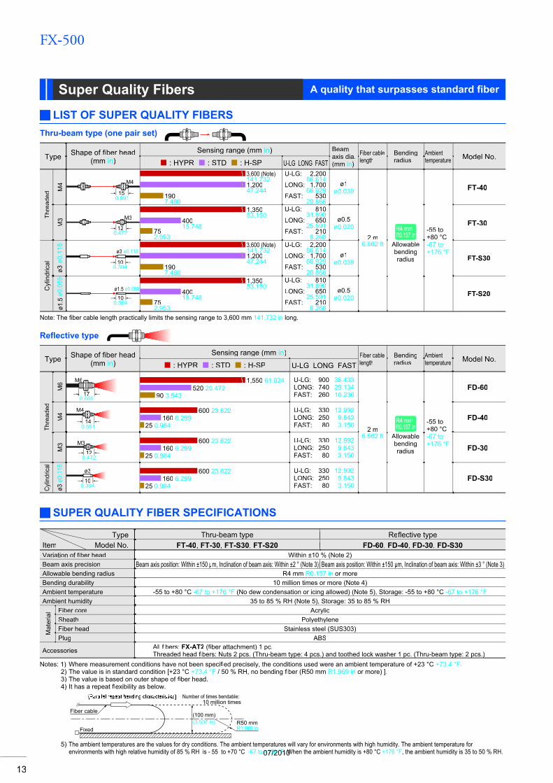
A quality that surpasses standard fi berSuper Quality Fibers
LIST OF SUPER QUALITY FIBERS
Type Shape of fi ber headfi(mm in)
Sensing range (mm in) Beamaxis dia.(mm in)
Fiber cablelength
Bendingradius
Ambienttemperature Model No.
: HYPR : STD : H-SP U-LG LONG FAST
Thre
aded
M4
150.591
M43,600 (Note), (141.7321,20047.244
1907.480
U-LG: 2,200,86.614
LONG: 1,700,66.929
FAST: 53020.866
ø1ø0.039
2 m6.562 ft
R4 mmR4 mmR0.157 inR0.157 in
Allowablebendingradius
-55 to+80 °C-67 to+176 °F
FT-40
M3 M3
120.472
1,35053.150
40015.748
752.953
U-LG: 81031.890
LONG: 65025.591
FAST: 2108.268
ø0.5ø0.020 FT-30
Cyl
indr
ical
ø3ø0
.118 ø3 ø0.118
100.394
3,600 (Note), (141.7321,20047.244
1907.480
U-LG: 2,200,86.614
LONG: 1,700,66.929
FAST: 53020.866
ø1ø0.039 FT-S30
ø1.5
ø0.0
59
100.394
ø1.5 ø0.0591,35053.150
40015.748
752.953
U-LG: 81031.890
LONG: 65025.591
FAST: 2108.268
ø0.5ø0.020 FT-S20
Thru-beam type (one pair set)
Type Shape of fiber headfi(mm in)
Sensing range (mm in) Fiber cablelength
Bendingradius
Ambienttemperature Model No.
: HYPR : STD : H-SP U-LG LONG FAST
Thre
aded
M6
170.669
M6 1,550 61.024520 20.472
90 3.543
U-LG: 900 35.433LONG: 740 29.134FAST: 260 10.236
2 m6.562 ft
R4 mmR4 mmR0.157 inR0.157 in
Allowablebendingradius
-55 to+80 °C-67 to+176 °F
FD-60
M4 M4
140.551
600 23.622160 6.299
25 0.984
U-LG: 330 12.992LONG: 250 9.843FAST: 80 3.150
FD-40
M3 M3
120.472
600 23.622160 6.299
25 0.984
U-LG: 330 12.992LONG: 250 9.843FAST: 80 3.150
FD-30
Cylin
drica
l
ø3ø0
.118
100.394
ø3 600 23.622160 6.299
25 0.984
U-LG: 330 12.992LONG: 250 9.843FAST: 80 3.150
FD-S30
Refl ective type
SUPER QUALITY FIBER SPECIFICATIONS
Type Thru-beam type Reflective typeflItem Model No. FT-40, FT-30, FT-S30, FT-S20 FD-60, FD-40, FD-30, FD-S30Variation of fi ber headfi Within ±10 % (Note 2)Beam axis precision Beam axis position: Within ±150 p m, Inclination of beam axis: Within ±2 ° (Note 3) Beam axis position: Within ±150( ) p m, Inclination of beam axis: Within ±3 ° (Note 3)( )
R4 mm Allowable bending radius R0.157 in or more10 million times or more (Note 4)Bending durability
-55 to +80 °C Ambient temperature -67 to +176 °F (No dew condensation or icing allowed) (Note 5), Storage: -55 to +80 °C -67 to +176 °F35 to 85 % RH (Note 5), Storage: 35 to 85 % RHAmbient humidity
Mat
eria
l Fiber core AcrylicSheath Polyethylene
Stainless steel (SUS303)Fiber headPlug ABS
Accessories All fibers:fi FX-AT2 (fi ber attachment) 1 pc.fiThreaded head fi bers: Nuts 2 pcs. (Thru-beam type: 4 pcs.) and toothed lock washer 1 pc. (Thru-beam type: 2 pcs.)p ( yp p ) p ( yp p )fi
Notes: 1) Where measurement conditions have not been specified precisely, the conditions used were an ambient temperature of +23 °C fi +73.4 °F.2) The value is in standard condition [+23 °C +73.4 °F / 50 % RH, no bending fiber (R50 mm fi R1.969 in or more) ].3) The value is based on outer shape of fi ber head.fi4) It has a repeat flexibility as below. fl
(100 mm)(3.937 in)
Number of times bendable:10 million times
Fixed R1.969 inR50 mm
Fiber cable
5) The ambient temperatures are the values for dry conditions. The ambient temperatures will vary for environments with high humidity. The ambient temperature for environments with high relative humidity of 85 % RH is - 55 to +70 °C -67 to +158 °F. When the ambient humidity is +80 °C +176 °F, the ambient humidity is 35 to 50 % RH.
Note: The fi ber cable length practically limits the sensing range to 3,600 mm fi 141.732 in long.
07/2010
FX-500
14
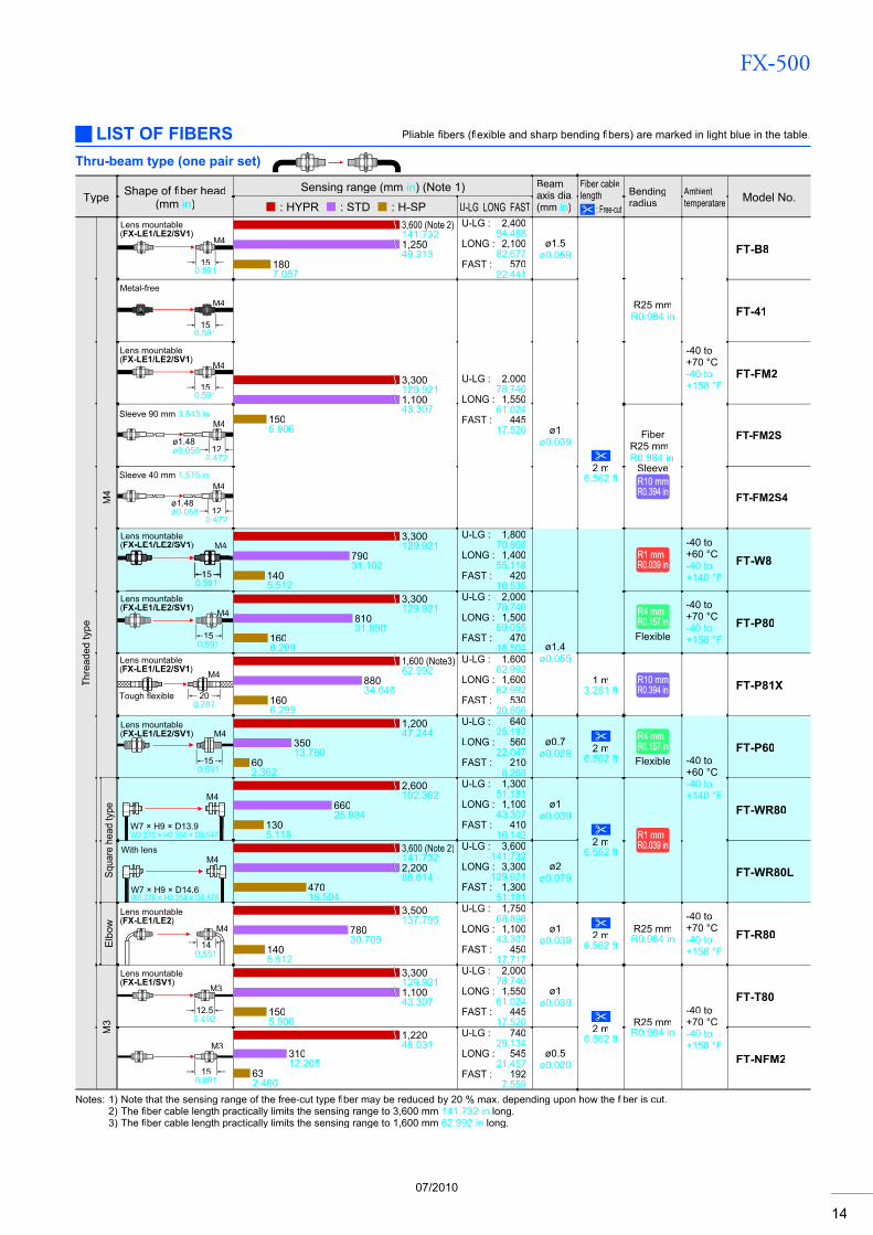
Thru-beam type (one pair set)
Type Shape of fiber headfi(mm in)
Sensing range (mm in) (Note 1) Beamaxis dia.(mm in)
Fiber cablelength
: Free-cut
Bendingradius
Ambienttemperatare Model No.
: HYPR : STD : H-SP U-LG LONG FAST
Thre
aded
type
M4
M4
150.591
Lens mountable (FX-LE1/LE2/SV1)
3,600 (Note 2)141.7321,25049.213
1807.087
U-LG : 2,40094.488
LONG : 2,10082.677
FAST : 57022.441
ø1.5ø0.059
R25 mmR0.984 in
-40 to +70 °C-40 to+158 °F
FT-B8
M4
15
Metal-free
0.591
3,300129.9211,10043.307
1505.906
U-LG : 2,00078.740
LONG : 1,55061.024
FAST : 44517.520
FT-41
M4
15
Lens mountable(FX-LE1/LE2/SV1)
0.591
FT-FM2
M4
ø1.48ø0.058
Sleeve 90 mm 3.543 in
120.472
ø1ø0.039
2 m6.562 ft
FiberR25 mmR0.984 in
SleeveR10 mmR10 mmR0.394 inR0.394 in
FT-FM2S
M4
ø1.48ø0.058
Sleeve 40 mm 1.575 in
120.472
FT-FM2S4
M4Lens mountable(FX-LE1/LE2/SV1)
3,300129.921
79031.102
1405.512
U-LG : 1,80070.866
LONG : 1,40055.118
FAST : 42016.535
R1 mmR1 mmR0.039 inR0.039 in
-40 to+60 °C-40 to+140 °F
FT-W8
M4
150.591
Lens mountable(FX-LE1/LE2/SV1)
3,300129.921
81031.890
1606.299
U-LG : 2,00078.740
LONG : 1,50059.055
FAST : 47018.504 ø1.4
ø0.055
R4 mmR4 mmR0.157 inR0.157 inFlexible
-40 to+70 °C-40 to+158 °F
FT-P80
200.787
M4Lens mountable(FX-LE1/LE2/SV1)
Tough flexible
1,600 (Note3)62.992
88034.646
1606.299
U-LG : 1,60062.992
LONG : 1,60062.992
FAST : 53020.866
1 m3.281 ft
R10 mmR10 mmR0.394 inR0.394 in FT-P81X
M4
150.591
Lens mountable(FX-LE1/LE2/SV1)
1,20047.244
35013.780
602.362
U-LG : 64025.197
LONG : 56022.047
FAST : 2108.268
ø0.7ø0.028 2 m
6.562 ft
R4 mmR4 mmR0.157 inR0.157 inFlexible -40 to
+60 °C-40 to+140 °F
FT-P60
Squa
re h
ead
type
M4
W7 × H9 × D13.9W0.276 × H0.354 × D0.547
2,600102.362
66025.984
1305.118
U-LG : 1,30051.181
LONG : 1,10043.307
FAST : 41016.142
ø1ø0.039
2 m6.562 ft
R1 mmR1 mmR0.039 inR0.039 in
FT-WR80
M4With lens
W7 × H9 × D14.6W0.276 × H0.354 × D0.575
3,600 (Note 2)141.7322,20086.614
47018.504
U-LG : 3,600141.732
LONG : 3,300129.921
FAST : 1,30051.181
ø2ø0.079 FT-WR80L
Elb
ow M4
140.551
Lens mountable(FX-LE1/LE2)
3,500137.795
78030.709
1405.512
U-LG : 1,75068.898
LONG : 1,10043.307
FAST : 45017.717
ø1ø0.039 2 m
6.562 ftR25 mmR0.984 in
-40 to+70 °C-40 to+158 °F
FT-R80
M3
M3
12.50.492
Lens mountable(FX-LE1/SV1)
3,300129.9211,10043.307
1505.906
U-LG : 2,00078.740
LONG : 1,55061.024
FAST : 44517.520
ø1ø0.039
2 m6.562 ft
R25 mmR0.984 in
-40 to+70 °C-40 to+158 °F
FT-T80
M3
150.591
1,22048.031
31012.205
632.480
U-LG : 74029.134
LONG : 54521.457
FAST : 1927.559
ø0.5ø0.020 FT-NFM2
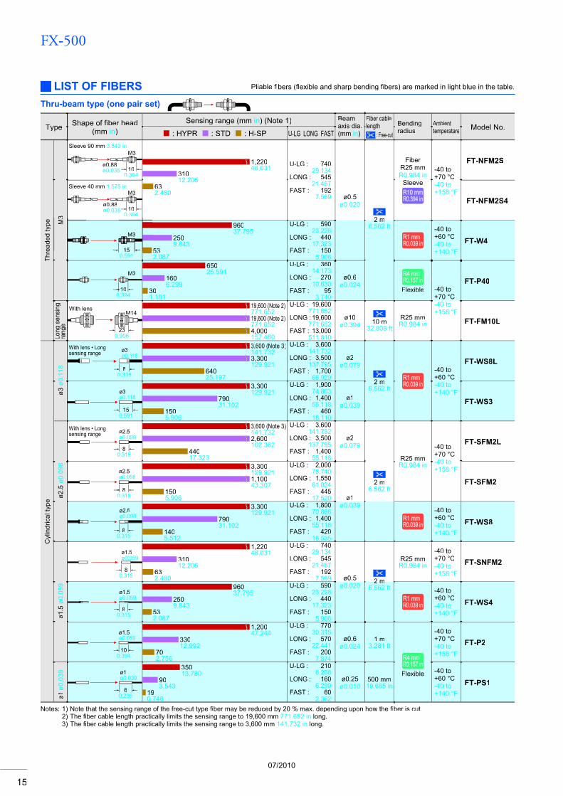
LIST OF FIBERS Pliable fibers (fi flexible and sharp bending fl fibers) are marked in light blue in the table.fi
Notes: 1) Note that the sensing range of the free-cut type fi ber may be reduced by 20 % max. depending upon how thefi fiber is cut.fi2) The fiber cable length practically limits the sensing range to 3,600 mm fi 141.732 in long.3) The fiber cable length practically limits the sensing range to 1,600 mm fi 62.992 in long.
07/2010
FX-500
15
Type Shape of fiber headfi(mm in)
Sensing range (mm in) (Note 1) Beamaxis dia.(mm in)
Fiber cablelength
: Free-cut
Bendingradius
Ambienttemperatare Model No.
: HYPR : STD : H-SP U-LG LONG FAST
Thre
aded
type
3
M3
ø0.88ø0.035
Sleeve 90 mm 3.543 in
100.394
1,22048.031
31012.205
632.480
U-LG : 74029.134
LONG : 54521.457
FAST : 1927.559
FiberR25 mmR0.984 in
SleeveR10 mmR10 mmR0.394 inR0.394 in
-40 to+70 °C-40 to+158 °F
FT-NFM2S
M3
ø0.88ø0.035
Sleeve 40 mm 1.575 in
100.394
ø0.5ø0.020
2 m2 m6.562 ft
FT-NFM2S4
150.591
96037.795
2509.843
532.087
U-LG : 59023.228
LONG : 44017.323
FAST : 1505.906
R1 mmR1 mmR0.039 inR0.039 in
-40 to+60 °C-40 to+140 °F
FT-W4
M3
100.394
65025.591
1606.299
301.181
U-LG : 36014.173
LONG : 27010.630
FAST : 953.740
ø0.6ø0.024
R4 mmR4 mmR0.157 inR0.157 inFlexible -40 to
+70 °C-40 to+158 °F
FT-P40
Long
sen
sing
rang
e
With lensM14
230.906
19,600 (Note 2)771.65219,600 (Note 2)771.6524,000157.480
U-LG : 19,600771.652
LONG : 19,600771.652
FAST : 13,000511.810
ø10ø0.394 10 m
32.808 ftR25 mmR0.984 in FT-FM10L
Cyl
indr
ical
type
ø3ø0
.118
ø3ø0.118
With lens • Long sensing range
80.315
3,600 (Note 3)141.7323,300129.921
64025.197
U-LG : 3,600141.732
LONG : 3,500137.795
FAST : 1,70066.929
ø2ø0.079
2 m6.562 ft
R1 mmR1 mmR0.039 inR0.039 in
-40 to+60 °C-40 to+140 °F
FT-WS8L
ø3ø0.118
150.591
3,300129.921
79031.102
1505.906
U-LG : 1,90074.803
LONG : 1,40055.118
FAST : 46018.110
ø1ø0.039 FT-WS3
ø2.5
ø0.0
98
80.315
With lens • Long sensing range ø2.5
ø0.098
3,600 (Note 3)141.7322,600102.362
44017.323
U-LG : 3,600141.732
LONG : 3,500137.795
FAST : 1,40055.118
ø2ø0.079
R25 mmR0.984 in
-40 to +70 °C-40 to+158 °F
FT-SFM2L
ø2.5ø0.098
80.315
3,300129.9211,10043.307
1505.906
U-LG : 2,00078.740
LONG : 1,55061.024
FAST : 44517.520 ø1
ø0.039
2 m6.562 ft
FT-SFM2
80.315
ø2.5ø0.098
3,300129.921
79031.102
1405.512
U-LG : 1,80070.866
LONG : 1,40055.118
FAST : 42016.535
R1 mmR1 mmR0.039 inR0.039 in
-40 to+60 °C-40 to+140 °F
FT-WS8
ø1.5
ø0.0
59
80.315
ø1.5ø0.059
1,22048.031
31012.205
632.480
U-LG : 74029.134
LONG : 54521.457
FAST : 1927.559 ø0.5
ø0.0202 m2 m
6.562 ft
R25 mmR0.984 in
-40 to+70 °C-40 to+158 °F
FT-SNFM2
80.315
ø1.5ø0.059
96037.795
2509.843
532.087
U-LG : 59023.228
LONG : 44017.323
FAST : 1505.906
R1 mmR1 mmR0.039 inR0.039 in
-40 to+60 °C-40 to+140 °F
FT-WS4
100.394
ø1.5ø0.059
1,20047.244
33012.992
702.756
U-LG : 77030.315
LONG : 57022.441
FAST : 2007.874
ø0.6ø0.024
1 m3.281 ft
R4 mmR4 mmR0.157 inR0.157 inFlexible
-40 to+70 °C-40 to+158 °F
FT-P2
ø1ø0
.039
60.236
ø1ø0.039
35013.780
903.543
190.748
U-LG : 2108.268
LONG : 1606.299
FAST : 602.362
ø0.25ø0.010
500 mm19.685 in
-40 to+60 °C-40 to+140 °F
FT-PS1
Thru-beam type (one pair set)
LIST OF FIBERS Pliable fi bers (fi flexible and sharp bending fl fibers) are marked in light blue in the table.fi
Notes: 1) Note that the sensing range of the free-cut type fi ber may be reduced by 20 % max. depending upon how thefi fi ber is cut.fi2) The fiber cable length practically limits the sensing range to 19,600 mmfi 771.652 in long.3) The fiber cable length practically limits the sensing range to 3,600 mm fi 141.732 in long.
07/2010
FX-500
16
Type Shape of fiber headfi(mm in)
Sensing range (mm in) (Note 1) Beamaxis dia.(mm in)
Fiber cablelength
: Free-cut
Bendingradius
Ambienttemperatare Model No.
: HYPR : STD : H-SP U-LG LONG FAST
Cyl
indr
ical
type
Sid
e-vi
ew
ø4 ø0.157
3325
0.9840.118
3,600 (Note 2)141.7323,500137.795
85033.465
U-LG : 3,600141.732
LONG : 3,600141.732
FAST : 2,40094.488
ø2.5ø0.098
2 m6.562 ft
R25 mmR0.984 in
-40 to+60 °C-40 to+140 °F
FT-V10
Sleeve part cannot be bent.
0.81520
0.5910.787
ø1.5ø0.059
0.031
ø2.5ø0.098
2,20086.614
57022.441
1003.937
U-LG : 1,30051.181
LONG : 1,00039.370
FAST : 36014.173
ø1.1ø0.043
-20 to+70 °C-4 to+158 °F
FT-SFM2SV2
0.66
ø1ø0.039
ø2ø0.079
0.024Sleeve partcannot be bent.
15200.5910.787
1,20047.244
30011.811
903.543
U-LG : 60023.622
LONG : 49019.291
FAST : 2007.874
ø0.8ø0.031
1 m3.281 ft
-20 to+60 °C-4 to+140 °F
FT-V22
0.6Sleeve partcannot be bent.
15100.024
0.5910.394
ø1ø0.039
ø2.5ø0.098
79031.102
2007.874
401.575
U-LG : 45017.717
LONG : 36014.173
FAST : 1305.118
ø0.55ø0.022
2 m2 m6.562 ft
-40 to+60 °C-40 to+140 °F
FT-V41
1Sleeve partcannot be bent.
150.591
150.591
0.039
ø1ø0.039
ø2ø0.079
38014.961
1003.937
200.787
U-LG : 2208.661
LONG : 1706.693
FAST : 602.362
ø0.5ø0.020
R1 mmR1 mmR0.039 inR0.039 in FT-WV42
Rec
tang
ular
Com
pact
Easy mounting • Top sensing
W3 × H8 × D12W0.118 × H0.315 × D0.472
3,600 (Note 2)141.7323,300129.921
63024.803
U-LG : 3,600141.732
LONG : 3,500137.795
FAST : 1,80070.866
2.2 × 30.087
×0.118
2 m6.562 ft
R1 mmR1 mmR0.039 inR0.039 in
-40 to+60 °C-40 to+140 °F
FT-WZ8H
3,600 (Note 2)141.7322,10082.677
41016.142
U-LG : 3,600141.732
LONG : 3,300129.921
FAST : 1,30051.181
R4 mmR4 mmR0.157 inR0.157 inFlexible
FT-Z8H
Easy mounting • Side sensing
W3 × H12 × D8W0.118 × H0.472 × D0.315
3,600 (Note 2)141.7323,400133.858
59023.228
U-LG : 3,600141.732
LONG : 3,600141.732
FAST : 1,85072.835
R1 mmR1 mmR0.039 inR0.039 in FT-WZ8E
3,600 (Note 2)141.7322,00078.740
49019.291
U-LG : 3,600141.732
LONG : 3,300129.921
FAST : 1,30051.181
R4 mmR4 mmR0.157 inR0.157 inFlexible
FT-Z8E
Easy mounting • Front sensing
W8.5 × H12 × D3W0.335 × H0.472 × D0.118
3,600 (Note 2)(141.7321,30051.181
28011.024
U-LG : 3,100122.047
LONG : 2,30090.551
FAST : 83032.677
R1 mmR1 mmR0.039 inR0.039 in FT-WZ8
3,600 (Note 2)141.7321,20047.244
2509.843
U-LG : 2,700106.299
LONG : 2,10082.677
FAST : 75029.528
R4 mmR4 mmR0.157 inR0.157 inFlexible
FT-Z8
Front sensing
W10 × H7 × D2W0.394 × H0.276 × D0.079
1,600 (Note 3)62.992
53020.866
1003.937
U-LG : 1,10043.307
LONG : 90035.433
FAST : 33012.992
ø1.5ø0.059
1 m3.281 ft
R1 mmR1 mmR0.039 inR0.039 in
FT-WZ4
Fiber bending type
W2 × H10 × D10 W0.079 × H0.394 × D0.394
31.4962108.268
401.575
U-LG : 46018.110
LONG : 37014.567
FAST : 1305.118
ø0.5ø0.020 FT-WZ4HB
Front sensing
W14 × H7 × D3.5W0.551 × H0.276 × D0.138
3,500137.7951,40055.118
29011.417
U-LG : 3,300129.921
LONG : 2,30090.551
FAST : 89035.039
ø1.5ø0.059
2 m6.562 ft
FT-WZ7
Fiber bending type
W3.5 × H14 × D11 W0.138 × H0.551 × D0.433
3,500137.795
79031.102
1606.299
U-LG : 1,70066.929
LONG : 1,30051.181
FAST : 49019.291
ø1ø0.039 FT-WZ7HB
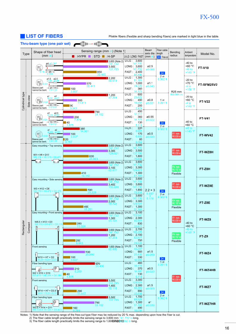
Notes: 1) Note that the sensing range of the free-cut type fi ber may be reduced by 20 % max. depending upon how thefi fiber is cut.fi2) The fiber cable length practically limits the sensing range to 3,600 mm fi 141.732 in long.3) The fiber cable length practically limits the sensing range to 1,600 mm fi 62.992 in long.
Thru-beam type (one pair set)
LIST OF FIBERS Pliable fibers (fi flexible and sharp bending fl fibers) are marked in light blue in the table.fi
07/2010
FX-500
17
Type Shape of fiber headfi(mm in)
Sensing range (mm in) (Note 1) Beamaxis dia.(mm in)
Fiber cablelength
: Free-cut
Bendingradius
Ambienttemperatare Model No.
: HYPR : STD : H-SP U-LG LONG FAST
Spe
cial
Nar
row
bea
m
200.787
ø3.7ø0.146
ø3.5ø0.138
3,600 (Note 2)141.7323,600 (Note 2)141.732
75029.528
U-LG : 3,600141.732
LONG : 3,600141.732
FAST : 2,700106.299
ø2.2ø0.087
R25 mmR0.984 in FT-K8
Side-view type with small light dispersion
ø4 ø0.157
250.984
330.118
3,600 (Note 2)141.7323,600 (Note 2)141.732
76029.921
U-LG : 3,600141.732
LONG : 3,600141.732
FAST : 2,40094.488 ø2.5
ø0.0982 m2 m
6.562 ft
R1 mmR1 mmR0.039 inR0.039 in -40 to
+60 °C-40 to+140 °F
FT-WKV8
3,600 (Note 2)141.7323,600 (Note 2)141.732
75029.528
U-LG : 3,600141.732
LONG : 3,600141.732
FAST : 2,700106.299
R25 mmR0.984 in FT-KV8
2
200.787
W2 × H1.5 × D20W0.079 × H0.059 × D0.787
0.079
2,40094.488
54021.260
1606.299
U-LG : 1,10043.307
LONG : 85033.465
FAST : 43016.929
ø1ø0.039
R10 mmR10 mmR0.394 inR0.394 in FT-KV1
Wid
e be
am
Wide area sensing
3,600 (Note 2)141.732
, ( )3,600 (Note 2)141.7323,300129.921
U-LG : 3,600141.732
,LONG : 3,600141.732
FAST : 3,600141.732
3.2 × 320.126
×1.260
R1 mmR1 mmR0.039 inR0.039 in
-40 to+55 °C-40 to+131 °F
FT-WA30
Sensing width32 mm 1.260 in
W5 × H69 × D20W0.197 × H2.717 × D0.787
2 m2 m6.562 ft
R10 mmR10 mmR0.394 inR0.394 in
-40 to+60 °C-40 to+140 °F
FT-A30
Wide area sensing 3,600 (Note 2)141.7323,600 (Note 2)141.732
98038.583
U-LG : 3,600141.732
LONG : 3,600141.732
FAST : 3,300129.921
2.2 × 110.087
×0.433
R1 mmR1 mmR0.039 inR0.039 in
-40 to+55 °C-40 to+131 °F
FT-WA8
W4.2 × H31 × D13.5W0.165 × H1.220 × D0.531
Sensing width11 mm 0.433in
3,600 (Note 2)141.7323,500137.7951,20047.244
U-LG : 3,600141.732
LONG : 3,600141.732
FAST : 3,300129.921
R10 mmR10 mmR0.394 inR0.394 in
-40 to+70 °C-40 to+158 °F
FT-A8
Arr
ay
Top sensing
W5 × H15 × D15 W0.197 × H0.591 × D0.591
3,500137.795
86033.858
1606.299
U-LG : 2,00078.740
LONG : 1,50059.055
FAST : 49019.291
0.265×
5.50.010
×0.217
2 m6.562 ft
R25 mmR0.984 in
-40 to+70 °C-40 to+158 °F
FT-AFM2
Side sensing
W5 × H15 × D15W0.197 × H0.591 × D0.591
FT-AFM2E
Hea
t-res
ista
nt
350 °C 662 °FLens mo
M4
301.181
1,20047.244
43016.929
803.150
U-LG : 88034.646
LONG : 67026.378
FAST : 2509.843
ø1.2ø0.047
2 m6.562 ft
R25 mmR0.984 in
-60 to+350 °C-76 to+662 °F
FT-H35-M2
350 °C 662 °FSleeve 60 mm 2.362 in
M4
271.063
ø2.1ø0.083
FiberR25 mm R0.984 in
SleeveR10 mmR10 mmR0.394 inR0.394 in
FT-H35-M2S6
M4 230.906
Allows flexible wiring200 °C 392 °FLens mountable (FX-LE1/LE2/SV1)
1,600 (Note 3)62.992
47018.504
903.543
U-LG : 1,00039.370
LONG : 84033.071
FAST : 30011.811
ø0.8ø0.031
1 m3.281 ft
R10 mmR10 mmR0.394 inR0.394 in
-60 to+200 °C-76 to+392 °F
FT-H20W-M1
200 °C 392 °FLens mountable (FX-LE1/LE2/SV1)
M4 230.906
1,600 (Note 3)62.992
54021.260
1104.331
U-LG : 1,30051.181
LONG : 96037.795
FAST : 33012.992
ø1.2ø0.047
R25 mmR0.984 in
FT-H20-M1
130 °C 266 °FLens mountable (FX-LE2 only)
M4 160.630
3,300129.921
70027.559
1405.512
U-LG : 1,90074.803
LONG : 1,30051.181
FAST : 41016.142
ø1.5ø0.059 2 m
6.562 ft
-60 to+130 °C-76 to+266 °F
FT-H13-FM2
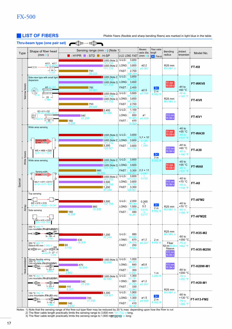
Notes: 1) Note that the sensing range of the free-cut type fi ber may be reduced by 20 % max. depending upon how thefi fi ber is cut.fi2) The fiber cable length practically limits the sensing range to 3,600 mm fi 141.732 in long.3) The fiber cable length practically limits the sensing range to 1,600 mm fi 62.992 in long.
Thru-beam type (one pair set)
LIST OF FIBERS Pliable fi bers (fi flexible and sharp bending fl fibers) are marked in light blue in the table.fi
07/2010
FX-500
18
Type Shape of fiber headfi(mm in)
Sensing range (mm in) (Note 1) Beamaxis dia.(mm in)
Fiber cablelength
: Free-cut
Bendingradius
Ambienttemperatare Model No.
: HYPR : STD : H-SP U-LG LONG FAST
Spe
cial
Hea
t-res
ista
nt •
Join
t
Lens mountable(FX-LE1/LE2/SV1)
M4
230.906
1,60062.992
47018.504
903.543
U-LG : 1,00039.370
LONG : 79031.102
FAST : 30011.811
ø1.2ø0.047
200 mm 7.874 in(Note 2)
Heat-resistant
fiberfiR18 mmR0.709 in(Note 3)
-60 to+200 °C-76 to+392 °F
FT-H20-J20-S(Note 4)
300 mm 11.811 in(Note 2)
FT-H20-J30-S(Note 4)
500 mm 19.685 in(Note 2)
FT-H20-J50-S(Note 4)
Side-view
240.945
ø3.8ø0.150ø4ø0.157
2,10082.677
60023.622
1204.724
U-LG : 1,30051.181
LONG : 98038.583
FAST : 39015.354
500 mm 19.685 in(Note 2)
FT-H20-VJ50-S(Note 4)
800 mm 31.496 in(Note 2)
FT-H20-VJ80-S(Note 4)
Che
mic
al-r
esis
tant
Easy mounting · Rectangular headSEMI S2 compliant
W7 × H15 × D13W0.276 × H0.591 × D0.512
3,600 (Note 5)141.7323,100122.047
47018.504
U-LG : 3,600141.732
LONG : 3,600141.732
FAST : 1,90074.803
ø3.7ø0.146
2 m6.562 ft
R25 mmR0.984 in
0 to +60 °C32 to+140 °F
FT-Z802Y
115 °C 239 °F
(25)(0.984)
ø5.5 ø0.217
3,600 (Note 5)141.7323,600 (Note 5)141.732
74029.134
U-LG : 3,600141.732
LONG : 3,600141.732
FAST : 2,30090.551
2 m6.562 ft(Note 6)
R30 mmR1.181 in
-40 to+115 °C-40 to+239 °F
FT-HL80Y
ø5.5 ø0.217
(25)(0.984)
3,600 (Note 5)141.7323,600 (Note 5)141.732
92036.220
U-LG : 3,600141.732
LONG : 3,600141.732
FAST : 2,800110.236
-40 to+70 °C-40 to+158 °F
FT-L80Y
ø5.5 ø0.217
(25)(0.984)
Side-view 3,600 (Note 5)141.7321,30051.181
2409.449
U-LG : 2,800110.236
LONG : 2,20086.614
FAST : 80031.496
ø2.8ø0.110 FT-V80Y
Vac
uum
-re
sist
ant 300 °C 572 °F
Lens mountable (FV-LE1/SV2 only)M4
301.181
1,00039.370
27010.630
552.165
U-LG : 59023.228
LONG : 47018.504
FAST : 1606.299
ø1.2ø0.047
1 m3.281 ft
R18 mmR0.709 in
-30 to+300 °C-22 to+572 °F
FT-H30-M1V-S(Note 7)
Thru-beam type (one pair set)
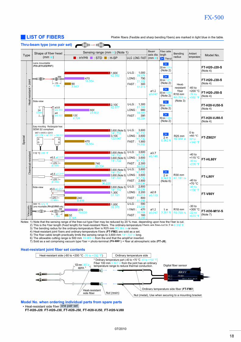
LIST OF FIBERS Pliable fibers (fi flexible and sharp bending fl fibers) are marked in light blue in the table.fi
Notes: 1) Note that the sensing range of the free-cut type fi ber may be reduced by 20 % max. depending upon how thefi fiber is cut.fi2) This is the fiber length (fi fi xed length) for heat-resistantfi fibers. The ordinary-temperature fi fi bers are free-cut to 2 mfi 6.562 ft.3) The bending radius for the ordinary-temperature fiber is R25 mm fi R0.984 in or more.4) Heat-resistant joint fibers and ordinary-temperaturefi fibers (fi FT-FM2) are sold as a set.5) The fiber cable length practically limits the sensing range to 3,600 mm fi 141.732 in long.6) The allowable cutting range is 500 mm 19.685 in from the end that the amplifier inserted.fi7) Sold as a set comprising vacuum type fi ber + photo-terminal (fi FV-BR1) + fiber at atmospheric side (fi FT-J8).
Heat-resistant joint fi ber set contents
Model No. when ordering individual parts from spare partsHeat-resistant side fi ber fi one pair setFT-H20-J20, FT-H20-J30, FT-H20-J50, FT-H20-VJ50, FT-H20-VJ80
•
Ordinary temperature side fiber (FT-FM2)
Digital fiber sensor
Heat-resistant side (-60 to +200 °C -76 to +392 °F)
100 mm 3.937 inapprox. *
Ordinary temperature side
Heat-resistantside fiber Nut (resin)
Nut (metal), Use when securing to a mounting bracket.
* Ordinary temperature part (-40 to +70 °C -40 to +158 °F)Fiber 100 mm 3.937 in from the joint has an ordinary temperature range to reduce thermal conduction.
07/2010
FX-500
19
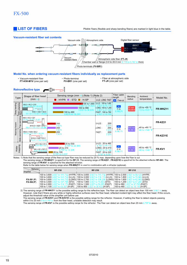
Retrorefl ective type
Notes: 1) Note that the sensing range of the free-cut type fi ber may be reduced by 20 % max. depending upon how thefi fi ber is cut.fiThe sensing range of FR-WKZ11 is specifi ed for the fi RF-13. The sensing range of FR-KZ21, FR-KZ21E is specifi ed for the attached refi fl ector fl RF-003. The sensing range of FR-KV1 is specifi ed for the attached refi flector.flRefer to the table below for sensing range when FR-WKZ11 is used in combination with a reflector (optional).fl
Refrector RF-230 RF-220 RF-210Amplifi erfi
FX-501(P)FX-502(P)
100 to 3,600 3.937 to 141.732 (HYPR)100 to 3,600 3.937 to 141.732 (U-LG)100 to 3,600 3.937 to 141.732 (LONG)100 to 3,500 3.937 to 137.795 (STD)100 to 2,900 3.937 to 114.173 (FAST)100 to 1,100 3.937 to 43.307 (H-SP)
100 to 3,600 3.937 to 141.732 (HYPR)100 to 3,000 3.937 to 118.110 (U-LG)100 to 2,700 3.937 to 106.299 (LONG)100 to 1,900 3.937 to 74.803 (STD)100 to 1,500 3.937 to 59.055 (FAST)100 to 900 3.937 to 35.433 (H-SP)
100 to 2,500 3.937 to 98.425 (HYPR)100 to 1,800 3.937 to 70.866 (U-LG)100 to 1,600 3.937 to 62.992 (LONG)100 to 1,200 3.937 to 47.244 (STD)100 to 960 3.937 to 37.795 (FAST)100 to 460 3.937 to 18.110 (H-SP)
2) The sensing range of FR-WKZ11 is the possible setting range for the refl ective tape. The fl fi ber can detect an object less than 100 mmfi 3.937 in away. However, note that if there are any white or highly-refl ective surfaces near the fl fiber head, refi flected incident light may affect thefl fi ber head. If this occurs,fiadjust the threshold value of the amplifi er unit before use.fiThe sensing range of FR-KZ21 and FR-KZ21E is the possible setting range for the refl ector. However, if setting the fl fi ber to detect objects passingfiwithin 0 to 20 mm 0 to 0.787 in from the fiber head, unstable detection may result.fiThe sensing range of FR-KV1 is the possible setting range for the refl ector. Thefl fiber can detect an object less than 20 mmfi 0.787 in away.
Type Shape of fiber headfi(mm in)
Sensing range (mm in) (Note 1) (Note 2) Fiber cablelength
: Free-cut
Bendingradius
Ambienttemperatare Model No.
: HYPR : STD : H-SP U-LG LONG FAST
Shar
p be
nding
With
pola
rizing
filter
spfi
W9.5 × H5.2 × D15 W0.374 × H0.205 × D0.591
W30 × H30 × D0.5 W1.181 × H1.181 × D0.020
100 to 1,9003.937 to 74.803
100 to 9903.937 to 38.976
100 to 4903.9370 to 19.291
U-LG : 100 to 1,4003.937 to 55.118
LONG : 100 to 1,2003.937 to 47.244
FAST : 100 to 7803.937 to 30.709
2 m6.562 ft
R1 mmR1 mmR0.039 inR0.039 in
-25 to +55 °C-13 to +131 °F FR-WKZ11
Nar
row
bea
m
Top
sens
ing W9.5 × H5.2 × D21
W0.374 × H0.205 × D0.827
W10.6 × H28 × D10.1W0.417 × H1.102 × D0.398
2007.8742007.8742007.874
U-LG : 2007.874
LONG : 2007.874
FAST : 2007.874
2 m6.562 ft
R10 mmR10 mmR0.394 inR0.394 in
-40 to +60 °C-40 to +140 °F
FR-KZ21
Sid
e se
nsin
g
W10.6 × H28 × D10.1W0.417 × H1.102 × D0.398
W9.5 × H25× D5.2 W0.374 × H0.984 × D0.205
FR-KZ21E
Waf
erm
appi
ng
W4 × H2 × D21.5W0.157 × H0.079 × D0.846
W7.5 × H2.2 × D11.2W0.295 × H0.087 × D0.441
20 to 5300.787 to 20.866
20 to 3100.787 to 12.205
20 to 1000.787 to 3.937
U-LG : 20 to 4600.787 to 18.110
LONG : 20 to 4100.787 to 16.142
FAST : 20 to 2200.787 to 8.661
2 m6.562 ft
R10 mmR10 mmR0.394 inR0.394 in
-40 to +60 °C-40 to +140 °F FR-KV1
Vacuum-resistant fi ber set contents
LIST OF FIBERS Pliable fi bers (fi flexible and sharp bending fl fibers) are marked in light blue in the table.fi
Atmospheric side Vacuum side
Vacuumresistant fibers
Photo-terminals (FV-BR1)
Chamber wall or flange (3.0 to 20.0 mmC 0.118 to 0.787 in thick)Atmospheric side fiber (FT-J8)
Digital fiber sensor
Model No. when ordering vacuum-resistant fi bers individually as replacement partsfi
FT-H30-M1V (one pair set)• Photo-terminalVacuum-resistant fi berfi
FV-BR1 (one pair set)Fiber at atmospheric sideFT-J8 (one pair set)
•
07/2010
FX-500
20
Type Shape of fiber headfi(mm in)
Sensing range (mm in) (Note 1) (Note 2) Fiber cablelength
: Free-cut
Bendingradius
Ambienttemperatare Model No.
: HYPR : STD : H-SP U-LG LONG FAST
Thre
aded
type
M6
M6
150.591
1,45057.087
49019.291
1003.937
U-LG : 96037.795
LONG : 86033.858
FAST : 33012.992
R25 mmR0.984 in
-40 to +70 °C-40 to +158 °F
FD-B8
Metal-free • CoaxialM6
200.787
1,00039.370
42016.535
602.362
U-LG : 68026.772
LONG : 60023.622
FAST : 2007.874
FD-G60
CoaxialM6
200.787
1,40055.118
42016.535
602.362
U-LG : 80031.496
LONG : 65025.591
FAST : 2007.874
FD-FM2
Sleeve 90 mm 3.543 in
200.787
M6
ø2.5 ø0.098 1,10043.307
38014.961
702.756
U-LG : 70027.559
LONG : 54021.260
FAST : 2208.661
2 m6.562 ft
FiberR25 mmR0.984 in
SleeveR10 mmR10 mmR0.394 inR0.394 in
FD-FM2S
Sleeve 40 mm 1.575 in
200.787
M6
ø2.5 ø0.098FD-FM2S4
87034.252
2509.843
451.772
U-LG : 56022.047
LONG : 42016.535
FAST : 1405.512
R1 mmR1 mmR0.039 inR0.039 in
-40 to +60 °C-40 to +140 °F FD-W8
M6
150.591
82032.283
28011.024
552.165
U-LG : 61024.016
LONG : 48018.898
FAST : 1606.299
R4 mmR4 mmR0.157 inR0.157 inFlexible
FD-P80
Tough flexiblefl
M6
150.591
45017.717
27010.630
501.969
U-LG : 37014.567
LONG : 33012.992
FAST : 1606.299
1 m3.281 ft
R10 mmR10 mmR0.394 inR0.394 in
-40 to +70 °C-40 to +158 °F FD-P81X
Elb
ow
M6
150.591
89035.039
2208.661
401.575
U-LG : 50019.685
LONG : 37014.567
FAST : 1305.118
2 m6.562 ft
R25 mmR0.984 in FD-R80
M4
M4
120.472
1,10043.307
38014.961
702.756
U-LG : 70027.559
LONG : 54021.260
FAST : 2208.661 R25 mm
R0.984 in
-40 to +70 °C-40 to +158 °F
FD-T80
M4
170.669
51020.079
1204.724
220.866
U-LG : 28011.024
LONG : 2158.465
FAST : 702.756
FD-NFM2
Sleeve 90 mm 3.543 in
120.472
M4ø1.48 ø0.058
2 m6.562 ft
FiberR25 mmR0.984 in
SleeveR10 mmR10 mmR0.394 inR0.394 in
FD-NFM2S
Sleeve 40 mm 1.575 in
120.472
M4
ø1.48 ø0.058FD-NFM2S4
Sleeve 40 mm 1.575 in
M4
.48
.058
33012.992
803.150
120.472
U-LG : 1807.087
LONG : 1405.512
FAST : 451.772
FiberR1 mmR1 mmR0.039 inR0.039 inSleeveR10 mmR10 mmR0.394 inR0.394 in -40 to +60 °C
-40 to +140 °F
FD-W44
87034.252
2509.843
451.772
U-LG : 56022.047
LONG : 42016.535
FAST : 1405.512
R1 mmR1 mmR0.039 inR0.039 in FD-WT8
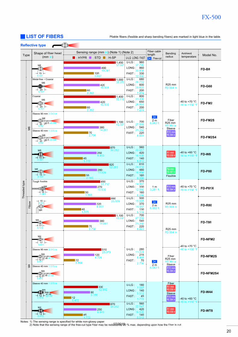
Refl ective type
Notes: 1) The sensing range is specifi ed for white non-glossy paper.fi2) Note that the sensing range of the free-cut type fi ber may be reduced by 20 % max. depending upon how thefi fiber is cut.fi
LIST OF FIBERS Pliable fibers (fi flexible and sharp bending fl fibers) are marked in light blue in the table.fi
07/2010
FX-500
21
Type Shape of fiber headfi(mm in)
Sensing range (mm in) (Note 1) (Note 2) Fiber cablelength
: Free-cut
Bendingradius
Ambienttemperatare Model No.
: HYPR : STD : H-SP U-LG LONG FAST
Thre
aded
type
M4
Minute objects can be detecteddue to the small spot beam.Coaxial • Lens mountable(FX-MR1/MR2/MR3/MR5/MR6)
M4
250.984
59023.228
1505.906
250.984
U-LG : 34013.386
LONG : 28011.024
FAST : 903.543
R2 mmR2 mmR0.079 inR0.079 in
-40 to +60 °C-40 to +140 °F FD-WG4
55021.654
1405.512
271.063
U-LG : 33012.992
LONG : 27010.630
FAST : 803.150
2 m6.562 ft
R25 mmR0.984 in
-40 to +70 °C-40 to +158 °F
FD-G4
Metal-f
M
250.984
FD-G40
M4
150.591
49019.291
1204.724
220.866
U-LG : 2509.843
LONG : 1907.480
FAST : 752.953
R4 mmR4 mmR0.157 inR0.157 inFlexible
-40 to +60 °C-40 to +140 °F FD-P60
M3
Small diameterM3
120.472
51020.079
1204.724
220.866
U-LG : 28011.024
LONG : 2158.465
FAST : 702.756
R25 mmR0.984 in
-40 to +70 °C-40 to +158 °F FD-T40
M3
10.4
33012.992
803.150
120.472
U-LG : 1807.087
LONG : 1405.512
FAST : 451.772 2 m
6.562 ft
R1 mmR1 mmR0.039 inR0.039 in
-40 to +60 °C-40 to +140 °F FD-WT4
M3
120.472
1907.480
451.772
70.276
U-LG : 1003.937
LONG : 853.346
FAST : 200.787
R4 mmR4 mmR0.157 inR0.157 inFlexible
-40 to +70 °C-40 to +158 °F FD-P40
Lens mountable (FX-MR3, FX-MR6)Coaxial
M3
170.669
55021.654
1405.512
271.063
U-LG : 33012.992
LONG : 27010.630
FAST : 803.150
R25 mmR0.984 in
-40 to +60 °C-40 to +140 °F
FD-G6
Tough flexibleflLens mountable (FX-MR3, FX-MR6)Coaxial M3
180.709
63024.803
1706.693
271.063
U-LG : 37014.567
LONG : 31012.205
FAST : 953.740
1 m 3.281 ft(Note 3)
R10 mmR10 mmR0.394 inR0.394 in FD-G6X
High precisionLens mountable (FX-MR3, FX-MR6)Coaxial M3
170.669
1706.693
401.575
7.50.295
U-LG : 1003.937
LONG : 803.150
FAST : 240.945
500 mm19.685 in
R25 mmR0.984 in
-20 to +60 °C-4 to +140 °F
FD-EG1
High precisionLens mountable (FX-MR3, FX-MR6)Coaxial M3
170.669
Light emitting fiber element ø0.175 ø0.007
1305.118
240.945
30.118
U-LG : 1003.937
LONG : 803.150
FAST : 190.748 R10 mmR10 mm
R0.394 inR0.394 in
FD-EG2
High precisionLens mountable (FX-MR3, FX-MR6)Coaxial M3
170.669
Light emitting fiber element ø0.125 ø0.005
853.346
200.787
3.50.138
U-LG : 451.772
LONG : 351.378
FAST : 120.472
FD-EG3
CoaxialM3 ø0.8 ø0.031
15150.5910.591
Sleeve part cannot be bent.
1907.480
501.969
90.354
U-LG : 1104.331
LONG : 903.543
FAST : 281.102
1 m3.281 ft
R25 mmR0.984 in FD-ENM1S1
Cyl
indr
ical
type
ø3ø0
.118
ø3 ø0.118
150.591
1,10043.307
38014.961
702.756
U-LG : 70027.559
LONG : 54021.260
FAST : 2208.661 2 m2 m
6.562 ft
R25 mmR0.984 in
-40 to +70 °C-40 to +158 °F FD-S80
ø3 ø0.118
150.591
96037.795
2509.843
451.772
U-LG : 55021.654
LONG : 41016.142
FAST : 1405.512
R1 mmR1 mmR0.039 inR0.039 in
-40 to +60 °C-40 to +140 °F FD-WS8
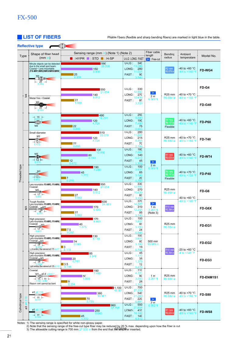
Notes: 1) The sensing range is specifi ed for white non-glossy paper.fi2) Note that the sensing range of the free-cut type fi ber may be reduced by 20 % max. depending upon how thefi fiber is cut.fi3) The allowable cutting range is 700 mm 27.559 in from the end that the amplifier inserted.fi
LIST OF FIBERS Pliable fi bers (fi flexible and sharp bending fl fibers) are marked in light blue in the table.fi
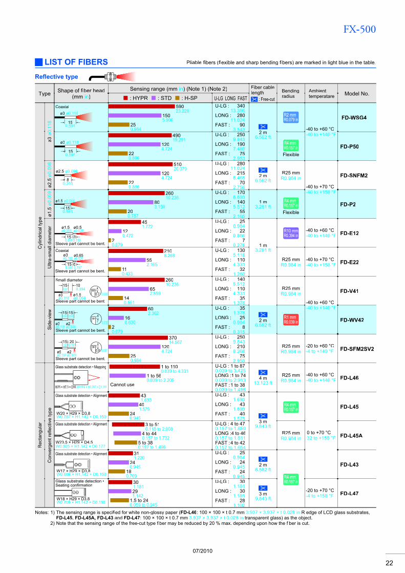
Refl ective type
07/2010
FX-500
22
Type Shape of fiber headfi(mm in)
Sensing range (mm in) (Note 1) (Note 2) Fiber cablelength
: Free-cut
Bendingradius
Ambienttemperatare Model No.
: HYPR : STD : H-SP U-LG LONG FAST
Cyl
indr
ical
type
ø3ø0
.118
Coaxialø3 ø0.118
150.591
59023.228
1505.906
250.984
U-LG : 34013.386
LONG : 28011.024
FAST : 903.543 2 m
6.562 ft
R2 mmR2 mmR0.079 inR0.079 in
-40 to +60 °C-40 to +140 °F
FD-WSG4
ø3 ø0.118
150.591
49019.291
1204.724
220.866
U-LG : 2509.843
LONG : 1907.480
FAST : 752.953
R4 mmR4 mmR0.157 inR0.157 inFlexible
FD-P50
ø2.5
ø0.0
98
ø2.5 ø0.098
80.315
51020.079
1204.724
220.866
U-LG : 28011.024
LONG : 2158.465
FAST : 702.756
2 m6.562 ft
R25 mmR0.984 in
-40 to +70 °C-40 to +158 °F
FD-SNFM2
ø1.5
ø0.0
59
ø1.5 ø0.059
150.591
26010.236
803.150
200.787
U-LG : 1706.693
LONG : 1405.512
FAST : 552.165
1 m3.281 ft
R4 mmR4 mmR0.157 inR0.157 inFlexible
FD-P2
Ultr
a-sm
all d
iam
eter
Sleeve part cannot be bent.30.118
150.591
ø1.5ø0.059
ø0.5ø0.020
451.772
120.472
20.079
U-LG : 250.984
LONG : 220.866
FAST : 70.276 1 m
3.281 ft
R10 mmR10 mmR0.394 inR0.394 in
-40 to +60 °C-40 to +140 °F FD-E12
Coaxial
Sleeve part cannot be bent.5150.1970.591
ø3ø0.118
ø0.65ø0.026
2108.268
552.165
110.433
U-LG : 1305.118
LONG : 1104.331
FAST : 321.260
R25 mmR0.984 in
-40 to +70 °C-40 to +158 °F FD-E22
Sid
e-vi
ew
Small diameter150.591
Sleeve part cannot be bent.ø1.5ø0.059
ø3ø0.118ll
0.77 0.028
100.394
26010.236
652.559
140.551
U-LG : 1405.512
LONG : 1104.331
FAST : 351.378
R25 mmR0.984 in
-40 to +60 °C-40 to +140 °F
FD-V41
15150.5910.591
Sleeve part cannot be bent.ø3ø0.118
1 0.039ø2ø0.079
602.362
160.630
20.079
U-LG : 351.378
LONG : 250.984
FAST : 80.315
2 m6.562 ft
R1 mmR1 mmR0.039 inR0.039 in FD-WV42
20
Sleeve part cannot be bent.ø2ø0.079
150.591 0.787
ø5ø0.197
0.88 0.031
37014.567
1204.724
250.984
U-LG : 2509.843
LONG : 2108.268
FAST : 752.953
R25 mmR0.984 in
-20 to +60 °C-4 to +140 °F FD-SFM2SV2
Rec
tang
ular
Con
verg
ent r
efl e
ctiv
e ty
pefl
Glass substrate detection • Mapping
W25 × H7.3 × D30 W0.984 × H0.287 × D1.181
1 to 1100.039 to 4.331
1 to 560.039 to 2.205
Cannot use
U-LG : 1 to 870.039 to 3.425LONG : 1 to 740.039 to 2.913FAST : 1 to 380.039 to 1.496
4 m13.123 ft
R25 mmR0.984 in
-40 to +60 °C-40 to +140 °F FD-L46
Glass substrate detection • Alignment
W20 × H29 × D3.8W0.787 × H1.142 × D0.150
431.693
401.575
240.945
U-LG : 431.693
LONG : 431.693
FAST : 401.575 3 m
9.843 ft
R4 mmR4 mmR0.157 inR0.157 in
0 to +70 °C32 to +158 °F
FD-L45
Glass substrate detection • Alignment
W23.5 × H29 × D4.5W0.925 × H1.142 × D0.177
3 to 510.118 to 2.008
4 to 440.157 to 1.732
5 to 380.197 to 1.496
U-LG : 4 to 470.157 to 1.850LONG : 4 to 460.157 to 1.811FAST : 4 to 420.157 to 1.654
R25 mmR0.984 in FD-L45A
Glass substrate detection • Alignment
W17 × H29 × D3.8W0.669 × H1.142 × D0.150
311.220
240.945
180.709
U-LG : 250.984
LONG : 240.945
FAST : 240.945
2 m6.562 ft
R4 mmR4 mmR0.157 inR0.157 in
FD-L43
Glass substrate detection •Seating confi rmationfi
W18 × H29 × D3.8W0.709 × H1.142 × D0.150
301.181291.142
1.5 to 240.059 to 0.945
U-LG : 301.181
LONG : 301.181
FAST : 281.102
3 m9.843 ft
-20 to +70 °C-4 to +158 °F FD-L47
Notes: 1) The sensing range is specifi ed for white non-glossy paper (fi FD-L46: 100 × 100 × t 0.7 mm 3.937 × 3.937 × t 0.028 in R edge of LCD glass substrates, FD-L45, FD-L45A, FD-L43 and FD-L47: 100 × 100 × t 0.7 mm 3.937 × 3.937 × t 0.028 in transparent glass) as the object.
2) Note that the sensing range of the free-cut type fi ber may be reduced by 20 % max. depending upon how thefi fiber is cut.fi
LIST OF FIBERS Pliable fibers (fi flexible and sharp bending fl fibers) are marked in light blue in the table.fi
Refl ective type
07/2010
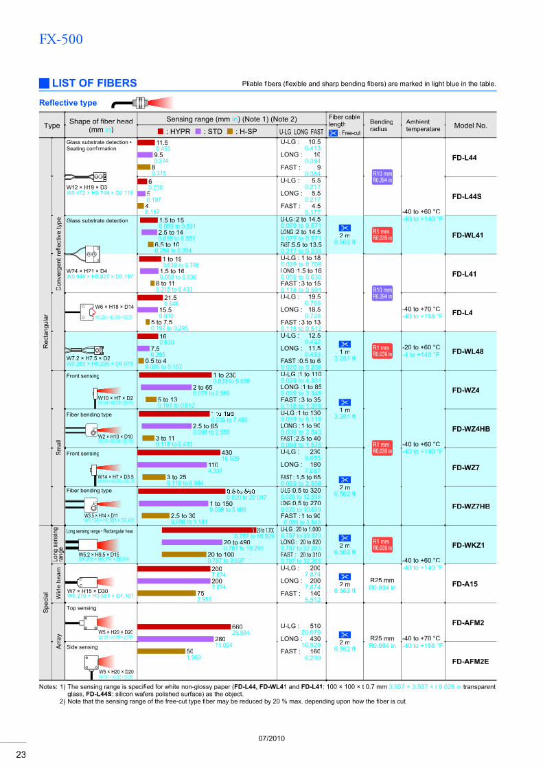
FX-500
23
Type Shape of fiber headfi(mm in)
Sensing range (mm in) (Note 1) (Note 2) Fiber cablelength
: Free-cut
Bendingradius
Ambienttemperatare Model No.
: HYPR : STD : H-SP U-LG LONG FAST
Rec
tang
ular
Con
verg
ent r
eflec
tive
type
fl
Glass substrate detection •Seating confi rmationfi
W12 × H19 × D3W0.472 × H0.748 × D0.118
11.50.453
9.50.374
80.315
U-LG : 10.50.413
LONG : 100.394
FAST : 90.354 R10 mmR10 mm
R0.394 inR0.394 in
FD-L44
60.23650.19740.157
U-LG : 5.50.217
LONG : 5.50.217
FAST : 4.50.177 -40 to +60 °C
-40 to +140 °F
FD-L44S
Glass substrate detection 1.5 to 150.059 to 0.5912.5 to 140.098 to 0.551
6.5 to 100.256 to 0.394
U-LG : 2 to 14.50.079 to 0.571LONG : 2 to 14.50.079 to 0.571FAST : 5.5 to 13.50.217 to 0.531
2 m6.562 ft
R1 mmR1 mmR0.039 inR0.039 in FD-WL41
W24 × H21 × D4W0.945 × H0.827 × D0.157
1 to 190.039 to 0.748
1.5 to 160.059 to 0.630
8 to 110.315 to 0.433
U-LG : 1 to 180.039 to 0.709LONG :1.5 to 160.059 to 0.630FAST : 3 to 150.118 to 0.591 R10 mmR10 mm
R0.394 inR0.394 in
FD-L41
W6 × H18 × D14
W0.236 × H0.709 × D0.551
21.50.846
15.50.610
5 to 7.50.197 to 0.295
U-LG : 19.50.768
LONG : 18.50.728
FAST : 3 to 130.118 to 0.512
-40 to +70 °C-40 to +158 °F FD-L4
W7.2 × H7.5 × D2W0.283 × H0.295 × D0.079
160.630
7.50.295
0.5 to 40.020 to 0.157
U-LG : 12.50.492
LONG : 11.50.453
FAST :0.5 to 60.020 to 0.236
1 m3.281 ft
R1 mmR1 mmR0.039 inR0.039 in
-20 to +60 °C-4 to +140 °F FD-WL48
Sm
all
Front sensing
W10 × H7 × D2W0.394 × H0.276 × D0.079
1 to 2300.039 to 9.055
2 to 650.079 to 2.559
5 to 130.197 to 0.512
U-LG :1 to 1100.039 to 4.331LONG : 1 to 850.039 to 3.346FAST : 3 to 350.118 to 1.378 1 m
3.281 ft
R1 mmR1 mmR0.039 inR0.039 in
-40 to +60 °C-40 to +140 °F
FD-WZ4
Fiber bending type
W2 × H10 × D10W0.079 × H0.394 × D0.394
0.039 to 7.4802.5 to 650.098 to 2.559
3 to 110.118 to 0.433
U-LG : 1 to 1300.039 to 5.118LONG : 1 to 900.039 to 3.543FAST : 2.5 to 400.098 to 1.575
FD-WZ4HB
Front sensing
W14 × H7 × D3.5W0.551 × H0.276 × D0.138
43016.929
1104.331
3 to 250.118 to 0.984
U-LG : 2309.055
LONG : 1807.087
FAST : 1.5 to 650.059 to 2.559 2 m
6.562 ft
FD-WZ7
Fiber bending type
W3.5 × H14 × D11W0.138 × H0.551 × D0.433
0.020 to 22.0471 to 1500.039 to 5.906
2.5 to 300.098 to 1.181
U-LG :0.5 to 3200.020 to 12.598LONG :0.5 to 2700.020 to 10.630FAST : 1 to 90
0.039 to 3.543
FD-WZ7HB
Spe
cial
Long
sen
sing
rang
e
Long sensing range • Rectangular head
W5.2 × H9.5 × D15W0.205 × H0.374 × D0.591
20 to 1,7000.787 to 66.929
20 to 4900.787 to 19.291
20 to 1000.787 to 3.937
U-LG : 20 to 1,0000.787 to 39.370LONG : 20 to 8200.787 to 32.283FAST : 20 to 3100.787 to 12.205
2 m6.562 ft
R1 mmR1 mmR0.039 inR0.039 in
-40 to +60 °C-40 to +140 °F
FD-WKZ1
Wid
e be
am
W7 × H15 × D30W0.276 × H0.591 × D1.181
2007.8742007.874
752.953
U-LG : 2007.874
LONG : 2007.874
FAST : 1405.512
2 m6.562 ft
R25 mmR0.984 in FD-A15
Arr
ay
Top sensing
W5 × H20 × D20W0.197 × H0.787 × D0.787
66025.984
28011.024
501.969
U-LG : 51020.079
LONG : 43016.929
FAST : 1606.299
2 m6.562 ft
R25 mmR0.984 in
-40 to +70 °C-40 to +158 °F
FD-AFM2
Side sensing
W5 × H20 × D20W0.197 × H0.787 × D0.787
FD-AFM2E
LIST OF FIBERS Pliable fi bers (fi flexible and sharp bending fl fibers) are marked in light blue in the table.fi
Refl ective type
Notes: 1) The sensing range is specifi ed for white non-glossy paper (fi FD-L44, FD-WL41 and FD-L41: 100 × 100 × t 0.7 mm 3.937 × 3.937 × t 0.028 in transparent glass, FD-L44S: silicon wafers polished surface) as the object.
2) Note that the sensing range of the free-cut type fi ber may be reduced by 20 % max. depending upon how thefi fi ber is cut.fi
07/2010
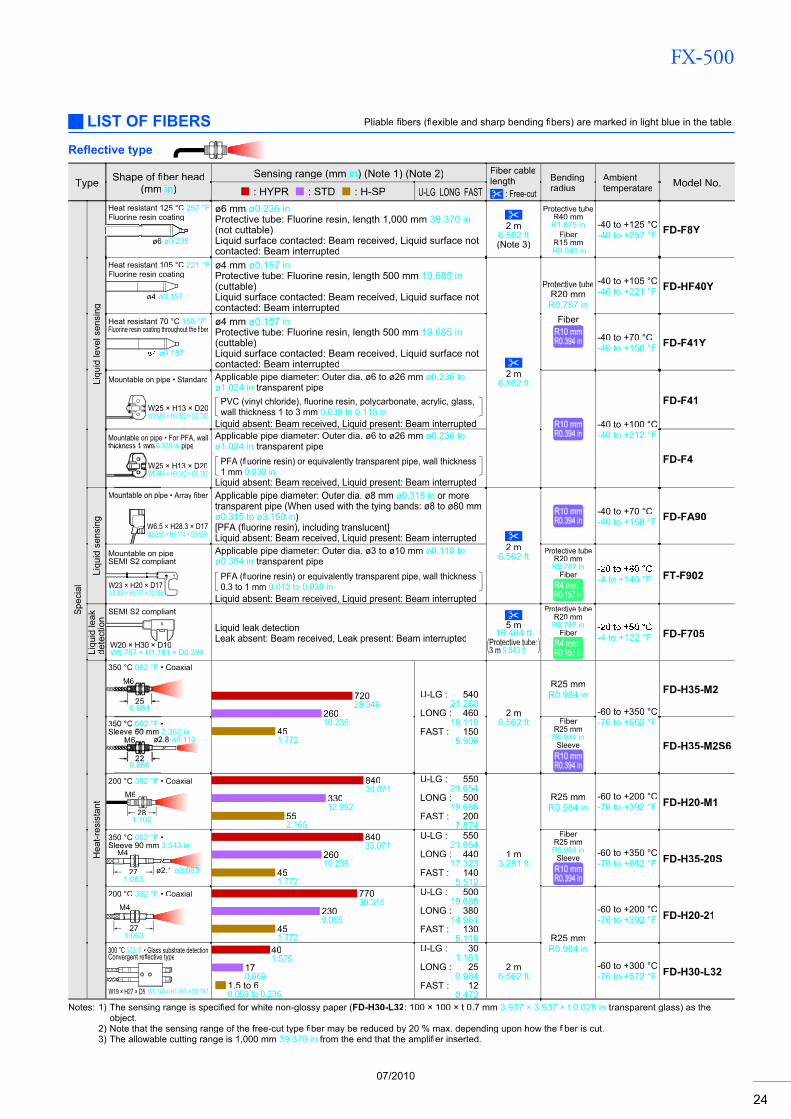
FX-500
24
Type Shape of fiber headfi(mm in)
Sensing range (mm in) (Note 1) (Note 2) Fiber cablelength
: Free-cut
Bendingradius
Ambienttemperatare Model No.
: HYPR : STD : H-SP U-LG LONG FAST
Spe
cial
Liqu
id le
vel s
ensi
ng
Heat resistant 125 °C 257 °FFluorine resin coating
ø6 ø0.236
ø6 mm ø0.236 inProtective tube: Fluorine resin, length 1,000 mm 39.370 in(not cuttable)Liquid surface contacted: Beam received, Liquid surface notcontacted: Beam interrupted
2 m6.562 ft(Note 3)
Protective tubeR40 mm R1.575 in
FiberR15 mmR0.591 in
-40 to +125 °C-40 to +257 °F FD-F8Y
Heat resistant 105 °C 221 °FFluorine resin coating
ø4 ø0.157
ø4 mm ø0.157 inProtective tube: Fluorine resin, length 500 mm 19.685 in(cuttable)Liquid surface contacted: Beam received, Liquid surface notcontacted: Beam interrupted
2 m6.562 ft
Protective tubeR20 mmR0.787 in
FiberR10 mmR10 mmR0.394 inR0.394 in
-40 to +105 °C-40 to +221 °F FD-HF40Y
Heat resistant 70 °C 158 °FFluorine resin coating throughout the fiberfi
ø0.157
ø4 mm ø0.157 inProtective tube: Fluorine resin, length 500 mm 19.685 in(cuttable)Liquid surface contacted: Beam received, Liquid surface notcontacted: Beam interrupted
-40 to +70 °C-40 to +158 °F FD-F41Y
Mountable on pipe • Standard
W25 × H13 × D20W0.984 × H0.512 × D0.787
Applicable pipe diameter: Outer dia. ø6 to ø26 mm ø0.236 to ø1.024 in transparent pipe
PVC (vinyl chloride), fluorine resin, polycarbonate, acrylic, glass, flwall thickness 1 to 3 mm 0.039 to 0.118 in
Liquid absent: Beam received, Liquid present: Beam interruptedq q p p R10 mmR10 mmR0.394 inR0.394 in
-40 to +100 °C-40 to +212 °F
FD-F41
Mountable on pipe • For PFA, wall thickness 1 mm 0.039 in pipe
5 × H13 × D2084 × H0.512 × D0.787
Applicable pipe diameter: Outer dia. ø6 to ø26 mm ø0.236 to ø1.024 in transparent pipe
PFA (fluorine resin) or equivalently transparent pipe, wall thicknessfl1 mm 0.039 in
Liquid absent: Beam received, Liquid present: Beam interruptedq q p p
FD-F4
Liqu
id s
ensi
ng
Mountable on pipe • Array fi berfi
W6.5 × H28.3 × D17W0.256 × H1.114 × D0.669
Applicable pipe diameter: Outer dia. ø8 mm ø0.315 in or moretransparent pipe (When used with the tying bands: ø8 to ø80 mm ø0.315 to ø3.150 in)[PFA (fluorine resin), including translucent]flLiquid absent: Beam received, Liquid present: Beam interrupted
2 m6.562 ft
R10 mmR10 mmR0.394 inR0.394 in
-40 to +70 °C-40 to +158 °F FD-FA90
Mountable on pipeSEMI S2 compliant
W23 × H20 × D17W0.906 × H0.787 × D0.669
Applicable pipe diameter: Outer dia. ø3 to ø10 mm ø0.118 to ø0.394 in transparent pipe
PFA (fluorine resin) or equivalently transparent pipe, wall thicknessfl0.3 to 1 mm 0.012 to 0.039 in
Liquid absent: Beam received, Liquid present: Beam interruptedq q p p
Protective tubeR20 mmR0.787 in
FiberR4 mmR4 mmR0.157 inR0.157 in
-4 to +140 °F FT-F902
Liqu
id le
akde
tect
ion
SEMI S2 compliant
W20 × H30 × D10W0.787 × H1.181 × D0.394
Liquid leak detectionLeak absent: Beam received, Leak present: Beam interrupted
5 m16.404 ft
Protective tube:3 m 9.843 ft
Protective tubeR20 mmR0.787 in
FiberR4 mmR4 mmR0.157 inR0.157 in
-4 to +122 °F FD-F705
Hea
t-res
ista
nt
350 °C 662 °F • Coaxial
M6
72028.346
26010.236
451.772
U-LG : 54021.260
LONG : 46018.110
FAST : 1505.906
2 m6.562 ft
R25 mmR0.984 in
-60 to +350 °C-76 to +662 °F
FD-H35-M2
35 •Sl 2.362 in
2.8 ø0.110
FiberR25 mmR0.984 in
SleeveR10 mmR10 mmR0.394 inR0.394 in
FD-H35-M2S6
200 °C 392 °F • Coaxial
M6
281.102
84033.071
33012.992
552.165
U-LG : 55021.654
LONG : 50019.685
FAST : 2007.874
1 m3.281 ft
R25 mmR0.984 in
-60 to +200 °C-76 to +392 °F FD-H20-M1
350 °C 662 °F •Sleeve 90 mm 3.543 in
M4
271.063
ø2.1 ø0.083
84033.071
26010.236
451.772
U-LG : 55021.654
LONG : 44017.323
FAST : 1405.512
FiberR25 mmR0.984 in
SleeveR10 mmR10 mmR0.394 inR0.394 in
-60 to +350 °C-76 to +662 °F FD-H35-20S
200 °C 392 °F • Coaxial
M4
271.063
77030.315
2309.055
451.772
U-LG : 50019.685
LONG : 38014.961
FAST : 1305.118 R25 mm
R0.984 in
-60 to +200 °C-76 to +392 °F FD-H20-21
300 °C 572 °F • Glass substrate detectionConvergent refl ective typefl
W19 × H27 × D5 W0.748 × H1.063 × D0.197
401.575
170.669
1.5 to 60.059 to 0.236
U-LG : 301.181
LONG : 250.984
FAST : 120.472
2 m6.562 ft
-60 to +300 °C-76 to +572 °F FD-H30-L32
LIST OF FIBERS Pliable fibers (fi flexible and sharp bending fl fibers) are marked in light blue in the table.fi
Refl ective type
Notes: 1) The sensing range is specifi ed for white non-glossy paper (fi FD-H30-L32: 100 × 100 × t 0.7 mm 3.937 × 3.937 × t 0.028 in transparent glass) as the object.
2) Note that the sensing range of the free-cut type fi ber may be reduced by 20 % max. depending upon how thefi fiber is cut.fi3) The allowable cutting range is 1,000 mm 39.370 in from the end that the amplifi er inserted.fi
07/2010
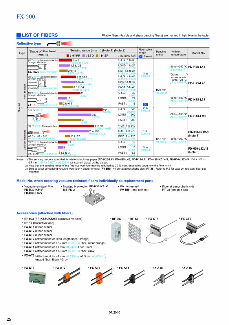
FX-500
25
Notes: 1) The sensing range is specifi ed for white non-glossy paper (fi FD-H25-L43, FD-H25-L45, FD-H18-L31, FD-H30-KZ1V-S, FD-H30-L32V-S: 100 × 100 × t0.7 mm 3.937 × 3.937 × t 0.028 in transparent glass) as the object.
2) Note that the sensing range of the free-cut type fi ber may be reduced by 20 % max. depending upon how thefi fi ber is cut.fi3) Sold as a set comprising vacuum type fi ber + photo-terminal (fi FV-BR1) + fiber at atmospheric side (fi FT-J8). Refer to P.6 for vacuum-resistant fi ber set fi
contents.
LIST OF FIBERS Pliable fi bers (fi flexible and sharp bending fl fibers) are marked in light blue in the table.fi
Refl ective type
Type Shape of fiber headfi(mm in)
Sensing range (mm in) (Note 1) (Note 2) Fiber cablelength
: Free-cut
Bendingradius
Ambienttemperatare Model No.
: HYPR : STD : H-SP U-LG LONG FAST
Spe
cial
Hea
t-res
ista
nt
250 °C 482 °F • Glass substrate detection Convergent refl ective typefl
W0.827 × H1.307 × D0.197
1 to 310.039 to 1.220
1.5 to 260.059 to 1.024
2 to 180.079 to 0.709
U-LG : 1 to 300.039 to 1.181LONG :1 to 280.039 to 1.102FAST : 1.5 to 240.059 to 0.945 3 m
9.843 ft
R25 mmR0.984 in
-20 to +250 °C-4 to +482 °F
Ordinarytemperature side:-20 to +70 °C-4 to +158 °F
FD-H25-L43
250 °C 482 °F • Glass substrate detection Convergent refl ective typefl
W21 × H34.5 × D5 W0.827 × H1.358 × D0.197
4 to 43.50.157 to 1.7135 to 420.197 to 1.654
6.5 to 340.256 to 1.339
U-LG : 4 to 430.157 to 1.693LONG :4.5 to 430.177 to 1.693FAST : 5 to 400.197 to 1.575
FD-H25-L45
180 °C 356 °F • Glass substrate detection Convergent refl ective typefl
W0.748 × H1.063 × D0.197
602.362
160.630
2 to 6.50.079 to 0.256
U-LG : 321.260
LONG : 240.945
FAST : 130.512 2 m
6.562 ft
-60 to +180 °C-76 to +356 °F FD-H18-L31
130 °C 266 °F
M6
210.827
88034.646
35013.780
652.559
U-LG : 64025.197
LONG : 60023.622
FAST : 2007.874
-60 to +130 °C-76 to +266 °F FD-H13-FM2
Vacu
um-re
sist
ant
300 °C 572 °F • Rectangular head
W9.5 × H5.2 × D15 W0.374 × H0.205 × D0.591
1 to 5000.039 to 19.685
2 to 2000.079 to 7.874
10 to 250.394 to 0.984
U-LG : 1 to 3400.039 to 13.386LONG : 1 to 2700.039 to 10.630FAST : 3 to 120
0.118 to 4.724
1 m3.281 ft
R18 mmR0.709 in
-30 to +300 °C-22 to +572 °F
FD-H30-KZ1V-S(Note 3)
300 °C 572 °F • Glass substrate detection Convergent refl ective typefl
W19 × H5 × D27 W0.748 × H0.197 × D1.063
180.709
80.315
1.5 to 30.059 to 0.118
U-LG : 120.472
LONG : 100.394
FAST : 5.50.217
3 m9.843 ft FD-H30-L32V-S
(Note 3)
FX-CT2•FX-CT1•RF-13•RF-003•
FX-AT2• FX-AT3• FX-AT4• FX• F•FX-CT3•
Model No. when ordering vacuum-resistant fi bers individually as replacement parts
FD-H30-KZ1VFD-H30-L32V
• Mouting bracket for Vacuum-resistant fi berfi FD-H30-KZ1VMS-FD-2Mouting bracket for FD-H30-KZ1V
FV-BR1 (one pair set)• Fiber at atmospheric sidePhoto-terminal
FT-J8 (one pair set)
Accessories (attached with fi bers)RF-003 (FR-KZ21//KZ21E exclusive refl ector)flRF-13 (Reflective tape)flFX-CT1 (Fiber cutter)FX-CT2 (Fiber cutter)FX-CT3 (Fiber cutter)FX-AT2 (Attachment for fi xed-length fi fi ber, Orange)fiFX-AT3 (Attachment for ø2.2 mm ø0.087 in fi ber, Clear orange)fiFX-AT4 (Attachment for ø1 mm ø0.039 in fi ber, Black)fiFX-AT5 (Attachment for ø1.3 mm ø0.051 in fi ber, Gray)fiFX-AT6 Attachment for ø1 mm ø0.039 in / ø1.3 mm ø0.051 in
mixed fiber, Black / Grayfi
••••••••••
07/2010
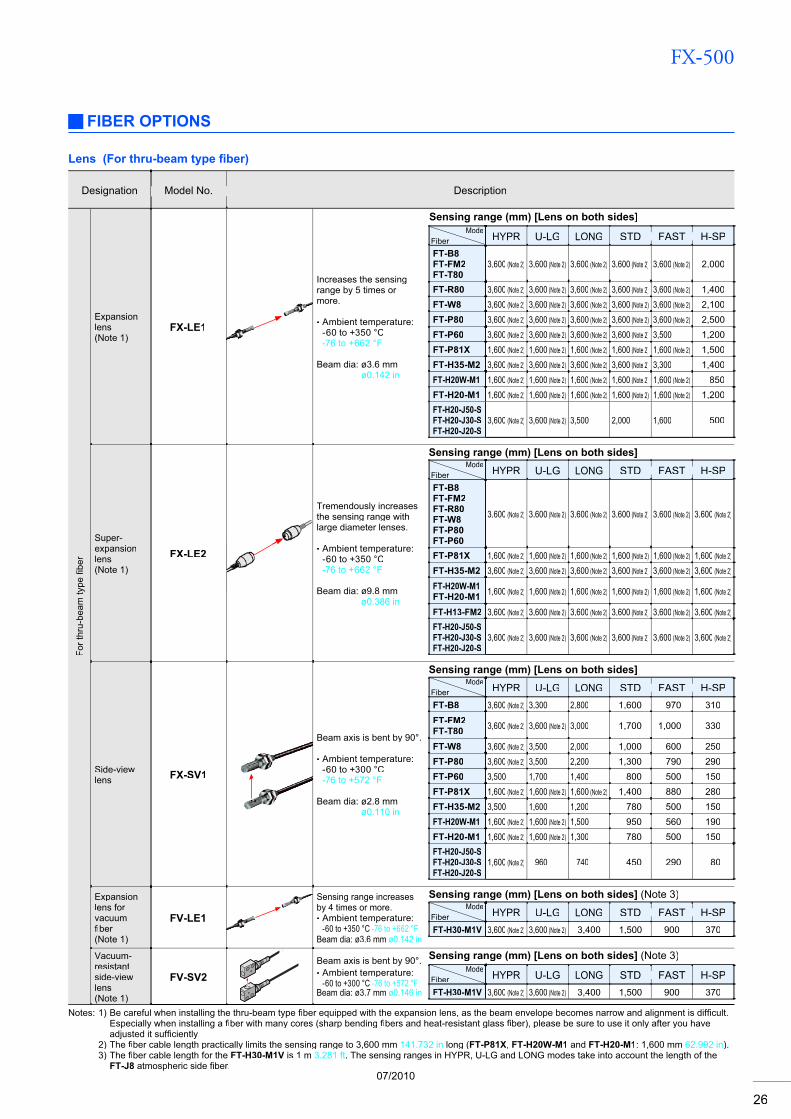
FX-500
26
FIBER OPTIONS
Lens (For thru-beam type fi ber)
Model No. DescriptionDesignation
For t
hru-
beam
type
fi ber
fi
Expansionlens(Note 1)
FX-LE1
Increases the sensingrange by 5 times or more.
Ambient temperature: -60 to +350 °C-76 to +662 °F
Beam dia: ø3.6 mmø0.142 in
•
Sensing range (mm) [Lens on both sides]Mode
Fiber HYPR U-LG LONG STD FAST H-SPFT-B8FT-FM2FT-T80
3,600 (Note 2) 3,600 (Note 2) 3,600 (Note 2) 3,600 (Note 2) 3,600 (Note 2) 2,000
FT-R80 3,600 (Note 2) 3,600 (Note 2) 3,600 (Note 2) 3,600 (Note 2) 3,600 (Note 2) 1,400FT-W8 3,600 (Note 2) 3,600 (Note 2) 3,600 (Note 2) 3,600 (Note 2) 3,600 (Note 2) 2,100FT-P80 3,600 (Note 2) 3,600 (Note 2) 3,600 (Note 2) 3,600 (Note 2) 3,600 (Note 2) 2,500FT-P60 3,600 (Note 2) 3,600 (Note 2) 3,600 (Note 2) 3,600 (Note 2) 3,500 1,200FT-P81X 1,600 (Note 2) 1,600 (Note 2) 1,600 (Note 2) 1,600 (Note 2) 1,600 (Note 2) 1,500FT-H35-M2 3,600 (Note 2) 3,600 (Note 2) 3,600 (Note 2) 3,600 (Note 2) 3,300 1,400FT-H20W-M1 1,600 (Note 2) 1,600 (Note 2) 1,600 (Note 2) 1,600 (Note 2) 1,600 (Note 2) 850FT-H20-M1 1,600 (Note 2) 1,600 (Note 2) 1,600 (Note 2) 1,600 (Note 2) 1,600 (Note 2) 1,200FT-H20-J50-SFT-H20-J30-SFT-H20-J20-S
3,600 (Note 2) 3,600 (Note 2) 3,500 2,000 1,600 500
Super-expansionlens(Note 1)
FX-LE2
Tremendously increasesthe sensing range withlarge diameter lenses.
Ambient temperature: -60 to +350 °C-76 to +662 °F
Beam dia: ø9.8 mmø0.386 in
•
Sensing range (mm) [Lens on both sides]Mode
Fiber HYPR U-LG LONG STD FAST H-SPFT-B8FT-FM2FT-R80FT-W8FT-P80FT-P60
3,600 (Note 2) 3,600 (Note 2) 3,600 (Note 2) 3,600 (Note 2) 3,600 (Note 2) 3,600 (Note 2)
FT-P81X 1,600 (Note 2) 1,600 (Note 2) 1,600 (Note 2) 1,600 (Note 2) 1,600 (Note 2) 1,600 (Note 2)
FT-H35-M2 3,600 (Note 2) 3,600 (Note 2) 3,600 (Note 2) 3,600 (Note 2) 3,600 (Note 2) 3,600 (Note 2)
FT-H20W-M1FT-H20-M1 1,600 (Note 2) 1,600 (Note 2) 1,600 (Note 2) 1,600 (Note 2) 1,600 (Note 2) 1,600 (Note 2)
FT-H13-FM2 3,600 (Note 2) 3,600 (Note 2) 3,600 (Note 2) 3,600 (Note 2) 3,600 (Note 2) 3,600 (Note 2)
FT-H20-J50-SFT-H20-J30-SFT-H20-J20-S
3,600 (Note 2) 3,600 (Note 2) 3,600 (Note 2) 3,600 (Note 2) 3,600 (Note 2) 3,600 (Note 2)
Side-viewlens FX-SV1
Beam axis is bent by 90°.
Ambient temperature: -60 to +300 °C-76 to +572 °F
Beam dia: ø2.8 mmø0.110 in
•
Sensing range (mm) [Lens on both sides]Mode
Fiber HYPR U-LG LONG STD FAST H-SPFT-B8 3,600 (Note 2) 3,300 2,800 1,600 970 310FT-FM2FT-T80 3,600 (Note 2) 3,600 (Note 2) 3,000 1,700 1,000 330
FT-W8 3,600 (Note 2) 3,500 2,000 1,000 600 250FT-P80 3,600 (Note 2) 3,500 2,200 1,300 790 290FT-P60 3,500 1,700 1,400 800 500 150FT-P81X 1,600 (Note 2) 1,600 (Note 2) 1,600 (Note 2) 1,400 880 280FT-H35-M2 3,500 1,600 1,200 780 500 150FT-H20W-M1 1,600 (Note 2) 1,600 (Note 2) 1,500 950 560 190FT-H20-M1 1,600 (Note 2) 1,600 (Note 2) 1,300 780 500 150FT-H20-J50-SFT-H20-J30-SFT-H20-J20-S
1,600 (Note 2) 960 740 450 290 80
Expansionlens for vacuumfi berfi(Note 1)
FV-LE1
Sensing range increasesby 4 times or more.
Ambient temperature: -60 to +350 °C -76 to +662 °F
Beam dia: ø3.6 mm ø0.142 in
•
Sensing range (mm) [Lens on both sides] (Note 3)Mode
Fiber HYPR U-LG LONG STD FAST H-SPFT-H30-M1V 3,600 (Note 2) 3,600 (Note 2) 3,400 1,500 900 370
Vacuum-resistantside-viewlens(Note 1)
FV-SV2Beam axis is bent by 90°.
Ambient temperature: -60 to +300 °C -76 to +572 °F
Beam dia: ø3.7 mm ø0.146 in
•
Sensing range (mm) [Lens on both sides] (Note 3)Mode
Fiber HYPR U-LG LONG STD FAST H-SPFT-H30-M1V 3,600 (Note 2) 3,600 (Note 2) 3,400 1,500 900 370
Notes: 1) Be careful when installing the thru-beam type fiber equipped with the expansion lens, as the beam envelope becomes narrow and alignment is diffi fiff cult. fiEspecially when installing a fiber with many cores (sharp bendingfi fibers and heat-resistant glassfi fiber), please be sure to use it only after you have fiadjusted it suffiff ciently.fi
2) The fiber cable length practically limits the sensing range to 3,600 mm fi 141.732 in long (FT-P81X, FT-H20W-M1 and FT-H20-M1: 1,600 mm 62.992 in).3) The fiber cable length for thefi FT-H30-M1V is 1 m 3.281 ft. The sensing ranges in HYPR, U-LG and LONG modes take into account the length of the
FT-J8 atmospheric side fi ber.fi07/2010
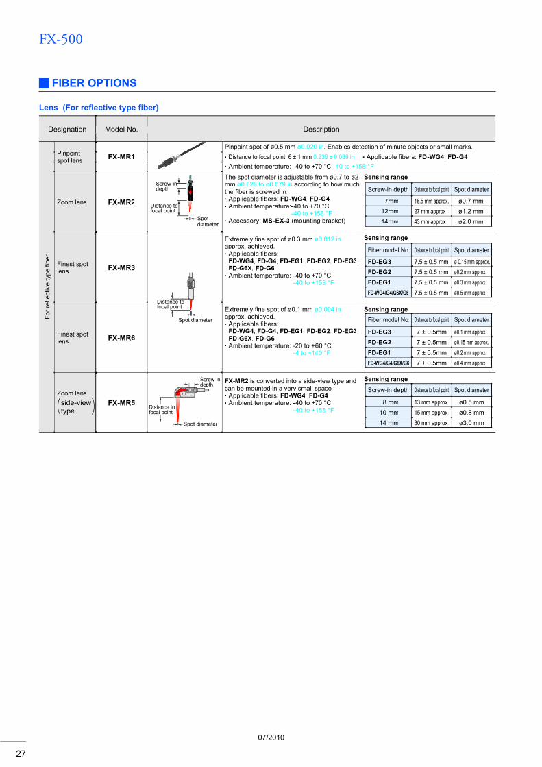
FX-500
27
Lens (For refl ective type fi ber)
Model No. DescriptionDesignation
For r
efl e
ctiv
e ty
pe
flfi b
erfi
Pinpointspot lens FX-MR1
Pinpoint spot of ø0.5 mm ø0.020 in. Enables detection of minute objects or small marks.Distance to focal point: 6 ± 1 mm 0.236 ± 0.039 in• Applicable fibers: fi FD-WG4, FD-G4•
Ambient temperature: -40 to +70 °C -40 to +158 °F•
Zoom lens FX-MR2
Screw-indepth
Distance tofocal point
Spotdiameter
The spot diameter is adjustable from ø0.7 to ø2 mm ø0.028 to ø0.079 in according to how much the fi ber is screwed in.fi
Applicable fibers: fi FD-WG4, FD-G4Ambient temperature:-40 to +70 °C
-40 to +158 °FAccessory: MS-EX-3 (mounting bracket)
••
•
Sensing range
Screw-in depth Distance to focal point Spot diameter
7mm 18.5 mm approx. ø0.7 mm12mm 27 mm approx. ø1.2 mm14mm 43 mm approx. ø2.0 mm
Finest spotlens FX-MR3
Spot diameter
Distance tofocal point
Extremely fine spot of ø0.3 mm fi ø0.012 inapprox. achieved.
Applicable fi bers: fiFD-WG4, FD-G4, FD-EG1, FD-EG2, FD-EG3,FD-G6X, FD-G6Ambient temperature: -40 to +70 °C
-40 to +158 °F
•
•
Sensing range
Fiber model No. Distance to focal point Spot diameter
FD-EG3 7.5 ± 0.5 mm ø 0.15 mm approx.FD-EG2 7.5 ± 0.5 mm ø0.2 mm approx.FD-EG1 7.5 ± 0.5 mm ø0.3 mm approx.FD-WG4/G4/G6X/G6 7.5 ± 0.5 mm ø0.5 mm approx.
Finest spotlens FX-MR6
Extremely fine spot of ø0.1 mm fi ø0.004 inapprox. achieved.
Applicable fi bers: fiFD-WG4, FD-G4, FD-EG1, FD-EG2, FD-EG3,FD-G6X, FD-G6Ambient temperature: -20 to +60 °C
-4 to +140 °F
•
•
Sensing rangeFiber model No. Distance to focal point Spot diameter
FD-EG3 7 ± 0.5mm ø0.1 mm approx.FD-EG2 7 ± 0.5mm ø0.15 mm approx.FD-EG1 7 ± 0.5mm ø0.2 mm approx.FD-WG4/G4/G6X/G6 7 ± 0.5mm ø0.4 mm approx.
Zoom lensside-viewtype
FX-MR5
Screw-indepth
Spot diameter
Distance totancfocal pointal p
FX-MR2 is converted into a side-view type andcan be mounted in a very small space.
Applicable fi bers:fi FD-WG4, FD-G4Ambient temperature: -40 to +70 °C
-40 to +158 °F
••
Sensing rangeScrew-in depth Distance to focal point Spot diameter
8 mm 13 mm approx. ø0.5 mm10 mm 15 mm approx. ø0.8 mm14 mm 30 mm approx. ø3.0 mm
FIBER OPTIONS
07/2010
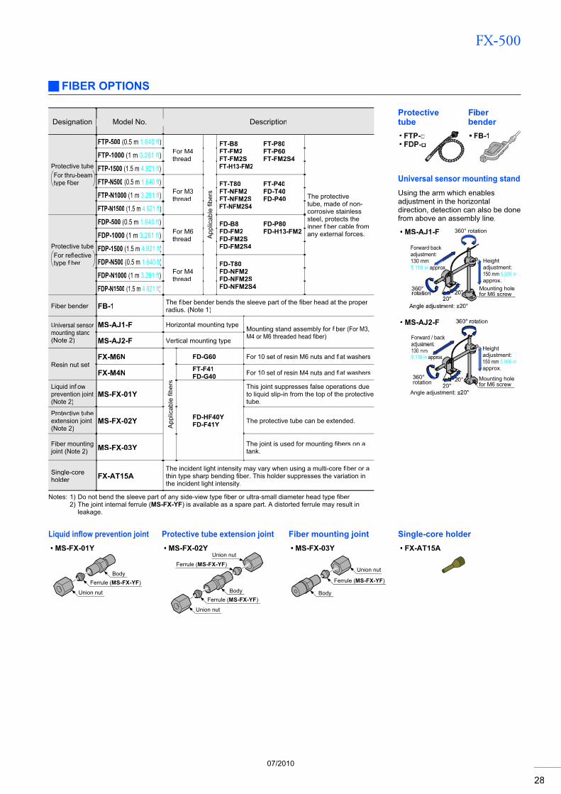
FX-500
28
FIBER OPTIONS
Protectivetube
FTP-FD
••
Fiberbender
FB-1
FX-AT15A•
Single-core holderLiquid infl ow prevention jointMS-FX-01Y•
Protective tube extension jointMS-FX-02Y•
Fiber mounting jointMS-FX-03Y•
Union nut
BodyFerrule (MS-FX-YF)
Union nut
Union nut
Body
Ferrule (MS-FX-YF)
Ferrule (MS-FX-YF)
Union nut
Body
Ferrule (MS-FX-YF)
Model No. DescriptionDesignation
Protective tubeFor thru-beam type fi berfi
FTP-500 (0.5 m 1.640 ft)For M4thread
App
licab
lefi b
ers
fi
FT-B8FT-FM2FT-FM2SFT-H13-FM2
FT-P80FT-P60FT-FM2S4
The protectivetube, made of non-corrosive stainless steel, protects theinner fiber cable from fiany external forces.
FTP-1000 (1 m 3.281 ft)
FTP-1500 (1.5 m 4.921 ft)
FTP-N500 (0.5 m 1.640 ft)For M3thread
FT-T80FT-NFM2FT-NFM2SFT-NFM2S4
FT-P40FD-T40FD-P40FTP-N1000 (1 m 3.281 ft)
FTP-N1500 (1.5 m 4.921 ft)
Protective tubeFor refl ectivefltype fi berfi
FDP-500 (0.5 m 1.640 ft)For M6thread
FD-B8FD-FM2FD-FM2SFD-FM2S4
FD-P80FD-H13-FM2FDP-1000 (1 m 3.281 ft)
FDP-1500 (1.5 m 4.921 ft)
FDP-N500 (0.5 m 1.640 ft)For M4thread
FD-T80FD-NFM2FD-NFM2SFD-NFM2S4
FDP-N1000 (1 m 3.281 ft)
FDP-N1500 (1.5 m 4.921 ft)
Fiber bender FB-1 The fi ber bender bends the sleeve part of thefi fiber head at the proper firadius. (Note 1)
Universal sensor mounting stand(Note 2)
MS-AJ1-F Horizontal mounting type Mounting stand assembly for fi ber fi (For M3,M4 or M6 threaded head fiber)fiMS-AJ2-F Vertical mounting type
Resin nut setFX-M6N
App
licab
lefib
ers
fi
FD-G60 For 10 set of resin M6 nuts and fl at washersfl
FX-M4N FT-F41FD-G40 For 10 set of resin M4 nuts and fl at washersfl
Liquid infl ow flprevention joint (Note 2)
MS-FX-01Y
FD-HF40YFD-F41Y
This joint suppresses false operations dueto liquid slip-in from the top of the protective tube.
Protective tubeextension joint(Note 2)
MS-FX-02Y The protective tube can be extended.
Fiber mounting joint (Note 2) MS-FX-03Y The joint is used for mounting fibers on a fi
tank.
Single-coreholder FX-AT15A
The incident light intensity may vary when using a multi-core fi ber or a fithin type sharp bending fi ber. This holder suppresses the variation infithe incident light intensity.
Notes: 1) Do not bend the sleeve part of any side-view type fi ber or ultra-small diameter head type fi fiber.fi2) The joint internal ferrule (MS-FX-YF) is available as a spare part. A distorted ferrule may result in
leakage.
Universal sensor mounting standUsing the arm which enablesadjustment in the horizontaldirection, detection can also be donefrom above an assembly line.
MS-AJ1-F•
MS-AJ2-F•
360° rotation
360°rotation
Angle adjustment: ±20°20°
20°
Heightadjustment:150 mm 5.906 inapprox.
Mounting holefor M6 screw
Forward·backadjustment:130 mm5.118 in approx.
360° rotation
360°rotation
Angle adjustment: ±20°20°
20° Mounting holefor M6 screw
Forward / backadjustment:130 mm5.118 in approx.
Heightadjustment:150 mm 5.906 inapprox.
07/2010
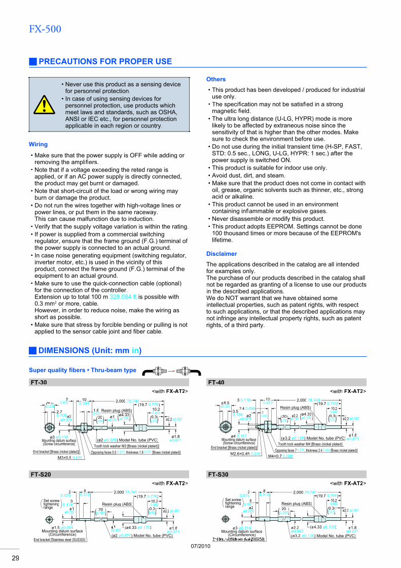
FX-500
29
Others
This product has been developed / produced for industrialuse only.The specifi cation may not be satisfi fied in a strong fimagnetic fi eld.fiThe ultra long distance (U-LG, HYPR) mode is more likely to be affected by extraneous noise since the sensitivity of that is higher than the other modes. Make sure to check the environment before use.Do not use during the initial transient time (H-SP, FAST, STD: 0.5 sec., LONG, U-LG, HYPR: 1 sec.) after the power supply is switched ON.This product is suitable for indoor use only.Avoid dust, dirt, and steam.Make sure that the product does not come in contact with oil, grease, organic solvents such as thinner, etc., strong acid or alkaline.This product cannot be used in an environment containing inflammable or explosive gases.flNever disassemble or modify this product.This product adopts EEPROM. Settings cannot be done 100 thousand times or more because of the EEPROM's lifetime.
•
•
•
•
•••
•
••
DIMENSIONS (Unit: mm in)
Super quality fi bers • Thru-beam type
FT-30<with FX-AT2>
FT-40<with FX-AT2>
FT-S20<with FX-AT2>
FT-S30<with FX-AT2>
(19.7 0.776)ø0.256
ø2ø0.079
ø1ø0.039
(ø2 ø0.079) Model No. tube (PVC)
ø2.2 ø0.087
Resin plug (ABS)
ø3 ø0.118Mounting datum surface(Screw circumference)
gg
End bracket [Brass (nickel plated)][ ( p )] Opposing faces 5.5 pp g 0.217, thickness 1.8 0.071 [Brass (nickel plated)][ ( p )]Tooth lock washer M3 [Brass (nickel plated)]
ø1.8ø0.071
10.20.402(ø4.33)ø0.170((2020))0.787(( )) (0.3)0.012((
20.079
10100.394394 2,000 78.740
1.80.0712.7
0.106
M3×0.5 0.020
ø2ø0.079
ø4 0.157Mounting datum surface(Screw circumference)
gg ((ø3.2 ø0.126)) Model No. tube (PVC)( )
End bracket [Brass (nickel plated)][ ( p )]M2.6×0.45 0.018 M4×0.7 0.028
Opposing faces 7pp g 0.276, thickness 2.4 0.094 [Brass (nickel plated)][ ( p )]Tooth lock washer M4 [Brass (nickel plated)]
ø1.8ø0.071
Resin plug (ABS) 10.200.402
(19.7(19 0.776)3 0.118 1212
0.472472 2,000 78.740
2.4 0.09410.039
ø8.5ø0.335
3.50.138 ((2020))0.787(( )) (0.3)0.012(( ø2.2 ø0.087
ø2.2ø0.087 (ø4.33))ø0.170
1ø0.039
End bracket [Stainless steel (SUS303)][ ( )](ø2 ø0.079) Model No. tube (PVC)
ø2.2 ø0.087
ø1.8ø0.071
(ø4.33 ø0.170)
ø1ø0.039
ø1.5 ø0.059Mounting datum surface
(Circumference)gg
Resin plug (ABS)3
0.11810.20.402
(19.7 0.776)2
0.0792,000 78.74088
0.31531Set screw tighteningrange (0.3)0.012((( 20 )0.787
[ ( )]((ø3.2 ø0.126)) Model No. tube (PVC)( )
ø2.2 ø0.087
ø1.8(ø4.33 ø0.170)
ø2ø0.079
ø3 ø0.118Mounting datum surface
(Circumference)gg
Resin plug (ABS)10.2
(19.7( 0.776)2,000 78.74088
0.315315
0.197Set screw tighteningrange
ø0.071
( 20 )0.787
ø2.2ø0.087
(0.3)0.012((0.402
20.079
Never use this product as a sensing devicefor personnel protection.In case of using sensing devices for personnel protection, use products whichmeet laws and standards, such as OSHA,ANSI or IEC etc., for personnel protectionapplicable in each region or country.
•
•
Wiring
Make sure that the power supply is OFF while adding or removing the amplifi ers.fiNote that if a voltage exceeding the reted range isapplied, or if an AC power supply is directly connected,the product may get burnt or damaged.Note that short-circuit of the load or wrong wiring mayburn or damage the product.Do not run the wires together with high-voltage lines or power lines, or put them in the same raceway.This can cause malfunction due to induction.Verify that the supply voltage variation is within the rating.If power is supplied from a commercial switchingregulator, ensure that the frame ground (F.G.) terminal of the power supply is connected to an actual ground.In case noise generating equipment (switching regulator,inverter motor, etc.) is used in the vicinity of thisproduct, connect the frame ground (F.G.) terminal of theequipment to an actual ground.Make sure to use the quick-connection cable (optional)for the connection of the controller.Extension up to total 100 m 328.084 ft is possible with 0.3 mm2 or more, cable.However, in order to reduce noise, make the wiring asshort as possible.Make sure that stress by forcible bending or pulling is notapplied to the sensor cable joint and fi ber cable.fi
•
•
•
•
••
•
•
•
PRECAUTIONS FOR PROPER USE
Disclaimer
The applications described in the catalog are all intended for examples only. The purchase of our products described in the catalog shall not be regarded as granting of a license to use our productsin the described applications. We do NOT warrant that we have obtained some intellectual properties, such as patent rights, with respect to such applications, or that the described applications may not infringe any intellectual property rights, such as patent rights, of a third party.
07/2010
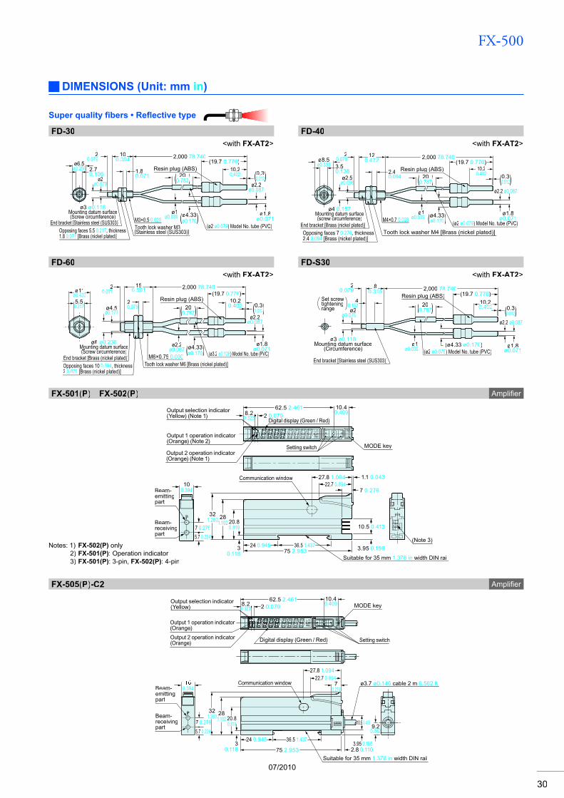
FX-500
30
Super quality fi bers • Refl ective type
FD-30<with FX-AT2>
FD-40<with FX-AT2>
FD-60<with FX-AT2>
FD-S30<with FX-AT2>
(19.7 0.776)
ø1ø0.039
ø3 ø0.118Mounting datum surface(Screw circumference)
gg
(ø2 ø0.079) Model No. tube (PVC)End bracket [Stainless steel (SUS303)][ ( )] M3×0.5 0.020
Opposing faces 5.5 0.217, thickness1.8 0.071 [Brass (nickel plated)]
Tooth lock washer M3[Stainless steel (SUS303)]
ø2.2ø0.087
Resin plug (ABS)
20.079
ø6.5ø0.256 2.7
0.106
ø1.8ø0.071
( 2020 )0.7870 787 (0.3)0.012((10.20.4020 402
2,000 78.740
(ø4.33)ø0.170
ø2ø0.079
10100.394394
1.80.071
ø1ø0.039
ø2.5ø0.098
ø4 0.157Mounting datum surface(screw circumference)
gg
3.50.138 Resin plug (ABS)
(19.7 0.776)2,000 78.740
(ø2( ø0.079) Model No. tube (PVC)End bracket [Brass (nickel plated)][ ( p )]M4×0.7 0.028
Opposing faces 7 0.276, thickness 2.4 0.094 [Brass (nickel plated)]
Tooth lock washer M4 [Brass (nickel plated)]
ø2.2 ø0.087
ø1.8ø0.071(ø4.33)ø0.170
( 20 )0.787
12120.472472ø8.5
ø0.335
20.079
2.40.094
10.20.4020 402 (0.3)0.012((
ø0.177ø4.5
ø2.2ø0.087
øø1111ø0.433ø0 4335.50.217
Resin plug (ABS)(19.7 0.776)
20.079
15150.59159 2,000 78.740
20.079
ø6 ø0.236Mounting datum surface(Screw circumference)
gg(ø3.2 ø0.126) Model No. tube (PVC)
End bracket [Brass (nickel plated)][ ( p )] M6×0.75 0.030Opposing faces 10 0.394, thickness2 0.079 [Brass (nickel plated)]
Tooth lock washer M6 [Brass (nickel plated)]
(0.3)0.012((10.20.402( 20 )0.787
ø2.2ø0.087 (ø4.33))ø0.170
ø1.8ø0.071
ø2ø0.079ø
Resin plug (ABS) (19.7 0.776)2
0.079 2,000 78.740
ø3 ø0.118Mounting datum surface
(Circumference)gg
End bracket [Stainless steel (SUS303)][ ( )](ø2 ø0.079) Model No. tube (PVC)
ø2.2 ø0.087
ø1.8ø0.071
40.157
Set screwtighteningrange
880.31550 31
( 20 )0.787 (0.3)0.012((10 210.20.4020 402
(ø4.33 ø0.170)ø1ø0.039
DIMENSIONS (Unit: mm in)
Amplifi erFX-501(P) FX-502(P)
Notes: 1) FX-502(P) only2) FX-501(P): Operation indicator3) FX-501(P): 3-pin, FX-502(P): 4-pin
24 0.945 36.5 1.437 3.95 0.156
10.5 0.413
27.8 1.094
7 0.276
30.118
281.102
321.260 20.8
0.8195.7 0.224
Communication window
Suitable for 35 mm 1.378 in width DIN rail
100.394
75 2.953
1.1 0.043
Setting switch
Output 1 operation indicator (Orange) (Note 2)
Digital display (Green / Red)
62.5 2.461
MODE key
Output selection indicator (Yellow) (Note 1)
Output 2 operation indicator (Orange) (Note 1)
8.20.323 2 0.079
22.7 0.894
(Note 3)
Beam-receivingpart
Beam-emittingpart
7 0.276
10.40.409
Amplifi erFX-505(P)-C2
3.95 0.156
9.20.362
2.8 0.110
62.5 2.461
Output 1 operation indicator(Orange)Output 2 operation indicator (Orange) Digital display (Green / Red) Setting switch
MODE keyOutput selection indicator (Yellow)
Communication window
Suitable for 35 mm 1.378 in width DIN rail
ø3.7 ø0.146 cable 2 m 6.562 ft
2 0.079
22.7 0.894
0.394
8.20.323
10.40.409
Beam-receivingpart
Beam-emittingpart
5.7 0.2247 0.276
281.102
321.260 20.8
0.819
30.118 75 2.953
27.8 1.094
70.276
24 0.945 36.5 1.437
10.5 0.413
07/2010
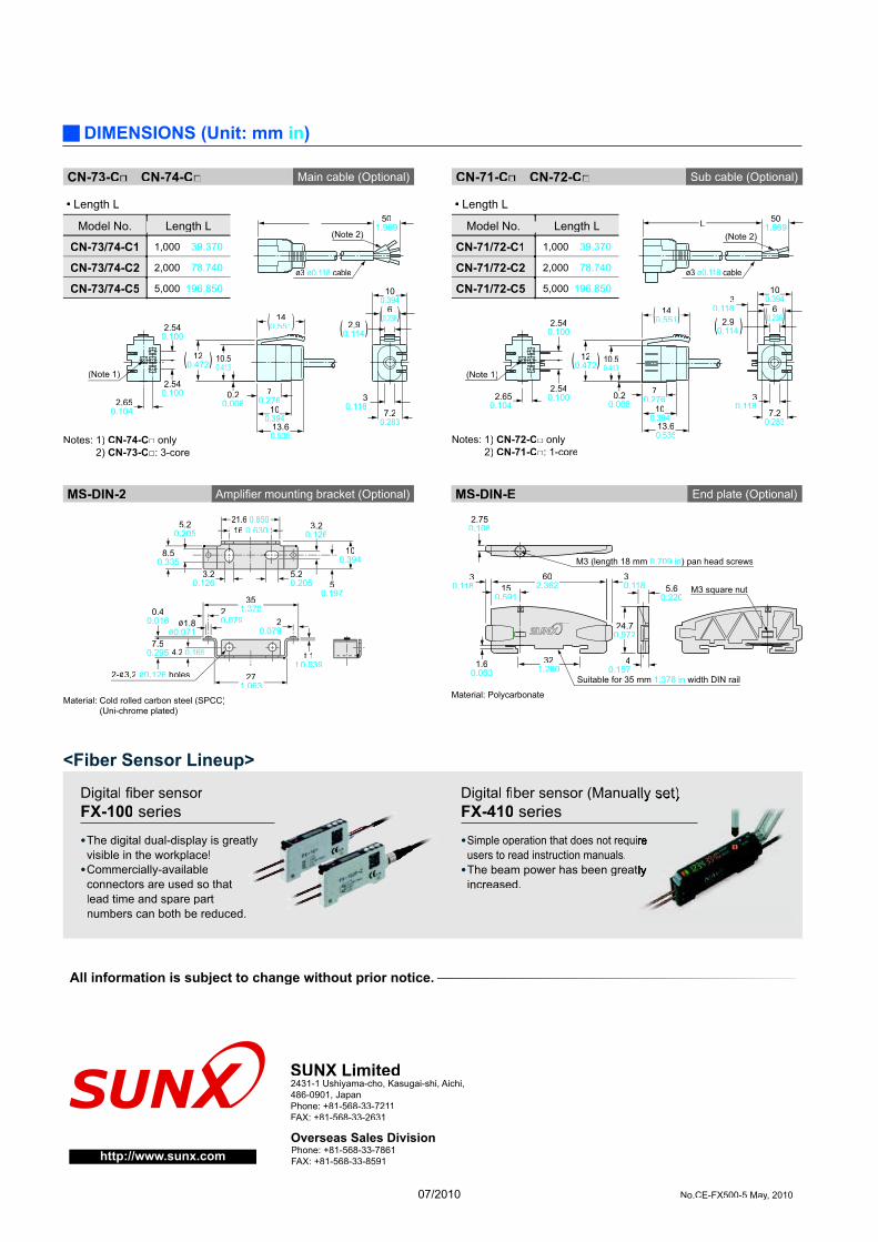
DIMENSIONS (Unit: mm in)
Main cable (Optional)CN-73-C CN-74-C Sub cable (Optional)CN-71-C CN-72-C
ø3 ø0.118 cable
501.969
(Note 1)
2.650.104
2.540.100
2.540.100
10.50.0.41341
0.20.008
13.60.535
100.394
14140.5510 551
7.20.283
30.118
2.90.114
60.236
100.394
70.276
12120.472( )
( ) ( )( )
(Note 2)
Length L•
Model No. Length L
CN-73/74-C1 1,000 39.370
CN-73/74-C2 2,000 78.740
CN-73/74-C5 5,000 196.850
L
2.650.104
2.540.100
2.540.100
10.50.0.41341
0.20.008
13.60.535
100.394
14140.5510 551
7.20.283
30.118
2.90.114
60.236
100.394
ø3 ø0.118 cable
70.276
501.969
12120.472( )
( ) ( )
(Note 2)
(Note 1))
30.118
( )
Model No. Length L
CN-71/72-C1 1,000 39.370
CN-71/72-C2 2,000 78.740
CN-71/72-C5 5,000 196.850
Length L•
Notes: 1) CN-74-C only2) CN-73-C : 3-core
Amplifi er mounting bracket (Optional)MS-DIN-2
2-ø3.2 ø0.126 holes
20.079
t 1t 0.039
0.40.016
7.50.295 4.2 0.165
20.079ø1.8
ø0.071
35351.3781 378
27271.0631 063
3.20.126
5.20.205
8.50.335
5.20.205
3.20.126
50.197
21.621.6 0.8500.850166 0.6300 630
10000.394339
Material: Cold rolled carbon steel (SPCC)(Uni-chrome plated)
Notes: 1) CN-72-C only2) CN-71-C : 1-core
End plate (Optional)MS-DIN-E
2.750.108
40.157
30.118
M3 (length 18 mm 0.709 in) pan head screws
M3 square nut5.60.220
24.70.972
1.60.063
321.260
602.36215
0.591
30.118
Suitable for 35 mm 1.378 in width DIN rail
Material: Polycarbonate
No.CE-FX500-5 May, 2010
2431-1 Ushiyama-cho, Kasugai-shi, Aichi,486-0901, JapanPhone: +81-568-33-7211FAX: +81-568-33-2631
SUNX Limited
Phone: +81-568-33-7861 FAX: +81-568-33-8591
Overseas Sales Division http://www.sunx.com
All information is subject to change without prior notice.
<Fiber Sensor Lineup>
Digital fi ber sensorfiFX-100 series
Digital fiber sensor (Manually set)fiFX-410 series
The digital dual-display is greatlyvisible in the workplace!
Simple operation that does not requiusers to read instruction manuals.The beam power has been greatincreased.
Commercially-availableconnectors are used so that lead time and spare part numbers can both be reduced.
07/2010