Embed Size (px)
Citation preview
Atari Floppy Disk Copy Protection
By Jean Louis-Guérin (DrCoolZic) Revision 1.2 – June 2014
Atari Floppy Disk Copy Protection
Copyleft Jean Louis-Guérin (DrCoolZic) – Rev 1.2 - June 2014 Page 2 / 64
Table of Contents Table of Contents ................................................................................................................ 2
Chapter 1. Presentation ................................................................................................... 4
Chapter 2. Copy Protection Summary Table .................................................................. 6
Chapter 3. Copy Protection Detail Description .............................................................. 7 3.1 Protections based on Layout ................................................................................................ 7 3.1.1 Number of Tracks (NOT).......................................................................................................... 8 3.1.2 Shifted Tracks (SHT) ................................................................................................................ 9 3.1.3 Track Layout Pattern (TLP) .................................................................................................... 11 3.1.4 Number Of Sectors (NOS) ..................................................................................................... 12 3.1.5 Sector Sizes (SSZ) ................................................................................................................. 13 3.1.6 Invalid ID Field (IIF) ................................................................................................................ 13 3.1.7 Duplicate Sector Number (DSN) ............................................................................................ 15 3.1.8 Sector Within Sector (SWS) ................................................................................................... 16 3.1.9 Non Standard DAM (NSD) ..................................................................................................... 16 3.1.10 Sector with No Data (SND) .................................................................................................... 17 3.1.11 Invalid Data CRC Sector (IDC) .............................................................................................. 17 3.1.12 No Sector Data Track (NST) .................................................................................................. 17 3.1.13 Hidden Data into GAP (HDG) ................................................................................................ 18 3.1.14 Invalid Data in Gap (IDG) ....................................................................................................... 18 3.1.15 Sync Mark in Data (SMD) ...................................................................................................... 18 3.1.16 Invalid Sync-mark Sequence (ISS) ........................................................................................ 19 3.1.17 Partially unformatted track (PUT) ........................................................................................... 19 3.2 Protections based on Fuzzy Bits ........................................................................................ 20 3.2.1 Fuzzy Sector (FZS) ................................................................................................................ 20 3.2.2 Fuzzy Track (FZT) .................................................................................................................. 23 3.2.3 No Flux Area (NFA) ................................................................................................................ 23 3.3 Protections based on Bit-rate Variation ............................................................................ 24 3.3.1 Long / Short Sector (LGS & SHS) .......................................................................................... 24 3.3.2 Long/Short Track (LGT & SHT) ............................................................................................. 25 3.3.3 Intra-Sector Bit-rate Variation (IBV) ....................................................................................... 25 3.4 Protections based on Track Alteration .............................................................................. 26 3.4.1 Physical Alteration of Track ................................................................................................... 26
Chapter 4. Atari Low-Level Formats ..............................................................................27 4.1 “Standard” 9-10-11 Sectors of 512 Bytes Format ............................................................. 28 4.2 “Standard” 128-256-512-1024 Bytes / Sector Format ....................................................... 29
Chapter 5. Useful Information ........................................................................................30 5.1 WD1772 DPLL Input Circuitry ............................................................................................. 30 5.2 WD1772 Detection of Border Bits ....................................................................................... 31 5.3 No Flux Area on Disk ........................................................................................................... 32 5.3.1 Checking NFA with the WD1772 ........................................................................................... 32 5.4 Unformatted Diskette / Track / Sector ................................................................................ 34 5.4.1 Presentation ........................................................................................................................... 34 5.4.2 Partially unformatted track ..................................................................................................... 35 5.4.3 Partially formatted Track ........................................................................................................ 37 5.4.4 Unformatted track detection ................................................................................................... 37 5.4.5 How to reproduce unformatted areas on Floppy Disks? ........................................................ 37
Chapter 6. Analysis of Games/Programs .......................................................................39 6.1 Dungeon Master (FTL Inc.) .................................................................................................. 40 6.2 D50 Editor (DrT) .................................................................................................................... 42 6.3 Populous (Electronic Arts) .................................................................................................. 44 6.4 Theme Park Mystery (Image Works) .................................................................................. 46 6.5 Computer Hits Volume 2 (Beau-Jolly) ................................................................................ 48 6.6 Kick Off 2 .............................................................................................................................. 51 6.7 Night Shift ............................................................................................................................. 53
Atari Floppy Disk Copy Protection
Copyleft Jean Louis-Guérin (DrCoolZic) – Rev 1.2 - June 2014 Page 3 / 64
6.8 Barbarian .............................................................................................................................. 56 6.9 Colorado ............................................................................................................................... 57 6.10 Turrican ................................................................................................................................. 58 6.11 Operation Neptune ............................................................................................................... 60
Chapter 7. Terminology used in this document ............................................................61
Chapter 8. References .....................................................................................................62 8.1 Documents / Articles ........................................................................................................... 62 8.2 Forums Threads ................................................................................................................... 62 8.3 Related Patents .................................................................................................................... 63 8.4 Web Sites .............................................................................................................................. 63 8.5 FDC & Related Information ................................................................................................. 63
Chapter 9. Document history ..........................................................................................64
Atari Floppy Disk Copy Protection
Copyleft Jean Louis-Guérin (DrCoolZic) – Rev 1.2 - June 2014 Page 4 / 64
Chapter 1. Presentation This document describes floppy disk protection mechanisms used on the Atari platform. This type of copy protection is very old and, with many years of development and the usage of sophisticated floppy disk hardware, has conducted to numerous protection methods frequently referred as key disk protection. The key disk protection method has at least two obvious qualities: first, a key disk can be simultaneously used as protection and distribution disk and second, this type of protection is very cheap but nevertheless hard to tamper with. So, key disks have been widely used for protection of Atari programs/games. In order to understand the key disk based protection, one is assumed to have some basic knowledge about FD/FDC data and operation.
Some of the FD protection mechanisms are generic to many platforms while some are directly related to a specific Floppy Disk Controller used on a specific platform. Therefore, in order to get a general understanding, I have reviewed the FD protections mechanism used on several platforms: Amiga, Commodore C64, PC, Tandy, Atari 8 bits and Atari ST 16 bits (see the references section).
A lot of information about the different copy protection mechanisms presented here has been collected from the Web. Links to the original information / Web sites can be found at the end of this document in the references section.
In order to validate this document, I have analyzed the protections of many original floppy disks. For that matter I have developed several programs over time: For detailed analysis of timing information, the first program that I have created is called
Analyze. It runs on Atari and PC. This program reads files produced on an Atari by the Discovery Cartridge and performs a detailed analysis of the flux reversals read from a diskette. This program takes its root in experiments I have done back in the 80s! The program is in maintenance mode and is replaced by the AUFIT program presented below.
For basic protection analysis I have created a program running on Atari called Panzer (Protection ANalyZER) that automatically detects and reports most of the protections. This program also provides the capability to analyze and report detailed sectors and tracks information (including track and sector timing). For more information please refer to the Panzer documentation.
KFAnalyze program reads input Stream files generated by the KryoFlux board. As a Stream file provides Atari FD information at the flux reversals level (more information in the references section), it is possible to provide much more accurate detections of protections especially those related to bit cell timing variation. The heart of this program is a Western Digital WD1772 Floppy Disk Controller emulation. This emulation (that implements a full DPLL data separator) provides functions equivalent to the read track, read address, and read sector commands directly from the flux read from the Stream files. Therefore it is possible to process the Stream information as if we were read by an Atari WD1772 FDC but with a lot of extra information especially on timing. For more information please read the KFAnalyze documentation.
KFPanzer (KryoFlux Protection ANalyZER) is a program running on PC that analyzes the protection using information from Stream files produced by a KryoFlux board. It is a combination of the Panzer and KFAnalyze programs. For more information please read the KFPanzer documentation.
My latest program is called AUFIT (Atari Universal FD Image Tools). It combines the features of the above programs with a nice Graphical User Interface. This programs can read information at different levels (down to flux transition level), analyzes and displays information about the protections, and can write images for emulation. For more information please read the AUFIT documentation.
Atari Floppy Disk Copy Protection
Copyleft Jean Louis-Guérin (DrCoolZic) – Rev 1.2 - June 2014 Page 5 / 64
Information about protection mechanisms presented in this document should help in the creation of techniques/programs for duplication, preservation, and emulation of original Atari diskettes with the following philosophy:
A preservation technique should always do the most to ensure the integrity of the resultant
copy. The copy produced should operate just like the original and not remove any protection, or modify the program being copied in any way. The preservation technique must do the up
most to check that the copy produced is identical to the original.
Many Floppy Disks using protections presented here can be duplicated without the usage of special HW (special copy programs have been designed to do that), but more advanced protections require using specially designed HW. This can be vintage HW like the Discovery Cartridge or the recently released KryoFlux board and SuperCard Pro devices. Analog copiers, like the Blitz cable and associated software, can sometime create a working copy of a protected diskette but they do not fulfill the above requirements of producing a copy identical to the original.
Preservation has different meanings for different people but can be classified into two broad categories: A “real preservation” is intended to save all the required information from a floppy disk so
that it is possible to emulate the original FD but more importantly it is also possible to physically duplicate the original FD. A good example is the IPF format from SPS project.
An “emulation preservation” is meant to save enough information from a floppy disk so that it is possible to emulate the behavior of the original FD in an emulator (could be a software or hardware emulator). A good example is the STX format from the Pasti project.
It is interesting to note than most emulation / duplication programs do not care about (and sometimes can’t detect) the detailed underlying protection mechanisms used. These programs store enough information to replicate the effect of a specific protection. For example this kind of program will detect the presence of fuzzy bytes but it will not care if they are produced by bits in Ambiguous areas, or bits rate violation. As a matter of fact finding the exact underlying causes often requires specific hardware like a Discovery Cartridge.
I have added, for each of the protection mechanism presented in this document, a sub-section (called Emulation) that describes a possible way (usually what is used in Pasti STX format) of “preserving” the necessary information to be able to emulate the protection correctly. In most cases you need to store some or all of the following information for each tracks to preserve: The track layout and content The content of all the sectors (even fake ones), Timing information for sector, track, and sometimes group of bytes Fuzzy bytes information.
I want to thanks to many people on Atari forum for taking time to discuss some of the protections presented here.
Atari Floppy Disk Copy Protection
Copyleft Jean Louis-Guérin (DrCoolZic) – Rev 1.2 - June 2014 Page 6 / 64
Chapter 2. Copy Protection Summary Table The following table summarizes the copy protections described in this document: Number of Tracks (NOT) Extra Tracks (NOT-EXT) Unformatted Tracks (NOT-UFT)
Shifted Tracks (SHT) Data Field Over Index-pulse (SHT-DOI) Data Field Beyond Index-pulse (SHT-DBI) ID Field over Index pulse (SHT-IOI)
Track Layout Pattern (TLP) Number Of Sectors (NOS) Sector Sizes (SSZ) Invalid ID Field (IIF) Non Standard IDAM (IIF-NSI) Invalid Sector Track (IIF-IST) Invalid Sector Head (IIF-ISH) Invalid Sector Number (IIF-ISN) Invalid Sector Length (IIF-ISL) Invalid ID CRC (IIF-IIC)
Duplicate Sector Number (DSN) Sector Within Sector (SWS) Non Standard DAM (NSD) Sector with No Data (SND) Invalid Data CRC Sector (IDC) No Sector Data Track (NST) Hidden Data into GAP (HDG) Invalid Data in Gap (IDG) Sync Mark in Data (SMD) Invalid Sync-mark Sequence (ISS) Partially unformatted track (PUT) Fuzzy Sector (FZS) Fuzzy Track (FZT) No Flux Area (NFA) Long / Short Sector (LGS & SHS) Long/Short Track (LGT & SHT) Intra-Sector Bit-rate Variation (IBV)
Note that several protections’ mechanisms can be combined and that some protection always implies other protection (e.g. fuzzy bit always results in CRC error).
Atari Floppy Disk Copy Protection
Copyleft Jean Louis-Guérin (DrCoolZic) – Rev 1.2 - June 2014 Page 7 / 64
Chapter 3. Copy Protection Detail Description In this section I provide a detailed description of the different protection’s mechanisms used in Atari Key disks. The protections have been grouped into four categories: Protections based on Layout Protections based on Fuzzy Bits/Bytes Protections based on Bit-rate Variation Protections based on Alteration
3.1 Protections based on Layout This category contains protections based on modification of track(s) and/or sector(s) layout compared to a “standard track” of a “normal diskette”.
A “standard track” on an Atari is composed of 9 sectors each with 512 bytes of data sequentially numbered from sector 1 until sector 9.
A “normal diskette” has one or two sides (i.e. single or double sided) each having 80 tracks numbered from 0 to 79. A more detailed description of formats can be found in the Atari double density floppy diskette section.
However it is not uncommon to use diskettes with up to 11 sectors and more than 80 tracks as it allows packing more data. A good duplication/imaging program should be able to detect and reproduce all these alternatives and therefore they are not really considered as protection. However special care should be taken for diskettes with 11 sectors / track as the track timings are in this case extremely tight.
But beyond these basic variations of the layout we also find in this category some protections that are difficult to detect (so that a copy program would not easily find them) and some that cannot be reproduced without special hardware.
Atari Floppy Disk Copy Protection
Copyleft Jean Louis-Guérin (DrCoolZic) – Rev 1.2 - June 2014 Page 8 / 64
3.1.1 Number of Tracks (NOT)
A “normal Atari diskette” has 80 tracks numbered 0 through 79 on each side. Some protections are based on adding extra tracks, or having unformatted tracks.
3.1.1.1 Extra Tracks (NOT-EXT) Description: It is possible to write up to 82 or even 83 tracks on one side of a diskette. It
is also possible to “hide” one or several tracks on the second side of an “officially” (as specified in the boot sector) single sided diskette.
Creation: It is quite easy to create extra track by sending appropriate information to the FDC. Note that some early Atari drives cannot position the head past track 79 and beware that using tracks over 82 has been reported to damage some floppy drives.
Detection: You have to probe the diskette using FDC commands to check if some extra tracks exist on one side (probing 82 tracks is usually sufficient). For Single Sided diskette, you also need to probe for hidden track on second side.
Duplication: Easy by software. Emulation: Just need to store information for the extra tracks. Example: Passengers on the Wind (Infogrames) uses tracks 80 & 81.
3.1.1.2 Unformatted Tracks (NOT-UFT) Description: A “normal Atari diskette” has 80 tracks numbered 0 through 79 on each side.
It is possible that not all of these tracks are formatted. For detail description of unformatted track please refer to Unformatted Diskette / Track / Sector.
Creation: On a non-preformatted diskette you only format the tracks that need to be formatted! On a preformatted diskette you need to mimic unformatted tracks by writing, for example, some random data to those tracks?
Detection: A seek command with the verify option should fail on unformatted track. Alternatively you can perform a read-track and look for pseudo random data and a read address should return zero sector found. Note that it is also possible to hide data in an “officially” unformatted track.
Duplication: If only the presence of an invalid track is tested then it is easy to reproduce by software. Placing hidden data in what looks like an unformatted track is usually difficult to detect.
Emulation: The preservation file needs to flag missing tracks (e.g. indicating 0 sector). Examples: Barbarian (Track 74 – 79 missing), Run the Gauntlet (Ocean Software), Kick
Off 2
Atari Floppy Disk Copy Protection
Copyleft Jean Louis-Guérin (DrCoolZic) – Rev 1.2 - June 2014 Page 9 / 64
3.1.2 Shifted Tracks (SHT)
Normally the first sector of a track starts after just after the index and the last sector of the track end-up before the next index pulse. The pre-index GAP (at beginning of a track) is about 60 bytes. The post-index preamble GAP (at the end of a track) is about 600 bytes. In this condition the track write splice (location where the floppy drive write gate is tuned on/off) is located very close to the index. Many protections shift the position of the track relative to the index and this results in also shifting the write splice. The shifted track protections can be further sub-classified as explained thereafter but usually this is not important for an emulation file or for a duplication devices.
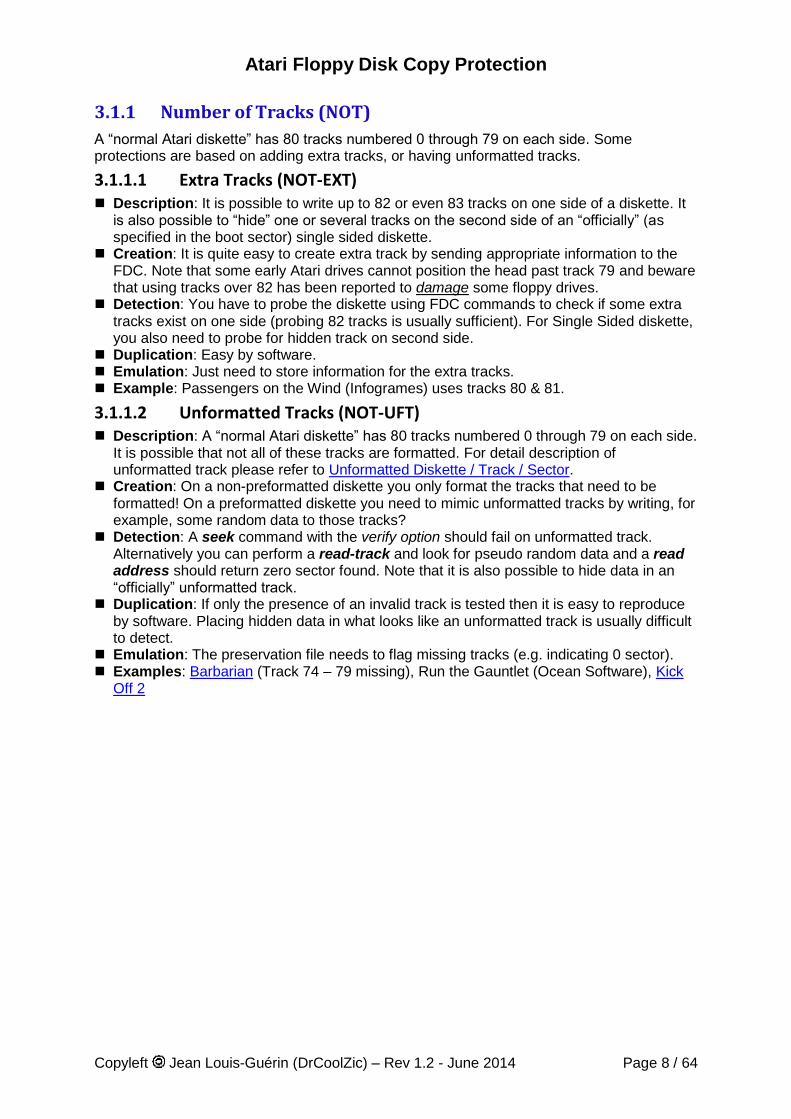
3.1.2.1 Data Field Over Index-pulse (SHT-DOI) Description: A sector where the Data Field span “over the index”. Normally all sectors of
a track should end up before the index pulse. Yet it is possible to create a track with a total length that is slightly more than what a normal track can hold. This results in the last sector “wrapping around” the beginning of the track. As there is a small area at the beginning of a track (the post-index GAP), which is not used for storing data, it is possible to overwrite partially this section of the track.
Sector 1
G2 ID G3bG3a DATA G4
Sector 2
G2 ID G3bG3a DATA G4 G5G1 G2 ID G3bG3a DATA G4 G2 ID G3bG3a DATA G4G5 G1
Sector n
Sector positions relative to the index pulse for a normal track
Sector 1
G2 ID G3bG3a DATA G4
Sector 2
G2 ID G3bG3a DATA G4 G5G1 G2 ID G3bG3a DATA G4 G2 ID G3bG3a DATA G4G5 G1
Sector n
Sector positions relative to the index pulse for a track with Data Over Index
Creation: As mentioned above it is possible to create a “long track” with a total length that is slightly more than what a normal track can hold (usually about 10 to 20 bytes). This result in the header of the last track sector to be placed close to the end of the track. The write-track command of the WD1772 FDC starts with the leading edge of the index pulse and continues until the next index pulse. Therefore the last sector of a “long track” will be truncated during the format operation. However the write-sector command on this truncated sector will execute normally and this will result in data being written over and beyond the index pulse. However usually this protection is done using special hardware. In that case it is possible to write a track shifted by a large amount.
Detection: The last sector spread over the index pulse but it is read normally by the read-sector command. It is therefore necessary to use a read-track command to find out that the last sector actually wrap over the beginning of the track.
Duplication: Data Field passing over IAM can cause significant problems for copier unaware of their existence. Dumb copy will not result in correct sector position and therefore this protection has been used extensively used on Atari. However once detected the duplication of such sector can be done by formatting correctly the track.
Emulation: Requires storing the track information in the preservation file. Example: Kick Off 2 places almost all the data of one sector at the beginning of a track.
Atari Floppy Disk Copy Protection
Copyleft Jean Louis-Guérin (DrCoolZic) – Rev 1.2 - June 2014 Page 10 / 64
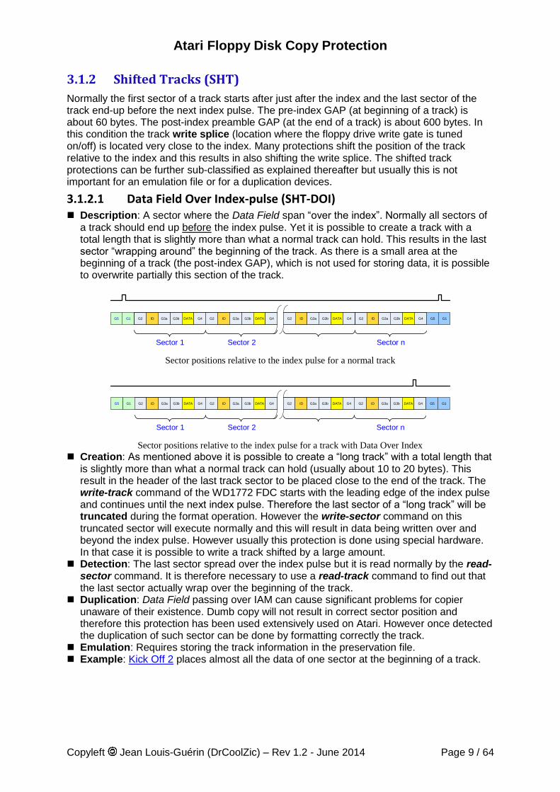
3.1.2.2 Data Field Beyond Index-pulse (SHT-DBI) Description: This is an extreme variation of the Data Over Index protection. Normally all
sectors of a track should end up before the index pulse but it is possible to create a track where the ID Field for the last sector is placed at the very end of the track with the corresponding Data Field placed at the very beginning of the track. You have to remember that the Data Address Mark of the Data Field is to be found within 43 bytes from the last ID Field CRC byte and therefore placement of the ID Field and corresponding Data Field in the track is needs to be very accurate. The last sector “wraps around” the beginning of the track. See Computer Hits Volume 2 for an example.
Sector 1
G2 ID G3bG3a DATA G4
Sector 2
G2 ID G3bG3a DATA G4 G5G1 G2 ID G3bG3a DATA G4 G2 ID G3bG3a DATA G4G5 G1
Sector n
Sector positions relative to the index pulse for a normal track
Sector 1
G2 ID G3bG3a DATA G4
Sector 2
G2 ID G3bG3a DATA G4G1 G2 ID G3bG3a DATA G4 G2 ID G3bG3a DATA G4 G1
Sector n
Sector positions relative to the index pulse for a track with Data Field beyond index
Creation: This is done by creating a special layout for the track: the track needs to start with a Data Field (very close to beginning of track) then followed by a set of nine or ten ID Field and Data Field and terminated by an ID Field very close to the end of the track.
Detection: The last sector has the ID Field before the index pulse and the Data Field after the index pulse but it is read normally by the read-sector command. It is therefore necessary to use the read-track command to find out that the last sector actually spread over the beginning of the track.
Important note: The DMA can only transmit multiple of 16 bytes from the FDC. Therefore
during a read-track command, one or several of the last bytes (always less than 16) may not be transferred by the DMA. Consequently it is possible that a read-track does not transmit
the ID Field (or transmits it partially) when it is placed at the very end of a track. However the FDC read-address and read-sector commands will find this ID field for this sector correctly.
Duplication: Sector passing over IAM can cause significant problems for copier unaware of their existence. Dumb copy will not result in correct sector position. It is almost impossible to reliably place an ID field at the very end of the track by software due to floppy drives rotation speed variation. Therefore this protection requires specific hardware.
Emulation: Requires to store the track information, but as the last address field might not be read correctly it also requires to store all the sector IDs and their positions.
Example: Computer Hits Volume 2 (Beau-Jolly)
Atari Floppy Disk Copy Protection
Copyleft Jean Louis-Guérin (DrCoolZic) – Rev 1.2 - June 2014 Page 11 / 64
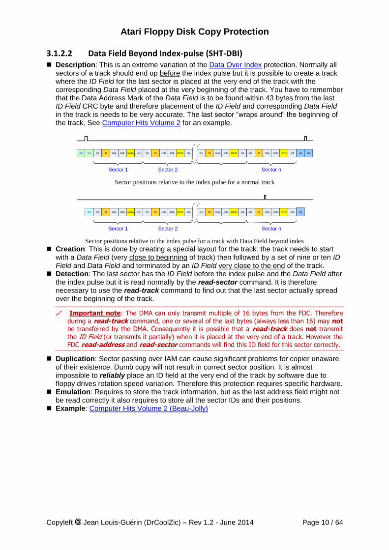
3.1.2.3 ID Field over Index pulse (SHT-IOI) Description: A sector where the ID Field span “over the index”. This is a variation of the
Data Filed Over the Index-pulse protection. But in that case the ID which is positioned just above the index. Please refer to the Data Field Over Index-pulse protection for details.
Creation: It is not possible to place the ID over the index using the standard WD1772 FDC. Therefore this protection requires to use special HW device.
Detection: It is usually not possible to read this ID using a read track command because the ID segment is at the very end of the track and the data read usually get stuck in the DMA buffer (see above). Even though this ID can’t be seen using a read track it can be read using read address and read sector commands.
Duplication: To position correctly the ID Field it is necessary to use special HW. Emulation: Need to store the result of read track and read sector command. Example: Colorado, Computer Hits Volume 2 disk 2.
The last three protections are also somewhat challenging for Hardware copier. The copy should not be done from index to index as this will results in a track splice in middle of the data over the index. The copy should start from the first sector until the last sector using the correct shifted starting position with respect to the index.
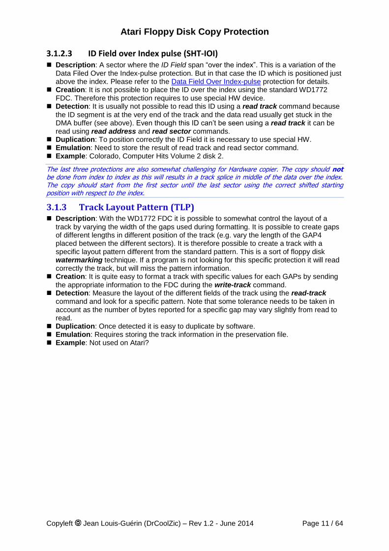
3.1.3 Track Layout Pattern (TLP) Description: With the WD1772 FDC it is possible to somewhat control the layout of a
track by varying the width of the gaps used during formatting. It is possible to create gaps of different lengths in different position of the track (e.g. vary the length of the GAP4 placed between the different sectors). It is therefore possible to create a track with a specific layout pattern different from the standard pattern. This is a sort of floppy disk watermarking technique. If a program is not looking for this specific protection it will read correctly the track, but will miss the pattern information.
Creation: It is quite easy to format a track with specific values for each GAPs by sending the appropriate information to the FDC during the write-track command.
Detection: Measure the layout of the different fields of the track using the read-track command and look for a specific pattern. Note that some tolerance needs to be taken in account as the number of bytes reported for a specific gap may vary slightly from read to read.
Duplication: Once detected it is easy to duplicate by software. Emulation: Requires storing the track information in the preservation file. Example: Not used on Atari?
Atari Floppy Disk Copy Protection
Copyleft Jean Louis-Guérin (DrCoolZic) – Rev 1.2 - June 2014 Page 12 / 64
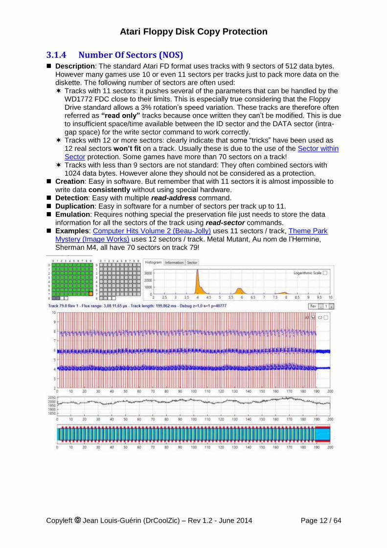
3.1.4 Number Of Sectors (NOS) Description: The standard Atari FD format uses tracks with 9 sectors of 512 data bytes.
However many games use 10 or even 11 sectors per tracks just to pack more data on the diskette. The following number of sectors are often used: Tracks with 11 sectors: it pushes several of the parameters that can be handled by the
WD1772 FDC close to their limits. This is especially true considering that the Floppy Drive standard allows a 3% rotation’s speed variation. These tracks are therefore often referred as “read only” tracks because once written they can’t be modified. This is due to insufficient space/time available between the ID sector and the DATA sector (intra-gap space) for the write sector command to work correctly.
Tracks with 12 or more sectors: clearly indicate that some “tricks” have been used as 12 real sectors won’t fit on a track. Usually these is due to the use of the Sector within Sector protection. Some games have more than 70 sectors on a track!
Tracks with less than 9 sectors are not standard: They often combined sectors with 1024 data bytes. However alone they should not be considered as a protection.
Creation: Easy in software. But remember that with 11 sectors it is almost impossible to write data consistently without using special hardware.
Detection: Easy with multiple read-address command. Duplication: Easy in software for a number of sectors per track up to 11. Emulation: Requires nothing special the preservation file just needs to store the data
information for all the sectors of the track using read-sector commands. Examples: Computer Hits Volume 2 (Beau-Jolly) uses 11 sectors / track, Theme Park
Mystery (Image Works) uses 12 sectors / track. Metal Mutant, Au nom de l’Hermine, Sherman M4, all have 70 sectors on track 79!
Atari Floppy Disk Copy Protection
Copyleft Jean Louis-Guérin (DrCoolZic) – Rev 1.2 - June 2014 Page 13 / 64
3.1.5 Sector Sizes (SSZ) Description: Normally the tracks have sectors with 512 bytes long Data Field. But it is
possible to create a track with different data field size (usually a mixture of 512 and 1024)1. This is a more reliable approach to increase the overall capacity of a track rather than using 11 sectors of 512 bytes. Non-standard sector size are not be considered as a protection. Two common examples of format used are: 9 sectors of 512 bytes plus 1 sector with 1024 bytes, and 5 sectors of 1024 bytes plus 1 sector with 512 bytes.
Creation: Easy in software. Detection: Easy with multiple read-address command. Duplication: Easy in software. Emulation: Requires nothing special the preservation file just needs to store the data
information for all the sectors of the track using read-sector commands. Examples: Kick Off 2, Turrican uses tracks with a mixture of 1024 and 512 bytes sectors.
3.1.6 Invalid ID Field (IIF)
An ID Field contains the following information after the ID Address Mark: a Track Number, a Side/Head Number, a Sector Number, a Sector Length, and two CRC bytes. During a read-sector command when an ID Field is located on the disk, the WD1772 compares the Track Number of the ID Field with its internal Track Register. If there is not a match, the next encountered ID Field is read and a comparison is made again. If there is a match, the Sector Number of the ID Field is compared with its internal Sector Register. If there is no Sector match, the next encountered ID Field is read off the disk and a comparison is made again. If the ID Field CRC is correct, the Data Field is located and an internal register is loaded with the Sector Length. It is possible to have sector with invalid values in the ID field as described below.
3.1.6.1 Non Standard IDAM (IIF-NSI) Description: The normal IDAM (ID Address Mark) used by the WD1772 is the character
$FE which is sent after a sync sequence of 3 $A1 sync marks. An undocumented feature of the WD1772 is to accept the character $FF as an IDAM2.
Creation: During a write-track command it is possible to use $FF instead of the normal $FE IDAM character.
Detection: As the read-address command and the read-sector command execute normally it is easy to hide the fact that a non-standard IDAM has been used. Detection can either be done through a read-track command or with the read-address command. In both cases you have to look for an $FF character instead of $FE in the ID field. Note that the ID Field reads with no CRC error.
Duplication: Once detected this protection is easy to duplicate. Emulation: Requires storing the complete track information in the preservation file. Example: Not sure it is used on Atari
1 Note that several of the BIOS calls will not work for sectors with size different than 512.
2 Note that, in MFM, for the marks characters between $F8 and $FF the least significant bit is always ignored by the FDC and therefore : $F8 = $F9, …, $FE = $FF
Atari Floppy Disk Copy Protection
Copyleft Jean Louis-Guérin (DrCoolZic) – Rev 1.2 - June 2014 Page 14 / 64
3.1.6.2 Invalid Sector Track (IIF-IST) Description: A track that has one or several sectors with ID Fields that contains a track
number different from the actual track number. In order for the type I commands (e.g. seek) to succeed, on such a track, the verify bit has to be reset. Otherwise the FDC check that at least one sector has the correct track number. The read-sector command using “standard” parameters will also fail.
Creation: Using a write-track command with incorrect track number in one or several ID Field.
Detection: The read-sector command compares the track number of the ID Field with the track register if this matches it then compares the sector number of the ID Field with the sector register. If any compare operation fails the FDC retry 5 times then terminate the command with a record not found (RNF) error. Reading this kind of sector is possible but requires playing with the FDC registers (i.e. loading the track register with the invalid track value).
Duplication: Easy by software Emulation: The preservation file should store the exact ID block. Example: Virus TODO game with all ID fields wrong
3.1.6.3 Invalid Sector Head (IIF-ISH) Description: An ID field with an invalid Side/Head Number (i.e. not equal to 0 or 1).
Normally this field is supposed to be equal to the side you are reading however it should be noted that the WD1772 does not use this information.
Creation: It is possible to write invalid values for the Side Number of an ID Field by sending the appropriate data to the FDC during a write-track command.
Detection: Use a read-address command and compare the side value. Duplication: Can easily be done by software Emulation: The exact content of the ID field need to be saved in the preservation file. Example: Colorado Track 1: the last sector ID field is invalid. Maupiti Island uses a non-
standard header part of the Single Data Segment Track (SDS) protection.
3.1.6.4 Invalid Sector Number (IIF-ISN) Description: During the format command the character loaded into the data register of
the WD1772 is written to the disk. However the characters $F5 and $F6 are used to write respectively the Sync Characters $A1 and $C2 with a missing clock transition and the character $F7 is used to generate two CRC bytes. This implies that it is not possible to create a sector with an ID ranging from 245 through 247 ($F5-$F7). In fact the WD1772 documentation indicates that the sector number should be kept in the range 1 to 240.
Creation: It is not possible to create a sector with an ID in the range of 245-247 with the WD1772 FDC and therefore creating such ID Field requires a special hardware.
Detection: Can easily be done with a read-address command. Duplication: Requires special hardware. Emulation: The sector with an invalid ID number is read as a normal sector by a read-
sector command and stored in the preservation file like any other standard sector. Example: Dungeon Master (FTL Inc.) use a sector number of 247 ($F7) on track 0
Atari Floppy Disk Copy Protection
Copyleft Jean Louis-Guérin (DrCoolZic) – Rev 1.2 - June 2014 Page 15 / 64
3.1.6.5 Invalid Sector Length (IIF-ISL) Description: An ID field with an invalid Sector Length (i.e. not in range 0-3). Normally this
field is supposed to take the value 0, 1, 2, 3 corresponding to respectively 128, 256, 512, 1024 data bytes size. However it should be noted that the WD1772 only uses the last three bytes of this information. It is therefore possible to have sector length value larger than 3. For example 0x03 and 0xFF are equivalent.
Creation: It is possible to write invalid values for the Sector Length of an ID Field by sending the appropriate data to the FDC during a write-track command.
Detection: Use a read-address command to get all the fields. Duplication: Can easily be done by software Emulation: The exact content of the ID field need to be saved in the preservation file. Example: Colorado Track 1: the last sector ID field is invalid. Maupiti Island uses a non-
standard header part of the Single Data Segment Track (SDS) protection. TODO game with all ID fields wrong
3.1.6.6 Invalid ID CRC (IIF-IIC) Description: A sector that has a CRC error in the ID Field. This results in a sector that
cannot be read by the read-sector command. Creation: Easy with the write-track command. For example by sending 2 normal bytes
(e.g. $00, $00) at the end of the field instead of one "Write CRC" character ($F7). Detection: It is possible to read this kind of sector with a read-address command and to
verify that it has a wrong CRC. But it is not possible to read the sector with a read-sector command. A read-track command can be used to read the data, but keep in mind that the read-track command cannot read reliably a data sector and that the CRC is not verified.
Duplication: Can easily be done by software Emulation: Requires to store the complete track information in the preservation file. Example: Does not seems to be used on Atari
3.1.7 Duplicate Sector Number (DSN) Description: A track where, two (or more) sectors use the same sector number. Using
blindly a read-sector command, for this duplicated sectors, result in reading randomly one of the two sectors based on current head position. In order to read a specific one, it is necessary to use a read-sector command delayed by a specific amount of time from the index pulse. Usually, to facilitate the process, these two sectors are placed well apart (e.g. at the beginning and the end of the track).
Creation: Easy in software. Detection: Easy by using read-address and/or read-track commands. Duplication: Easy in software. Emulation: The information for all sectors including the duplicate sector needs to be
saved. In is also necessary to store the position of the sector in the track. Example: Night Shift (US Gold) uses a duplicated sector numbered 66 (the duplicated
sectors also use the no data block protections).
Atari Floppy Disk Copy Protection
Copyleft Jean Louis-Guérin (DrCoolZic) – Rev 1.2 - June 2014 Page 16 / 64
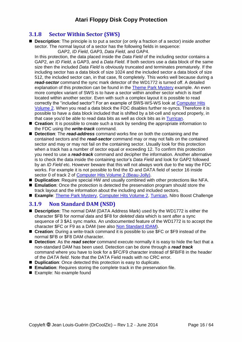
3.1.8 Sector Within Sector (SWS) Description: The principle is to put a sector (or only a fraction of a sector) inside another
sector. The normal layout of a sector has the following fields in sequence: GAP2, ID Field, GAP3, Data Field, and GAP4. In this protection, the data placed inside the Data Field of the including sector contains a GAP2, an ID Field, a GAP3, and a Data Field. If both sectors use a data block of the same size then the included Data Field is obviously truncated and terminates prematurely. If the including sector has a data block of size 1024 and the included sector a data block of size 512, the included sector can, in that case, fit completely. This works well because during a read-sector command the sync mark detector of the WD1772 is turned off. A detailed explanation of this protection can be found in the Theme Park Mystery example. An even more complex variant of SWS is to have a sector within another sector which is itself located within another sector. Even with such a complex layout it is possible to read correctly the “included sector”! For an example of SWS-WS-WS look at Computer Hits Volume 2. When you read a data block the FDC disables further re-syncs. Therefore it is possible to have a data block included that is shifted by a bit-cell and synced properly, in that case you'd be able to read data bits as well as clock bits as in Turrican.
Creation: It is possible to create such a track by sending the appropriate information to the FDC using the write-track command.
Detection: The read-address command works fine on both the containing and the contained sectors and the read-sector command may or may not fails on the contained sector and may or may not fail on the containing sector. Usually look for this protection when a track has a number of sector equal or exceeding 12. To confirm this protection you need to use a read-track command and decipher the information. Another alternative is to check the data inside the containing sector’s Data Field and look for GAP2 followed by an ID Field etc. However beware that this will not always work due to the way the FDC works. For example it is not possible to find the ID and DATA field of sector 16 inside sector 0 of track 2 of Computer Hits Volume 2 (Beau-Jolly).
Duplication: Require special HW and usually combined with other protections like NFA. Emulation: Once the protection is detected the preservation program should store the
track layout and the information about the including and included sectors. Example: Theme Park Mystery, Computer Hits Volume 2, Turrican, Nitro Boost Challenge
3.1.9 Non Standard DAM (NSD) Description: The normal DAM (DATA Address Mark) used by the WD1772 is either the
character $FB for normal data and $F8 for deleted data which is sent after a sync sequence of 3 $A1 sync marks. An undocumented feature of the WD1772 is to accept the character $FC or F9 as a DAM (see also Non Standard IDAM).
Creation: During a write-track command it is possible to use $FC or $F9 instead of the normal $FB or $F8 DAM character.
Detection: As the read sector command execute normally it is easy to hide the fact that a non-standard DAM has been used. Detection can be done through a read track command where you have to look for a $FC/F9 character instead of $FB/F8 in the header of the DATA field. Note that the DATA Field reads with no CRC error.
Duplication: Once detected this protection is easy to duplicate. Emulation: Requires storing the complete track in the preservation file. Example: No example found
Atari Floppy Disk Copy Protection
Copyleft Jean Louis-Guérin (DrCoolZic) – Rev 1.2 - June 2014 Page 17 / 64
3.1.10 Sector with No Data (SND) Description: A sector with an ID Field but not followed by a Data Field. Creation: It is quite easy to format a sector of a track with an ID field not followed by a
Data Field. This is done by sending appropriate data to the FDC during a write-track command.
Detection: This kind of sector is found using a read-address command, but is not found using a read-sector command. This is because during the read-sector command the FDC expects to find a DAM/DDAM within 43 bytes from last ID Field CRC byte, if not the sector data is searched again for 5 revolutions and the command is terminated with the Record Not Found (RNF) Status bit set.
Duplication: Can easily be done by software. Emulation: Requires storing the track information in the preservation file. Example: Night Shift (US Gold) uses duplicate sectors 66 both of them having No Data
fields
3.1.11 Invalid Data CRC Sector (IDC) Description: A sector that has a CRC error in its Data Field. Creation: Easy during write-track command by using the same mechanism as described
in Invalid ID CRC (IIC). Detection: Can easily be done using a read-sector command. The data sector is read
normally but the CRC error status bit is set at the end of the command. Duplication: Can easily be done by software Emulation: The content of the sector should be stored as normal but the CRC error
indicator must be added to the preservation file. Example: Populous
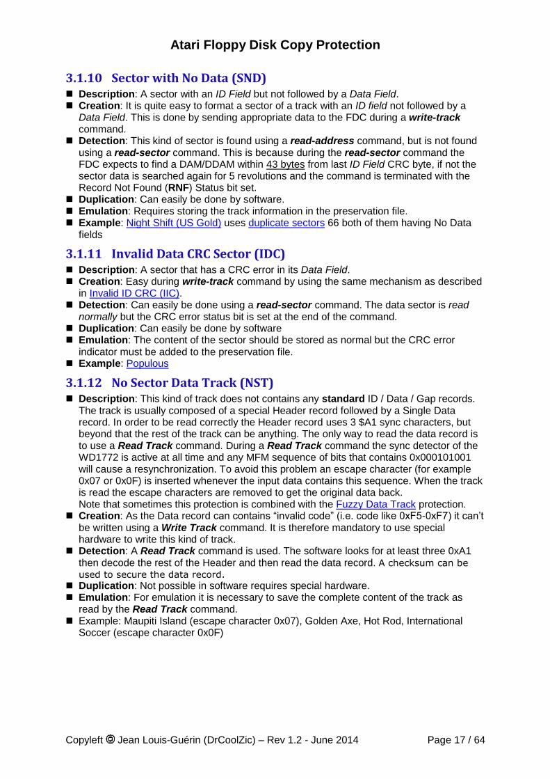
3.1.12 No Sector Data Track (NST) Description: This kind of track does not contains any standard ID / Data / Gap records.
The track is usually composed of a special Header record followed by a Single Data record. In order to be read correctly the Header record uses 3 $A1 sync characters, but beyond that the rest of the track can be anything. The only way to read the data record is to use a Read Track command. During a Read Track command the sync detector of the WD1772 is active at all time and any MFM sequence of bits that contains 0x000101001 will cause a resynchronization. To avoid this problem an escape character (for example 0x07 or 0x0F) is inserted whenever the input data contains this sequence. When the track is read the escape characters are removed to get the original data back. Note that sometimes this protection is combined with the Fuzzy Data Track protection.
Creation: As the Data record can contains “invalid code” (i.e. code like 0xF5-0xF7) it can’t be written using a Write Track command. It is therefore mandatory to use special hardware to write this kind of track.
Detection: A Read Track command is used. The software looks for at least three 0xA1 then decode the rest of the Header and then read the data record. A checksum can be
used to secure the data record. Duplication: Not possible in software requires special hardware. Emulation: For emulation it is necessary to save the complete content of the track as
read by the Read Track command. Example: Maupiti Island (escape character 0x07), Golden Axe, Hot Rod, International
Soccer (escape character 0x0F)
Atari Floppy Disk Copy Protection
Copyleft Jean Louis-Guérin (DrCoolZic) – Rev 1.2 - June 2014 Page 18 / 64
3.1.13 Hidden Data into GAP (HDG) Description: It is possible to write data into any gap. However the data are usually placed
in the post ID Gap (Gap of 22 bytes) or in the post DATA Gap (Gap of 40 bytes) as well as in the pre and post index GAP (respectively 664 and 60 bytes on standard diskettes). See “copy me I want to travel” from Claus Brod for a complete explanation and some interesting examples. For example some variation of the Copylock protections from 1988 store key value in the last two bytes (usually 00) of the pre index gap (just in front of the SYNC char).
Creation: Extra data can be written into Gap only during the write-track command. It is recommended to use Sync Marks in front of the data to be able to read them correctly (although reading pseudo random value may be part of the protection).
Detection: You need to use a read-track command to be able to read the inter-sector information. But it hard to find this information if you do not know what and where to look for. Therefore some heuristic need to be used (e.g. presence of sync marks into GAP).
Duplication: Although it is difficult to detect, it is easy to reproduce with the write-track command.
Emulation: Requires storing the track information in the preservation file. Example: Barbarian (end of Track 0) ?
3.1.14 Invalid Data in Gap (IDG) Description: During the format command character loaded into the data register of the
WD1772 is written to the disk. However the characters $F5 and $F6 are used to write the Sync Marks and the character $F7 is used to generate of two CRC bytes. This implies that it is not possible to have a character ranging from 245 through 247 ($F5-$F7) inside any of the GAPs3. Reading these characters into GAPs requires using a read-track command. In order for these invalid characters to be read correctly with a read-track command they are usually preceded by one or several sync character.
Creation: It is not possible with the WD1772 to write a character within the range 245-247 into any GAP. Therefore writing invalid character into GAPs requires special hardware.
Detection: Can easily be done with a read-track command. Duplication: Require special hardware. Emulation: It is necessary to save the complete content of the track. Example: Operation Neptune & Bob Morane .0 uses 0xF7 as gap bytes, Dragon Flight
3.1.15 Sync Mark in Data (SMD) Description: This is not a protection per se but it can be used as an indicator: During a
read-sector command the Sync Mark Detector of the WD1772 is disabled but during a read-track command the Sync Mark Detector is active at all time. For specific sequence of data bits during a read-track the detector detects a $C2 sync mark resulting in a shift of the following bits/bytes. This “feature” can be used to hide some information inside a Data Field (see “copy me I want to travel” from Claus Brod for examples).
Creation: You have to write a specific sequence of bits, known to create a false $C2 sync mark, within a Data Field during a write-track command. Note that these sequences rely on a poorly defined $C2 Sync Mark and are well known and described in many places.
Detection: Read with a read-sector command, then read with a read-track command and compare the returned data.
Emulation: Requires storing the track information in the preservation file. Duplication: Easy by software. Example: Turrican (shift to clock bits)
3 Note that it is not possible to modify the GAP2 or GAP3b ($00). Therefore writing hidden bytes must be done in GAP1 and/or GAP3a and/or GAP4
Atari Floppy Disk Copy Protection
Copyleft Jean Louis-Guérin (DrCoolZic) – Rev 1.2 - June 2014 Page 19 / 64
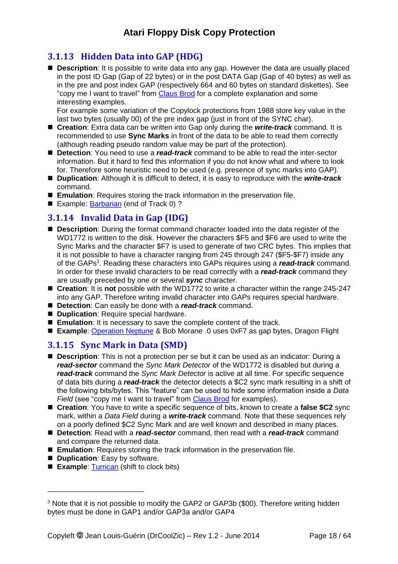
3.1.16 Invalid Sync-mark Sequence (ISS) Description: Normally Sync mark should always be in a sequence of 3 Sync Marks (3
$A1or 3 $C2) and should always been followed by an Address Mark (IAM = $FC, IDAM = $FE, DAM = $FB, or DDAM = $F8). Therefore having a sequence of 3 Sync Marks not followed by an AM is considered as an abnormal condition. Note that such sequence can usually be used to sync up the data separator to read data into gap or for No Sector Data Track. But it is also abnormal to have less than 2 or more than 3 Sync Marks in sequence. However finding only two Sync Marks with a read-track command is usually normal as the first Sync Mark is not read correctly.
Creation: It is quite easy to create an invalid sync mark sequence during format by sending appropriate information to the FDC using the write-track command.
Detection: Only possible with the read-track command as the read-sector command just ignore invalid sync mark sequences.
Emulation: Requires storing the track information in the preservation file. Duplication: Easy by software. Example: Barbarian (one Sync alone on Track 0, series of Sync on Track 48 & 62)
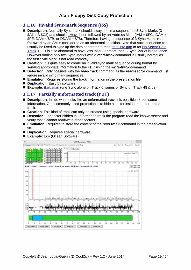
3.1.17 Partially unformatted track (PUT) Description: Inside what looks like an unformatted track it is possible to hide some
information. One commonly used protection is to hide a sector inside the unformatted track.
Creation: This kind of track can only be created using special hardware. Detection: For sector hidden in unformatted track the program read the known sector and
verify that it cannot read/write other sectors. Emulation: Requires to store the content of the read track command in the preservation
file. Duplication: Requires special hardware. Example: Eco (Ocean Software)
Atari Floppy Disk Copy Protection
Copyleft Jean Louis-Guérin (DrCoolZic) – Rev 1.2 - June 2014 Page 20 / 64
3.2 Protections based on Fuzzy Bits Fuzzy bits are known under many different names: weak bits, wandering bits, flaky bits, flakey bits, phantom bits, etc. Weak bits is the most commonly used term, however I find it confusing (as there is usually no “weakness” in weak bits). Therefore I prefer to use the term Fuzzy bits that does not suppose any underlying cause but clearly indicate the “fuzziness” of the returned data. Although fuzzy bits can be created by using different techniques the result is always the same: reading a byte that contains fuzzy bits will return random values (i.e. different value each time it is read). Fuzzy bytes could potentially be located at any place in a track but fuzzy bytes are usually placed in the data field of a sector. To provide complete information we will describe below several ways to create fuzzy bytes: Flux reversals in Ambiguous Area, Bit Cell Timing Violation, or Weak Bit. However for emulation or backup purpose it is not necessary to know underlying mechanism used.
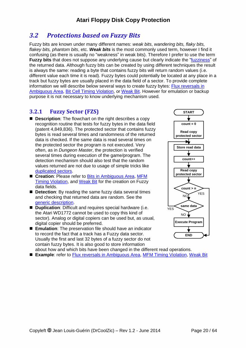
3.2.1 Fuzzy Sector (FZS) Description: The flowchart on the right describes a copy
recognition routine that tests for fuzzy bytes in the data field (patent 4,849,836). The protected sector that contains fuzzy bytes is read several times and randomness of the returned data is checked. If the same data is read several times on the protected sector the program is not executed. Very often, as in Dungeon Master, the protection is verified several times during execution of the game/program. The detection mechanism should also test that the random values returned are not due to usage of simple tricks like duplicated sectors.
Creation: Please refer to Bits in Ambiguous Area, MFM Timing Violation, and Weak Bit for the creation on Fuzzy data fields.
Detection: By reading the same fuzzy data several times and checking that returned data are random. See the generic description.
Duplication: Difficult and requires special hardware (i.e. the Atari WD1772 cannot be used to copy this kind of sector). Analog or digital copiers can be used but, as usual, digital copier should be preferred.
Emulation: The preservation file should have an indicator to record the fact that a track has a Fuzzy data sector. Usually the first and last 32 bytes of a fuzzy sector do not contain fuzzy bytes. It is also good to store information about how and which bits have been changed in the different read operations.
Example: refer to Flux reversals in Ambiguous Area, MFM Timing Violation, Weak Bit
START
Store read data
count = 0
Read copy
protected sector
count++
Read copy
protected sector
same data
count > n
Execute Program
END
YESNO
NO
YES
Atari Floppy Disk Copy Protection
Copyleft Jean Louis-Guérin (DrCoolZic) – Rev 1.2 - June 2014 Page 21 / 64
3.2.1.1 Flux Reversals in Ambiguous Area Description: These fuzzy bits are obtained by “placing” certain flux reversals in so called
“Ambiguous areas” i.e. at the border of the inspection window. Please refer to WD1772 Detection of Border Bits section for more information.
Creation: These fuzzy bits are obtained by placing the bit flux reversals in “Ambiguous areas”. More precisely the bit reversals are placed in locations that will confuse the DPLL (Digital Phase Lock Loop) of the data separator resulting in random values read (i.e. sometimes 0, sometimes 1). This is obtained by positioning the bit reversals at the border of the inspection window. In that case the data separator will return random values due to small variation of the drive rotation speed. In the US patent “Copy Protection for computer Disc 4,849,836” one of the techniques to create fuzzy bits consists in having flux reversals gradually sliding in and out of the inspection window border. Of course creating this kind of reversals requires special hardware that has capability to vary the FDC clock on the fly, or the capability to directly control the bit cell width/position (e.g. the Discovery Cartridge, KryoFlux board, SuperCard Pro device).
Detection: As mentioned this protection results in Fuzzy Sector. Therefore it can be detected by reading the same fuzzy sector (i.e. sector that contains fuzzy bits) several times and checking that returned data are random. Without specific hardware it is not possible to find the real underlying cause of the fuzzy bits but this information is of no use for an emulator or a duplicator.
Duplication: Difficult and requires special hardware (i.e. the Atari WD1772 cannot be used to copy this kind of bytes). Analog or digital copiers can be used but, as usual, digital copier should be preferred.
Emulation: The preservation file should have an indicator to record the fact that the sector is a fuzzy sector but should not care of the underlying cause of the fuzzy bits.
Example: Dungeon master Track 0, sector 7
3.2.1.2 MFM Timing Violation Description: These fuzzy bits are obtained by using flux reversals that violate the timing
of the MFM rules. Creation: These fuzzy bits are obtained by placing flux reversals that contains MFM
timing violations (data separated by less than 4 µs or more than 8 µs). For example a long series of zero data with missing clock bits. These bit-cell width are beyond the normal DPLL capture range and the next received reversal will be interpreted differently based on small random variation of the DPLL clock and/or the drive rotation speed. Of course this technique requires special hardware that has capability to vary the FDC clock on the fly, or the capability to directly control the bit cell width/position (e.g. the Discovery Cartridge). Note that this is often achieved by un-formatting a section of the track. See Unformatted Diskette / Track / Sector section for more information.
Detection: As mentioned this protection results in Fuzzy Sector. Therefore it can be detected by reading the same fuzzy sector (i.e. sector that contains fuzzy bits) several times and checking that returned data are random. Without specific hardware it is not possible to find the real underlying cause of the fuzzy bits but this information is of no use for an emulator or a duplicator.
Duplication: Difficult and requires special hardware (i.e. the Atari WD1772 cannot be used to copy this kind of bytes). Analog or digital copiers can be used but, as usual, digital copier should be preferred.
Emulation: The preservation file should have an indicator to record the fact that the sector is a fuzzy sector but should not care of the underlying cause of the fuzzy bits.
Example: D50 Editor - Track 0 - Sector 10.
Atari Floppy Disk Copy Protection
Copyleft Jean Louis-Guérin (DrCoolZic) – Rev 1.2 - June 2014 Page 22 / 64
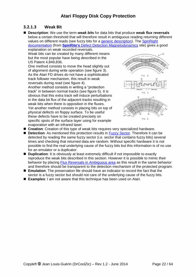
3.2.1.3 Weak Bit Description: We use the term weak bits for data bits that produce weak flux reversals
below a certain threshold that will therefore result in ambiguous reading returning different values on different reads (see fuzzy bits for a generic description). The SpinRight documentation (from SpinRite's Defect Detection Magnetodynamics site) gives a good explanation on weak recorded reversals. Weak bits can be created by many different means but the most popular have being described in the US Patent 4,849,836. One method consists to move the head slightly out of alignment during write operation (see figure 3). As the Atari FD drives do not have a sophisticated track follower mechanism, this result in weak reversals during read (see figure 4). Another method consists in writing a “protection track” in between normal tracks (see figure 5). It is obvious that this extra track will induce perturbations in the data bit flux of the adjacent tracks resulting in weak bits when there is opposition in the fluxes. Yet another method consists in placing bits on top of physical defects on floppy surface. To be useful these defects have to be created precisely on specific spots of the surface layer using for example evaporation with an infrared laser.
Creation: Creation of this type of weak bits requires very specialized hardware. Detection: As mentioned this protection results in Fuzzy Sector. Therefore it can be
detected by reading the same fuzzy sector (i.e. sector that contains fuzzy bits) several times and checking that returned data are random. Without specific hardware it is not possible to find the real underlying cause of the fuzzy bits but this information is of no use for an emulator or a duplicator.
Duplication: It is obviously at least extremely difficult if not impossible to exactly reproduce the weak bits described in this section. However it is possible to mimic their behavior by placing Flux Reversals in Ambiguous area as this result in the same behavior and therefore should be transparent to the detection mechanism of the protected program.
Emulation: The preservation file should have an indicator to record the fact that the sector is a fuzzy sector but should not care of the underlying cause of the fuzzy bits.
Examples: I am not aware that this technique has been used on Atari.
Atari Floppy Disk Copy Protection
Copyleft Jean Louis-Guérin (DrCoolZic) – Rev 1.2 - June 2014 Page 23 / 64
3.2.2 Fuzzy Track (FZT) Description: This is somewhat similar to Fuzzy Sector: the protected track that contains
fuzzy bytes is read several times and randomness of the returned data is checked. This is usually done in specific areas as explained below in Detection.
Creation: Please refer to Bits in Ambiguous Area, MFM Timing Violation, and Weak Bit for the creation on Fuzzy data fields.
Detection: If you know where to look for it is easy to read the same fuzzy data several times and to check that returned data are random. However detecting randomness in a read track without specific information is difficult because there are many reason why a read track returns random data: the head of the track until the first sync is random because the position where the read track starts vary, and the sector write splices also generates randomness.
Duplication: Requires special hardware (i.e. the Atari WD1772 cannot be used to copy this kind of sector). Analog or digital copiers can be used but, as usual, digital copier should be preferred.
Emulation: The preservation file should have an indicator to record the fact that a track has a Fuzzy data track. Note that Pasti STX does not support this kind of protection.
Examples: Power Drift (track 1 side A of floppy disk 2). Vroom.
3.2.3 No Flux Area (NFA)
This in not really a fuzzy byte technique but I have placed it in this section as it usually also results in fuzzy bytes. Description: A track that contains an abnormally very long area without any flux
transition read. Note that this is quite different from an unformatted area (no flux transition recorded). An unformatted area produces random bits due to the fact that the gain of the amplifier (ACG) on the read channel is pushed to its maximum picking up noise on the head. In order to produce such area some trick needs to be used as explained in the No Flux Area on Disk section. This area is extremely difficult to reproduce even with specialized HW.
Creation: Requires specific hardware. Detection: No Flux Area result in reading 0x0000 MFM word in the shift register (no clock
transition and no data transition). However with the WD1772 only data byte of the MFM word can be accessed and it is therefore not possible to check that the clock byte is also null. For that matter the NFA protection is usually coupled with another protection: Sector within sector where the included sector is shifted by a half-cell. This trick allows to read the clock bytes from the included sector. For more information refer to Checking NFA with the WD1772 section.
Duplication: Difficult and requires special hardware (i.e. the Atari WD1772 cannot be used to copy this kind of bytes). Analog or digital copiers can be used but, as usual, digital copier should be preferred.
Emulation: The preservation file need to save the track and also needs to save the two sectors that allow to read the data and the clock.
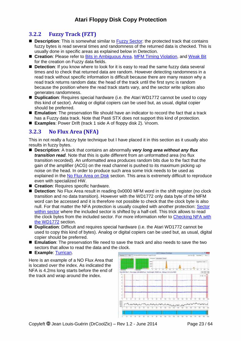
Example: Turrican.
Here is an example of a NO Flux Area that is located over the index. As indicated the NFA is 4.2ms long starts before the end of the track and wrap around the index.
Atari Floppy Disk Copy Protection
Copyleft Jean Louis-Guérin (DrCoolZic) – Rev 1.2 - June 2014 Page 24 / 64
3.3 Protections based on Bit-rate Variation This section describes the protections based on variations of the standard 4 µs cell bit-rate. Although different techniques are used the end result of using bit-rate variation is always the same: the overall time-length of a byte, transferred to/from the drive, is different from a “normal 32 µs byte”. Therefore detection of this protection requires to be able to measure timing information when reading a block of bytes and/or a sector.
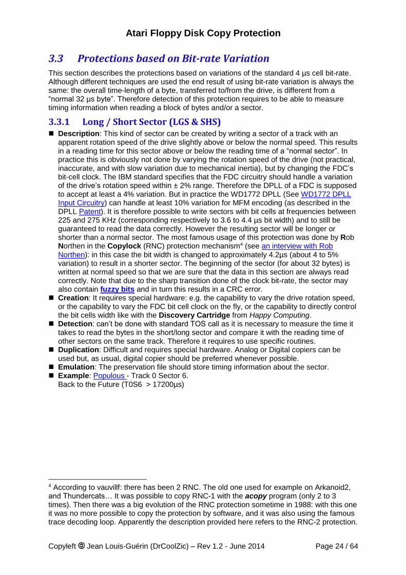
3.3.1 Long / Short Sector (LGS & SHS) Description: This kind of sector can be created by writing a sector of a track with an
apparent rotation speed of the drive slightly above or below the normal speed. This results in a reading time for this sector above or below the reading time of a “normal sector”. In practice this is obviously not done by varying the rotation speed of the drive (not practical, inaccurate, and with slow variation due to mechanical inertia), but by changing the FDC’s bit-cell clock. The IBM standard specifies that the FDC circuitry should handle a variation of the drive’s rotation speed within ± 2% range. Therefore the DPLL of a FDC is supposed to accept at least a 4% variation. But in practice the WD1772 DPLL (See WD1772 DPLL Input Circuitry) can handle at least 10% variation for MFM encoding (as described in the DPLL Patent). It is therefore possible to write sectors with bit cells at frequencies between 225 and 275 KHz (corresponding respectively to 3.6 to 4.4 µs bit width) and to still be guaranteed to read the data correctly. However the resulting sector will be longer or shorter than a normal sector. The most famous usage of this protection was done by Rob Northen in the Copylock (RNC) protection mechanism4 (see an interview with Rob Northen): in this case the bit width is changed to approximately 4.2µs (about 4 to 5% variation) to result in a shorter sector. The beginning of the sector (for about 32 bytes) is written at normal speed so that we are sure that the data in this section are always read correctly. Note that due to the sharp transition done of the clock bit-rate, the sector may also contain fuzzy bits and in turn this results in a CRC error.
Creation: It requires special hardware: e.g. the capability to vary the drive rotation speed, or the capability to vary the FDC bit cell clock on the fly, or the capability to directly control the bit cells width like with the Discovery Cartridge from Happy Computing.
Detection: can’t be done with standard TOS call as it is necessary to measure the time it takes to read the bytes in the short/long sector and compare it with the reading time of other sectors on the same track. Therefore it requires to use specific routines.
Duplication: Difficult and requires special hardware. Analog or Digital copiers can be used but, as usual, digital copier should be preferred whenever possible.
Emulation: The preservation file should store timing information about the sector. Example: Populous - Track 0 Sector 6.
Back to the Future (T0S6 > 17200µs)
4 According to vauvillf: there has been 2 RNC. The old one used for example on Arkanoid2, and Thundercats… It was possible to copy RNC-1 with the acopy program (only 2 to 3 times). Then there was a big evolution of the RNC protection sometime in 1988: with this one it was no more possible to copy the protection by software, and it was also using the famous trace decoding loop. Apparently the description provided here refers to the RNC-2 protection.
Atari Floppy Disk Copy Protection
Copyleft Jean Louis-Guérin (DrCoolZic) – Rev 1.2 - June 2014 Page 25 / 64
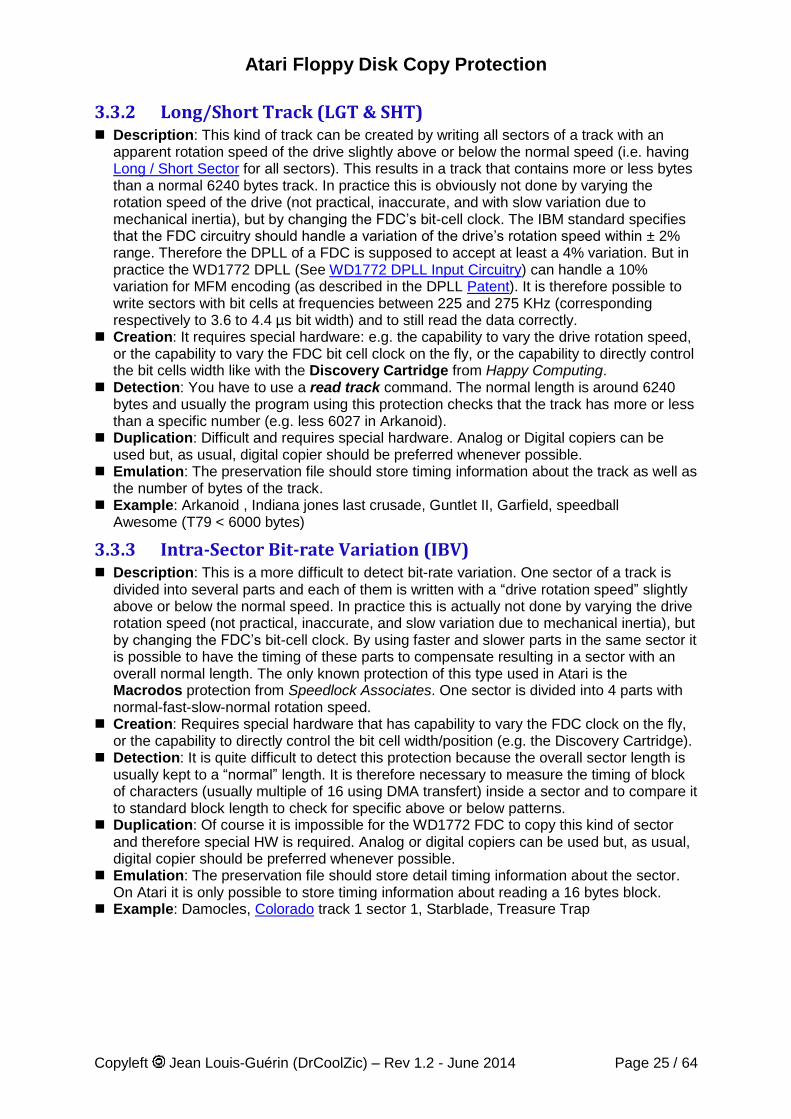
3.3.2 Long/Short Track (LGT & SHT) Description: This kind of track can be created by writing all sectors of a track with an
apparent rotation speed of the drive slightly above or below the normal speed (i.e. having Long / Short Sector for all sectors). This results in a track that contains more or less bytes than a normal 6240 bytes track. In practice this is obviously not done by varying the rotation speed of the drive (not practical, inaccurate, and with slow variation due to mechanical inertia), but by changing the FDC’s bit-cell clock. The IBM standard specifies that the FDC circuitry should handle a variation of the drive’s rotation speed within ± 2% range. Therefore the DPLL of a FDC is supposed to accept at least a 4% variation. But in practice the WD1772 DPLL (See WD1772 DPLL Input Circuitry) can handle a 10% variation for MFM encoding (as described in the DPLL Patent). It is therefore possible to write sectors with bit cells at frequencies between 225 and 275 KHz (corresponding respectively to 3.6 to 4.4 µs bit width) and to still read the data correctly.
Creation: It requires special hardware: e.g. the capability to vary the drive rotation speed, or the capability to vary the FDC bit cell clock on the fly, or the capability to directly control the bit cells width like with the Discovery Cartridge from Happy Computing.
Detection: You have to use a read track command. The normal length is around 6240 bytes and usually the program using this protection checks that the track has more or less than a specific number (e.g. less 6027 in Arkanoid).
Duplication: Difficult and requires special hardware. Analog or Digital copiers can be used but, as usual, digital copier should be preferred whenever possible.
Emulation: The preservation file should store timing information about the track as well as the number of bytes of the track.
Example: Arkanoid , Indiana jones last crusade, Guntlet II, Garfield, speedball Awesome (T79 < 6000 bytes)
3.3.3 Intra-Sector Bit-rate Variation (IBV) Description: This is a more difficult to detect bit-rate variation. One sector of a track is
divided into several parts and each of them is written with a “drive rotation speed” slightly above or below the normal speed. In practice this is actually not done by varying the drive rotation speed (not practical, inaccurate, and slow variation due to mechanical inertia), but by changing the FDC’s bit-cell clock. By using faster and slower parts in the same sector it is possible to have the timing of these parts to compensate resulting in a sector with an overall normal length. The only known protection of this type used in Atari is the Macrodos protection from Speedlock Associates. One sector is divided into 4 parts with normal-fast-slow-normal rotation speed.
Creation: Requires special hardware that has capability to vary the FDC clock on the fly, or the capability to directly control the bit cell width/position (e.g. the Discovery Cartridge).
Detection: It is quite difficult to detect this protection because the overall sector length is usually kept to a “normal” length. It is therefore necessary to measure the timing of block of characters (usually multiple of 16 using DMA transfert) inside a sector and to compare it to standard block length to check for specific above or below patterns.
Duplication: Of course it is impossible for the WD1772 FDC to copy this kind of sector and therefore special HW is required. Analog or digital copiers can be used but, as usual, digital copier should be preferred whenever possible.
Emulation: The preservation file should store detail timing information about the sector. On Atari it is only possible to store timing information about reading a 16 bytes block.
Example: Damocles, Colorado track 1 sector 1, Starblade, Treasure Trap
Atari Floppy Disk Copy Protection
Copyleft Jean Louis-Guérin (DrCoolZic) – Rev 1.2 - June 2014 Page 26 / 64
3.4 Protections based on Track Alteration This section is for reference only as I have never seen this kind of protection used with Atari floppy diskettes. They were mainly used on IBM platform with 5 ¼ diskettes.
These protections are based on physical alteration of a track resulting in “incorrect” results during reading. Sectors that contain these alterations are usually read with CRC error and possibly fuzzy bits.
3.4.1 Physical Alteration of Track Description: Obtained by physically altering a track: lots of techniques have been used
ranging from disk scratching to careful evaporation of surface layer with an infrared laser. These techniques (like making a small hole in the diskette surface with a laser) have been largely used with IBM and APPLE2 5 ¼ diskettes but as far as I know they have not been used on Atari.
Creation: Directly related to the defect and usually requires specific hardware. Detection: The physical defects produce default during reading (at least CRC error and
possibly fuzzy bits). Note that the original defects cannot always be positioned exactly and detection should take this into account.
Duplication: Normally not possible (although some people had developed expertise like in reproducing holes with a needle at the same exact disk location!), but approximation of equivalent defect can sometimes be created using CRC error and/or fuzzy bits.
Preservation: Same as for Fuzzy sector. Example: None on Atari?
Atari Floppy Disk Copy Protection
Copyleft Jean Louis-Guérin (DrCoolZic) – Rev 1.2 - June 2014 Page 27 / 64
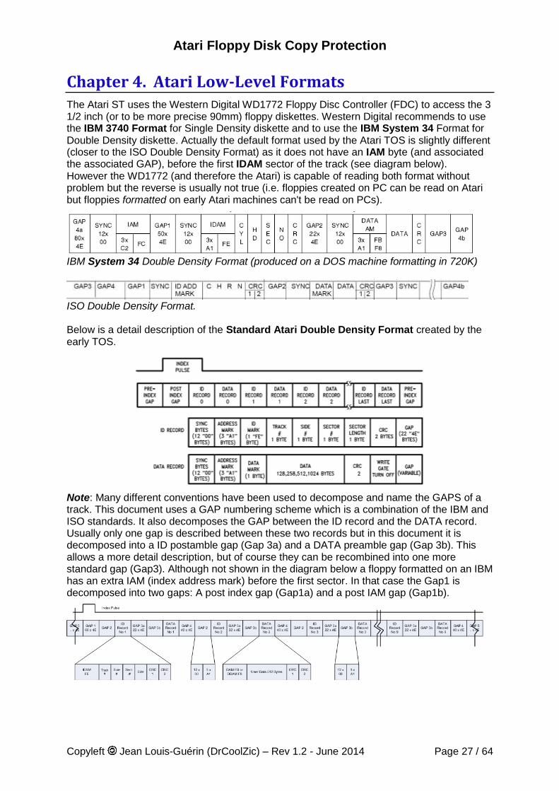
Chapter 4. Atari Low-Level Formats The Atari ST uses the Western Digital WD1772 Floppy Disc Controller (FDC) to access the 3 1/2 inch (or to be more precise 90mm) floppy diskettes. Western Digital recommends to use the IBM 3740 Format for Single Density diskette and to use the IBM System 34 Format for Double Density diskette. Actually the default format used by the Atari TOS is slightly different (closer to the ISO Double Density Format) as it does not have an IAM byte (and associated the associated GAP), before the first IDAM sector of the track (see diagram below). However the WD1772 (and therefore the Atari) is capable of reading both format without problem but the reverse is usually not true (i.e. floppies created on PC can be read on Atari but floppies formatted on early Atari machines can't be read on PCs).
IBM System 34 Double Density Format (produced on a DOS machine formatting in 720K)
ISO Double Density Format. Below is a detail description of the Standard Atari Double Density Format created by the early TOS.
Note: Many different conventions have been used to decompose and name the GAPS of a track. This document uses a GAP numbering scheme which is a combination of the IBM and ISO standards. It also decomposes the GAP between the ID record and the DATA record. Usually only one gap is described between these two records but in this document it is decomposed into a ID postamble gap (Gap 3a) and a DATA preamble gap (Gap 3b). This allows a more detail description, but of course they can be recombined into one more standard gap (Gap3). Although not shown in the diagram below a floppy formatted on an IBM has an extra IAM (index address mark) before the first sector. In that case the Gap1 is decomposed into two gaps: A post index gap (Gap1a) and a post IAM gap (Gap1b).
Atari Floppy Disk Copy Protection
Copyleft Jean Louis-Guérin (DrCoolZic) – Rev 1.2 - June 2014 Page 28 / 64
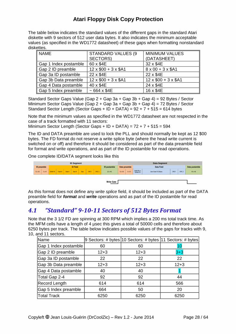
The table below indicates the standard values of the different gaps in the standard Atari diskette with 9 sectors of 512 user data bytes. It also indicates the minimum acceptable values (as specified in the WD1772 datasheet) of these gaps when formatting nonstandard diskettes.
NAME STANDARD VALUES (9 SECTORS)
MINIMUM VALUES (DATASHEET)
Gap 1 Index postamble 60 x $4E 32 x $4E Gap 2 ID preamble 12 x $00 + 3 x $A1 8 x 00 + 3 x $A1 Gap 3a ID postamble 22 x $4E 22 x $4E Gap 3b Data preamble 12 x $00 + 3 x $A1 12 x $00 + 3 x $A1 Gap 4 Data postamble 40 x $4E 24 x $4E Gap 5 Index preamble ~ 664 x $4E 16 x $4E
Standard Sector Gaps Value (Gap 2 + Gap 3a + Gap 3b + Gap 4) = 92 Bytes / Sector Minimum Sector Gaps Value (Gap 2 + Gap 3a + Gap 3b + Gap 4) = 72 Bytes / Sector Standard Sector Length (Sector Gaps + ID + DATA) = 92 + 7 + 515 = 614 bytes
Note that the minimum values as specified in the WD1772 datasheet are not respected in the case of a track formatted with 11 sectors: Minimum Sector Length (Sector Gaps + ID + DATA) = 72 + 7 + 515 = 594
The ID and DATA preamble are used to lock the PLL and should normally be kept as 12 $00 bytes. The FD format do not reserve a write splice byte (where the head write current is switched on or off) and therefore it should be considered as part of the data preamble field for format and write operations, and as part of the ID postamble for read operations.
One complete ID/DATA segment looks like this
22 x 4E 40 x 4E12 x 00 3 x A1DAM FB orDDAM F8 User Data 512 Bytes CRC1 CRC 212 x 00 3 x A1IDAM FE Track # Side # Sect # Size CRC1 CRC 2
Write Gate
ID Segment
ID Field ID postamble Data preamble Data Field Data postambleID preamble
Data Segment
As this format does not define any write splice field, it should be included as part of the DATA preamble field for format and write operations and as part of the ID postamble for read operations.
4.1 “Standard” 9-10-11 Sectors of 512 Bytes Format Note that the 3 1/2 FD are spinning at 300 RPM which implies a 200 ms total track time. As the MFM cells have a length of 4 µsec this gives a total of 50000 cells and therefore about 6250 bytes per track. The table below indicates possible values of the gaps for tracks with 9, 10, and 11 sectors.
Name 9 Sectors: # bytes 10 Sectors: # bytes 11 Sectors: # bytes
Gap 1 Index postamble 60 60 10
Gap 2 ID preamble 12+3 12+3 3+3
Gap 3a ID postamble 22 22 22
Gap 3b Data preamble 12+3 12+3 12+3
Gap 4 Data postamble 40 40 1
Total Gap 2-4 92 92 44
Record Length 614 614 566
Gap 5 Index preamble 664 50 20
Total Track 6250 6250 6250
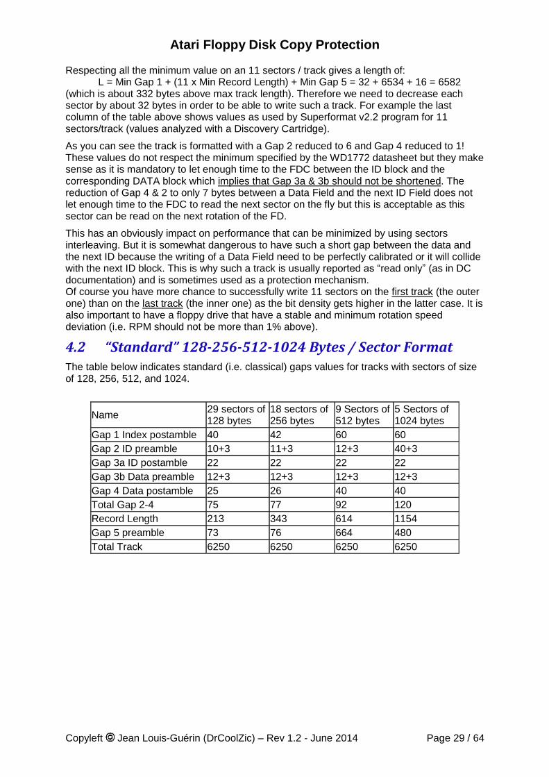
Atari Floppy Disk Copy Protection
Copyleft Jean Louis-Guérin (DrCoolZic) – Rev 1.2 - June 2014 Page 29 / 64
Respecting all the minimum value on an 11 sectors / track gives a length of: L = Min Gap 1 + (11 x Min Record Length) + Min Gap 5 = 32 + 6534 + 16 = 6582 (which is about 332 bytes above max track length). Therefore we need to decrease each sector by about 32 bytes in order to be able to write such a track. For example the last column of the table above shows values as used by Superformat v2.2 program for 11 sectors/track (values analyzed with a Discovery Cartridge).
As you can see the track is formatted with a Gap 2 reduced to 6 and Gap 4 reduced to 1! These values do not respect the minimum specified by the WD1772 datasheet but they make sense as it is mandatory to let enough time to the FDC between the ID block and the corresponding DATA block which implies that Gap 3a & 3b should not be shortened. The reduction of Gap 4 & 2 to only 7 bytes between a Data Field and the next ID Field does not let enough time to the FDC to read the next sector on the fly but this is acceptable as this sector can be read on the next rotation of the FD.
This has an obviously impact on performance that can be minimized by using sectors interleaving. But it is somewhat dangerous to have such a short gap between the data and the next ID because the writing of a Data Field need to be perfectly calibrated or it will collide with the next ID block. This is why such a track is usually reported as “read only” (as in DC documentation) and is sometimes used as a protection mechanism. Of course you have more chance to successfully write 11 sectors on the first track (the outer one) than on the last track (the inner one) as the bit density gets higher in the latter case. It is also important to have a floppy drive that have a stable and minimum rotation speed deviation (i.e. RPM should not be more than 1% above).
4.2 “Standard” 128-256-512-1024 Bytes / Sector Format The table below indicates standard (i.e. classical) gaps values for tracks with sectors of size of 128, 256, 512, and 1024.
Name 29 sectors of 128 bytes
18 sectors of 256 bytes
9 Sectors of 512 bytes
5 Sectors of 1024 bytes
Gap 1 Index postamble 40 42 60 60
Gap 2 ID preamble 10+3 11+3 12+3 40+3
Gap 3a ID postamble 22 22 22 22
Gap 3b Data preamble 12+3 12+3 12+3 12+3
Gap 4 Data postamble 25 26 40 40
Total Gap 2-4 75 77 92 120
Record Length 213 343 614 1154
Gap 5 preamble 73 76 664 480
Total Track 6250 6250 6250 6250
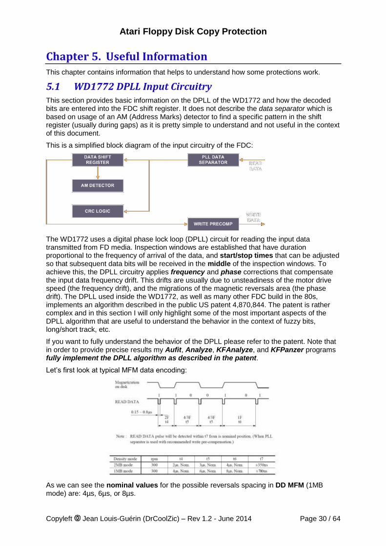
Atari Floppy Disk Copy Protection
Copyleft Jean Louis-Guérin (DrCoolZic) – Rev 1.2 - June 2014 Page 30 / 64
Chapter 5. Useful Information This chapter contains information that helps to understand how some protections work.
5.1 WD1772 DPLL Input Circuitry This section provides basic information on the DPLL of the WD1772 and how the decoded bits are entered into the FDC shift register. It does not describe the data separator which is based on usage of an AM (Address Marks) detector to find a specific pattern in the shift register (usually during gaps) as it is pretty simple to understand and not useful in the context of this document.
This is a simplified block diagram of the input circuitry of the FDC:
The WD1772 uses a digital phase lock loop (DPLL) circuit for reading the input data transmitted from FD media. Inspection windows are established that have duration proportional to the frequency of arrival of the data, and start/stop times that can be adjusted so that subsequent data bits will be received in the middle of the inspection windows. To achieve this, the DPLL circuitry applies frequency and phase corrections that compensate the input data frequency drift. This drifts are usually due to unsteadiness of the motor drive speed (the frequency drift), and the migrations of the magnetic reversals area (the phase drift). The DPLL used inside the WD1772, as well as many other FDC build in the 80s, implements an algorithm described in the public US patent 4,870,844. The patent is rather complex and in this section I will only highlight some of the most important aspects of the DPLL algorithm that are useful to understand the behavior in the context of fuzzy bits, long/short track, etc.
If you want to fully understand the behavior of the DPLL please refer to the patent. Note that in order to provide precise results my Aufit, Analyze, KFAnalyze, and KFPanzer programs fully implement the DPLL algorithm as described in the patent.
Let’s first look at typical MFM data encoding:
As we can see the nominal values for the possible reversals spacing in DD MFM (1MB mode) are: 4µs, 6µs, or 8µs.
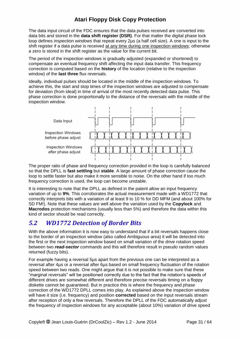
Atari Floppy Disk Copy Protection
Copyleft Jean Louis-Guérin (DrCoolZic) – Rev 1.2 - June 2014 Page 31 / 64
The data input circuit of the FDC ensures that the data pulses received are converted into data bits and stored in the data shift register (DSR). For that matter the digital phase lock loop defines inspection windows that repeat every 2µs (a half cell size). A one is input to the shift register if a data pulse is received at any time during one inspection windows; otherwise a zero is stored in the shift register as the value for the current bit.
The period of the inspection windows is gradually adjusted (expanded or shortened) to compensate an eventual frequency shift affecting the input data transfer. This frequency correction is computed based on the history of the location (relative to the inspection window) of the last three flux reversals.
Ideally, individual pulses should be located in the middle of the inspection windows. To achieve this, the start and stop times of the inspection windows are adjusted to compensate for deviation (from ideal) in time of arrival of the most recently detected data pulse. This phase correction is done proportionally to the distance of the reversals with the middle of the inspection window.
The proper ratio of phase and frequency correction provided in the loop is carefully balanced so that the DPLL is fast settling but stable. A large amount of phase correction cause the loop to settle faster but also make it more sensible to noise. On the other hand if too much frequency correction is used, the loop can become unstable.
It is interesting to note that the DPLL as defined in the patent allow an input frequency variation of up to 9%. This corroborates the actual measurement made with a WD1772 that correctly interprets bits with a variation of at least 9 to 10 % for DD MFM (and about 100% for SD FM!). Note that these values are well above the variation used by the Copylock and Macrodos protection mechanisms (usually less than 5%) and therefore the data within this kind of sector should be read correctly.
5.2 WD1772 Detection of Border Bits With the above information it is now easy to understand that if a bit reversals happens close to the border of an inspection window (also called Ambiguous area) it will be detected into the first or the next inspection window based on small variation of the drive rotation speed between two read-sector commands and this will therefore result in pseudo random values returned (fuzzy bits).
For example having a reversal 5µs apart from the previous one can be interpreted as a reversal after 4µs or a reversal after 6µs based on small frequency fluctuation of the rotation speed between two reads. One might argue that it is not possible to make sure that these “marginal reversals” will be positioned correctly due to the fact that the rotation’s speeds of different drives are somewhat different and therefore precise reversals timing on a floppy diskette cannot be guaranteed. But in practice this is where the frequency and phase correction of the WD1772 DPLL comes into play. As explained above the inspection window will have it size (i.e. frequency) and position corrected based on the input reversals stream after reception of only a few reversals. Therefore the DPLL of the FDC automatically adjust the frequency of inspection windows for any acceptable (about 10%) variation of drive speed
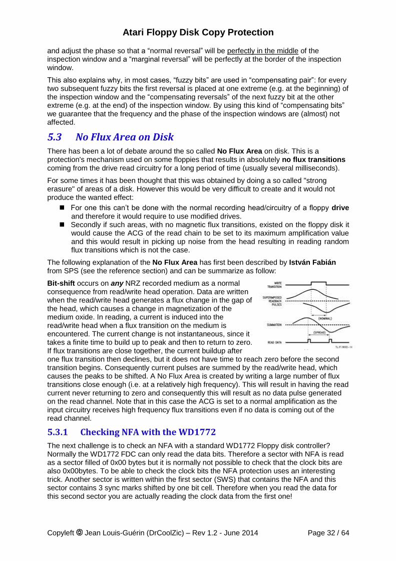
Atari Floppy Disk Copy Protection
Copyleft Jean Louis-Guérin (DrCoolZic) – Rev 1.2 - June 2014 Page 32 / 64
and adjust the phase so that a “normal reversal” will be perfectly in the middle of the inspection window and a “marginal reversal” will be perfectly at the border of the inspection window.
This also explains why, in most cases, “fuzzy bits” are used in “compensating pair”: for every two subsequent fuzzy bits the first reversal is placed at one extreme (e.g. at the beginning) of the inspection window and the “compensating reversals” of the next fuzzy bit at the other extreme (e.g. at the end) of the inspection window. By using this kind of “compensating bits” we guarantee that the frequency and the phase of the inspection windows are (almost) not affected.
5.3 No Flux Area on Disk There has been a lot of debate around the so called No Flux Area on disk. This is a protection's mechanism used on some floppies that results in absolutely no flux transitions coming from the drive read circuitry for a long period of time (usually several milliseconds).
For some times it has been thought that this was obtained by doing a so called "strong erasure" of areas of a disk. However this would be very difficult to create and it would not produce the wanted effect:
For one this can’t be done with the normal recording head/circuitry of a floppy drive and therefore it would require to use modified drives.
Secondly if such areas, with no magnetic flux transitions, existed on the floppy disk it would cause the ACG of the read chain to be set to its maximum amplification value and this would result in picking up noise from the head resulting in reading random flux transitions which is not the case.
The following explanation of the No Flux Area has first been described by István Fabián from SPS (see the reference section) and can be summarize as follow:
Bit-shift occurs on any NRZ recorded medium as a normal consequence from read/write head operation. Data are written when the read/write head generates a flux change in the gap of the head, which causes a change in magnetization of the medium oxide. In reading, a current is induced into the read/write head when a flux transition on the medium is encountered. The current change is not instantaneous, since it takes a finite time to build up to peak and then to return to zero. If flux transitions are close together, the current buildup after one flux transition then declines, but it does not have time to reach zero before the second transition begins. Consequently current pulses are summed by the read/write head, which causes the peaks to be shifted. A No Flux Area is created by writing a large number of flux transitions close enough (i.e. at a relatively high frequency). This will result in having the read current never returning to zero and consequently this will result as no data pulse generated on the read channel. Note that in this case the ACG is set to a normal amplification as the input circuitry receives high frequency flux transitions even if no data is coming out of the read channel.
5.3.1 Checking NFA with the WD1772
The next challenge is to check an NFA with a standard WD1772 Floppy disk controller? Normally the WD1772 FDC can only read the data bits. Therefore a sector with NFA is read as a sector filled of 0x00 bytes but it is normally not possible to check that the clock bits are also 0x00bytes. To be able to check the clock bits the NFA protection uses an interesting trick. Another sector is written within the first sector (SWS) that contains the NFA and this sector contains 3 sync marks shifted by one bit cell. Therefore when you read the data for this second sector you are actually reading the clock data from the first one!
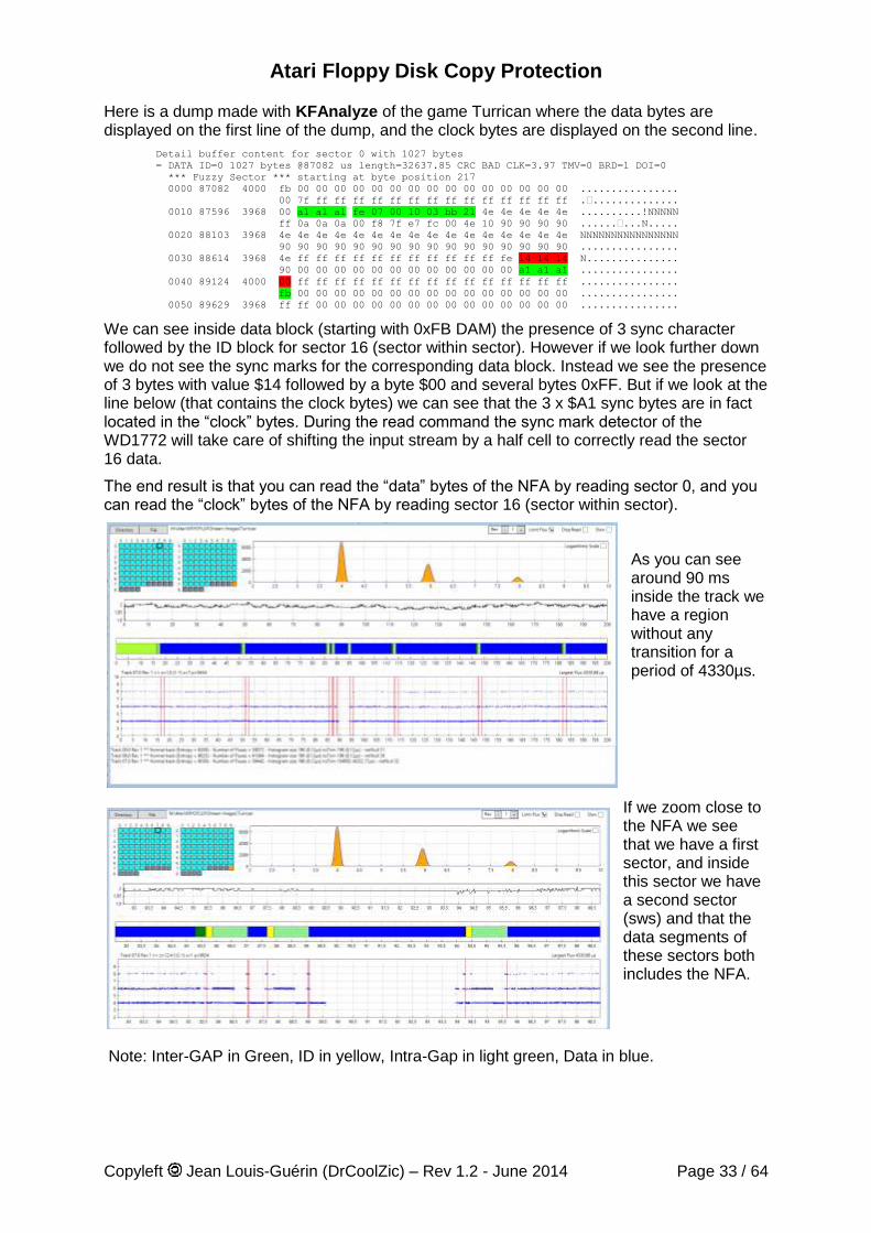
Atari Floppy Disk Copy Protection
Copyleft Jean Louis-Guérin (DrCoolZic) – Rev 1.2 - June 2014 Page 33 / 64
Here is a dump made with KFAnalyze of the game Turrican where the data bytes are displayed on the first line of the dump, and the clock bytes are displayed on the second line.
Detail buffer content for sector 0 with 1027 bytes
= DATA ID=0 1027 bytes @87082 us length=32637.85 CRC BAD CLK=3.97 TMV=0 BRD=1 DOI=0
*** Fuzzy Sector *** starting at byte position 217
0000 87082 4000 fb 00 00 00 00 00 00 00 00 00 00 00 00 00 00 00 ................
00 7f ff ff ff ff ff ff ff ff ff ff ff ff ff ff .•..............
0010 87596 3968 00 a1 a1 a1 fe 07 00 10 03 bb 21 4e 4e 4e 4e 4e ..........!NNNNN
ff 0a 0a 0a 00 f8 7f e7 fc 00 4e 10 90 90 90 90 ......•...N.....
0020 88103 3968 4e 4e 4e 4e 4e 4e 4e 4e 4e 4e 4e 4e 4e 4e 4e 4e NNNNNNNNNNNNNNNN
90 90 90 90 90 90 90 90 90 90 90 90 90 90 90 90 ................
0030 88614 3968 4e ff ff ff ff ff ff ff ff ff ff ff fe 14 14 14 N...............
90 00 00 00 00 00 00 00 00 00 00 00 00 a1 a1 a1 ................
0040 89124 4000 00 ff ff ff ff ff ff ff ff ff ff ff ff ff ff ff ................
fb 00 00 00 00 00 00 00 00 00 00 00 00 00 00 00 ................
0050 89629 3968 ff ff 00 00 00 00 00 00 00 00 00 00 00 00 00 00 ................
We can see inside data block (starting with 0xFB DAM) the presence of 3 sync character followed by the ID block for sector 16 (sector within sector). However if we look further down we do not see the sync marks for the corresponding data block. Instead we see the presence of 3 bytes with value $14 followed by a byte $00 and several bytes 0xFF. But if we look at the line below (that contains the clock bytes) we can see that the 3 x $A1 sync bytes are in fact located in the “clock” bytes. During the read command the sync mark detector of the WD1772 will take care of shifting the input stream by a half cell to correctly read the sector 16 data.
The end result is that you can read the “data” bytes of the NFA by reading sector 0, and you can read the “clock” bytes of the NFA by reading sector 16 (sector within sector).
As you can see around 90 ms inside the track we have a region without any transition for a period of 4330µs.
If we zoom close to the NFA we see that we have a first sector, and inside this sector we have a second sector (sws) and that the data segments of these sectors both includes the NFA.
Note: Inter-GAP in Green, ID in yellow, Intra-Gap in light green, Data in blue.
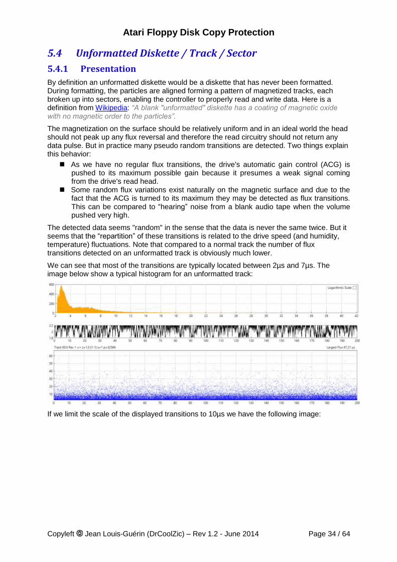
Atari Floppy Disk Copy Protection
Copyleft Jean Louis-Guérin (DrCoolZic) – Rev 1.2 - June 2014 Page 34 / 64
5.4 Unformatted Diskette / Track / Sector
5.4.1 Presentation
By definition an unformatted diskette would be a diskette that has never been formatted. During formatting, the particles are aligned forming a pattern of magnetized tracks, each broken up into sectors, enabling the controller to properly read and write data. Here is a definition from Wikipedia: “A blank "unformatted" diskette has a coating of magnetic oxide with no magnetic order to the particles”.
The magnetization on the surface should be relatively uniform and in an ideal world the head should not peak up any flux reversal and therefore the read circuitry should not return any data pulse. But in practice many pseudo random transitions are detected. Two things explain this behavior:
As we have no regular flux transitions, the drive's automatic gain control (ACG) is pushed to its maximum possible gain because it presumes a weak signal coming from the drive's read head.
Some random flux variations exist naturally on the magnetic surface and due to the fact that the ACG is turned to its maximum they may be detected as flux transitions. This can be compared to “hearing” noise from a blank audio tape when the volume pushed very high.
The detected data seems "random" in the sense that the data is never the same twice. But it seems that the “repartition” of these transitions is related to the drive speed (and humidity, temperature) fluctuations. Note that compared to a normal track the number of flux transitions detected on an unformatted track is obviously much lower.
We can see that most of the transitions are typically located between 2µs and 7µs. The image below show a typical histogram for an unformatted track:
If we limit the scale of the displayed transitions to 10µs we have the following image:
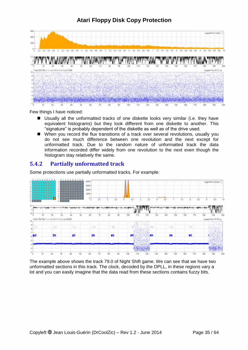
Atari Floppy Disk Copy Protection
Copyleft Jean Louis-Guérin (DrCoolZic) – Rev 1.2 - June 2014 Page 35 / 64
Few things I have noticed:
Usually all the unformatted tracks of one diskette looks very similar (i.e. they have equivalent histograms) but they look different from one diskette to another. This “signature” is probably dependent of the diskette as well as of the drive used.
When you record the flux transitions of a track over several revolutions, usually you do not see much difference between one revolution and the next except for unformatted track. Due to the random nature of unformatted track the data information recorded differ widely from one revolution to the next even though the histogram stay relatively the same.
5.4.2 Partially unformatted track
Some protections use partially unformatted tracks. For example:
The example above shows the track 79.0 of Night Shift game. We can see that we have two unformatted sections in this track. The clock, decoded by the DPLL, in these regions vary a lot and you can easily imagine that the data read from these sections contains fuzzy bits.
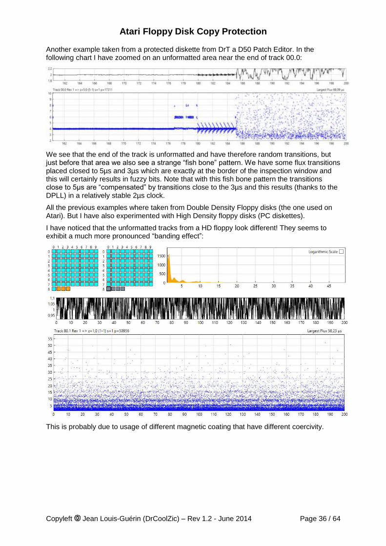
Atari Floppy Disk Copy Protection
Copyleft Jean Louis-Guérin (DrCoolZic) – Rev 1.2 - June 2014 Page 36 / 64
Another example taken from a protected diskette from DrT a D50 Patch Editor. In the following chart I have zoomed on an unformatted area near the end of track 00.0:
We see that the end of the track is unformatted and have therefore random transitions, but just before that area we also see a strange “fish bone” pattern. We have some flux transitions placed closed to 5µs and 3µs which are exactly at the border of the inspection window and this will certainly results in fuzzy bits. Note that with this fish bone pattern the transitions close to 5µs are “compensated” by transitions close to the 3µs and this results (thanks to the DPLL) in a relatively stable 2µs clock.
All the previous examples where taken from Double Density Floppy disks (the one used on Atari). But I have also experimented with High Density floppy disks (PC diskettes).
I have noticed that the unformatted tracks from a HD floppy look different! They seems to exhibit a much more pronounced “banding effect”:
This is probably due to usage of different magnetic coating that have different coercivity.
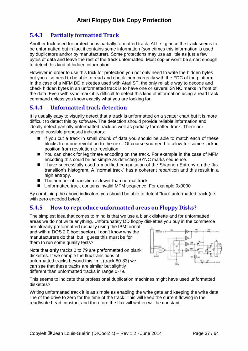
Atari Floppy Disk Copy Protection
Copyleft Jean Louis-Guérin (DrCoolZic) – Rev 1.2 - June 2014 Page 37 / 64
5.4.3 Partially formatted Track
Another trick used for protection is partially formatted track: At first glance the track seems to be unformatted but in fact it contains some information (sometimes this information is used by duplicators and/or by manufacturer). Some protections may use as little as just a few bytes of data and leave the rest of the track unformatted. Most copier won’t be smart enough to detect this kind of hidden information.
However in order to use this trick for protection you not only need to write the hidden bytes but you also need to be able to read and check them correctly with the FDC of the platform. In the case of a MFM DD diskettes used with Atari ST, the only reliable way to decode and check hidden bytes in an unformatted track is to have one or several SYNC marks in front of the data. Even with sync mark it is difficult to detect this kind of information using a read track command unless you know exactly what you are looking for.
5.4.4 Unformatted track detection
It is usually easy to visually detect that a track is unformatted on a scatter chart but it is more difficult to detect this by software. The detection should provide reliable information and ideally detect partially unformatted track as well as partially formatted track. There are several possible proposed indicators:
If you cut a track in small chunk of data you should be able to match each of these blocks from one revolution to the next. Of course you need to allow for some slack in position from revolution to revolution.
You can check for legitimate encoding on the track. For example in the case of MFM encoding this could be as simple as detecting SYNC marks sequence.
I have successfully used a modified computation of the Shannon Entropy on the flux transition’s histogram. A “normal track” has a coherent repartition and this result in a high entropy.
The number of transition is lower than normal track. Unformatted track contains invalid MFM sequence. For example 0x0000
By combining the above indicators you should be able to detect “true” unformatted track (i.e. with zero encoded bytes).
5.4.5 How to reproduce unformatted areas on Floppy Disks?
The simplest idea that comes to mind is that we use a blank diskette and for unformatted areas we do not write anything. Unfortunately DD floppy diskettes you buy in the commerce are already preformatted (usually using the IBM format and with a DOS 2.0 boot sector). I don’t know why the manufacturers do that, but I guess this must be for them to run some quality tests?
Note that only tracks 0 to 79 are preformatted on blank diskettes. If we sample the flux transitions of unformatted tracks beyond this limit (track 80-83) we can see that these tracks are similar but slightly different than unformatted tracks in range 0-79.
This seems to indicate that professional duplication machines might have used unformatted diskettes?
Writing unformatted track it is as simple as enabling the write gate and keeping the write data line of the drive to zero for the time of the track. This will keep the current flowing in the read/write head constant and therefore the flux will written will be constant.
Atari Floppy Disk Copy Protection
Copyleft Jean Louis-Guérin (DrCoolZic) – Rev 1.2 - June 2014 Page 38 / 64
The only potential problem comes from potential misalignment of the write head relative to previously written data. Hopefully the tunnel or straddle erase head should take care of the leftover of previous contents.
Remember that writing data on a floppy drive is different from the same operation on an audio tape drive. On an audio tape the information the data is first erase by an erase head then the new data is written linearly by the read/write head. On a floppy drive there is no erase head (other than the tunnel / straddle erase head used from trimming track) and the new data are just written over the existing one with the head operating at magnetic saturation.
To summarize: unformatting a track only requires to keep the write data line negated during the complete write operation. This is obviously not possible with a WD1772 FDC (it always pulse the write data line) but it is easy to control on a replicator (e.g. trace) or with a Kryoflux, SuperCard Pro device.
On an Atari the best you can do is to format a track using a buffer containing random bytes, but you will never get something similar to a real unformatted track because flux will always be located in the 4, 6, and 8 µs bands.
Atari Floppy Disk Copy Protection
Copyleft Jean Louis-Guérin (DrCoolZic) – Rev 1.2 - June 2014 Page 39 / 64
Chapter 6. Analysis of Games/Programs This section provides detailed analyses of some programs/games using key disk protection. The analyses have been done with the goal to illustrate the usage of the protections described in this document.
However it must be noted that: The presence of a described protection mechanism does not imply that it is actually used
because I have never checked the actual software used to test the protections. It is possible that for a game analyzed in this section more protections than the one
described exist. Beware that several releases of the same game may exist and may use different
protections. Only Original diskettes have been used (unless specifically noted). However it is difficult to
know for sure that a diskette has not been tampered. All the floppy diskettes tested are from the 80’s 90’s and might be damaged by time or
stress from the environment.
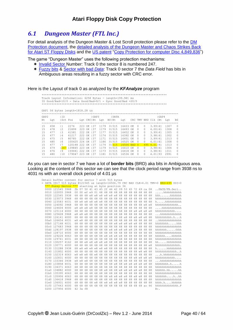
Atari Floppy Disk Copy Protection
Copyleft Jean Louis-Guérin (DrCoolZic) – Rev 1.2 - June 2014 Page 40 / 64
6.1 Dungeon Master (FTL Inc.) For detail analysis of the Dungeon Master & Lost Scroll protection please refer to the DM Protection document, the detailed analysis of the Dungeon Master and Chaos Strikes Back for Atari ST Floppy Disks and the US patent “Copy Protection for computer Disc 4,849,836”)
The game “Dungeon Master” uses the following protection mechanisms: Invalid Sector Number: Track 0 the sector 8 is numbered 247. Fuzzy bits & Sector with bad Data: Track 0 sector 7 the Data Field has bits in
Ambiguous areas resulting in a fuzzy sector with CRC error.
Here is the Layout of track 0 as analyzed by the KFAnalyze program
****************************************************************************
Track Layout Information: 6258 Bytes - length=199.981 ms
ID Good/Bad=10/0 - Data Good/Bad=9/1 - Sync Good/Bad =20/0
****************************************************************************
GAP1 56 bytes length=1818.28 us
-----------+------------------+-----------+---------------------------+------------
GAP2 |ID |GAP3 |DATA |GAP4
Bt Lgt |Sct Pos Lgt CRC|Bt Lgt BS|Bt Lgt CRC TMV BRD Clk |Bt Lgt BS
-----------+------------------+-----------+---------------------------+------------
15 458 |1 2276 223 OK |37 1179 0|515 16433 OK 0 0 3.99|41 1307 0
15 478 |2 21899 223 OK |37 1179 0|515 16493 OK 0 0 4.00|41 1308 0
15 477 |3 41581 222 OK |37 1177 0|515 16452 OK 0 0 3.99|41 1305 0
15 477 |4 61217 222 OK |37 1174 0|515 16392 OK 0 0 3.98|41 1302 0
15 475 |5 80785 222 OK |37 1171 0|515 16451 OK 0 0 3.99|41 1313 0
15 480 |6 100425 224 OK |37 1186 0|515 16525 OK 0 0 4.01|41 1308 0
15 477 |7 120148 222 OK |37 1174 0|515 16506 BAD 0 495 4.01|41 1313 0
15 479 |247 139845 223 OK |37 1179 0|515 16410 OK 0 0 3.98|41 1304 0
15 476 |9 159441 222 OK |37 1173 0|515 16418 OK 0 0 3.98|41 1311 0
15 480 |10 179047 223 OK |37 1181 0|515 16536 OK 0 0 4.01|93 2991 0
-----------+------------------+-----------+---------------------------+------------
As you can see in sector 7 we have a lot of border bits (BRD) aka bits in Ambiguous area. Looking at the content of this sector we can see that the clock period range from 3938 ns to 4031 ns with an overall clock period of 4.01 µs
Detail buffer content for sector 7 with 515 bytes
= DATA ID=7 515 bytes @121545 us length=16506.79 CRC BAD CLK=4.01 TMV=0 BRD=495 DOI=0
*** Fuzzy Sector *** starting at byte position 34
0000 121545 3968 fb 07 50 41 43 45 2f 46 42 09 53 65 72 69 ca 08 ..PACE/FB.Seri..
0010 122055 3968 00 00 ef e9 01 68 68 68 68 68 68 68 68 68 68 68 .....hhhhhhhhhhh
0020 122565 3938 68 68 68 e8 e8 e8 e8 e8 e8 68 68 68 68 68 68 68 hhh......hhhhhhh
0030 123073 3968 68 68 68 68 68 68 68 68 68 68 68 68 68 68 68 68 hhhhhhhhhhhhhhhh
0040 123583 4031 68 e8 e8 e8 e8 e8 68 68 68 68 68 68 68 68 68 68 h.....hhhhhhhhhh
0050 124092 3968 68 68 68 68 68 68 68 68 68 68 68 68 68 68 e8 e8 hhhhhhhhhhhhhh..
0060 124604 4000 e8 e8 e8 e8 68 68 68 68 68 68 68 68 68 68 68 68 ....hhhhhhhhhhhh
0070 125114 4000 68 68 68 68 68 68 68 68 68 68 68 68 e8 e8 e8 e8 hhhhhhhhhhhh....
0080 125628 3968 e8 e8 e8 68 68 68 68 68 68 68 68 68 68 68 68 68 ...hhhhhhhhhhhhh
0090 126141 4000 68 68 68 68 68 68 68 68 68 68 e8 68 e8 e8 e8 68 hhhhhhhhhh.h...h
00a0 126654 4031 e8 e8 68 68 68 68 68 68 68 68 68 68 68 68 68 68 ..hhhhhhhhhhhhhh
00b0 127168 4031 68 68 68 68 68 68 68 68 e8 e8 e8 e8 e8 68 68 68 hhhhhhhh.....hhh
00c0 127683 3968 68 68 68 68 68 68 68 68 68 68 68 68 68 68 68 68 hhhhhhhhhhhhhhhh
00d0 128197 3938 68 68 68 68 68 68 68 e8 e8 e8 e8 e8 28 68 68 68 hhhhhhh.....(hhh
00e0 128710 4000 68 68 68 68 68 68 68 68 68 68 68 68 68 68 68 68 hhhhhhhhhhhhhhhh
00f0 129226 4063 68 68 68 68 68 68 e8 e8 e8 e8 68 68 68 68 68 68 hhhhhh....hhhhhh
0100 129741 4031 68 68 68 68 68 68 68 68 68 68 68 68 68 68 68 68 hhhhhhhhhhhhhhhh
0110 130257 4162 68 68 e8 e8 e8 e8 e8 68 68 68 68 68 68 68 68 68 hh.....hhhhhhhhh
0120 130771 4000 68 68 68 68 68 68 68 68 68 68 68 68 68 68 68 e8 hhhhhhhhhhhhhhh.
0130 131288 3938 68 e8 e8 e8 e8 e8 e8 68 68 68 68 68 68 68 68 68 h......hhhhhhhhh
0140 131802 4000 68 68 68 68 68 68 68 68 68 68 68 68 68 e8 e8 68 hhhhhhhhhhhhh..h
0150 132319 4063 e8 e8 e8 68 e8 68 68 68 68 68 68 68 68 68 68 68 ...h.hhhhhhhhhhh
0160 132831 4000 68 68 68 68 68 68 68 68 68 68 68 68 e8 e8 e8 e8 hhhhhhhhhhhh....
0170 133346 3938 e8 e8 e8 68 68 68 68 68 68 68 68 68 68 68 68 68 ...hhhhhhhhhhhhh
0180 133858 4031 68 68 68 68 68 68 68 68 e8 68 e8 e8 e8 e8 e8 68 hhhhhhhh.h.....h
0190 134371 4063 68 68 68 68 68 68 68 68 68 68 68 68 68 68 68 68 hhhhhhhhhhhhhhhh
01a0 134882 4000 68 68 68 68 68 68 e8 68 68 e8 e8 e8 e8 e8 68 68 hhhhhh.hh.....hh
01b0 135395 4063 68 68 68 68 68 68 68 68 68 68 68 68 68 68 68 68 hhhhhhhhhhhhhhhh
01c0 135906 4063 68 68 68 68 68 68 68 e8 e8 e8 e8 68 e8 e8 68 68 hhhhhhh....h..hh
01d0 136418 3968 68 68 68 68 68 68 68 68 68 68 68 68 68 68 68 68 hhhhhhhhhhhhhhhh
01e0 136931 4000 68 68 68 68 e8 68 e8 e8 e8 e8 68 68 68 68 68 68 hhhh.h....hhhhhh
01f0 137443 4000 68 68 68 68 68 68 68 68 68 68 68 68 68 68 ac 46 hhhhhhhhhhhhhh.F
0200 137956 4000 42 3a f8 B:.
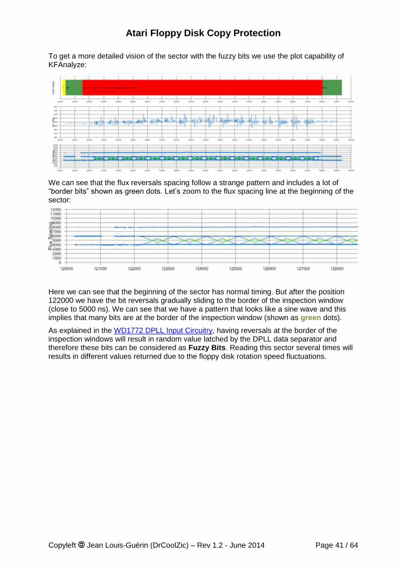
Atari Floppy Disk Copy Protection
Copyleft Jean Louis-Guérin (DrCoolZic) – Rev 1.2 - June 2014 Page 41 / 64
To get a more detailed vision of the sector with the fuzzy bits we use the plot capability of KFAnalyze:
We can see that the flux reversals spacing follow a strange pattern and includes a lot of “border bits” shown as green dots. Let’s zoom to the flux spacing line at the beginning of the sector:
Here we can see that the beginning of the sector has normal timing. But after the position 122000 we have the bit reversals gradually sliding to the border of the inspection window (close to 5000 ns). We can see that we have a pattern that looks like a sine wave and this implies that many bits are at the border of the inspection window (shown as green dots).
As explained in the WD1772 DPLL Input Circuitry, having reversals at the border of the inspection windows will result in random value latched by the DPLL data separator and therefore these bits can be considered as Fuzzy Bits. Reading this sector several times will results in different values returned due to the floppy disk rotation speed fluctuations.
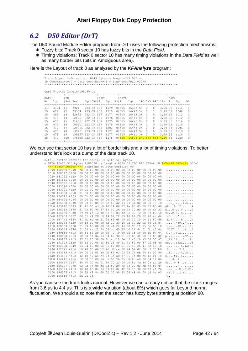
Atari Floppy Disk Copy Protection
Copyleft Jean Louis-Guérin (DrCoolZic) – Rev 1.2 - June 2014 Page 42 / 64
6.2 D50 Editor (DrT) The D50 Sound Module Editor program from DrT uses the following protection mechanisms: Fuzzy bits: Track 0 sector 10 has fuzzy bits in the Data Field. Timing violations: Track 0 sector 10 has many timing violations in the Data Field as well
as many border bits (bits in Ambiguous area).
Here is the Layout of track 0 as analyzed by the KFAnalyze program:
****************************************************************************
Track Layout Information: 6249 Bytes - length=199.976 ms
ID Good/Bad=10/0 - Data Good/Bad=9/1 - Sync Good/Bad =20/0
****************************************************************************
GAP1 5 bytes length=199.85 us
-----------+------------------+-----------+---------------------------+------------
GAP2 |ID |GAP3 |DATA |GAP4
Bt Lgt |Sct Pos Lgt CRC|Bt Lgt BS|Bt Lgt CRC TMV BRD Clk |Bt Lgt BS
-----------+------------------+-----------+---------------------------+------------
117 3724 |1 3924 223 OK |37 1179 0|515 16387 OK 0 0 3.98|35 1111 0
15 477 |2 23304 223 OK |38 1210 0|515 16442 OK 0 1 3.99|33 1048 0
15 465 |3 42694 222 OK |37 1177 0|515 16413 OK 0 0 3.98|35 1112 0
15 476 |4 62096 222 OK |37 1176 0|515 16410 OK 0 0 3.98|35 1112 0
15 476 |5 81496 222 OK |37 1175 0|515 16425 OK 0 0 3.99|35 1114 0
15 477 |6 100911 222 OK |37 1175 0|515 16414 OK 0 0 3.98|35 1115 0
15 477 |7 120316 222 OK |38 1202 0|515 16453 OK 0 0 3.99|34 1086 0
15 470 |8 139751 223 OK |37 1177 0|515 16447 OK 0 0 3.99|35 1119 0
15 478 |9 159197 223 OK |37 1177 0|515 16431 OK 0 0 3.99|35 1118 0
15 479 |10 178628 223 OK |37 1178 0|515 16895 BAD 849 815 4.10|88 3050 0
-----------+------------------+-----------+---------------------------+------------
We can see that sector 10 has a lot of border bits and a lot of timing violations. To better understand let’s look at a dump of the data track 10.
Detail buffer content for sector 10 with 515 bytes
= DATA ID=10 515 bytes @180030 us length=16895.59 CRC BAD CLK=4.10 TMV=849 BRD=815 DOI=0
*** Fuzzy Sector *** starting at byte position 80
0000 180030 4000 fb 00 00 00 00 00 00 00 00 00 00 00 00 00 00 00 ................
0010 180542 3968 00 00 00 00 00 00 00 00 00 00 00 00 00 00 00 00 ................
0020 181052 4129 00 00 00 00 00 00 00 00 00 00 00 00 00 00 00 00 ................
0030 181561 3968 00 00 00 00 00 00 00 00 00 00 00 00 00 00 00 00 ................
0040 182071 3968 00 00 00 00 00 00 00 00 00 00 00 00 00 00 00 00 ................
0050 182580 4000 00 00 00 00 00 00 00 00 00 00 00 00 00 00 00 00 ................
0060 183091 4129 00 01 00 00 00 00 00 00 00 00 00 00 00 00 00 00 ................
0070 183598 3968 01 00 00 00 00 00 00 00 00 00 00 00 00 00 00 00 ................
0080 184112 4129 00 01 00 00 00 00 00 00 00 00 00 00 00 00 00 00 ................
0090 184624 4096 00 00 00 00 00 00 00 00 00 00 00 00 00 00 00 00 ................
00a0 185138 4000 00 90 40 85 5f a2 f3 d2 13 83 31 82 30 00 18 18 ..@._.....1.0...
00b0 185612 3683 41 41 00 ad c0 40 14 00 37 1e 05 05 00 82 80 40 [email protected]......@
00c0 186112 3878 41 0c 90 90 47 11 00 26 1a 24 20 d0 10 c0 a4 53 A...G..&.$ ....S
00d0 186659 4338 39 40 0d 12 40 01 40 83 dc 35 32 12 00 84 08 60 9@..@[email protected]....`
00e0 187203 3657 60 61 44 20 c0 14 02 22 03 10 01 20 02 20 4a d4 `aD ..."... . J.
00f0 187742 4338 8f 4b 6e 46 21 94 85 d8 05 40 20 10 04 91 80 68 .KnF!....@ ....h
0100 188288 4129 09 18 00 08 60 d2 22 33 40 92 12 22 02 c5 1a c4 ....`."3@.."....
0110 188839 3968 21 00 00 00 00 c0 c4 24 44 08 93 11 d5 0e 5c 10 !......$D.....\.
0120 189349 4376 01 54 4a 21 54 04 cd 60 60 c0 14 6c 01 0b a5 4a .TJ!T..``..l...J
0130 189888 4413 28 84 8c 29 05 d0 70 19 58 c2 18 f0 ee 1b 97 04 (..)..p.X.......
0140 190428 4063 70 00 11 0e 93 84 00 98 b1 b1 8c 4f 50 c1 08 82 p..........OP...
0150 190977 4413 87 01 25 59 08 6c 4c 11 0e c2 43 20 a7 00 50 87 ..%Y.lL...C ..P.
0160 191523 3820 65 62 00 00 cf 80 26 40 41 41 82 00 87 02 08 40 eb....&@AA.....@
0170 192008 3849 04 04 00 00 16 06 02 00 01 35 fc 26 41 38 4b 10 .........5.&A8K.
0180 192521 4266 10 40 00 00 b2 2d d8 ce 50 94 52 0f 00 c3 75 b0 [email protected].
0190 193119 4413 b0 00 21 01 a8 0b 83 03 03 25 15 0b 44 a1 00 90 ..!......%..D...
01a0 193631 4413 42 10 42 a5 c4 74 3b a0 a7 36 1c 00 e8 15 01 10 B.B..t;..6......
01b0 194241 4266 10 00 13 00 64 c5 90 26 05 c0 8c a0 10 04 1f 06 ....d..&........
01c0 194697 3657 40 40 00 8a 01 30 20 23 06 b0 8b 7d 80 0a ac 26 @@...0 #...}...&
01d0 195177 3878 02 0a 1e 00 ca 8a f0 29 80 83 20 02 eb d8 86 84 .......).. .....
01e0 195729 4413 90 10 80 0a 04 09 09 04 42 00 18 30 d0 43 44 76 ........B..0.CDv
01f0 196275 4413 08 34 49 8c 28 02 00 90 32 04 48 80 00 c4 0a 03 .4I.(...2.H.....
0200 196819 4413 2a 21 1c *!.
As you can see the track looks normal. However we can already notice that the clock ranges from 3.6 µs to 4.4 µs. This is a wide variation (about 8%) which goes far beyond normal fluctuation. We should also note that the sector has fuzzy bytes starting at position 80.
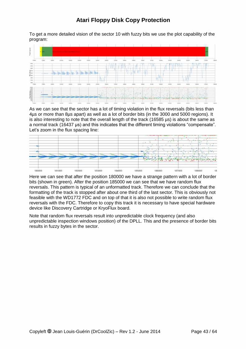
Atari Floppy Disk Copy Protection
Copyleft Jean Louis-Guérin (DrCoolZic) – Rev 1.2 - June 2014 Page 43 / 64
To get a more detailed vision of the sector 10 with fuzzy bits we use the plot capability of the program:
As we can see that the sector has a lot of timing violation in the flux reversals (bits less than 4µs or more than 8µs apart) as well as a lot of border bits (in the 3000 and 5000 regions). It is also interesting to note that the overall length of the track (16585 µs) is about the same as a normal track (16437 µs) and this indicates that the different timing violations “compensate”. Let’s zoom in the flux spacing line:
Here we can see that after the position 180000 we have a strange pattern with a lot of border bits (shown in green). After the position 185000 we can see that we have random flux reversals. This pattern is typical of an unformatted track. Therefore we can conclude that the formatting of the track is stopped after about one third of the last sector. This is obviously not feasible with the WD1772 FDC and on top of that it is also not possible to write random flux reversals with the FDC. Therefore to copy this track it is necessary to have special hardware device like Discovery Cartridge or KryoFlux board.
Note that random flux reversals result into unpredictable clock frequency (and also unpredictable inspection windows position) of the DPLL. This and the presence of border bits results in fuzzy bytes in the sector.
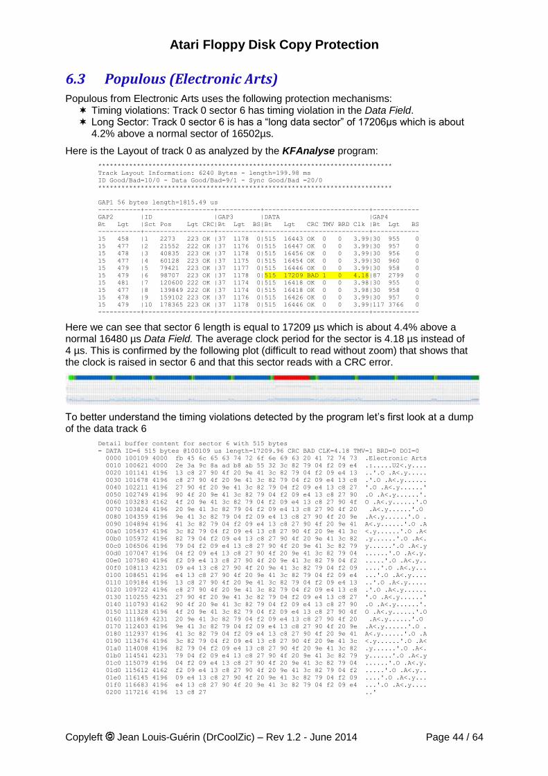
Atari Floppy Disk Copy Protection
Copyleft Jean Louis-Guérin (DrCoolZic) – Rev 1.2 - June 2014 Page 44 / 64
6.3 Populous (Electronic Arts) Populous from Electronic Arts uses the following protection mechanisms: Timing violations: Track 0 sector 6 has timing violation in the Data Field. Long Sector: Track 0 sector 6 is has a “long data sector” of 17206µs which is about
4.2% above a normal sector of 16502µs.
Here is the Layout of track 0 as analyzed by the KFAnalyse program:
****************************************************************************
Track Layout Information: 6240 Bytes - length=199.98 ms
ID Good/Bad=10/0 - Data Good/Bad=9/1 - Sync Good/Bad =20/0
****************************************************************************
GAP1 56 bytes length=1815.49 us
-----------+------------------+-----------+---------------------------+------------
GAP2 |ID |GAP3 |DATA |GAP4
Bt Lgt |Sct Pos Lgt CRC|Bt Lgt BS|Bt Lgt CRC TMV BRD Clk |Bt Lgt BS
-----------+------------------+-----------+---------------------------+------------
15 458 |1 2273 223 OK |37 1178 0|515 16443 OK 0 0 3.99|30 955 0
15 477 |2 21552 222 OK |37 1176 0|515 16447 OK 0 0 3.99|30 957 0
15 478 |3 40835 223 OK |37 1178 0|515 16456 OK 0 0 3.99|30 956 0
15 477 |4 60128 223 OK |37 1175 0|515 16454 OK 0 0 3.99|30 960 0
15 479 |5 79421 223 OK |37 1177 0|515 16446 OK 0 0 3.99|30 958 0
15 479 |6 98707 223 OK |37 1178 0|515 17209 BAD 1 0 4.18|87 2799 0
15 481 |7 120600 222 OK |37 1174 0|515 16418 OK 0 0 3.98|30 955 0
15 477 |8 139849 222 OK |37 1174 0|515 16418 OK 0 0 3.98|30 958 0
15 478 |9 159102 223 OK |37 1176 0|515 16426 OK 0 0 3.99|30 957 0
15 479 |10 178365 223 OK |37 1178 0|515 16446 OK 0 0 3.99|117 3766 0
-----------+------------------+-----------+---------------------------+------------
Here we can see that sector 6 length is equal to 17209 µs which is about 4.4% above a normal 16480 µs Data Field. The average clock period for the sector is 4.18 µs instead of 4 µs. This is confirmed by the following plot (difficult to read without zoom) that shows that the clock is raised in sector 6 and that this sector reads with a CRC error.
To better understand the timing violations detected by the program let’s first look at a dump of the data track 6
Detail buffer content for sector 6 with 515 bytes
= DATA ID=6 515 bytes @100109 us length=17209.96 CRC BAD CLK=4.18 TMV=1 BRD=0 DOI=0
0000 100109 4000 fb 45 6c 65 63 74 72 6f 6e 69 63 20 41 72 74 73 .Electronic Arts
0010 100621 4000 2e 3a 9c 8a ad b8 ab 55 32 3c 82 79 04 f2 09 e4 .:.....U2<.y....
0020 101141 4196 13 c8 27 90 4f 20 9e 41 3c 82 79 04 f2 09 e4 13 ..'.O .A<.y.....
0030 101678 4196 c8 27 90 4f 20 9e 41 3c 82 79 04 f2 09 e4 13 c8 .'.O .A<.y......
0040 102211 4196 27 90 4f 20 9e 41 3c 82 79 04 f2 09 e4 13 c8 27 '.O .A<.y......'
0050 102749 4196 90 4f 20 9e 41 3c 82 79 04 f2 09 e4 13 c8 27 90 .O .A<.y......'.
0060 103283 4162 4f 20 9e 41 3c 82 79 04 f2 09 e4 13 c8 27 90 4f O .A<.y......'.O
0070 103824 4196 20 9e 41 3c 82 79 04 f2 09 e4 13 c8 27 90 4f 20 .A<.y......'.O
0080 104359 4196 9e 41 3c 82 79 04 f2 09 e4 13 c8 27 90 4f 20 9e .A<.y......'.O .
0090 104894 4196 41 3c 82 79 04 f2 09 e4 13 c8 27 90 4f 20 9e 41 A<.y......'.O .A
00a0 105437 4196 3c 82 79 04 f2 09 e4 13 c8 27 90 4f 20 9e 41 3c <.y......'.O .A<
00b0 105972 4196 82 79 04 f2 09 e4 13 c8 27 90 4f 20 9e 41 3c 82 .y......'.O .A<.
00c0 106506 4196 79 04 f2 09 e4 13 c8 27 90 4f 20 9e 41 3c 82 79 y......'.O .A<.y
00d0 107047 4196 04 f2 09 e4 13 c8 27 90 4f 20 9e 41 3c 82 79 04 ......'.O .A<.y.
00e0 107580 4196 f2 09 e4 13 c8 27 90 4f 20 9e 41 3c 82 79 04 f2 .....'.O .A<.y..
00f0 108113 4231 09 e4 13 c8 27 90 4f 20 9e 41 3c 82 79 04 f2 09 ....'.O .A<.y...
0100 108651 4196 e4 13 c8 27 90 4f 20 9e 41 3c 82 79 04 f2 09 e4 ...'.O .A<.y....
0110 109184 4196 13 c8 27 90 4f 20 9e 41 3c 82 79 04 f2 09 e4 13 ..'.O .A<.y.....
0120 109722 4196 c8 27 90 4f 20 9e 41 3c 82 79 04 f2 09 e4 13 c8 .'.O .A<.y......
0130 110255 4231 27 90 4f 20 9e 41 3c 82 79 04 f2 09 e4 13 c8 27 '.O .A<.y......'
0140 110793 4162 90 4f 20 9e 41 3c 82 79 04 f2 09 e4 13 c8 27 90 .O .A<.y......'.
0150 111328 4196 4f 20 9e 41 3c 82 79 04 f2 09 e4 13 c8 27 90 4f O .A<.y......'.O
0160 111869 4231 20 9e 41 3c 82 79 04 f2 09 e4 13 c8 27 90 4f 20 .A<.y......'.O
0170 112403 4196 9e 41 3c 82 79 04 f2 09 e4 13 c8 27 90 4f 20 9e .A<.y......'.O .
0180 112937 4196 41 3c 82 79 04 f2 09 e4 13 c8 27 90 4f 20 9e 41 A<.y......'.O .A
0190 113476 4196 3c 82 79 04 f2 09 e4 13 c8 27 90 4f 20 9e 41 3c <.y......'.O .A<
01a0 114008 4196 82 79 04 f2 09 e4 13 c8 27 90 4f 20 9e 41 3c 82 .y......'.O .A<.
01b0 114541 4231 79 04 f2 09 e4 13 c8 27 90 4f 20 9e 41 3c 82 79 y......'.O .A<.y
01c0 115079 4196 04 f2 09 e4 13 c8 27 90 4f 20 9e 41 3c 82 79 04 ......'.O .A<.y.
01d0 115612 4162 f2 09 e4 13 c8 27 90 4f 20 9e 41 3c 82 79 04 f2 .....'.O .A<.y..
01e0 116145 4196 09 e4 13 c8 27 90 4f 20 9e 41 3c 82 79 04 f2 09 ....'.O .A<.y...
01f0 116683 4196 e4 13 c8 27 90 4f 20 9e 41 3c 82 79 04 f2 09 e4 ...'.O .A<.y....
0200 117216 4196 13 c8 27 ..'
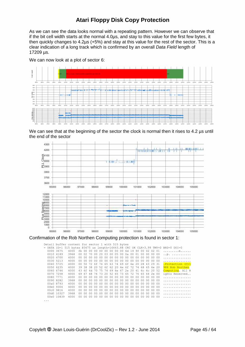
Atari Floppy Disk Copy Protection
Copyleft Jean Louis-Guérin (DrCoolZic) – Rev 1.2 - June 2014 Page 45 / 64
As we can see the data looks normal with a repeating pattern. However we can observe that if the bit cell width starts at the normal 4.0µs, and stay to this value for the first few bytes, it then quickly changes to 4.2µs (+5%) and stay at this value for the rest of the sector. This is a clear indication of a long track which is confirmed by an overall Data Field length of 17209 µs.
We can now look at a plot of sector 6:
We can see that at the beginning of the sector the clock is normal then it rises to 4.2 µs until the end of the sector
Confirmation of the Rob Northen Computing protection is found in sector 1:
Detail buffer content for sector 1 with 515 bytes
= DATA ID=1 515 bytes @3675 us length=16443.88 CRC OK CLK=3.99 TMV=0 BRD=0 DOI=0
0000 3675 4000 fb 00 00 00 00 00 00 00 00 6d 19 9f 00 02 02 01 .........m......
0010 4189 3968 00 02 70 00 20 03 00 05 00 0a 00 01 00 00 00 00 ..p. ...........
0020 4700 4000 00 00 00 00 00 00 00 00 00 00 00 00 00 00 00 00 ................
0030 5213 4000 00 00 00 00 00 00 00 00 00 00 00 00 00 00 00 00 ................
0040 5725 4000 00 50 72 6f 74 65 63 74 69 6f 6e 20 28 43 29 31 .Protection (C)1
0050 6235 4000 39 38 38 20 52 6f 62 20 4e 6f 72 74 68 65 6e 20 988 Rob Northen
0060 6746 4000 43 6f 6d 70 75 74 69 6e 67 2e 20 41 6c 6c 20 52 Computing. All R
0070 7258 4000 69 67 68 74 73 20 52 65 73 65 72 76 65 64 2e 00 ights Reserved..
0080 7771 4000 00 00 00 00 00 00 00 00 00 00 00 00 00 00 00 00 ................
0090 8282 3968 00 00 00 00 00 00 00 00 00 00 00 00 00 00 00 00 ................
00a0 8793 4000 00 00 00 00 00 00 00 00 00 00 00 00 00 00 00 00 ................
00b0 9304 4000 00 00 00 00 00 00 00 00 00 00 00 00 00 00 00 00 ................
00c0 9816 4000 00 00 00 00 00 00 00 00 00 00 00 00 00 00 00 00 ................
00d0 10327 3968 00 00 00 00 00 00 00 00 00 00 00 00 00 00 00 00 ................
00e0 10839 4000 00 00 00 00 00 00 00 00 00 00 00 00 00 00 00 00 ................
...
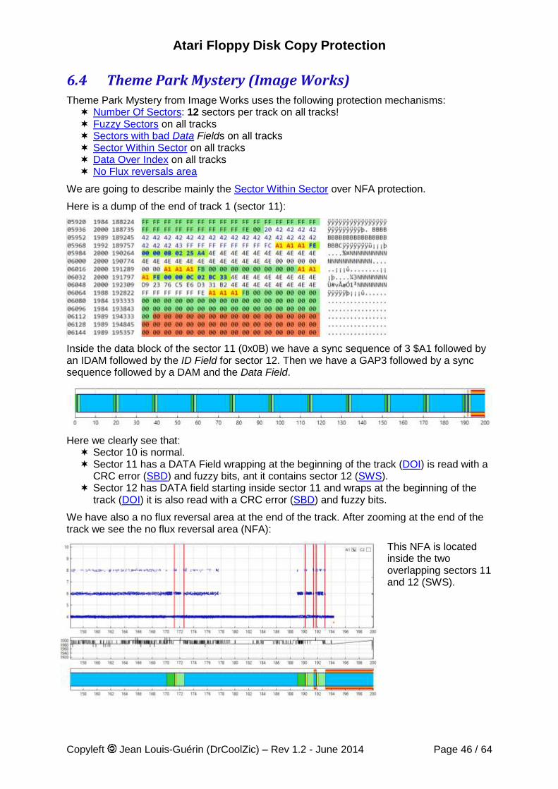
Atari Floppy Disk Copy Protection
Copyleft Jean Louis-Guérin (DrCoolZic) – Rev 1.2 - June 2014 Page 46 / 64
6.4 Theme Park Mystery (Image Works) Theme Park Mystery from Image Works uses the following protection mechanisms: Number Of Sectors: 12 sectors per track on all tracks! Fuzzy Sectors on all tracks Sectors with bad Data Fields on all tracks Sector Within Sector on all tracks Data Over Index on all tracks No Flux reversals area
We are going to describe mainly the Sector Within Sector over NFA protection.
Here is a dump of the end of track 1 (sector 11):
Inside the data block of the sector 11 (0x0B) we have a sync sequence of 3 $A1 followed by an IDAM followed by the ID Field for sector 12. Then we have a GAP3 followed by a sync sequence followed by a DAM and the Data Field.
Here we clearly see that: Sector 10 is normal. Sector 11 has a DATA Field wrapping at the beginning of the track (DOI) is read with a
CRC error (SBD) and fuzzy bits, ant it contains sector 12 (SWS). Sector 12 has DATA field starting inside sector 11 and wraps at the beginning of the
track (DOI) it is also read with a CRC error (SBD) and fuzzy bits.
We have also a no flux reversal area at the end of the track. After zooming at the end of the track we see the no flux reversal area (NFA):
This NFA is located inside the two overlapping sectors 11 and 12 (SWS).
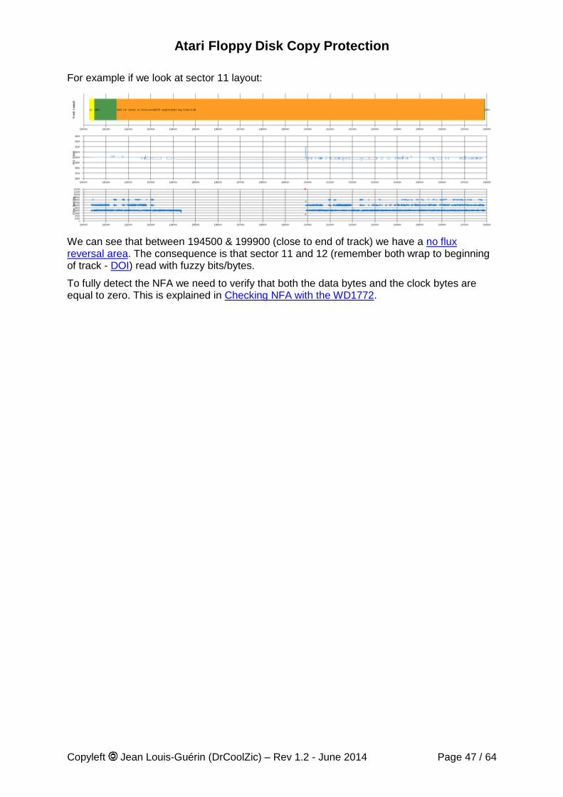
Atari Floppy Disk Copy Protection
Copyleft Jean Louis-Guérin (DrCoolZic) – Rev 1.2 - June 2014 Page 47 / 64
For example if we look at sector 11 layout:
We can see that between 194500 & 199900 (close to end of track) we have a no flux reversal area. The consequence is that sector 11 and 12 (remember both wrap to beginning of track - DOI) read with fuzzy bits/bytes.
To fully detect the NFA we need to verify that both the data bytes and the clock bytes are equal to zero. This is explained in Checking NFA with the WD1772.
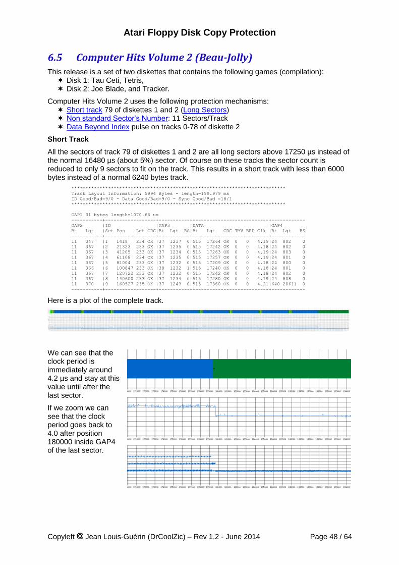
Atari Floppy Disk Copy Protection
Copyleft Jean Louis-Guérin (DrCoolZic) – Rev 1.2 - June 2014 Page 48 / 64
6.5 Computer Hits Volume 2 (Beau-Jolly) This release is a set of two diskettes that contains the following games (compilation): Disk 1: Tau Ceti, Tetris, Disk 2: Joe Blade, and Tracker.
Computer Hits Volume 2 uses the following protection mechanisms: Short track 79 of diskettes 1 and 2 (Long Sectors) Non standard Sector’s Number: 11 Sectors/Track Data Beyond Index pulse on tracks 0-78 of diskette 2
Short Track
All the sectors of track 79 of diskettes 1 and 2 are all long sectors above 17250 µs instead of the normal 16480 µs (about 5%) sector. Of course on these tracks the sector count is reduced to only 9 sectors to fit on the track. This results in a short track with less than 6000 bytes instead of a normal 6240 bytes track.
****************************************************************************
Track Layout Information: 5994 Bytes - length=199.979 ms
ID Good/Bad=9/0 - Data Good/Bad=9/0 - Sync Good/Bad =18/1
****************************************************************************
GAP1 31 bytes length=1070.66 us
-----------+------------------+-----------+---------------------------+------------
GAP2 |ID |GAP3 |DATA |GAP4
Bt Lgt |Sct Pos Lgt CRC|Bt Lgt BS|Bt Lgt CRC TMV BRD Clk |Bt Lgt BS
-----------+------------------+-----------+---------------------------+------------
11 347 |1 1418 234 OK |37 1237 0|515 17264 OK 0 0 4.19|24 802 0
11 367 |2 21323 233 OK |37 1235 0|515 17242 OK 0 0 4.18|24 802 0
11 367 |3 41205 233 OK |37 1234 0|515 17263 OK 0 0 4.19|24 803 0
11 367 |4 61108 234 OK |37 1235 0|515 17257 OK 0 0 4.19|24 801 0
11 367 |5 81004 233 OK |37 1232 0|515 17209 OK 0 0 4.18|24 800 0
11 366 |6 100847 233 OK |38 1232 1|515 17240 OK 0 0 4.18|24 801 0
11 367 |7 120722 233 OK |37 1232 0|515 17242 OK 0 0 4.18|24 802 0
11 367 |8 140600 233 OK |37 1234 0|515 17280 OK 0 0 4.19|24 808 0
11 370 |9 160527 235 OK |37 1243 0|515 17360 OK 0 0 4.21|640 20611 0
-----------+------------------+-----------+---------------------------+------------
Here is a plot of the complete track.
We can see that the clock period is immediately around 4.2 µs and stay at this value until after the last sector.
If we zoom we can see that the clock period goes back to 4.0 after position 180000 inside GAP4 of the last sector.
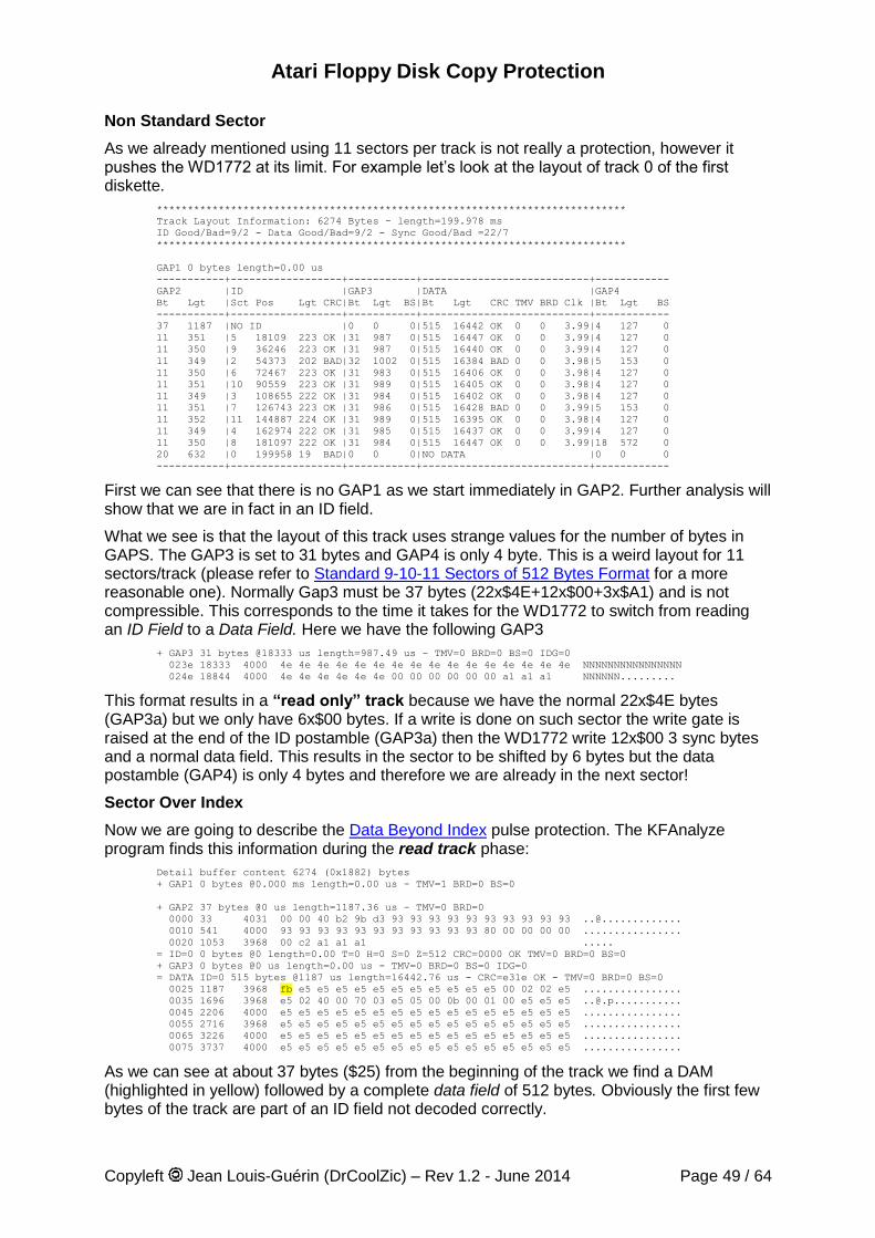
Atari Floppy Disk Copy Protection
Copyleft Jean Louis-Guérin (DrCoolZic) – Rev 1.2 - June 2014 Page 49 / 64
Non Standard Sector
As we already mentioned using 11 sectors per track is not really a protection, however it pushes the WD1772 at its limit. For example let’s look at the layout of track 0 of the first diskette.
****************************************************************************
Track Layout Information: 6274 Bytes - length=199.978 ms
ID Good/Bad=9/2 - Data Good/Bad=9/2 - Sync Good/Bad =22/7
****************************************************************************
GAP1 0 bytes length=0.00 us
-----------+------------------+-----------+---------------------------+------------
GAP2 |ID |GAP3 |DATA |GAP4
Bt Lgt |Sct Pos Lgt CRC|Bt Lgt BS|Bt Lgt CRC TMV BRD Clk |Bt Lgt BS
-----------+------------------+-----------+---------------------------+------------
37 1187 |NO ID |0 0 0|515 16442 OK 0 0 3.99|4 127 0
11 351 |5 18109 223 OK |31 987 0|515 16447 OK 0 0 3.99|4 127 0
11 350 |9 36246 223 OK |31 987 0|515 16440 OK 0 0 3.99|4 127 0
11 349 |2 54373 202 BAD|32 1002 0|515 16384 BAD 0 0 3.98|5 153 0
11 350 |6 72467 223 OK |31 983 0|515 16406 OK 0 0 3.98|4 127 0
11 351 |10 90559 223 OK |31 989 0|515 16405 OK 0 0 3.98|4 127 0
11 349 |3 108655 222 OK |31 984 0|515 16402 OK 0 0 3.98|4 127 0
11 351 |7 126743 223 OK |31 986 0|515 16428 BAD 0 0 3.99|5 153 0
11 352 |11 144887 224 OK |31 989 0|515 16395 OK 0 0 3.98|4 127 0
11 349 |4 162974 222 OK |31 985 0|515 16437 OK 0 0 3.99|4 127 0
11 350 |8 181097 222 OK |31 984 0|515 16447 OK 0 0 3.99|18 572 0
20 632 |0 199958 19 BAD|0 0 0|NO DATA |0 0 0
-----------+------------------+-----------+---------------------------+------------
First we can see that there is no GAP1 as we start immediately in GAP2. Further analysis will show that we are in fact in an ID field.
What we see is that the layout of this track uses strange values for the number of bytes in GAPS. The GAP3 is set to 31 bytes and GAP4 is only 4 byte. This is a weird layout for 11 sectors/track (please refer to Standard 9-10-11 Sectors of 512 Bytes Format for a more reasonable one). Normally Gap3 must be 37 bytes (22x$4E+12x$00+3x$A1) and is not compressible. This corresponds to the time it takes for the WD1772 to switch from reading an ID Field to a Data Field. Here we have the following GAP3
+ GAP3 31 bytes @18333 us length=987.49 us - TMV=0 BRD=0 BS=0 IDG=0
023e 18333 4000 4e 4e 4e 4e 4e 4e 4e 4e 4e 4e 4e 4e 4e 4e 4e 4e NNNNNNNNNNNNNNNN
024e 18844 4000 4e 4e 4e 4e 4e 4e 00 00 00 00 00 00 a1 a1 a1 NNNNNN.........
This format results in a “read only” track because we have the normal 22x$4E bytes (GAP3a) but we only have 6x$00 bytes. If a write is done on such sector the write gate is raised at the end of the ID postamble (GAP3a) then the WD1772 write 12x$00 3 sync bytes and a normal data field. This results in the sector to be shifted by 6 bytes but the data postamble (GAP4) is only 4 bytes and therefore we are already in the next sector!
Sector Over Index
Now we are going to describe the Data Beyond Index pulse protection. The KFAnalyze program finds this information during the read track phase:
Detail buffer content 6274 (0x1882) bytes
+ GAP1 0 bytes @0.000 ms length=0.00 us - TMV=1 BRD=0 BS=0
+ GAP2 37 bytes @0 us length=1187.36 us - TMV=0 BRD=0
0000 33 4031 00 00 40 b2 9b d3 93 93 93 93 93 93 93 93 93 93 ..@.............
0010 541 4000 93 93 93 93 93 93 93 93 93 93 93 80 00 00 00 00 ................
0020 1053 3968 00 c2 a1 a1 a1 .....
= ID=0 0 bytes @0 length=0.00 T=0 H=0 S=0 Z=512 CRC=0000 OK TMV=0 BRD=0 BS=0
+ GAP3 0 bytes @0 us length=0.00 us - TMV=0 BRD=0 BS=0 IDG=0
= DATA ID=0 515 bytes @1187 us length=16442.76 us - CRC=e31e OK - TMV=0 BRD=0 BS=0
0025 1187 3968 fb e5 e5 e5 e5 e5 e5 e5 e5 e5 e5 e5 00 02 02 e5 ................
0035 1696 3968 e5 02 40 00 70 03 e5 05 00 0b 00 01 00 e5 e5 e5 [email protected]...........
0045 2206 4000 e5 e5 e5 e5 e5 e5 e5 e5 e5 e5 e5 e5 e5 e5 e5 e5 ................
0055 2716 3968 e5 e5 e5 e5 e5 e5 e5 e5 e5 e5 e5 e5 e5 e5 e5 e5 ................
0065 3226 4000 e5 e5 e5 e5 e5 e5 e5 e5 e5 e5 e5 e5 e5 e5 e5 e5 ................
0075 3737 4000 e5 e5 e5 e5 e5 e5 e5 e5 e5 e5 e5 e5 e5 e5 e5 e5 ................
As we can see at about 37 bytes ($25) from the beginning of the track we find a DAM (highlighted in yellow) followed by a complete data field of 512 bytes. Obviously the first few bytes of the track are part of an ID field not decoded correctly.
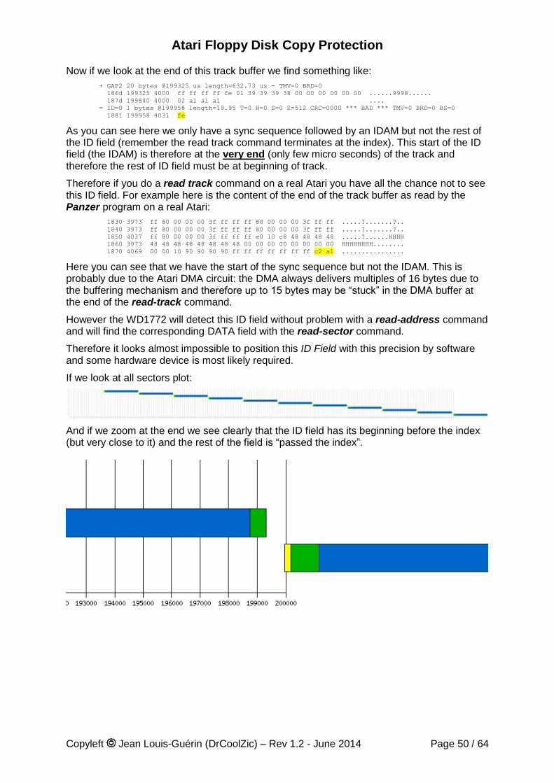
Atari Floppy Disk Copy Protection
Copyleft Jean Louis-Guérin (DrCoolZic) – Rev 1.2 - June 2014 Page 50 / 64
Now if we look at the end of this track buffer we find something like:
+ GAP2 20 bytes @199325 us length=632.73 us - TMV=0 BRD=0
186d 199325 4000 ff ff ff ff fe 01 39 39 39 38 00 00 00 00 00 00 ......9998......
187d 199840 4000 02 a1 a1 a1 ....
= ID=0 1 bytes @199958 length=19.95 T=0 H=0 S=0 Z=512 CRC=0000 *** BAD *** TMV=0 BRD=0 BS=0
1881 199958 4031 fe
As you can see here we only have a sync sequence followed by an IDAM but not the rest of the ID field (remember the read track command terminates at the index). This start of the ID field (the IDAM) is therefore at the very end (only few micro seconds) of the track and therefore the rest of ID field must be at beginning of track.
Therefore if you do a read track command on a real Atari you have all the chance not to see this ID field. For example here is the content of the end of the track buffer as read by the Panzer program on a real Atari:
1830 3973 ff 80 00 00 00 3f ff ff ff 80 00 00 00 3f ff ff .....?.......?..
1840 3973 ff 80 00 00 00 3f ff ff ff 80 00 00 00 3f ff ff .....?.......?..
1850 4037 ff 80 00 00 00 3f ff ff ff e0 10 c8 48 48 48 48 .....?......HHHH
1860 3973 48 48 48 48 48 48 48 48 00 00 00 00 00 00 00 00 HHHHHHHH........
1870 4069 00 00 10 90 90 90 90 ff ff ff ff ff ff ff c2 a1 ................
Here you can see that we have the start of the sync sequence but not the IDAM. This is probably due to the Atari DMA circuit: the DMA always delivers multiples of 16 bytes due to the buffering mechanism and therefore up to 15 bytes may be “stuck” in the DMA buffer at the end of the read-track command.
However the WD1772 will detect this ID field without problem with a read-address command and will find the corresponding DATA field with the read-sector command.
Therefore it looks almost impossible to position this ID Field with this precision by software and some hardware device is most likely required.
If we look at all sectors plot:
And if we zoom at the end we see clearly that the ID field has its beginning before the index (but very close to it) and the rest of the field is “passed the index”.
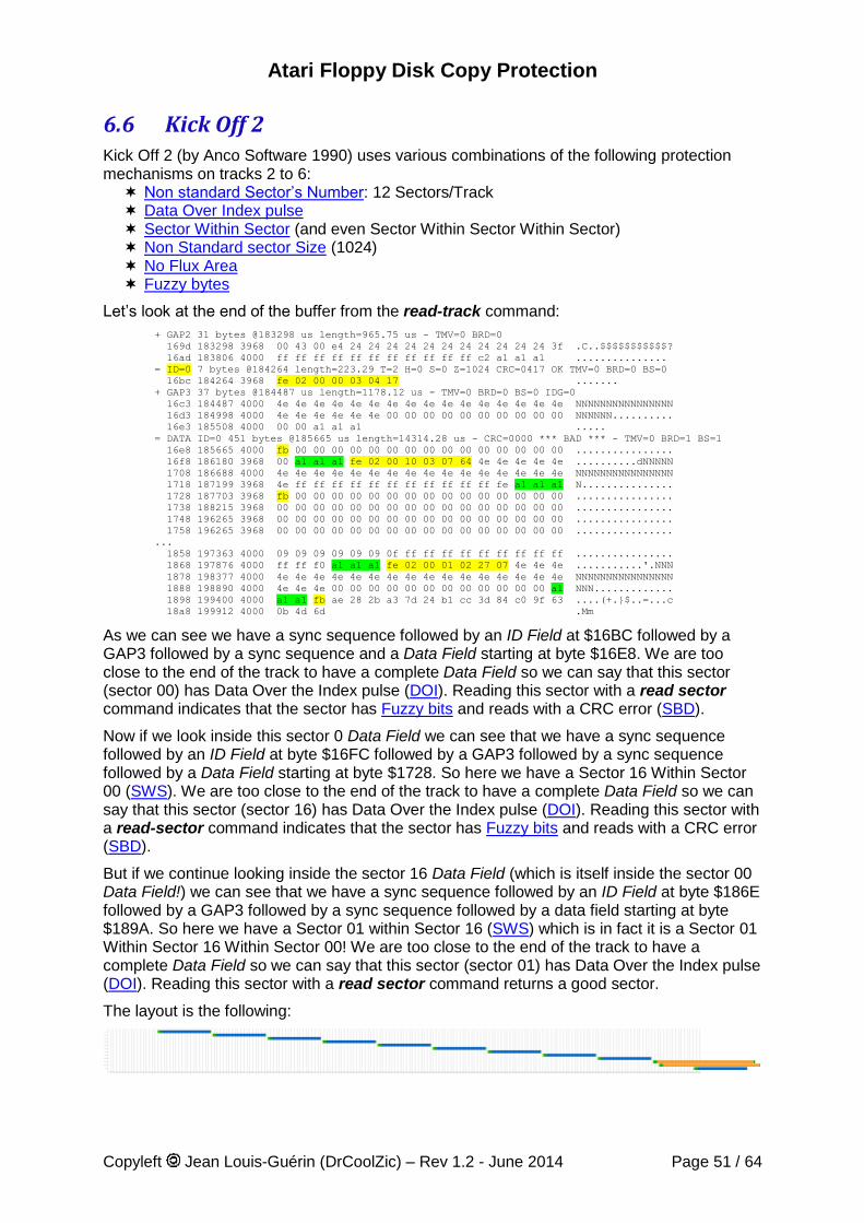
Atari Floppy Disk Copy Protection
Copyleft Jean Louis-Guérin (DrCoolZic) – Rev 1.2 - June 2014 Page 51 / 64
6.6 Kick Off 2 Kick Off 2 (by Anco Software 1990) uses various combinations of the following protection mechanisms on tracks 2 to 6: Non standard Sector’s Number: 12 Sectors/Track Data Over Index pulse Sector Within Sector (and even Sector Within Sector Within Sector) Non Standard sector Size (1024) No Flux Area Fuzzy bytes
Let’s look at the end of the buffer from the read-track command:
+ GAP2 31 bytes @183298 us length=965.75 us - TMV=0 BRD=0
169d 183298 3968 00 43 00 e4 24 24 24 24 24 24 24 24 24 24 24 3f .C..$$$$$$$$$$$?
16ad 183806 4000 ff ff ff ff ff ff ff ff ff ff ff c2 a1 a1 a1 ...............
= ID=0 7 bytes @184264 length=223.29 T=2 H=0 S=0 Z=1024 CRC=0417 OK TMV=0 BRD=0 BS=0
16bc 184264 3968 fe 02 00 00 03 04 17 .......
+ GAP3 37 bytes @184487 us length=1178.12 us - TMV=0 BRD=0 BS=0 IDG=0
16c3 184487 4000 4e 4e 4e 4e 4e 4e 4e 4e 4e 4e 4e 4e 4e 4e 4e 4e NNNNNNNNNNNNNNNN
16d3 184998 4000 4e 4e 4e 4e 4e 4e 00 00 00 00 00 00 00 00 00 00 NNNNNN..........
16e3 185508 4000 00 00 a1 a1 a1 .....
= DATA ID=0 451 bytes @185665 us length=14314.28 us - CRC=0000 *** BAD *** - TMV=0 BRD=1 BS=1
16e8 185665 4000 fb 00 00 00 00 00 00 00 00 00 00 00 00 00 00 00 ................
16f8 186180 3968 00 a1 a1 a1 fe 02 00 10 03 07 64 4e 4e 4e 4e 4e ..........dNNNNN
1708 186688 4000 4e 4e 4e 4e 4e 4e 4e 4e 4e 4e 4e 4e 4e 4e 4e 4e NNNNNNNNNNNNNNNN
1718 187199 3968 4e ff ff ff ff ff ff ff ff ff ff ff fe a1 a1 a1 N...............
1728 187703 3968 fb 00 00 00 00 00 00 00 00 00 00 00 00 00 00 00 ................
1738 188215 3968 00 00 00 00 00 00 00 00 00 00 00 00 00 00 00 00 ................
1748 196265 3968 00 00 00 00 00 00 00 00 00 00 00 00 00 00 00 00 ................
1758 196265 3968 00 00 00 00 00 00 00 00 00 00 00 00 00 00 00 00 ................
...
1858 197363 4000 09 09 09 09 09 09 0f ff ff ff ff ff ff ff ff ff ................
1868 197876 4000 ff ff f0 a1 a1 a1 fe 02 00 01 02 27 07 4e 4e 4e ...........'.NNN
1878 198377 4000 4e 4e 4e 4e 4e 4e 4e 4e 4e 4e 4e 4e 4e 4e 4e 4e NNNNNNNNNNNNNNNN
1888 198890 4000 4e 4e 4e 00 00 00 00 00 00 00 00 00 00 00 00 a1 NNN.............
1898 199400 4000 a1 a1 fb ae 28 2b a3 7d 24 b1 cc 3d 84 c0 9f 63 ....(+.}$..=...c
18a8 199912 4000 0b 4d 6d .Mm
As we can see we have a sync sequence followed by an ID Field at $16BC followed by a GAP3 followed by a sync sequence and a Data Field starting at byte $16E8. We are too close to the end of the track to have a complete Data Field so we can say that this sector (sector 00) has Data Over the Index pulse (DOI). Reading this sector with a read sector command indicates that the sector has Fuzzy bits and reads with a CRC error (SBD).
Now if we look inside this sector 0 Data Field we can see that we have a sync sequence followed by an ID Field at byte $16FC followed by a GAP3 followed by a sync sequence followed by a Data Field starting at byte $1728. So here we have a Sector 16 Within Sector 00 (SWS). We are too close to the end of the track to have a complete Data Field so we can say that this sector (sector 16) has Data Over the Index pulse (DOI). Reading this sector with a read-sector command indicates that the sector has Fuzzy bits and reads with a CRC error (SBD).
But if we continue looking inside the sector 16 Data Field (which is itself inside the sector 00 Data Field!) we can see that we have a sync sequence followed by an ID Field at byte $186E followed by a GAP3 followed by a sync sequence followed by a data field starting at byte $189A. So here we have a Sector 01 within Sector 16 (SWS) which is in fact it is a Sector 01 Within Sector 16 Within Sector 00! We are too close to the end of the track to have a complete Data Field so we can say that this sector (sector 01) has Data Over the Index pulse (DOI). Reading this sector with a read sector command returns a good sector.
The layout is the following:
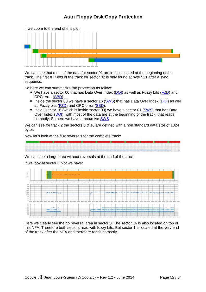
Atari Floppy Disk Copy Protection
Copyleft Jean Louis-Guérin (DrCoolZic) – Rev 1.2 - June 2014 Page 52 / 64
If we zoom to the end of this plot:
We can see that most of the data for sector 01 are in fact located at the beginning of the track. The first ID Field of the track for sector 02 is only found at byte 521 after a sync sequence.
So here we can summarize the protection as follow: We have a sector 00 that has Data Over Index (DOI) as well as Fuzzy bits (FZD) and
CRC error (SBD). Inside the sector 00 we have a sector 16 (SWS) that has Data Over Index (DOI) as well
as Fuzzy bits (FZD) and CRC error (SBD). Inside sector 16 (which is inside sector 00) we have a sector 01 (SWS) that has Data
Over Index (DOI), with most of the data are at the beginning of the track, that reads correctly. So here we have a recursive SWS
We can see for track 2 the sectors 0 & 16 are defined with a non standard data size of 1024 bytes
Now let’s look at the flux reversals for the complete track:
We can see a large area without reversals at the end of the track.
If we look at sector 0 plot we have:
Here we clearly see the no reversal area in sector 0. The sector 16 is also located on top of this NFA. Therefore both sectors read with fuzzy bits. But sector 1 is located at the very end of the track after the NFA and therefore reads correctly.
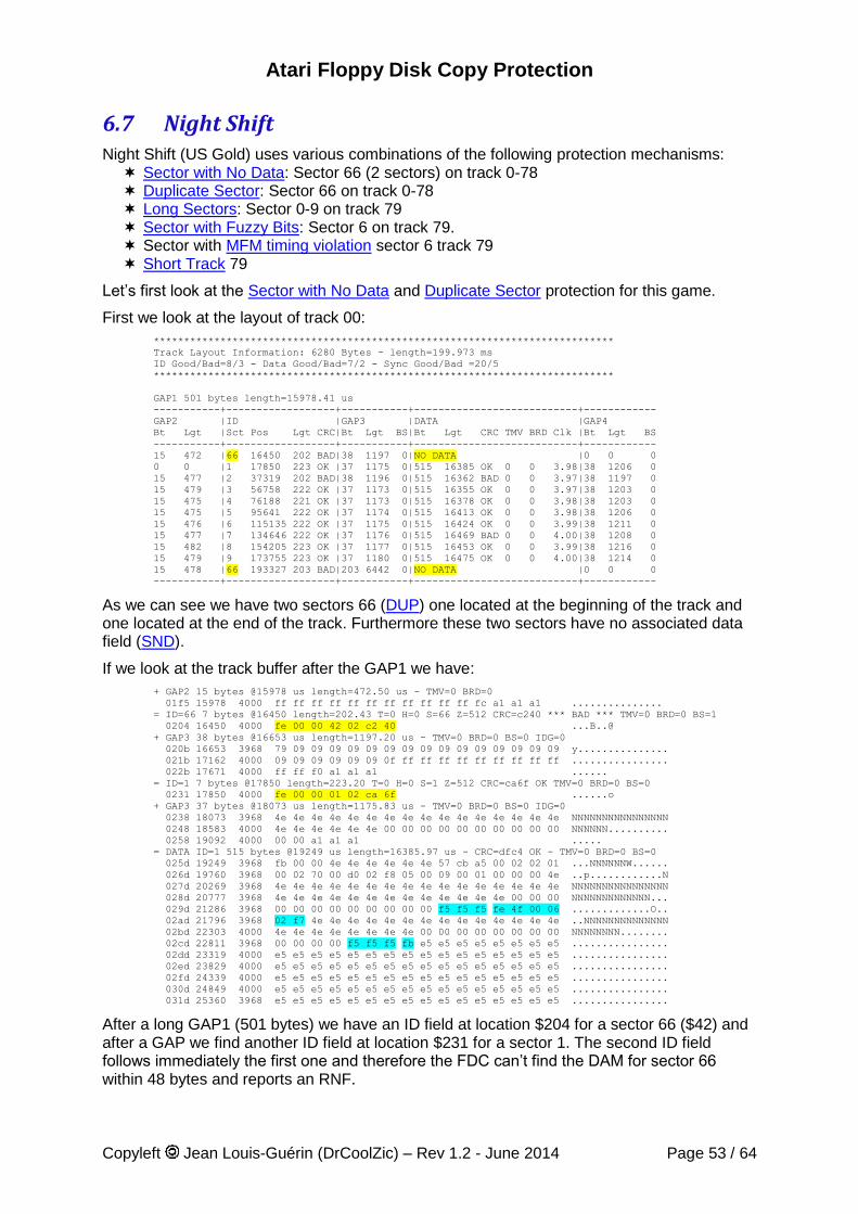
Atari Floppy Disk Copy Protection
Copyleft Jean Louis-Guérin (DrCoolZic) – Rev 1.2 - June 2014 Page 53 / 64
6.7 Night Shift Night Shift (US Gold) uses various combinations of the following protection mechanisms: Sector with No Data: Sector 66 (2 sectors) on track 0-78 Duplicate Sector: Sector 66 on track 0-78 Long Sectors: Sector 0-9 on track 79 Sector with Fuzzy Bits: Sector 6 on track 79. Sector with MFM timing violation sector 6 track 79 Short Track 79
Let’s first look at the Sector with No Data and Duplicate Sector protection for this game.
First we look at the layout of track 00:
****************************************************************************
Track Layout Information: 6280 Bytes - length=199.973 ms
ID Good/Bad=8/3 - Data Good/Bad=7/2 - Sync Good/Bad =20/5
****************************************************************************
GAP1 501 bytes length=15978.41 us
-----------+------------------+-----------+---------------------------+------------
GAP2 |ID |GAP3 |DATA |GAP4
Bt Lgt |Sct Pos Lgt CRC|Bt Lgt BS|Bt Lgt CRC TMV BRD Clk |Bt Lgt BS
-----------+------------------+-----------+---------------------------+------------
15 472 |66 16450 202 BAD|38 1197 0|NO DATA |0 0 0
0 0 |1 17850 223 OK |37 1175 0|515 16385 OK 0 0 3.98|38 1206 0
15 477 |2 37319 202 BAD|38 1196 0|515 16362 BAD 0 0 3.97|38 1197 0
15 479 |3 56758 222 OK |37 1173 0|515 16355 OK 0 0 3.97|38 1203 0
15 475 |4 76188 221 OK |37 1173 0|515 16378 OK 0 0 3.98|38 1203 0
15 475 |5 95641 222 OK |37 1174 0|515 16413 OK 0 0 3.98|38 1206 0
15 476 |6 115135 222 OK |37 1175 0|515 16424 OK 0 0 3.99|38 1211 0
15 477 |7 134646 222 OK |37 1176 0|515 16469 BAD 0 0 4.00|38 1208 0
15 482 |8 154205 223 OK |37 1177 0|515 16453 OK 0 0 3.99|38 1216 0
15 479 |9 173755 223 OK |37 1180 0|515 16475 OK 0 0 4.00|38 1214 0
15 478 |66 193327 203 BAD|203 6442 0|NO DATA |0 0 0
-----------+------------------+-----------+---------------------------+------------
As we can see we have two sectors 66 (DUP) one located at the beginning of the track and one located at the end of the track. Furthermore these two sectors have no associated data field (SND).
If we look at the track buffer after the GAP1 we have:
+ GAP2 15 bytes @15978 us length=472.50 us - TMV=0 BRD=0
01f5 15978 4000 ff ff ff ff ff ff ff ff ff ff ff fc a1 a1 a1 ...............
= ID=66 7 bytes @16450 length=202.43 T=0 H=0 S=66 Z=512 CRC=c240 *** BAD *** TMV=0 BRD=0 BS=1
0204 16450 4000 fe 00 00 42 02 c2 40 ...B..@
+ GAP3 38 bytes @16653 us length=1197.20 us - TMV=0 BRD=0 BS=0 IDG=0
020b 16653 3968 79 09 09 09 09 09 09 09 09 09 09 09 09 09 09 09 y...............
021b 17162 4000 09 09 09 09 09 09 0f ff ff ff ff ff ff ff ff ff ................
022b 17671 4000 ff ff f0 a1 a1 a1 ......
= ID=1 7 bytes @17850 length=223.20 T=0 H=0 S=1 Z=512 CRC=ca6f OK TMV=0 BRD=0 BS=0
0231 17850 4000 fe 00 00 01 02 ca 6f ......o
+ GAP3 37 bytes @18073 us length=1175.83 us - TMV=0 BRD=0 BS=0 IDG=0
0238 18073 3968 4e 4e 4e 4e 4e 4e 4e 4e 4e 4e 4e 4e 4e 4e 4e 4e NNNNNNNNNNNNNNNN
0248 18583 4000 4e 4e 4e 4e 4e 4e 00 00 00 00 00 00 00 00 00 00 NNNNNN..........
0258 19092 4000 00 00 a1 a1 a1 .....
= DATA ID=1 515 bytes @19249 us length=16385.97 us - CRC=dfc4 OK - TMV=0 BRD=0 BS=0
025d 19249 3968 fb 00 00 4e 4e 4e 4e 4e 4e 57 cb a5 00 02 02 01 ...NNNNNNW......
026d 19760 3968 00 02 70 00 d0 02 f8 05 00 09 00 01 00 00 00 4e ..p............N
027d 20269 3968 4e 4e 4e 4e 4e 4e 4e 4e 4e 4e 4e 4e 4e 4e 4e 4e NNNNNNNNNNNNNNNN
028d 20777 3968 4e 4e 4e 4e 4e 4e 4e 4e 4e 4e 4e 4e 4e 00 00 00 NNNNNNNNNNNNN...
029d 21286 3968 00 00 00 00 00 00 00 00 00 f5 f5 f5 fe 4f 00 06 .............O..
02ad 21796 3968 02 f7 4e 4e 4e 4e 4e 4e 4e 4e 4e 4e 4e 4e 4e 4e ..NNNNNNNNNNNNNN
02bd 22303 4000 4e 4e 4e 4e 4e 4e 4e 4e 00 00 00 00 00 00 00 00 NNNNNNNN........
02cd 22811 3968 00 00 00 00 f5 f5 f5 fb e5 e5 e5 e5 e5 e5 e5 e5 ................
02dd 23319 4000 e5 e5 e5 e5 e5 e5 e5 e5 e5 e5 e5 e5 e5 e5 e5 e5 ................
02ed 23829 4000 e5 e5 e5 e5 e5 e5 e5 e5 e5 e5 e5 e5 e5 e5 e5 e5 ................
02fd 24339 4000 e5 e5 e5 e5 e5 e5 e5 e5 e5 e5 e5 e5 e5 e5 e5 e5 ................
030d 24849 4000 e5 e5 e5 e5 e5 e5 e5 e5 e5 e5 e5 e5 e5 e5 e5 e5 ................
031d 25360 3968 e5 e5 e5 e5 e5 e5 e5 e5 e5 e5 e5 e5 e5 e5 e5 e5 ................
After a long GAP1 (501 bytes) we have an ID field at location $204 for a sector 66 ($42) and after a GAP we find another ID field at location $231 for a sector 1. The second ID field follows immediately the first one and therefore the FDC can’t find the DAM for sector 66 within 48 bytes and reports an RNF.
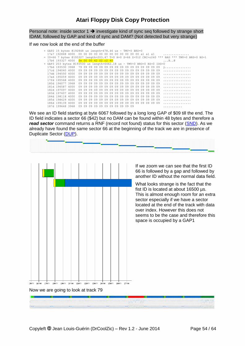
Atari Floppy Disk Copy Protection
Copyleft Jean Louis-Guérin (DrCoolZic) – Rev 1.2 - June 2014 Page 54 / 64
Personal note: inside sector 1 investigate kind of sync seq followed by strange short IDAM, followed by GAP and kind of sync and DAM? (Not detected but very strange)
If we now look at the end of the buffer
+ GAP2 15 bytes @192848 us length=478.46 us - TMV=0 BRD=0
17a7 192848 4000 00 00 00 00 00 00 00 00 00 00 00 00 a1 a1 a1 ...............
= ID=66 7 bytes @193327 length=203.47 T=0 H=0 S=66 Z=512 CRC=c240 *** BAD *** TMV=0 BRD=0 BS=1
17b6 193327 4000 fe 00 00 42 02 c2 40 ...B..@
+ GAP3 203 bytes @193530 us length=6442.18 us - TMV=0 BRD=0 BS=0 IDG=0
17bd 193530 3968 79 09 09 09 09 09 09 09 09 09 09 09 09 09 09 09 y...............
17cd 194040 4000 09 09 09 09 09 09 09 09 09 09 09 09 09 09 09 09 ................
17dd 194550 4000 09 09 09 09 09 09 09 09 09 09 09 09 09 09 09 09 ................
17ed 195059 4000 09 09 09 09 09 09 09 09 09 09 09 09 09 09 09 09 ................
17fd 195568 4000 09 09 09 09 09 09 09 09 09 09 09 09 09 09 09 09 ................
180d 196077 3968 09 09 09 09 09 09 09 09 09 09 09 09 09 09 09 09 ................
181d 196587 4000 09 09 09 09 09 09 09 09 09 09 09 09 09 09 09 09 ................
182d 197097 4000 09 09 09 09 09 09 09 09 09 09 09 09 09 09 09 09 ................
183d 197607 4000 09 09 09 09 09 09 09 09 09 09 09 09 09 09 09 09 ................
184d 198118 4000 09 09 09 09 09 09 09 09 09 09 09 09 09 09 09 09 ................
185d 198629 4000 09 09 09 09 09 09 09 09 09 09 09 09 09 09 09 09 ................
186d 199139 4000 09 09 09 09 09 09 09 09 09 09 09 09 09 09 09 09 ................
187d 199648 3968 09 09 09 09 09 09 09 09 09 09 09 ...........
We see an ID field starting at byte 6067 followed by a long long GAP of $09 till the end. The ID field indicates a sector 66 ($42) but no DAM can be found within 48 bytes and therefore a read sector command returns a RNF (record not found) status for this sector (SND). As we already have found the same sector 66 at the beginning of the track we are in presence of Duplicate Sector (DUP).
If we zoom we can see that the first ID 66 is followed by a gap and followed by another ID without the normal data field.
What looks strange is the fact that the fist ID is located at about 16500 µs. This is almost enough room for an extra sector especially if we have a sector located at the end of the track with data over index. However this does not seems to be the case and therefore this space is occupied by a GAP1
Now we are going to look at track 79
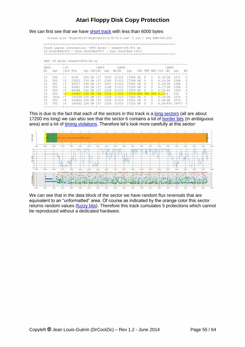
Atari Floppy Disk Copy Protection
Copyleft Jean Louis-Guérin (DrCoolZic) – Rev 1.2 - June 2014 Page 55 / 64
We can first see that we have short track with less than 6000 bytes
Stream file 'NightShift\NightShift(1-2)79.0.raw' 5 rot - Avg RPM=300.203
****************************************************************************
Track Layout Information: 5993 Bytes - length=199.971 ms
ID Good/Bad=9/0 - Data Good/Bad=8/1 - Sync Good/Bad =18/1
****************************************************************************
GAP1 60 bytes length=2034.68 us
-----------+------------------+-----------+---------------------------+------------
GAP2 |ID |GAP3 |DATA |GAP4
Bt Lgt |Sct Pos Lgt CRC|Bt Lgt BS|Bt Lgt CRC TMV BRD Clk |Bt Lgt BS
-----------+------------------+-----------+---------------------------+------------
15 500 |1 2535 234 OK |37 1235 0|515 17244 OK 0 0 4.19|38 1271 0
15 502 |2 23023 234 OK |37 1240 0|515 17248 OK 0 0 4.19|38 1268 0
15 501 |3 43517 234 OK |37 1237 0|515 17202 OK 0 0 4.18|38 1268 0
15 501 |4 63961 234 OK |37 1238 0|515 17183 OK 0 0 4.17|38 1268 0
15 502 |5 84388 234 OK |37 1238 0|515 17203 OK 0 0 4.18|40 1339 0
15 503 |6 104907 234 OK |38 1236 1|515 17018 BAD 982 946 4.13|4 125 0
54 1816 |7 125339 235 OK |37 1239 0|515 17260 OK 0 0 4.19|38 1274 0
15 503 |8 145854 234 OK |37 1235 0|515 17201 OK 0 0 4.18|38 1273 0
15 502 |9 166302 234 OK |37 1234 0|515 17226 OK 0 0 4.18|455 14973 0
-----------+------------------+-----------+---------------------------+------------
This is due to the fact that each of the sectors in this track is a long sectors (all are about 17200 ms long) we can also see that the sector 6 contains a lot of border bits (in ambiguous area) and a lot of timing violations. Therefore let’s look more carefully at this sector:
We can see that in the data block of the sector we have random flux reversals that are equivalent to an “unformatted” area. Of course as indicated by the orange color this sector returns random values (fuzzy bits). Therefore this track cumulates 5 protections which cannot be reproduced without a dedicated hardware.
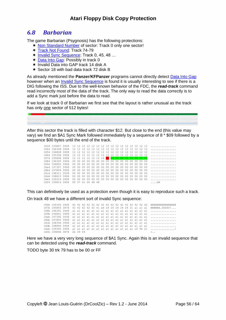
Atari Floppy Disk Copy Protection
Copyleft Jean Louis-Guérin (DrCoolZic) – Rev 1.2 - June 2014 Page 56 / 64
6.8 Barbarian The game Barbarian (Psygnosis) has the following protections: Non Standard Number of sector: Track 0 only one sector! Track Not Found: Track 74-79 Invalid Sync Sequence: Track 0, 45, 48 … Data Into Gap: Possibly in track 0 Invalid Data into GAP track 14 disk A Sector 18 with bad data track 72 disk B
As already mentioned the Panzer/KFPanzer programs cannot directly detect Data Into Gap however when an Invalid Sync Sequence is found it is usually interesting to see if there is a DIG following the ISS. Due to the well-known behavior of the FDC, the read-track command read incorrectly most of the data of the track. The only way to read the data correctly is to add a Sync mark just before the data to read.
If we look at track 0 of Barbarian we first see that the layout is rather unusual as the track has only one sector of 512 bytes!
After this sector the track is filled with character $12. But close to the end (this value may vary) we find an $A1 Sync Mark followed immediately by a sequence of 8 * $09 followed by a sequence $00 bytes until the end of the track.
1834 193807 3908 12 12 12 12 12 12 12 12 12 12 12 12 12 12 12 12 ................
1844 194308 3908 12 12 12 12 12 12 12 12 12 12 12 12 12 12 12 12 ................
1854 194808 3908 12 12 12 12 12 12 12 12 12 12 12 12 12 12 12 12 ................
1864 195308 3908 12 12 12 12 12 12 12 12 12 12 12 12 12 12 12 12 ................
1874 195808 3908 12 12 12 12 12 12 16 a1 09 09 09 09 09 09 09 09 ................
1884 196305 3908 00 00 00 00 00 00 00 00 00 00 00 00 00 00 00 00 ................
1894 196805 3908 00 00 00 00 00 00 00 00 00 00 00 00 00 00 00 00 ................
18a4 197307 3908 00 00 00 00 00 00 00 00 00 00 00 00 00 00 00 00 ................
18b4 197809 3908 00 00 00 00 00 00 00 00 00 00 00 00 00 00 00 00 ................
18c4 198311 3938 00 00 00 00 00 00 00 00 00 00 00 00 00 00 00 00 ................
18d4 198813 3908 00 00 00 00 00 00 00 00 00 00 00 00 00 00 00 00 ................
18e4 199314 3908 00 00 00 00 00 00 00 00 00 00 00 00 00 00 00 00 ................
18f4 199814 3908 00 07 0c 00 48 48 ....HH
This can definitively be used as a protection even though it is easy to reproduce such a track.
On track 48 we have a different sort of invalid Sync sequence:
186b 195393 3908 42 42 42 42 42 42 42 42 42 42 42 42 42 42 42 42 BBBBBBBBBBBBBBBB
187b 195893 3878 42 42 42 42 42 41 e4 24 24 24 24 24 21 a1 a1 a1 BBBBBA.$$$$$!...
188b 196391 3908 a1 a1 a1 a1 a1 a1 a1 a1 a1 a1 a1 a1 a1 a1 a1 a1 ................
189b 196891 3908 a1 a1 a1 a1 a1 a1 a1 a1 a1 a1 a1 a1 a1 a1 a1 a1 ................
18ab 197392 3938 a1 a1 a1 a1 a1 a1 a1 a1 a1 a1 a1 a1 a1 a1 a1 a1 ................
18bb 197893 3908 a1 a1 a1 a1 a1 a1 a1 a1 a1 a1 a1 a1 a1 a1 a1 a1 ................
18cb 198394 3908 a1 a1 a1 a1 a1 a1 a1 a1 a1 a1 a1 a1 a1 a1 a1 a1 ................
18db 198895 3908 a1 a1 a1 a1 a1 a1 a1 a1 a1 a1 a1 a1 a1 a1 a1 a1 ................
18eb 199395 3908 a1 a1 a1 a1 a1 a1 a1 a1 a1 a1 a1 a1 a1 c0 96 21 ...............!
18fb 199896 3878 2b 09 09 +..
Here we have a very very long sequence of $A1 Sync. Again this is an invalid sequence that can be detected using the read-track command.
TODO byte 30 trk 79 has to be 00 or FF
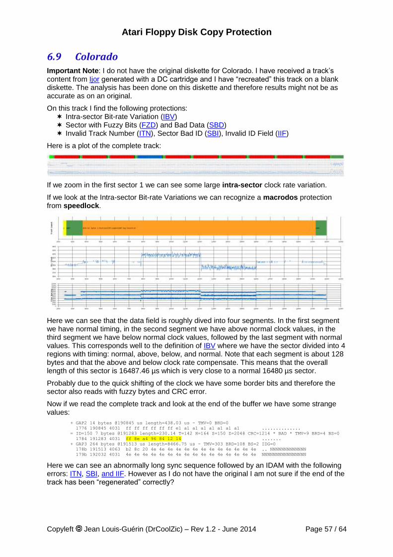
Atari Floppy Disk Copy Protection
Copyleft Jean Louis-Guérin (DrCoolZic) – Rev 1.2 - June 2014 Page 57 / 64
6.9 Colorado Important Note: I do not have the original diskette for Colorado. I have received a track’s content from Ijor generated with a DC cartridge and I have “recreated” this track on a blank diskette. The analysis has been done on this diskette and therefore results might not be as accurate as on an original.
On this track I find the following protections: Intra-sector Bit-rate Variation (IBV) Sector with Fuzzy Bits (FZD) and Bad Data (SBD) Invalid Track Number (ITN), Sector Bad ID (SBI), Invalid ID Field (IIF)
Here is a plot of the complete track:
If we zoom in the first sector 1 we can see some large intra-sector clock rate variation.
If we look at the Intra-sector Bit-rate Variations we can recognize a macrodos protection from speedlock.
Here we can see that the data field is roughly dived into four segments. In the first segment we have normal timing, in the second segment we have above normal clock values, in the third segment we have below normal clock values, followed by the last segment with normal values. This corresponds well to the definition of IBV where we have the sector divided into 4 regions with timing: normal, above, below, and normal. Note that each segment is about 128 bytes and that the above and below clock rate compensate. This means that the overall length of this sector is 16487.46 µs which is very close to a normal 16480 µs sector.
Probably due to the quick shifting of the clock we have some border bits and therefore the sector also reads with fuzzy bytes and CRC error.
Now if we read the complete track and look at the end of the buffer we have some strange values:
+ GAP2 14 bytes @190845 us length=438.03 us - TMV=0 BRD=0
1776 190845 4031 ff ff ff ff ff ff e1 a1 a1 a1 a1 a1 a1 a1 ..............
= ID=150 7 bytes @191283 length=230.14 T=142 H=164 S=150 Z=2048 CRC=1214 * BAD * TMV=9 BRD=4 BS=0
1784 191283 4031 ff 8e a4 96 84 12 14 .......
+ GAP3 264 bytes @191513 us length=8466.75 us - TMV=303 BRD=108 BS=2 IDG=0
178b 191513 4063 b2 8c 20 4e 4e 4e 4e 4e 4e 4e 4e 4e 4e 4e 4e 4e .. NNNNNNNNNNNNN
179b 192032 4031 4e 4e 4e 4e 4e 4e 4e 4e 4e 4e 4e 4e 4e 4e 4e 4e NNNNNNNNNNNNNNNN
Here we can see an abnormally long sync sequence followed by an IDAM with the following errors: ITN, SBI, and IIF. However as I do not have the original I am not sure if the end of the track has been “regenerated” correctly?
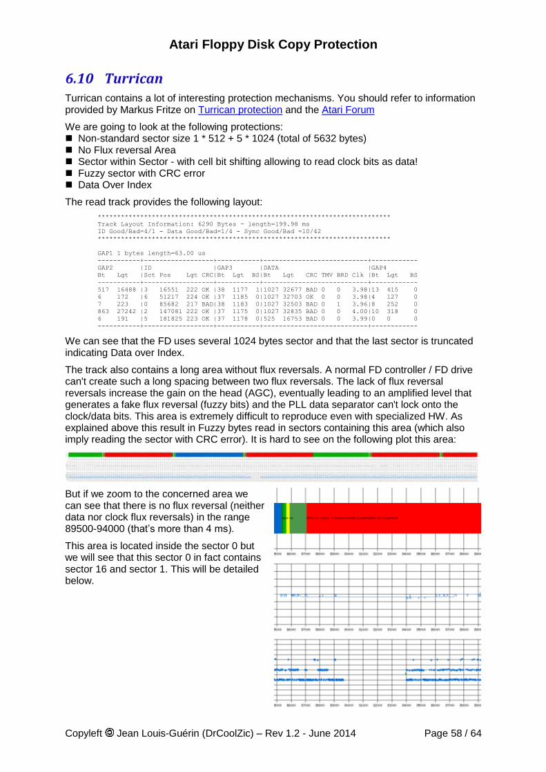
Atari Floppy Disk Copy Protection
Copyleft Jean Louis-Guérin (DrCoolZic) – Rev 1.2 - June 2014 Page 58 / 64
6.10 Turrican Turrican contains a lot of interesting protection mechanisms. You should refer to information provided by Markus Fritze on Turrican protection and the Atari Forum
We are going to look at the following protections: Non-standard sector size 1 * 512 + 5 * 1024 (total of 5632 bytes) No Flux reversal Area Sector within Sector - with cell bit shifting allowing to read clock bits as data! Fuzzy sector with CRC error Data Over Index
The read track provides the following layout:
****************************************************************************
Track Layout Information: 6290 Bytes - length=199.98 ms
ID Good/Bad=4/1 - Data Good/Bad=1/4 - Sync Good/Bad =10/42
****************************************************************************
GAP1 1 bytes length=63.00 us
-----------+------------------+-----------+---------------------------+------------
GAP2 |ID |GAP3 |DATA |GAP4
Bt Lgt |Sct Pos Lgt CRC|Bt Lgt BS|Bt Lgt CRC TMV BRD Clk |Bt Lgt BS
-----------+------------------+-----------+---------------------------+------------
517 16488 |3 16551 222 OK |38 1177 1|1027 32677 BAD 0 0 3.98|13 415 0
6 172 |6 51217 224 OK |37 1185 0|1027 32703 OK 0 0 3.98|4 127 0
7 223 |0 85682 217 BAD|38 1183 0|1027 32503 BAD 0 1 3.96|8 252 0
863 27242 |2 147081 222 OK |37 1175 0|1027 32835 BAD 0 0 4.00|10 318 0
6 191 |5 181825 223 OK |37 1178 0|525 16753 BAD 0 0 3.99|0 0 0
-----------+------------------+-----------+---------------------------+------------
We can see that the FD uses several 1024 bytes sector and that the last sector is truncated indicating Data over Index.
The track also contains a long area without flux reversals. A normal FD controller / FD drive can't create such a long spacing between two flux reversals. The lack of flux reversal reversals increase the gain on the head (AGC), eventually leading to an amplified level that generates a fake flux reversal (fuzzy bits) and the PLL data separator can't lock onto the clock/data bits. This area is extremely difficult to reproduce even with specialized HW. As explained above this result in Fuzzy bytes read in sectors containing this area (which also imply reading the sector with CRC error). It is hard to see on the following plot this area:
But if we zoom to the concerned area we can see that there is no flux reversal (neither data nor clock flux reversals) in the range 89500-94000 (that’s more than 4 ms).
This area is located inside the sector 0 but we will see that this sector 0 in fact contains sector 16 and sector 1. This will be detailed below.
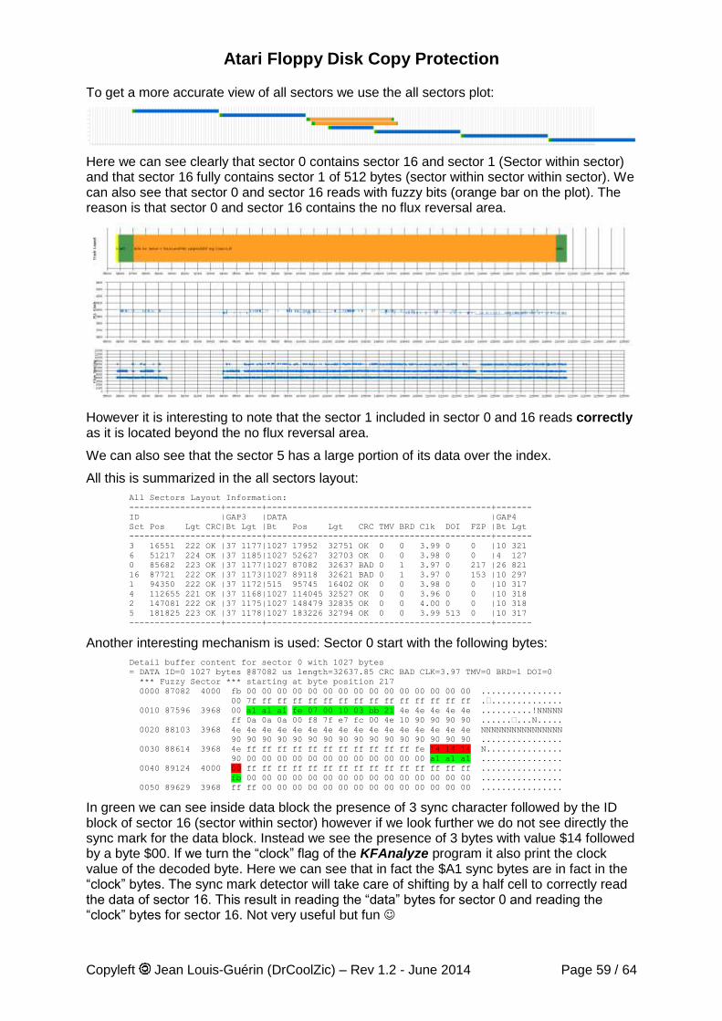
Atari Floppy Disk Copy Protection
Copyleft Jean Louis-Guérin (DrCoolZic) – Rev 1.2 - June 2014 Page 59 / 64
To get a more accurate view of all sectors we use the all sectors plot:
Here we can see clearly that sector 0 contains sector 16 and sector 1 (Sector within sector) and that sector 16 fully contains sector 1 of 512 bytes (sector within sector within sector). We can also see that sector 0 and sector 16 reads with fuzzy bits (orange bar on the plot). The reason is that sector 0 and sector 16 contains the no flux reversal area.
However it is interesting to note that the sector 1 included in sector 0 and 16 reads correctly as it is located beyond the no flux reversal area.
We can also see that the sector 5 has a large portion of its data over the index.
All this is summarized in the all sectors layout:
All Sectors Layout Information:
------------------+-------+--------------------------------------------+-------
ID |GAP3 |DATA |GAP4
Sct Pos Lgt CRC|Bt Lgt |Bt Pos Lgt CRC TMV BRD Clk DOI FZP |Bt Lgt
------------------+-------+--------------------------------------------+-------
3 16551 222 OK |37 1177|1027 17952 32751 OK 0 0 3.99 0 0 |10 321
6 51217 224 OK |37 1185|1027 52627 32703 OK 0 0 3.98 0 0 |4 127
0 85682 223 OK |37 1177|1027 87082 32637 BAD 0 1 3.97 0 217 |26 821
16 87721 222 OK |37 1173|1027 89118 32621 BAD 0 1 3.97 0 153 |10 297
1 94350 222 OK |37 1172|515 95745 16402 OK 0 0 3.98 0 0 |10 317
4 112655 221 OK |37 1168|1027 114045 32527 OK 0 0 3.96 0 0 |10 318
2 147081 222 OK |37 1175|1027 148479 32835 OK 0 0 4.00 0 0 |10 318
5 181825 223 OK |37 1178|1027 183226 32794 OK 0 0 3.99 513 0 |10 317
------------------+-------+--------------------------------------------+-------
Another interesting mechanism is used: Sector 0 start with the following bytes:
Detail buffer content for sector 0 with 1027 bytes
= DATA ID=0 1027 bytes @87082 us length=32637.85 CRC BAD CLK=3.97 TMV=0 BRD=1 DOI=0
*** Fuzzy Sector *** starting at byte position 217
0000 87082 4000 fb 00 00 00 00 00 00 00 00 00 00 00 00 00 00 00 ................
00 7f ff ff ff ff ff ff ff ff ff ff ff ff ff ff .•..............
0010 87596 3968 00 a1 a1 a1 fe 07 00 10 03 bb 21 4e 4e 4e 4e 4e ..........!NNNNN
ff 0a 0a 0a 00 f8 7f e7 fc 00 4e 10 90 90 90 90 ......•...N.....
0020 88103 3968 4e 4e 4e 4e 4e 4e 4e 4e 4e 4e 4e 4e 4e 4e 4e 4e NNNNNNNNNNNNNNNN
90 90 90 90 90 90 90 90 90 90 90 90 90 90 90 90 ................
0030 88614 3968 4e ff ff ff ff ff ff ff ff ff ff ff fe 14 14 14 N...............
90 00 00 00 00 00 00 00 00 00 00 00 00 a1 a1 a1 ................
0040 89124 4000 00 ff ff ff ff ff ff ff ff ff ff ff ff ff ff ff ................
fb 00 00 00 00 00 00 00 00 00 00 00 00 00 00 00 ................
0050 89629 3968 ff ff 00 00 00 00 00 00 00 00 00 00 00 00 00 00 ................
In green we can see inside data block the presence of 3 sync character followed by the ID block of sector 16 (sector within sector) however if we look further we do not see directly the sync mark for the data block. Instead we see the presence of 3 bytes with value $14 followed by a byte $00. If we turn the “clock” flag of the KFAnalyze program it also print the clock value of the decoded byte. Here we can see that in fact the $A1 sync bytes are in fact in the “clock” bytes. The sync mark detector will take care of shifting by a half cell to correctly read the data of sector 16. This result in reading the “data” bytes for sector 0 and reading the “clock” bytes for sector 16. Not very useful but fun
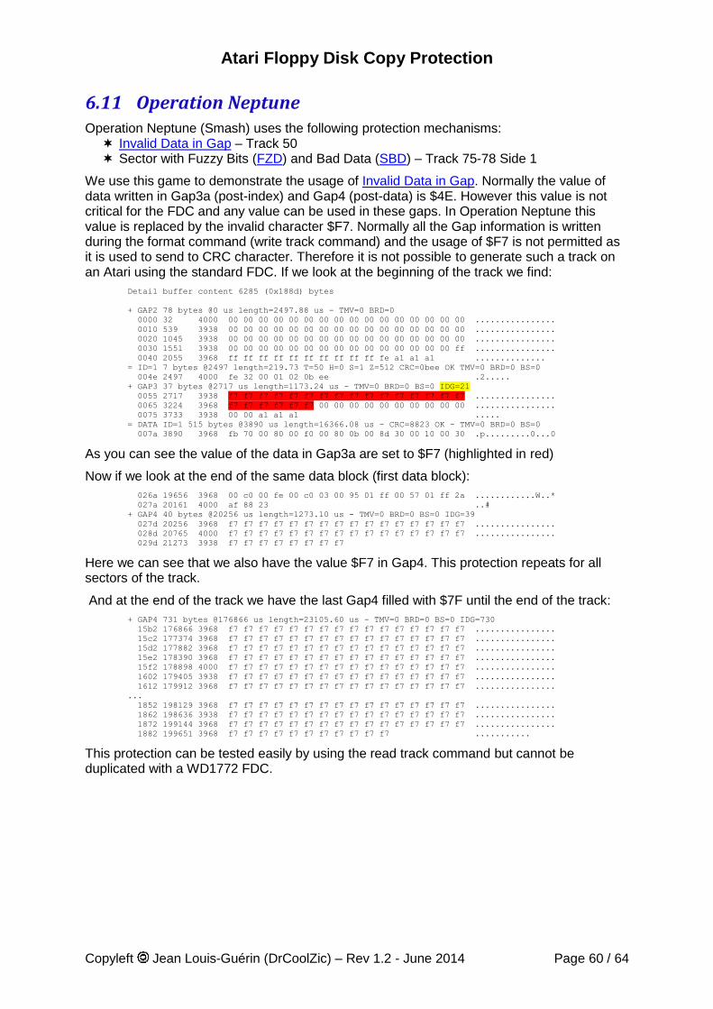
Atari Floppy Disk Copy Protection
Copyleft Jean Louis-Guérin (DrCoolZic) – Rev 1.2 - June 2014 Page 60 / 64
6.11 Operation Neptune Operation Neptune (Smash) uses the following protection mechanisms: Invalid Data in Gap – Track 50 Sector with Fuzzy Bits (FZD) and Bad Data (SBD) – Track 75-78 Side 1
We use this game to demonstrate the usage of Invalid Data in Gap. Normally the value of data written in Gap3a (post-index) and Gap4 (post-data) is $4E. However this value is not critical for the FDC and any value can be used in these gaps. In Operation Neptune this value is replaced by the invalid character $F7. Normally all the Gap information is written during the format command (write track command) and the usage of $F7 is not permitted as it is used to send to CRC character. Therefore it is not possible to generate such a track on an Atari using the standard FDC. If we look at the beginning of the track we find:
Detail buffer content 6285 (0x188d) bytes
+ GAP2 78 bytes @0 us length=2497.88 us - TMV=0 BRD=0
0000 32 4000 00 00 00 00 00 00 00 00 00 00 00 00 00 00 00 00 ................
0010 539 3938 00 00 00 00 00 00 00 00 00 00 00 00 00 00 00 00 ................
0020 1045 3938 00 00 00 00 00 00 00 00 00 00 00 00 00 00 00 00 ................
0030 1551 3938 00 00 00 00 00 00 00 00 00 00 00 00 00 00 00 ff ................
0040 2055 3968 ff ff ff ff ff ff ff ff ff ff fe a1 a1 a1 ..............
= ID=1 7 bytes @2497 length=219.73 T=50 H=0 S=1 Z=512 CRC=0bee OK TMV=0 BRD=0 BS=0
004e 2497 4000 fe 32 00 01 02 0b ee .2.....
+ GAP3 37 bytes @2717 us length=1173.24 us - TMV=0 BRD=0 BS=0 IDG=21
0055 2717 3938 f7 f7 f7 f7 f7 f7 f7 f7 f7 f7 f7 f7 f7 f7 f7 f7 ................
0065 3224 3968 f7 f7 f7 f7 f7 f7 00 00 00 00 00 00 00 00 00 00 ................
0075 3733 3938 00 00 a1 a1 a1 .....
= DATA ID=1 515 bytes @3890 us length=16366.08 us - CRC=8823 OK - TMV=0 BRD=0 BS=0
007a 3890 3968 fb 70 00 80 00 f0 00 80 0b 00 8d 30 00 10 00 30 .p.........0...0
As you can see the value of the data in Gap3a are set to $F7 (highlighted in red)
Now if we look at the end of the same data block (first data block):
026a 19656 3968 00 c0 00 fe 00 c0 03 00 95 01 ff 00 57 01 ff 2a ............W..*
027a 20161 4000 af 88 23 ..#
+ GAP4 40 bytes @20256 us length=1273.10 us - TMV=0 BRD=0 BS=0 IDG=39
027d 20256 3968 f7 f7 f7 f7 f7 f7 f7 f7 f7 f7 f7 f7 f7 f7 f7 f7 ................
028d 20765 4000 f7 f7 f7 f7 f7 f7 f7 f7 f7 f7 f7 f7 f7 f7 f7 f7 ................
029d 21273 3938 f7 f7 f7 f7 f7 f7 f7 f7
Here we can see that we also have the value $F7 in Gap4. This protection repeats for all sectors of the track.
And at the end of the track we have the last Gap4 filled with $7F until the end of the track:
+ GAP4 731 bytes @176866 us length=23105.60 us - TMV=0 BRD=0 BS=0 IDG=730
15b2 176866 3968 f7 f7 f7 f7 f7 f7 f7 f7 f7 f7 f7 f7 f7 f7 f7 f7 ................
15c2 177374 3968 f7 f7 f7 f7 f7 f7 f7 f7 f7 f7 f7 f7 f7 f7 f7 f7 ................
15d2 177882 3968 f7 f7 f7 f7 f7 f7 f7 f7 f7 f7 f7 f7 f7 f7 f7 f7 ................
15e2 178390 3968 f7 f7 f7 f7 f7 f7 f7 f7 f7 f7 f7 f7 f7 f7 f7 f7 ................
15f2 178898 4000 f7 f7 f7 f7 f7 f7 f7 f7 f7 f7 f7 f7 f7 f7 f7 f7 ................
1602 179405 3938 f7 f7 f7 f7 f7 f7 f7 f7 f7 f7 f7 f7 f7 f7 f7 f7 ................
1612 179912 3968 f7 f7 f7 f7 f7 f7 f7 f7 f7 f7 f7 f7 f7 f7 f7 f7 ................
...
1852 198129 3968 f7 f7 f7 f7 f7 f7 f7 f7 f7 f7 f7 f7 f7 f7 f7 f7 ................
1862 198636 3938 f7 f7 f7 f7 f7 f7 f7 f7 f7 f7 f7 f7 f7 f7 f7 f7 ................
1872 199144 3968 f7 f7 f7 f7 f7 f7 f7 f7 f7 f7 f7 f7 f7 f7 f7 f7 ................
1882 199651 3968 f7 f7 f7 f7 f7 f7 f7 f7 f7 f7 f7 ...........
This protection can be tested easily by using the read track command but cannot be duplicated with a WD1772 FDC.
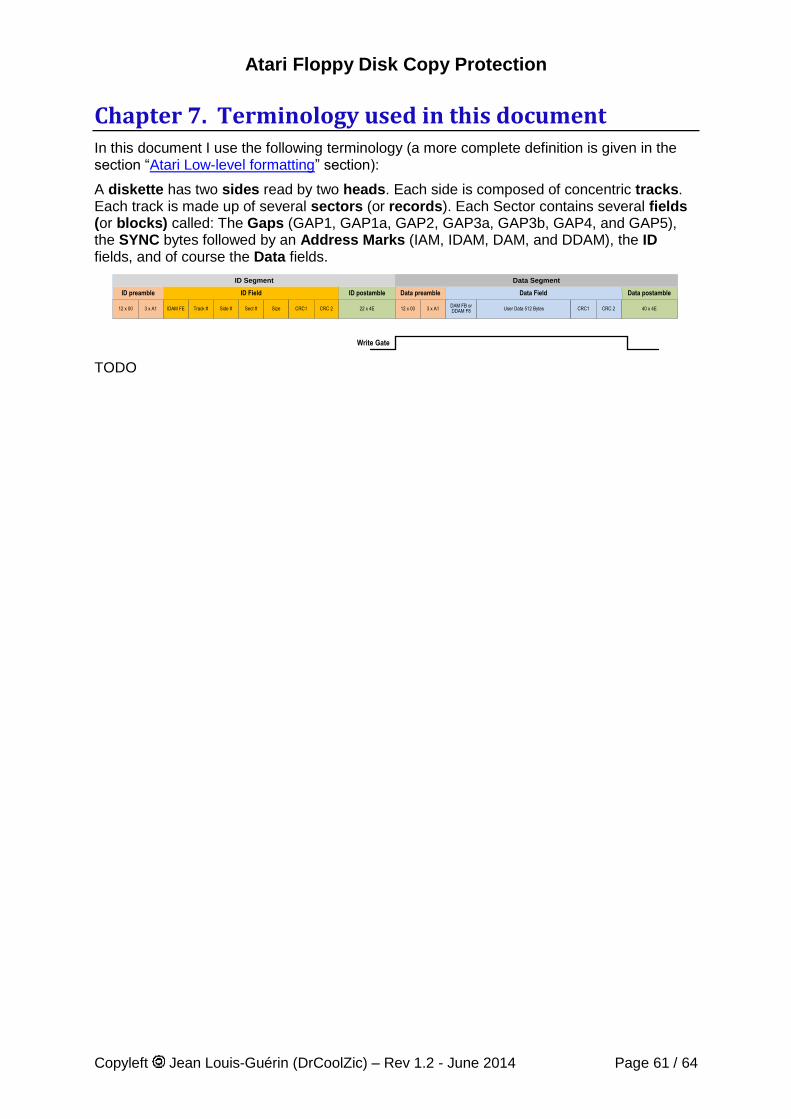
Atari Floppy Disk Copy Protection
Copyleft Jean Louis-Guérin (DrCoolZic) – Rev 1.2 - June 2014 Page 61 / 64
Chapter 7. Terminology used in this document In this document I use the following terminology (a more complete definition is given in the section “Atari Low-level formatting” section):
A diskette has two sides read by two heads. Each side is composed of concentric tracks. Each track is made up of several sectors (or records). Each Sector contains several fields (or blocks) called: The Gaps (GAP1, GAP1a, GAP2, GAP3a, GAP3b, GAP4, and GAP5), the SYNC bytes followed by an Address Marks (IAM, IDAM, DAM, and DDAM), the ID fields, and of course the Data fields.
22 x 4E 40 x 4E12 x 00 3 x A1DAM FB orDDAM F8 User Data 512 Bytes CRC1 CRC 212 x 00 3 x A1IDAM FE Track # Side # Sect # Size CRC1 CRC 2
Write Gate
ID Segment
ID Field ID postamble Data preamble Data Field Data postambleID preamble
Data Segment
TODO
Atari Floppy Disk Copy Protection
Copyleft Jean Louis-Guérin (DrCoolZic) – Rev 1.2 - June 2014 Page 62 / 64
Chapter 8. References
8.1 Documents / Articles Article on protection "copy me I want to travel" from Claus Brod the expert who wrote the
book Scheibenkleiste covering all sort of interesting details about floppy disks, hard disks, RAM disks, CD-ROMs and other mass storage devices for the Atari (Claus web site).
Probing the FDC: Learn the Secrets of your Floppy - By David Small Atari Protected Disk Image Format & Atari Protected Disk Image Format Floppy disk formatHow can I copy my copy-protected Atari software An interview with Rob Northen Dungeon Master Copy Protection Disk Backup Programs: Do they really work Teac & Citizen Micro Floppy Disk Drive Specification Floppy from HP How to HD install Pacland (MFM format) using WHDLoad Commodore C1581-handler S100-Manuals - Disks and Disk Drives Wipe Swap File SpinRight Technical note
8.2 Forums Threads Looking for Rob Northen originals Rob Northern Code Found Weak Bits, Bit-rate var., data under index: Copy Protection Questions Regarding STT Images Protected disk images project & CAPS Ideas about ST floppy image make program for PC PASTI Project Copy II ST Looking for AntiBitos 1.4 by Illegal Most memorable Hack/crack Protected Disk Image Project Seeking Beta Tester Ideas about ST floppy image make program for PC Looking for DMA file under interrupt Mega STE Specifics Copy Protected Disks Gcopy DIM file ST Protection routines Putting a second internal floppy drive in the STF RamDisk and ATARI-ST Disk IO X-out original protected Copy Protected Disk – Turrican NFA Protection (IFW / mr.Vince)
Atari Floppy Disk Copy Protection
Copyleft Jean Louis-Guérin (DrCoolZic) – Rev 1.2 - June 2014 Page 63 / 64
8.3 Related Patents You may want to look at the following patents that describe some protection mechanisms: Copy Protection for computer Disc 4,849,836 Computer Program protection method 4,462,078 Hardware key-on-disc for copy protecting magnetic storage data 4,577,289 Copy protecting system for software protection 4,584,641 Techniques for preventing unauthorized copying of information recorded on a recording
medium and a protected recording medium 4,734,796 Copy protection disc format controller 5,432,647 Data Input Circuit with Digital Phase Lock Loop
8.4 Web Sites Atari ST FD (Hardware view) Atari ST FD (Software view) Atari FD Protection/Preservation Atari ST Copy Protections (Markus Fritze) Protections sur Atari ST/Amiga PASTI Project Software Preservation Society KryoFlux Products & Services Limited C64 Preservation Project (Commodore) Atari Disk Image FAQ Tim Mann's TRS-80 Pages The .ADF (Amiga Disk File) format FAQ Introduction to Magnetic Recording Funny presentation about perpendicular magnetic recording !!! Individual Computer Support The Central Point Option Board SpinRite's Defect Detection Magnetodynamics The Gentle art of Protection The XCOMP/2 home page LIBDSK library for accessing discs and disc image files WinUAE Amiga Emulator
8.5 FDC & Related Information Western Digital Corporation 5.25" WD1770/1772 Floppy Disk Controller/Formatter 8272 SINGLE/DOUBLE DENSITY FLOPPY DISK CONTROLLER Intel 82077AA FDC Datasheet Commodore C1581 - WD1770 FLOPPY DISK CONTROLLER PC87310 (SuperI/OTM) Dual UART with Floppy Disk Controller and Parallel Port Hard Disk Data Encoding / Decoding. Cyclic Redundancy Check, CRC16-CCITT, The Great CRC Mystery Terry Ritter Atari ST – Floppy Disk Programming – Jean Louis-Guérin WD1772 Floppy Disk Formatter/Controller - Western Digital Corporation
Atari Floppy Disk Copy Protection
Copyleft Jean Louis-Guérin (DrCoolZic) – Rev 1.2 - June 2014 Page 64 / 64
Chapter 9. Document history V1.2 Lots of information added, regrouping of related protections, new examples, etc.
Most significant is Unformatted Tracks, No Sector Data Track, Partially unformatted track, Fuzzy Data Track, No Flux Area on Disk, Unformatted Diskette / Track / Sector …
V1.0 Added information on low level format, particularly about the write splice. Added description about KFPanzer and KFAnalyze. Now the analysis of games uses the output from KFAnalyze and especially the nice plots. Added the Short/Long Track and No Flux reversal Area protections. Remove documentation of Analyze program. Added more analysis of games (Turrican and others). New information about games protection based on new KFPanzer capabilities. Added more links to new sites. Added reference to the new KryoFlux board and related - After 5 years of development I consider the document mature enough to go to version 1.0 - November 2011
V0.9 Clean-up text based on feedback. Modified documentation to reflect the usage of the new Panzer (Protection ANalyZER) program. Added ID Fuzzy Bits, Invalid Data in Gap, and Non Standard DAM Protection. Added a section on Preservation for each of the protections. Added description for Barbarian, Operation Neptune Game. Work with Gothmog (Christophe Fontanel) on getting more accurate information on Dungeon Master fuzzy bits protection – September 2010
V0.8 Added taxonomy for the different protection categories. Rewrote of large portion of the explanations about fuzzy bits. Added 5 new protections: Invalid ID Field, Non Standard IDAM, Sector over Index pulse, Missing Track and Sector within Sector. Added description for several games (Theme Park Mystery, Computer Hits Volume 2, Kick Off 2, Colorado). Better documented Intra-sector Bit Variation with reference to Colorado. For the first time lots of diskettes (over 50) have been tested and references for them have been entered in the document. And again lots of clean-up – October 2007
V0.7 several modifications based on feedback from Ijor and Obo. Added a new section on weak bits based on US patent and a section on Invalid character during format. Plus lots of miscellaneous cleanup. – January 2007
V0.6 Modifications based on feedback from Ijor, I have added one section about Double Density diskette format, the Invalid sector number protection, and the intra-sector variable bit rate protection – December 2006
V0.5 Incorporated feedback from Gothmog about the DM protection patent, added a section with several US patent about protection, modified the section on fuzzy bits, modified the fuzzy bit detection in WD1772 DPLL – December 2006
V0.4 Complete documentation cleanup and links verification - November 2006. V0.3 Major Revision: Merged several related sector protections, modified extensively the
description of several protections, added section on example of protections, added analyze program short presentation, added DPLL presentation, and added new protections: PAT and NAT. - October 2006.
V0.2 Minor correction based on feedback - June 2006. V0.1 Initial writing - May 2006.