Embed Size (px)
Citation preview
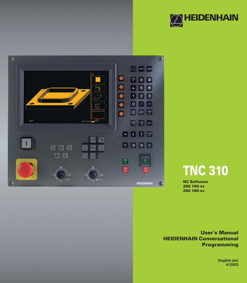
User's ManualHEIDENHAIN Conversational
Programming
English (en)4/2003
TNC 310NC Software286 140-xx286 160-xx
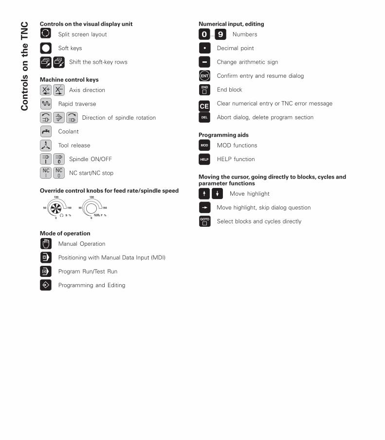
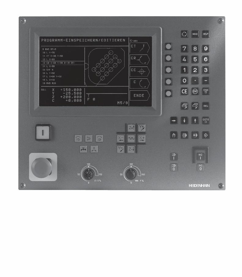
Controls on the visual display unit
Split screen layout
Soft keys
Shift the soft-key rows
Machine control keys
Axis direction
Rapid traverse
Direction of spindle rotation
Coolant
Tool release
Spindle ON/OFF
NC start/NC stop
Override control knobs for feed rate/spindle speed
Mode of operation
Manual Operation
Positioning with Manual Data Input (MDI)
Program Run/Test Run
Programming and Editing
Numerical input, editing
... Numbers
Decimal point
Change arithmetic sign
Confirm entry and resume dialog
End block
Clear numerical entry or TNC error message
Abort dialog, delete program section
Programming aids
MOD functions
HELP function
Moving the cursor, going directly to blocks, cycles andparameter functions
Move highlight
Move highlight, skip dialog question
Select blocks and cycles directly
Co
ntr
ols
on
th
e T
NC
150
0
50
100
S %
150
0
50
100
F %

Co
nte
nts
IHEIDENHAIN TNC 310
TNC Models, Software andFeatures
This manual describes functions and features provided bythe TNCs with the following NC software numbers.
TNC Model NC Software No.
TNC 310 286 140-xxTNC 310 M 286 160-xx
The machine tool builder adapts the useable features of theTNC to his machine by setting machine parameters. Someof the functions described in this manual may not beamong the features provided by the TNC on your machinetool.
TNC functions that may not be available on your machineinclude:
■ Probing function for the 3-D touch probe
■ Rigid tapping cycle
■ Boring cycle
■ Back boring cycle
Please contact your machine tool builder to become familiarwith the individual implementation of the control on yourmachine.
Many machine manufacturers, as well as HEIDENHAIN,offer programming courses for the TNCs. We recommendthese courses as an effective way of improving yourprogramming skill and sharing information and ideas withother TNC users.
Location of useThe TNC complies with the limits for a Class A device inaccordance with the specifications in EN 55022, and isintended for use primarily in industrially-zoned areas.

Co
nte
nts
IIIHEIDENHAIN TNC 310
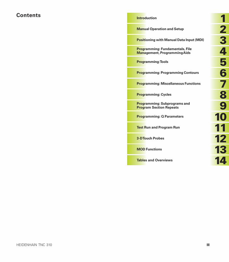
Introduction
Manual Operation and Setup
Programming: Tools
�Contents
�������
��������
Programming: Fundamentals, FileManagement, Programming Aids
Positioning with Manual Data Input (MDI)
Programming: Programming Contours
Programming: Miscellaneous Functions
Programming: Cycles
Programming: Subprograms andProgram Section Repeats
Test Run and Program Run
3-D Touch Probes
MOD Functions
Tables and Overviews
�Programming: Q Parameters
Co
nte
nts
ContentsIV
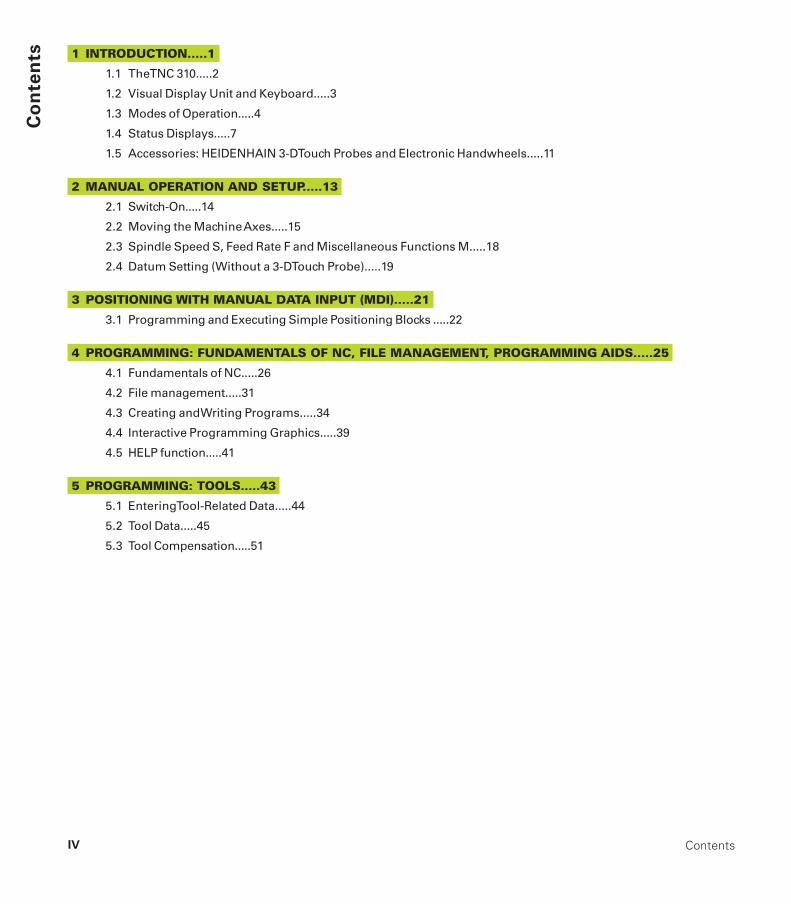
1 INTRODUCTION.....1
1.1 The TNC 310.....2
1.2 Visual Display Unit and Keyboard.....3
1.3 Modes of Operation.....4
1.4 Status Displays.....7
1.5 Accessories: HEIDENHAIN 3-D Touch Probes and Electronic Handwheels.....11
2 MANUAL OPERATION AND SETUP.....13
2.1 Switch-On.....14
2.2 Moving the Machine Axes.....15
2.3 Spindle Speed S, Feed Rate F and Miscellaneous Functions M.....18
2.4 Datum Setting (Without a 3-D Touch Probe).....19
3 POSITIONING WITH MANUAL DATA INPUT (MDI).....21
3.1 Programming and Executing Simple Positioning Blocks .....22
4 PROGRAMMING: FUNDAMENTALS OF NC, FILE MANAGEMENT, PROGRAMMING AIDS.....25
4.1 Fundamentals of NC.....26
4.2 File management.....31
4.3 Creating and Writing Programs.....34
4.4 Interactive Programming Graphics.....39
4.5 HELP function.....41
5 PROGRAMMING: TOOLS.....43
5.1 Entering Tool-Related Data.....44
5.2 Tool Data.....45
5.3 Tool Compensation.....51
Co
nte
nts
VHEIDENHAIN TNC 310
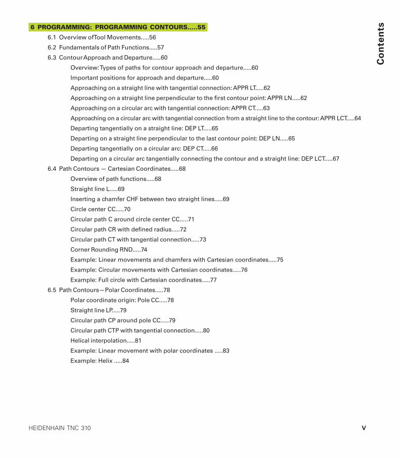
6 PROGRAMMING: PROGRAMMING CONTOURS.....55
6.1 Overview of Tool Movements.....56
6.2 Fundamentals of Path Functions.....57
6.3 Contour Approach and Departure.....60
Overview: Types of paths for contour approach and departure.....60
Important positions for approach and departure.....60
Approaching on a straight line with tangential connection: APPR LT.....62
Approaching on a straight line perpendicular to the first contour point: APPR LN.....62
Approaching on a circular arc with tangential connection: APPR CT.....63
Approaching on a circular arc with tangential connection from a straight line to the contour: APPR LCT.....64
Departing tangentially on a straight line: DEP LT.....65
Departing on a straight line perpendicular to the last contour point: DEP LN.....65
Departing tangentially on a circular arc: DEP CT.....66
Departing on a circular arc tangentially connecting the contour and a straight line: DEP LCT.....67
6.4 Path Contours — Cartesian Coordinates.....68
Overview of path functions.....68
Straight line L.....69
Inserting a chamfer CHF between two straight lines.....69
Circle center CC.....70
Circular path C around circle center CC.....71
Circular path CR with defined radius.....72
Circular path CT with tangential connection.....73
Corner Rounding RND.....74
Example: Linear movements and chamfers with Cartesian coordinates.....75
Example: Circular movements with Cartesian coordinates.....76
Example: Full circle with Cartesian coordinates.....77
6.5 Path Contours—Polar Coordinates.....78
Polar coordinate origin: Pole CC.....78
Straight line LP.....79
Circular path CP around pole CC.....79
Circular path CTP with tangential connection.....80
Helical interpolation.....81
Example: Linear movement with polar coordinates .....83
Example: Helix .....84
Co
nte
nts
ContentsVI
7 PROGRAMMING: MISCELLANEOUS FUNCTIONS.....85
7.1 Entering Miscellaneous Functions M and STOP.....86
7.2 Miscellaneous Functions for Program Run Control, Spindle and Coolant.....87
7.3 Miscellaneous Functions for Coordinate Data.....87
7.4 Miscellaneous Functions for Contouring Behavior.....89
7.5 Miscellaneous Function for Rotary Axes.....92
8 PROGRAMMING: CYCLES.....93
8.1 General Overview of Cycles.....94
8.2 Drilling Cycles.....96
PECKING (Cycle 1).....96
DRILLING (Cycle 200).....98
REAMING (Cycle 201).....99
BORING (Cycle 202).....100
UNIVERSAL DRILLING (Cycle 203).....101
BACK BORING (Cycle 204).....103
TAPPING with a floating tap holder (Cycle 2).....105
RIGID TAPPING (Cycle 17).....106
Example: Drilling cycles.....107
Example: Drilling cycles .....108
8.3 Cycles for Milling Pockets, Studs and Slots.....109
POCKET MILLING (Cycle 4).....110
POCKET FINISHING (Cycle 212).....111
STUD FINISHING (Cycle 213).....113
CIRCULAR POCKET MILLING (Cycle 5).....114
CIRCULAR POCKET FINISHING (Cycle 214).....116
CIRCULAR STUD FINISHING (Cycle 215) .....117
SLOT MILLING (Cycle 3).....119
SLOT with reciprocating plunge-cut (Cycle 210).....120
CIRCULAR SLOT with reciprocating plunge-cut (Cycle 211) .....122
Example: Milling pockets, studs and slots.....124
Co
nte
nts
VIIHEIDENHAIN TNC 310
8.4 Cycles for Machining Hole Patterns.....126
CIRCULAR PATTERN (Cycle 220).....127
LINEAR PATTERN (Cycle 221) .....128
Example: Circular hole patterns.....130
8.5 Cycles for multipass milling.....132
MULTIPASS MILLING (Cycle 230).....132
RULED SURFACE (Cycle 231).....134
Example: Multipass milling.....136
8.6 Coordinate Transformation Cycles .....137
DATUM SHIFT (Cycle 7).....138
DATUM SHIFT with datum tables (Cycle 7).....138
MIRROR IMAGE (Cycle 8).....140
ROTATION (Cycle 10).....141
SCALING FACTOR (Cycle 11) .....142
Example: Coordinate transformation cycles.....143
8.7 Special Cycles .....145
DWELL TIME (Cycle 9) .....145
PROGRAM CALL (Cycle 12).....145
ORIENTED SPINDLE STOP (Cycle 13) .....146
9 PROGRAMMING: SUBPROGRAMS AND PROGRAM SECTION REPEATS.....147
9.1 Labeling Subprograms and Program Section Repeats.....148
9.2 Subprograms.....148
9.3 Program Section Repeats.....149
9.4 Nesting.....151
Subprogram within a subprogram .....151
Repeating program section repeats.....152
Repeating a subprogram.....153
Example: Milling a contour in several infeeds .....154
Example: Groups of holes .....155
Example: Groups of holes with several tools .....156
Co
nte
nts
ContentsVIII
10 PROGRAMMING: Q PARAMETERS.....159
10.1 Principle and Overview.....160
10.2 Part Families — Q Parameters in Place of Numerical Values.....161
10.3 Describing Contours through Mathematical Operations.....162
10.4 Trigonometric Functions .....164
10.5 If-Then Decisions with Q Parameters .....165
10.6 Checking and Changing Q Parameters .....166
10.7 Additional Functions .....167
10.8 Entering Formulas Directly.....173
10.9 Preassigned Q Parameters.....176
10.10 Programming Examples.....178
Example: Ellipse.....178
Example: Concave cylinder machined with spherical cutter .....180
Example: Convex sphere machined with end mill .....182
11 TEST RUN AND PROGRAM RUN.....185
11.1 Graphics.....186
11.2 Test run.....190
11.3 Program Run.....192
11.4 Blockwise Transfer: Running Longer Programs.....199
11.5 Optional Program Run Interruption.....200
12 3-D TOUCH PROBES.....201
12.1 Touch Probe Cycles in the Manual Operation Mode.....202
Calibrating a touch trigger probe.....203
Compensating workpiece misalignment.....204
12.2 Setting the Datum with a 3-D Touch Probe.....205
12.3 Measuring Workpieces with a 3-D Touch Probe.....208
Co
nte
nts
IXHEIDENHAIN TNC 310
13 MOD FUNCTIONS.....211
13.1 Selecting, Changing and Exiting the MOD Functions.....212
13.2 System Information.....212
13.3 Entering the Code Number.....213
13.4 Setting the Data Interface.....213
13.5 Machine-Specific User Parameters.....216
13.6 Position Display Types.....216
13.7 Unit of Measurement.....216
13.8 Axis Traverse Limits .....217
13.9 Running the HELP File.....218
14 TABLES AND OVERVIEWS.....219
14.1 General User Parameters.....220
Input possibilities for machine parameters.....220
Selecting general user parameters.....220
External data transfer.....221
3-D Touch Probes.....222
TNC displays, TNC editor.....222
Machining and program run.....224
Electronic handwheels.....225
14.2 Pin Layout and Connecting Cable for the Data Interface.....226
RS-232-C/V.24 Interface .....226
14.3 Technical Information.....227
TNC features.....227
Programmable functions.....228
TNC Specifications.....228
14.4 TNC Error Messages.....229
TNC error messages during programming.....229
TNC error messages during test run and program run.....229
14.5 Exchanging the Buffer Battery.....232
Introduction
1
2
1.1 The TNC 310
HEIDENHAIN TNC controls are shop-floor programmablecontouring controls for milling, drilling and boring machines.
You can program conventional milling, drilling and boring operationsright at the machine with the easily understandable interactiveconversational guidance. The TNC 310 can control up to 4 axes.Instead of the fourth axis, you can also change the angular positionof the spindle under program control.
Keyboard and screen layout are clearly arranged in a such way thatthe functions are fast and easy to use.
Programming: HEIDENHAIN conversational formatHEIDENHAIN conversational programming is an especially easymethod of writing programs. Interactive graphics illustrate theindividual machining steps for programming the contour. Workpiecemachining can be graphically simulated during test run.
You can enter a program while the control is running another.
CompatibilityThe TNC can execute all part programs that were written onHEIDENHAIN controls TNC 150 B and later.
In addition, the TNC can also run programs with functions thatcannot be programmed directly on the TNC 310 itself, such as:
■ FK free contour programming
■ Contour cycles
■ ISO programs
■ Program call with PGM CALL
1.1
Th
e T
NC
310
1 Introduction
3HEIDENHAIN TNC 310
1.2 Visual Display Unit and Keyboard
Visual display unit
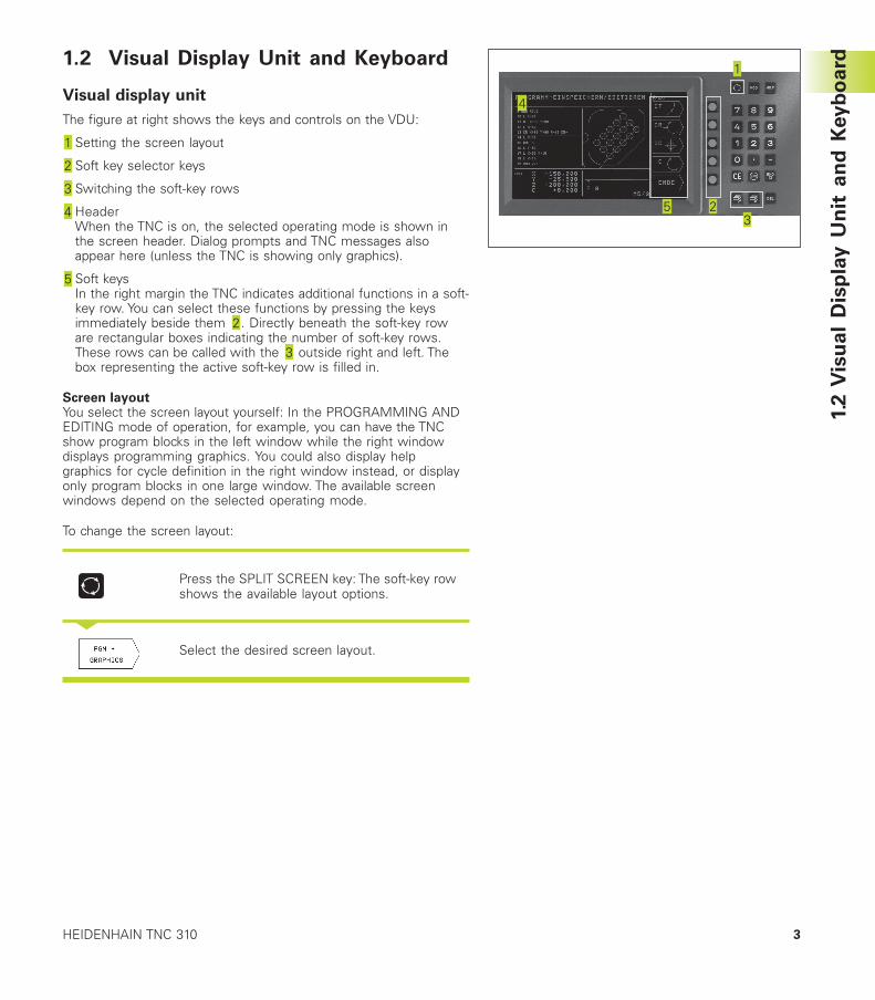
The figure at right shows the keys and controls on the VDU:
Setting the screen layout
Soft key selector keys
Switching the soft-key rows
HeaderWhen the TNC is on, the selected operating mode is shown inthe screen header. Dialog prompts and TNC messages alsoappear here (unless the TNC is showing only graphics).
Soft keysIn the right margin the TNC indicates additional functions in a soft-key row. You can select these functions by pressing the keysimmediately beside them . Directly beneath the soft-key roware rectangular boxes indicating the number of soft-key rows.These rows can be called with the outside right and left. Thebox representing the active soft-key row is filled in.
Screen layoutYou select the screen layout yourself: In the PROGRAMMING ANDEDITING mode of operation, for example, you can have the TNCshow program blocks in the left window while the right windowdisplays programming graphics. You could also display helpgraphics for cycle definition in the right window instead, or displayonly program blocks in one large window. The available screenwindows depend on the selected operating mode.
To change the screen layout:
Press the SPLIT SCREEN key: The soft-key rowshows the available layout options.
<
Select the desired screen layout.
1.2
Vis
ua
l D
isp
lay
Un
it a
nd
Key
bo
ard

4
1.3
Mo
des o
f O
pera
tio
n
1 Introduction
Keyboard
The figure at right shows the keys of the keyboard groupedaccording to their functions:
MOD function,HELP function
Numerical input
Dialog buttons
Arrow keys and GOTO jump command
Modes of Operation
Machine control buttons
Override control knobs for feed rate/spindle speed
The functions of the individual keys are described in the foldout ofthe front cover. The exact functioning of the machine controlbuttons, e.g. NC START, is described in more detail in your MachineManual.
1.3 Modes of Operation
The TNC offers the following modes of operation for the variousfunctions and working steps that you need to machine a workpiece:
Manual Operation and Electronic Handwheel
The Manual Operation mode is required for setting up the machinetool. In this operating mode, you can position the machine axesmanually or by increments. Datums can be set by the usualscratching method or by using the TS 220 triggering touch probe.The TNC also supports the manual traverse of the machine axesusing a HR electronic handwheel.
Soft keys for selecting the screen layout
Screen windows Soft key
Positions
Left: positions, right: generalprogram information
Left: positions, right: positions andCoordinates
Screen windows Soft key
Left: positions, right:information ontools
Left: positions, right:coordinatetransformations
5HEIDENHAIN TNC 310
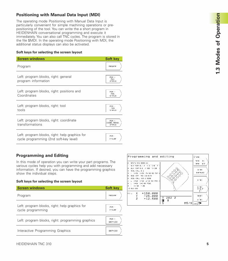
Positioning with Manual Data Input (MDI)
The operating mode Positioning with Manual Data Input isparticularly convenient for simple machining operations or pre-positioning of the tool. You can write the a short program inHEIDENHAIN conversational programming and execute itimmediately. You can also call TNC cycles. The program is stored inthe file $MDI. In the operating mode Positioning with MDI, theadditional status displays can also be activated.
Soft keys for selecting the screen layout
Screen windows Soft key
Program
Left: program blocks, right: generalprogram information
Left: program blocks, right: positions andCoordinates
Left: program blocks, right: tooltools
Left: program blocks, right: coordinatetransformations
Left: program blocks, right: help graphics forcycle programming (2nd soft-key level)
Programming and Editing
In this mode of operation you can write your part programs. Thevarious cycles help you with programming and add necessaryinformation. If desired, you can have the programming graphicsshow the individual steps.
Soft keys for selecting the screen layout
Screen windows Soft key
Program
Left: program blocks, right: help graphics forcycle programming
Left: program blocks, right: programming graphics
Interactive Programming Graphics
1.3
Mo
des o
f O
pera
tio
n
6
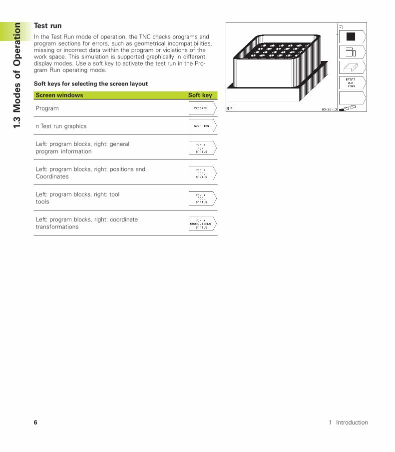
Test run
In the Test Run mode of operation, the TNC checks programs andprogram sections for errors, such as geometrical incompatibilities,missing or incorrect data within the program or violations of thework space. This simulation is supported graphically in differentdisplay modes. Use a soft key to activate the test run in the Pro-gram Run operating mode.
Soft keys for selecting the screen layout
Screen windows Soft key
Program
n Test run graphics
Left: program blocks, right: generalprogram information
Left: program blocks, right: positions andCoordinates
Left: program blocks, right: tooltools
Left: program blocks, right: coordinatetransformations
1.3
Mo
des o
f O
pera
tio
n
1 Introduction
7HEIDENHAIN TNC 310
1.4
Sta
tus D
isp
lay
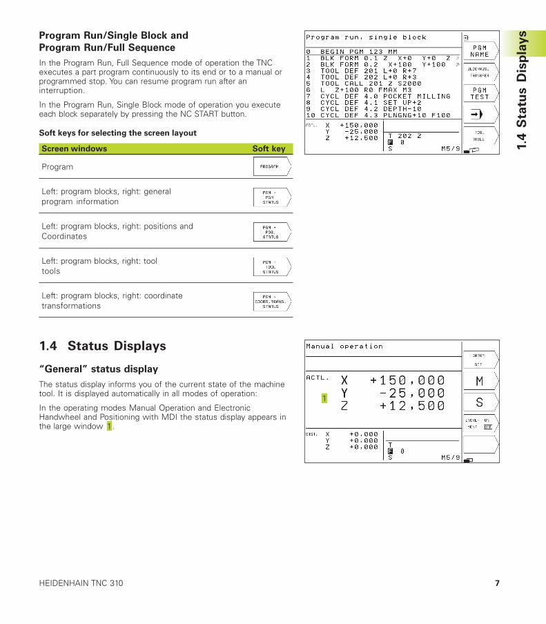
sProgram Run/Single Block and
Program Run/Full Sequence
In the Program Run, Full Sequence mode of operation the TNCexecutes a part program continuously to its end or to a manual orprogrammed stop. You can resume program run after aninterruption.
In the Program Run, Single Block mode of operation you executeeach block separately by pressing the NC START button.
Soft keys for selecting the screen layout
Screen windows Soft key
Program
Left: program blocks, right: generalprogram information
Left: program blocks, right: positions andCoordinates
Left: program blocks, right: tooltools
Left: program blocks, right: coordinatetransformations
1.4 Status Displays
“General” status display
The status display informs you of the current state of the machinetool. It is displayed automatically in all modes of operation:
In the operating modes Manual Operation and ElectronicHandwheel and Positioning with MDI the status display appears inthe large window .
8 1 Introduction
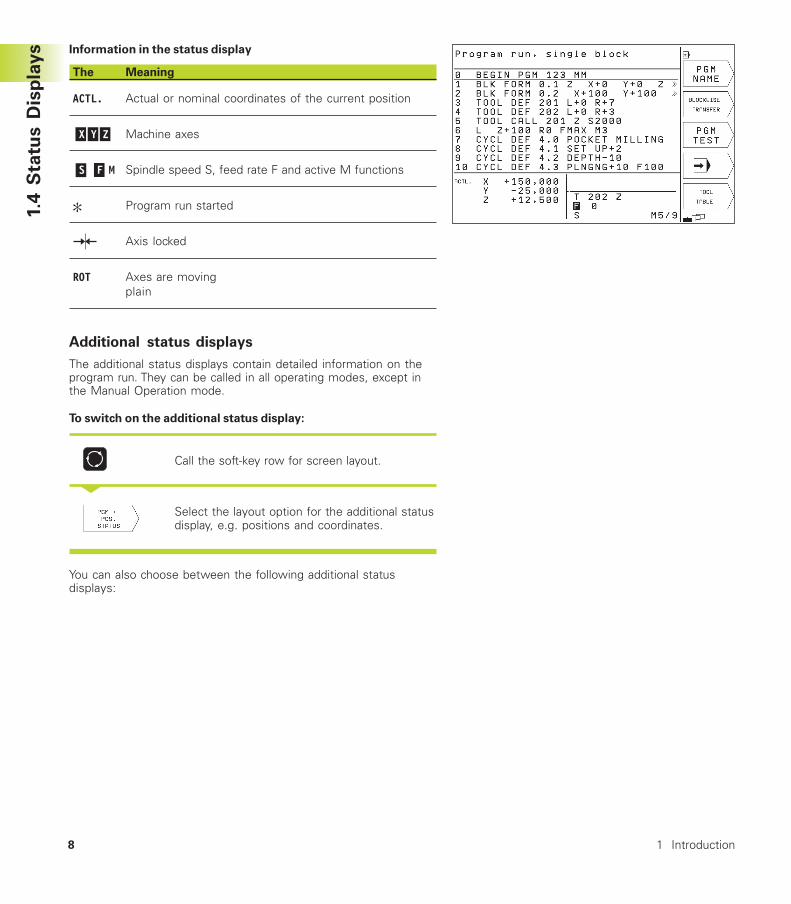
Information in the status display
The Meaning
ACTL. Actual or nominal coordinates of the current position
X Y Z Machine axes
S F M Spindle speed S, feed rate F and active M functions
Program run started
Axis locked
ROT Axes are movingplain
Additional status displays
The additional status displays contain detailed information on theprogram run. They can be called in all operating modes, except inthe Manual Operation mode.
To switch on the additional status display:
Call the soft-key row for screen layout.
<
Select the layout option for the additional statusdisplay, e.g. positions and coordinates.
You can also choose between the following additional statusdisplays:
1.4
Sta
tus D
isp
lay
s

9HEIDENHAIN TNC 310
General program information
Name of main program / Active block number
Program called via Cycle 12
Active machining cycle
Circle center CC (pole)
Dwell time counter
Number of the active subprogram or active program sectionrepeats/Counter for current program section repeat(5/3: 5 repetitions programmed, 3 remaining to be run)
Operating time
Positions and coordinates
Name of main program / Active block number
Position display
Type of position display, e.g. distance-to-go
Angle of a basic rotation
1.4
Sta
tus D
isp
lay
s
10
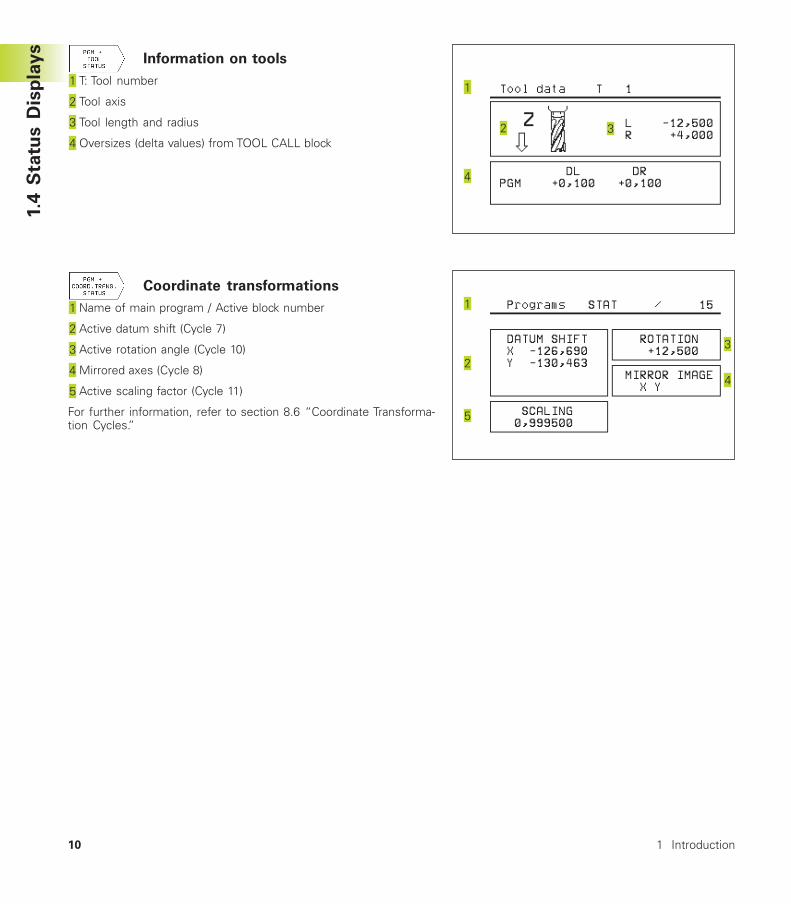
Information on tools
T: Tool number
Tool axis
Tool length and radius
Oversizes (delta values) from TOOL CALL block
Coordinate transformations
Name of main program / Active block number
Active datum shift (Cycle 7)
Active rotation angle (Cycle 10)
Mirrored axes (Cycle 8)
Active scaling factor (Cycle 11)
For further information, refer to section 8.6 “Coordinate Transforma-tion Cycles.”
1 Introduction
1.4
Sta
tus D
isp
lay
s
11HEIDENHAIN TNC 310
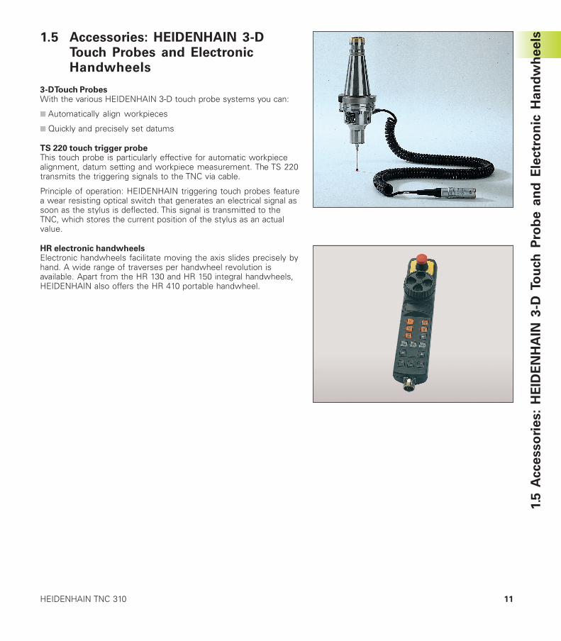
1.5 Accessories: HEIDENHAIN 3-DTouch Probes and ElectronicHandwheels
3-D Touch ProbesWith the various HEIDENHAIN 3-D touch probe systems you can:
■ Automatically align workpieces
■ Quickly and precisely set datums
TS 220 touch trigger probeThis touch probe is particularly effective for automatic workpiecealignment, datum setting and workpiece measurement. The TS 220transmits the triggering signals to the TNC via cable.
Principle of operation: HEIDENHAIN triggering touch probes featurea wear resisting optical switch that generates an electrical signal assoon as the stylus is deflected. This signal is transmitted to theTNC, which stores the current position of the stylus as an actualvalue.
HR electronic handwheelsElectronic handwheels facilitate moving the axis slides precisely byhand. A wide range of traverses per handwheel revolution isavailable. Apart from the HR 130 and HR 150 integral handwheels,HEIDENHAIN also offers the HR 410 portable handwheel.
1.5
A
cce
sso
rie
s:
HE
IDE
NH
AIN
3-D
To
uch
Pro
be a
nd
Ele
ctr
on
ic H
an
dw
heels

Manual Operation and Setup
2
14
2.1
Sw
itch
-On
2 Manual Operation and Setup
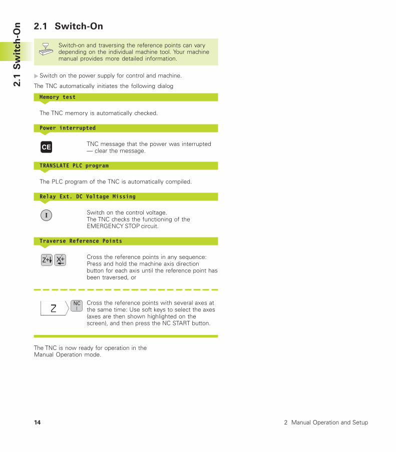
2.1 Switch-On
Switch-on and traversing the reference points can varydepending on the individual machine tool. Your machinemanual provides more detailed information.
�Switch on the power supply for control and machine.
The TNC automatically initiates the following dialog
Memory test<
The TNC memory is automatically checked.
Power interrupted<
TNC message that the power was interrupted— clear the message.
TRANSLATE PLC program<
The PLC program of the TNC is automatically compiled.
Relay Ext. DC Voltage Missing<
Switch on the control voltage.The TNC checks the functioning of theEMERGENCY STOP circuit.
Traverse Reference Points<
Cross the reference points in any sequence:Press and hold the machine axis directionbutton for each axis until the reference point hasbeen traversed, or
Cross the reference points with several axes atthe same time: Use soft keys to select the axes(axes are then shown highlighted on thescreen), and then press the NC START button.
The TNC is now ready for operation in theManual Operation mode.
15HEIDENHAIN TNC 310
2.2
Mo
vin
g t
he M
ach
ine A
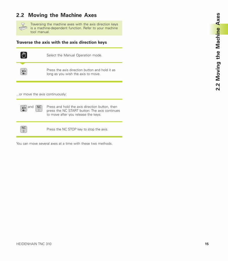
xes2.2 Moving the Machine Axes
Traversing the machine axes with the axis direction keysis a machine-dependent function. Refer to your machinetool manual.
Traverse the axis with the axis direction keys
Select the Manual Operation mode.
<
Press the axis direction button and hold it aslong as you wish the axis to move.
...or move the axis continuously:
and Press and hold the axis direction button, thenpress the NC START button: The axis continuesto move after you release the keys.
Press the NC STOP key to stop the axis.
You can move several axes at a time with these two methods.
16
2.2
Mo
vin
g t
he M
ach
ine A
xes
2 Manual Operation and Setup
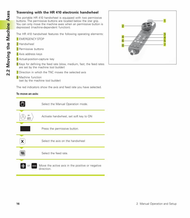
Traversing with the HR 410 electronic handwheel
The portable HR 410 handwheel is equipped with two permissivebuttons. The permissive buttons are located below the star grip.You can only move the machine axes when an permissive button isdepressed (machine-dependent function).
The HR 410 handwheel features the following operating elements:
EMERGENCY STOP
Handwheel
Permissive buttons
Axis address keys
Actual-position-capture key
Keys for defining the feed rate (slow, medium, fast; the feed ratesare set by the machine tool builder)
Direction in which the TNC moves the selected axis
Machine function(set by the machine tool builder)
The red indicators show the axis and feed rate you have selected.
To move an axis:
Select the Manual Operation mode.
<
Activate handwheel, set soft key to ON
<
Press the permissive button.
<
Select the axis on the handwheel
<
Select the feed rate.
<
or Move the active axis in the positive or negativedirection.
17HEIDENHAIN TNC 310
16X
Z
8
8
8
2.2
Mo
vin
g t
he M
ach
ine A
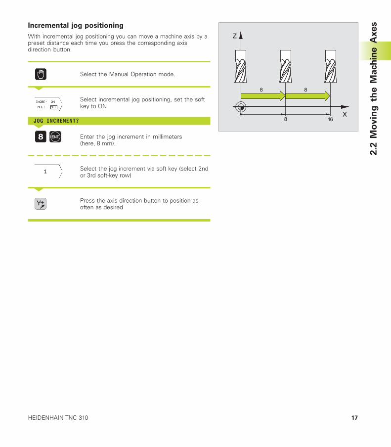
xesIncremental jog positioning
With incremental jog positioning you can move a machine axis by apreset distance each time you press the corresponding axisdirection button.
Select the Manual Operation mode.
<
Select incremental jog positioning, set the softkey to ON
JOG INCREMENT?<
Enter the jog increment in millimeters(here, 8 mm).
Select the jog increment via soft key (select 2ndor 3rd soft-key row)
<
Press the axis direction button to position asoften as desired
18 2 Manual Operation and Setup
2.3
Sp
ind
le S
peed
S,
Feed
Rate
F a
nd
Mis
cellan
eo
us F
un
cti
on
s M
2.3 Spindle Speed S, Feed Rate F andMiscellaneous Functions M
In the Manual Operation mode, enter the spindle speed S and themiscellaneous function M using soft keys. The miscellaneousfunctions are described in Chapter 7 ”Programming: MiscellaneousFunctions.” The feed rate is defined in a machine parameter and canbe changed only with the override knobs (see next page).
Entering valuesExample: Entering the spindle speed S
To enter the spindle speed, press the S soft key.
SPINDLE SPEED S=<
1000 Enter the desired spindle speed,
and confirm with the NC START button
The spindle speed S with the entered rpm is started with amiscellaneous function.
Proceed in the same way to enter the miscellaneous functions M.
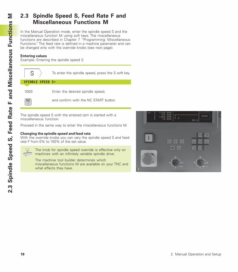
Changing the spindle speed and feed rateWith the override knobs you can vary the spindle speed S and feedrate F from 0% to 150% of the set value.
The knob for spindle speed override is effective only onmachines with an infinitely variable spindle drive.
The machine tool builder determines whichmiscellaneous functions M are available on your TNC andwhat effects they have.
19HEIDENHAIN TNC 310
Y
X
ZX
Y
2.4
Sett
ing
th
e D
atu
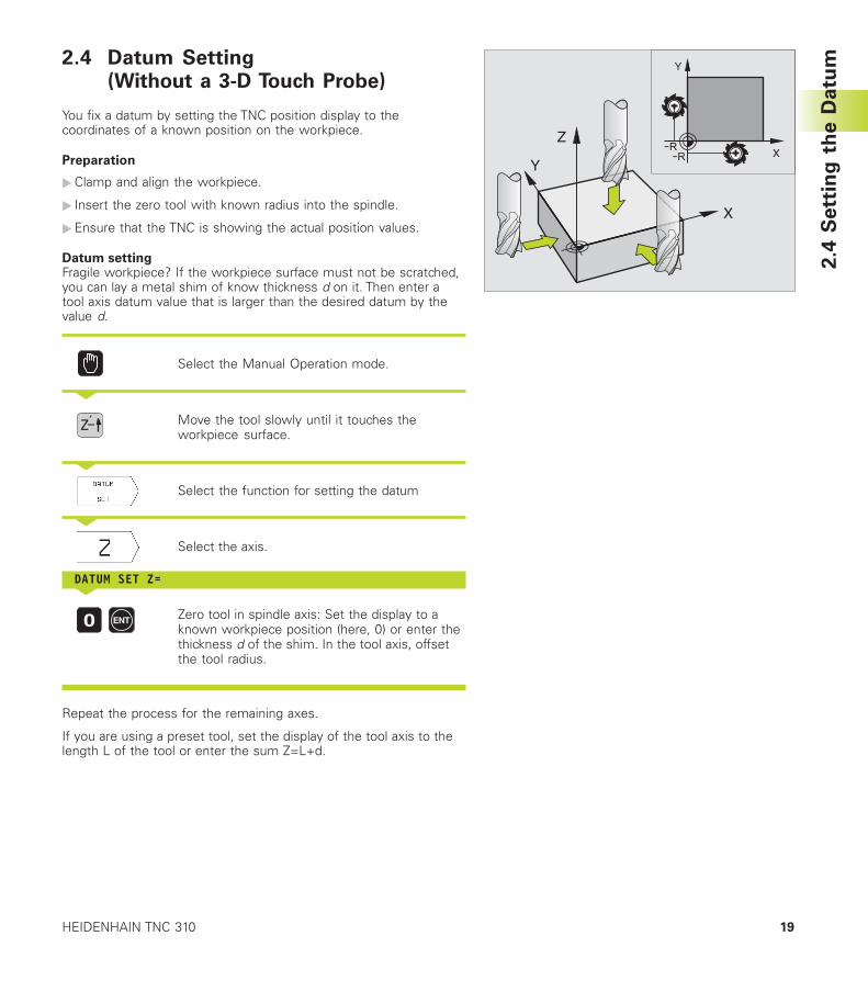
m2.4 Datum Setting(Without a 3-D Touch Probe)
You fix a datum by setting the TNC position display to thecoordinates of a known position on the workpiece.
Preparation
�Clamp and align the workpiece.
� Insert the zero tool with known radius into the spindle.
�Ensure that the TNC is showing the actual position values.
Datum settingFragile workpiece? If the workpiece surface must not be scratched,you can lay a metal shim of know thickness d on it. Then enter atool axis datum value that is larger than the desired datum by thevalue d.
Select the Manual Operation mode.
<
Move the tool slowly until it touches theworkpiece surface.
<
Select the function for setting the datum
<
Select the axis.
DATUM SET Z=<
Zero tool in spindle axis: Set the display to aknown workpiece position (here, 0) or enter thethickness d of the shim. In the tool axis, offsetthe tool radius.
Repeat the process for the remaining axes.
If you are using a preset tool, set the display of the tool axis to thelength L of the tool or enter the sum Z=L+d.

3Positioning with Manual DataInput (MDI)
22
3.1
Pro
gra
mm
ing
an
d E
xe
cu
tin
g S
imp
le P
osit
ion
ing
Blo
ck
s
3 Positioning with Manual Data Input (MDI)
3.1 Programming and Executing Sim-ple Positioning Blocks
The operating mode Positioning with Manual Data Input isparticularly convenient for simple machining operations or pre-positioning of the tool. You can write the a short program inHEIDENHAIN conversational programming and execute itimmediately. You can also call TNC cycles. The program is stored inthe file $MDI. In the operating mode Positioning with MDI, theadditional status displays can also be activated.
Select the Positioning with MDI mode ofoperation. Program the file $MDI as you wish.
To start program run, press the machine STARTbutton.
Limitations:
The following functions are not available:
- Tool radius compensation- Programming graphics- Programmable probing functions- Subprograms, program section repeats- Path functions CT, CR, RND and CHF- Cycle 12 PGM CALL
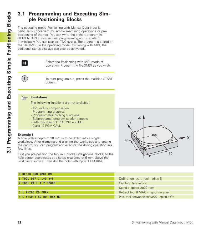
Example 1A hole with a depth of 20 mm is to be drilled into a singleworkpiece. After clamping and aligning the workpiece and settingthe datum, you can program and execute the drilling operation in afew lines.
First you pre-position the tool in L blocks (straight-line blocks) to thehole center coordinates at a setup clearance of 5 mm above theworkpiece surface. Then drill the hole with Cycle 1 PECKING.
0 BEGIN PGM $MDI MM1 TOOL DEF 1 L+0 R+52 TOOL CALL 1 Z S2000
3 L Z+200 R0 FMAX4 L X+50 Y+50 R0 FMAX M3
Y
X
Z
50
50
Define tool: zero tool, radius 5Call tool: tool axis ZSpindle speed 2000 rpmRetract tool (FMAX = rapid traverse)Pos. tool aboveholeatFMAX , spindle On
23HEIDENHAIN TNC 310
5 L Z+5 F20006 CYCL DEF 1.0 PECKING7 CYCL DEF 1.1 SET UP 58 CYCL DEF 1.2 DEPTH -209 CYCL DEF 1.3 PECKG 1010 CYCL DEF 1.4 DWELL 0.511 CYCL DEF 1.5 F25012 CYCL CALL13 L Z+200 R0 FMAX M214 END PGM $MDI MM
The straight-line function is described in section 6.4 “Path Contours— Cartesian Coordinates,” the PECKING cycle in section 8.3 “Dril-ling Cycles.”
3.1
Pro
gra
mm
ing
an
d E
xe
cu
tin
g S
imp
le P
osit
ion
ing
Blo
ck
sPosition tool to 5 mm above holeDefine PECKING cycle:Setup clearance of the tool above the holeTotal hole depth (Algebraic sign=working direction)Depth of each infeed before retractionDwell time in seconds at the hole bottomFeed rate for peckingCall PECKING cycleRetract toolEnd of program
24 3 Positioning with Manual Data Input (MDI)
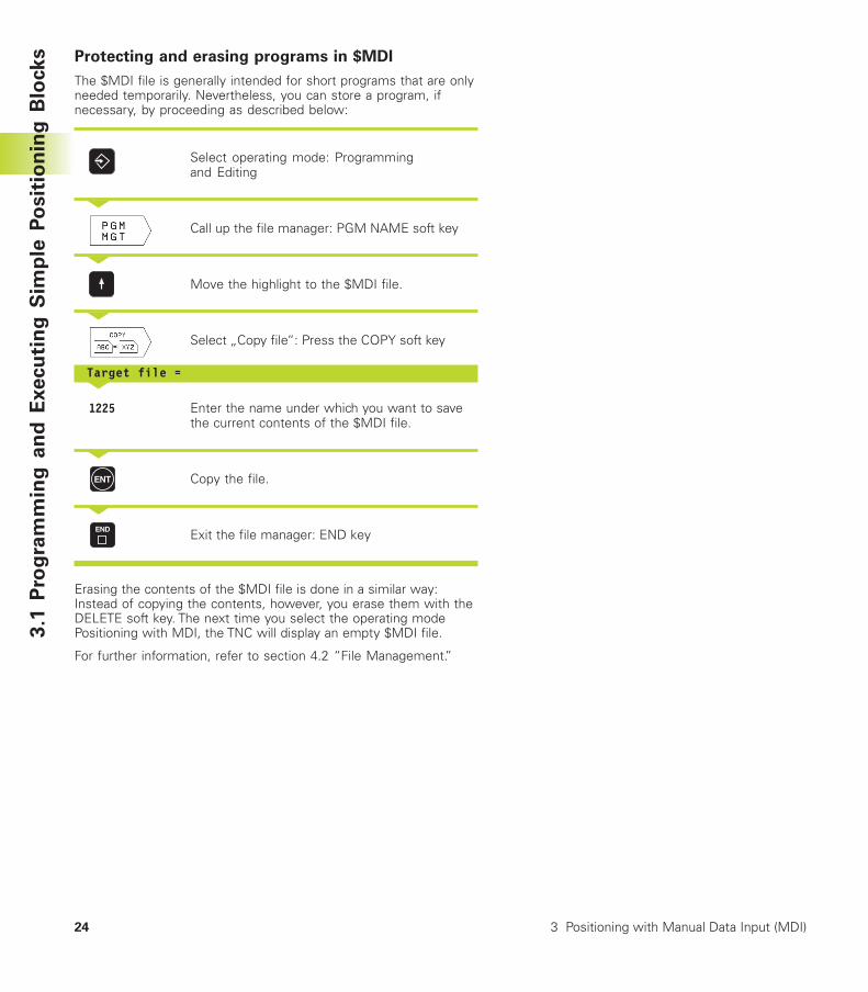
Protecting and erasing programs in $MDI
The $MDI file is generally intended for short programs that are onlyneeded temporarily. Nevertheless, you can store a program, ifnecessary, by proceeding as described below:
Select operating mode: Programmingand Editing
<
Call up the file manager: PGM NAME soft key
<
Move the highlight to the $MDI file.
<
Select „Copy file“: Press the COPY soft key
Target file =<
1225 Enter the name under which you want to savethe current contents of the $MDI file.
<
Copy the file.
<
Exit the file manager: END key
Erasing the contents of the $MDI file is done in a similar way:Instead of copying the contents, however, you erase them with theDELETE soft key. The next time you select the operating modePositioning with MDI, the TNC will display an empty $MDI file.
For further information, refer to section 4.2 “File Management.”
3.1
Pro
gra
mm
ing
an
d E
xe
cu
tin
g S
imp
le P
osit
ion
ing
Blo
ck
s
Programming:
Fundamentals of NC,File Management,Programming Aids
4
26 4 Programming: Fundamentals of NC, File Management, Programming Aids
4.1
Fu
nd
am
en
tals
of
NC 4.1 Fundamentals of NC
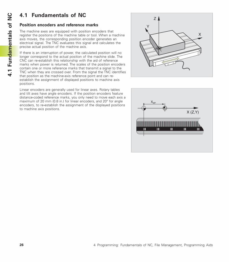
Position encoders and reference marks
The machine axes are equipped with position encoders thatregister the positions of the machine table or tool. When a machineaxis moves, the corresponding position encoder generates anelectrical signal. The TNC evaluates this signal and calculates theprecise actual position of the machine axis.
If there is an interruption of power, the calculated position will nolonger correspond to the actual position of the machine slide. TheCNC can re-establish this relationship with the aid of referencemarks when power is returned. The scales of the position encoderscontain one or more reference marks that transmit a signal to theTNC when they are crossed over. From the signal the TNC identifiesthat position as the machine-axis reference point and can re-establish the assignment of displayed positions to machine axispositions.
Linear encoders are generally used for linear axes. Rotary tablesand tilt axes have angle encoders. If the position encoders featuredistance-coded reference marks, you only need to move each axis amaximum of 20 mm (0.8 in.) for linear encoders, and 20° for angleencoders, to re-establish the assignment of the displayed positionsto machine axis positions.
Y
X
Z
X (Z,Y)
XMP
27HEIDENHAIN TNC 310
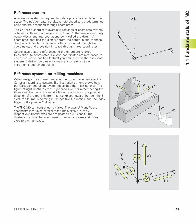
Reference system
A reference system is required to define positions in a plane or inspace. The position data are always referenced to a predeterminedpoint and are described through coordinates.
The Cartesian coordinate system (a rectangular coordinate system)is based on three coordinate axes X, Y and Z. The axes are mutuallyperpendicular and intersect at one point called the datum. Acoordinate identifies the distance from the datum in one of thesedirections. A position in a plane is thus described through twocoordinates, and a position in space through three coordinates.
Coordinates that are referenced to the datum are referredto as absolute coordinates. Relative coordinates are referenced toany other known position (datum) you define within the coordinatesystem. Relative coordinate values are also referred to asincremental coordinate values.
Reference systems on milling machines
When using a milling machine, you orient tool movements to theCartesian coordinate system. The illustration at right shows howthe Cartesian coordinate system describes the machine axes. Thefigure at right illustrates the “right-hand rule” for remembering thethree axis directions: the middle finger is pointing in the positivedirection of the tool axis from the workpiece toward the tool (the Zaxis), the thumb is pointing in the positive X direction, and the indexfinger in the positive Y direction.
The TNC 310 can control up to 4 axes. The axes U, V and W aresecondary linear axes parallel to the main axes X, Y and Z,respectively. Rotary axes are designated as A, B and C. Theillustration shows the assignment of secondary axes and rotaryaxes to the main axes.
4.1
Fu
nd
am
en
tals
of
NC
W+
C+
B+
V+ A+
U+
Y
X
Z
Y
X
Z
+X+Y
+Z
+X+Z+Y
28 4 Programming: Fundamentals of NC, File Management, Programming Aids
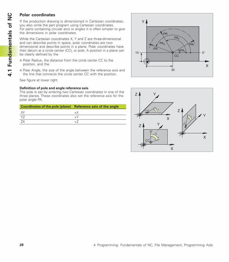
Polar coordinates
If the production drawing is dimensioned in Cartesian coordinates,you also write the part program using Cartesian coordinates.For parts containing circular arcs or angles it is often simpler to givethe dimensions in polar coordinates.
While the Cartesian coordinates X, Y and Z are three-dimensionaland can describe points in space, polar coordinates are two-dimensional and describe points in a plane. Polar coordinates havetheir datum at a circle center (CC), or pole. A position in a plane canbe clearly defined by the
■ Polar Radius, the distance from the circle center CC to theposition, and the
■ Polar Angle, the size of the angle between the reference axis andthe line that connects the circle center CC with the position.
See figure at lower right.
Definition of pole and angle reference axisThe pole is set by entering two Cartesian coordinates in one of thethree planes. These coordinates also set the reference axis for thepolar angle PA.
Coordinates of the pole (plane) Reference axis of the angle
XY +XYZ +YZX +Z
4.1
Fu
nd
am
en
tals
of
NC
X
Y
0°
30
10CC
PR PA1
PA2
PR
PR
PA3
X
Z Y
X
ZY
X
Z Y
29HEIDENHAIN TNC 310
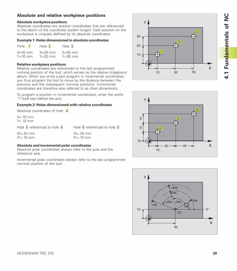
Absolute and relative workpiece positions
Absolute workpiece positionsAbsolute coordinates are position coordinates that are referencedto the datum of the coordinate system (origin). Each position on theworkpiece is uniquely defined by its absolute coordinates.
Example 1: Holes dimensioned in absolute coordinates
Hole Hole Hole
X=10 mm X=30 mm X=50 mmY=10 mm Y=20 mm Y=30 mm
Relative workpiece positionsRelative coordinates are referenced to the last programmednominal position of the tool, which serves as the relative (imaginary)datum. When you write a part program in incremental coordinates,you thus program the tool to move by the distance between theprevious and the subsequent nominal positions. Incrementalcoordinates are therefore also referred to as chain dimensions.
To program a position in incremental coordinates, enter the prefix“I”(soft key) before the axis.
Example 2: Holes dimensioned with relative coordinates
Absolute coordinates of hole :
X= 10 mmY= 10 mm
Hole referenced to hole Hole referenced to hole
IX= 20 mm IX= 20 mmIY= 10 mm IY= 10 mm
Absolute and incremental polar coordinatesAbsolute polar coordinates always refer to the pole and thereference axis.
Incremental polar coordinates always refer to the last programmednominal position of the tool.
X
Y
0°
30
10CC
PR PA+IPA PR
PR
+IPA
+IPR
4.1
Fu
nd
am
en
tals
of
NC
X
Y
30
20
503010
101
2
3
X
Y
20
1010
2010
10
6
5
4
30 4 Programming: Fundamentals of NC, File Management, Programming Aids
Y
X
Z
X
Y
325
320
0
450 900
950
150
-150
750
0
300±
0,1
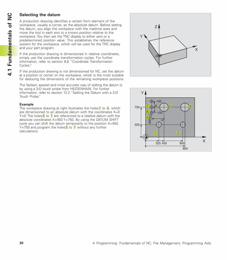
Selecting the datum
A production drawing identifies a certain form element of theworkpiece, usually a corner, as the absolute datum. Before settingthe datum, you align the workpiece with the machine axes andmove the tool in each axis to a known position relative to theworkpiece. You then set the TNC display to either zero or apredetermined position value. This establishes the referencesystem for the workpiece, which will be used for the TNC displayand your part program.
If the production drawing is dimensioned in relative coordinates,simply use the coordinate transformation cycles. For furtherinformation, refer to section 8.6 “Coordinate TransformationCycles.”
If the production drawing is not dimensioned for NC, set the datumat a position or corner on the workpiece, which is the most suitablefor deducing the dimensions of the remaining workpiece positions.
The fastest, easiest and most accurate way of setting the datum isby using a 3-D touch probe from HEIDENHAIN. For furtherinformation, refer to section 12.2 “Setting the Datum with a 3-DTouch Probe.”
ExampleThe workpiece drawing at right illustrates the holes to , whichare dimensioned to an absolute datum with the coordinates X=0Y=0. The holes to are referenced to a relative datum with theabsolute coordinates X=450 Y=750. By using the DATUM SHIFTcycle you can shift the datum temporarily to the position X=450,Y=750 and program the holes to without any furthercalculations.
7
6
5
1 2
3 4
4.1
Fu
nd
am
en
tals
of
NC
31HEIDENHAIN TNC 310
4.2 File management
Files and file management
When you write a part program on the TNC, you must first enter afile name. The TNC then stores the program as a file with the samename. You can also store tables as files.
File namesThe name of a file can have up to 8 characters. When you storeprograms and tables as files, the TNC adds an extension to the filename, separated by a point. This extension identifies the file type(see table at right).
35720 .H
File name File type
The TNC can manage up to 64 files. Their total size, however, mustnot exceed 128 MB.
Working with the file manager
This section informs you about the meaning of the individualscreen information, and describes how to select files. If you are notyet familiar with the TNC file manager, we recommend that youread this section completely and test the individual functions onyour TNC.
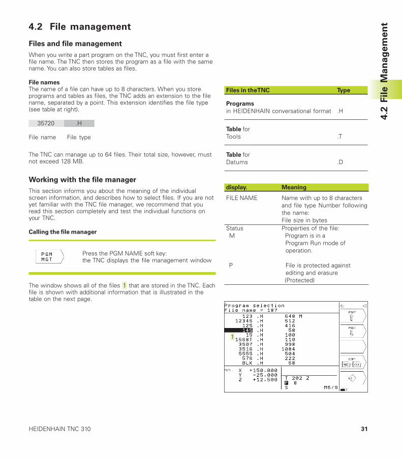
Calling the file manager
Press the PGM NAME soft key:the TNC displays the file management window
The window shows all of the files that are stored in the TNC. Eachfile is shown with additional information that is illustrated in thetable on the next page.
4.2
Fil
e M
an
ag
em
en
t
Files in the TNC Type
Programs
in HEIDENHAIN conversational format .H
Table forTools .T
Table forDatums .D
display. Meaning
FILE NAME Name with up to 8 charactersand file type Number followingthe name:File size in bytes
Status Properties of the file:M Program is in a
Program Run mode of operation.
P File is protected against editing and erasure(Protected)
32 4 Programming: Fundamentals of NC, File Management, Programming Aids
Selecting a file
Calling the file manager
<
Use the arrow keys to move the highlight to the desired file:
Move the highlight up or down.
Enter the first or more numbers of the file you wish to select andthen press the GOTO key: The highlight moves to the first file thatmatches these numbers.
<
The selected file is opened in the operatingmode from which you have the called filemanager: Press ENT.
Copying a file
�Move the highlight to the file you wish to copy.
� Press the COPY soft key to select the copyingfunction.
�Enter the name of the destination file and confirm your entry withthe ENT key: The TNC copies the file. The original file is retained.
Renaming a file
�Move the highlight to the file you wish to rename.
� Select the renaming function.
� Enter the new file name; the file type cannot bechanged.
� To execute renaming, press the ENT key.
4.2
Fil
e M
an
ag
em
en
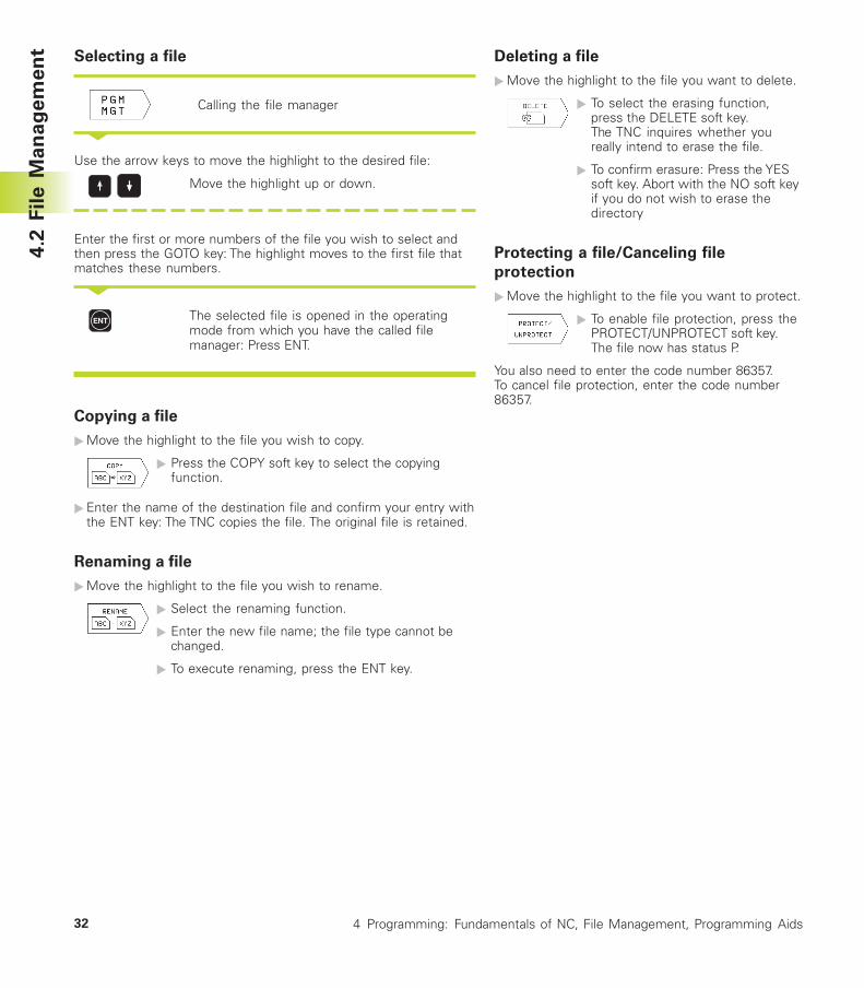
t Deleting a file
�Move the highlight to the file you want to delete.
� To select the erasing function,press the DELETE soft key.The TNC inquires whether youreally intend to erase the file.
� To confirm erasure: Press the YESsoft key. Abort with the NO soft keyif you do not wish to erase thedirectory
Protecting a file/Canceling file
protection
�Move the highlight to the file you want to protect.
� To enable file protection, press thePROTECT/UNPROTECT soft key.The file now has status P.
You also need to enter the code number 86357.To cancel file protection, enter the code number86357.
33HEIDENHAIN TNC 310
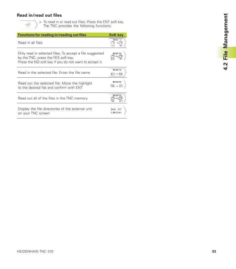
Read in/read out files
� To read in or read out files: Press the ENT soft key.The TNC provides the following functions:
Functions for reading in/reading out files Soft key
Read in all files
Only read in selected files; To accept a file suggestedby the TNC, press the YES soft key;Press the NO soft key if you do not want to accept it.
Read in the selected file: Enter the file name
Read out the selected file: Move the highlightto the desired file and confirm with ENT
Read out all of the files in the TNC memory
Display the file directories of the external uniton your TNC screen
4.2
Fil
e M
an
ag
em
en
t
34 4 Programming: Fundamentals of NC, File Management, Programming Aids
4.3 Creating and Writing Programs
Organization of an NC program in HEIDENHAIN
conversational format.
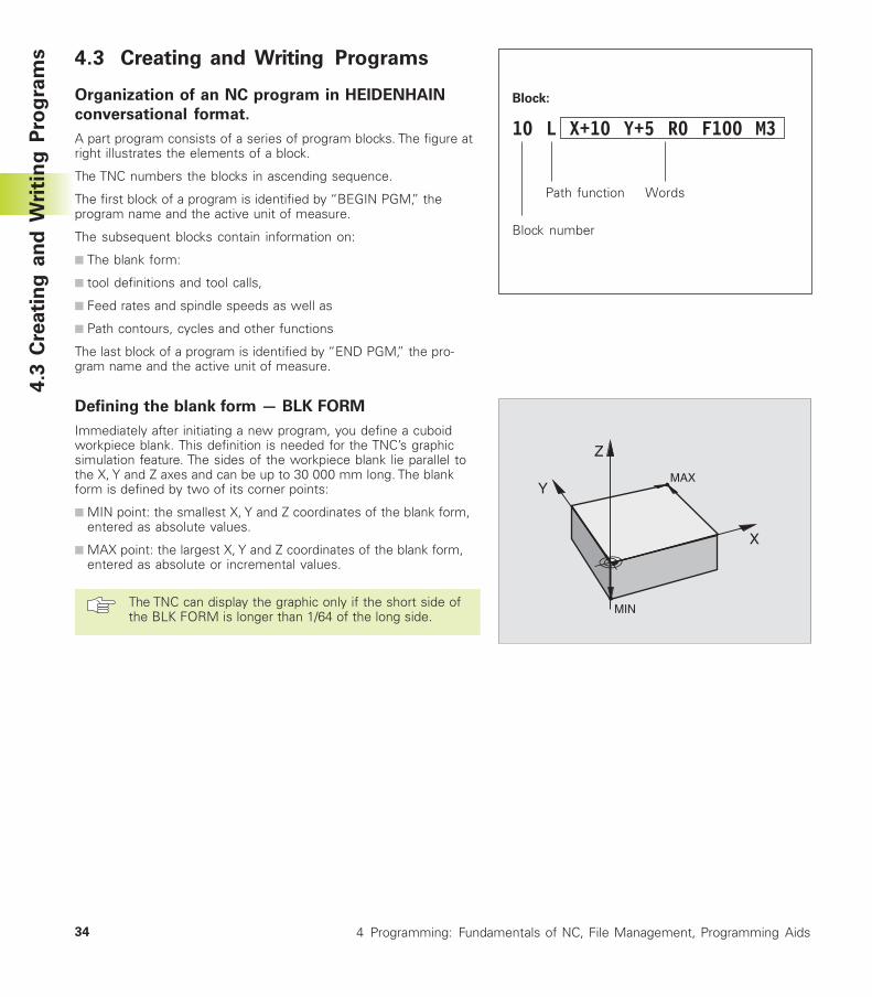
A part program consists of a series of program blocks. The figure atright illustrates the elements of a block.
The TNC numbers the blocks in ascending sequence.
The first block of a program is identified by “BEGIN PGM,” theprogram name and the active unit of measure.
The subsequent blocks contain information on:
■ The blank form:
■ tool definitions and tool calls,
■ Feed rates and spindle speeds as well as
■ Path contours, cycles and other functions
The last block of a program is identified by “END PGM,” the pro-gram name and the active unit of measure.
Defining the blank form — BLK FORM
Immediately after initiating a new program, you define a cuboidworkpiece blank. This definition is needed for the TNC’s graphicsimulation feature. The sides of the workpiece blank lie parallel tothe X, Y and Z axes and can be up to 30 000 mm long. The blankform is defined by two of its corner points:
■ MIN point: the smallest X, Y and Z coordinates of the blank form,entered as absolute values.
■ MAX point: the largest X, Y and Z coordinates of the blank form,entered as absolute or incremental values.
The TNC can display the graphic only if the short side ofthe BLK FORM is longer than 1/64 of the long side.
4.3
Cre
ati
ng
an
d W
riti
ng
Pro
gra
ms
Y
X
Z
MAX
MIN
Block:
10 L X+10 Y+5 R0 F100 M3
Path function Words
Block number
35HEIDENHAIN TNC 310
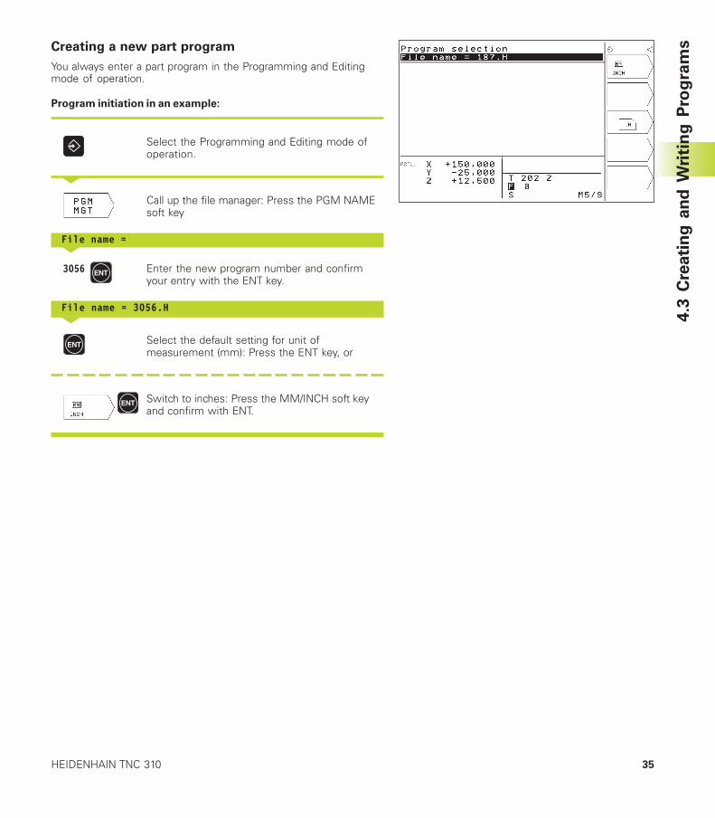
Creating a new part program
You always enter a part program in the Programming and Editingmode of operation.
Program initiation in an example:
Select the Programming and Editing mode ofoperation.
<
Call up the file manager: Press the PGM NAMEsoft key
File name =<
3056 Enter the new program number and confirmyour entry with the ENT key.
File name = 3056.H<
Select the default setting for unit ofmeasurement (mm): Press the ENT key, or
Switch to inches: Press the MM/INCH soft keyand confirm with ENT.
4.3
Cre
ati
ng
an
d W
riti
ng
Pro
gra
ms
36 4 Programming: Fundamentals of NC, File Management, Programming Aids
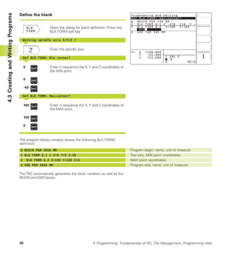
Define the blank
Open the dialog for blank definition: Press theBLK FORM soft key
Working spindle axis X/Y/Z ?<
Enter the spindle axis.
Def BLK FORM: Min corner?<
0 Enter in sequence the X, Y and Z coordinates ofthe MIN point.
0
-40
Def BLK FORM: Max-corner?<
100 Enter in sequence the X, Y and Z coordinates ofthe MAX point.
100
0
The program blocks window shows the following BLK FORMdefinition
0 BEGIN PGM 3056 MM1 BLK FORM 0.1 Z X+0 Y+0 Z-402 BLK FORM 0.2 X+100 Y+100 Z+03 END PGM 3056 MM
The TNC automatically generates the block numbers as well as theBEGIN and END blocks.
Program begin, name, unit of measureTool axis, MIN point coordinatesMAX point coordinatesProgram end, name, unit of measure
4.3
Cre
ati
ng
an
d W
riti
ng
Pro
gra
ms
37HEIDENHAIN TNC 310
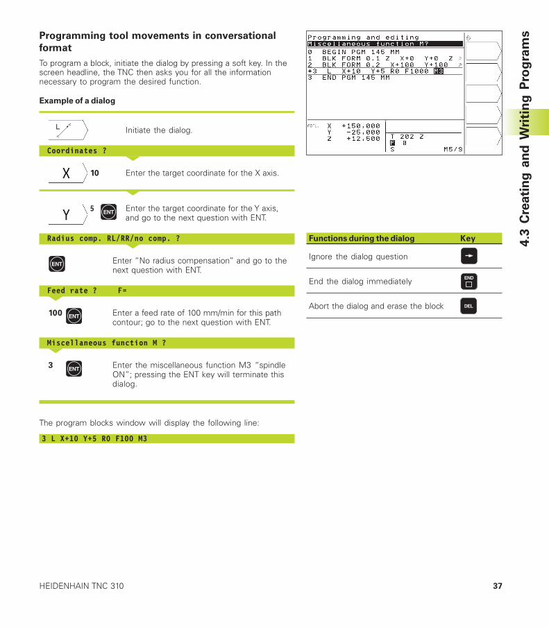
Programming tool movements in conversational
format
To program a block, initiate the dialog by pressing a soft key. In thescreen headline, the TNC then asks you for all the informationnecessary to program the desired function.
Example of a dialog
Initiate the dialog.
Coordinates ?<
10 Enter the target coordinate for the X axis.
<
5 Enter the target coordinate for the Y axis,and go to the next question with ENT.
Radius comp. RL/RR/no comp. ?<
Enter “No radius compensation” and go to thenext question with ENT.
Feed rate ? F=<
100 Enter a feed rate of 100 mm/min for this pathcontour; go to the next question with ENT.
Miscellaneous function M ?<
3 Enter the miscellaneous function M3 “spindleON”; pressing the ENT key will terminate thisdialog.
The program blocks window will display the following line:
3 L X+10 Y+5 R0 F100 M3
Functions during the dialog Key
Ignore the dialog question
End the dialog immediately
Abort the dialog and erase the block
4.3
Cre
ati
ng
an
d W
riti
ng
Pro
gra
ms
38 4 Programming: Fundamentals of NC, File Management, Programming Aids
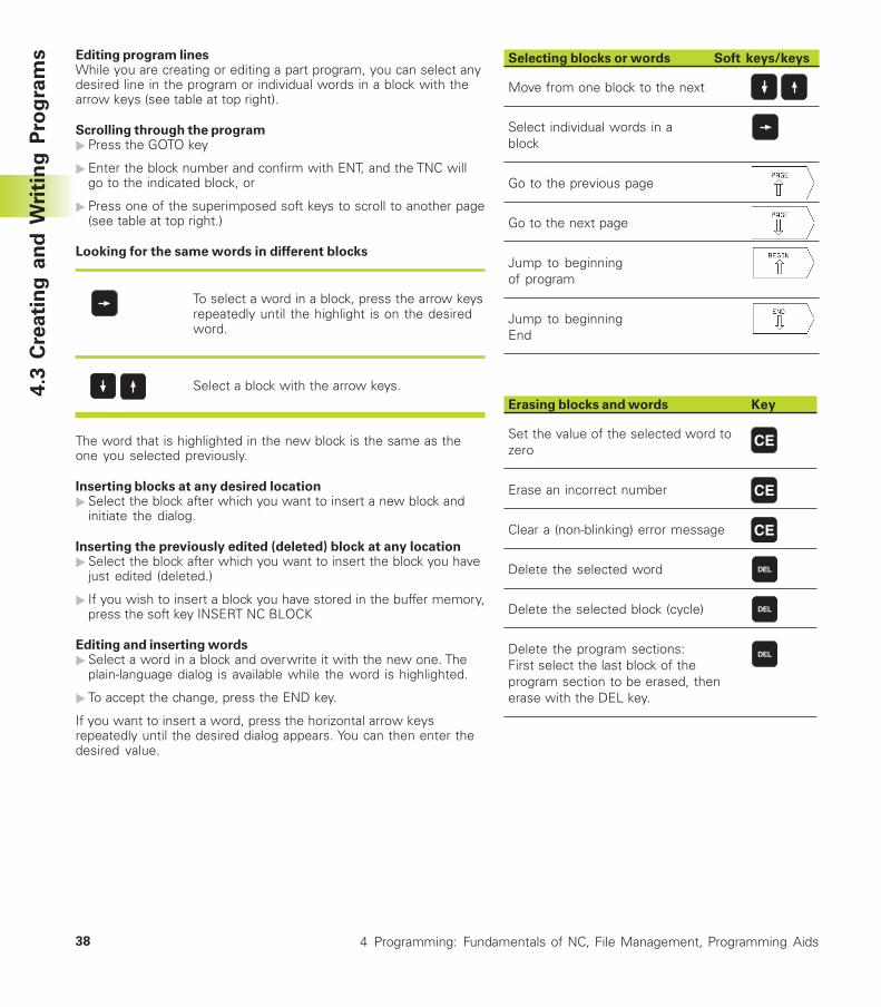
Editing program linesWhile you are creating or editing a part program, you can select anydesired line in the program or individual words in a block with thearrow keys (see table at top right).
Scrolling through the program�Press the GOTO key
�Enter the block number and confirm with ENT, and the TNC willgo to the indicated block, or
�Press one of the superimposed soft keys to scroll to another page(see table at top right.)
Looking for the same words in different blocks
To select a word in a block, press the arrow keysrepeatedly until the highlight is on the desiredword.
Select a block with the arrow keys.
The word that is highlighted in the new block is the same as theone you selected previously.
Inserting blocks at any desired location�Select the block after which you want to insert a new block and
initiate the dialog.
Inserting the previously edited (deleted) block at any location�Select the block after which you want to insert the block you have
just edited (deleted.)
� If you wish to insert a block you have stored in the buffer memory,press the soft key INSERT NC BLOCK
Editing and inserting words�Select a word in a block and overwrite it with the new one. The
plain-language dialog is available while the word is highlighted.
� To accept the change, press the END key.
If you want to insert a word, press the horizontal arrow keysrepeatedly until the desired dialog appears. You can then enter thedesired value.
Selecting blocks or words Soft keys/keys
Move from one block to the next
Select individual words in ablock
Go to the previous page
Go to the next page
Jump to beginningof program
Jump to beginningEnd
Erasing blocks and words Key
Set the value of the selected word tozero
Erase an incorrect number
Clear a (non-blinking) error message
Delete the selected word
Delete the selected block (cycle)
Delete the program sections:First select the last block of theprogram section to be erased, thenerase with the DEL key.
4.3
Cre
ati
ng
an
d W
riti
ng
Pro
gra
ms
39HEIDENHAIN TNC 310
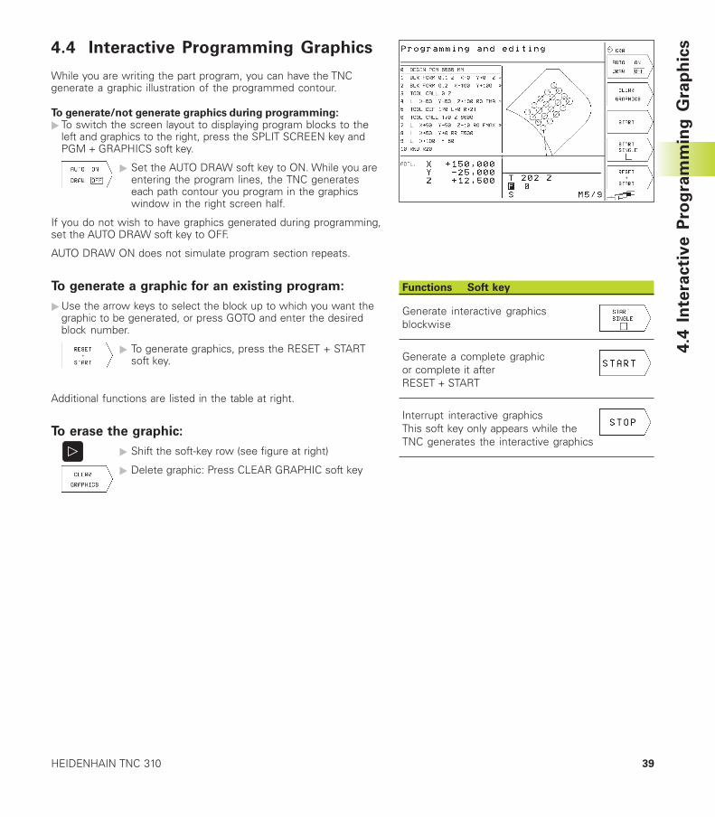
4.4 Interactive Programming Graphics
While you are writing the part program, you can have the TNCgenerate a graphic illustration of the programmed contour.
To generate/not generate graphics during programming:� To switch the screen layout to displaying program blocks to the
left and graphics to the right, press the SPLIT SCREEN key andPGM + GRAPHICS soft key.
� Set the AUTO DRAW soft key to ON. While you areentering the program lines, the TNC generateseach path contour you program in the graphicswindow in the right screen half.
If you do not wish to have graphics generated during programming,set the AUTO DRAW soft key to OFF.
AUTO DRAW ON does not simulate program section repeats.
To generate a graphic for an existing program:
�Use the arrow keys to select the block up to which you want thegraphic to be generated, or press GOTO and enter the desiredblock number.
� To generate graphics, press the RESET + STARTsoft key.
Additional functions are listed in the table at right.
To erase the graphic:
� Shift the soft-key row (see figure at right)
� Delete graphic: Press CLEAR GRAPHIC soft key
Functions Soft key
Generate interactive graphicsblockwise
Generate a complete graphicor complete it afterRESET + START
Interrupt interactive graphicsThis soft key only appears while theTNC generates the interactive graphics
4.4
In
tera
cti
ve
Pro
gra
mm
ing
Gra
ph
ics
40 4 Programming: Fundamentals of NC, File Management, Programming Aids
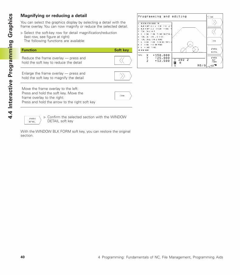
Magnifying or reducing a detail
You can select the graphics display by selecting a detail with theframe overlay. You can now magnify or reduce the selected detail.
�Select the soft-key row for detail magnification/reduction(last row, see figure at right)The following functions are available:
Function Soft key
Reduce the frame overlay — press andhold the soft key to reduce the detail
Enlarge the frame overlay — press andhold the soft key to magnify the detail
Move the frame overlay to the left:Press and hold the soft key. Move theframe overlay to the right:Press and hold the arrow to the right soft key
� Confirm the selected section with the WINDOWDETAIL soft key
With the WINDOW BLK FORM soft key, you can restore the originalsection.
4.4
In
tera
cti
ve
Pro
gra
mm
ing
Gra
ph
ics
41HEIDENHAIN TNC 310
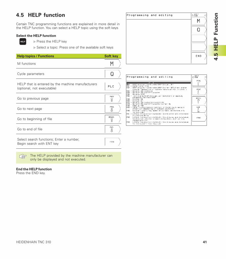
4.5 HELP function
Certain TNC programming functions are explained in more detail inthe HELP function. You can select a HELP topic using the soft keys.
Select the HELP function
�Press the HELP key
�Select a topic: Press one of the available soft keys
Help topics / Functions Soft key
M functions
Cycle parameters
HELP that is entered by the machine manufacturers(optional, not executable)
Go to previous page
Go to next page
Go to beginning of file
Go to end of file
Select search functions; Enter a number,Begin search with ENT key
The HELP provided by the machine manufacturer canonly be displayed and not executed.
End the HELP functionPress the END key.
4.5
HE
LP
Fu
ncti
on

Programming:
Tools
5
44 5 Programming: Tools
5.1 Entering Tool-Related Data
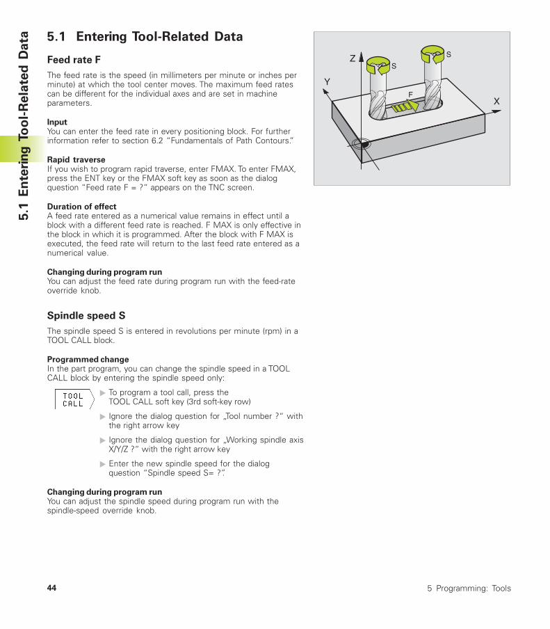
Feed rate F
The feed rate is the speed (in millimeters per minute or inches perminute) at which the tool center moves. The maximum feed ratescan be different for the individual axes and are set in machineparameters.
InputYou can enter the feed rate in every positioning block. For furtherinformation refer to section 6.2 “Fundamentals of Path Contours.”
Rapid traverseIf you wish to program rapid traverse, enter FMAX. To enter FMAX,press the ENT key or the FMAX soft key as soon as the dialogquestion “Feed rate F = ?” appears on the TNC screen.
Duration of effectA feed rate entered as a numerical value remains in effect until ablock with a different feed rate is reached. F MAX is only effective inthe block in which it is programmed. After the block with F MAX isexecuted, the feed rate will return to the last feed rate entered as anumerical value.
Changing during program runYou can adjust the feed rate during program run with the feed-rateoverride knob.
Spindle speed S
The spindle speed S is entered in revolutions per minute (rpm) in aTOOL CALL block.
Programmed changeIn the part program, you can change the spindle speed in a TOOLCALL block by entering the spindle speed only:
� To program a tool call, press theTOOL CALL soft key (3rd soft-key row)
� Ignore the dialog question for „Tool number ?“ withthe right arrow key
� Ignore the dialog question for „Working spindle axisX/Y/Z ?“ with the right arrow key
� Enter the new spindle speed for the dialogquestion “Spindle speed S= ?”.
Changing during program runYou can adjust the spindle speed during program run with thespindle-speed override knob.
5.1
En
teri
ng
To
ol-
Re
late
d D
ata
X
Y
ZS
S
F
45HEIDENHAIN TNC 310
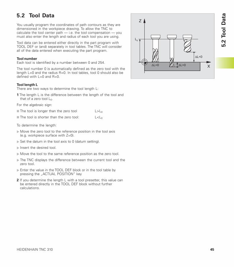
5.2 Tool Data
You usually program the coordinates of path contours as they aredimensioned in the workpiece drawing. To allow the TNC tocalculate the tool center path — i.e. the tool compensation — youmust also enter the length and radius of each tool you are using.
Tool data can be entered either directly in the part program withTOOL DEF or (and) separately in tool tables. The TNC will considerall of the data entered when executing the part program.
Tool numberEach tool is identified by a number between 0 and 254.
The tool number 0 is automatically defined as the zero tool with thelength L=0 and the radius R=0. In tool tables, tool 0 should also bedefined with L=0 and R=0.
Tool length LThere are two ways to determine the tool length L:
1 The length L is the difference between the length of the tool andthat of a zero tool L0.
For the algebraic sign:
■ The tool is longer than the zero tool L>L0
■ The tool is shorter than the zero tool: L<L0
To determine the length:
�Move the zero tool to the reference position in the tool axis(e.g. workpiece surface with Z=0).
�Set the datum in the tool axis to 0 (datum setting).
� Insert the desired tool.
�Move the tool to the same reference position as the zero tool.
� The TNC displays the difference between the current tool and thezero tool.
�Enter the value in the TOOL DEF block or in the tool table bypressing the „ACTUAL POSITION“ key
2 If you determine the length L with a tool presetter, this value canbe entered directly in the TOOL DEF block without furthercalculations.
5.2
To
ol
Data
Z
X
L0
46 5 Programming: Tools
5.2
To
ol
Data
DR<0
DR>0
DL<0
R
DL>0
L
R
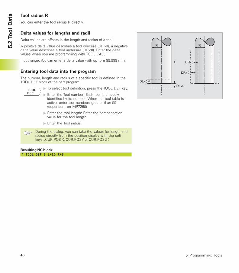
Tool radius R
You can enter the tool radius R directly.
Delta values for lengths and radii
Delta values are offsets in the length and radius of a tool.
A positive delta value describes a tool oversize (DR>0), a negativedelta value describes a tool undersize (DR<0). Enter the deltavalues when you are programming with TOOL CALL.
Input range: You can enter a delta value with up to ± 99.999 mm.
Entering tool data into the program
The number, length and radius of a specific tool is defined in theTOOL DEF block of the part program.
� To select tool definition, press the TOOL DEF key.
� Enter the Tool number: Each tool is uniquelyidentified by its number. When the tool table isactive, enter tool numbers greater than 99(dependent on MP7260)
� Enter the tool length: Enter the compensationvalue for the tool length.
� Enter the Tool radius.
During the dialog, you can take the values for length andradius directly from the position display with the softkeys „CUR.POS X, CUR.POS Y or CUR.POS Z“.
Resulting NC block:
4 TOOL DEF 5 L+10 R+5
47HEIDENHAIN TNC 310
Entering tool data in tables
You can define and store up to 254 tools and their tool data in thetool table (the maximum number of tools in the table can be set inmachine parameter 7260).
Tool table: Available input data
5.2
To
ol
Data
Abbr. Input
T Number by which the tool is called in the programL Value for tool length compensation LR Compensation value for the tool radius R
Dialog
–Tool length?Tool radius?
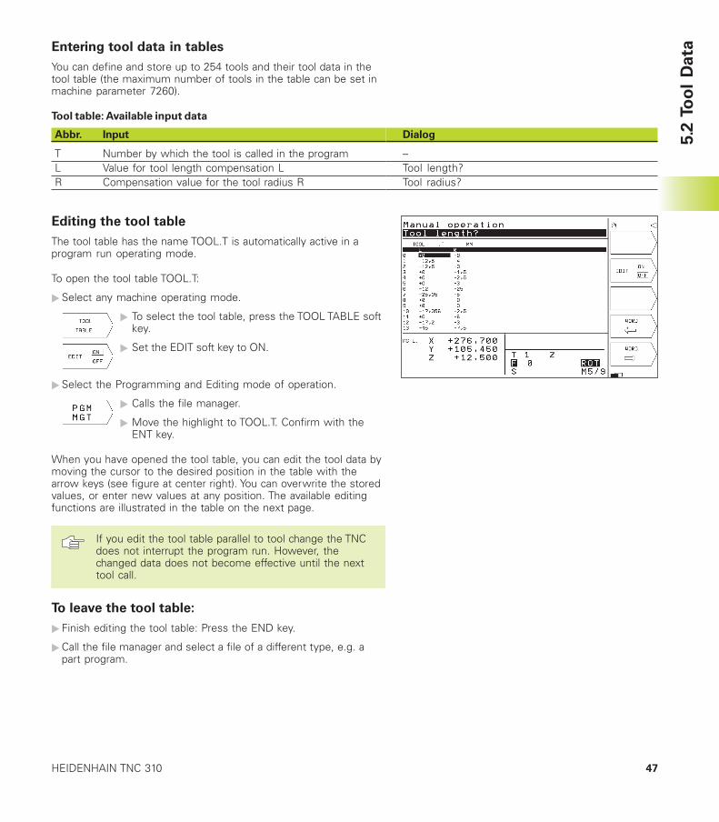
Editing the tool table
The tool table has the name TOOL.T is automatically active in aprogram run operating mode.
To open the tool table TOOL.T:
�Select any machine operating mode.
� To select the tool table, press the TOOL TABLE softkey.
� Set the EDIT soft key to ON.
�Select the Programming and Editing mode of operation.
� Calls the file manager.
� Move the highlight to TOOL.T. Confirm with theENT key.
When you have opened the tool table, you can edit the tool data bymoving the cursor to the desired position in the table with thearrow keys (see figure at center right). You can overwrite the storedvalues, or enter new values at any position. The available editingfunctions are illustrated in the table on the next page.
If you edit the tool table parallel to tool change the TNCdoes not interrupt the program run. However, thechanged data does not become effective until the nexttool call.
To leave the tool table:
� Finish editing the tool table: Press the END key.
�Call the file manager and select a file of a different type, e.g. apart program.
48 5 Programming: Tools
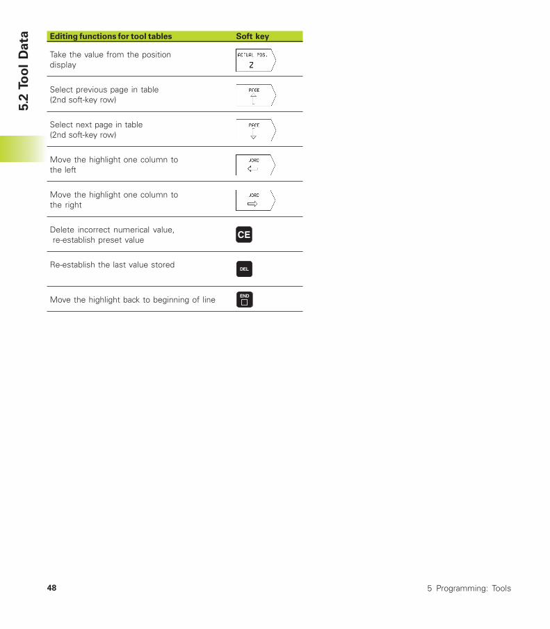
Editing functions for tool tables Soft key
Take the value from the positiondisplay
Select previous page in table(2nd soft-key row)
Select next page in table(2nd soft-key row)
Move the highlight one column tothe left
Move the highlight one column tothe right
Delete incorrect numerical value, re-establish preset value
Re-establish the last value stored
Move the highlight back to beginning of line
5.2
To
ol
Data
49HEIDENHAIN TNC 310
Calling tool data
A TOOL CALL block in the part program is defined with thefollowing data:
� Select the tool call function with the TOOL CALLkey
� Tool number: Enter the number of the tool. Thetool must already be defined in a TOOL DEF blockor in the tool table.
� Working spindle axis X/Y/Z: Enter the tool axis.
� Spindle speed S
� Tool length oversize: Enter the delta value for thetool length.
� Tool radius oversize: Enter the delta value for thetool radius.
Example:Call tool number 5 in the tool axis Z with a spindle speed 2500 rpm.The tool length is to be programmed with an oversize of 0.2 mm,the tool radius with an undersize of 1 mm.
20 TOOL CALL 5 Z S2500 DL+0.2 DR-1
The character D preceding L and R designates delta values.
Tool change
The tool change function can vary depending on theindividual machine tool. Refer to your machine toolmanual.
Tool change positionA tool change position must be approachable without collision. Withthe miscellaneous functions M91 and M92, you can enter machine-referenced (rather than workpiece-referenced) coordinates for thetool change position. If TOOL CALL 0 is programmed before thefirst tool call, the TNC moves the tool spindle in the tool axis to aposition that is independent of the tool length.
Manual tool changeTo change the tool manually, stop the spindle and move the tool tothe tool change position:
�Move to the tool change position under program control.
� Interrupt program run (see section 11.3 “Program Run”).
�Change the tool.
�Resume the program run (see section 11.3 “Program Run”).5.2
To
ol
Data
50 5 Programming: Tools
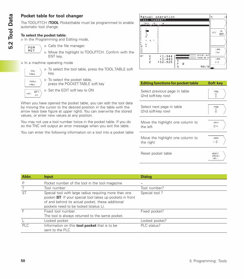
Pocket table for tool changer
The TOOLP.TCH (TOOL Pocket)table must be programmed to enableautomatic tool change.
To select the pocket table:� In the Programming and Editing mode,
� Calls the file manager.
� Move the highlight to TOOLP.TCH. Confirm with theENT key.
� In a machine operating mode
� To select the tool table, press the TOOL TABLE softkey.
� To select the pocket table,press the POCKET TABLE soft key
� Set the EDIT soft key to ON
When you have opened the pocket table, you can edit the tool databy moving the cursor to the desired position in the table with thearrow keys (see figure at upper right). You can overwrite the storedvalues, or enter new values at any position.
You may not use a tool number twice in the pocket table. If you doso the TNC will output an error message when you exit the table.
You can enter the following information on a tool into a pocket table
Abbr. Input
P Pocket number of the tool in the tool magazineT Tool numberST Special tool with large radius requiring more than one
pocket (ST: If your special tool takes up pockets in frontof and behind its actual pocket, these additionalpockets need to be locked (status L).
F Fixed tool number.The tool is always returned to the same pocket.
L Locked pocketPLC Information on this tool pocket that is to be
sent to the PLC
Dialog
–Tool number?Special tool ?
Fixed pocket?
Locked pocket?PLC status?
5.2
To
ol
Data
Editing functions for pocket table Soft key
Select previous page in table(2nd soft-key row)
Select next page in table(2nd soft-key row)
Move the highlight one column tothe left
Move the highlight one column tothe right
Reset pocket table
51HEIDENHAIN TNC 310
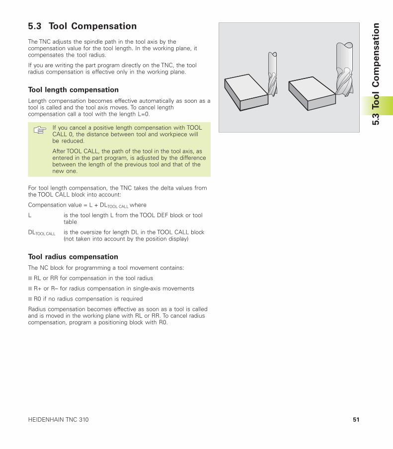
5.3 Tool Compensation
The TNC adjusts the spindle path in the tool axis by thecompensation value for the tool length. In the working plane, itcompensates the tool radius.
If you are writing the part program directly on the TNC, the toolradius compensation is effective only in the working plane.
Tool length compensation
Length compensation becomes effective automatically as soon as atool is called and the tool axis moves. To cancel lengthcompensation call a tool with the length L=0.
If you cancel a positive length compensation with TOOLCALL 0, the distance between tool and workpiece willbe reduced.
After TOOL CALL, the path of the tool in the tool axis, asentered in the part program, is adjusted by the differencebetween the length of the previous tool and that of thenew one.
For tool length compensation, the TNC takes the delta values fromthe TOOL CALL block into account:
Compensation value = L + DLTOOL CALL where
L is the tool length L from the TOOL DEF block or tooltable
DLTOOL CALL is the oversize for length DL in the TOOL CALL block(not taken into account by the position display)
Tool radius compensation
The NC block for programming a tool movement contains:
■ RL or RR for compensation in the tool radius
■ R+ or R– for radius compensation in single-axis movements
■ R0 if no radius compensation is required
Radius compensation becomes effective as soon as a tool is calledand is moved in the working plane with RL or RR. To cancel radiuscompensation, program a positioning block with R0.
5.3
To
ol
Co
mp
en
sa
tio
n
52 5 Programming: Tools
For tool radius compensation, the TNC takes the delta values fromthe TOOL CALL block into account:
Compensation value = R + DRTOOL CALL, where
R is the tool radius R from the TOOL DEF block or tooltable
DRTOOL CALL is the oversize for radius DR in the TOOL CALL block(not taken into account by the position display)
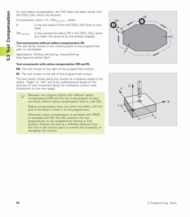
Tool movements without radius compensation: R0The tool center moves in the working plane to the programmedpath or coordinates.
Applications: Drilling and boring, pre-positioning(see figure at center right)
Tool movements with radius compensation: RR and RL
RR The tool moves to the right of the programmed contour
RL The tool moves to the left of the programmed contour
The tool center moves along the contour at a distance equal to theradius. “Right” or “left” are to be understood as based on thedirection of tool movement along the workpiece contour (seeillustrations on the next page).
Between two program blocks with different radiuscompensations (RR and RL) you must program at leastone block without radius compensation (that is, with R0).
Radius compensation does not come into effect until theend of the block in which it is first programmed.
Whenever radius compensation is activated with RR/RLor canceled with R0, the TNC positions the toolperpendicular to the programmed starting or endposition. Position the tool at a sufficient distance fromthe first or last contour point to prevent the possibility ofdamaging the contour.
5.3
To
ol
Co
mp
en
sa
tio
n
R
R
R0
RL
Y
X
Z
X
Y
53HEIDENHAIN TNC 310
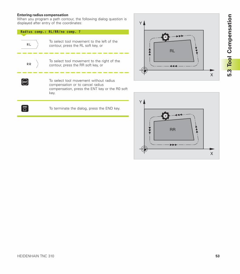
Entering radius compensationWhen you program a path contour, the following dialog question isdisplayed after entry of the coordinates:
Radius comp.: RL/RR/no comp. ?<
To select tool movement to the left of thecontour, press the RL soft key, or
To select tool movement to the right of thecontour, press the RR soft key, or
To select tool movement without radiuscompensation or to cancel radiuscompensation, press the ENT key or the R0 softkey.
To terminate the dialog, press the END key.
5.3
To
ol
Co
mp
en
sa
tio
n
X
Y
RL
X
Y
RR
54 5 Programming: Tools
5.3
To
ol
Co
mp
en
sa
tio
n
RL
RL RL
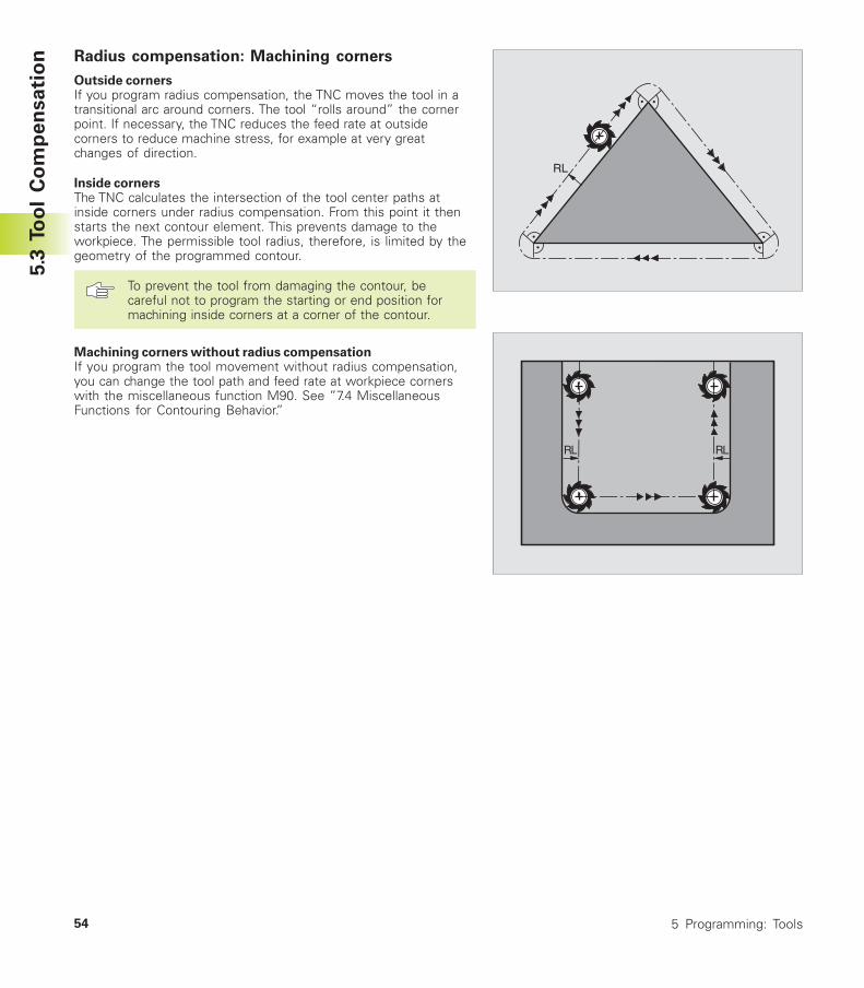
Radius compensation: Machining corners
Outside cornersIf you program radius compensation, the TNC moves the tool in atransitional arc around corners. The tool “rolls around” the cornerpoint. If necessary, the TNC reduces the feed rate at outsidecorners to reduce machine stress, for example at very greatchanges of direction.
Inside cornersThe TNC calculates the intersection of the tool center paths atinside corners under radius compensation. From this point it thenstarts the next contour element. This prevents damage to theworkpiece. The permissible tool radius, therefore, is limited by thegeometry of the programmed contour.
To prevent the tool from damaging the contour, becareful not to program the starting or end position formachining inside corners at a corner of the contour.
Machining corners without radius compensationIf you program the tool movement without radius compensation,you can change the tool path and feed rate at workpiece cornerswith the miscellaneous function M90. See ”7.4 MiscellaneousFunctions for Contouring Behavior.”

Programming:
Programming Contours
6
56 6 Programming: Programming Contours
6.1
Overv
iew
of
To
ol
Mo
vem
en
ts 6.1 Overview of Tool Movements
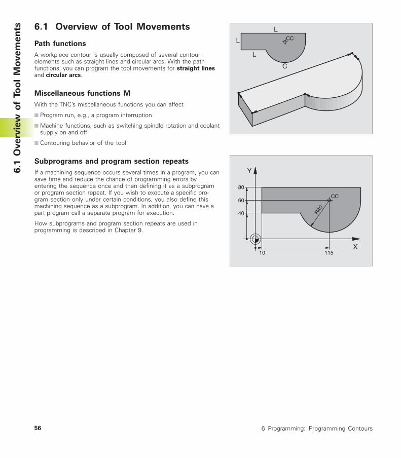
Path functions
A workpiece contour is usually composed of several contourelements such as straight lines and circular arcs. With the pathfunctions, you can program the tool movements for straight linesand circular arcs.
Miscellaneous functions M
With the TNC’s miscellaneous functions you can affect
■ Program run, e.g., a program interruption
■ Machine functions, such as switching spindle rotation and coolantsupply on and off
■ Contouring behavior of the tool
Subprograms and program section repeats
If a machining sequence occurs several times in a program, you cansave time and reduce the chance of programming errors byentering the sequence once and then defining it as a subprogramor program section repeat. If you wish to execute a specific pro-gram section only under certain conditions, you also define thismachining sequence as a subprogram. In addition, you can have apart program call a separate program for execution.
How subprograms and program section repeats are used inprogramming is described in Chapter 9.
L
L
L CC
C
X
Y
R40
11510
80
60
40
CC
57HEIDENHAIN TNC 310
6.2
Fu
nd
am
en
tals
of
Pa
th F
un
cti
on
s6.2 Fundamentals of Path Functions
Programming tool movements for workpiece
machining
You create a part program by programming the path functions forthe individual contour elements in sequence. You usually do this byentering the coordinates of the end points of the contourelements given in the production drawing. The TNC calculates theactual path of the tool from these coordinates, and from the tooldata and radius compensation.
The TNC moves all axes programmed in a single blocksimultaneously.
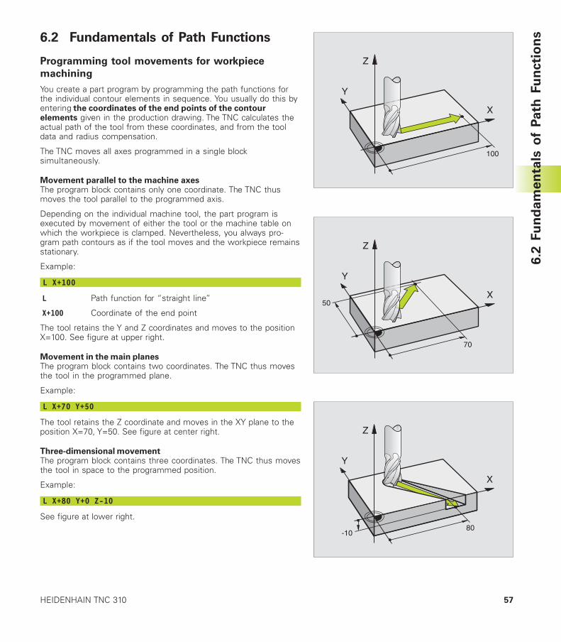
Movement parallel to the machine axesThe program block contains only one coordinate. The TNC thusmoves the tool parallel to the programmed axis.
Depending on the individual machine tool, the part program isexecuted by movement of either the tool or the machine table onwhich the workpiece is clamped. Nevertheless, you always pro-gram path contours as if the tool moves and the workpiece remainsstationary.
Example:
L X+100
L Path function for “straight line”
X+100 Coordinate of the end point
The tool retains the Y and Z coordinates and moves to the positionX=100. See figure at upper right.
Movement in the main planesThe program block contains two coordinates. The TNC thus movesthe tool in the programmed plane.
Example:
L X+70 Y+50
The tool retains the Z coordinate and moves in the XY plane to theposition X=70, Y=50. See figure at center right.
Three-dimensional movementThe program block contains three coordinates. The TNC thus movesthe tool in space to the programmed position.
Example:
L X+80 Y+0 Z-10
See figure at lower right.
X
Y
Z
100
X
Y
Z
70
50
X
Y
Z
80-10
58 6 Programming: Programming Contours
6.2
Fu
nd
am
en
tals
of
Pa
th F
un
cti
on
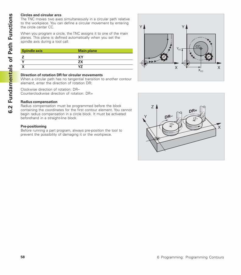
s Circles and circular arcsThe TNC moves two axes simultaneously in a circular path relativeto the workpiece. You can define a circular movement by enteringthe circle center CC.
When you program a circle, the TNC assigns it to one of the mainplanes. This plane is defined automatically when you set thespindle axis during a tool call:
Spindle axis Main plane
Z XY
Y ZX
X YZ
Direction of rotation DR for circular movementsWhen a circular path has no tangential transition to another contourelement, enter the direction of rotation DR:
Clockwise direction of rotation: DR–Counterclockwise direction of rotation: DR+
Radius compensationRadius compensation must be programmed before the blockcontaining the coordinates for the first contour element. You cannotbegin radius compensation in a circle block. It must be activatedbeforehand in a straight-line block.
Pre-positioningBefore running a part program, always pre-position the tool toprevent the possibility of damaging it or the workpiece.
X
Y
X
Y
CC
XCC
YCC
CC
CCDR–DR+
X
Z
Y
59HEIDENHAIN TNC 310
6.2
Fu
nd
am
en
tals
of
Pa
th F
un
cti
on
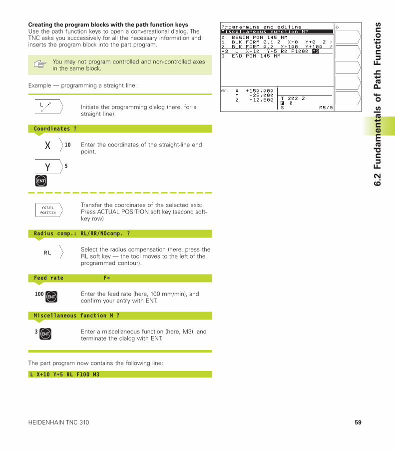
sCreating the program blocks with the path function keysUse the path function keys to open a conversational dialog. TheTNC asks you successively for all the necessary information andinserts the program block into the part program.
You may not program controlled and non-controlled axesin the same block.
Example — programming a straight line:
Initiate the programming dialog (here, for astraight line).
Coordinates ?<
10 Enter the coordinates of the straight-line endpoint.
5
Transfer the coordinates of the selected axis:Press ACTUAL POSITION soft key (second soft-key row)
Radius comp.: RL/RR/NOcomp. ?<
Select the radius compensation (here, press theRL soft key — the tool moves to the left of theprogrammed contour).
Feed rate F=<
100 Enter the feed rate (here, 100 mm/min), andconfirm your entry with ENT.
Miscellaneous function M ?<
3 Enter a miscellaneous function (here, M3), andterminate the dialog with ENT.
The part program now contains the following line:
L X+10 Y+5 RL F100 M3
60 6 Programming: Programming Contours
6.3 Contour Approach and Departure
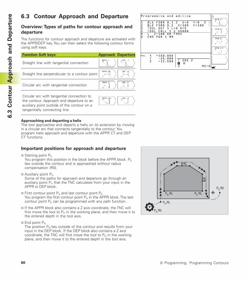
Overview: Types of paths for contour approach and
departure
The functions for contour approach and departure are activated withthe APPR/DEP key. You can then select the following contour formsusing soft keys.
Function Soft keys: Approach Departure
Straight line with tangential connection
Straight line perpendicular to a contour point
Circular arc with tangential connection
Circular arc with tangential connection tothe contour. Approach and departure to anauxiliary point outside of the contour on atangentially connecting line.
Approaching and departing a helixThe tool approaches and departs a helix on its extension by movingin a circular arc that connects tangentially to the contour. Youprogram helix approach and departure with the APPR CT and DEPCT functions.
Important positions for approach and departure
■ Starting point PSYou program this position in the block before the APPR block. PSlies outside the contour and is approached without radiuscompensation (R0).
■ Auxiliary point PHSome of the paths for approach and departure go through anauxiliary point PH that the TNC calculates from your input in theAPPR or DEP block.
■ First contour point PA and last contour point PEYou program the first contour point PA in the APPR block. The lastcontour point PE can be programmed with any path function.
■ If the APPR block also contains a Z axis coordinate, the TNC willfirst move the tool to PH in the working plane, and then move it tothe entered depth in the tool axis.
■ End point PNThe position PN lies outside of the contour and results from yourinput in the DEP block. If the DEP block also contains a Z axiscoordinate, the TNC will first move the tool to PH in the workingplane, and then move it to the entered depth in the tool axis.
PH RL
PS R0
PA RL PE RL
RL
RL
PN R0
6.3
Co
nto
ur
Ap
pro
ach
an
d D
ep
art
ure
61HEIDENHAIN TNC 310
You can enter the position data in absolute or incrementalcoordinates and in Cartesian or polar coordinates.
The TNC does not check whether the programmed contour will bedamaged when moving from the actual position to the auxiliarypoint PH. Use the test graphics to simulate approach and departurebefore executing the part program.
When approaching the contour, allow sufficient distance betweenthe starting point PS and the first contour point PA to assure that theTNC will reach the programmed feed rate for machining.
The TNC moves the tool from the actual position to the auxiliarypoint PH at the feed rate that was last programmed.
Radius compensationFor the TNC to interpret an APPR block as an approach block youmust program a change in compensation from R0 to RL/RR. TheTNC automatically cancels the radius compensation in a DEP block.If you wish to program a contour element with the DEP block (nochange in compensation), then you need to program the activeradius compensation again (2nd soft-key row, if the F element ishighlighted).
If no change in compensation is programmed in an APPR or in aDEP block, the TNC makes the contour connection as follows:
Function Contour connection
APPR LT Tangential connection to the followingContour element
APPR LN Perpendicular connection to the followingContour element
APPR CT without angle of traverse/without radius:
Tangentially connecting circular arc between thepreceding and the following contour element.without angle of traverse/with radius:
Tangentially connecting circular arc with programmedradius to the following contour elementwith angle of traverse/without radius:
Tangentially connecting circular are with angle oftraverse to the following contour elementwith angle of traverse/with radius:
Tangentially connecting circular arc with connectingline and angle of traverse to the following contourelement
APPR LCT Tangent with connecting tangentialcircular arc to the following contour element
Abbreviation Meaning
APPR ApproachDEP DepartureL LineC CircleT Tangential
(smooth connection)N Normal (perpendicular)
6.3
Co
nto
ur
Ap
pro
ach
an
d D
ep
art
ure
Function Contour connection
DEP LT Tangential connection to thepreceding contour element
DEP LN Perpendicular connection to thepreceding contour element
DEP CT without angle of traverse/without
radius:
Tangentially connecting circular arcbetween the preceding and thefollowing Contour elementwithout angle of traverse/with
radius:
Tangentially connecting circular arcwith programmed radius to thepreceding contour elementwith angle of traverse/without
radius:
Tangentially connecting circular arcwith angle of traverse to thepreceding contour elementwith angle of traverse/with radius:
Tangentially connecting circular arcwith connecting line and angle oftraverse to the preceding contourelement
DEP LCT Tangent with tangentiallyconnecting circular arc to thepreceding contour element
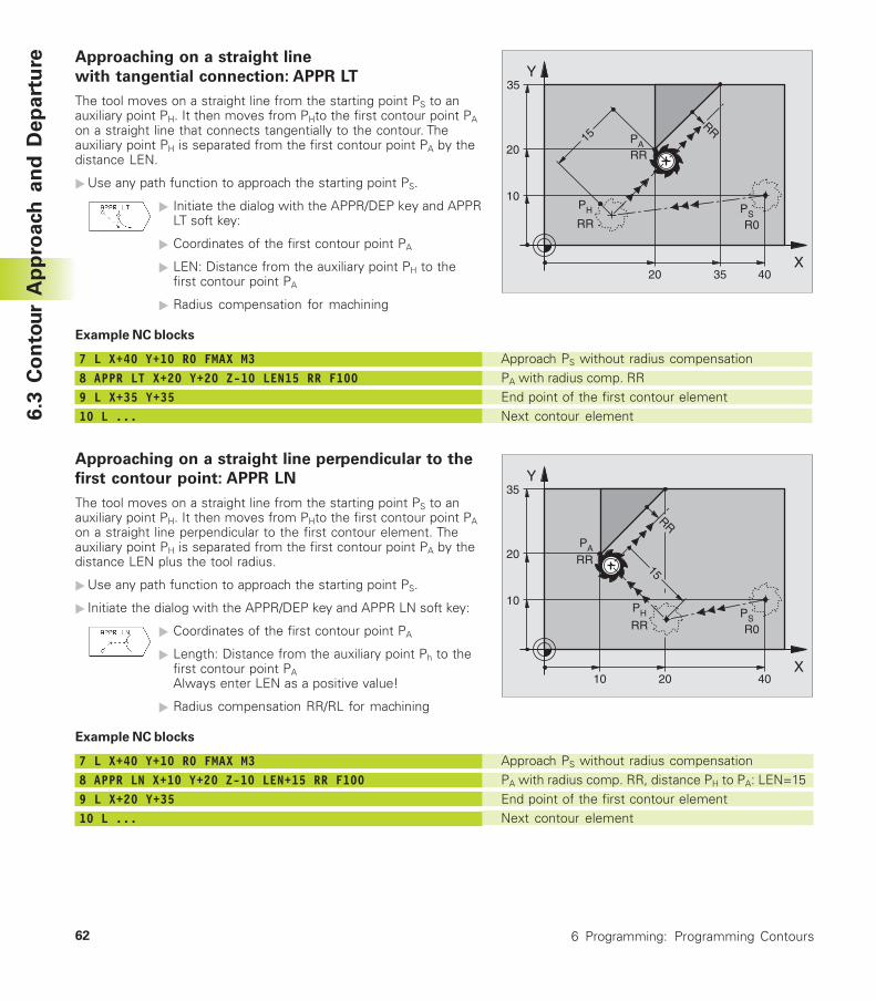
62 6 Programming: Programming Contours
Approach PS without radius compensationPA with radius comp. RR, distance PH to PA: LEN=15End point of the first contour elementNext contour element
X
Y
10
10
20 PA RR
PS
R0
PH
RR
RR
40
15
35
20
Approach PS without radius compensationPA with radius comp. RREnd point of the first contour elementNext contour element
X
Y
20
10
20PA RR
PS
R0
15
PH
RR
RR
40
35
35
Approaching on a straight line
with tangential connection: APPR LT
The tool moves on a straight line from the starting point PS to anauxiliary point PH. It then moves from PHto the first contour point PAon a straight line that connects tangentially to the contour. Theauxiliary point PH is separated from the first contour point PA by thedistance LEN.
�Use any path function to approach the starting point PS.
� Initiate the dialog with the APPR/DEP key and APPRLT soft key:
� Coordinates of the first contour point PA
� LEN: Distance from the auxiliary point PH to thefirst contour point PA
� Radius compensation for machining
Example NC blocks
7 L X+40 Y+10 R0 FMAX M38 APPR LT X+20 Y+20 Z-10 LEN15 RR F1009 L X+35 Y+3510 L ...
Approaching on a straight line perpendicular to the
first contour point: APPR LN
The tool moves on a straight line from the starting point PS to anauxiliary point PH. It then moves from PHto the first contour point PAon a straight line perpendicular to the first contour element. Theauxiliary point PH is separated from the first contour point PA by thedistance LEN plus the tool radius.
�Use any path function to approach the starting point PS.
� Initiate the dialog with the APPR/DEP key and APPR LN soft key:
� Coordinates of the first contour point PA
� Length: Distance from the auxiliary point Ph to thefirst contour point PAAlways enter LEN as a positive value!
� Radius compensation RR/RL for machining
Example NC blocks
7 L X+40 Y+10 R0 FMAX M38 APPR LN X+10 Y+20 Z-10 LEN+15 RR F1009 L X+20 Y+3510 L ...
6.3
Co
nto
ur
Ap
pro
ach
an
d D
ep
art
ure
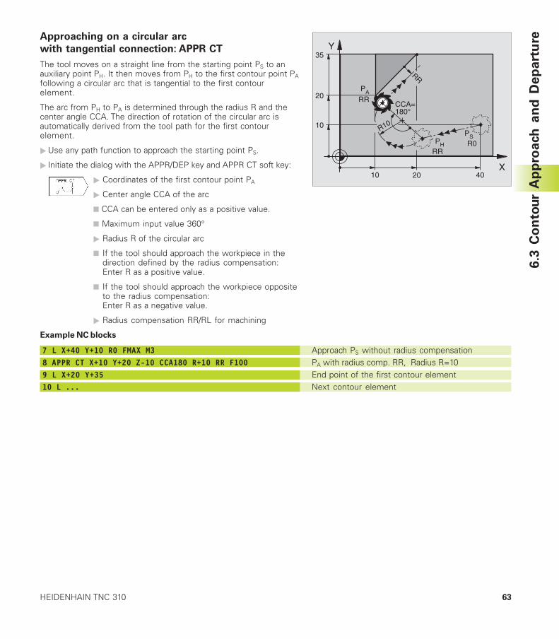
63HEIDENHAIN TNC 310
X
Y
10
20 PARR
PS
R0 PHRR
RR
4010
CCA=180°
R10
35
20
Approach PS without radius compensationPA with radius comp. RR, Radius R=10End point of the first contour elementNext contour element
Approaching on a circular arc
with tangential connection: APPR CT
The tool moves on a straight line from the starting point PS to anauxiliary point PH. It then moves from PH to the first contour point PAfollowing a circular arc that is tangential to the first contourelement.
The arc from PH to PA is determined through the radius R and thecenter angle CCA. The direction of rotation of the circular arc isautomatically derived from the tool path for the first contourelement.
�Use any path function to approach the starting point PS.
� Initiate the dialog with the APPR/DEP key and APPR CT soft key:
� Coordinates of the first contour point PA
� Center angle CCA of the arc
■ CCA can be entered only as a positive value.
■ Maximum input value 360°
� Radius R of the circular arc
■ If the tool should approach the workpiece in thedirection defined by the radius compensation:Enter R as a positive value.
■ If the tool should approach the workpiece oppositeto the radius compensation:Enter R as a negative value.
� Radius compensation RR/RL for machining
Example NC blocks
7 L X+40 Y+10 R0 FMAX M38 APPR CT X+10 Y+20 Z-10 CCA180 R+10 RR F1009 L X+20 Y+3510 L ...
6.3
Co
nto
ur
Ap
pro
ach
an
d D
ep
art
ure
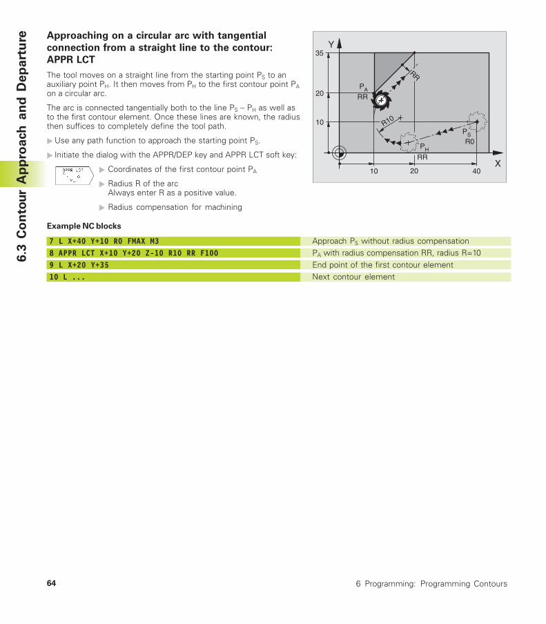
64 6 Programming: Programming Contours
Approaching on a circular arc with tangential
connection from a straight line to the contour:
APPR LCT
The tool moves on a straight line from the starting point PS to anauxiliary point PH. It then moves from PH to the first contour point PAon a circular arc.
The arc is connected tangentially both to the line PS – PH as well asto the first contour element. Once these lines are known, the radiusthen suffices to completely define the tool path.
�Use any path function to approach the starting point PS.
� Initiate the dialog with the APPR/DEP key and APPR LCT soft key:
� Coordinates of the first contour point PA
� Radius R of the arcAlways enter R as a positive value.
� Radius compensation for machining
Example NC blocks
7 L X+40 Y+10 R0 FMAX M38 APPR LCT X+10 Y+20 Z-10 R10 RR F1009 L X+20 Y+3510 L ...
Approach PS without radius compensationPA with radius compensation RR, radius R=10End point of the first contour elementNext contour element
X
Y
10
20 PA RR
PS
R0 PH
RR
RR
4010
R10
35
20
6.3
Co
nto
ur
Ap
pro
ach
an
d D
ep
art
ure
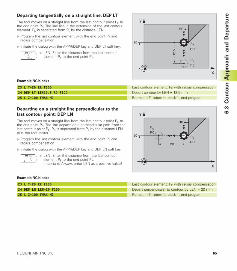
65HEIDENHAIN TNC 310
Departing tangentially on a straight line: DEP LT
The tool moves on a straight line from the last contour point PE tothe end point PN. The line lies in the extension of the last contourelement. PN is separated from PE by the distance LEN.
�Program the last contour element with the end point PE andradius compensation.
� Initiate the dialog with the APPR/DEP key and DEP LT soft key:
� LEN: Enter the distance from the last contourelement PE to the end point PN.
Example NC blocks
23 L Y+20 RR F10024 DEP LT LEN12.5 R0 F10025 L Z+100 FMAX M2
Departing on a straight line perpendicular to the
last contour point: DEP LN
The tool moves on a straight line from the last contour point PE tothe end point PN. The line departs on a perpendicular path from thelast contour point PE. PN is separated from PE by the distance LENplus the tool radius.
�Program the last contour element with the end point PE andradius compensation.
� Initiate the dialog with the APPR/DEP key and DEP LN soft key:
� LEN: Enter the distance from the last contourelement PE to the end point PN.Important: Always enter LEN as a positive value!
Example NC blocks
23 L Y+20 RR F10024 DEP LN LEN+20 F10025 L Z+100 FMAX M2
Last contour element: PE with radius compensationDepart contour by LEN = 12.5 mmRetract in Z, return to block 1, end program
Last contour element: PE with radius compensationDepart perpendicular to contour by LEN = 20 mmRetract in Z, return to block 1, end program
X
Y
20 PE RR
PN
R0
RR
12.5
X
Y
20 PE RR
PN
R0
RR
20
6.3
Co
nto
ur
Ap
pro
ach
an
d D
ep
art
ure
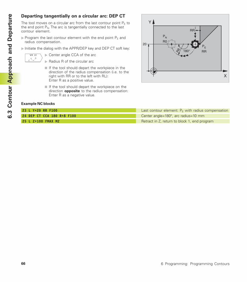
66 6 Programming: Programming Contours
Last contour element: PE with radius compensationCenter angle=180°, arc radius=10 mmRetract in Z, return to block 1, end program
X
Y
20
PN R0
PE
RRR8 180°
RR
Departing tangentially on a circular arc: DEP CT
The tool moves on a circular arc from the last contour point PE tothe end point PN. The arc is tangentially connected to the lastcontour element.
�Program the last contour element with the end point PE andradius compensation.
� Initiate the dialog with the APPR/DEP key and DEP CT soft key:
� Center angle CCA of the arc
� Radius R of the circular arc
■ If the tool should depart the workpiece in thedirection of the radius compensation (i.e. to theright with RR or to the left with RL):Enter R as a positive value.
■ If the tool should depart the workpiece on thedirection opposite to the radius compensation:Enter R as a negative value.
Example NC blocks
23 L Y+20 RR F10024 DEP CT CCA 180 R+8 F10025 L Z+100 FMAX M2
6.3
Co
nto
ur
Ap
pro
ach
an
d D
ep
art
ure
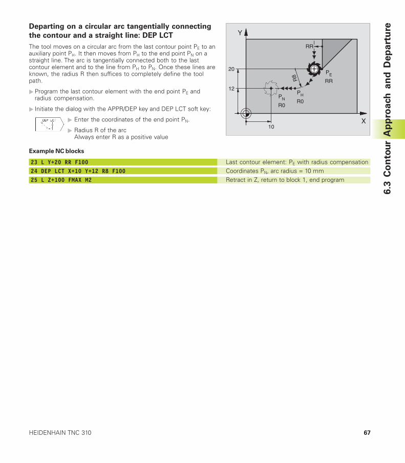
67HEIDENHAIN TNC 310
Last contour element: PE with radius compensationCoordinates PN, arc radius = 10 mmRetract in Z, return to block 1, end program
X
Y
20
PN R0
PE
RR
RR
12
10
R8
PH R0
Departing on a circular arc tangentially connecting
the contour and a straight line: DEP LCT
The tool moves on a circular arc from the last contour point PE to anauxiliary point PH. It then moves from PH to the end point PN on astraight line. The arc is tangentially connected both to the lastcontour element and to the line from PH to PN. Once these lines areknown, the radius R then suffices to completely define the toolpath.
�Program the last contour element with the end point PE andradius compensation.
� Initiate the dialog with the APPR/DEP key and DEP LCT soft key:
� Enter the coordinates of the end point PN.
� Radius R of the arcAlways enter R as a positive value
Example NC blocks
23 L Y+20 RR F10024 DEP LCT X+10 Y+12 R8 F10025 L Z+100 FMAX M2
6.3
Co
nto
ur
Ap
pro
ach
an
d D
ep
art
ure
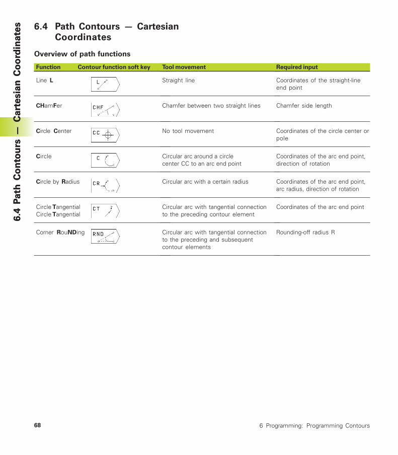
68 6 Programming: Programming Contours
6.4
Pa
th C
on
tou
rs —
Ca
rte
sia
n C
oo
rdin
ate
s 6.4 Path Contours — CartesianCoordinates
Overview of path functions
Function Contour function soft key
Line L
CHamFer
Circle Center
Circle
Circle by Radius
Circle TangentialCircle Tangential
Corner RouNDing
Tool movement
Straight line
Chamfer between two straight lines
No tool movement
Circular arc around a circlecenter CC to an arc end point
Circular arc with a certain radius
Circular arc with tangential connectionto the preceding contour element
Circular arc with tangential connectionto the preceding and subsequentcontour elements
Required input
Coordinates of the straight-lineend point
Chamfer side length
Coordinates of the circle center orpole
Coordinates of the arc end point,direction of rotation
Coordinates of the arc end point,arc radius, direction of rotation
Coordinates of the arc end point
Rounding-off radius R
6.4
Pa
th C
on
tou
rs —
Ca
rte
sia
n C
oo
rdin
ate
s
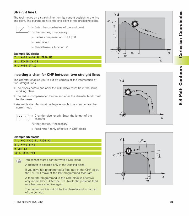
69HEIDENHAIN TNC 310
6.4
Pa
th C
on
tou
rs —
Ca
rte
sia
n C
oo
rdin
ate
sStraight line L
The tool moves on a straight line from its current position to the lineend point. The starting point is the end point of the preceding block.
� Enter the coordinates of the end point.
Further entries, if necessary:
� Radius compensation RL/RR/R0
� Feed rate F
� Miscellaneous function M
Example NC blocks
7 L X+10 Y+40 RL F200 M38 L IX+20 IY-159 L X+60 IY-10
Inserting a chamfer CHF between two straight lines
The chamfer enables you to cut off corners at the intersection oftwo straight lines.
■ The blocks before and after the CHF block must be in the sameworking plane.
■ The radius compensation before and after the chamfer block mustbe the same.
■ An inside chamfer must be large enough to accommodate thecurrent tool.
� Chamfer side length: Enter the length of thechamfer
Further entries, if necessary:
� Feed rate F (only effective in CHF block)
Example NC blocks
7 L X+0 Y+30 RL F300 M38 L X+40 IY+59 CHF 1210 L IX+5 Y+0
You cannot start a contour with a CHF block
A chamfer is possible only in the working plane.
If you have not programmed a feed rate in the CHF block,the TNC will move at the last programmed feed rate.
A feed rate programmed in the CHF block is effectiveonly in that block. After the CHF block, the previous feedrate becomes effective again.
The corner point is cut off by the chamfer and is not partof the contour.
X
Y
60
15
40
10
1020
X
Y
6.4
Pa
th C
on
tou
rs —
Ca
rte
sia
n C
oo
rdin
ate
sX
Y
40
1230
5
12
5
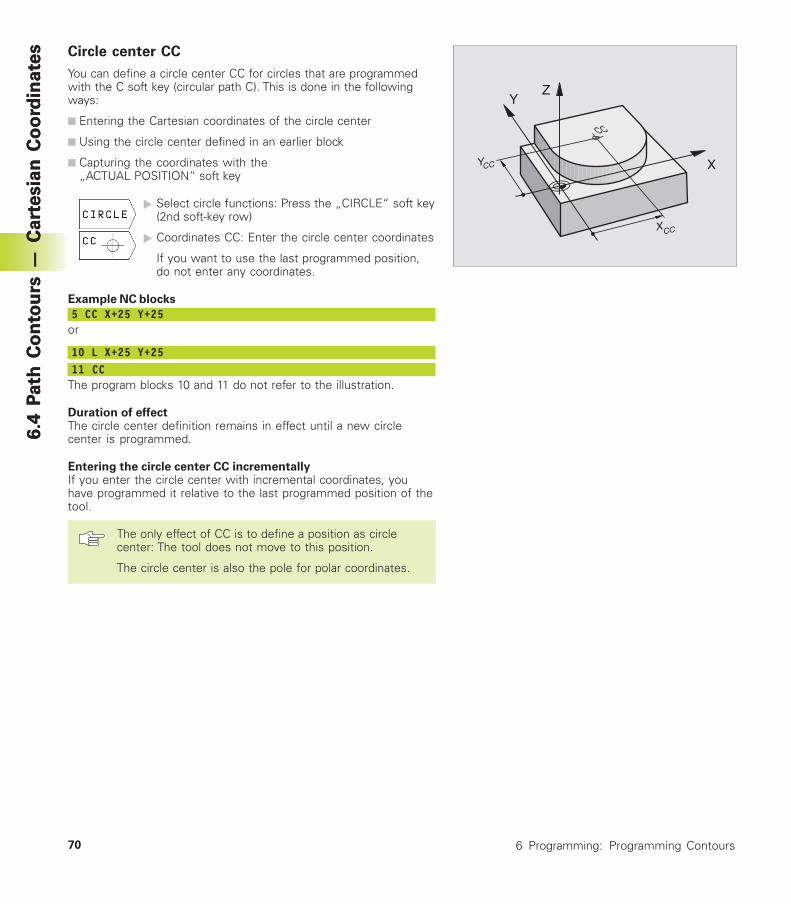
70 6 Programming: Programming Contours
6.4
Pa
th C
on
tou
rs —
Ca
rte
sia
n C
oo
rdin
ate
s
CC
ZY
X
XCC
YCC
Circle center CC
You can define a circle center CC for circles that are programmedwith the C soft key (circular path C). This is done in the followingways:
■ Entering the Cartesian coordinates of the circle center
■ Using the circle center defined in an earlier block
■ Capturing the coordinates with the„ACTUAL POSITION“ soft key
� Select circle functions: Press the „CIRCLE“ soft key(2nd soft-key row)
� Coordinates CC: Enter the circle center coordinates
If you want to use the last programmed position,do not enter any coordinates.
Example NC blocks
5 CC X+25 Y+25or
10 L X+25 Y+2511 CC
The program blocks 10 and 11 do not refer to the illustration.
Duration of effectThe circle center definition remains in effect until a new circlecenter is programmed.
Entering the circle center CC incrementallyIf you enter the circle center with incremental coordinates, youhave programmed it relative to the last programmed position of thetool.
The only effect of CC is to define a position as circlecenter: The tool does not move to this position.
The circle center is also the pole for polar coordinates.
6.4
Pa
th C
on
tou
rs —
Ca
rte
sia
n C
oo
rdin
ate
s
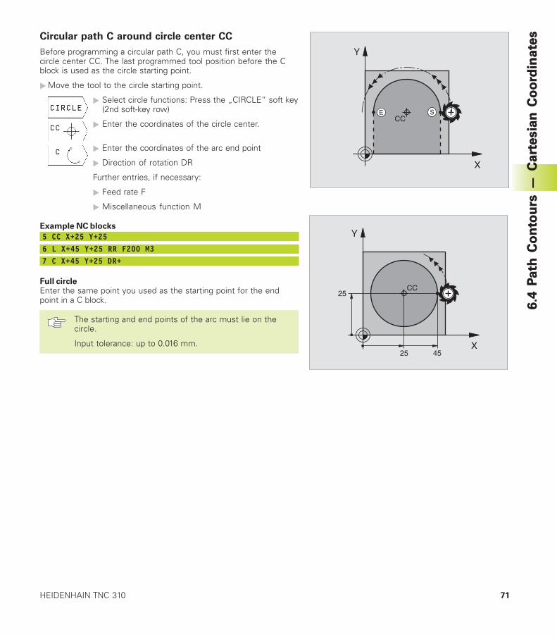
71HEIDENHAIN TNC 310
6.4
Pa
th C
on
tou
rs —
Ca
rte
sia
n C
oo
rdin
ate
sCircular path C around circle center CC
Before programming a circular path C, you must first enter thecircle center CC. The last programmed tool position before the Cblock is used as the circle starting point.
�Move the tool to the circle starting point.
� Select circle functions: Press the „CIRCLE“ soft key(2nd soft-key row)
� Enter the coordinates of the circle center.
� Enter the coordinates of the arc end point
� Direction of rotation DR
Further entries, if necessary:
� Feed rate F
� Miscellaneous function M
Example NC blocks
5 CC X+25 Y+256 L X+45 Y+25 RR F200 M37 C X+45 Y+25 DR+
Full circleEnter the same point you used as the starting point for the endpoint in a C block.
The starting and end points of the arc must lie on thecircle.
Input tolerance: up to 0.016 mm. X
Y
25 45
25CC
SE
X
Y
CC
6.4
Pa
th C
on
tou
rs —
Ca
rte
sia
n C
oo
rdin
ate
s
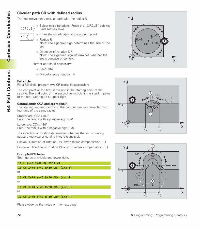
72 6 Programming: Programming Contours
6.4
Pa
th C
on
tou
rs —
Ca
rte
sia
n C
oo
rdin
ate
s Circular path CR with defined radius
The tool moves on a circular path with the radius R.
� Select circle functions: Press the „CIRCLE“ soft key(2nd soft-key row)
� Enter the coordinates of the arc end point.
� Radius RNote: The algebraic sign determines the size of thearc.
� Direction of rotation DRNote: The algebraic sign determines whether thearc is concave or convex.
Further entries, if necessary:
� Feed rate F
� Miscellaneous function M
Full circleFor a full circle, program two CR blocks in succession:
The end point of the first semicircle is the starting point of thesecond. The end point of the second semicircle is the starting pointof the first. See figure at upper right.
Central angle CCA and arc radius RThe starting and end points on the contour can be connected withfour arcs of the same radius:
Smaller arc: CCA<180°Enter the radius with a positive sign R>0
Larger arc: CCA>180°Enter the radius with a negative sign R<0
The direction of rotation determines whether the arc is curvingoutward (convex) or curving inward (concave):
Convex: Direction of rotation DR– (with radius compensation RL)
Concave: Direction of rotation DR+ (with radius compensation RL)
Example NC blocksSee figures at middle and lower right.
10 L X+40 Y+40 RL F200 M311 CR X+70 Y+40 R+20 DR– (arc 1)
or
11 CR X+70 Y+40 R+20 DR+ (arc 2)or
11 CR X+70 Y+40 R-20 DR- (arc 3)or
11 CR X+70 Y+40 R-20 DR+ (arc 4)
Please observe the notes on the next page!
X
Y
ZWRR
40
40 70
1
2
DR+
X
Y
40
40 70
DR+
4
ZW
3
R R
X
Y
CC S1=E2
E1=S2
R
6.4
Pa
th C
on
tou
rs —
Ca
rte
sia
n C
oo
rdin
ate
s
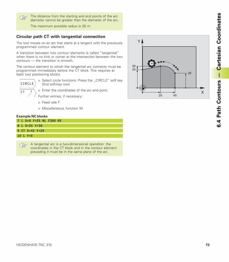
73HEIDENHAIN TNC 310
6.4
Pa
th C
on
tou
rs —
Ca
rte
sia
n C
oo
rdin
ate
sThe distance from the starting and end points of the arcdiameter cannot be greater than the diameter of the arc.
The maximum possible radius is 30 m.
Circular path CT with tangential connection
The tool moves on an arc that starts at a tangent with the previouslyprogrammed contour element.
A transition between two contour elements is called “tangential”when there is no kink or corner at the intersection between the twocontours — the transition is smooth.
The contour element to which the tangential arc connects must beprogrammed immediately before the CT block. This requires atleast two positioning blocks.
� Select circle functions: Press the „CIRCLE“ soft key(2nd soft-key row)
� Enter the coordinates of the arc end point.
Further entries, if necessary:
� Feed rate F
� Miscellaneous function M
Example NC blocks
7 L X+0 Y+25 RL F300 M38 L X+25 Y+309 CT X+45 Y+2010 L Y+0
A tangential arc is a two-dimensional operation: thecoordinates in the CT block and in the contour elementpreceding it must be in the same plane of the arc.
X
Y
25 45
2530
20
6.4
Pa
th C
on
tou
rs —
Ca
rte
sia
n C
oo
rdin
ate
s
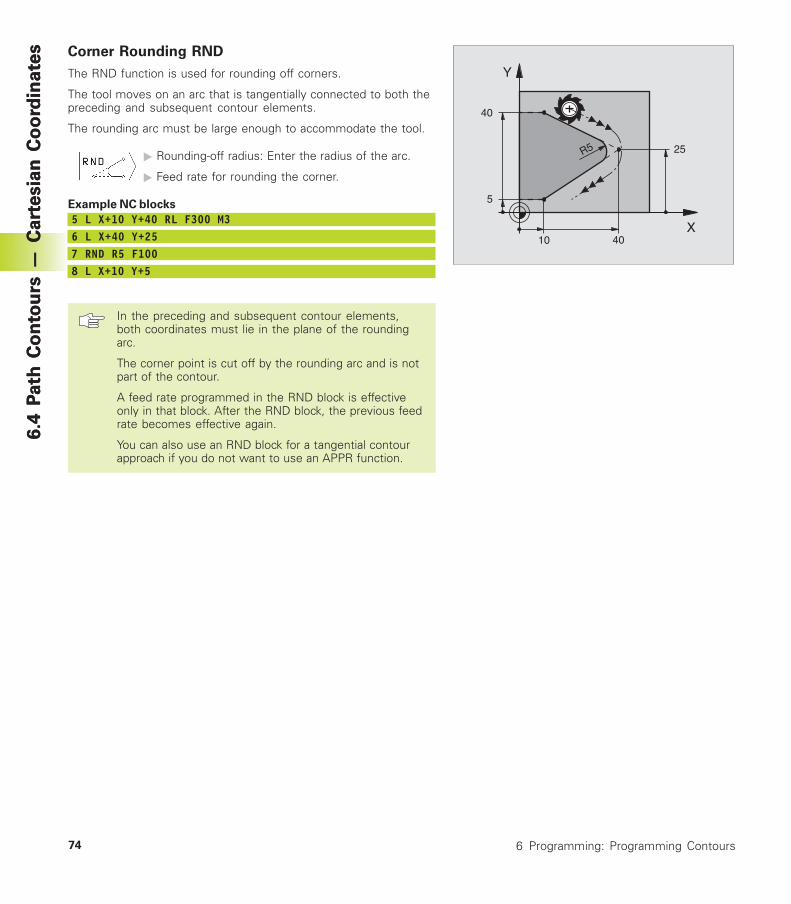
74 6 Programming: Programming Contours
6.4
Pa
th C
on
tou
rs —
Ca
rte
sia
n C
oo
rdin
ate
s Corner Rounding RND
The RND function is used for rounding off corners.
The tool moves on an arc that is tangentially connected to both thepreceding and subsequent contour elements.
The rounding arc must be large enough to accommodate the tool.
� Rounding-off radius: Enter the radius of the arc.
� Feed rate for rounding the corner.
Example NC blocks
5 L X+10 Y+40 RL F300 M36 L X+40 Y+257 RND R5 F1008 L X+10 Y+5
In the preceding and subsequent contour elements,both coordinates must lie in the plane of the roundingarc.
The corner point is cut off by the rounding arc and is notpart of the contour.
A feed rate programmed in the RND block is effectiveonly in that block. After the RND block, the previous feedrate becomes effective again.
You can also use an RND block for a tangential contourapproach if you do not want to use an APPR function.
X
Y
40
40
R5
5
10
25
6.4
Pa
th C
on
tou
rs —
Ca
rte
sia
n C
oo
rdin
ate
s
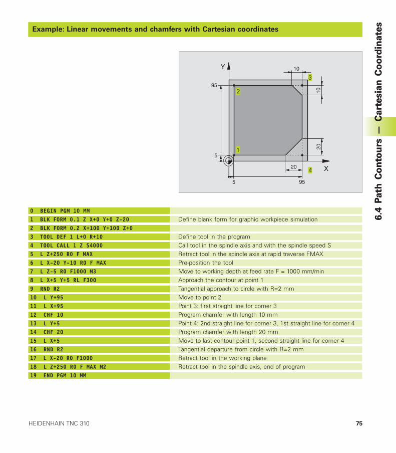
75HEIDENHAIN TNC 310
6.4
Pa
th C
on
tou
rs —
Ca
rte
sia
n C
oo
rdin
ate
s
Example: Linear movements and chamfers with Cartesian coordinates
6.4
Pa
th C
on
tou
rs —
Ca
rte
sia
n C
oo
rdin
ate
s
Example: Linear movements and chamfers with Cartesian coordinates
X
Y
955
95
5
10
10
20
20
0 BEGIN PGM 10 MM1 BLK FORM 0.1 Z X+0 Y+0 Z-202 BLK FORM 0.2 X+100 Y+100 Z+03 TOOL DEF 1 L+0 R+104 TOOL CALL 1 Z S40005 L Z+250 R0 F MAX6 L X-20 Y-10 R0 F MAX7 L Z-5 R0 F1000 M38 L X+5 Y+5 RL F3009 RND R210 L Y+9511 L X+9512 CHF 1013 L Y+514 CHF 2015 L X+516 RND R217 L X-20 R0 F100018 L Z+250 R0 F MAX M219 END PGM 10 MM
Define blank form for graphic workpiece simulation
Define tool in the programCall tool in the spindle axis and with the spindle speed SRetract tool in the spindle axis at rapid traverse FMAXPre-position the toolMove to working depth at feed rate F = 1000 mm/minApproach the contour at point 1Tangential approach to circle with R=2 mmMove to point 2Point 3: first straight line for corner 3Program chamfer with length 10 mmPoint 4: 2nd straight line for corner 3, 1st straight line for corner 4Program chamfer with length 20 mmMove to last contour point 1, second straight line for corner 4Tangential departure from circle with R=2 mmRetract tool in the working planeRetract tool in the spindle axis, end of program
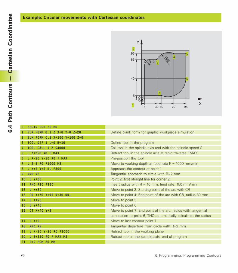
76 6 Programming: Programming Contours
Example: Circular movements with Cartesian coordinates
6.4
Pa
th C
on
tou
rs —
Ca
rte
sia
n C
oo
rdin
ate
s
Example: Circular movements with Cartesian coordinates
0 BEGIN PGM 20 MM1 BLK FORM 0.1 Z X+0 Y+0 Z-202 BLK FORM 0.2 X+100 Y+100 Z+03 TOOL DEF 1 L+0 R+104 TOOL CALL 1 Z S40005 L Z+250 R0 F MAX6 L X-20 Y-20 R0 F MAX7 L Z-5 R0 F1000 M38 L X+5 Y+5 RL F3009 RND R210 L Y+8511 RND R10 F15012 L X+3013 CR X+70 Y+95 R+30 DR-14 L X+9515 L Y+4016 CT X+40 Y+5
17 L X+518 RND R219 L X-20 Y-20 R0 F100020 L Z+250 R0 F MAX M221 END PGM 20 MM
Define blank form for graphic workpiece simulation
Define tool in the programCall tool in the spindle axis and with the spindle speed SRetract tool in the spindle axis at rapid traverse FMAXPre-position the toolMove to working depth at feed rate F = 1000 mm/minApproach the contour at point 1Tangential approach to circle with R=2 mmPoint 2: first straight line for corner 2Insert radius with R = 10 mm, feed rate: 150 mm/minMove to point 3: Starting point of the arc with CRMove to point 4: End point of the arc with CR, radius 30 mmMove to point 5Move to point 6Move to point 7: End point of the arc, radius with tangentialconnection to point 6, TNC automatically calculates the radiusMove to last contour point 1Tangential departure from circle with R=2 mmRetract tool in the working planeRetract tool in the spindle axis, end of program
X
Y
955
95
5
85
40
4030 70
R10
R30
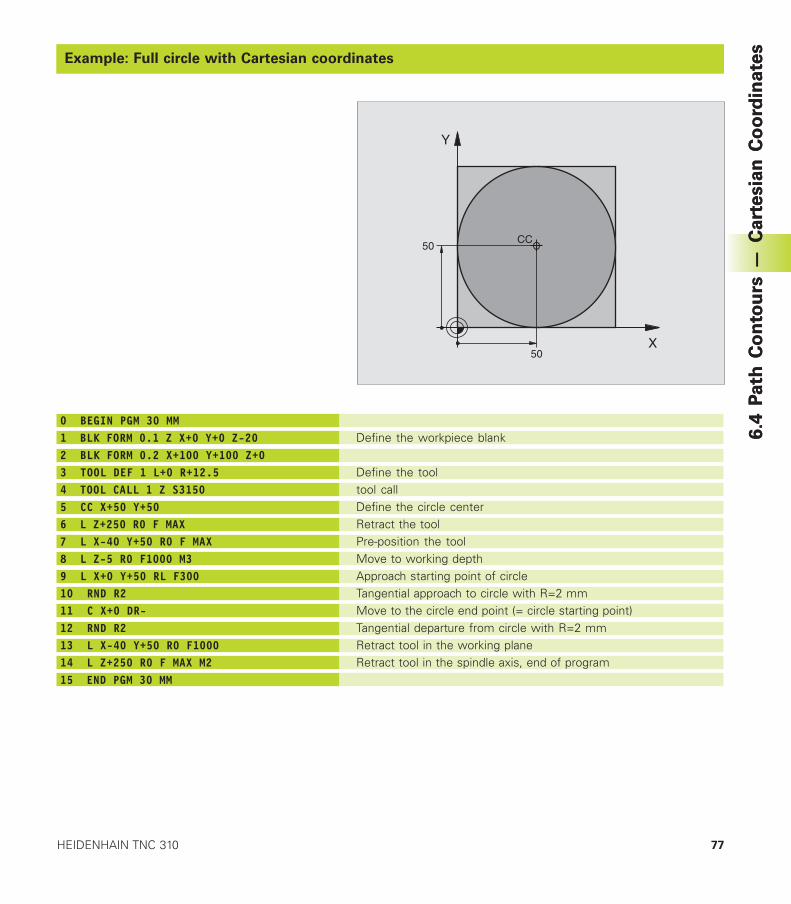
77HEIDENHAIN TNC 310
6.4
Pa
th C
on
tou
rs —
Ca
rte
sia
n C
oo
rdin
ate
s
Example: Full circle with Cartesian coordinates
6.4
Pa
th C
on
tou
rs —
Ca
rte
sia
n C
oo
rdin
ate
s
Example: Full circle with Cartesian coordinates
0 BEGIN PGM 30 MM1 BLK FORM 0.1 Z X+0 Y+0 Z-202 BLK FORM 0.2 X+100 Y+100 Z+03 TOOL DEF 1 L+0 R+12.54 TOOL CALL 1 Z S31505 CC X+50 Y+506 L Z+250 R0 F MAX7 L X-40 Y+50 R0 F MAX8 L Z-5 R0 F1000 M39 L X+0 Y+50 RL F30010 RND R211 C X+0 DR-12 RND R213 L X-40 Y+50 R0 F100014 L Z+250 R0 F MAX M215 END PGM 30 MM
Define the workpiece blank
Define the tooltool callDefine the circle centerRetract the toolPre-position the toolMove to working depthApproach starting point of circleTangential approach to circle with R=2 mmMove to the circle end point (= circle starting point)Tangential departure from circle with R=2 mmRetract tool in the working planeRetract tool in the spindle axis, end of program
X
Y
50
50CC
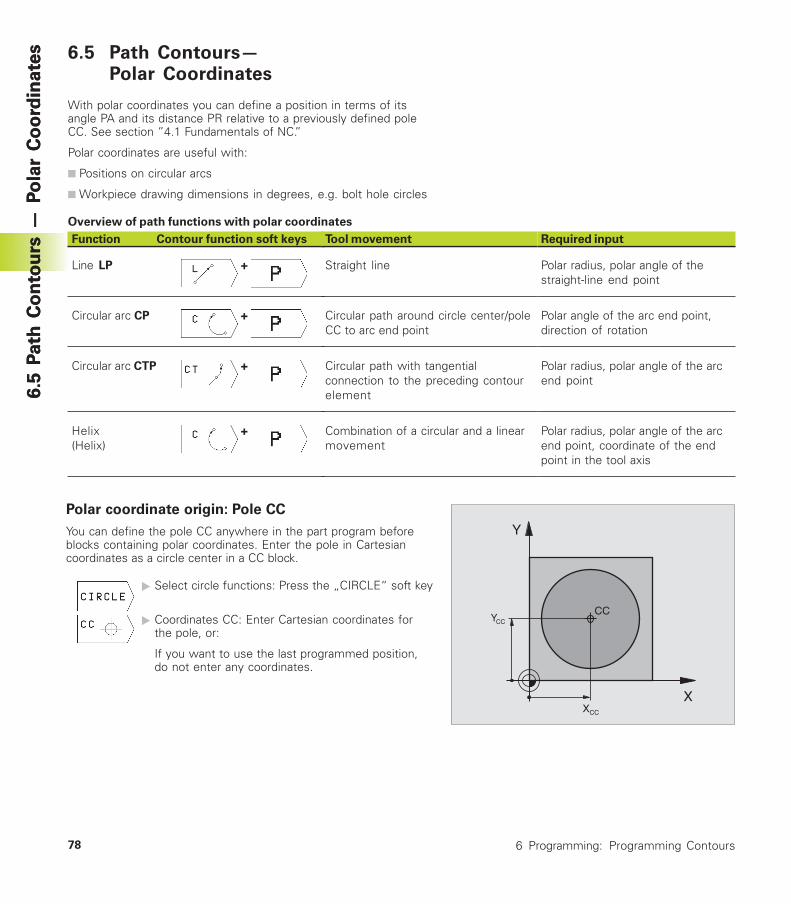
78 6 Programming: Programming Contours
6.5
Path
Co
nto
urs
— P
ola
r C
oo
rdin
ate
s6.5
Path
Co
nto
urs
— P
ola
r C
oo
rdin
ate
s 6.5 Path Contours—Polar Coordinates
With polar coordinates you can define a position in terms of itsangle PA and its distance PR relative to a previously defined poleCC. See section ”4.1 Fundamentals of NC.”
Polar coordinates are useful with:
■ Positions on circular arcs
■ Workpiece drawing dimensions in degrees, e.g. bolt hole circles
Overview of path functions with polar coordinates
Polar coordinate origin: Pole CC
You can define the pole CC anywhere in the part program beforeblocks containing polar coordinates. Enter the pole in Cartesiancoordinates as a circle center in a CC block.
� Select circle functions: Press the „CIRCLE“ soft key
� Coordinates CC: Enter Cartesian coordinates forthe pole, or:
If you want to use the last programmed position,do not enter any coordinates.
X
Y
CC
XCC
YCC
Function Contour function soft keys
Line LP +
Circular arc CP +
Circular arc CTP +
Helix +
(Helix)
Tool movement
Straight line
Circular path around circle center/poleCC to arc end point
Circular path with tangentialconnection to the preceding contourelement
Combination of a circular and a linearmovement
Required input
Polar radius, polar angle of thestraight-line end point
Polar angle of the arc end point,direction of rotation
Polar radius, polar angle of the arcend point
Polar radius, polar angle of the arcend point, coordinate of the endpoint in the tool axis
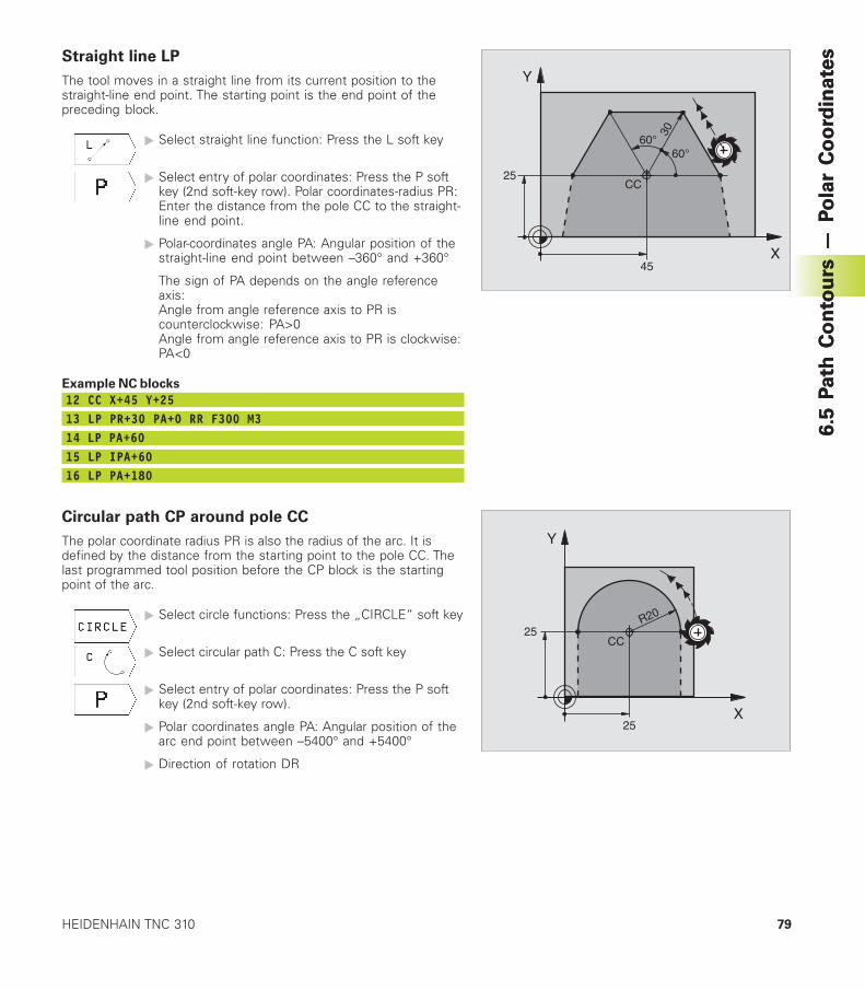
79HEIDENHAIN TNC 310
6.5
Path
Co
nto
urs
— P
ola
r C
oo
rdin
ate
sStraight line LP
The tool moves in a straight line from its current position to thestraight-line end point. The starting point is the end point of thepreceding block.
� Select straight line function: Press the L soft key
� Select entry of polar coordinates: Press the P softkey (2nd soft-key row). Polar coordinates-radius PR:Enter the distance from the pole CC to the straight-line end point.
� Polar-coordinates angle PA: Angular position of thestraight-line end point between –360° and +360°
The sign of PA depends on the angle referenceaxis:Angle from angle reference axis to PR iscounterclockwise: PA>0Angle from angle reference axis to PR is clockwise:PA<0
Example NC blocks
12 CC X+45 Y+2513 LP PR+30 PA+0 RR F300 M314 LP PA+6015 LP IPA+6016 LP PA+180
Circular path CP around pole CC
The polar coordinate radius PR is also the radius of the arc. It isdefined by the distance from the starting point to the pole CC. Thelast programmed tool position before the CP block is the startingpoint of the arc.
� Select circle functions: Press the „CIRCLE“ soft key
� Select circular path C: Press the C soft key
� Select entry of polar coordinates: Press the P softkey (2nd soft-key row).
� Polar coordinates angle PA: Angular position of thearc end point between –5400° and +5400°
� Direction of rotation DR
X
Y
45
25
60°60°
30
CC
X
Y
25
25R20
CC
6.5
Path
Co
nto
urs
— P
ola
r C
oo
rdin
ate
s
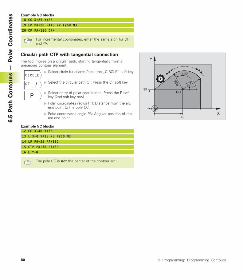
80 6 Programming: Programming Contours
6.5
Path
Co
nto
urs
— P
ola
r C
oo
rdin
ate
s6.5
Path
Co
nto
urs
— P
ola
r C
oo
rdin
ate
s Example NC blocks
18 CC X+25 Y+2519 LP PR+20 PA+0 RR F250 M320 CP PA+180 DR+
For incremental coordinates, enter the same sign for DRand PA.
Circular path CTP with tangential connection
The tool moves on a circular path, starting tangentially from apreceding contour element.
� Select circle functions: Press the „CIRCLE“ soft key
� Select the circular path CT: Press the CT soft key
� Select entry of polar coordinates: Press the P softkey (2nd soft-key row).
� Polar coordinates radius PR: Distance from the arcend point to the pole CC.
� Polar coordinates angle PA: Angular position of thearc end point.
Example NC blocks
12 CC X+40 Y+3513 L X+0 Y+35 RL F250 M314 LP PR+25 PA+12015 CTP PR+30 PA+3016 L Y+0
The pole CC is not the center of the contour arc!
X
Y
40
35CC
30°
120°
R30R25
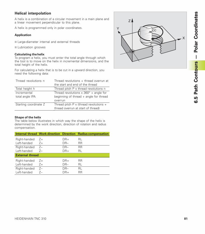
81HEIDENHAIN TNC 310
6.5
Path
Co
nto
urs
— P
ola
r C
oo
rdin
ate
sHelical interpolation
A helix is a combination of a circular movement in a main plane anda linear movement perpendicular to this plane.
A helix is programmed only in polar coordinates.
Application
■ Large-diameter internal and external threads
■ Lubrication grooves
Calculating the helixTo program a helix, you must enter the total angle through whichthe tool is to move on the helix in incremental dimensions, and thetotal height of the helix.
For calculating a helix that is to be cut in a upward direction, youneed the following data:
Y
X
Z
CC
Thread revolutions n
Total height hIncrementaltotal angle IPA
Starting coordinate Z
Thread revolutions + thread overrun atthe start and end of the threadThread pitch P x thread revolutions nThread revolutions x 360° + angle forbeginning of thread + angle for threadoverrunThread pitch P x (thread revolutions +thread overrun at start of thread)
Shape of the helixThe table below illustrates in which way the shape of the helix isdetermined by the work direction, direction of rotation and radiuscompensation.
Internal thread Work direction Direction Radius compensation
Right-handed Z+ DR+ RLLeft-handed Z+ DR– RRRight-handed Z– DR– RRLeft-handed Z– DR+ RLExternal thread
Right-handed Z+ DR+ RRLeft-handed Z+ DR– RLRight-handed Z– DR– RLLeft-handed Z– DR+ RR
6.5
Path
Co
nto
urs
— P
ola
r C
oo
rdin
ate
s
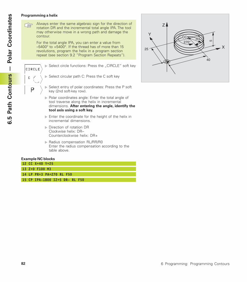
82 6 Programming: Programming Contours
6.5
Path
Co
nto
urs
— P
ola
r C
oo
rdin
ate
s Programming a helix
Always enter the same algebraic sign for the direction ofrotation DR and the incremental total angle IPA. The toolmay otherwise move in a wrong path and damage thecontour.
For the total angle IPA, you can enter a value from–5400° to +5400°. If the thread has of more than 15revolutions, program the helix in a program sectionrepeat (see section 9.2 ”Program Section Repeats”).
� Select circle functions: Press the „CIRCLE“ soft key
� Select circular path C: Press the C soft key
� Select entry of polar coordinates: Press the P softkey (2nd soft-key row).
� Polar coordinates angle: Enter the total angle oftool traverse along the helix in incrementaldimensions. After entering the angle, identify thetool axis using a soft key.
� Enter the coordinate for the height of the helix inincremental dimensions.
� Direction of rotation DRClockwise helix: DR–Counterclockwise helix: DR+
� Radius compensation RL/RR/R0Enter the radius compensation according to thetable above.
Example NC blocks
12 CC X+40 Y+2513 Z+0 F100 M314 LP PR+3 PA+270 RL F5015 CP IPA–1800 IZ+5 DR– RL F50
Y
X
Z
25
40
5270°R3CC
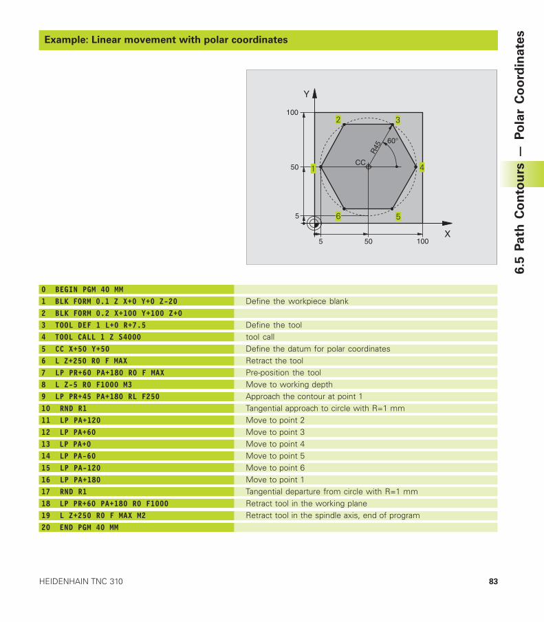
83HEIDENHAIN TNC 310
Example: Linear movement with polar coordinates
Define the workpiece blank
Define the tooltool callDefine the datum for polar coordinatesRetract the toolPre-position the toolMove to working depthApproach the contour at point 1Tangential approach to circle with R=1 mmMove to point 2Move to point 3Move to point 4Move to point 5Move to point 6Move to point 1Tangential departure from circle with R=1 mmRetract tool in the working planeRetract tool in the spindle axis, end of program
0 BEGIN PGM 40 MM1 BLK FORM 0.1 Z X+0 Y+0 Z-202 BLK FORM 0.2 X+100 Y+100 Z+03 TOOL DEF 1 L+0 R+7.54 TOOL CALL 1 Z S40005 CC X+50 Y+506 L Z+250 R0 F MAX7 LP PR+60 PA+180 R0 F MAX8 L Z-5 R0 F1000 M39 LP PR+45 PA+180 RL F25010 RND R111 LP PA+12012 LP PA+6013 LP PA+014 LP PA-6015 LP PA-12016 LP PA+18017 RND R118 LP PR+60 PA+180 R0 F100019 L Z+250 R0 F MAX M220 END PGM 40 MM
X
Y
50 100
50CC
5
100
R45
60°
5
6.5
Path
Co
nto
urs
— P
ola
r C
oo
rdin
ate
s
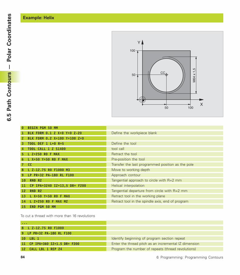
84 6 Programming: Programming Contours
Example: HelixExample: HelixExample: HelixExample: HelixExample: HelixExample: HelixExample: Helix
Define the workpiece blank
Define the tooltool callRetract the toolPre-position the toolTransfer the last programmed position as the poleMove to working depthApproach contourTangential approach to circle with R=2 mmHelical interpolationTangential departure from circle with R=2 mmRetract tool in the working planeRetract tool in the spindle axis, end of program
Identify beginning of program section repeatEnter the thread pitch as an incremental IZ dimensionProgram the number of repeats (thread revolutions)
0 BEGIN PGM 50 MM1 BLK FORM 0.1 Z X+0 Y+0 Z-202 BLK FORM 0.2 X+100 Y+100 Z+03 TOOL DEF 1 L+0 R+54 TOOL CALL 1 Z S14005 L Z+250 R0 F MAX6 L X+50 Y+50 R0 F MAX7 CC8 L Z-12.75 R0 F1000 M39 LP PR+32 PA-180 RL F10010 RND R211 CP IPA+3240 IZ+13,5 DR+ F20012 RND R213 L X+50 Y+50 R0 F MAX14 L Z+250 R0 F MAX M215 END PGM 50 MM
To cut a thread with more than 16 revolutions
...8 L Z-12.75 R0 F10009 LP PR+32 PA-180 RL F10010 LBL 111 CP IPA+360 IZ+1.5 DR+ F20012 CALL LBL 1 REP 24
X
Y
50
50CC
100
100
M64
x 1
,5
6.5
Path
Co
nto
urs
— P
ola
r C
oo
rdin
ate
s
Programming:
Miscellaneous functions
7
7 Programming: Miscellaneous functions86
7.1 Entering Miscellaneous FunctionsM and STOP
With the TNC's miscellaneous functions - also called M functions -you can affect:
■ Program run, e.g., a program interruption
■ Machine functions, such as switching spindle rotation and coolantsupply on and off
■ Contouring behavior of the tool
The machine tool builder may add some M functionsthat are not described in this User's Manual. Yourmachine manual provides more detailed information.
M functions are always entered at the end of a positioning block.The TNC then displays the following dialog question:
Miscellaneous function M ?
Only enter the number of the M function in the programmingdialog.
In the MANUAL OPERATION operating mode, the M functions areentered with the M soft key.
Please note that some F functions become effective at the start ofa positioning block, and others at the end.
M functions come into effect in the block in which they are called.Unless the M function is only effective blockwise, it is canceled in asubsequent block or at the end of the program. Some M functionsare effective only in the block in which they are called.
Entering an M function in a STOP blockIf you program a STOP block, the program run or test run isinterrupted at the block, for example for tool inspection. You canalso enter an M function in a STOP block:
� To program an interruption of program run,press the STOP key.
� Enter miscellaneous function M
Example NC block
87 STOP M6
7.1
En
teri
ng
Mis
ce
lla
ne
ou
s F
un
cti
on
s M
an
d S
TO
P
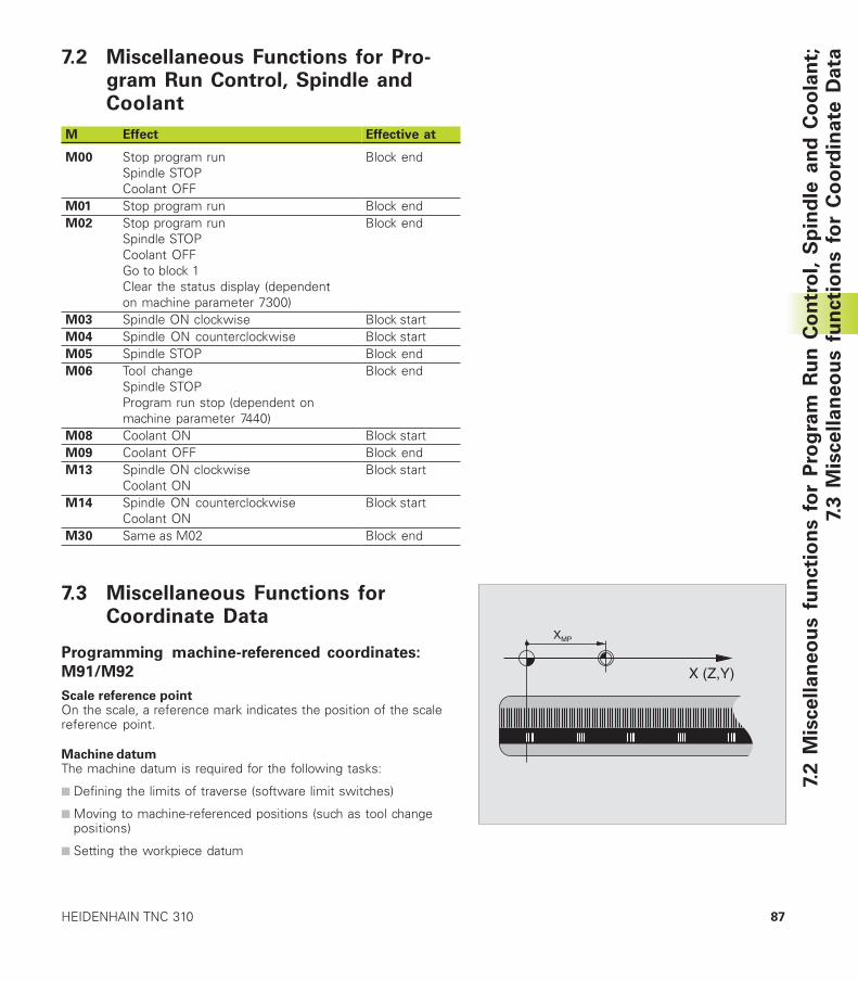
87HEIDENHAIN TNC 310
7.2 Miscellaneous Functions for Pro-gram Run Control, Spindle andCoolant
7.3 Miscellaneous Functions forCoordinate Data
Programming machine-referenced coordinates:
M91/M92
Scale reference pointOn the scale, a reference mark indicates the position of the scalereference point.
Machine datumThe machine datum is required for the following tasks:
■ Defining the limits of traverse (software limit switches)
■ Moving to machine-referenced positions (such as tool changepositions)
■ Setting the workpiece datum
X (Z,Y)
XMP
7.2 M
iscellan
eo
us f
un
cti
on
s f
or
Pro
gra
m R
un
Co
ntr
ol, S
pin
dle
an
d C
oo
lan
t;7.
3 M
isce
lla
ne
ou
s f
un
cti
on
s f
or
Co
ord
ina
te D
ata
M Effect
M00 Stop program runSpindle STOPCoolant OFF
M01 Stop program runM02 Stop program run
Spindle STOPCoolant OFFGo to block 1Clear the status display (dependenton machine parameter 7300)
M03 Spindle ON clockwiseM04 Spindle ON counterclockwiseM05 Spindle STOPM06 Tool change
Spindle STOPProgram run stop (dependent onmachine parameter 7440)
M08 Coolant ONM09 Coolant OFFM13 Spindle ON clockwise
Coolant ONM14 Spindle ON counterclockwise
Coolant ONM30 Same as M02
Effective at
Block end
Block endBlock end
Block startBlock startBlock endBlock end
Block startBlock endBlock start
Block start
Block end
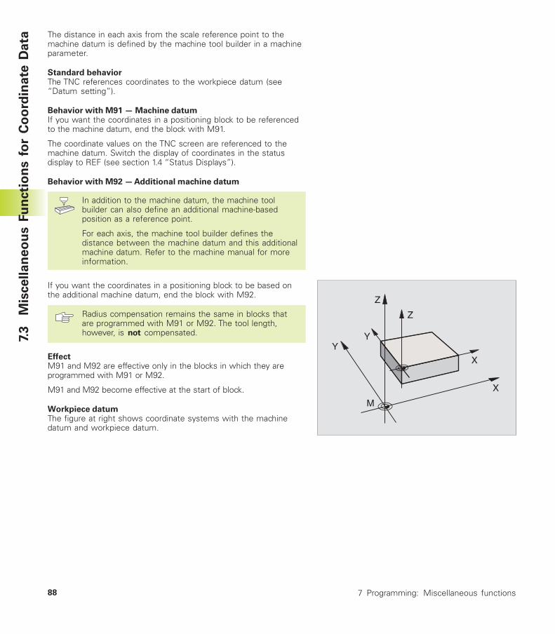
7 Programming: Miscellaneous functions88
The distance in each axis from the scale reference point to themachine datum is defined by the machine tool builder in a machineparameter.
Standard behaviorThe TNC references coordinates to the workpiece datum (see“Datum setting”).
Behavior with M91 — Machine datumIf you want the coordinates in a positioning block to be referencedto the machine datum, end the block with M91.
The coordinate values on the TNC screen are referenced to themachine datum. Switch the display of coordinates in the statusdisplay to REF (see section 1.4 “Status Displays”).
Behavior with M92 — Additional machine datum
In addition to the machine datum, the machine toolbuilder can also define an additional machine-basedposition as a reference point.
For each axis, the machine tool builder defines thedistance between the machine datum and this additionalmachine datum. Refer to the machine manual for moreinformation.
If you want the coordinates in a positioning block to be based onthe additional machine datum, end the block with M92.
Radius compensation remains the same in blocks thatare programmed with M91 or M92. The tool length,however, is not compensated.
EffectM91 and M92 are effective only in the blocks in which they areprogrammed with M91 or M92.
M91 and M92 become effective at the start of block.
Workpiece datumThe figure at right shows coordinate systems with the machinedatum and workpiece datum.
Z
X
Y
Z
Y
X
M
7.3
M
iscellan
eo
us F
un
cti
on
s f
or
Co
ord
inate
Data
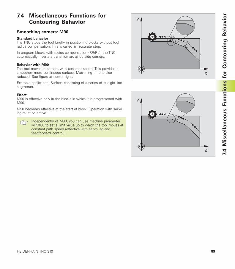
89HEIDENHAIN TNC 310
7.4 Miscellaneous Functions forContouring Behavior
Smoothing corners: M90
Standard behaviorThe TNC stops the tool briefly in positioning blocks without toolradius compensation. This is called an accurate stop.
In program blocks with radius compensation (RR/RL), the TNCautomatically inserts a transition arc at outside corners.
Behavior with M90The tool moves at corners with constant speed: This provides asmoother, more continuous surface. Machining time is alsoreduced. See figure at center right.
Example application: Surface consisting of a series of straight linesegments.
EffectM90 is effective only in the blocks in which it is programmed withM90.
M90 becomes effective at the start of block. Operation with servolag must be active.
Independently of M90, you can use machine parameterMP7460 to set a limit value up to which the tool moves atconstant path speed (effective with servo lag andfeedforward control).
X
Y
X
Y
7.4
Mis
ce
lla
ne
ou
s F
un
cti
on
s f
or
Co
nto
uri
ng
Be
hav
ior
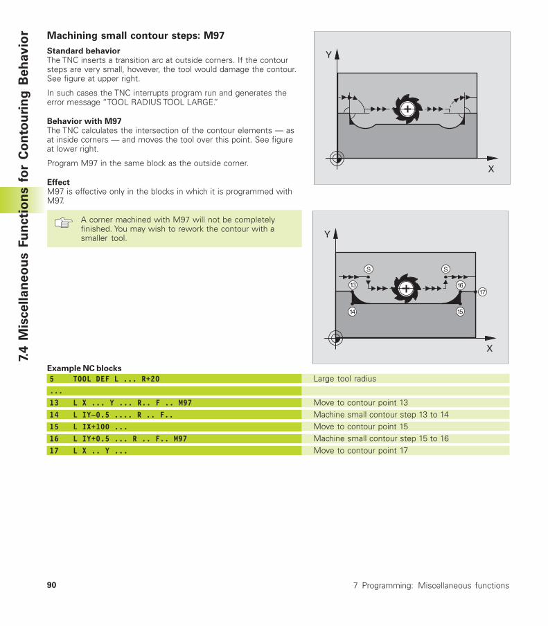
7 Programming: Miscellaneous functions90
Machining small contour steps: M97
Standard behaviorThe TNC inserts a transition arc at outside corners. If the contoursteps are very small, however, the tool would damage the contour.See figure at upper right.
In such cases the TNC interrupts program run and generates theerror message “TOOL RADIUS TOOL LARGE.”
Behavior with M97The TNC calculates the intersection of the contour elements — asat inside corners — and moves the tool over this point. See figureat lower right.
Program M97 in the same block as the outside corner.
EffectM97 is effective only in the blocks in which it is programmed withM97.
A corner machined with M97 will not be completelyfinished. You may wish to rework the contour with asmaller tool.
X
Y
X
Y
S
1617
1514
13
S
Large tool radius
Move to contour point 13Machine small contour step 13 to 14Move to contour point 15Machine small contour step 15 to 16Move to contour point 17
Example NC blocks
5 TOOL DEF L ... R+20...13 L X ... Y ... R.. F .. M9714 L IY–0.5 .... R .. F..15 L IX+100 ...16 L IY+0.5 ... R .. F.. M9717 L X .. Y ...
7.4
Mis
ce
lla
ne
ou
s F
un
cti
on
s f
or
Co
nto
uri
ng
Be
hav
ior
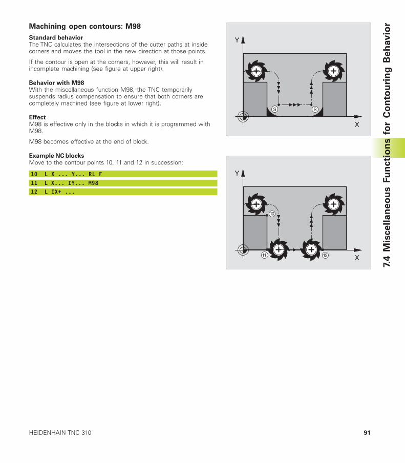
91HEIDENHAIN TNC 310
X
Y
S S
X
Y
11 12
10
7.4
Mis
ce
lla
ne
ou
s F
un
cti
on
s f
or
Co
nto
uri
ng
Be
hav
iorMachining open contours: M98
Standard behaviorThe TNC calculates the intersections of the cutter paths at insidecorners and moves the tool in the new direction at those points.
If the contour is open at the corners, however, this will result inincomplete machining (see figure at upper right).
Behavior with M98With the miscellaneous function M98, the TNC temporarilysuspends radius compensation to ensure that both corners arecompletely machined (see figure at lower right).
EffectM98 is effective only in the blocks in which it is programmed withM98.
M98 becomes effective at the end of block.
Example NC blocksMove to the contour points 10, 11 and 12 in succession:
10 L X ... Y... RL F11 L X... IY... M9812 L IX+ ...
7 Programming: Miscellaneous functions92
7.5
Mis
cellan
eo
us F
un
cti
on
fo
r R
ota
ry A
xes 7.5 Miscellaneous Function for Rotary
Axes
Reducing display of a rotary axis to a value less than
360°: M94
Standard behaviorThe TNC moves the tool from the current angular value to theprogrammed angular value.
Example:Current angular value: 538°Programmed angular value: 180°Actual path of traverse: –358°
Behavior with M94At the start of block, the TNC first reduces the current angular valueto a value less than 360° and then moves the tool to theprogrammed value. If several rotary axes are active, M94 willreduce the display of all rotary axes.
Example NC blocksTo reduce display of all active rotary axes:
L M94
To reduce display of all active rotary axes and then move the tool inthe C axis to the programmed value:
L C+180 FMAX M94
EffectM94 is effective only in the block in which M94 is programmed.
M94 becomes effective at the start of block.
Programming:
Cycles
8
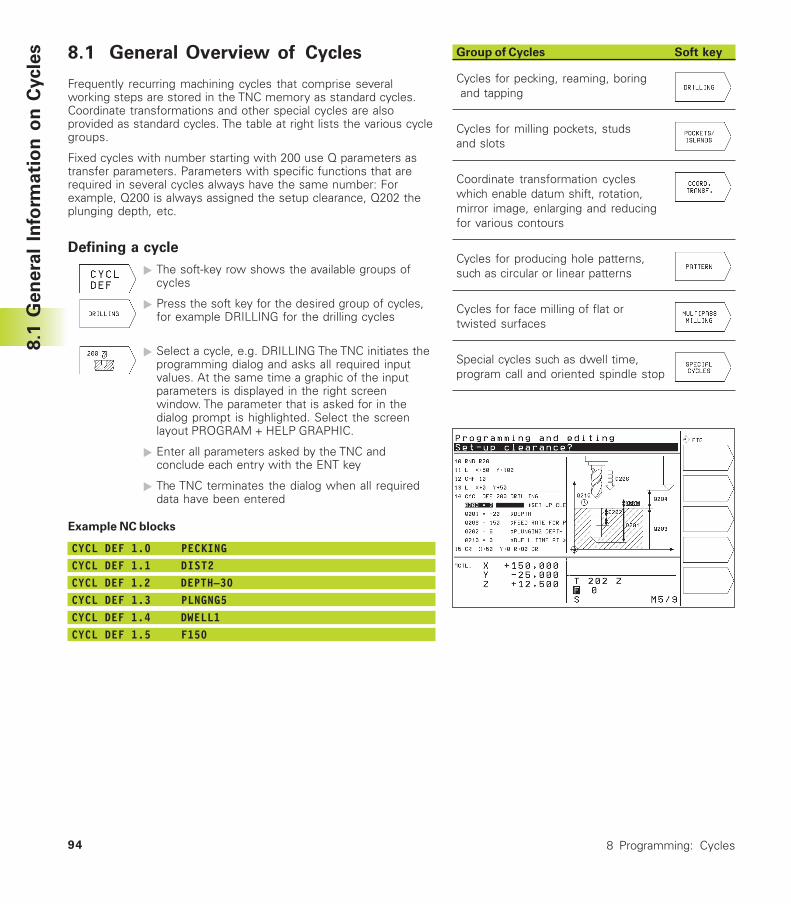
8 Programming: Cycles94
8.1 General Overview of Cycles
Frequently recurring machining cycles that comprise severalworking steps are stored in the TNC memory as standard cycles.Coordinate transformations and other special cycles are alsoprovided as standard cycles. The table at right lists the various cyclegroups.
Fixed cycles with number starting with 200 use Q parameters astransfer parameters. Parameters with specific functions that arerequired in several cycles always have the same number: Forexample, Q200 is always assigned the setup clearance, Q202 theplunging depth, etc.
Defining a cycle
� The soft-key row shows the available groups ofcycles
� Press the soft key for the desired group of cycles,for example DRILLING for the drilling cycles
� Select a cycle, e.g. DRILLING The TNC initiates theprogramming dialog and asks all required inputvalues. At the same time a graphic of the inputparameters is displayed in the right screenwindow. The parameter that is asked for in thedialog prompt is highlighted. Select the screenlayout PROGRAM + HELP GRAPHIC.
� Enter all parameters asked by the TNC andconclude each entry with the ENT key
� The TNC terminates the dialog when all requireddata have been entered
Example NC blocks
CYCL DEF 1.0 PECKINGCYCL DEF 1.1 DIST2CYCL DEF 1.2 DEPTH–30CYCL DEF 1.3 PLNGNG5CYCL DEF 1.4 DWELL1CYCL DEF 1.5 F150
Group of Cycles Soft key
Cycles for pecking, reaming, boring and tapping
Cycles for milling pockets, studsand slots
Coordinate transformation cycleswhich enable datum shift, rotation,mirror image, enlarging and reducingfor various contours
Cycles for producing hole patterns,such as circular or linear patterns
Cycles for face milling of flat ortwisted surfaces
Special cycles such as dwell time,program call and oriented spindle stop
8.1
Gen
era
l In
form
ati
on
on
Cycle
s
95HEIDENHAIN TNC 310
Calling the Cycle
Prerequisites
The following data must always be programmed before acycle call
■ BLK FORM for graphic display (needed only fortest graphics)
■ Tool call
■ Direction of spindle rotation (M functions M3/M4)
■ Cycle definition (CYCL DEF).
For some cycles, additional prerequisites must beobserved. They are described with the individual cycle.
The following cycles become effective automatically as soon asthey are defined in the part program. These cycles cannot and mustnot be called:
■ Cycles for circular and linear hole patterns
■ Coordinate transformation cycles
■ DWELL TIME cycle
All other cycles are called as described below.
If the TNC is to execute the cycle once after the last programmedblock, program the cycle call with the miscellaneous function M99or with CYCL CALL:
� Press the CYCL CALL soft key to program a cyclecall
� Enter a miscellaneous function, for example forcoolant supply.
If the TNC is to execute the cycle automatically after everypositioning block, program the cycle call with M89 (depending onmachine parameter 7440).
To cancel M89, enter
■ M99 or
■ CYCL CALL or
■ CYCL DEF
8.1
Gen
era
l In
form
ati
on
on
Cycle
s
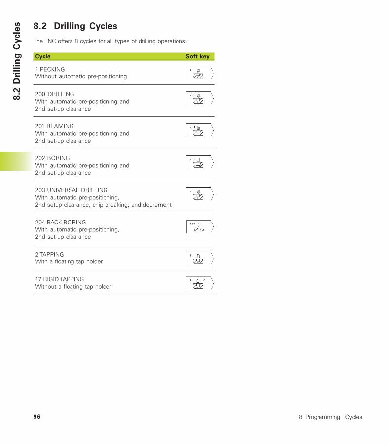
8 Programming: Cycles96
8.2 Drilling Cycles
The TNC offers 8 cycles for all types of drilling operations:
Cycle Soft key
1 PECKINGWithout automatic pre-positioning
200 DRILLINGWith automatic pre-positioning and2nd set-up clearance
201 REAMINGWith automatic pre-positioning and2nd set-up clearance
202 BORINGWith automatic pre-positioning and2nd set-up clearance
203 UNIVERSAL DRILLINGWith automatic pre-positioning,2nd setup clearance, chip breaking, and decrement
204 BACK BORINGWith automatic pre-positioning,2nd set-up clearance
2 TAPPINGWith a floating tap holder
17 RIGID TAPPINGWithout a floating tap holder
8.2
Dri
llin
g C
ycle
s
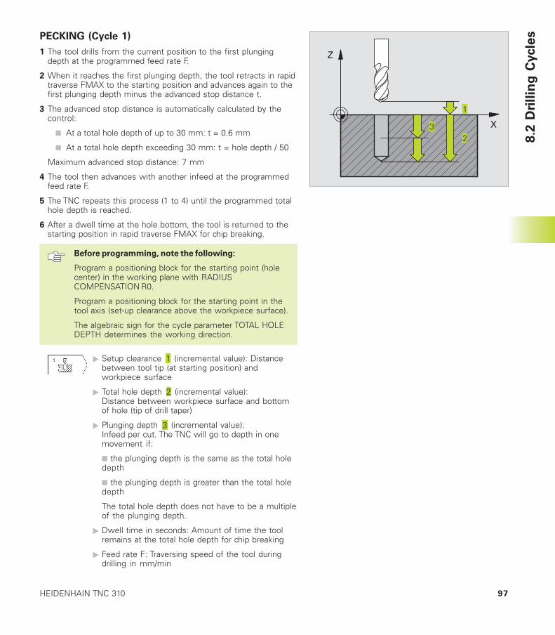
97HEIDENHAIN TNC 310
PECKING (Cycle 1)
1 The tool drills from the current position to the first plungingdepth at the programmed feed rate F.
2 When it reaches the first plunging depth, the tool retracts in rapidtraverse FMAX to the starting position and advances again to thefirst plunging depth minus the advanced stop distance t.
3 The advanced stop distance is automatically calculated by thecontrol:
■ At a total hole depth of up to 30 mm: t = 0.6 mm
■ At a total hole depth exceeding 30 mm: t = hole depth / 50
Maximum advanced stop distance: 7 mm
4 The tool then advances with another infeed at the programmedfeed rate F.
5 The TNC repeats this process (1 to 4) until the programmed totalhole depth is reached.
6 After a dwell time at the hole bottom, the tool is returned to thestarting position in rapid traverse FMAX for chip breaking.
Before programming, note the following:
Program a positioning block for the starting point (holecenter) in the working plane with RADIUSCOMPENSATION R0.
Program a positioning block for the starting point in thetool axis (set-up clearance above the workpiece surface).
The algebraic sign for the cycle parameter TOTAL HOLEDEPTH determines the working direction.
� Setup clearance (incremental value): Distancebetween tool tip (at starting position) andworkpiece surface
� Total hole depth (incremental value):Distance between workpiece surface and bottomof hole (tip of drill taper)
� Plunging depth (incremental value):Infeed per cut. The TNC will go to depth in onemovement if:
■ the plunging depth is the same as the total holedepth
■ the plunging depth is greater than the total holedepth
The total hole depth does not have to be a multipleof the plunging depth.
� Dwell time in seconds: Amount of time the toolremains at the total hole depth for chip breaking
� Feed rate F: Traversing speed of the tool duringdrilling in mm/min
8.2
Dri
llin
g C
ycle
s
X
Z
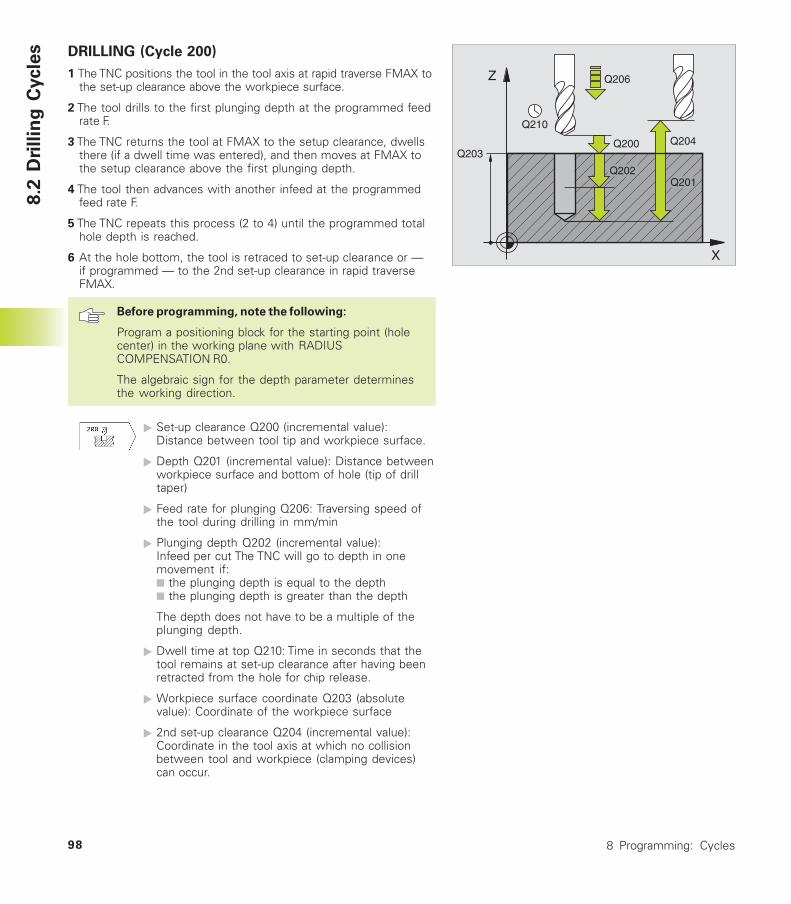
8 Programming: Cycles98
DRILLING (Cycle 200)
1 The TNC positions the tool in the tool axis at rapid traverse FMAX tothe set-up clearance above the workpiece surface.
2 The tool drills to the first plunging depth at the programmed feedrate F.
3 The TNC returns the tool at FMAX to the setup clearance, dwellsthere (if a dwell time was entered), and then moves at FMAX tothe setup clearance above the first plunging depth.
4 The tool then advances with another infeed at the programmedfeed rate F.
5 The TNC repeats this process (2 to 4) until the programmed totalhole depth is reached.
6 At the hole bottom, the tool is retraced to set-up clearance or —if programmed — to the 2nd set-up clearance in rapid traverseFMAX.
Before programming, note the following:
Program a positioning block for the starting point (holecenter) in the working plane with RADIUSCOMPENSATION R0.
The algebraic sign for the depth parameter determinesthe working direction.
� Set-up clearance Q200 (incremental value):Distance between tool tip and workpiece surface.
� Depth Q201 (incremental value): Distance betweenworkpiece surface and bottom of hole (tip of drilltaper)
� Feed rate for plunging Q206: Traversing speed ofthe tool during drilling in mm/min
� Plunging depth Q202 (incremental value):Infeed per cut The TNC will go to depth in onemovement if:■ the plunging depth is equal to the depth■ the plunging depth is greater than the depth
The depth does not have to be a multiple of theplunging depth.
� Dwell time at top Q210: Time in seconds that thetool remains at set-up clearance after having beenretracted from the hole for chip release.
� Workpiece surface coordinate Q203 (absolutevalue): Coordinate of the workpiece surface
� 2nd set-up clearance Q204 (incremental value):Coordinate in the tool axis at which no collisionbetween tool and workpiece (clamping devices)can occur.
X
Z
Q200
Q201
Q206
Q202
Q210
Q203Q204
8.2
Dri
llin
g C
ycle
s
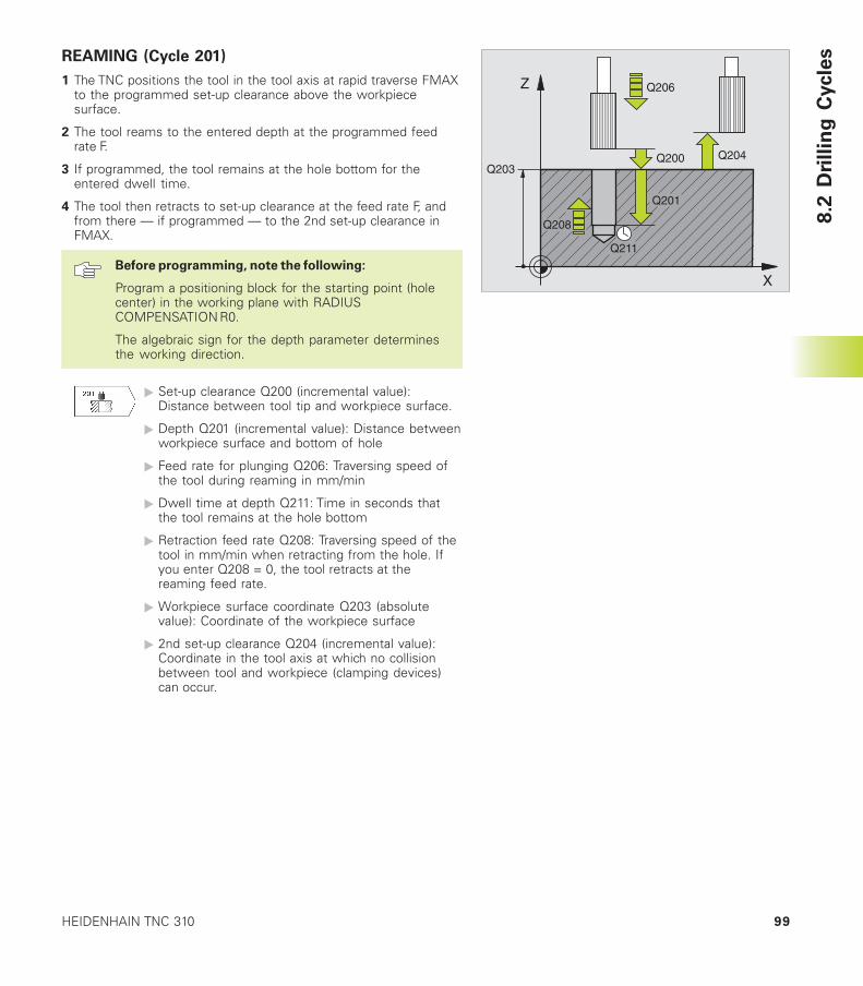
99HEIDENHAIN TNC 310
REAMING (Cycle 201)
1 The TNC positions the tool in the tool axis at rapid traverse FMAXto the programmed set-up clearance above the workpiecesurface.
2 The tool reams to the entered depth at the programmed feedrate F.
3 If programmed, the tool remains at the hole bottom for theentered dwell time.
4 The tool then retracts to set-up clearance at the feed rate F, andfrom there — if programmed — to the 2nd set-up clearance inFMAX.
Before programming, note the following:
Program a positioning block for the starting point (holecenter) in the working plane with RADIUSCOMPENSATION R0.
The algebraic sign for the depth parameter determinesthe working direction.
� Set-up clearance Q200 (incremental value):Distance between tool tip and workpiece surface.
� Depth Q201 (incremental value): Distance betweenworkpiece surface and bottom of hole
� Feed rate for plunging Q206: Traversing speed ofthe tool during reaming in mm/min
� Dwell time at depth Q211: Time in seconds thatthe tool remains at the hole bottom
� Retraction feed rate Q208: Traversing speed of thetool in mm/min when retracting from the hole. Ifyou enter Q208 = 0, the tool retracts at thereaming feed rate.
� Workpiece surface coordinate Q203 (absolutevalue): Coordinate of the workpiece surface
� 2nd set-up clearance Q204 (incremental value):Coordinate in the tool axis at which no collisionbetween tool and workpiece (clamping devices)can occur.
X
Z
Q200
Q201
Q206
Q211
Q203Q204
Q208 8.2
Dri
llin
g C
ycle
s
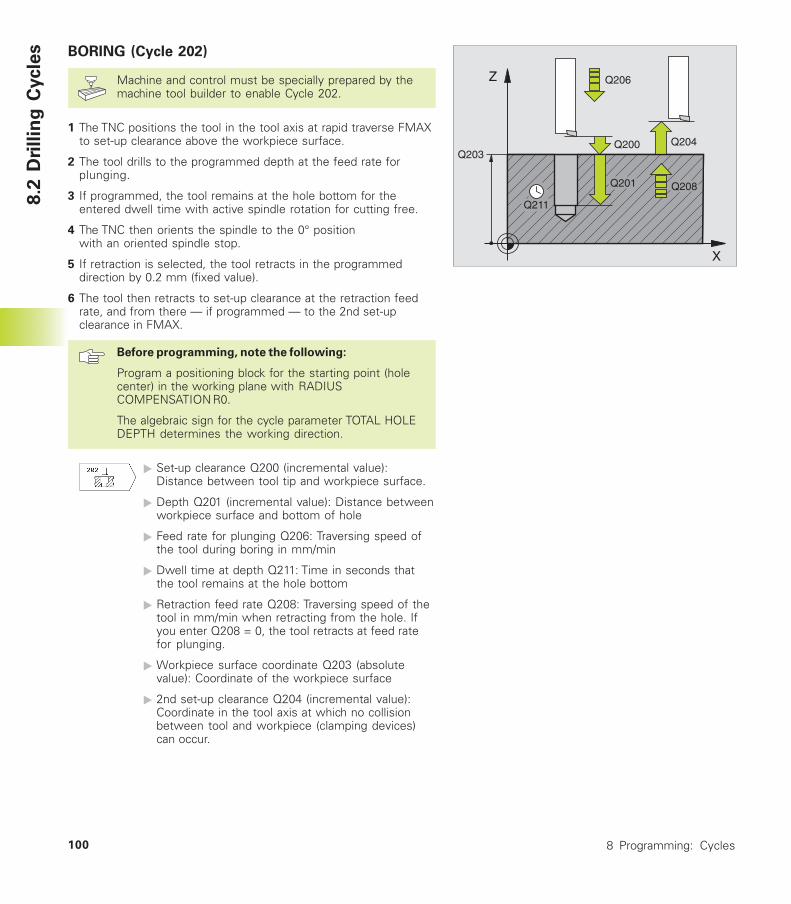
8 Programming: Cycles100
BORING (Cycle 202)
Machine and control must be specially prepared by themachine tool builder to enable Cycle 202.
1 The TNC positions the tool in the tool axis at rapid traverse FMAXto set-up clearance above the workpiece surface.
2 The tool drills to the programmed depth at the feed rate forplunging.
3 If programmed, the tool remains at the hole bottom for theentered dwell time with active spindle rotation for cutting free.
4 The TNC then orients the spindle to the 0° positionwith an oriented spindle stop.
5 If retraction is selected, the tool retracts in the programmeddirection by 0.2 mm (fixed value).
6 The tool then retracts to set-up clearance at the retraction feedrate, and from there — if programmed — to the 2nd set-upclearance in FMAX.
Before programming, note the following:
Program a positioning block for the starting point (holecenter) in the working plane with RADIUSCOMPENSATION R0.
The algebraic sign for the cycle parameter TOTAL HOLEDEPTH determines the working direction.
� Set-up clearance Q200 (incremental value):Distance between tool tip and workpiece surface.
� Depth Q201 (incremental value): Distance betweenworkpiece surface and bottom of hole
� Feed rate for plunging Q206: Traversing speed ofthe tool during boring in mm/min
� Dwell time at depth Q211: Time in seconds thatthe tool remains at the hole bottom
� Retraction feed rate Q208: Traversing speed of thetool in mm/min when retracting from the hole. Ifyou enter Q208 = 0, the tool retracts at feed ratefor plunging.
� Workpiece surface coordinate Q203 (absolutevalue): Coordinate of the workpiece surface
� 2nd set-up clearance Q204 (incremental value):Coordinate in the tool axis at which no collisionbetween tool and workpiece (clamping devices)can occur.
X
Z
Q200
Q201
Q206
Q211
Q203Q204
Q208
8.2
Dri
llin
g C
ycle
s
101HEIDENHAIN TNC 310
� Disengaging direction (0/1/2/3/4) Q214: Determinethe direction in which the TNC retracts the tool atthe hole bottom (after spindle orientation).
0: Do not retract tool
1: Retract tool in the negative main axis direction
2: Retract tool in the negative secondary axis direction
3: Retract tool in the positive main axis direction
4: Retract tool in the positive secondary axis direction
Danger of collision!
Check the position of the tool tip when you program aspindle orientation to 0° (for example, in the Positioningwith Manual Data Input mode of operation). Align thetool tip so that it is parallel to a coordinate axis. Select adisengaging direction in which the tool moves awayfrom the edge of the hole.
UNIVERSAL DRILLING (Cycle 203)
1 The TNC positions the tool in the tool axis at rapid traverse FMAXto the programmed set-up clearance above the workpiecesurface.
2 The tool drills to the first plunging depth at the programmed feedrate F.
3 If you have programmed chip breaking, the tool then retracts bythe setup clearance. If you are working without chip breaking, thetool retracts at the RETRACTION FEED RATE to setup clearance,remains there — if programmed — for the entered dwell time,and advances again in FMAX to the setup clearance above thefirst PLUNGING DEPTH.
4 The tool then advances with another infeed at the programmedfeed rate. If programmed, the plunging depth is decreased aftereach infeed by the decrement.
5 The TNC repeats this process (2 to 4) until the programmed totalhole depth is reached.
6 The tool remains at the hole bottom — if programmed — for theentered DWELL TIME to cut free, and then retracts to set-upclearance at the retraction feed rate. If you have entered a 2ndset-up clearance, the tool subsequently moves to that position inFMAX.
8.2
Dri
llin
g C
ycle
s
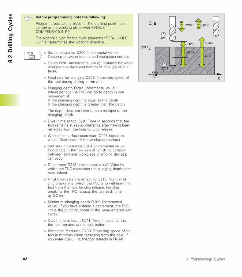
8 Programming: Cycles102
Before programming, note the following:
Program a positioning block for the starting point (holecenter) in the working plane with RADIUSCOMPENSATION R0.
The algebraic sign for the cycle parameter TOTAL HOLEDEPTH determines the working direction.
� Set-up clearance Q200 (incremental value):Distance between tool tip and workpiece surface.
� Depth Q201 (incremental value): Distance betweenworkpiece surface and bottom of hole (tip of drilltaper)
� Feed rate for plunging Q206: Traversing speed ofthe tool during drilling in mm/min
� Plunging depth Q202 (incremental value):Infeed per cut The TNC will go to depth in onemovement if:■ the plunging depth is equal to the depth■ the plunging depth is greater than the depth
The depth does not have to be a multiple of theplunging depth.
� Dwell time at top Q210: Time in seconds that thetool remains at set-up clearance after having beenretracted from the hole for chip release.
� Workpiece surface coordinate Q203 (absolutevalue): Coordinate of the workpiece surface
� 2nd set-up clearance Q204 (incremental value):Coordinate in the tool axis at which no collisionbetween tool and workpiece (clamping devices)can occur.
� Decrement Q212 (incremental value): Value bywhich the TNC decreases the plunging depth aftereach infeed.
� Nr of breaks before retracting Q213: Number ofchip breaks after which the TNC is to withdraw thetool from the hole for chip release. For chipbreaking, the TNC retracts the tool each timeby 0.2 mm.
� Minimum plunging depth Q205 (incrementalvalue): If you have entered a decrement, the TNClimits the plunging depth to the value entered withQ205.
� Dwell time at depth Q211: Time in seconds thatthe tool remains at the hole bottom
� Retraction feed rate Q208: Traversing speed of thetool in mm/min when retracting from the hole. Ifyou enter Q208 = 0, the tool retracts in FMAX.
X
Z
Q200
Q201
Q206
Q202
Q210
Q203Q204
Q211
Q208
8.2
Dri
llin
g C
ycle
s
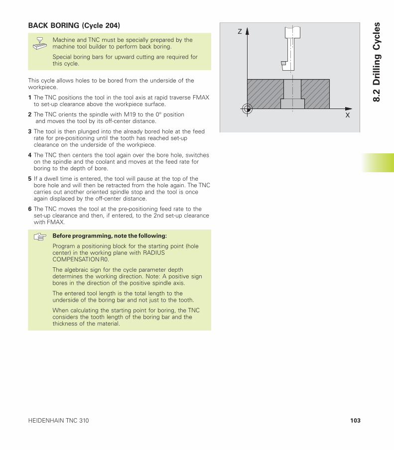
103HEIDENHAIN TNC 310
BACK BORING (Cycle 204)
Machine and TNC must be specially prepared by themachine tool builder to perform back boring.
Special boring bars for upward cutting are required forthis cycle.
This cycle allows holes to be bored from the underside of theworkpiece.
1 The TNC positions the tool in the tool axis at rapid traverse FMAXto set-up clearance above the workpiece surface.
2 The TNC orients the spindle with M19 to the 0° position and moves the tool by its off-center distance.
3 The tool is then plunged into the already bored hole at the feedrate for pre-positioning until the tooth has reached set-upclearance on the underside of the workpiece.
4 The TNC then centers the tool again over the bore hole, switcheson the spindle and the coolant and moves at the feed rate forboring to the depth of bore.
5 If a dwell time is entered, the tool will pause at the top of thebore hole and will then be retracted from the hole again. The TNCcarries out another oriented spindle stop and the tool is onceagain displaced by the off-center distance.
6 The TNC moves the tool at the pre-positioning feed rate to theset-up clearance and then, if entered, to the 2nd set-up clearancewith FMAX.
Before programming, note the following:
Program a positioning block for the starting point (holecenter) in the working plane with RADIUSCOMPENSATION R0.
The algebraic sign for the cycle parameter depthdetermines the working direction. Note: A positive signbores in the direction of the positive spindle axis.
The entered tool length is the total length to theunderside of the boring bar and not just to the tooth.
When calculating the starting point for boring, the TNCconsiders the tooth length of the boring bar and thethickness of the material.
X
Z
8.2
Dri
llin
g C
ycle
s
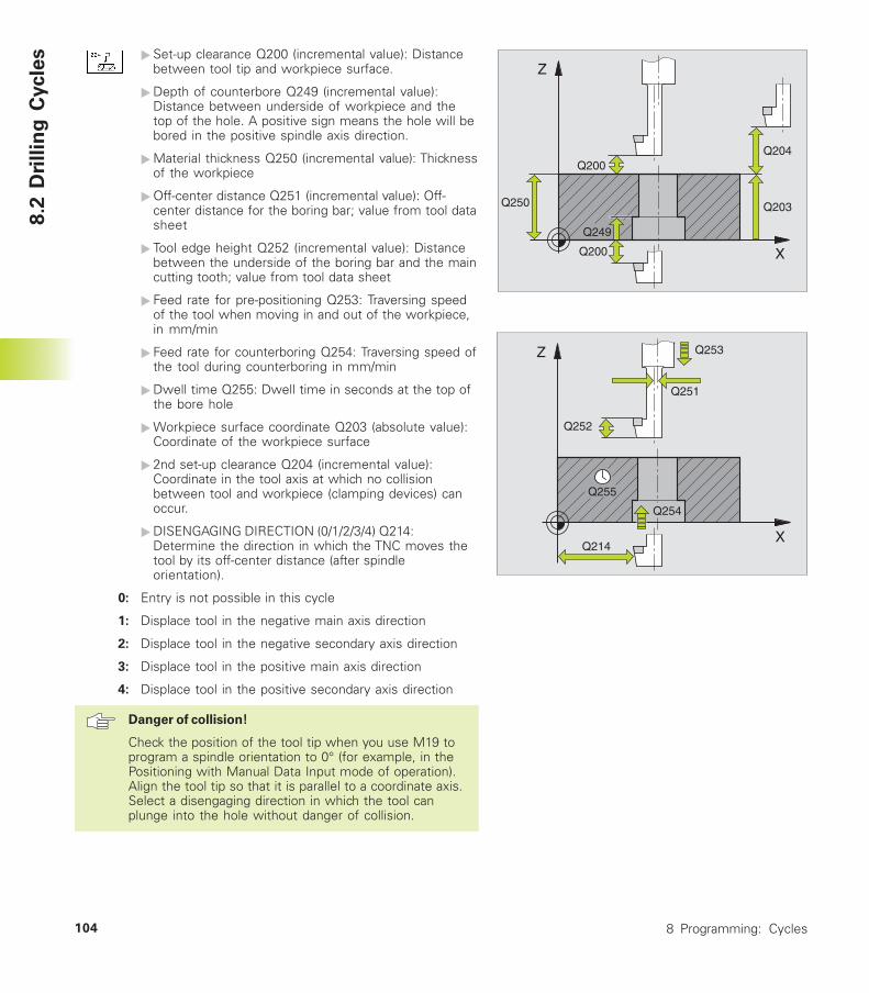
8 Programming: Cycles104
�Set-up clearance Q200 (incremental value): Distancebetween tool tip and workpiece surface.
�Depth of counterbore Q249 (incremental value):Distance between underside of workpiece and thetop of the hole. A positive sign means the hole will bebored in the positive spindle axis direction.
�Material thickness Q250 (incremental value): Thicknessof the workpiece
�Off-center distance Q251 (incremental value): Off-center distance for the boring bar; value from tool datasheet
� Tool edge height Q252 (incremental value): Distancebetween the underside of the boring bar and the maincutting tooth; value from tool data sheet
� Feed rate for pre-positioning Q253: Traversing speedof the tool when moving in and out of the workpiece,in mm/min
� Feed rate for counterboring Q254: Traversing speed ofthe tool during counterboring in mm/min
�Dwell time Q255: Dwell time in seconds at the top ofthe bore hole
�Workpiece surface coordinate Q203 (absolute value):Coordinate of the workpiece surface
� 2nd set-up clearance Q204 (incremental value):Coordinate in the tool axis at which no collisionbetween tool and workpiece (clamping devices) canoccur.
�DISENGAGING DIRECTION (0/1/2/3/4) Q214:Determine the direction in which the TNC moves thetool by its off-center distance (after spindleorientation).
0: Entry is not possible in this cycle
1: Displace tool in the negative main axis direction
2: Displace tool in the negative secondary axis direction
3: Displace tool in the positive main axis direction
4: Displace tool in the positive secondary axis direction
Danger of collision!
Check the position of the tool tip when you use M19 toprogram a spindle orientation to 0° (for example, in thePositioning with Manual Data Input mode of operation).Align the tool tip so that it is parallel to a coordinate axis.Select a disengaging direction in which the tool canplunge into the hole without danger of collision.
X
Z
Q250 Q203
Q204
Q249
Q200
Q200
X
Z
Q255
Q254
Q214
Q252
Q253
Q251
8.2
Dri
llin
g C
ycle
s
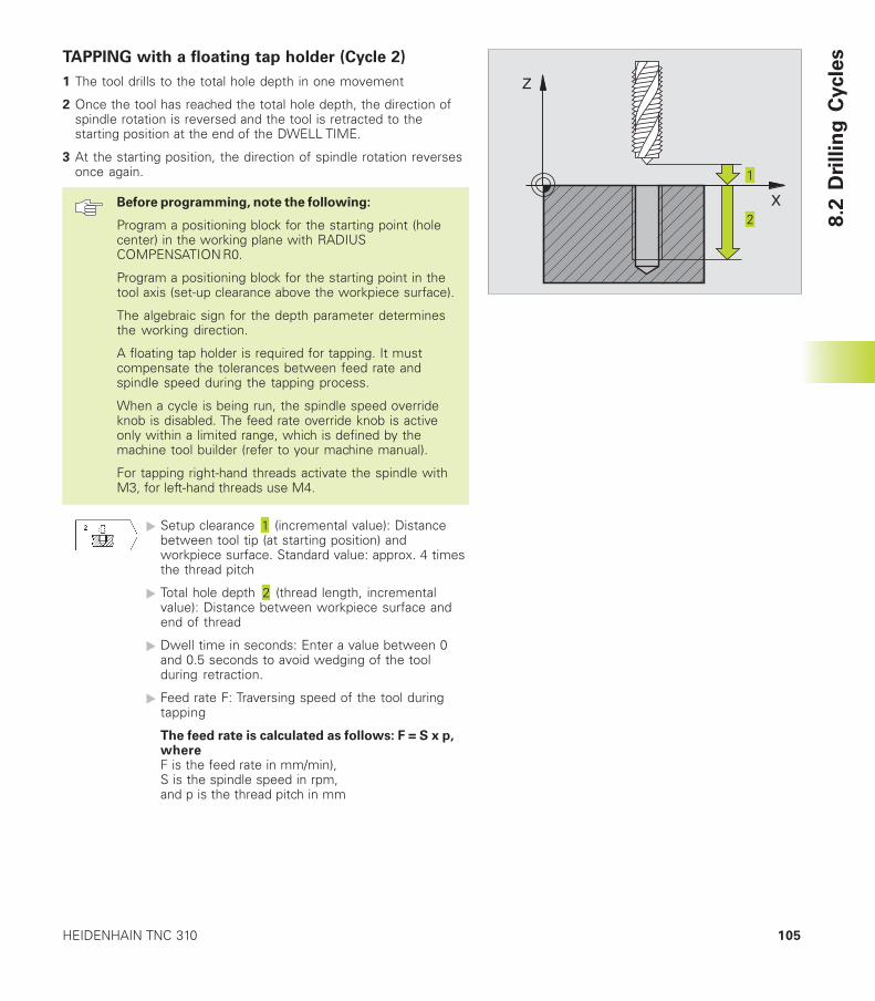
105HEIDENHAIN TNC 310
TAPPING with a floating tap holder (Cycle 2)
1 The tool drills to the total hole depth in one movement
2 Once the tool has reached the total hole depth, the direction ofspindle rotation is reversed and the tool is retracted to thestarting position at the end of the DWELL TIME.
3 At the starting position, the direction of spindle rotation reversesonce again.
Before programming, note the following:
Program a positioning block for the starting point (holecenter) in the working plane with RADIUSCOMPENSATION R0.
Program a positioning block for the starting point in thetool axis (set-up clearance above the workpiece surface).
The algebraic sign for the depth parameter determinesthe working direction.
A floating tap holder is required for tapping. It mustcompensate the tolerances between feed rate andspindle speed during the tapping process.
When a cycle is being run, the spindle speed overrideknob is disabled. The feed rate override knob is activeonly within a limited range, which is defined by themachine tool builder (refer to your machine manual).
For tapping right-hand threads activate the spindle withM3, for left-hand threads use M4.
� Setup clearance (incremental value): Distancebetween tool tip (at starting position) andworkpiece surface. Standard value: approx. 4 timesthe thread pitch
� Total hole depth (thread length, incrementalvalue): Distance between workpiece surface andend of thread
� Dwell time in seconds: Enter a value between 0and 0.5 seconds to avoid wedging of the toolduring retraction.
� Feed rate F: Traversing speed of the tool duringtapping
The feed rate is calculated as follows: F = S x p,whereF is the feed rate in mm/min),S is the spindle speed in rpm,and p is the thread pitch in mm
8.2
Dri
llin
g C
ycle
s
X
Z
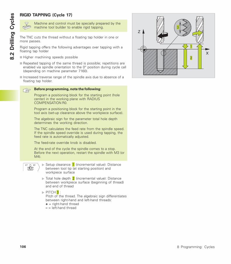
8 Programming: Cycles106
RIGID TAPPING (Cycle 17)
Machine and control must be specially prepared by themachine tool builder to enable rigid tapping.
The TNC cuts the thread without a floating tap holder in one ormore passes.
Rigid tapping offers the following advantages over tapping with afloating tap holder
■ Higher machining speeds possible
■ Repeated tapping of the same thread is possible; repetitions areenabled via spindle orientation to the 0° position during cycle call(depending on machine parameter 7160).
■ Increased traverse range of the spindle axis due to absence of afloating tap holder.
Before programming, note the following:
Program a positioning block for the starting point (holecenter) in the working plane with RADIUSCOMPENSATION R0.
Program a positioning block for the starting point in thetool axis (set-up clearance above the workpiece surface).
The algebraic sign for the parameter total hole depthdetermines the working direction.
The TNC calculates the feed rate from the spindle speed.If the spindle speed override is used during tapping, thefeed rate is automatically adjusted.
The feed-rate override knob is disabled.
At the end of the cycle the spindle comes to a stop.Before the next operation, restart the spindle with M3 (orM4).
� Setup clearance (incremental value): Distancebetween tool tip (at starting position) andworkpiece surface
� Total hole depth (incremental value): Distancebetween workpiece surface (beginning of thread)and end of thread
� PITCH :Pitch of the thread. The algebraic sign differentiatesbetween right-hand and left-hand threads:+ = right-hand thread– = left-hand thread
8.2
Dri
llin
g C
ycle
s
X
Z
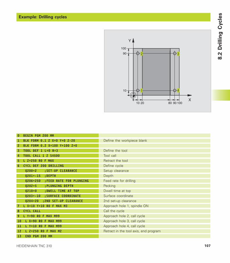
107HEIDENHAIN TNC 310
Example: Drilling cycles
8.2
Dri
llin
g C
ycle
s
X
Y
20
10
100
100
10
90
9080
Define the workpiece blank
Define the toolTool callRetract the toolDefine cycleSetup clearanceDepthFeed rate for drillingPeckingDwell time at topSurface coordinate2nd set-up clearanceApproach hole 1, spindle ONCall the cycleApproach hole 2, call cycleApproach hole 3, call cycleApproach hole 4, call cycleRetract in the tool axis, end program
0 BEGIN PGM 200 MM1 BLK FORM 0.1 Z X+0 Y+0 Z-202 BLK FORM 0.2 X+100 Y+100 Z+03 TOOL DEF 1 L+0 R+34 TOOL CALL 1 Z S45005 L Z+250 R0 F MAX6 CYCL DEF 200 DRILLING Q200=2 ;SET-UP CLEARANCE Q201=-15 ;DEPTH Q206=250 ;FEED RATE FOR PLUNGING Q202=5 ;PLUNGING DEPTH Q210=0 ;DWELL TIME AT TOP Q203=-10 ;SURFACE COORDINATE Q204=20 ;2ND SET-UP CLEARANCE7 L X+10 Y+10 R0 F MAX M38 CYCL CALL9 L Y+90 R0 F MAX M9910 L X+90 R0 F MAX M9911 L Y+10 R0 F MAX M9912 L Z+250 R0 F MAX M213 END PGM 200 MM

8 Programming: Cycles108
Example: Drilling cycles
Program sequence■ Plate has already been pilot drilled for
M12, depth of the plate: 20 mm
■ Program tapping cycle
■ For safety reasons, pre-positioning should bedone first of all in the main plane and then in thespindle axis8
.2 D
rillin
g C
ycle
s
X
Y
20
20
100
100
70
70
M12
M12
Define the workpiece blank
Define the toolTool callRetract the toolCycle definition for tapping
Approach hole 1 in the machining planePre-position in the tool axisApproach hole 2 in the machining planeRetract in the tool axis, end program
0 BEGIN PGM 2 MM1 BLK FORM 0.1 Z X+0 Y+0 Z-202 BLK FORM 0.2 X+100 Y+100 Z+03 TOOL DEF 1 L+0 R+4.54 TOOL CALL 1 Z S1005 L Z+250 R0 FMAX6 CYCL DEF 2 .0 TAPPING7 CYCL DEF 2 .1 SET UP 28 CYCL DEF 2 .2 DEPTH -259 CYCL DEF 2 .3 DWELL 010 CYCL DEF 2 .4 F17511 L X+20 Y+20 R0 FMAX M312 L Z+2 R0 FMAX M9913 L X+70 Y+70 R0 FMAX M9914 L Z+250 R0 FMAX M215 END PGM 2 MM
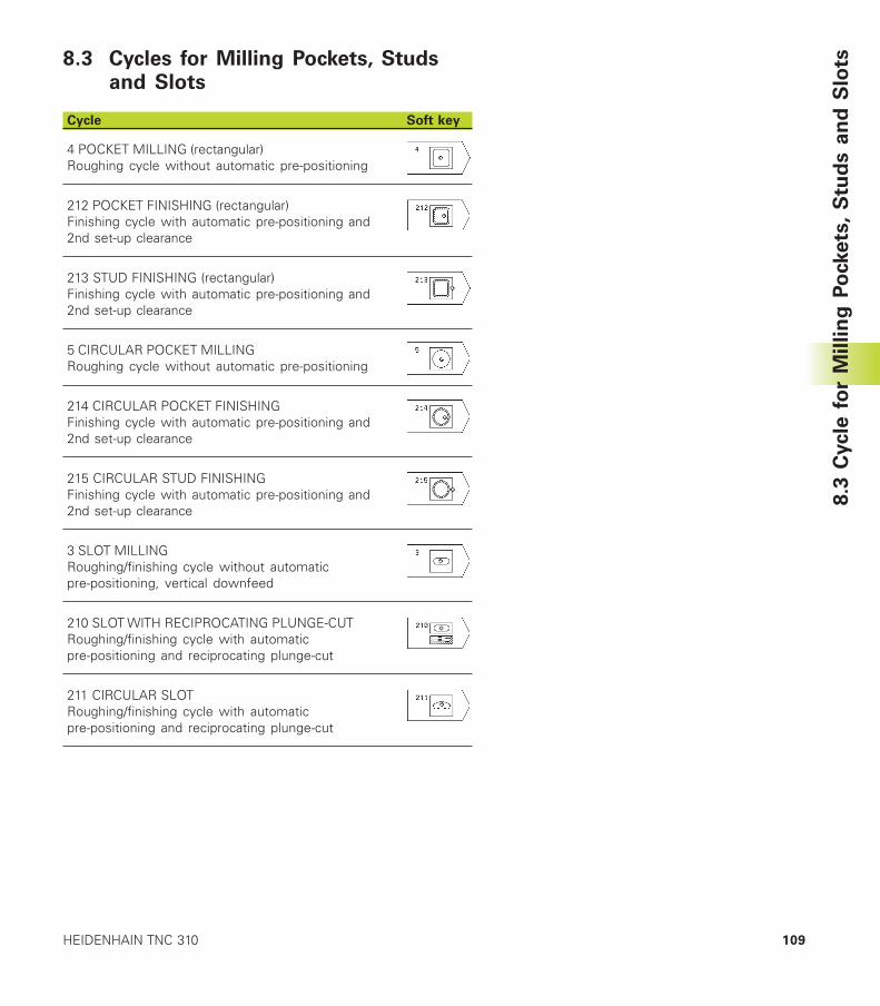
109HEIDENHAIN TNC 310
8.3 Cycles for Milling Pockets, Studsand Slots
Cycle Soft key
4 POCKET MILLING (rectangular)Roughing cycle without automatic pre-positioning
212 POCKET FINISHING (rectangular)Finishing cycle with automatic pre-positioning and2nd set-up clearance
213 STUD FINISHING (rectangular)Finishing cycle with automatic pre-positioning and2nd set-up clearance
5 CIRCULAR POCKET MILLINGRoughing cycle without automatic pre-positioning
214 CIRCULAR POCKET FINISHINGFinishing cycle with automatic pre-positioning and2nd set-up clearance
215 CIRCULAR STUD FINISHINGFinishing cycle with automatic pre-positioning and2nd set-up clearance
3 SLOT MILLINGRoughing/finishing cycle without automaticpre-positioning, vertical downfeed
210 SLOT WITH RECIPROCATING PLUNGE-CUTRoughing/finishing cycle with automaticpre-positioning and reciprocating plunge-cut
211 CIRCULAR SLOTRoughing/finishing cycle with automaticpre-positioning and reciprocating plunge-cut
8.3
Cycle
fo
r M
illin
g P
ockets
, S
tud
s a
nd
Slo
ts
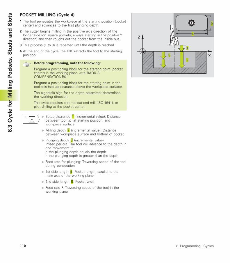
8 Programming: Cycles110
POCKET MILLING (Cycle 4)
1 The tool penetrates the workpiece at the starting position (pocketcenter) and advances to the first plunging depth.
2 The cutter begins milling in the positive axis direction of thelonger side (on square pockets, always starting in the positive Ydirection) and then roughs out the pocket from the inside out.
3 This process (1 to 3) is repeated until the depth is reached.
4 At the end of the cycle, the TNC retracts the tool to the startingposition.
Before programming, note the following:
Program a positioning block for the starting point (pocketcenter) in the working plane with RADIUSCOMPENSATION R0.
Program a positioning block for the starting point in thetool axis (set-up clearance above the workpiece surface).
The algebraic sign for the depth parameter determinesthe working direction.
This cycle requires a center-cut end mill (ISO 1641), orpilot drilling at the pocket center.
� Setup clearance (incremental value): Distancebetween tool tip (at starting position) andworkpiece surface
� Milling depth (incremental value): Distancebetween workpiece surface and bottom of pocket
� Plunging depth (incremental value):Infeed per cut. The tool will advance to the depth inone movement if:n the plunging depth equals the depthn the plunging depth is greater than the depth
� Feed rate for plunging: Traversing speed of the toolduring penetration
� 1st side length : Pocket length, parallel to themain axis of the working plane
� 2nd side length : Pocket width
� Feed rate F: Traversing speed of the tool in theworking plane
8.3
Cycle
fo
r M
illin
g P
ockets
, S
tud
s a
nd
Slo
ts
X
Z
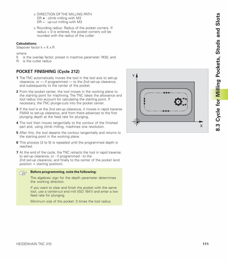
111HEIDENHAIN TNC 310
�DIRECTION OF THE MILLING PATHDR + : climb milling with M3DR – : up-cut milling with M3
�Rounding radius: Radius of the pocket corners. Ifradius = 0 is entered, the pocket corners will berounded with the radius of the cutter.
Calculations:Stepover factor k = K x R
whereK is the overlap factor, preset in machine parameter 7430, andR: is the cutter radius
POCKET FINISHING (Cycle 212)
1 The TNC automatically moves the tool in the tool axis to set-upclearance, or — if programmed — to the 2nd set-up clearance,and subsequently to the center of the pocket.
2 From the pocket center, the tool moves in the working plane tothe starting point for machining. The TNC takes the allowance andtool radius into account for calculating the starting point. Ifnecessary, the TNC plunge-cuts into the pocket center.
3 If the tool is at the 2nd set-up clearance, it moves in rapid traverseFMAX to set-up clearance, and from there advances to the firstplunging depth at the feed rate for plunging.
4 The tool then moves tangentially to the contour of the finishedpart and, using climb milling, machines one revolution.
5 After this, the tool departs the contour tangentially and returns tothe starting point in the working plane.
6 This process (3 to 5) is repeated until the programmed depth isreached.
7 At the end of the cycle, the TNC retracts the tool in rapid traverseto set-up clearance, or - if programmed - to the2nd set-up clearance, and finally to the center of the pocket (endposition = starting position).
Before programming, note the following:
The algebraic sign for the depth parameter determinesthe working direction.
If you want to clear and finish the pocket with the sametool, use a center-cut end mill (ISO 1641) and enter a lowfeed rate for plunging.
Minimum size of the pocket: 3 times the tool radius.
8.3
Cycle
fo
r M
illin
g P
ockets
, S
tud
s a
nd
Slo
ts
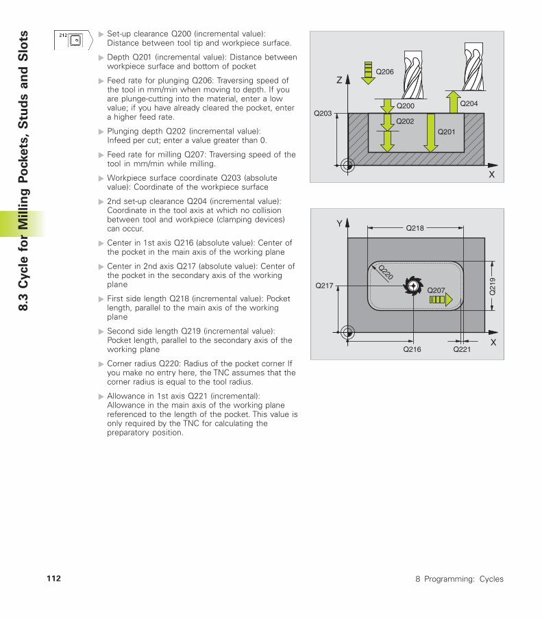
8 Programming: Cycles112
� Set-up clearance Q200 (incremental value):Distance between tool tip and workpiece surface.
� Depth Q201 (incremental value): Distance betweenworkpiece surface and bottom of pocket
� Feed rate for plunging Q206: Traversing speed ofthe tool in mm/min when moving to depth. If youare plunge-cutting into the material, enter a lowvalue; if you have already cleared the pocket, entera higher feed rate.
� Plunging depth Q202 (incremental value):Infeed per cut; enter a value greater than 0.
� Feed rate for milling Q207: Traversing speed of thetool in mm/min while milling.
� Workpiece surface coordinate Q203 (absolutevalue): Coordinate of the workpiece surface
� 2nd set-up clearance Q204 (incremental value):Coordinate in the tool axis at which no collisionbetween tool and workpiece (clamping devices)can occur.
� Center in 1st axis Q216 (absolute value): Center ofthe pocket in the main axis of the working plane
� Center in 2nd axis Q217 (absolute value): Center ofthe pocket in the secondary axis of the workingplane
� First side length Q218 (incremental value): Pocketlength, parallel to the main axis of the workingplane
� Second side length Q219 (incremental value):Pocket length, parallel to the secondary axis of theworking plane
� Corner radius Q220: Radius of the pocket corner Ifyou make no entry here, the TNC assumes that thecorner radius is equal to the tool radius.
� Allowance in 1st axis Q221 (incremental):Allowance in the main axis of the working planereferenced to the length of the pocket. This value isonly required by the TNC for calculating thepreparatory position.
X
Z
Q200
Q201
Q206
Q202Q203
Q204
8.3
Cycle
fo
r M
illin
g P
ockets
, S
tud
s a
nd
Slo
ts
X
Y
Q21
9
Q218
Q217
Q216
Q207
Q221
Q220
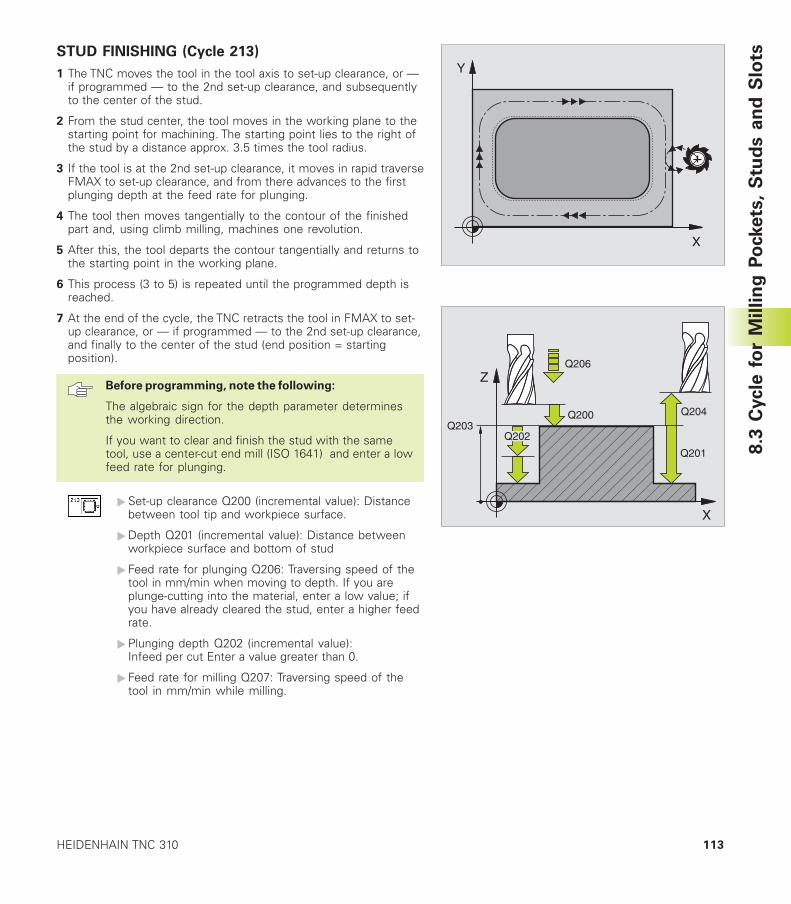
113HEIDENHAIN TNC 310
STUD FINISHING (Cycle 213)
1 The TNC moves the tool in the tool axis to set-up clearance, or —if programmed — to the 2nd set-up clearance, and subsequentlyto the center of the stud.
2 From the stud center, the tool moves in the working plane to thestarting point for machining. The starting point lies to the right ofthe stud by a distance approx. 3.5 times the tool radius.
3 If the tool is at the 2nd set-up clearance, it moves in rapid traverseFMAX to set-up clearance, and from there advances to the firstplunging depth at the feed rate for plunging.
4 The tool then moves tangentially to the contour of the finishedpart and, using climb milling, machines one revolution.
5 After this, the tool departs the contour tangentially and returns tothe starting point in the working plane.
6 This process (3 to 5) is repeated until the programmed depth isreached.
7 At the end of the cycle, the TNC retracts the tool in FMAX to set-up clearance, or — if programmed — to the 2nd set-up clearance,and finally to the center of the stud (end position = startingposition).
Before programming, note the following:
The algebraic sign for the depth parameter determinesthe working direction.
If you want to clear and finish the stud with the sametool, use a center-cut end mill (ISO 1641) and enter a lowfeed rate for plunging.
�Set-up clearance Q200 (incremental value): Distancebetween tool tip and workpiece surface.
�Depth Q201 (incremental value): Distance betweenworkpiece surface and bottom of stud
� Feed rate for plunging Q206: Traversing speed of thetool in mm/min when moving to depth. If you areplunge-cutting into the material, enter a low value; ifyou have already cleared the stud, enter a higher feedrate.
�Plunging depth Q202 (incremental value):Infeed per cut Enter a value greater than 0.
� Feed rate for milling Q207: Traversing speed of thetool in mm/min while milling.
X
Y
X
Z
Q200
Q201
Q206
Q203Q204
Q202
8.3
Cycle
fo
r M
illin
g P
ockets
, S
tud
s a
nd
Slo
ts
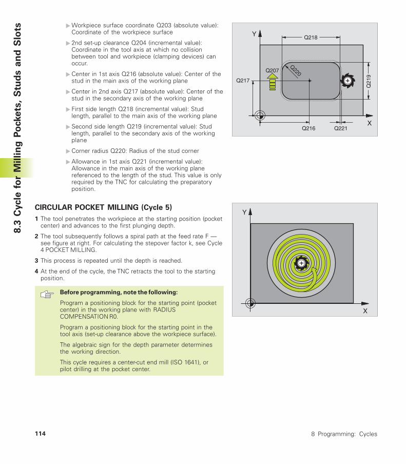
8 Programming: Cycles114
�Workpiece surface coordinate Q203 (absolute value):Coordinate of the workpiece surface
� 2nd set-up clearance Q204 (incremental value):Coordinate in the tool axis at which no collisionbetween tool and workpiece (clamping devices) canoccur.
�Center in 1st axis Q216 (absolute value): Center of thestud in the main axis of the working plane
�Center in 2nd axis Q217 (absolute value): Center of thestud in the secondary axis of the working plane
� First side length Q218 (incremental value): Studlength, parallel to the main axis of the working plane
�Second side length Q219 (incremental value): Studlength, parallel to the secondary axis of the workingplane
�Corner radius Q220: Radius of the stud corner
�Allowance in 1st axis Q221 (incremental value):Allowance in the main axis of the working planereferenced to the length of the stud. This value is onlyrequired by the TNC for calculating the preparatoryposition.
CIRCULAR POCKET MILLING (Cycle 5)
1 The tool penetrates the workpiece at the starting position (pocketcenter) and advances to the first plunging depth.
2 The tool subsequently follows a spiral path at the feed rate F —see figure at right. For calculating the stepover factor k, see Cycle4 POCKET MILLING.
3 This process is repeated until the depth is reached.
4 At the end of the cycle, the TNC retracts the tool to the startingposition.
Before programming, note the following:
Program a positioning block for the starting point (pocketcenter) in the working plane with RADIUSCOMPENSATION R0.
Program a positioning block for the starting point in thetool axis (set-up clearance above the workpiece surface).
The algebraic sign for the depth parameter determinesthe working direction.
This cycle requires a center-cut end mill (ISO 1641), orpilot drilling at the pocket center.
X
Y
Q21
9
Q218
Q217
Q216
Q207
Q221
Q220
8.3
Cycle
fo
r M
illin
g P
ockets
, S
tud
s a
nd
Slo
ts
X
Y
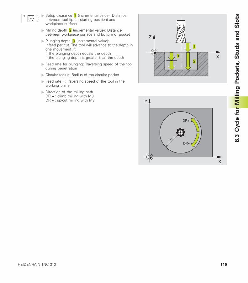
115HEIDENHAIN TNC 310
� Setup clearance (incremental value): Distancebetween tool tip (at starting position) andworkpiece surface
� Milling depth (incremental value): Distancebetween workpiece surface and bottom of pocket
� Plunging depth (incremental value):Infeed per cut. The tool will advance to the depth inone movement if:n the plunging depth equals the depthn the plunging depth is greater than the depth
� Feed rate for plunging: Traversing speed of the toolduring penetration
� Circular radius: Radius of the circular pocket
� Feed rate F: Traversing speed of the tool in theworking plane
� Direction of the milling pathDR + : climb milling with M3DR – : up-cut milling with M3
8.3
Cycle
fo
r M
illin
g P
ockets
, S
tud
s a
nd
Slo
ts
X
Y
DR+
R
X
Z
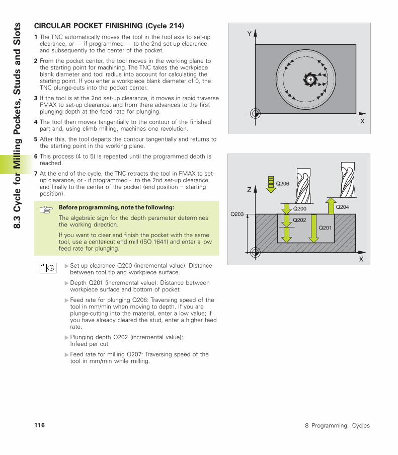
8 Programming: Cycles116
CIRCULAR POCKET FINISHING (Cycle 214)
1 The TNC automatically moves the tool in the tool axis to set-upclearance, or — if programmed — to the 2nd set-up clearance,and subsequently to the center of the pocket.
2 From the pocket center, the tool moves in the working plane tothe starting point for machining. The TNC takes the workpieceblank diameter and tool radius into account for calculating thestarting point. If you enter a workpiece blank diameter of 0, theTNC plunge-cuts into the pocket center.
3 If the tool is at the 2nd set-up clearance, it moves in rapid traverseFMAX to set-up clearance, and from there advances to the firstplunging depth at the feed rate for plunging.
4 The tool then moves tangentially to the contour of the finishedpart and, using climb milling, machines one revolution.
5 After this, the tool departs the contour tangentially and returns tothe starting point in the working plane.
6 This process (4 to 5) is repeated until the programmed depth isreached.
7 At the end of the cycle, the TNC retracts the tool in FMAX to set-up clearance, or - if programmed - to the 2nd set-up clearance,and finally to the center of the pocket (end position = startingposition).
Before programming, note the following:
The algebraic sign for the depth parameter determinesthe working direction.
If you want to clear and finish the pocket with the sametool, use a center-cut end mill (ISO 1641) and enter a lowfeed rate for plunging.
�Set-up clearance Q200 (incremental value): Distancebetween tool tip and workpiece surface.
�Depth Q201 (incremental value): Distance betweenworkpiece surface and bottom of pocket
� Feed rate for plunging Q206: Traversing speed of thetool in mm/min when moving to depth. If you areplunge-cutting into the material, enter a low value; ifyou have already cleared the stud, enter a higher feedrate.
�Plunging depth Q202 (incremental value):Infeed per cut
� Feed rate for milling Q207: Traversing speed of thetool in mm/min while milling.
8.3
Cycle
fo
r M
illin
g P
ockets
, S
tud
s a
nd
Slo
ts
X
Y
X
Z
Q200
Q201
Q206
Q202Q203
Q204
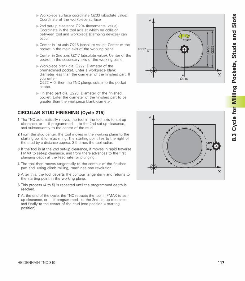
117HEIDENHAIN TNC 310
�Workpiece surface coordinate Q203 (absolute value):Coordinate of the workpiece surface
� 2nd set-up clearance Q204 (incremental value):Coordinate in the tool axis at which no collisionbetween tool and workpiece (clamping devices) canoccur.
�Center in 1st axis Q216 (absolute value): Center of thepocket in the main axis of the working plane
�Center in 2nd axis Q217 (absolute value): Center of thepocket in the secondary axis of the working plane
�Workpiece blank dia. Q222: Diameter of thepremachined pocket. Enter a workpiece blankdiameter less than the diameter of the finished part. Ifyou enterQ222 = 0, then the TNC plunge-cuts into the pocketcenter.
� Finished part dia. Q223: Diameter of the finishedpocket. Enter the diameter of the finished part to begreater than the workpiece blank diameter.
CIRCULAR STUD FINISHING (Cycle 215)
1 The TNC automatically moves the tool in the tool axis to set-upclearance, or — if programmed — to the 2nd set-up clearance,and subsequently to the center of the stud.
2 From the stud center, the tool moves in the working plane to thestarting point for machining. The starting point lies to the right ofthe stud by a distance approx. 3.5 times the tool radius.
3 If the tool is at the 2nd set-up clearance, it moves in rapid traverseFMAX to set-up clearance, and from there advances to the firstplunging depth at the feed rate for plunging.
4 The tool then moves tangentially to the contour of the finishedpart and, using climb milling, machines one revolution.
5 After this, the tool departs the contour tangentially and returns tothe starting point in the working plane.
6 This process (4 to 5) is repeated until the programmed depth isreached.
7 At the end of the cycle, the TNC retracts the tool in FMAX to set-up clearance, or — if programmed - to the 2nd set-up clearance,and finally to the center of the stud (end position = startingposition).
X
Y
Q22
2
Q217
Q216
Q207
Q22
3
X
Y
8.3
Cycle
fo
r M
illin
g P
ockets
, S
tud
s a
nd
Slo
ts
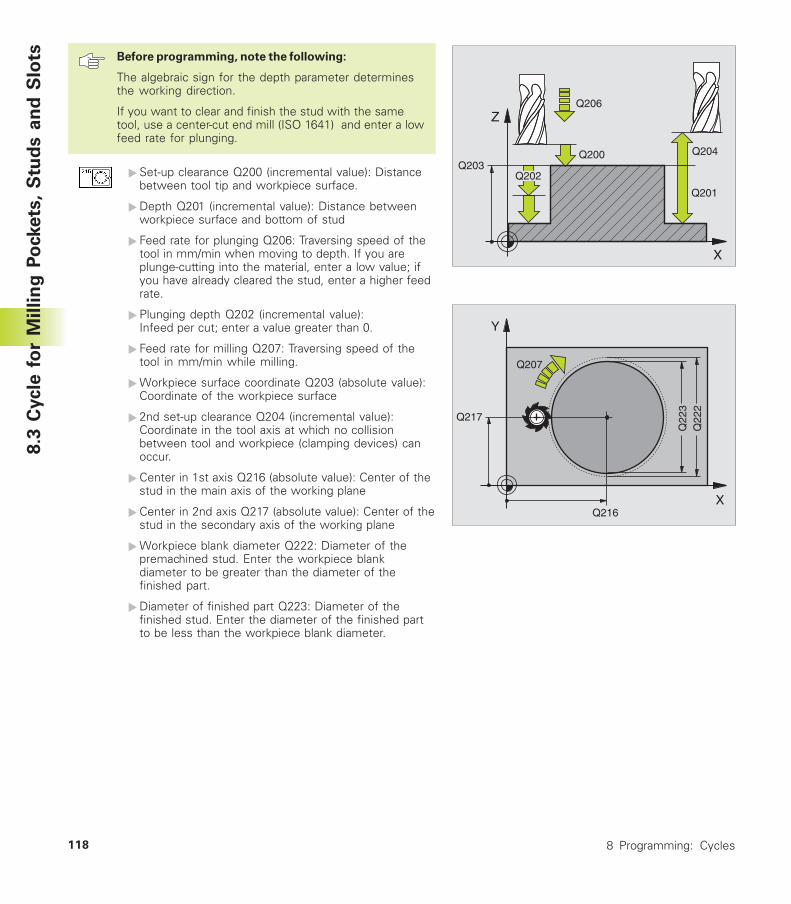
8 Programming: Cycles118
Before programming, note the following:
The algebraic sign for the depth parameter determinesthe working direction.
If you want to clear and finish the stud with the sametool, use a center-cut end mill (ISO 1641) and enter a lowfeed rate for plunging.
�Set-up clearance Q200 (incremental value): Distancebetween tool tip and workpiece surface.
�Depth Q201 (incremental value): Distance betweenworkpiece surface and bottom of stud
� Feed rate for plunging Q206: Traversing speed of thetool in mm/min when moving to depth. If you areplunge-cutting into the material, enter a low value; ifyou have already cleared the stud, enter a higher feedrate.
�Plunging depth Q202 (incremental value):Infeed per cut; enter a value greater than 0.
� Feed rate for milling Q207: Traversing speed of thetool in mm/min while milling.
�Workpiece surface coordinate Q203 (absolute value):Coordinate of the workpiece surface
� 2nd set-up clearance Q204 (incremental value):Coordinate in the tool axis at which no collisionbetween tool and workpiece (clamping devices) canoccur.
�Center in 1st axis Q216 (absolute value): Center of thestud in the main axis of the working plane
�Center in 2nd axis Q217 (absolute value): Center of thestud in the secondary axis of the working plane
�Workpiece blank diameter Q222: Diameter of thepremachined stud. Enter the workpiece blankdiameter to be greater than the diameter of thefinished part.
�Diameter of finished part Q223: Diameter of thefinished stud. Enter the diameter of the finished partto be less than the workpiece blank diameter.
8.3
Cycle
fo
r M
illin
g P
ockets
, S
tud
s a
nd
Slo
ts
X
Z
Q200
Q201
Q206
Q203Q204
Q202
X
Y
Q22
3
Q217
Q216
Q207
Q22
2
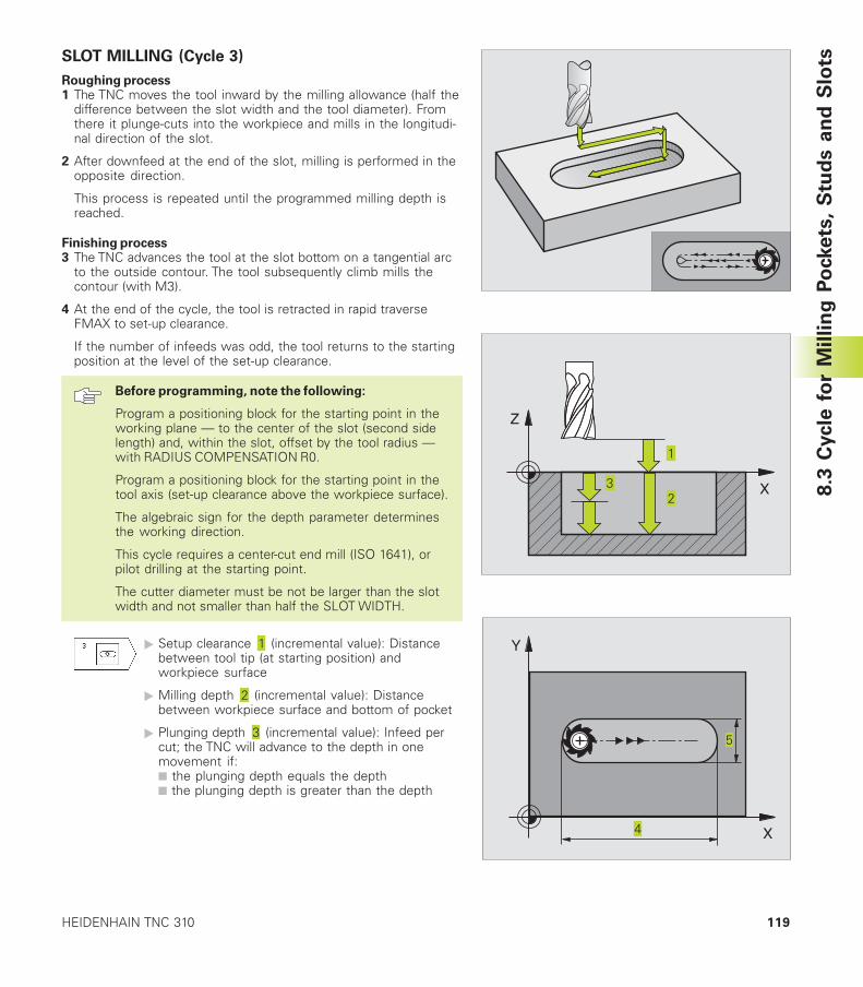
119HEIDENHAIN TNC 310
SLOT MILLING (Cycle 3)
Roughing process1 The TNC moves the tool inward by the milling allowance (half the
difference between the slot width and the tool diameter). Fromthere it plunge-cuts into the workpiece and mills in the longitudi-nal direction of the slot.
2 After downfeed at the end of the slot, milling is performed in theopposite direction.
This process is repeated until the programmed milling depth isreached.
Finishing process3 The TNC advances the tool at the slot bottom on a tangential arc
to the outside contour. The tool subsequently climb mills thecontour (with M3).
4 At the end of the cycle, the tool is retracted in rapid traverseFMAX to set-up clearance.
If the number of infeeds was odd, the tool returns to the startingposition at the level of the set-up clearance.
Before programming, note the following:
Program a positioning block for the starting point in theworking plane — to the center of the slot (second sidelength) and, within the slot, offset by the tool radius —with RADIUS COMPENSATION R0.
Program a positioning block for the starting point in thetool axis (set-up clearance above the workpiece surface).
The algebraic sign for the depth parameter determinesthe working direction.
This cycle requires a center-cut end mill (ISO 1641), orpilot drilling at the starting point.
The cutter diameter must be not be larger than the slotwidth and not smaller than half the SLOT WIDTH.
� Setup clearance (incremental value): Distancebetween tool tip (at starting position) andworkpiece surface
� Milling depth (incremental value): Distancebetween workpiece surface and bottom of pocket
� Plunging depth (incremental value): Infeed percut; the TNC will advance to the depth in onemovement if:■ the plunging depth equals the depth■ the plunging depth is greater than the depth
8.3
Cycle
fo
r M
illin
g P
ockets
, S
tud
s a
nd
Slo
ts
X
Z
X
Y
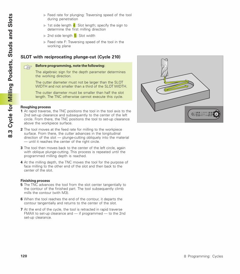
8 Programming: Cycles120
� Feed rate for plunging: Traversing speed of the toolduring penetration
� 1st side length : Slot length; specify the sign todetermine the first milling direction
� 2nd side length : Slot width
� Feed rate F: Traversing speed of the tool in theworking plane
SLOT with reciprocating plunge-cut (Cycle 210)
Before programming, note the following:
The algebraic sign for the depth parameter determinesthe working direction.
The cutter diameter must not be larger than the SLOTWIDTH and not smaller than a third of the SLOT WIDTH.
The cutter diameter must be smaller than half the slotlength. The TNC otherwise cannot execute this cycle.
Roughing process1 At rapid traverse, the TNC positions the tool in the tool axis to the
2nd set-up clearance and subsequently to the center of the leftcircle. From there, the TNC positions the tool to set-up clearanceabove the workpiece surface.
2 The tool moves at the feed rate for milling to the workpiecesurface. From there, the cutter advances in the longitudinaldirection of the slot — plunge-cutting obliquely into the material— until it reaches the center of the right circle.
3 The tool then moves back to the center of the left circle, againwith oblique plunge-cutting. This process is repeated until theprogrammed milling depth is reached.
4 At the milling depth, the TNC moves the tool for the purpose offace milling to the other end of the slot and then back to thecenter of the slot.
Finishing process5 The TNC advances the tool from the slot center tangentially to
the contour of the finished part. The tool subsequently climbmills the contour (with M3).
6 When the tool reaches the end of the contour, it departs thecontour tangentially and returns to the center of the slot.
7 At the end of the cycle, the tool is retracted in rapid traverseFMAX to set-up clearance and — if programmed — to the 2ndset-up clearance.
8.3
Cycle
fo
r M
illin
g P
ockets
, S
tud
s a
nd
Slo
ts
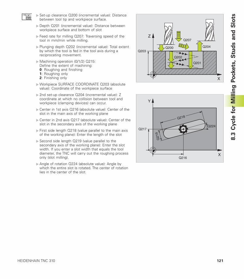
121HEIDENHAIN TNC 310
�Set-up clearance Q200 (incremental value): Distancebetween tool tip and workpiece surface.
�Depth Q201 (incremental value): Distance betweenworkpiece surface and bottom of slot
� Feed rate for milling Q207: Traversing speed of thetool in mm/min while milling.
�Plunging depth Q202 (incremental value): Total extentby which the tool is fed in the tool axis during areciprocating movement.
�Machining operation (0/1/2) Q215:Define the extent of machining:0: Roughing and finishing1: Roughing only2: Finishing only
�Workpiece SURFACE COORDINATE Q203 (absolutevalue): Coordinate of the workpiece surface
� 2nd set-up clearance Q204 (incremental value): Zcoordinate at which no collision between tool andworkpiece (clamping devices) can occur.
�Center in 1st axis Q216 (absolute value): Center of theslot in the main axis of the working plane
�Center in 2nd axis Q217 (absolute value): Center of theslot in the secondary axis of the working plane
� First side length Q218 (value parallel to the main axisof the working plane): Enter the length of the slot
�Second side length Q219 (value parallel to thesecondary axis of the working plane): Enter the slotwidth. If you enter a slot width that equals the tooldiameter, the TNC will carry out the roughing processonly (slot milling).
�Angle of rotation Q224 (absolute value): Angle bywhich the entire slot is rotated. The center of rotationlies in the center of the slot.
8.3
Cycle
fo
r M
illin
g P
ockets
, S
tud
s a
nd
Slo
ts
X
Z
Q200
Q201
Q207
Q202
Q203Q204
X
Y
Q21
9
Q218
Q217
Q216
Q224

8 Programming: Cycles122
CIRCULAR SLOT with reciprocating plunge-cut
(Cycle 211)
Roughing process1 At rapid traverse, the TNC positions the tool in the tool axis to the
2nd set-up clearance and subsequently to the center of the rightcircle. From there, the tool is positioned to the programmed set-up clearance above the workpiece surface.
2 The tool moves at the milling feed rate to the workpiece surface.From there, the cutter advances — plunge-cutting obliquely intothe material — to the other end of the slot.
3 The tool then moves at a downward angle back to the startingpoint, again with oblique plunge-cutting. This process (2 to 3) isrepeated until the programmed milling depth is reached.
4 At the milling depth, the TNC moves the tool for the purpose offace milling to the other end of the slot.
Finishing process5 For finishing the slot, the TNC advances the tool tangentially to
the contour of the finished part. The tool subsequently climb-mills the contour (with M3). The starting point for the finishingprocess is the center of the right circle.
6 When the tool reaches the end of the contour, it departs thecontour tangentially.
7 At the end of the cycle, the tool is retracted in rapid traverseFMAX to set-up clearance and — if programmed — to the 2ndset-up clearance.
Before programming, note the following:
The algebraic sign for the depth parameter determinesthe working direction.
The cutter diameter must not be larger than the slotwidth and not smaller than a third of the slot width.
The cutter diameter must be smaller than half the slotlength. The TNC otherwise cannot execute this cycle.
�Set-up clearance Q200 (incremental value): Distancebetween tool tip and workpiece surface.
�Depth Q201 (incremental value): Distance betweenworkpiece surface and bottom of slot
� Feed rate for milling Q207: Traversing speed of thetool in mm/min while milling.
�Plunging depth Q202 (incremental value): Total extentby which the tool is fed in the tool axis during areciprocating movement.
8.3
Cycle
fo
r M
illin
g P
ockets
, S
tud
s a
nd
Slo
ts
X
Z
Q200
Q207
Q202
Q203
Q204
Q201

123HEIDENHAIN TNC 310
8.3
Cycle
fo
r M
illin
g P
ockets
, S
tud
s a
nd
Slo
ts
X
Y
Q217
Q216
Q248
Q245Q219
Q244
�Machining operation (0/1/2) Q215:Define the extent of machining:0: Roughing and finishing1: Roughing only2: Finishing only
�Workpiece SURFACE COORDINATE Q203 (absolutevalue): Coordinate of the workpiece surface
� 2nd set-up clearance Q204 (incremental value): Zcoordinate at which no collision between tool andworkpiece (clamping devices) can occur.
�Center in 1st axis Q216 (absolute value): Center of theslot in the main axis of the working plane
�Center in 2nd axis Q217 (absolute value): Center of theslot in the secondary axis of the working plane
�Pitch circle diameter Q244: Enter the diameter of thepitch circle
�Second side length Q219: Enter the slot width. If youenter a slot width that equals the tool diameter, theTNC will carry out the roughing process only (slotmilling).
�Starting angle Q245 (absolute value): Enter the polarangle of the starting point.
�Angular length Q248 (incremental value): Enter theangular length of the slot
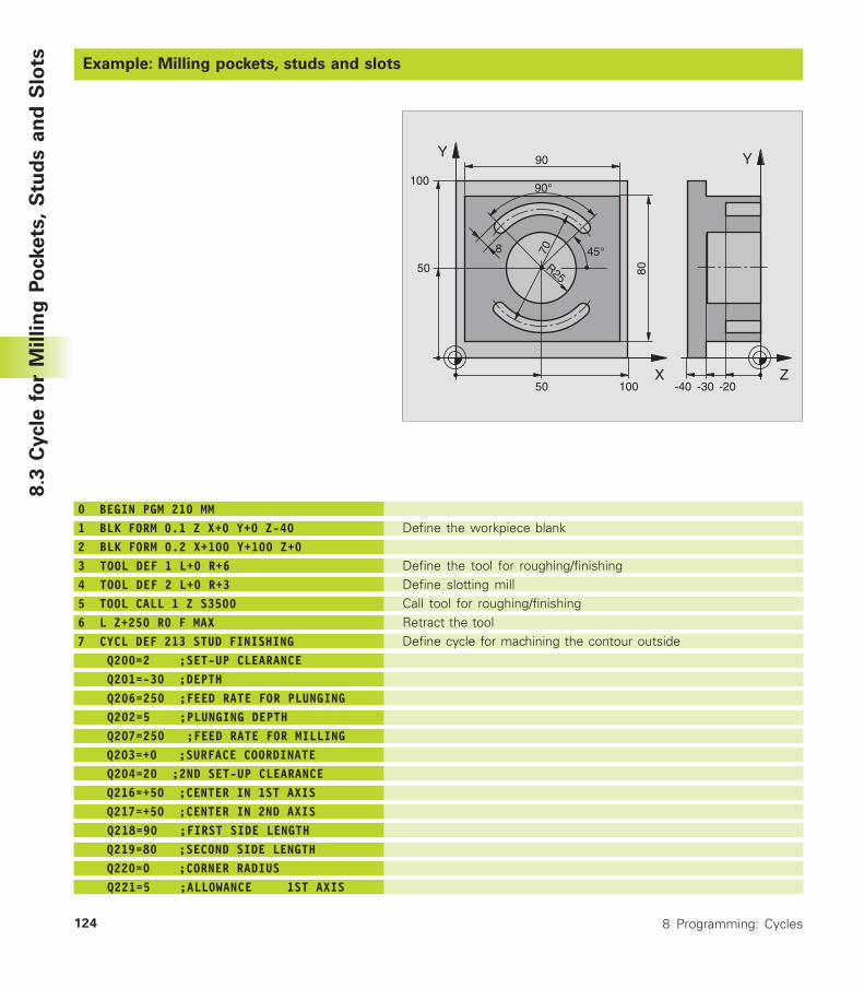
8 Programming: Cycles124
Example: Milling pockets, studs and slots
Define the workpiece blank
Define the tool for roughing/finishingDefine slotting millCall tool for roughing/finishingRetract the toolDefine cycle for machining the contour outside
0 BEGIN PGM 210 MM1 BLK FORM 0.1 Z X+0 Y+0 Z-402 BLK FORM 0.2 X+100 Y+100 Z+03 TOOL DEF 1 L+0 R+64 TOOL DEF 2 L+0 R+35 TOOL CALL 1 Z S35006 L Z+250 R0 F MAX7 CYCL DEF 213 STUD FINISHING Q200=2 ;SET-UP CLEARANCE Q201=-30 ;DEPTH Q206=250 ;FEED RATE FOR PLUNGING Q202=5 ;PLUNGING DEPTH Q207=250 ;FEED RATE FOR MILLING Q203=+0 ;SURFACE COORDINATE Q204=20 ;2ND SET-UP CLEARANCE Q216=+50 ;CENTER IN 1ST AXIS Q217=+50 ;CENTER IN 2ND AXIS Q218=90 ;FIRST SIDE LENGTH Q219=80 ;SECOND SIDE LENGTH Q220=0 ;CORNER RADIUS Q221=5 ;ALLOWANCE 1ST AXIS
8.3
Cycle
fo
r M
illin
g P
ockets
, S
tud
s a
nd
Slo
ts
X
Y
50
50
100
100
80
90
8
90°
45°R25
70
Z
Y
-40 -20-30
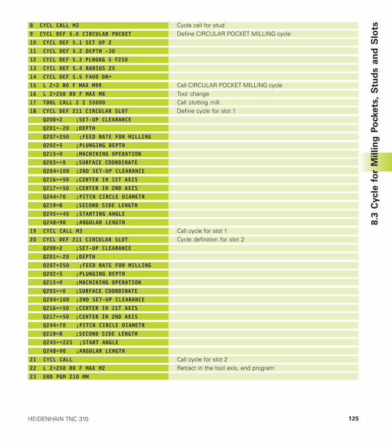
125HEIDENHAIN TNC 310
8 CYCL CALL M39 CYCL DEF 5.0 CIRCULAR POCKET10 CYCL DEF 5.1 SET UP 211 CYCL DEF 5.2 DEPTH -3012 CYCL DEF 5.3 PLNGNG 5 F25013 CYCL DEF 5.4 RADIUS 2514 CYCL DEF 5.5 F400 DR+15 L Z+2 R0 F MAX M9916 L Z+250 R0 F MAX M617 TOOL CALL 2 Z S500018 CYCL DEF 211 CIRCULAR SLOT Q200=2 ;SET-UP CLEARANCE Q201=-20 ;DEPTH Q207=250 ;FEED RATE FOR MILLING Q202=5 ;PLUNGING DEPTH Q215=0 ;MACHINING OPERATION Q203=+0 ;SURFACE COORDINATE Q204=100 ;2ND SET-UP CLEARANCE Q216=+50 ;CENTER IN 1ST AXIS Q217=+50 ;CENTER IN 2ND AXIS Q244=70 ;PITCH CIRCLE DIAMETR Q219=8 ;SECOND SIDE LENGTH Q245=+45 ;STARTING ANGLE Q248=90 ;ANGULAR LENGTH19 CYCL CALL M320 CYCL DEF 211 CIRCULAR SLOT Q200=2 ;SET-UP CLEARANCE Q201=-20 ;DEPTH Q207=250 ;FEED RATE FOR MILLING Q202=5 ;PLUNGING DEPTH Q215=0 ;MACHINING OPERATION Q203=+0 ;SURFACE COORDINATE Q204=100 ;2ND SET-UP CLEARANCE Q216=+50 ;CENTER IN 1ST AXIS Q217=+50 ;CENTER IN 2ND AXIS Q244=70 ;PITCH CIRCLE DIAMETR Q219=8 ;SECOND SIDE LENGTH Q245=+225 ;START ANGLE Q248=90 ;ANGULAR LENGTH21 CYCL CALL22 L Z+250 R0 F MAX M223 END PGM 210 MM
Cycle call for studDefine CIRCULAR POCKET MILLING cycle
Call CIRCULAR POCKET MILLING cycleTool changeCall slotting millDefine cycle for slot 1
Call cycle for slot 1Cycle definition for slot 2
Call cycle for slot 2Retract in the tool axis, end program
8.3
Cycle
fo
r M
illin
g P
ockets
, S
tud
s a
nd
Slo
ts
8 Programming: Cycles126
8.4 Cycles for Machining Hole Patterns
The TNC provides two cycles for machining hole patterns:
Cycle Soft key
220 CIRCULAR PATTERN
221 LINEAR PATTERN
You can combine Cycle 220 and Cycle 221 with the following fixedcycles:
Cycle 1 PECKINGCycle 2 TAPPING with a floating tap holderCycle 3 SLOT MILLINGCycle 4 POCKET MILLINGCycle 5 CIRCULAR POCKET MILLINGCycle 17 RIGID TAPPING
Cycle 200 DRILLINGCycle 201 REAMINGCycle 202 BORINGCycle 203 UNIVERSAL MILLING CYCLECycle 204 BACK BORINGCycle 212 POCKET FINISHINGCycle 213 STUD FINISHINGCycle 214 CIRCULAR POCKET FINISHINGCycle 215 CIRCULAR STUD FINISHING
8.4
Cycle
s f
or
Mach
inin
g H
ole
Patt
ern
s
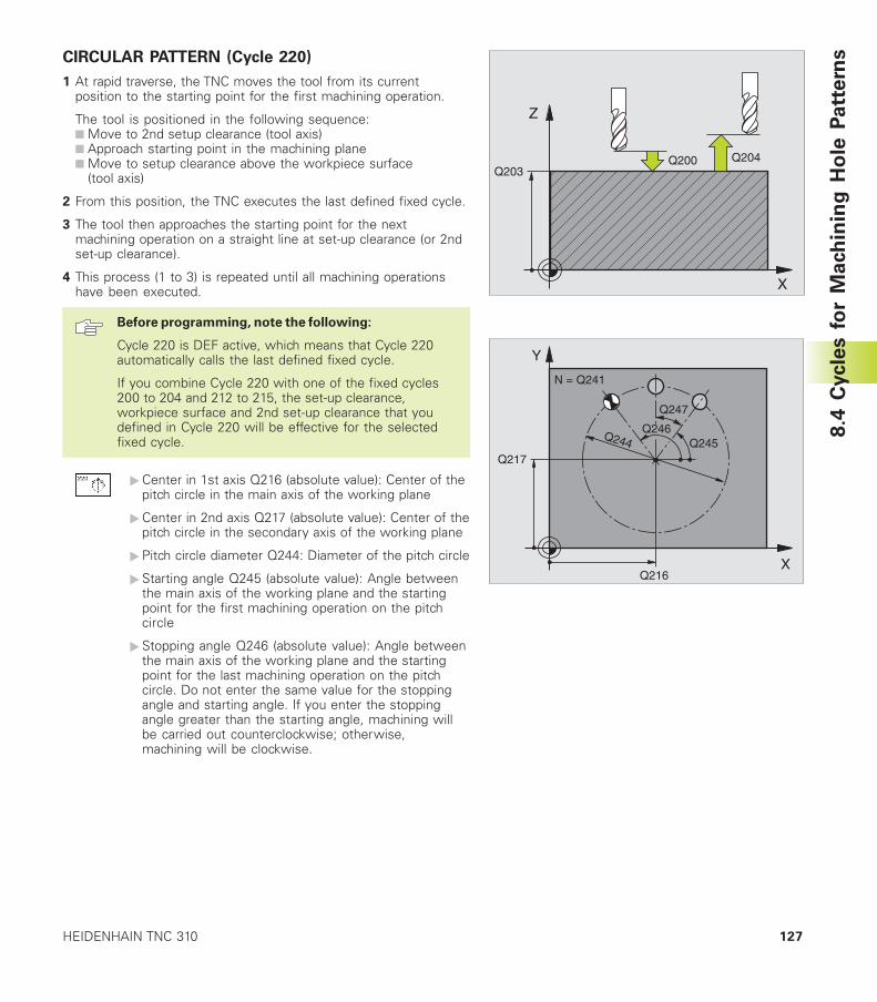
127HEIDENHAIN TNC 310
CIRCULAR PATTERN (Cycle 220)
1 At rapid traverse, the TNC moves the tool from its currentposition to the starting point for the first machining operation.
The tool is positioned in the following sequence:■ Move to 2nd setup clearance (tool axis)■ Approach starting point in the machining plane■ Move to setup clearance above the workpiece surface
(tool axis)
2 From this position, the TNC executes the last defined fixed cycle.
3 The tool then approaches the starting point for the nextmachining operation on a straight line at set-up clearance (or 2ndset-up clearance).
4 This process (1 to 3) is repeated until all machining operationshave been executed.
Before programming, note the following:
Cycle 220 is DEF active, which means that Cycle 220automatically calls the last defined fixed cycle.
If you combine Cycle 220 with one of the fixed cycles200 to 204 and 212 to 215, the set-up clearance,workpiece surface and 2nd set-up clearance that youdefined in Cycle 220 will be effective for the selectedfixed cycle.
�Center in 1st axis Q216 (absolute value): Center of thepitch circle in the main axis of the working plane
�Center in 2nd axis Q217 (absolute value): Center of thepitch circle in the secondary axis of the working plane
�Pitch circle diameter Q244: Diameter of the pitch circle
�Starting angle Q245 (absolute value): Angle betweenthe main axis of the working plane and the startingpoint for the first machining operation on the pitchcircle
�Stopping angle Q246 (absolute value): Angle betweenthe main axis of the working plane and the startingpoint for the last machining operation on the pitchcircle. Do not enter the same value for the stoppingangle and starting angle. If you enter the stoppingangle greater than the starting angle, machining willbe carried out counterclockwise; otherwise,machining will be clockwise.
8.4
Cycle
s f
or
Mach
inin
g H
ole
Patt
ern
s
X
Z
Q200Q203
Q204
X
Y
Q217
Q216
Q247
Q245Q244
Q246
N = Q241
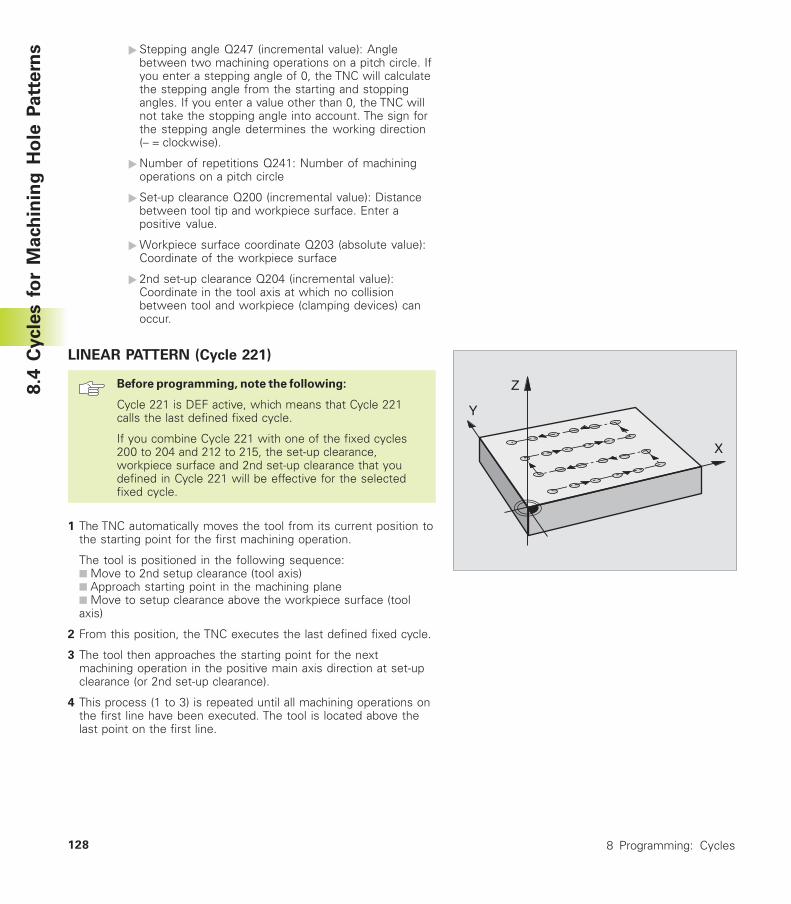
8 Programming: Cycles128
�Stepping angle Q247 (incremental value): Anglebetween two machining operations on a pitch circle. Ifyou enter a stepping angle of 0, the TNC will calculatethe stepping angle from the starting and stoppingangles. If you enter a value other than 0, the TNC willnot take the stopping angle into account. The sign forthe stepping angle determines the working direction(– = clockwise).
�Number of repetitions Q241: Number of machiningoperations on a pitch circle
�Set-up clearance Q200 (incremental value): Distancebetween tool tip and workpiece surface. Enter apositive value.
�Workpiece surface coordinate Q203 (absolute value):Coordinate of the workpiece surface
� 2nd set-up clearance Q204 (incremental value):Coordinate in the tool axis at which no collisionbetween tool and workpiece (clamping devices) canoccur.
LINEAR PATTERN (Cycle 221)
Before programming, note the following:
Cycle 221 is DEF active, which means that Cycle 221calls the last defined fixed cycle.
If you combine Cycle 221 with one of the fixed cycles200 to 204 and 212 to 215, the set-up clearance,workpiece surface and 2nd set-up clearance that youdefined in Cycle 221 will be effective for the selectedfixed cycle.
1 The TNC automatically moves the tool from its current position tothe starting point for the first machining operation.
The tool is positioned in the following sequence:■ Move to 2nd setup clearance (tool axis)■ Approach starting point in the machining plane■ Move to setup clearance above the workpiece surface (toolaxis)
2 From this position, the TNC executes the last defined fixed cycle.
3 The tool then approaches the starting point for the nextmachining operation in the positive main axis direction at set-upclearance (or 2nd set-up clearance).
4 This process (1 to 3) is repeated until all machining operations onthe first line have been executed. The tool is located above thelast point on the first line.
X
Y
Z8.4
Cycle
s f
or
Mach
inin
g H
ole
Patt
ern
s
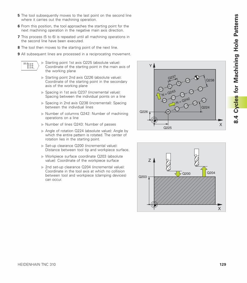
129HEIDENHAIN TNC 310
5 The tool subsequently moves to the last point on the second linewhere it carries out the machining operation.
6 From this position, the tool approaches the starting point for thenext machining operation in the negative main axis direction.
7 This process (5 to 6) is repeated until all machining operations inthe second line have been executed.
8 The tool then moves to the starting point of the next line.
9 All subsequent lines are processed in a reciprocating movement.
� Starting point 1st axis Q225 (absolute value):Coordinate of the starting point in the main axis ofthe working plane
� Starting point 2nd axis Q226 (absolute value):Coordinate of the starting point in the secondaryaxis of the working plane
� Spacing in 1st axis Q237 (incremental value):Spacing between the individual points on a line
� Spacing in 2nd axis Q238 (incremental): Spacingbetween the individual lines
� Number of columns Q242: Number of machiningoperations on a line
� Number of lines Q243: Number of passes
� Angle of rotation Q224 (absolute value): Angle bywhich the entire pattern is rotated. The center ofrotation lies in the starting point.
� Set-up clearance Q200 (incremental value):Distance between tool tip and workpiece surface.
� Workpiece surface coordinate Q203 (absolutevalue): Coordinate of the workpiece surface
� 2nd set-up clearance Q204 (incremental value):Coordinate in the tool axis at which no collisionbetween tool and workpiece (clamping devices)can occur.
8.4
Cycle
s f
or
Mach
inin
g H
ole
Patt
ern
s
X
Z
Q200Q203
Q204
X
Y
Q226
Q225
Q224
Q238Q237
N = Q242N = Q243
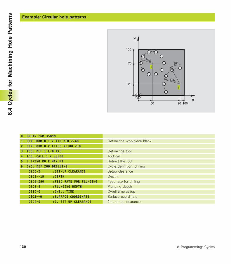
8 Programming: Cycles130
Example: Circular hole patterns
Define the workpiece blank
Define the toolTool callRetract the toolCycle definition: drillingSetup clearanceDepthFeed rate for drillingPlunging depthDwell time at topSurface coordinate2nd set-up clearance
0 BEGIN PGM 3589M1 BLK FORM 0.1 Z X+0 Y+0 Z-402 BLK FORM 0.2 X+100 Y+100 Z+03 TOOL DEF 1 L+0 R+34 TOOL CALL 1 Z S35005 L Z+250 R0 F MAX M36 CYCL DEF 200 DRILLING Q200=2 ;SET-UP CLEARANCE Q201=-15 ;DEPTH Q206=250 ;FEED RATE FOR PLUNGING Q202=4 ;PLUNGING DEPTH Q210=0 ;DWELL TIME Q203=+0 ;SURFACE COORDINATE Q204=0 ;2. SET-UP CLEARANCE
8.4
Cycle
s f
or
Mach
inin
g H
ole
Patt
ern
s
X
Y
30
70
100
100
R25
R35
30°
90
25
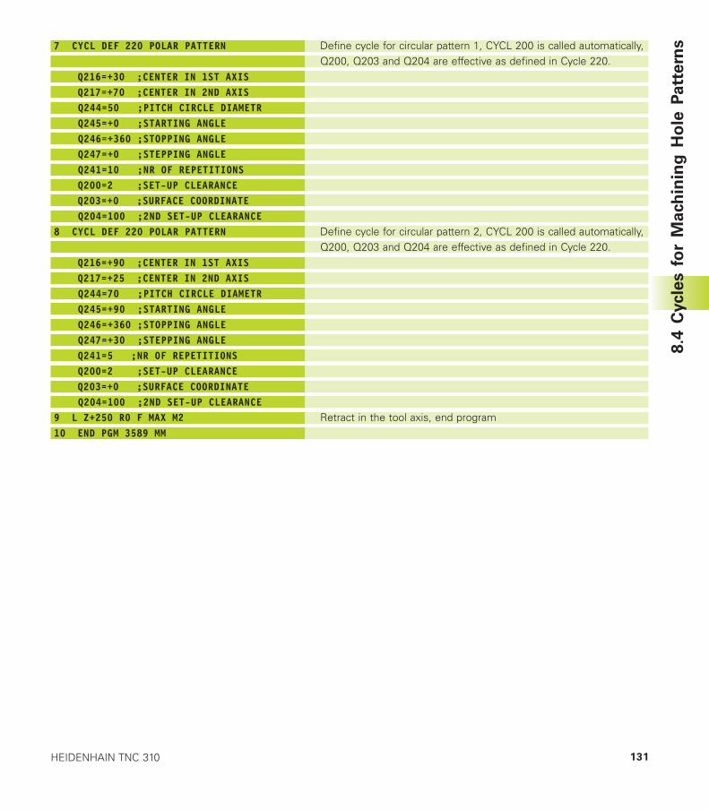
131HEIDENHAIN TNC 310
7 CYCL DEF 220 POLAR PATTERN
Q216=+30 ;CENTER IN 1ST AXIS Q217=+70 ;CENTER IN 2ND AXIS Q244=50 ;PITCH CIRCLE DIAMETR Q245=+0 ;STARTING ANGLE Q246=+360 ;STOPPING ANGLE Q247=+0 ;STEPPING ANGLE Q241=10 ;NR OF REPETITIONS Q200=2 ;SET-UP CLEARANCE Q203=+0 ;SURFACE COORDINATE Q204=100 ;2ND SET-UP CLEARANCE8 CYCL DEF 220 POLAR PATTERN
Q216=+90 ;CENTER IN 1ST AXIS Q217=+25 ;CENTER IN 2ND AXIS Q244=70 ;PITCH CIRCLE DIAMETR Q245=+90 ;STARTING ANGLE Q246=+360 ;STOPPING ANGLE Q247=+30 ;STEPPING ANGLE Q241=5 ;NR OF REPETITIONS Q200=2 ;SET-UP CLEARANCE Q203=+0 ;SURFACE COORDINATE Q204=100 ;2ND SET-UP CLEARANCE9 L Z+250 R0 F MAX M210 END PGM 3589 MM
Define cycle for circular pattern 1, CYCL 200 is called automatically,Q200, Q203 and Q204 are effective as defined in Cycle 220.
Define cycle for circular pattern 2, CYCL 200 is called automatically,Q200, Q203 and Q204 are effective as defined in Cycle 220.
Retract in the tool axis, end program
8.4
Cycle
s f
or
Mach
inin
g H
ole
Patt
ern
s
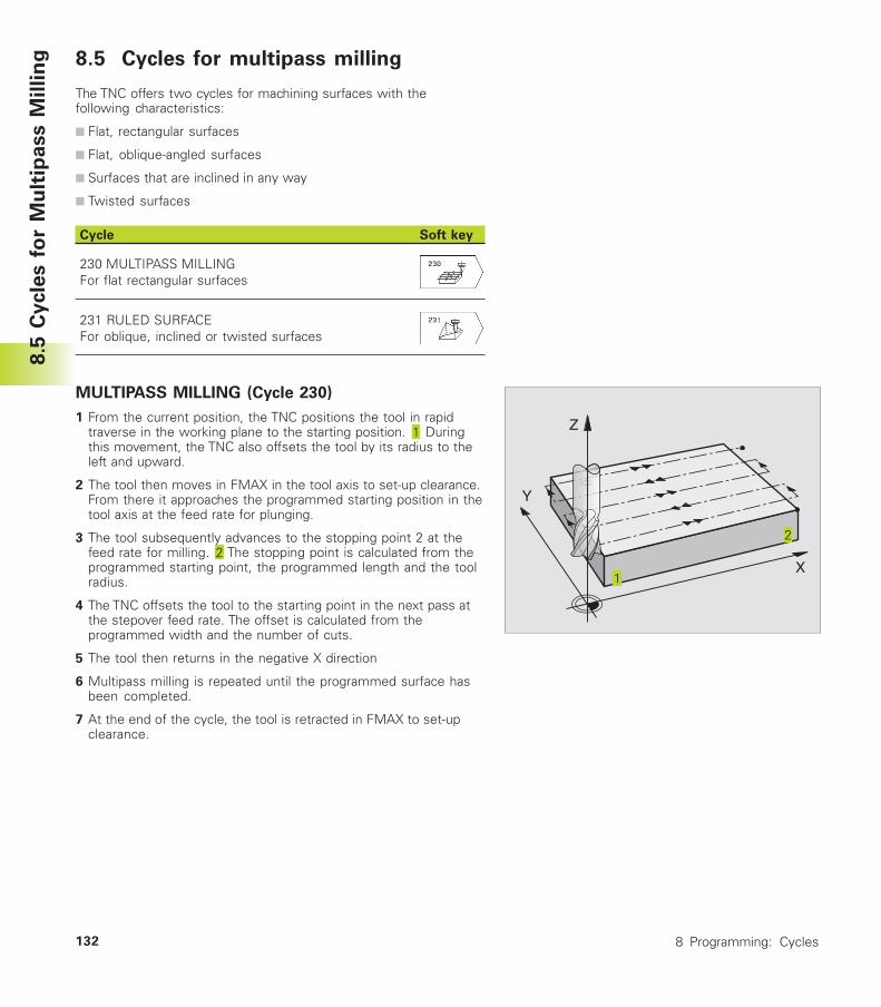
8 Programming: Cycles132
X
Y
Z
8.5 Cycles for multipass milling
The TNC offers two cycles for machining surfaces with thefollowing characteristics:
■ Flat, rectangular surfaces
■ Flat, oblique-angled surfaces
■ Surfaces that are inclined in any way
■ Twisted surfaces
Cycle Soft key
230 MULTIPASS MILLINGFor flat rectangular surfaces
231 RULED SURFACEFor oblique, inclined or twisted surfaces
MULTIPASS MILLING (Cycle 230)
1 From the current position, the TNC positions the tool in rapidtraverse in the working plane to the starting position. Duringthis movement, the TNC also offsets the tool by its radius to theleft and upward.
2 The tool then moves in FMAX in the tool axis to set-up clearance.From there it approaches the programmed starting position in thetool axis at the feed rate for plunging.
3 The tool subsequently advances to the stopping point 2 at thefeed rate for milling. The stopping point is calculated from theprogrammed starting point, the programmed length and the toolradius.
4 The TNC offsets the tool to the starting point in the next pass atthe stepover feed rate. The offset is calculated from theprogrammed width and the number of cuts.
5 The tool then returns in the negative X direction
6 Multipass milling is repeated until the programmed surface hasbeen completed.
7 At the end of the cycle, the tool is retracted in FMAX to set-upclearance.
8.5
Cycle
s f
or
Mu
ltip
ass M
illin
g
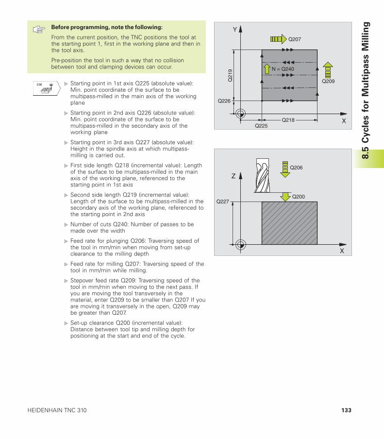
133HEIDENHAIN TNC 310
Before programming, note the following:
From the current position, the TNC positions the tool atthe starting point 1, first in the working plane and then inthe tool axis.
Pre-position the tool in such a way that no collisionbetween tool and clamping devices can occur.
� Starting point in 1st axis Q225 (absolute value):Min. point coordinate of the surface to bemultipass-milled in the main axis of the workingplane
� Starting point in 2nd axis Q226 (absolute value):Min. point coordinate of the surface to bemultipass-milled in the secondary axis of theworking plane
� Starting point in 3rd axis Q227 (absolute value):Height in the spindle axis at which multipass-milling is carried out.
� First side length Q218 (incremental value): Lengthof the surface to be multipass-milled in the mainaxis of the working plane, referenced to thestarting point in 1st axis
� Second side length Q219 (incremental value):Length of the surface to be multipass-milled in thesecondary axis of the working plane, referenced tothe starting point in 2nd axis
� Number of cuts Q240: Number of passes to bemade over the width
� Feed rate for plunging Q206: Traversing speed ofthe tool in mm/min when moving from set-upclearance to the milling depth
� Feed rate for milling Q207: Traversing speed of thetool in mm/min while milling.
� Stepover feed rate Q209: Traversing speed of thetool in mm/min when moving to the next pass. Ifyou are moving the tool transversely in thematerial, enter Q209 to be smaller than Q207 If youare moving it transversely in the open, Q209 maybe greater than Q207.
� Set-up clearance Q200 (incremental value):Distance between tool tip and milling depth forpositioning at the start and end of the cycle.
8.5
Cycle
s f
or
Mu
ltip
ass M
illin
g
X
Z
Q200Q227
Q206
X
Y
Q226
Q225
Q21
9
Q218
Q207
Q209
N = Q240

8 Programming: Cycles134
RULED SURFACE (Cycle 231)
1 From the current position, the TNC positions the tool in a linear 3-D movement to the starting point .
2 The tool subsequently advances to the stopping point at thefeed rate for milling.
3 From this point, the tool moves in rapid traverse FMAX by the tooldiameter in the positive tool axis direction, and then back tostarting point .
4 At the starting position the TNC moves the tool back to the thelast traversed Z value.
5 Then the TNC moves the tool in all three axes from point in thedirection of point to the next line.
6 From this point, the tool moves to the stopping point on thispass. The TNC calculates the stopping point using point and anoffset in the direction of point
7 Multipass milling is repeated until the programmed surface hasbeen completed.
8 At the end of the cycle, the tool is positioned above the highestprogrammed point in the tool axis, offset by the tool diameter.
Cutting motionYou can freely choose the starting point and thus the millingdirection since the TNC always performs the individual cuts frompoint to point and the process sequence is executed frompoint / to point / . You can position point in any corner ofthe surface to be machined.
If you are using an end mill for the machining operation, you canoptimize the surface finish in the following ways
■ a shaping cut (tool axis coordinate of point greater than toolaxis coordinate of point ) for slightly inclined surfaces.
■ a drawing cut (tool axis coordinate of point less than tool axiscoordinate of point ) for steep surfaces
■ When milling twisted surfaces, program the main cuttingdirection (from point to point ) parallel to the direction of thesteeper inclination. See figure at center right.
If you are using a spherical cutter for the machining operation, youcan optimize the surface finish in the following way
■ When milling twisted surfaces, program the main cuttingdirection (from point to point ) perpendicular to the directionof the steeper inclination. See figure at lower right.
8.5
Cycle
s f
or
Mu
ltip
ass M
illin
g
X
Y
Z
X
Y
Z
X
Y
Z
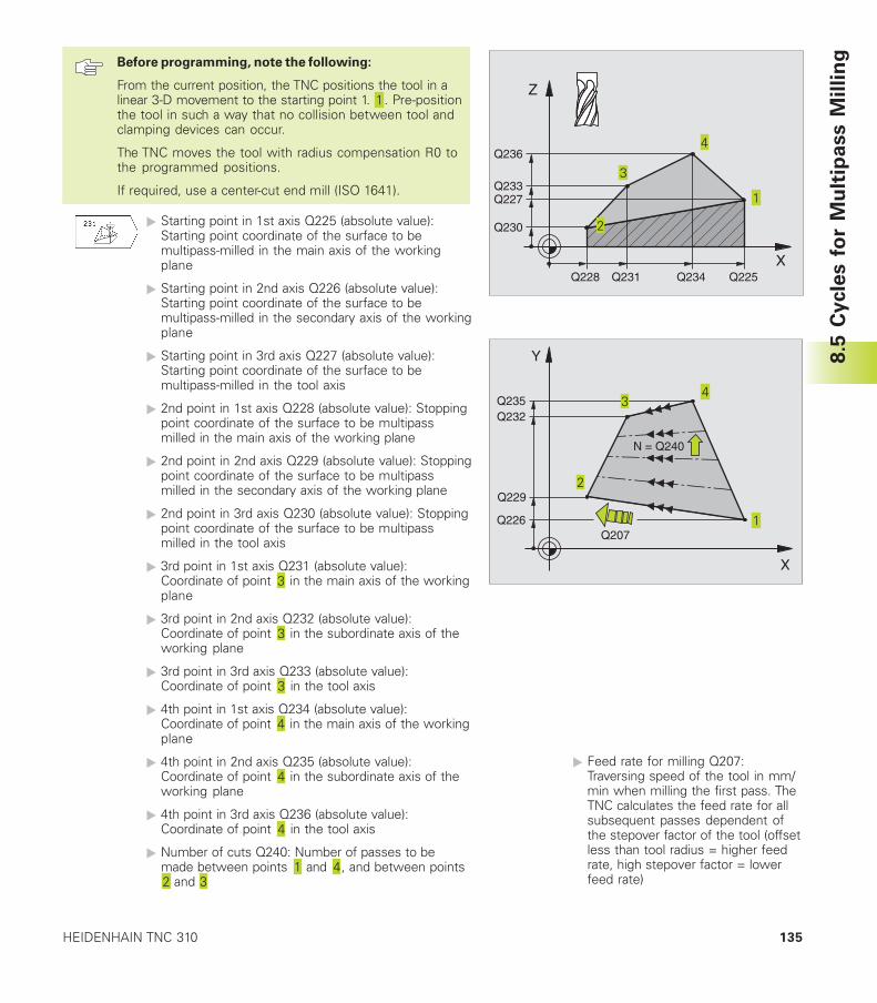
135HEIDENHAIN TNC 310
Before programming, note the following:
From the current position, the TNC positions the tool in alinear 3-D movement to the starting point 1. . Pre-positionthe tool in such a way that no collision between tool andclamping devices can occur.
The TNC moves the tool with radius compensation R0 tothe programmed positions.
If required, use a center-cut end mill (ISO 1641).
� Starting point in 1st axis Q225 (absolute value):Starting point coordinate of the surface to bemultipass-milled in the main axis of the workingplane
� Starting point in 2nd axis Q226 (absolute value):Starting point coordinate of the surface to bemultipass-milled in the secondary axis of the workingplane
� Starting point in 3rd axis Q227 (absolute value):Starting point coordinate of the surface to bemultipass-milled in the tool axis
� 2nd point in 1st axis Q228 (absolute value): Stoppingpoint coordinate of the surface to be multipassmilled in the main axis of the working plane
� 2nd point in 2nd axis Q229 (absolute value): Stoppingpoint coordinate of the surface to be multipassmilled in the secondary axis of the working plane
� 2nd point in 3rd axis Q230 (absolute value): Stoppingpoint coordinate of the surface to be multipassmilled in the tool axis
� 3rd point in 1st axis Q231 (absolute value):Coordinate of point in the main axis of the workingplane
� 3rd point in 2nd axis Q232 (absolute value):Coordinate of point in the subordinate axis of theworking plane
� 3rd point in 3rd axis Q233 (absolute value):Coordinate of point in the tool axis
� 4th point in 1st axis Q234 (absolute value):Coordinate of point in the main axis of the workingplane
� 4th point in 2nd axis Q235 (absolute value):Coordinate of point in the subordinate axis of theworking plane
� 4th point in 3rd axis Q236 (absolute value):Coordinate of point in the tool axis
� Number of cuts Q240: Number of passes to bemade between points and , and between points
and
8.5
Cycle
s f
or
Mu
ltip
ass M
illin
g
X
Y
Q229
Q207
N = Q240
Q226
Q232Q235
X
Z
Q236
Q233Q227
Q230
Q228 Q225Q234Q231
� Feed rate for milling Q207:Traversing speed of the tool in mm/min when milling the first pass. TheTNC calculates the feed rate for allsubsequent passes dependent ofthe stepover factor of the tool (offsetless than tool radius = higher feedrate, high stepover factor = lowerfeed rate)
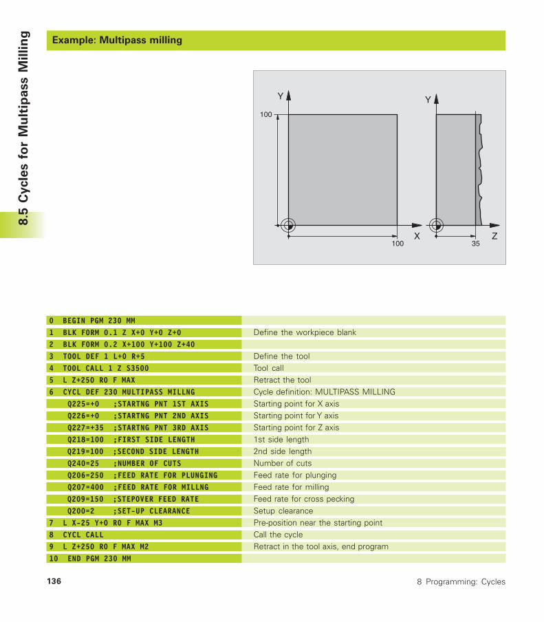
8 Programming: Cycles136
Example: Multipass milling
Define the workpiece blank
Define the toolTool callRetract the toolCycle definition: MULTIPASS MILLINGStarting point for X axisStarting point for Y axisStarting point for Z axis1st side length2nd side lengthNumber of cutsFeed rate for plungingFeed rate for millingFeed rate for cross peckingSetup clearancePre-position near the starting pointCall the cycleRetract in the tool axis, end program
0 BEGIN PGM 230 MM1 BLK FORM 0.1 Z X+0 Y+0 Z+02 BLK FORM 0.2 X+100 Y+100 Z+403 TOOL DEF 1 L+0 R+54 TOOL CALL 1 Z S35005 L Z+250 R0 F MAX6 CYCL DEF 230 MULTIPASS MILLNG Q225=+0 ;STARTNG PNT 1ST AXIS Q226=+0 ;STARTNG PNT 2ND AXIS Q227=+35 ;STARTNG PNT 3RD AXIS Q218=100 ;FIRST SIDE LENGTH Q219=100 ;SECOND SIDE LENGTH Q240=25 ;NUMBER OF CUTS Q206=250 ;FEED RATE FOR PLUNGING Q207=400 ;FEED RATE FOR MILLNG Q209=150 ;STEPOVER FEED RATE Q200=2 ;SET-UP CLEARANCE7 L X-25 Y+0 R0 F MAX M38 CYCL CALL9 L Z+250 R0 F MAX M210 END PGM 230 MM
8.5
Cycle
s f
or
Mu
ltip
ass M
illin
g
X
Y
100
100
Z
Y
35
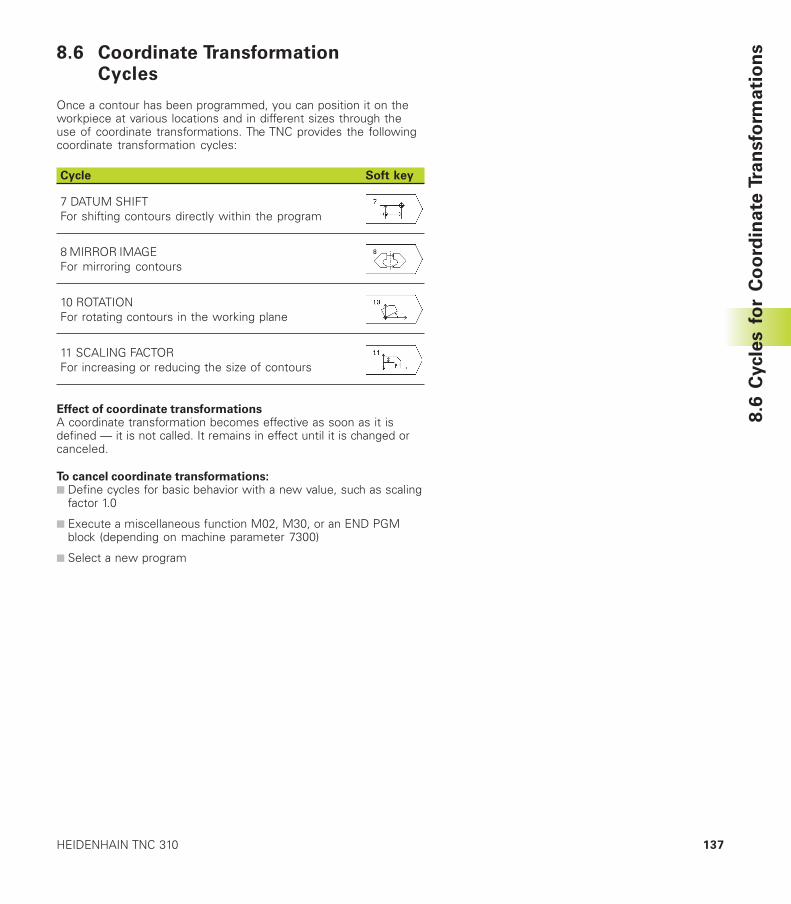
137HEIDENHAIN TNC 310
8.6 Coordinate TransformationCycles
Once a contour has been programmed, you can position it on theworkpiece at various locations and in different sizes through theuse of coordinate transformations. The TNC provides the followingcoordinate transformation cycles:
Cycle Soft key
7 DATUM SHIFTFor shifting contours directly within the program
8 MIRROR IMAGEFor mirroring contours
10 ROTATIONFor rotating contours in the working plane
11 SCALING FACTORFor increasing or reducing the size of contours
Effect of coordinate transformationsA coordinate transformation becomes effective as soon as it isdefined — it is not called. It remains in effect until it is changed orcanceled.
To cancel coordinate transformations:■ Define cycles for basic behavior with a new value, such as scaling
factor 1.0
■ Execute a miscellaneous function M02, M30, or an END PGMblock (depending on machine parameter 7300)
■ Select a new program
8.6
Cycle
s f
or
Co
ord
ina
te T
ran
sfo
rma
tio
ns
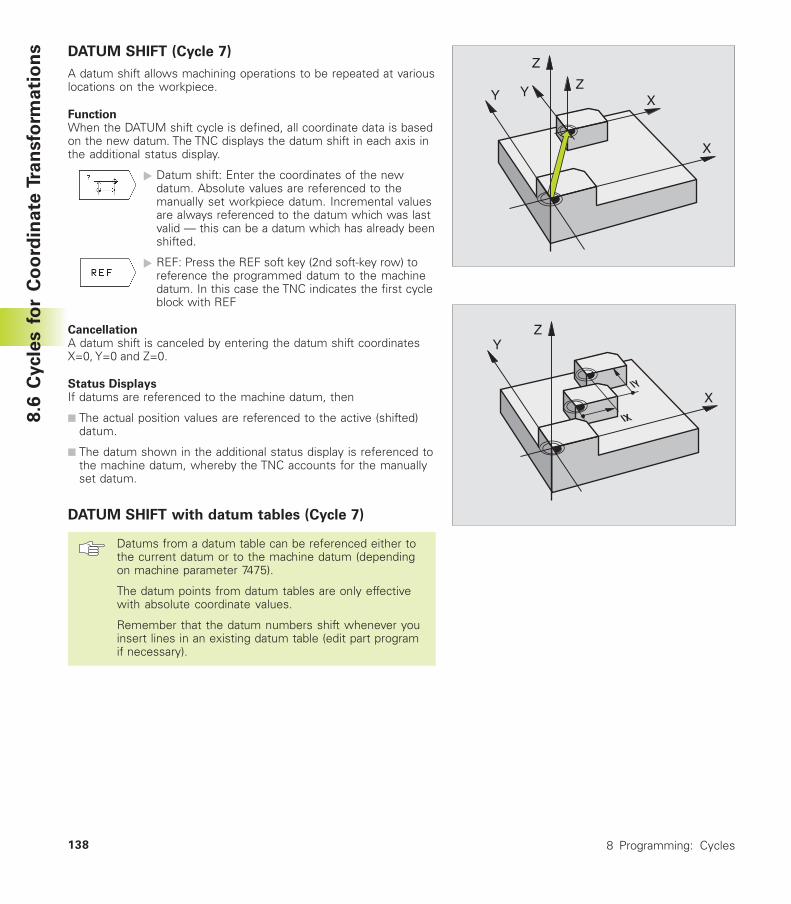
8 Programming: Cycles138
DATUM SHIFT (Cycle 7)
A datum shift allows machining operations to be repeated at variouslocations on the workpiece.
FunctionWhen the DATUM shift cycle is defined, all coordinate data is basedon the new datum. The TNC displays the datum shift in each axis inthe additional status display.
� Datum shift: Enter the coordinates of the newdatum. Absolute values are referenced to themanually set workpiece datum. Incremental valuesare always referenced to the datum which was lastvalid — this can be a datum which has already beenshifted.
� REF: Press the REF soft key (2nd soft-key row) toreference the programmed datum to the machinedatum. In this case the TNC indicates the first cycleblock with REF
CancellationA datum shift is canceled by entering the datum shift coordinatesX=0, Y=0 and Z=0.
Status DisplaysIf datums are referenced to the machine datum, then
■ The actual position values are referenced to the active (shifted)datum.
■ The datum shown in the additional status display is referenced tothe machine datum, whereby the TNC accounts for the manuallyset datum.
DATUM SHIFT with datum tables (Cycle 7)
Datums from a datum table can be referenced either tothe current datum or to the machine datum (dependingon machine parameter 7475).
The datum points from datum tables are only effectivewith absolute coordinate values.
Remember that the datum numbers shift whenever youinsert lines in an existing datum table (edit part programif necessary).
8.6
Cycle
s f
or
Co
ord
ina
te T
ran
sfo
rma
tio
ns
Z
Z
X
XY Y
Z
X
Y
IX
IY
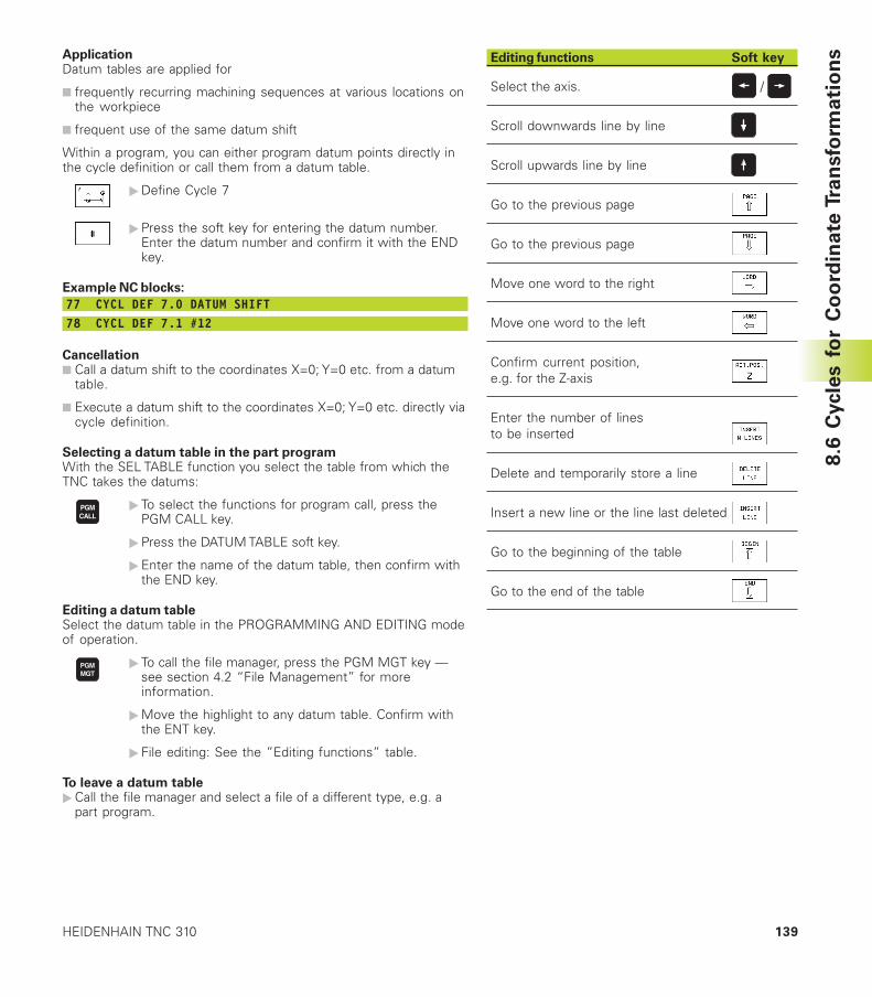
139HEIDENHAIN TNC 310
8.6
Cycle
s f
or
Co
ord
ina
te T
ran
sfo
rma
tio
nsApplication
Datum tables are applied for
■ frequently recurring machining sequences at various locations onthe workpiece
■ frequent use of the same datum shift
Within a program, you can either program datum points directly inthe cycle definition or call them from a datum table.
�Define Cycle 7
�Press the soft key for entering the datum number.Enter the datum number and confirm it with the ENDkey.
Example NC blocks:
77 CYCL DEF 7.0 DATUM SHIFT78 CYCL DEF 7.1 #12
Cancellation■ Call a datum shift to the coordinates X=0; Y=0 etc. from a datum
table.
■ Execute a datum shift to the coordinates X=0; Y=0 etc. directly viacycle definition.
Selecting a datum table in the part programWith the SEL TABLE function you select the table from which theTNC takes the datums:
� To select the functions for program call, press thePGM CALL key.
�Press the DATUM TABLE soft key.
�Enter the name of the datum table, then confirm withthe END key.
Editing a datum tableSelect the datum table in the PROGRAMMING AND EDITING modeof operation.
� To call the file manager, press the PGM MGT key —see section 4.2 “File Management” for moreinformation.
�Move the highlight to any datum table. Confirm withthe ENT key.
� File editing: See the ”Editing functions” table.
To leave a datum table�Call the file manager and select a file of a different type, e.g. a
part program.
Editing functions Soft key
Select the axis. /
Scroll downwards line by line
Scroll upwards line by line
Go to the previous page
Go to the previous page
Move one word to the right
Move one word to the left
Confirm current position,e.g. for the Z-axis
Enter the number of linesto be inserted
Delete and temporarily store a line
Insert a new line or the line last deleted
Go to the beginning of the table
Go to the end of the table
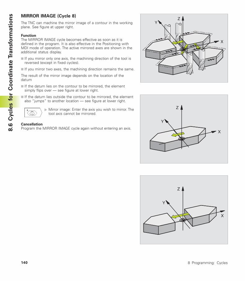
8 Programming: Cycles140
8.6
Cycle
s f
or
Co
ord
ina
te T
ran
sfo
rma
tio
ns
Y
X
Z
Y
X
Z
Y
X
Z
MIRROR IMAGE (Cycle 8)
The TNC can machine the mirror image of a contour in the workingplane. See figure at upper right.
FunctionThe MIRROR IMAGE cycle becomes effective as soon as it isdefined in the program. It is also effective in the Positioning withMDI mode of operation. The active mirrored axes are shown in theadditional status display.
■ If you mirror only one axis, the machining direction of the tool isreversed (except in fixed cycles).
■ If you mirror two axes, the machining direction remains the same.
The result of the mirror image depends on the location of thedatum
■ If the datum lies on the contour to be mirrored, the elementsimply flips over — see figure at lower right.
■ If the datum lies outside the contour to be mirrored, the elementalso “jumps” to another location — see figure at lower right.
� Mirror image: Enter the axis you wish to mirror. Thetool axis cannot be mirrored.
CancellationProgram the MIRROR IMAGE cycle again without entering an axis.
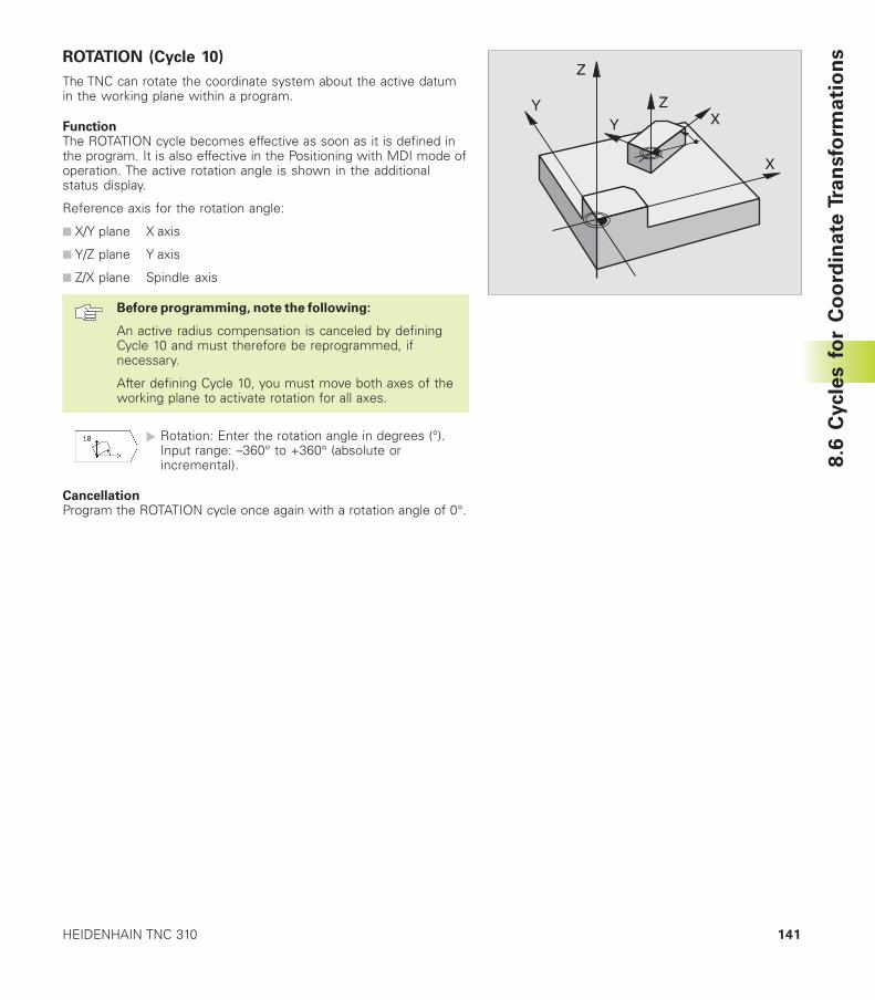
141HEIDENHAIN TNC 310
ROTATION (Cycle 10)
The TNC can rotate the coordinate system about the active datumin the working plane within a program.
FunctionThe ROTATION cycle becomes effective as soon as it is defined inthe program. It is also effective in the Positioning with MDI mode ofoperation. The active rotation angle is shown in the additionalstatus display.
Reference axis for the rotation angle:
■ X/Y plane X axis
■ Y/Z plane Y axis
■ Z/X plane Spindle axis
Before programming, note the following:
An active radius compensation is canceled by definingCycle 10 and must therefore be reprogrammed, ifnecessary.
After defining Cycle 10, you must move both axes of theworking plane to activate rotation for all axes.
� Rotation: Enter the rotation angle in degrees (°).Input range: –360° to +360° (absolute orincremental).
CancellationProgram the ROTATION cycle once again with a rotation angle of 0°.
Z
Z
X
XY
Y
8.6
Cycle
s f
or
Co
ord
ina
te T
ran
sfo
rma
tio
ns
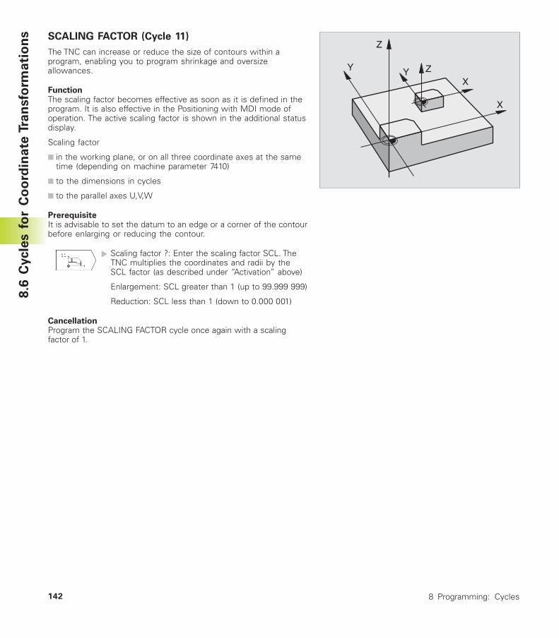
8 Programming: Cycles142
SCALING FACTOR (Cycle 11)
The TNC can increase or reduce the size of contours within aprogram, enabling you to program shrinkage and oversizeallowances.
FunctionThe scaling factor becomes effective as soon as it is defined in theprogram. It is also effective in the Positioning with MDI mode ofoperation. The active scaling factor is shown in the additional statusdisplay.
Scaling factor
■ in the working plane, or on all three coordinate axes at the sametime (depending on machine parameter 7410)
■ to the dimensions in cycles
■ to the parallel axes U,V,W
PrerequisiteIt is advisable to set the datum to an edge or a corner of the contourbefore enlarging or reducing the contour.
� Scaling factor ?: Enter the scaling factor SCL. TheTNC multiplies the coordinates and radii by theSCL factor (as described under “Activation” above)
Enlargement: SCL greater than 1 (up to 99.999 999)
Reduction: SCL less than 1 (down to 0.000 001)
CancellationProgram the SCALING FACTOR cycle once again with a scalingfactor of 1.
8.6
Cycle
s f
or
Co
ord
ina
te T
ran
sfo
rma
tio
ns
Z
Z
X
X
Y Y
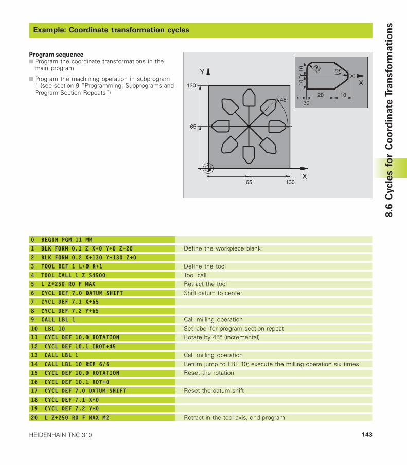
143HEIDENHAIN TNC 310
Example: Coordinate transformation cycles
Program sequence■ Program the coordinate transformations in the
main program
■ Program the machining operation in subprogram1 (see section 9 “Programming: Subprograms andProgram Section Repeats”)
8.6
Cycle
s f
or
Co
ord
ina
te T
ran
sfo
rma
tio
ns
X
Y
65
65
130
130
45°
X
20
30
10
R5 R51010
Define the workpiece blank
Define the toolTool callRetract the toolShift datum to center
Call milling operationSet label for program section repeatRotate by 45° (incremental)
Call milling operationReturn jump to LBL 10; execute the milling operation six timesReset the rotation
Reset the datum shift
Retract in the tool axis, end program
0 BEGIN PGM 11 MM1 BLK FORM 0.1 Z X+0 Y+0 Z-202 BLK FORM 0.2 X+130 Y+130 Z+03 TOOL DEF 1 L+0 R+14 TOOL CALL 1 Z S45005 L Z+250 R0 F MAX6 CYCL DEF 7.0 DATUM SHIFT7 CYCL DEF 7.1 X+658 CYCL DEF 7.2 Y+659 CALL LBL 110 LBL 1011 CYCL DEF 10.0 ROTATION12 CYCL DEF 10.1 IROT+4513 CALL LBL 114 CALL LBL 10 REP 6/615 CYCL DEF 10.0 ROTATION16 CYCL DEF 10.1 ROT+017 CYCL DEF 7.0 DATUM SHIFT18 CYCL DEF 7.1 X+019 CYCL DEF 7.2 Y+020 L Z+250 R0 F MAX M2
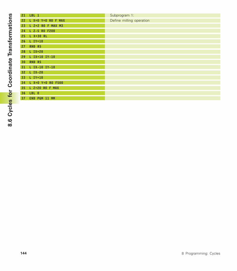
8 Programming: Cycles144
8.6
Cycle
s f
or
Co
ord
ina
te T
ran
sfo
rma
tio
ns 21 LBL 1
22 L X+0 Y+0 R0 F MAX23 L Z+2 R0 F MAX M324 L Z-5 R0 F20025 L X+30 RL26 L IY+1027 RND R528 L IX+2029 L IX+10 IY-1030 RND R531 L IX-10 IY-1032 L IX-2033 L IY+1034 L X+0 Y+0 R0 F50035 L Z+20 R0 F MAX36 LBL 037 END PGM 11 MM
Subprogram 1:Define milling operation
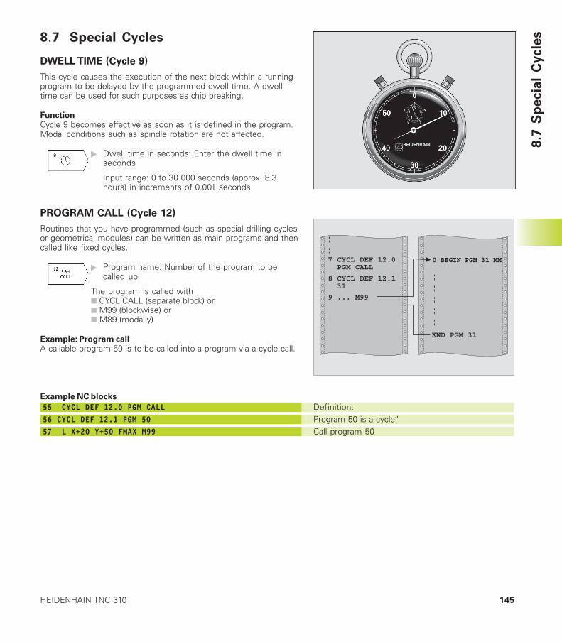
145HEIDENHAIN TNC 310
Definition:Program 50 is a cycle”Call program 50
8.7 Special Cycles
DWELL TIME (Cycle 9)
This cycle causes the execution of the next block within a runningprogram to be delayed by the programmed dwell time. A dwelltime can be used for such purposes as chip breaking.
FunctionCycle 9 becomes effective as soon as it is defined in the program.Modal conditions such as spindle rotation are not affected.
� Dwell time in seconds: Enter the dwell time inseconds
Input range: 0 to 30 000 seconds (approx. 8.3hours) in increments of 0.001 seconds
PROGRAM CALL (Cycle 12)
Routines that you have programmed (such as special drilling cyclesor geometrical modules) can be written as main programs and thencalled like fixed cycles.
� Program name: Number of the program to becalled up
The program is called with■ CYCL CALL (separate block) or■ M99 (blockwise) or■ M89 (modally)
Example: Program callA callable program 50 is to be called into a program via a cycle call.
Example NC blocks
55 CYCL DEF 12.0 PGM CALL56 CYCL DEF 12.1 PGM 5057 L X+20 Y+50 FMAX M99
8.7
Sp
ecia
l C
ycle
s
0 BEGIN PGM 31 MM7 CYCL DEF 12.0 PGM CALL
8 CYCL DEF 12.1 31
9 ... M99
END PGM 31
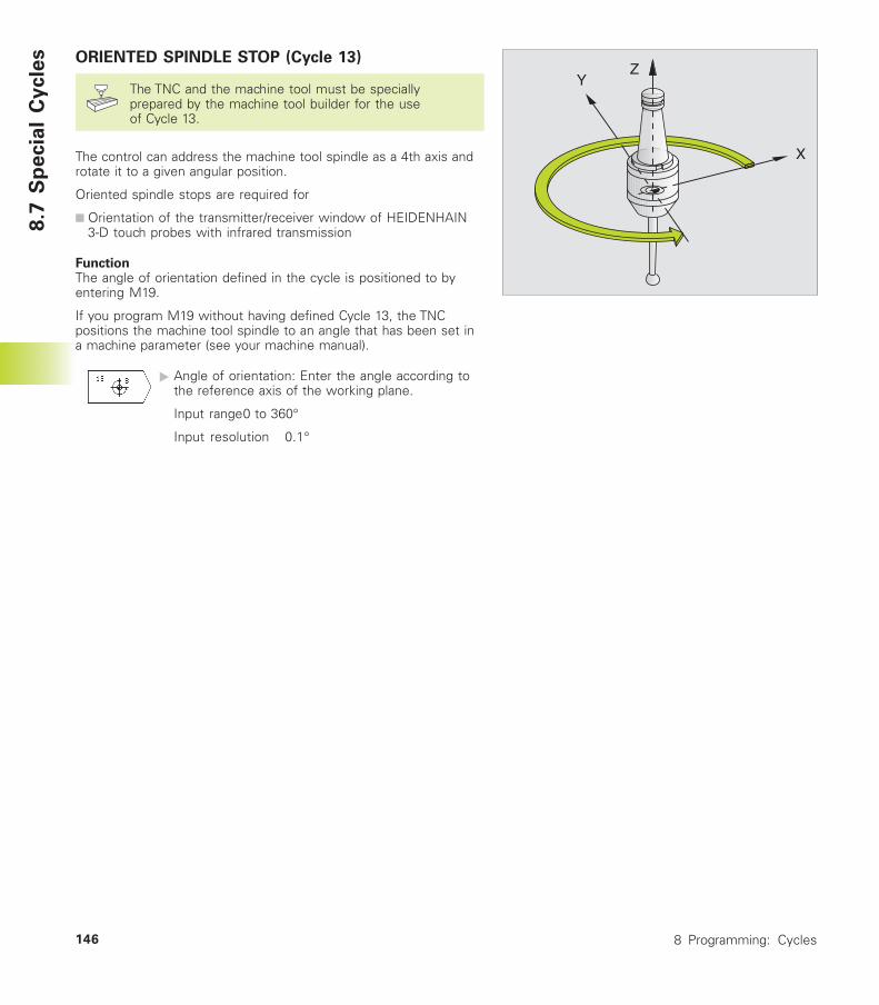
8 Programming: Cycles146
X
YZ
8.7
Sp
ecia
l C
ycle
s ORIENTED SPINDLE STOP (Cycle 13)
The TNC and the machine tool must be speciallyprepared by the machine tool builder for the useof Cycle 13.
The control can address the machine tool spindle as a 4th axis androtate it to a given angular position.
Oriented spindle stops are required for
■ Orientation of the transmitter/receiver window of HEIDENHAIN3-D touch probes with infrared transmission
FunctionThe angle of orientation defined in the cycle is positioned to byentering M19.
If you program M19 without having defined Cycle 13, the TNCpositions the machine tool spindle to an angle that has been set ina machine parameter (see your machine manual).
� Angle of orientation: Enter the angle according tothe reference axis of the working plane.
Input range0 to 360°
Input resolution 0.1°
Programming:
Subprograms andProgram Section Repeats
9
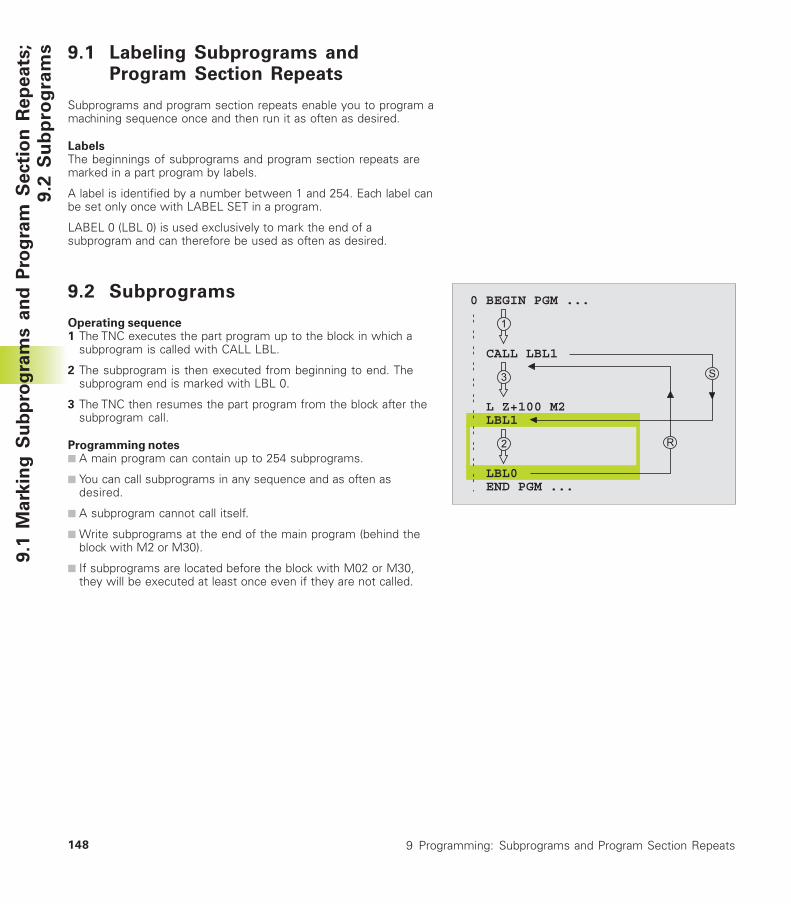
9 Programming: Subprograms and Program Section Repeats148
9.1
Mark
ing
Su
bp
rog
ram
s a
nd
Pro
gra
m S
ecti
on
Rep
eats
;9
.2 S
ub
pro
gra
ms 9.1 Labeling Subprograms and
Program Section Repeats
Subprograms and program section repeats enable you to program amachining sequence once and then run it as often as desired.
LabelsThe beginnings of subprograms and program section repeats aremarked in a part program by labels.
A label is identified by a number between 1 and 254. Each label canbe set only once with LABEL SET in a program.
LABEL 0 (LBL 0) is used exclusively to mark the end of asubprogram and can therefore be used as often as desired.
9.2 Subprograms
Operating sequence1 The TNC executes the part program up to the block in which a
subprogram is called with CALL LBL.
2 The subprogram is then executed from beginning to end. Thesubprogram end is marked with LBL 0.
3 The TNC then resumes the part program from the block after thesubprogram call.
Programming notes■ A main program can contain up to 254 subprograms.
■ You can call subprograms in any sequence and as often asdesired.
■ A subprogram cannot call itself.
■ Write subprograms at the end of the main program (behind theblock with M2 or M30).
■ If subprograms are located before the block with M02 or M30,they will be executed at least once even if they are not called.
0 BEGIN PGM ...
CALL LBL1
L Z+100 M2 LBL1
LBL0 END PGM ...
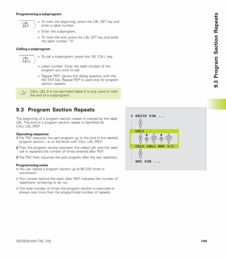
149HEIDENHAIN TNC 310
9.3
Pro
gra
m S
ecti
on
Rep
eatsProgramming a subprogram
� To mark the beginning, press the LBL SET key andenter a label number.
� Enter the subprogram.
� To mark the end, press the LBL SET key and enterthe label number “0”.
Calling a subprogram
� To call a subprogram, press the LBL CALL key.
� Label number: Enter the label number of theprogram you wish to call.
� Repeat REP: Ignore the dialog question with theNO ENT key. Repeat REP is used only for programsection repeats.
CALL LBL 0 is not permitted (label 0 is only used to markthe end of a subprogram).
9.3 Program Section Repeats
The beginning of a program section repeat is marked by the labelLBL. The end of a program section repeat is identified byCALL LBL /REP.
Operating sequence1 The TNC executes the part program up to the end of the labeled
program section, i.e. to the block with CALL LBL /REP.
2 Then the program section between the called LBL and the labelcall is repeated the number of times entered after REP.
3 The TNC then resumes the part program after the last repetition.
Programming notes■ You can repeat a program section up to 65 534 times in
succession.
■ The number behind the slash after REP indicates the number ofrepetitions remaining to be run.
■ The total number of times the program section is executed isalways one more than the programmed number of repeats.
0 BEGIN PGM ...
LBL1
CALL LBL1 REP 2/2
END PGM ...
9 Programming: Subprograms and Program Section Repeats150
9.3
Pro
gra
m S
ecti
on
Rep
eats Programming a program section repeat
� To mark the beginning, press the LBL SET key andenter a label number for the program section youwish to repeat.
� Enter the program section.
Calling a program section repeat
� Press the LBL CALL key and enter the labelnumber of the program section you want to repeatas well as the number of repeats (with RepeatREP).
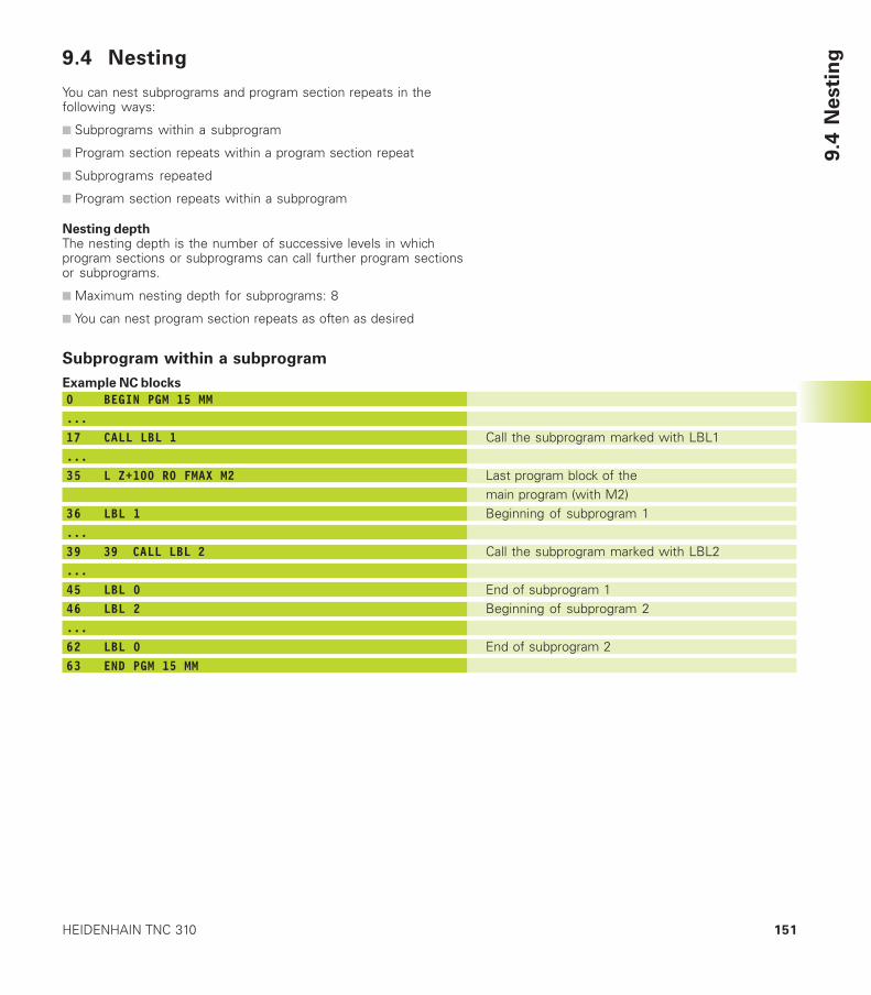
151HEIDENHAIN TNC 310
9.4
Nesti
ng9.4 Nesting
You can nest subprograms and program section repeats in thefollowing ways:
■ Subprograms within a subprogram
■ Program section repeats within a program section repeat
■ Subprograms repeated
■ Program section repeats within a subprogram
Nesting depthThe nesting depth is the number of successive levels in whichprogram sections or subprograms can call further program sectionsor subprograms.
■ Maximum nesting depth for subprograms: 8
■ You can nest program section repeats as often as desired
Subprogram within a subprogram
Example NC blocks
0 BEGIN PGM 15 MM...17 CALL LBL 1...35 L Z+100 R0 FMAX M2
36 LBL 1...39 39 CALL LBL 2...45 LBL 046 LBL 2...62 LBL 063 END PGM 15 MM
Call the subprogram marked with LBL1
Last program block of themain program (with M2)Beginning of subprogram 1
Call the subprogram marked with LBL2
End of subprogram 1Beginning of subprogram 2
End of subprogram 2
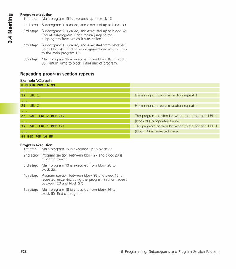
9 Programming: Subprograms and Program Section Repeats152
9.4
Nesti
ng Program execution
1st step: Main program 15 is executed up to block 17.
2nd step: Subprogram 1 is called, and executed up to block 39.
3rd step: Subprogram 2 is called, and executed up to block 62.End of subprogram 2 and return jump to thesubprogram from which it was called.
4th step: Subprogram 1 is called, and executed from block 40up to block 45. End of subprogram 1 and return jumpto the main program 15.
5th step: Main program 15 is executed from block 18 to block35. Return jump to block 1 and end of program.
Repeating program section repeats
Example NC blocks
0 BEGIN PGM 16 MM...15 LBL 1...20 LBL 2...27 CALL LBL 2 REP 2/2...35 CALL LBL 1 REP 1/1...50 END PGM 16 MM
Program execution1st step: Main program 16 is executed up to block 27.
2nd step: Program section between block 27 and block 20 isrepeated twice.
3rd step: Main program 16 is executed from block 28 toblock 35.
4th step: Program section between block 35 and block 15 isrepeated once (including the program section repeatbetween 20 and block 27).
5th step: Main program 16 is executed from block 36 toblock 50. End of program.
Beginning of program section repeat 1
Beginning of program section repeat 2
The program section between this block and LBL 2(block 20) is repeated twice.The program section between this block and LBL 1(block 15) is repeated once.
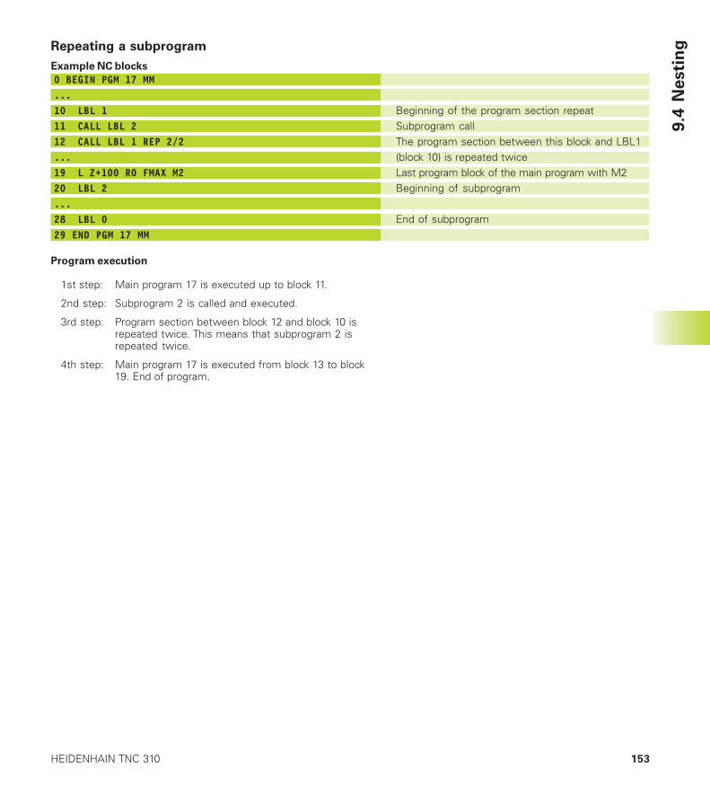
153HEIDENHAIN TNC 310
9.4
Nesti
ngRepeating a subprogram
Example NC blocks
0 BEGIN PGM 17 MM...10 LBL 111 CALL LBL 212 CALL LBL 1 REP 2/2...19 L Z+100 R0 FMAX M220 LBL 2...28 LBL 029 END PGM 17 MM
Program execution
1st step: Main program 17 is executed up to block 11.
2nd step: Subprogram 2 is called and executed.
3rd step: Program section between block 12 and block 10 isrepeated twice. This means that subprogram 2 isrepeated twice.
4th step: Main program 17 is executed from block 13 to block19. End of program.
Beginning of the program section repeatSubprogram callThe program section between this block and LBL1(block 10) is repeated twiceLast program block of the main program with M2Beginning of subprogram
End of subprogram
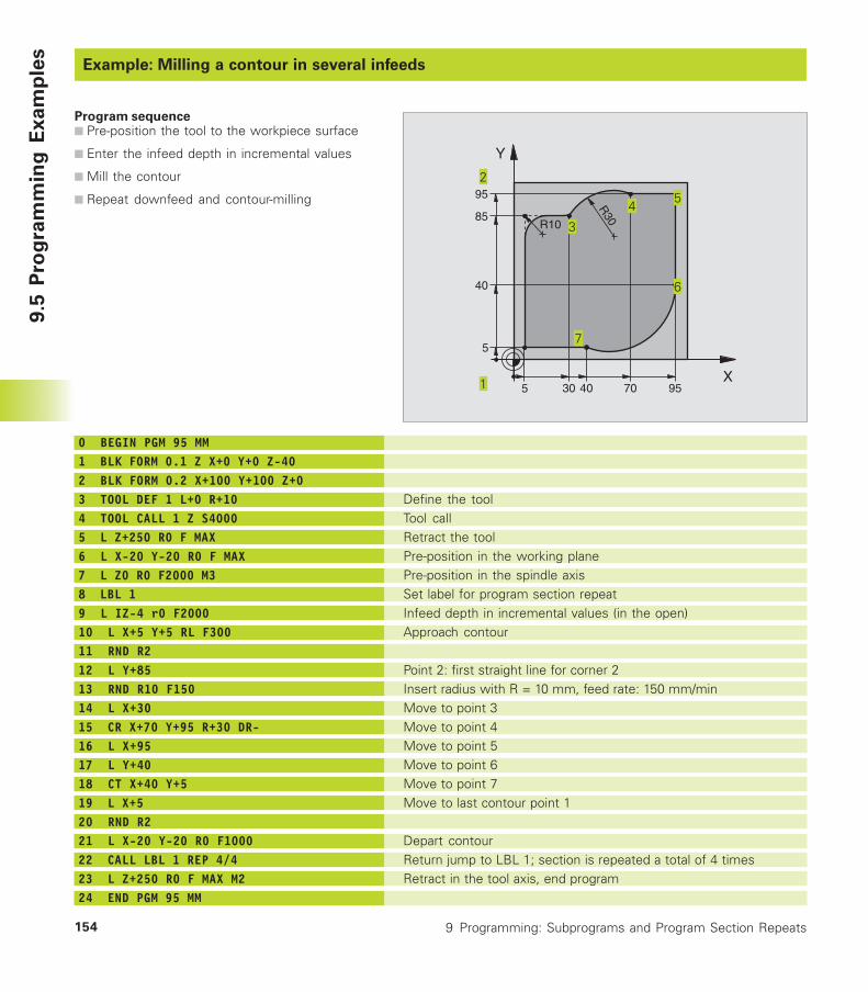
9 Programming: Subprograms and Program Section Repeats154
9.5
Pro
gra
mm
ing
Ex
am
ple
s
Example: Milling a contour in several infeeds
Program sequence■ Pre-position the tool to the workpiece surface
■ Enter the infeed depth in incremental values
■ Mill the contour
■ Repeat downfeed and contour-milling
0 BEGIN PGM 95 MM1 BLK FORM 0.1 Z X+0 Y+0 Z-402 BLK FORM 0.2 X+100 Y+100 Z+03 TOOL DEF 1 L+0 R+104 TOOL CALL 1 Z S40005 L Z+250 R0 F MAX6 L X-20 Y-20 R0 F MAX7 L Z0 R0 F2000 M38 LBL 19 L IZ-4 r0 F200010 L X+5 Y+5 RL F30011 RND R212 L Y+8513 RND R10 F15014 L X+3015 CR X+70 Y+95 R+30 DR-16 L X+9517 L Y+4018 CT X+40 Y+519 L X+520 RND R221 L X-20 Y-20 R0 F100022 CALL LBL 1 REP 4/423 L Z+250 R0 F MAX M224 END PGM 95 MM
Define the toolTool callRetract the toolPre-position in the working planePre-position in the spindle axisSet label for program section repeatInfeed depth in incremental values (in the open)Approach contour
Point 2: first straight line for corner 2Insert radius with R = 10 mm, feed rate: 150 mm/minMove to point 3Move to point 4Move to point 5Move to point 6Move to point 7Move to last contour point 1
Depart contourReturn jump to LBL 1; section is repeated a total of 4 timesRetract in the tool axis, end program
X
Y
955
95
5
85
40
4030 70
R10
R30
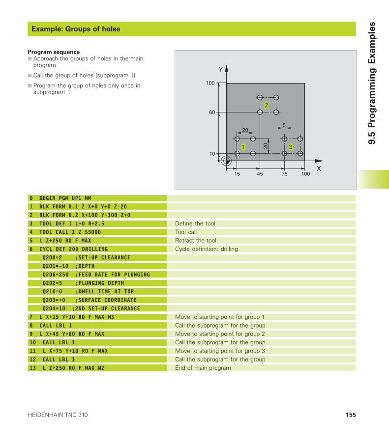
155HEIDENHAIN TNC 310
9.5
Pro
gra
mm
ing
Ex
am
ple
s
Example: Groups of holes
Program sequence■ Approach the groups of holes in the main
program
■ Call the group of holes (subprogram 1)
■ Program the group of holes only once insubprogram 1
0 BEGIN PGM UP1 MM1 BLK FORM 0.1 Z X+0 Y+0 Z-202 BLK FORM 0.2 X+100 Y+100 Z+03 TOOL DEF 1 L+0 R+2.54 TOOL CALL 1 Z S50005 L Z+250 R0 F MAX6 CYCL DEF 200 DRILLING Q200=2 ;SET-UP CLEARANCE Q201=-10 ;DEPTH Q206=250 ;FEED RATE FOR PLUNGING Q202=5 ;PLUNGING DEPTH Q210=0 ;DWELL TIME AT TOP Q203=+0 ;SURFACE COORDINATE Q204=10 ;2ND SET-UP CLEARANCE7 L X+15 Y+10 R0 F MAX M38 CALL LBL 19 L X+45 Y+60 R0 F MAX10 CALL LBL 111 L X+75 Y+10 R0 F MAX12 CALL LBL 113 L Z+250 R0 F MAX M2
Define the toolTool callRetract the toolCycle definition: drilling
Move to starting point for group 1Call the subprogram for the groupMove to starting point for group 2Call the subprogram for the groupMove to starting point for group 3Call the subprogram for the groupEnd of main program
X
Y
15
60
100
100
75
10
45
20
20
5
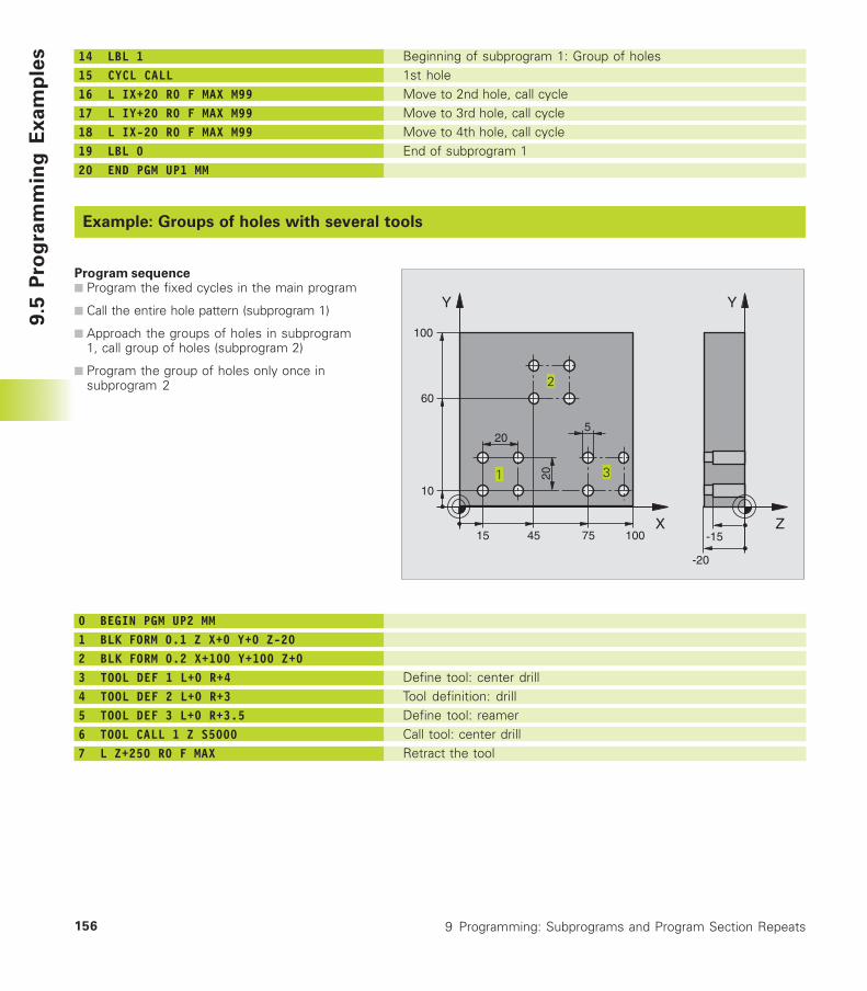
9 Programming: Subprograms and Program Section Repeats156
9.5
Pro
gra
mm
ing
Ex
am
ple
s
Example: Groups of holes with several tools
Program sequence■ Program the fixed cycles in the main program
■ Call the entire hole pattern (subprogram 1)
■ Approach the groups of holes in subprogram1, call group of holes (subprogram 2)
■ Program the group of holes only once insubprogram 2
14 LBL 115 CYCL CALL16 L IX+20 R0 F MAX M9917 L IY+20 R0 F MAX M9918 L IX-20 R0 F MAX M9919 LBL 020 END PGM UP1 MM
Beginning of subprogram 1: Group of holes1st holeMove to 2nd hole, call cycleMove to 3rd hole, call cycleMove to 4th hole, call cycleEnd of subprogram 1
0 BEGIN PGM UP2 MM1 BLK FORM 0.1 Z X+0 Y+0 Z-202 BLK FORM 0.2 X+100 Y+100 Z+03 TOOL DEF 1 L+0 R+44 TOOL DEF 2 L+0 R+35 TOOL DEF 3 L+0 R+3.56 TOOL CALL 1 Z S50007 L Z+250 R0 F MAX
Define tool: center drillTool definition: drillDefine tool: reamerCall tool: center drillRetract the tool
X
Y
15
60
100
100
75
10
45
20
20
5
Z
Y
-20
-15
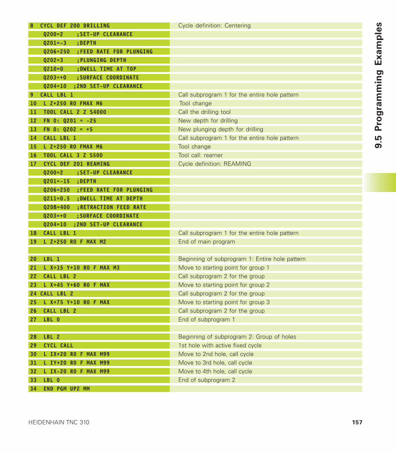
157HEIDENHAIN TNC 310
9.5
Pro
gra
mm
ing
Ex
am
ple
s8 CYCL DEF 200 DRILLING Q200=2 ;SET-UP CLEARANCE Q201=-3 ;DEPTH Q206=250 ;FEED RATE FOR PLUNGING Q202=3 ;PLUNGING DEPTH Q210=0 ;DWELL TIME AT TOP Q203=+0 ;SURFACE COORDINATE Q204=10 ;2ND SET-UP CLEARANCE9 CALL LBL 110 L Z+250 R0 FMAX M611 TOOL CALL 2 Z S400012 FN 0: Q201 = -2513 FN 0: Q202 = +514 CALL LBL 115 L Z+250 R0 FMAX M616 TOOL CALL 3 Z S50017 CYCL DEF 201 REAMING Q200=2 ;SET-UP CLEARANCE Q201=-15 ;DEPTH Q206=250 ;FEED RATE FOR PLUNGING Q211=0.5 ;DWELL TIME AT DEPTH Q208=400 ;RETRACTION FEED RATE Q203=+0 ;SURFACE COORDINATE Q204=10 ;2ND SET-UP CLEARANCE18 CALL LBL 119 L Z+250 R0 F MAX M2
20 LBL 121 L X+15 Y+10 R0 F MAX M322 CALL LBL 223 L X+45 Y+60 R0 F MAX24 CALL LBL 225 L X+75 Y+10 R0 F MAX26 CALL LBL 227 LBL 0
28 LBL 229 CYCL CALL30 L IX+20 R0 F MAX M9931 L IY+20 R0 F MAX M9932 L IX-20 R0 F MAX M9933 LBL 034 END PGM UP2 MM
Cycle definition: Centering
Call subprogram 1 for the entire hole patternTool changeCall the drilling toolNew depth for drillingNew plunging depth for drillingCall subprogram 1 for the entire hole patternTool changeTool call: reamerCycle definition: REAMING
Call subprogram 1 for the entire hole patternEnd of main program
Beginning of subprogram 1: Entire hole patternMove to starting point for group 1Call subprogram 2 for the groupMove to starting point for group 2Call subprogram 2 for the groupMove to starting point for group 3Call subprogram 2 for the groupEnd of subprogram 1
Beginning of subprogram 2: Group of holes1st hole with active fixed cycleMove to 2nd hole, call cycleMove to 3rd hole, call cycleMove to 4th hole, call cycleEnd of subprogram 2

Programming:
Q Parameters
10
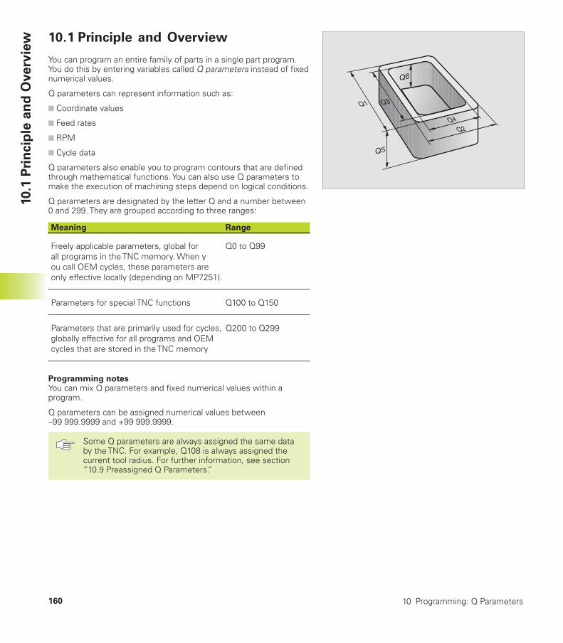
10 Programming: Q Parameters160
10.1
Pri
ncip
le a
nd
Overv
iew 10.1 Principle and Overview
You can program an entire family of parts in a single part program.You do this by entering variables called Q parameters instead of fixednumerical values.
Q parameters can represent information such as:
■ Coordinate values
■ Feed rates
■ RPM
■ Cycle data
Q parameters also enable you to program contours that are definedthrough mathematical functions. You can also use Q parameters tomake the execution of machining steps depend on logical conditions.
Q parameters are designated by the letter Q and a number between0 and 299. They are grouped according to three ranges:
Meaning Range
Freely applicable parameters, global for Q0 to Q99all programs in the TNC memory. When you call OEM cycles, these parameters areonly effective locally (depending on MP7251).
Parameters for special TNC functions Q100 to Q150
Parameters that are primarily used for cycles, Q200 to Q299globally effective for all programs and OEMcycles that are stored in the TNC memory
Programming notesYou can mix Q parameters and fixed numerical values within aprogram.
Q parameters can be assigned numerical values between–99 999.9999 and +99 999.9999.
Some Q parameters are always assigned the same databy the TNC. For example, Q108 is always assigned thecurrent tool radius. For further information, see section“10.9 Preassigned Q Parameters.”
Q4Q2
Q3Q1
Q5
Q6
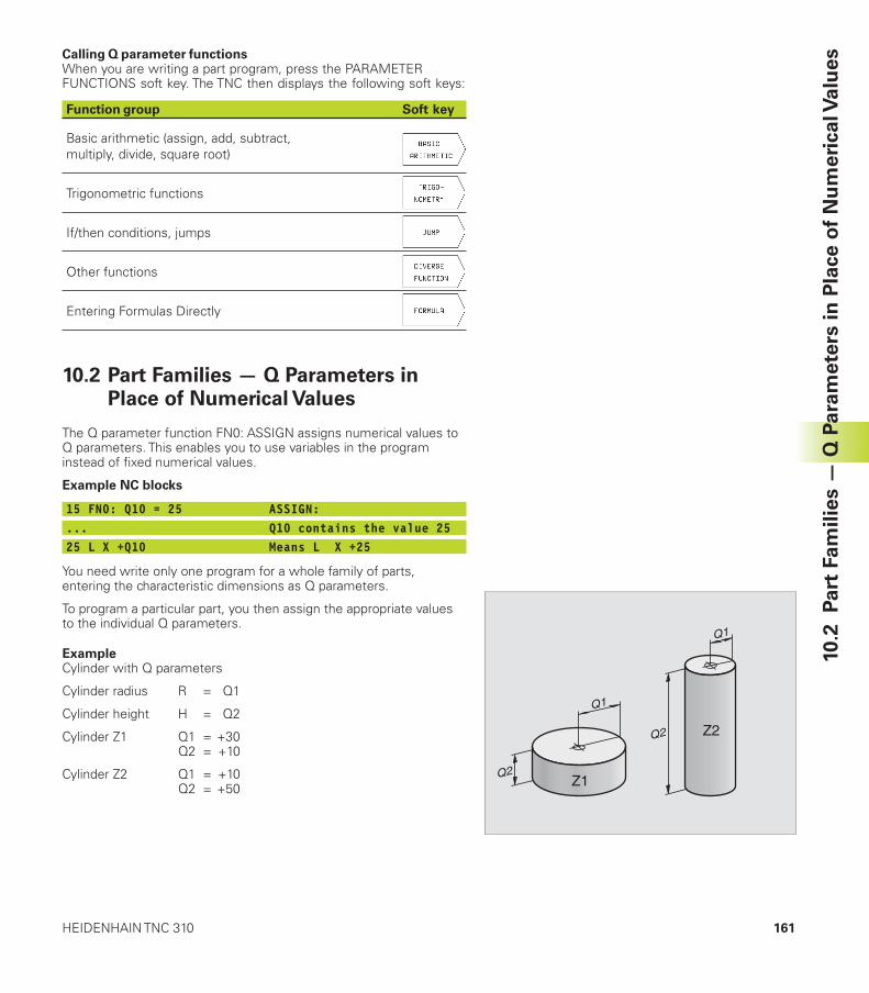
161HEIDENHAIN TNC 310
10.2
P
art
Fam
ilie
s —
Q P
ara
mete
rs in
Pla
ce o
f N
um
eri
cal V
alu
esCalling Q parameter functions
When you are writing a part program, press the PARAMETERFUNCTIONS soft key. The TNC then displays the following soft keys:
Function group Soft key
Basic arithmetic (assign, add, subtract,multiply, divide, square root)
Trigonometric functions
If/then conditions, jumps
Other functions
Entering Formulas Directly
10.2 Part Families — Q Parameters inPlace of Numerical Values
The Q parameter function FN0: ASSIGN assigns numerical values toQ parameters. This enables you to use variables in the programinstead of fixed numerical values.
Example NC blocks
15 FN0: Q10 = 25 ASSIGN:... Q10 contains the value 2525 L X +Q10 Means L X +25
You need write only one program for a whole family of parts,entering the characteristic dimensions as Q parameters.
To program a particular part, you then assign the appropriate valuesto the individual Q parameters.
ExampleCylinder with Q parameters
Cylinder radius R = Q1
Cylinder height H = Q2
Cylinder Z1 Q1 = +30Q2 = +10
Cylinder Z2 Q1 = +10Q2 = +50 Z1
Q1
Q2
Z2
Q1
Q2
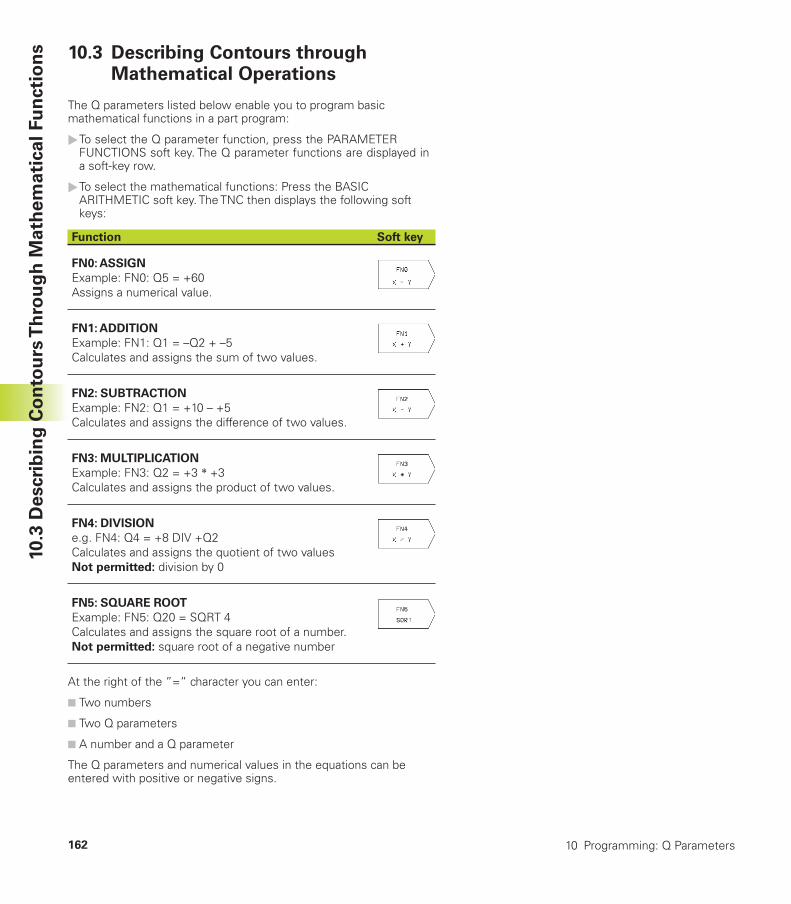
10 Programming: Q Parameters162
10.3
Descri
bin
g C
on
tou
rs T
hro
ug
h M
ath
em
ati
cal
Fu
ncti
on
s 10.3 Describing Contours throughMathematical Operations
The Q parameters listed below enable you to program basicmathematical functions in a part program:
�To select the Q parameter function, press the PARAMETERFUNCTIONS soft key. The Q parameter functions are displayed ina soft-key row.
�To select the mathematical functions: Press the BASICARITHMETIC soft key. The TNC then displays the following softkeys:
Function Soft key
FN0: ASSIGN
Example: FN0: Q5 = +60Assigns a numerical value.
FN1: ADDITION
Example: FN1: Q1 = –Q2 + –5Calculates and assigns the sum of two values.
FN2: SUBTRACTION
Example: FN2: Q1 = +10 – +5Calculates and assigns the difference of two values.
FN3: MULTIPLICATION
Example: FN3: Q2 = +3 ��+3Calculates and assigns the product of two values.
FN4: DIVISION
e.g. FN4: Q4 = +8 DIV +Q2Calculates and assigns the quotient of two valuesNot permitted: division by 0
FN5: SQUARE ROOT
Example: FN5: Q20 = SQRT 4Calculates and assigns the square root of a number.Not permitted: square root of a negative number
At the right of the ”=” character you can enter:
■ Two numbers
■ Two Q parameters
■ A number and a Q parameter
The Q parameters and numerical values in the equations can beentered with positive or negative signs.
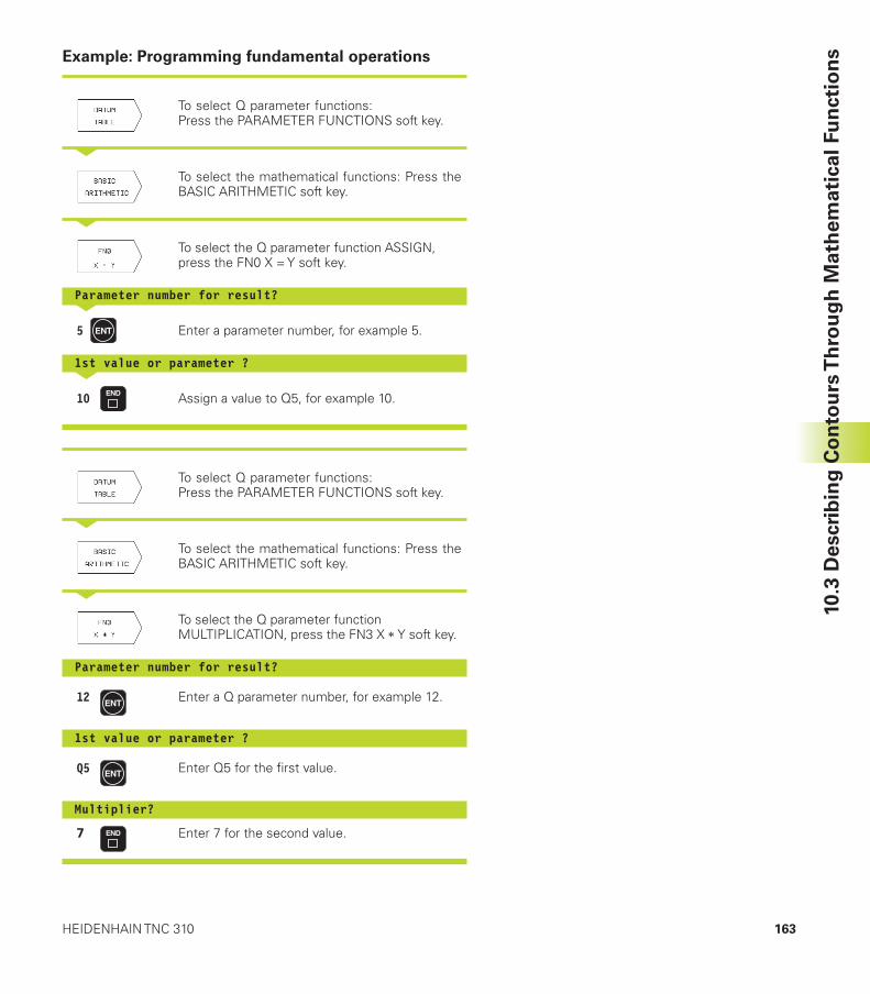
163HEIDENHAIN TNC 310
10.3
Descri
bin
g C
on
tou
rs T
hro
ug
h M
ath
em
ati
cal
Fu
ncti
on
sExample: Programming fundamental operations
To select Q parameter functions:Press the PARAMETER FUNCTIONS soft key.
<
To select the mathematical functions: Press theBASIC ARITHMETIC soft key.
<
To select the Q parameter function ASSIGN,press the FN0 X = Y soft key.
Parameter number for result?<
5 Enter a parameter number, for example 5.
1st value or parameter ?<
10 Assign a value to Q5, for example 10.
To select Q parameter functions:Press the PARAMETER FUNCTIONS soft key.
<
To select the mathematical functions: Press theBASIC ARITHMETIC soft key.
<
To select the Q parameter functionMULTIPLICATION, press the FN3 X ��Y soft key.
Parameter number for result?
12 Enter a Q parameter number, for example 12.
1st value or parameter ?
Q5 Enter Q5 for the first value.
Multiplier?
7 Enter 7 for the second value.
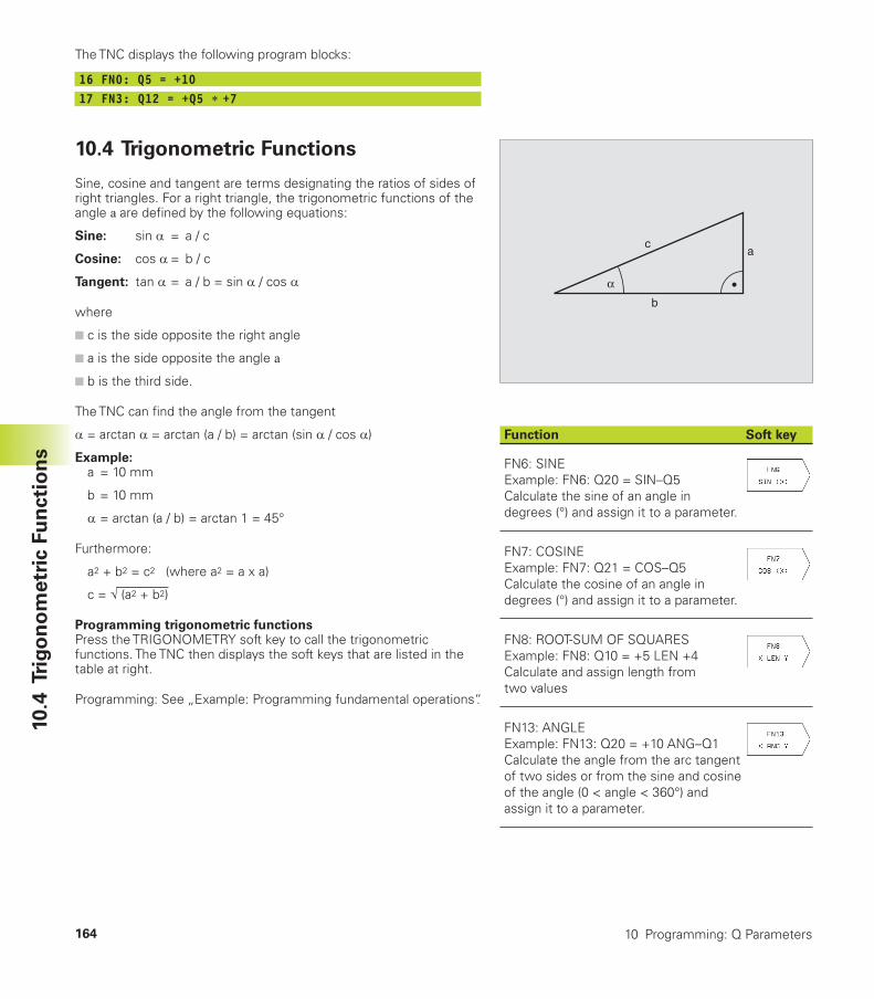
10 Programming: Q Parameters164
10.4
Tri
go
no
metr
ic F
un
cti
on
s
b
ca
α
Function Soft key
FN6: SINEExample: FN6: Q20 = SIN–Q5Calculate the sine of an angle indegrees (°) and assign it to a parameter.
FN7: COSINEExample: FN7: Q21 = COS–Q5Calculate the cosine of an angle indegrees (°) and assign it to a parameter.
FN8: ROOT-SUM OF SQUARESExample: FN8: Q10 = +5 LEN +4Calculate and assign length fromtwo values
FN13: ANGLEExample: FN13: Q20 = +10 ANG–Q1Calculate the angle from the arc tangentof two sides or from the sine and cosineof the angle (0 < angle < 360°) andassign it to a parameter.
The TNC displays the following program blocks:
16 FN0: Q5 = +1017 FN3: Q12 = +Q5 ��+7
10.4 Trigonometric Functions
Sine, cosine and tangent are terms designating the ratios of sides ofright triangles. For a right triangle, the trigonometric functions of theangle � are defined by the following equations:
Sine: sin � = a / c
Cosine: cos � = b / c
Tangent: tan � = a / b = sin � / cos �
where
■ c is the side opposite the right angle
■ a is the side opposite the angle �
■ b is the third side.
The TNC can find the angle from the tangent
� = arctan � = arctan (a / b) = arctan (sin � / cos �)
Example:a = 10 mm
b = 10 mm
� = arctan (a / b) = arctan 1 = 45°
Furthermore:
a2 + b2 = c2 (where a2 = a x a)
c = � (a2 + b2)
Programming trigonometric functionsPress the TRIGONOMETRY soft key to call the trigonometricfunctions. The TNC then displays the soft keys that are listed in thetable at right.
Programming: See „Example: Programming fundamental operations“.
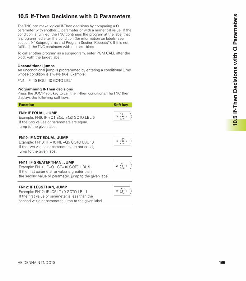
165HEIDENHAIN TNC 310
10.5
If-
Th
en
Decis
ion
s w
ith
Q P
ara
mete
rs10.5 If-Then Decisions with Q Parameters
The TNC can make logical If-Then decisions by comparing a Qparameter with another Q parameter or with a numerical value. If thecondition is fulfilled, the TNC continues the program at the label thatis programmed after the condition (for information on labels, seesection 9 “Subprograms and Program Section Repeats”). If it is notfulfilled, the TNC continues with the next block.
To call another program as a subprogram, enter PGM CALL after theblock with the target label.
Unconditional jumpsAn unconditional jump is programmed by entering a conditional jumpwhose condition is always true. Example:
FN9: IF+10 EQU+10 GOTO LBL1
Programming If-Then decisionsPress the JUMP soft key to call the if-then conditions. The TNC thendisplays the following soft keys:
Function Soft key
FN9: IF EQUAL, JUMP
Example: FN9: IF +Q1 EQU +Q3 GOTO LBL 5If the two values or parameters are equal,jump to the given label.
FN10: IF NOT EQUAL, JUMP
Example: FN10: IF +10 NE –Q5 GOTO LBL 10If the two values or parameters are not equal,jump to the given label.
FN11: IF GREATER THAN, JUMP
Example: FN11: IF+Q1 GT+10 GOTO LBL 5If the first parameter or value is greater thanthe second value or parameter, jump to the given label.
FN12: IF LESS THAN, JUMP
Example: FN12: IF+Q5 LT+0 GOTO LBL 1If the first value or parameter is less than thesecond value or parameter, jump to the given label.
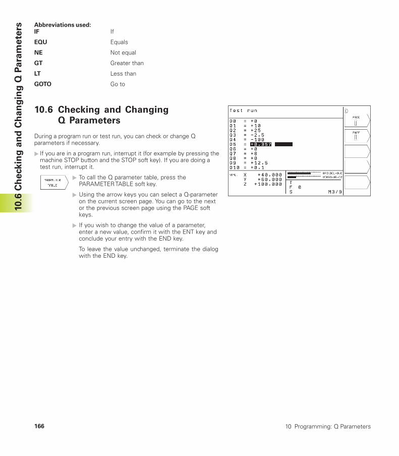
10 Programming: Q Parameters166
10.6
Ch
eckin
g a
nd
Ch
an
gin
g Q
Para
mete
rs Abbreviations used:IF If
EQU Equals
NE Not equal
GT Greater than
LT Less than
GOTO Go to
10.6 Checking and ChangingQ Parameters
During a program run or test run, you can check or change Qparameters if necessary.
� If you are in a program run, interrupt it (for example by pressing themachine STOP button and the STOP soft key). If you are doing atest run, interrupt it.
� To call the Q parameter table, press thePARAMETER TABLE soft key.
� Using the arrow keys you can select a Q-parameteron the current screen page. You can go to the nextor the previous screen page using the PAGE softkeys.
� If you wish to change the value of a parameter,enter a new value, confirm it with the ENT key andconclude your entry with the END key.
To leave the value unchanged, terminate the dialogwith the END key.
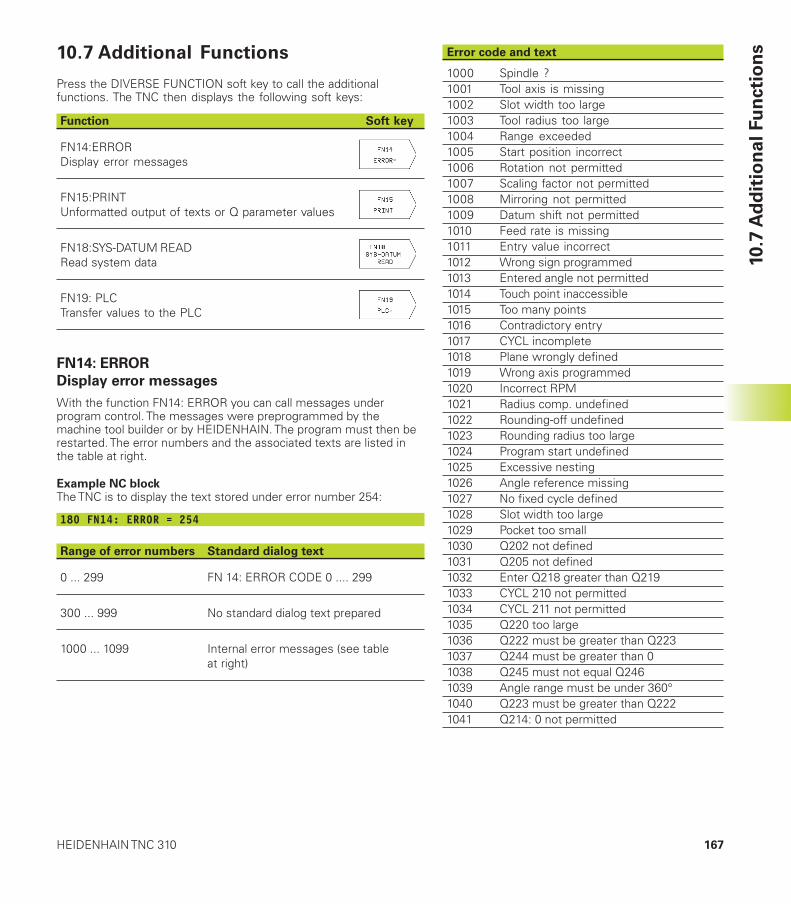
167HEIDENHAIN TNC 310
Error code and text
1000 Spindle ?1001 Tool axis is missing1002 Slot width too large1003 Tool radius too large1004 Range exceeded1005 Start position incorrect1006 Rotation not permitted1007 Scaling factor not permitted1008 Mirroring not permitted1009 Datum shift not permitted1010 Feed rate is missing1011 Entry value incorrect1012 Wrong sign programmed1013 Entered angle not permitted1014 Touch point inaccessible1015 Too many points1016 Contradictory entry1017 CYCL incomplete1018 Plane wrongly defined1019 Wrong axis programmed1020 Incorrect RPM1021 Radius comp. undefined1022 Rounding-off undefined1023 Rounding radius too large1024 Program start undefined1025 Excessive nesting1026 Angle reference missing1027 No fixed cycle defined1028 Slot width too large1029 Pocket too small1030 Q202 not defined1031 Q205 not defined1032 Enter Q218 greater than Q2191033 CYCL 210 not permitted1034 CYCL 211 not permitted1035 Q220 too large1036 Q222 must be greater than Q2231037 Q244 must be greater than 01038 Q245 must not equal Q2461039 Angle range must be under 360°1040 Q223 must be greater than Q2221041 Q214: 0 not permitted
10.7 Additional Functions
Press the DIVERSE FUNCTION soft key to call the additionalfunctions. The TNC then displays the following soft keys:
Function Soft key
FN14:ERRORDisplay error messages
FN15:PRINTUnformatted output of texts or Q parameter values
FN18:SYS-DATUM READRead system data
FN19: PLCTransfer values to the PLC
FN14: ERROR
Display error messages
With the function FN14: ERROR you can call messages underprogram control. The messages were preprogrammed by themachine tool builder or by HEIDENHAIN. The program must then berestarted. The error numbers and the associated texts are listed inthe table at right.
Example NC blockThe TNC is to display the text stored under error number 254:
180 FN14: ERROR = 254
Range of error numbers Standard dialog text
0 ... 299 FN 14: ERROR CODE 0 .... 299
300 ... 999 No standard dialog text prepared
1000 ... 1099 Internal error messages (see tableat right)
10.7
Ad
dit
ion
al
Fu
ncti
on
s
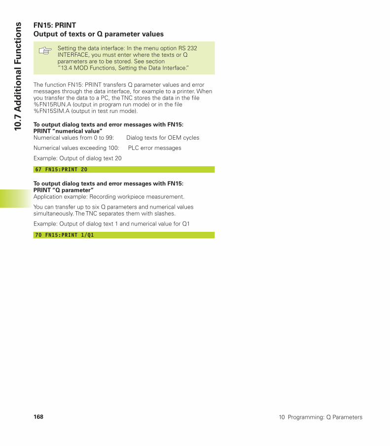
10 Programming: Q Parameters168
FN15: PRINT
Output of texts or Q parameter values
Setting the data interface: In the menu option RS 232INTERFACE, you must enter where the texts or Qparameters are to be stored. See section”13.4 MOD Functions, Setting the Data Interface.”
The function FN15: PRINT transfers Q parameter values and errormessages through the data interface, for example to a printer. Whenyou transfer the data to a PC, the TNC stores the data in the file%FN15RUN.A (output in program run mode) or in the file%FN15SIM.A (output in test run mode).
To output dialog texts and error messages with FN15:PRINT “numerical value”Numerical values from 0 to 99: Dialog texts for OEM cycles
Numerical values exceeding 100: PLC error messages
Example: Output of dialog text 20
67 FN15:PRINT 20
To output dialog texts and error messages with FN15:PRINT “Q parameter”Application example: Recording workpiece measurement.
You can transfer up to six Q parameters and numerical valuessimultaneously. The TNC separates them with slashes.
Example: Output of dialog text 1 and numerical value for Q1
70 FN15:PRINT 1/Q1
10.7
Ad
dit
ion
al
Fu
ncti
on
s
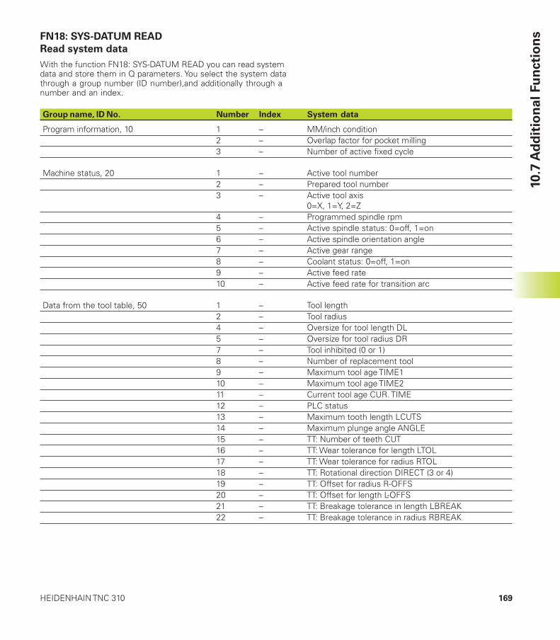
169HEIDENHAIN TNC 310
FN18: SYS-DATUM READ
Read system data
With the function FN18: SYS-DATUM READ you can read systemdata and store them in Q parameters. You select the system datathrough a group number (ID number),and additionally through anumber and an index.
10.7
Ad
dit
ion
al
Fu
ncti
on
s
Group name, ID No. Number Index System data
Program information, 10 1 – MM/inch condition2 – Overlap factor for pocket milling3 – Number of active fixed cycle
Machine status, 20 1 – Active tool number2 – Prepared tool number3 – Active tool axis
0=X, 1=Y, 2=Z4 – Programmed spindle rpm5 – Active spindle status: 0=off, 1=on6 – Active spindle orientation angle7 – Active gear range8 – Coolant status: 0=off, 1=on9 – Active feed rate10 – Active feed rate for transition arc
Data from the tool table, 50 1 – Tool length2 – Tool radius4 – Oversize for tool length DL5 – Oversize for tool radius DR7 – Tool inhibited (0 or 1)8 – Number of replacement tool9 – Maximum tool age TIME110 – Maximum tool age TIME211 – Current tool age CUR. TIME12 – PLC status13 – Maximum tooth length LCUTS14 – Maximum plunge angle ANGLE15 – TT: Number of teeth CUT16 – TT: Wear tolerance for length LTOL17 – TT: Wear tolerance for radius RTOL18 – TT: Rotational direction DIRECT (3 or 4)19 – TT: Offset for radius R-OFFS20 – TT: Offset for length L-OFFS21 – TT: Breakage tolerance in length LBREAK22 – TT: Breakage tolerance in radius RBREAK
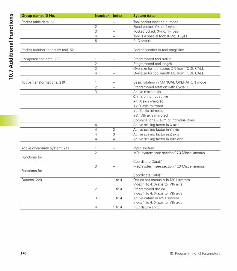
10 Programming: Q Parameters170
10.7
Ad
dit
ion
al
Fu
ncti
on
s Group name, ID No. Number Index System data
Pocket table data, 51 1 – Tool pocket location number2 – Fixed pocket: 0=no, 1=yes3 – Pocket locked: 0=no, 1= yes4 – Tool is a special tool: 0=no, 1=yes5 – PLC status
Pocket number for active tool, 52 1 – Pocket number in tool magazine
Compensation data, 200 1 – Programmed tool radius2 – Programmed tool length3 – Oversize for tool radius DR from TOOL CALL4 – Oversize for tool length DL from TOOL CALL
Active transformations, 210 1 – Basic rotation in MANUAL OPERATION mode2 – Programmed rotation with Cycle 103 – Active mirror axis
0: mirroring not active+1: X axis mirrored+2: Y axis mirrored+4: Z axis mirrored+8: IVth axis mirroredCombinations = sum of individual axes
4 1 Active scaling factor in X axis4 2 Active scaling factor in Y axis4 3 Active scaling factor in Z axis4 4 Active scaling factor in IVth axis
Active coordinate system, 211 1 – Input system2 – M91 system (see section ”7.3 Miscellaneous
Functions forCoordinate Data).”
3 – M92 system (see section ”7.3 MiscellaneousFunctions for
Coordinate Data).”Datums, 220 1 1 to 4 Datum set manually in M91 system
Index 1 to 4: X-axis to IVth axis2 1 to 4 Programmed datum
Index 1 to 4: X-axis to IVth axis3 1 to 4 Active datum in M91 system
Index 1 to 4: X-axis to IVth axis4 1 to 4 PLC datum shift
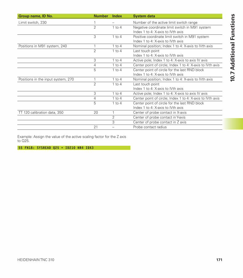
171HEIDENHAIN TNC 310
10.7
Ad
dit
ion
al
Fu
ncti
on
sGroup name, ID No. Number Index System data
Limit switch, 230 1 – Number of the active limit switch range2 1 to 4 Negative coordinate limit switch in M91 system
Index 1 to 4: X-axis to IVth axis3 1 to 4 Positive coordinate limit switch in M91 system
Index 1 to 4: X-axis to IVth axisPositions in M91 system, 240 1 1 to 4 Nominal position; Index 1 to 4: X-axis to IVth axis
2 1 to 4 Last touch pointIndex 1 to 4: X-axis to IVth axis
3 1 to 4 Active pole; Index 1 to 4: X-axis to axis IV axis4 1 to 4 Center point of circle; Index 1 to 4: X-axis to IVth axis5 1 to 4 Center point of circle for the last RND block
Index 1 to 4: X-axis to IVth axisPositions in the input system, 270 1 1 to 4 Nominal position; Index 1 to 4: X-axis to IVth axis
2 1 to 4 Last touch pointIndex 1 to 4: X-axis to IVth axis
3 1 to 4 Active pole; Index 1 to 4: X-axis to axis IV axis4 1 to 4 Center point of circle; Index 1 to 4: X-axis to IVth axis5 1 to 4 Center point of circle for the last RND block
Index 1 to 4: X-axis to IVth axisTT 120 calibration data, 350 20 1 Center of probe contact in X-axis
2 Center of probe contact in Y-axis3 Center of probe contact in Z axis
21 – Probe contact radius
Example: Assign the value of the active scaling factor for the Z axisto Q25.
55 FN18: SYSREAD Q25 = ID210 NR4 IDX3
10 Programming: Q Parameters172
FN19: PLC
Transferring values to the PLC
The function FN19: PLC transfers up to two numerical values or Qparameter contents to the PLC.
Increments and units: 0.1 µm or 0.0001°
Example: Transfer the numerical value 10 (which means 1 µm or0.001°) to the PLC
56 FN19:PLC=+10/+Q3
10.7
Ad
dit
ion
al
Fu
ncti
on
s
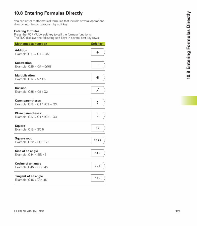
173HEIDENHAIN TNC 310
10.8 Entering Formulas Directly
You can enter mathematical formulas that include several operationsdirectly into the part program by soft key.
Entering formulasPress the FORMULA soft key to call the formula functions.The TNC displays the following soft keys in several soft-key rows:
Mathematical function Soft key
Addition
Example: Q10 = Q1 + Q5
Subtraction
Example: Q25 = Q7 – Q108
Multiplication
Example: Q12 = 5 � Q5
Division
Example: Q25 = Q1 / Q2
Open parentheses
Example: Q12 = Q1 � (Q2 + Q3)
Close parentheses
Example: Q12 = Q1 � (Q2 + Q3)
Square
Example: Q15 = SQ 5
Square root
Example: Q22 = SQRT 25
Sine of an angle
Example: Q44 = SIN 45
Cosine of an angle
Example: Q45 = COS 45
Tangent of an angle
Example: Q46 = TAN 45
10.8
En
teri
ng
Fo
rmu
las D
irectl
y
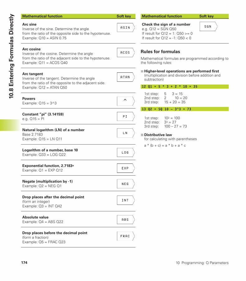
10 Programming: Q Parameters174
Mathematical function Soft key
Arc sine
Inverse of the sine. Determine the anglefrom the ratio of the opposite side to the hypotenuse.Example: Q10 = ASIN 0.75
Arc cosine
Inverse of the cosine. Determine the anglefrom the ratio of the adjacent side to the hypotenuse.Example: Q11 = ACOS Q40
Arc tangent
Inverse of the tangent. Determine the anglefrom the ratio of the opposite to the adjacent side.Example: Q12 = ATAN Q50
Powers
Example: Q15 = 3^3
Constant ”pi” (3.14159)
e.g. Q15 = PI
Natural logarithm (LN) of a number
Base 2.7183Example: Q15 = LN Q11
Logarithm of a number, base 10
Example: Q33 = LOG Q22
Exponential function, 2.7183n
Example: Q1 = EXP Q12
Negate (multiplication by -1)
Example: Q2 = NEG Q1
Drop places after the decimal point
(form an integer)Example: Q3 = INT Q42
Absolute value
Example: Q4 = ABS Q22
Drop places before the decimal point
(form a fraction)Example: Q5 = FRAC Q23
10.8
En
teri
ng
Fo
rmu
las D
irectl
y Mathematical function Soft key
Check the sign of a number
e.g. Q12 = SGN Q50If result for Q12 = 1: Q50 >= 0If result for Q12 = -1: Q50 < 0
Rules for formulas
Mathematical formulas are programmed according tothe following rules:
n Higher-level operations are performed first(multiplication and division before addition andsubtraction)
12 Q1 = 5 * 3 + 2 * 10 = 35
1st step: 5 3 = 152nd step: 2 10 = 203rd step: 15 + 20 = 35
13 Q2 = SQ 10 – 3^3 = 73
1st step: 102 = 1002nd step: 33 = 273rd step: 100 – 27 = 73
n Distributive lawfor calculating with parentheses
a * (b + c) = a * b + a * c
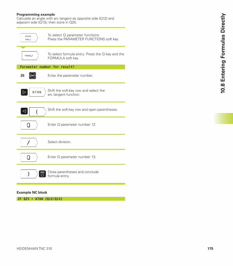
175HEIDENHAIN TNC 310
Programming exampleCalculate an angle with arc tangent as opposite side (Q12) andadjacent side (Q13); then store in Q25.
To select Q parameter functions:Press the PARAMETER FUNCTIONS soft key.
<
To select formula entry: Press the Q key and theFORMULA soft key.
Parameter number for result?
25 Enter the parameter number.
Shift the soft-key row and select thearc tangent function.
Shift the soft-key row and open parentheses.
Enter Q parameter number 12.
Select division.
Enter Q parameter number 13.
Close parentheses and concludeformula entry.
Example NC block
37 Q25 = ATAN (Q12/Q13)
10.8
En
teri
ng
Fo
rmu
las D
irectl
y
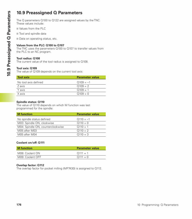
10 Programming: Q Parameters176
10.9
Pre
assig
ned
Q P
ara
mete
rs 10.9 Preassigned Q Parameters
The Q parameters Q100 to Q122 are assigned values by the TNC.These values include:
■ Values from the PLC
■ Tool and spindle data
■ Data on operating status, etc.
Values from the PLC: Q100 to Q107The TNC uses the parameters Q100 to Q107 to transfer values fromthe PLC to an NC program.
Tool radius: Q108The current value of the tool radius is assigned to Q108.
Tool axis: Q109The value of Q109 depends on the current tool axis:
Tool axis Parameter value
No tool axis defined Q109 = –1Z axis Q109 = 2Y axis Q109 = 1X axis Q109 = 0
Spindle status: Q110The value of Q110 depends on which M function was lastprogrammed for the spindle:
M function Parameter value
No spindle status defined Q110 = –1M03: Spindle ON, clockwise Q110 = 0M04: Spindle ON, counterclockwise Q110 = 1M05 after M03 Q110 = 2M05 after M04 Q110 = 3
Coolant on/off: Q111
M function Parameter value
M08: Coolant ON Q111 = 1M09: Coolant OFF Q111 = 0
Overlap factor: Q112The overlap factor for pocket milling (MP7430) is assigned to Q112.

177HEIDENHAIN TNC 310
10.9
Pre
assig
ned
Q P
ara
mete
rsUnit of measurement for dimensions in the program: Q113The value of parameter Q113 specifies whether the highest-level NCprogram (for nesting with PGM CALL) is programmed in millimetersor inches.
Dimensions of the main program Parameter value
Metric system (mm) Q113 = 0Inch system (inches) Q113 = 1
Tool length: Q114The current value for the tool length is assigned to Q114.
Coordinates after probing during program runThe parameters Q115 to Q118 contain the coordinates of the spindleposition at the moment of contact during programmed measurementwith the 3-D touch probe.
The length and radius of the probe tip are not compensated in thesecoordinates.
Coordinate axis Parameter
X axis Q115Y axis Q116Z axis Q117IVth axis Q118
Deviation between actual value and nominal value duringautomatic tool measurement with the TT 120
Actual-nominal deviation Parameter
Tool length Q115Tool radius Q116
Active tool radius compensation
Active radius compensation Parameter value
R0 Q123 = 0RL Q123 = 1RR Q123 = 2R+ Q123 = 3R– Q123 = 4
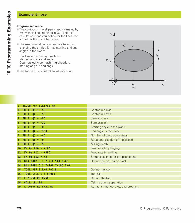
10 Programming: Q Parameters178
Example: Ellipse
10.1
0 P
rog
ram
min
g E
xam
ple
sExample: Ellipse
Center in X axisCenter in Y axisSemiaxis in XSemiaxis in YStarting angle in the planeEnd angle in the planeNumber of calculating stepsRotational position of the ellipseMilling depthFeed rate for plungingFeed rate for millingSetup clearance for pre-positioningDefine the workpiece blank
Define the toolTool callRetract the toolCall machining operationRetract in the tool axis, end program
0 BEGIN PGM ELLIPSE MM1 FN 0: Q1 = +502 FN 0: Q2 = +503 FN 0: Q3 = +504 FN 0: Q4 = +305 FN 0: Q5 = +06 FN 0: Q6 = +3607 FN 0: Q7 = +408 FN 0: Q8 = +09 FN 0: Q9 = +510 FN 0: Q10 = +10011 FN 0: Q11 = +35012 FN 0: Q12 = +213 BLK FORM 0.1 Z X+0 Y+0 Z-2014 BLK FORM 0.2 X+100 Y+100 Z+015 TOOL DEF 1 L+0 R+2.516 TOOL CALL 1 Z S400017 L Z+250 R0 FMAX18 CALL LBL 1019 L Z+100 R0 FMAX M2
Program sequence■ The contour of the ellipse is approximated by
many short lines (defined in Q7). The morecalculating steps you define for the lines, thesmoother the curve becomes.
■ The machining direction can be altered bychanging the entries for the starting and endangles in the plane:
Clockwise machining direction:starting angle > end angleCounterclockwise machining direction:starting angle < end angle
■ The tool radius is not taken into account.
X
Y
50
50
30
50

179HEIDENHAIN TNC 310
20 LBL 1021 CYCL DEF 7.0 DATUM SHIFT22 CYCL DEF 7.1 X+Q123 CYCL DEF 7.2 Y+Q224 CYCL DEF 10.0 ROTATION25 CYCL DEF 10.1 ROT+Q826 Q35 = (Q6 - Q5) / Q727 Q36 = Q528 Q37 = 029 Q21 = Q3 * COS Q3630 Q22 = Q4 * SIN Q3631 L X+Q21 Y+Q22 R0 F MAX M332 L Z+Q12 R0 F MAX33 L Z-Q9 R0 FQ10
34 LBL 135 Q36 = Q36 + Q3536 Q37 = Q37 + 137 Q21 = Q3 * COS Q3638 Q22 = Q4 * SIN Q3639 L X+Q21 Y+Q22 R0 FQ1140 FN 12: IF +Q37 LT +Q7 GOTO LBL 1
41 CYCL DEF 10.0 ROTATION42 CYCL DEF 10.1 ROT+043 CYCL DEF 7.0 DATUM SHIFT44 CYCL DEF 7.1 X+045 CYCL DEF 7.2 Y+046 L Z+Q12 R0 F MAX47 LBL 048 END PGM ELLIPSE MM
Subprogram 10: Machining operationShift datum to center of ellipse
Account for rotational position in the plane
Calculate angle incrementCopy starting angleSet counterCalculate X coordinate for starting pointCalculate Y coordinate for starting pointMove to starting point in the planePre-position in tool axis to setup clearanceMove to working depth
Update the angleUpdate the counterCalculate the current X coordinateCalculate the current Y coordinateMove to next pointUnfinished? If not finished, return to LBL 1
Reset the rotation
Reset the datum shift
Move to setup clearanceEnd of subprogram
10.1
0 P
rog
ram
min
g E
xam
ple
s
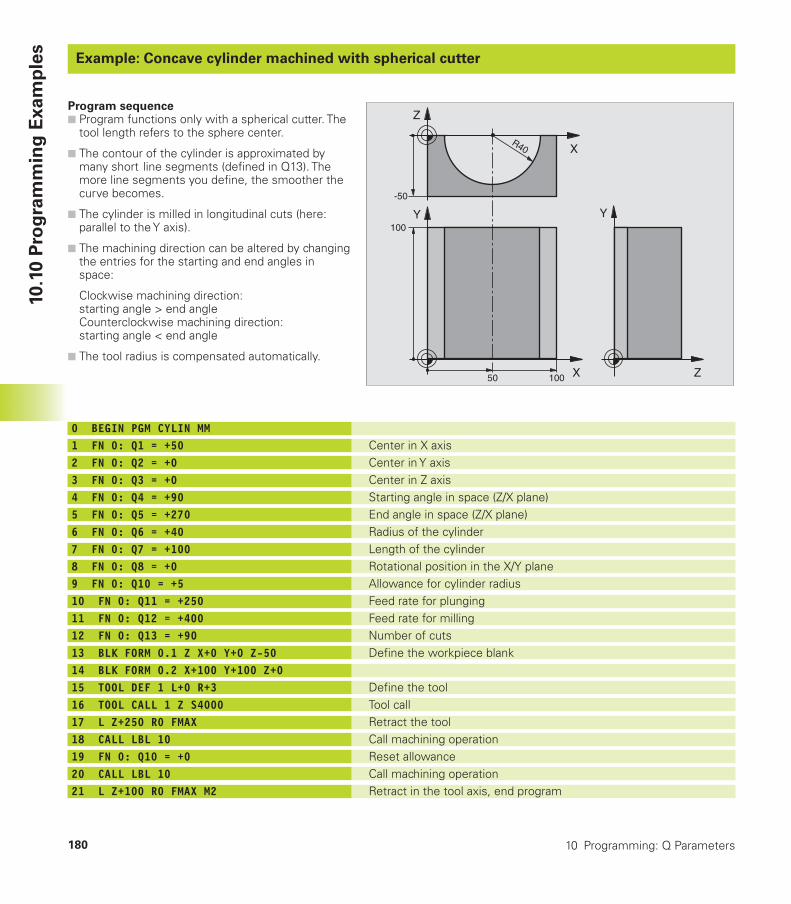
10 Programming: Q Parameters180
Example: Concave cylinder machined with spherical cutterExample: Concave cylinder machined with spherical cutter
Center in X axisCenter in Y axisCenter in Z axisStarting angle in space (Z/X plane)End angle in space (Z/X plane)Radius of the cylinderLength of the cylinderRotational position in the X/Y planeAllowance for cylinder radiusFeed rate for plungingFeed rate for millingNumber of cutsDefine the workpiece blank
Define the toolTool callRetract the toolCall machining operationReset allowanceCall machining operationRetract in the tool axis, end program
0 BEGIN PGM CYLIN MM1 FN 0: Q1 = +502 FN 0: Q2 = +03 FN 0: Q3 = +04 FN 0: Q4 = +905 FN 0: Q5 = +2706 FN 0: Q6 = +407 FN 0: Q7 = +1008 FN 0: Q8 = +09 FN 0: Q10 = +510 FN 0: Q11 = +25011 FN 0: Q12 = +40012 FN 0: Q13 = +9013 BLK FORM 0.1 Z X+0 Y+0 Z-5014 BLK FORM 0.2 X+100 Y+100 Z+015 TOOL DEF 1 L+0 R+316 TOOL CALL 1 Z S400017 L Z+250 R0 FMAX18 CALL LBL 1019 FN 0: Q10 = +020 CALL LBL 1021 L Z+100 R0 FMAX M2
Program sequence■ Program functions only with a spherical cutter. The
tool length refers to the sphere center.
■ The contour of the cylinder is approximated bymany short line segments (defined in Q13). Themore line segments you define, the smoother thecurve becomes.
■ The cylinder is milled in longitudinal cuts (here:parallel to the Y axis).
■ The machining direction can be altered by changingthe entries for the starting and end angles inspace:
Clockwise machining direction:starting angle > end angleCounterclockwise machining direction:starting angle < end angle
■ The tool radius is compensated automatically.
10.1
0 P
rog
ram
min
g E
xam
ple
s
X
Y
50 100
100
Z
Y
X
Z
-50
R40
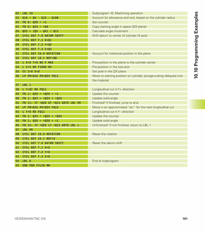
181HEIDENHAIN TNC 310
22 LBL 1023 Q16 = Q6 - Q10 - Q10824 FN 0: Q20 = +125 FN 0: Q24 = +Q426 Q25 = (Q5 - Q4) / Q1327 CYCL DEF 7.0 DATUM SHIFT28 CYCL DEF 7.1 X+Q129 CYCL DEF 7.2 Y+Q230 CYCL DEF 7.3 Z+Q331 CYCL DEF 10.0 ROTATION32 CYCL DEF 10.1 ROT+Q833 L X+0 Y+0 R0 F MAX34 L Z+5 R0 F1000 M335 CC Z+0 X+036 LP PR+Q16 PA+Q24 FQ11
37 LBL 138 L Y+Q7 R0 FQ1139 FN 1: Q20 = +Q20 + +140 FN 1: Q24 = +Q24 + +Q2541 FN 11: IF +Q20 GT +Q13 GOTO LBL 9942 LP PR+Q16 PA+Q24 FQ1243 L Y+0 R0 FQ1144 FN 1: Q24 = +Q24 + +Q2545 FN 1: Q20 = +Q20 + +146 FN 12: IF +Q20 LT +Q13 GOTO LBL 147 LBL 9948 CYCL DEF 10.0 ROTATION49 CYCL DEF 10.1 ROT+050 CYCL DEF 7.0 DATUM SHIFT51 CYCL DEF 7.1 X+052 CYCL DEF 7.2 Y+053 CYCL DEF 7.3 Z+054 LBL 055 END PGM CYLIN MM
Subprogram 10: Machining operationAccount for allowance and tool, based on the cylinder radiusSet counterCopy starting angle in space (Z/X plane)Calculate angle incrementShift datum to center of cylinder (X axis)
Account for rotational position in the plane
Pre-position in the plane to the cylinder centerPre-position in the tool axisSet pole in the Z/X planeMove to starting position on cylinder, plunge-cutting obliquely intothe material
Longitudinal cut in Y+ directionUpdate the counterUpdate solid angleFinished? If finished, jump to end.Move in an approximated “arc” for the next longitudinal cutLongitudinal cut in Y– directionUpdate the counterUpdate solid angleUnfinished? If not finished, return to LBL 1
Reset the rotation
Reset the datum shift
End of subprogram
10.1
0 P
rog
ram
min
g E
xam
ple
s
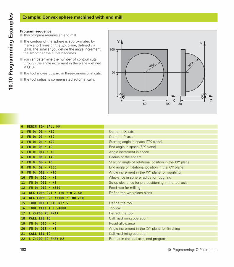
10 Programming: Q Parameters182
Example: Convex sphere machined with end millExample: Convex sphere machined with end mill
Center in X axisCenter in Y axisStarting angle in space (Z/X plane)End angle in space (Z/X plane)Angle increment in spaceRadius of the sphereStarting angle of rotational position in the X/Y planeEnd angle of rotational position in the X/Y planeAngle increment in the X/Y plane for roughingAllowance in sphere radius for roughingSetup clearance for pre-positioning in the tool axisFeed rate for millingDefine the workpiece blank
Define the toolTool callRetract the toolCall machining operationReset allowanceAngle increment in the X/Y plane for finishingCall machining operationRetract in the tool axis, end program
0 BEGIN PGM BALL MM1 FN 0: Q1 = +502 FN 0: Q2 = +503 FN 0: Q4 = +904 FN 0: Q5 = +05 FN 0: Q14 = +56 FN 0: Q6 = +457 FN 0: Q8 = +08 FN 0: Q9 = +3609 FN 0: Q18 = +1010 FN 0: Q10 = +511 FN 0: Q11 = +212 FN 0: Q12 = +35013 BLK FORM 0.1 Z X+0 Y+0 Z-5014 BLK FORM 0.2 X+100 Y+100 Z+015 TOOL DEF 1 L+0 R+7.516 TOOL CALL 1 Z S400017 L Z+250 R0 FMAX18 CALL LBL 1019 FN 0: Q10 = +020 FN 0: Q18 = +521 CALL LBL 1022 L Z+100 R0 FMAX M2
Program sequence■ This program requires an end mill.
■ The contour of the sphere is approximated bymany short lines (in the Z/X plane, defined viaQ14). The smaller you define the angle increment,the smoother the curve becomes.
■ You can determine the number of contour cutsthrough the angle increment in the plane (definedin Q18).
■ The tool moves upward in three-dimensional cuts.
■ The tool radius is compensated automatically.
X
Y
50 100
100
Z
Y
-50
R45
50
R45
10.1
0 P
rog
ram
min
g E
xam
ple
s
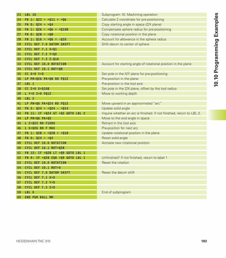
183HEIDENHAIN TNC 310
10.1
0 P
rog
ram
min
g E
xam
ple
s23 LBL 1024 FN 1: Q23 = +Q11 + +Q625 FN 0: Q24 = +Q426 FN 1: Q26 = +Q6 + +Q10827 FN 0: Q28 = +Q828 FN 1: Q16 = +Q6 + -Q1029 CYCL DEF 7.0 DATUM SHIFT30 CYCL DEF 7.1 X+Q131 CYCL DEF 7.2 Y+Q232 CYCL DEF 7.3 Z-Q1633 CYCL DEF 10.0 ROTATION34 CYCL DEF 10.1 ROT+Q835 CC X+0 Y+036 LP PR+Q26 PA+Q8 R0 FQ1237 LBL 138 CC Z+0 X+Q10839 L Y+0 Z+0 FQ1240 LBL 241 LP PR+Q6 PA+Q24 R0 FQ1242 FN 2: Q24 = +Q24 - +Q1443 FN 11: IF +Q24 GT +Q5 GOTO LBL 244 LP PR+Q6 PA+Q545 L Z+Q23 R0 F100046 L X+Q26 R0 F MAX47 FN 1: Q28 = +Q28 + +Q1848 FN 0: Q24 = +Q449 CYCL DEF 10.0 ROTATION50 CYCL DEF 10.1 ROT+Q2851 FN 12: IF +Q28 LT +Q9 GOTO LBL 152 FN 9: IF +Q28 EQU +Q9 GOTO LBL 153 CYCL DEF 10.0 ROTATION54 CYCL DEF 10.1 ROT+055 CYCL DEF 7.0 DATUM SHIFT56 CYCL DEF 7.1 X+057 CYCL DEF 7.2 Y+058 CYCL DEF 7.3 Z+059 LBL 060 END PGM BALL MM
Subprogram 10: Machining operationCalculate Z coordinate for pre-positioningCopy starting angle in space (Z/X plane)Compensate sphere radius for pre-positioningCopy rotational position in the planeAccount for allowance in the sphere radiusShift datum to center of sphere
Account for starting angle of rotational position in the plane
Set pole in the X/Y plane for pre-positioningPre-position in the planePre-position in the tool axisSet pole in the Z/X plane, offset by the tool radiusMove to working depth
Move upward in an approximated “arc”Update solid angleInquire whether an arc is finished. If not finished, return to LBL 2.Move to the end angle in spaceRetract in the tool axisPre-position for next arcUpdate rotational position in the planeReset solid angleActivate new rotational position
Unfinished? If not finished, return to label 1Reset the rotation
Reset the datum shift
End of subprogram

Test Runand Program Run
11
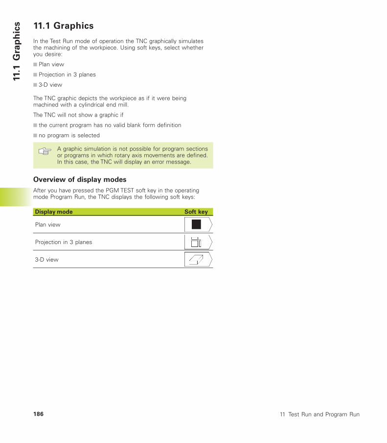
11 Test Run and Program Run186
11.1
Gra
ph
ics 11.1 Graphics
In the Test Run mode of operation the TNC graphically simulatesthe machining of the workpiece. Using soft keys, select whetheryou desire:
■ Plan view
■ Projection in 3 planes
■ 3-D view
The TNC graphic depicts the workpiece as if it were beingmachined with a cylindrical end mill.
The TNC will not show a graphic if
■ the current program has no valid blank form definition
■ no program is selected
A graphic simulation is not possible for program sectionsor programs in which rotary axis movements are defined.In this case, the TNC will display an error message.
Overview of display modes
After you have pressed the PGM TEST soft key in the operatingmode Program Run, the TNC displays the following soft keys:
Display mode Soft key
Plan view
Projection in 3 planes
3-D view
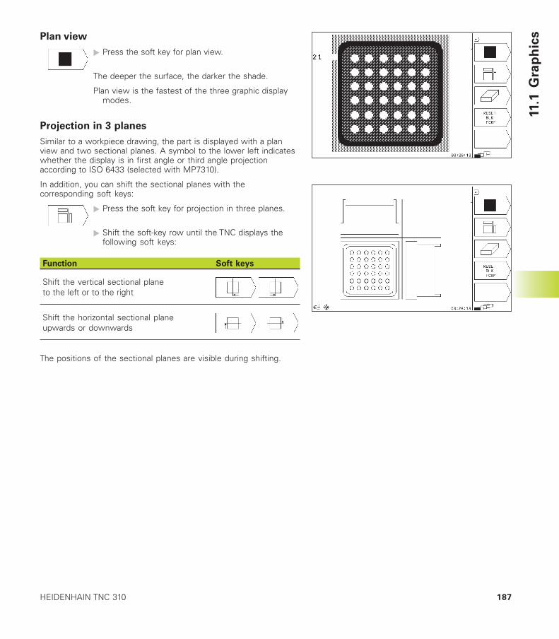
187HEIDENHAIN TNC 310
11.1
Gra
ph
icsPlan view
� Press the soft key for plan view.
The deeper the surface, the darker the shade.
Plan view is the fastest of the three graphic displaymodes.
Projection in 3 planes
Similar to a workpiece drawing, the part is displayed with a planview and two sectional planes. A symbol to the lower left indicateswhether the display is in first angle or third angle projectionaccording to ISO 6433 (selected with MP7310).
In addition, you can shift the sectional planes with thecorresponding soft keys:
� Press the soft key for projection in three planes.
� Shift the soft-key row until the TNC displays thefollowing soft keys:
Function Soft keys
Shift the vertical sectional planeto the left or to the right
Shift the horizontal sectional planeupwards or downwards
The positions of the sectional planes are visible during shifting.
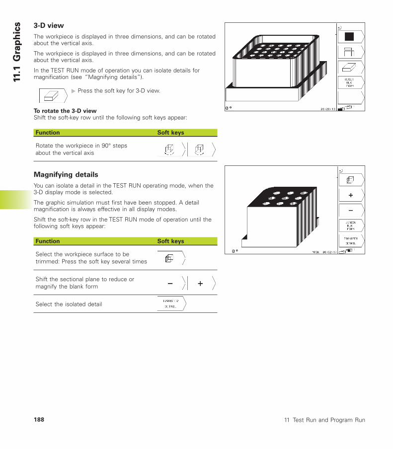
11 Test Run and Program Run188
11.1
Gra
ph
ics
11.1
Gra
ph
ics 3-D view
The workpiece is displayed in three dimensions, and can be rotatedabout the vertical axis.
The workpiece is displayed in three dimensions, and can be rotatedabout the vertical axis.
In the TEST RUN mode of operation you can isolate details formagnification (see “Magnifying details”).
� Press the soft key for 3-D view.
To rotate the 3-D viewShift the soft-key row until the following soft keys appear:
Function Soft keys
Rotate the workpiece in 90° stepsabout the vertical axis
Magnifying details
You can isolate a detail in the TEST RUN operating mode, when the3-D display mode is selected.
The graphic simulation must first have been stopped. A detailmagnification is always effective in all display modes.
Shift the soft-key row in the TEST RUN mode of operation until thefollowing soft keys appear:
Function Soft keys
Select the workpiece surface to betrimmed: Press the soft key several times
Shift the sectional plane to reduce ormagnify the blank form
Select the isolated detail
189HEIDENHAIN TNC 310
11.1
Gra
ph
icsTo change the detail magnification:
The soft keys are listed in the table above.
� Interrupt the graphic simulation, if necessary.
�Select the workpiece surface with the correspondingsoft key (see table).
� To reduce or magnify the blank form, press the minusor plus soft key, respectively.
� To select the isolated detail, press the TRANSFERDETAIL soft key
�Restart the test run or program run.
Repeating graphic simulation
A part program can be graphically simulated as often as desired,either with the complete workpiece or with a detail of it.
Function Soft key
Restore workpiece blank to the detailmagnification in which it was last shown
Reset detail magnification so that the machinedworkpiece or workpiece blank is displayed as itwas programmed with BLK FORM
The WINDOW BLK FORM soft key will return the blankform to its original shape or size, even if a detail hasbeen isolated and not yet magnified with TRANSFERDETAIL.
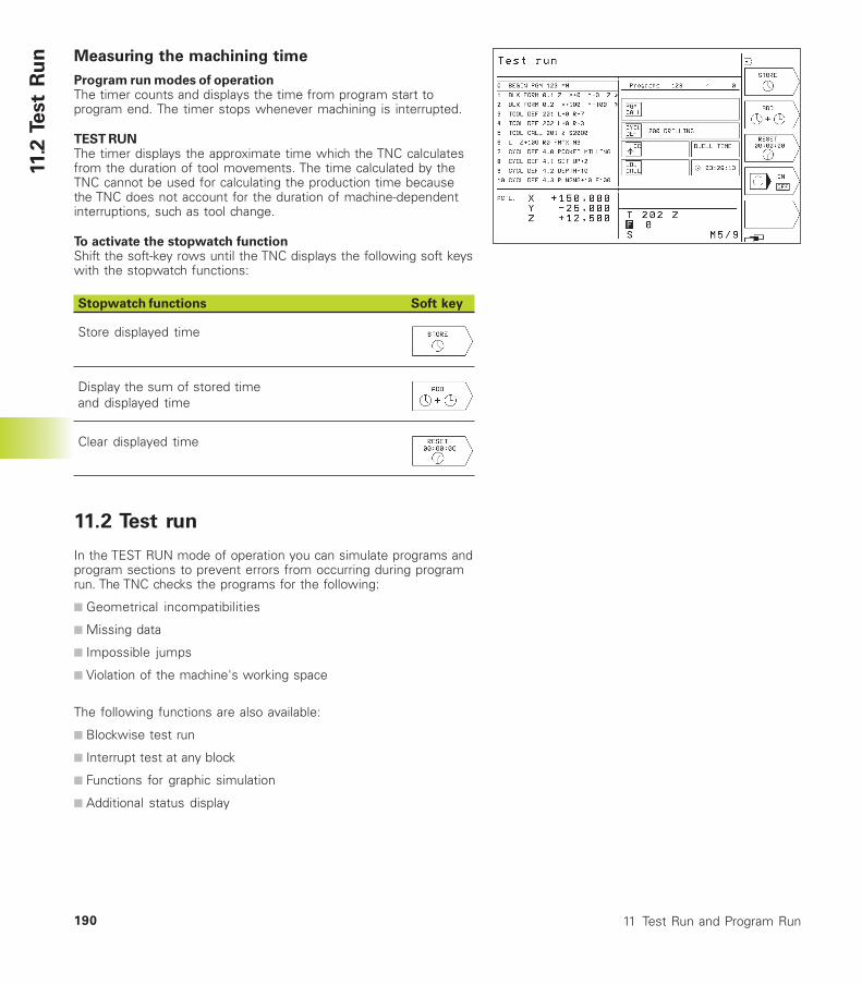
11 Test Run and Program Run190
11.2
Test
Ru
n Measuring the machining time
Program run modes of operationThe timer counts and displays the time from program start toprogram end. The timer stops whenever machining is interrupted.
TEST RUNThe timer displays the approximate time which the TNC calculatesfrom the duration of tool movements. The time calculated by theTNC cannot be used for calculating the production time becausethe TNC does not account for the duration of machine-dependentinterruptions, such as tool change.
To activate the stopwatch functionShift the soft-key rows until the TNC displays the following soft keyswith the stopwatch functions:
Stopwatch functions Soft key
Store displayed time
Display the sum of stored timeand displayed time
Clear displayed time
11.2 Test run
In the TEST RUN mode of operation you can simulate programs andprogram sections to prevent errors from occurring during programrun. The TNC checks the programs for the following:
■ Geometrical incompatibilities
■ Missing data
■ Impossible jumps
■ Violation of the machine's working space
The following functions are also available:
■ Blockwise test run
■ Interrupt test at any block
■ Functions for graphic simulation
■ Additional status display
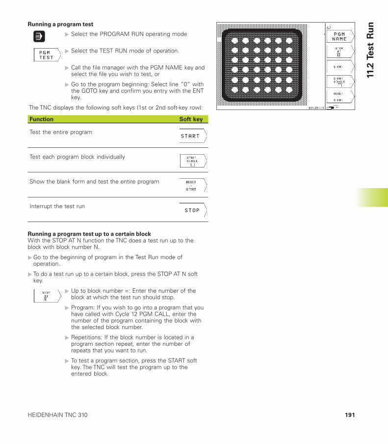
191HEIDENHAIN TNC 310
11.2
Test
Ru
nRunning a program test
� Select the PROGRAM RUN operating mode
� Select the TEST RUN mode of operation.
� Call the file manager with the PGM NAME key andselect the file you wish to test, or
� Go to the program beginning: Select line “0” withthe GOTO key and confirm you entry with the ENTkey.
The TNC displays the following soft keys (1st or 2nd soft-key row):
Function Soft key
Test the entire program
Test each program block individually
Show the blank form and test the entire program
Interrupt the test run
Running a program test up to a certain blockWith the STOP AT N function the TNC does a test run up to theblock with block number N.
�Go to the beginning of program in the Test Run mode ofoperation.
� To do a test run up to a certain block, press the STOP AT N softkey.
� Up to block number =: Enter the number of theblock at which the test run should stop.
� Program: If you wish to go into a program that youhave called with Cycle 12 PGM CALL, enter thenumber of the program containing the block withthe selected block number.
� Repetitions: If the block number is located in aprogram section repeat, enter the number ofrepeats that you want to run.
� To test a program section, press the START softkey. The TNC will test the program up to theentered block.
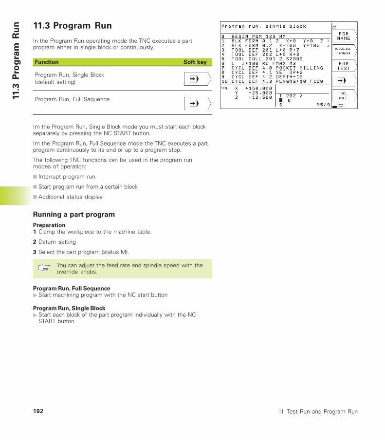
11 Test Run and Program Run192
11.3
Pro
gra
m R
un 11.3 Program Run
In the Program Run operating mode the TNC executes a partprogram either in single block or continuously.
Function Soft key
Program Run, Single Block(default setting)
Program Run, Full Sequence
Im the Program Run, Single Block mode you must start each blockseparately by pressing the NC START button.
Im the Program Run, Full Sequence mode the TNC executes a partprogram continuously to its end or up to a program stop.
The following TNC functions can be used in the program runmodes of operation:
■ Interrupt program run
■ Start program run from a certain block
■ Additional status display
Running a part program
Preparation1 Clamp the workpiece to the machine table.
2 Datum setting
3 Select the part program (status M).
You can adjust the feed rate and spindle speed with theoverride knobs.
Program Run, Full Sequence�Start machining program with the NC start button
Program Run, Single Block�Start each block of the part program individually with the NC
START button.
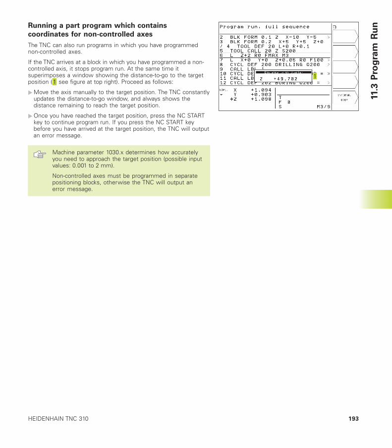
193HEIDENHAIN TNC 310
11.3
Pro
gra
m R
unRunning a part program which contains
coordinates for non-controlled axes
The TNC can also run programs in which you have programmednon-controlled axes.
If the TNC arrives at a block in which you have programmed a non-controlled axis, it stops program run. At the same time itsuperimposes a window showing the distance-to-go to the targetposition ( see figure at top right). Proceed as follows:
�Move the axis manually to the target position. The TNC constantlyupdates the distance-to-go window, and always shows thedistance remaining to reach the target position.
�Once you have reached the target position, press the NC STARTkey to continue program run. If you press the NC START keybefore you have arrived at the target position, the TNC will outputan error message.
Machine parameter 1030.x determines how accuratelyyou need to approach the target position (possible inputvalues: 0.001 to 2 mm).
Non-controlled axes must be programmed in separatepositioning blocks, otherwise the TNC will output anerror message.
11 Test Run and Program Run194
11.3
Pro
gra
m R
un Interrupting machining
There are several ways to interrupt a program run:
■ Programmed interruptions
■ Machine STOP button
■ Switching to Program Run, Single Block
If the TNC registers an error during program run, it automaticallyinterrupts the machining process.
Programmed interruptionsYou can program interruptions directly in the part program. The TNCinterrupts the program run at a block containing one of thefollowing entries:
■ STOP (with and without a miscellaneous function)
■ Miscellaneous functions M0, M1 (see „11.5 Optional Program RunInterruption“), M2 or M30
■ Miscellaneous function M6 (determined by the machine toolbuilder)
Interruption with NC STOP button�Press the NC STOP button: The block which the TNC is currently
executing is not completed. The asterisk in the status displayblinks.
� If you do not wish to continue the machining process you canreset the TNC with the STOP soft key. The asterisk in the statusdisplay goes out. In this case, the program must be restartedfrom the program beginning.
Interruption of machining by switching to the Program Run,Single Block mode of operation.You can interrupt a program that is being run in the Program Run,Full Sequence mode of operation by switching to Program Run,Single Block. The TNC interrupts the machining process at the endof the current block.
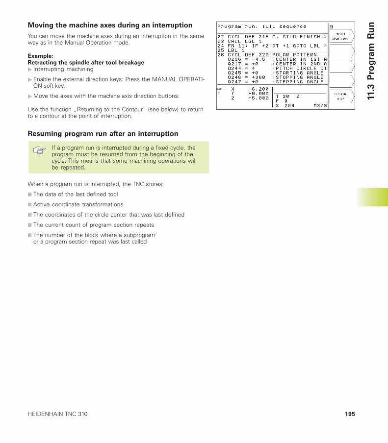
195HEIDENHAIN TNC 310
Moving the machine axes during an interruption
You can move the machine axes during an interruption in the sameway as in the Manual Operation mode.
Example:Retracting the spindle after tool breakage� Interrupting machining
�Enable the external direction keys: Press the MANUAL OPERATI-ON soft key.
�Move the axes with the machine axis direction buttons.
Use the function „Returning to the Contour“ (see below) to returnto a contour at the point of interruption.
Resuming program run after an interruption
If a program run is interrupted during a fixed cycle, theprogram must be resumed from the beginning of thecycle. This means that some machining operations willbe repeated.
When a program run is interrupted, the TNC stores:
■ The data of the last defined tool
■ Active coordinate transformations
■ The coordinates of the circle center that was last defined
■ The current count of program section repeats
■ The number of the block where a subprogramor a program section repeat was last called
11.3
Pro
gra
m R
un
11 Test Run and Program Run196
11.3
Pro
gra
m R
un Resuming program run with the NC START button
You can resume program run by pressing the NC START button ifthe program was interrupted in one of the following ways:
■ NC STOP button was pressed
■ A programmed interruption
■ The EMERGENCY STOP button was pressed (machine-dependentfunction)
If you interrupted program run with the STOP soft key,you can select another block with the GOTO key andresume machining there.
If you select block 0, the TNC resets all stored data (tooldata, etc.)
If you interrupted program run during a program sectionrepeat, you can only use GOTO to select other blockswithin the program section repeat.
Resuming program run after an error■ If the error message is not blinking
�Remove the cause of the error.
� To clear the error message from the screen, press the CE key.
�Restart the program, or resume program run at the place at whichit was interrupted.
■ If the error message is blinking
�Switch off the TNC and the machine.
�Remove the cause of the error.
�Start again.
If you cannot correct the error, write down the error message andcontact your repair service agency.
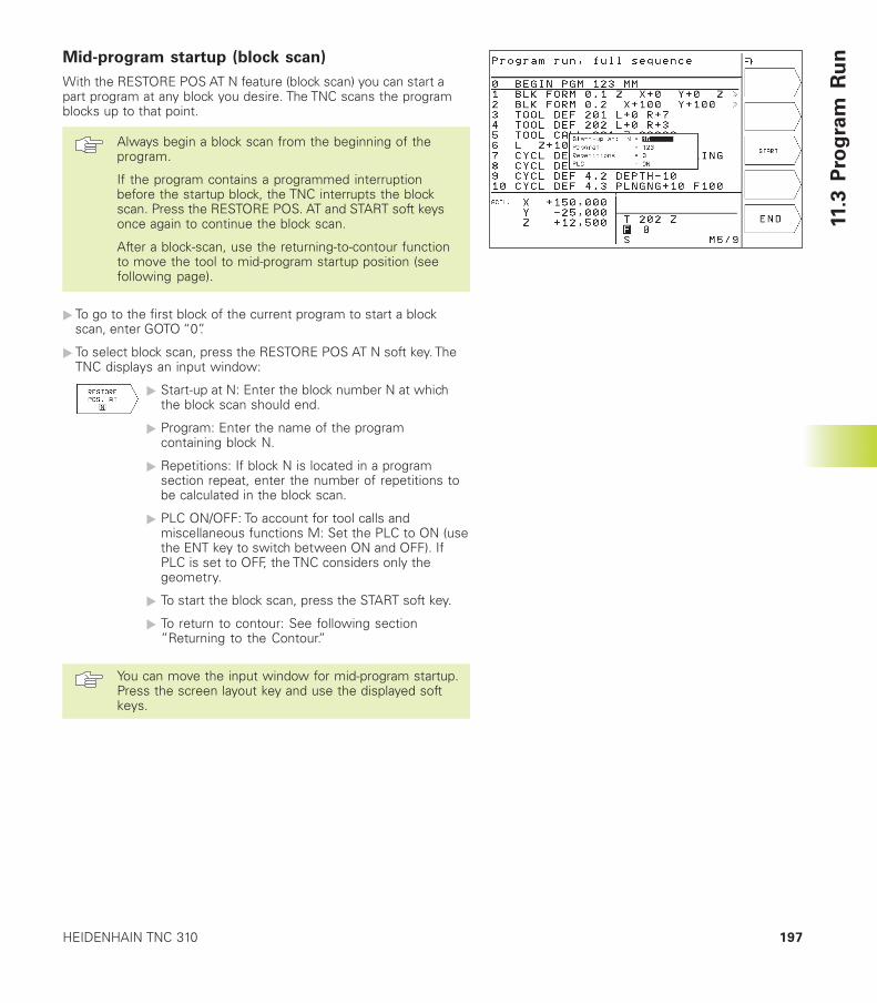
197HEIDENHAIN TNC 310
Mid-program startup (block scan)
With the RESTORE POS AT N feature (block scan) you can start apart program at any block you desire. The TNC scans the programblocks up to that point.
Always begin a block scan from the beginning of theprogram.
If the program contains a programmed interruptionbefore the startup block, the TNC interrupts the blockscan. Press the RESTORE POS. AT and START soft keysonce again to continue the block scan.
After a block-scan, use the returning-to-contour functionto move the tool to mid-program startup position (seefollowing page).
� To go to the first block of the current program to start a blockscan, enter GOTO “0”.
� To select block scan, press the RESTORE POS AT N soft key. TheTNC displays an input window:
� Start-up at N: Enter the block number N at whichthe block scan should end.
� Program: Enter the name of the programcontaining block N.
� Repetitions: If block N is located in a programsection repeat, enter the number of repetitions tobe calculated in the block scan.
� PLC ON/OFF: To account for tool calls andmiscellaneous functions M: Set the PLC to ON (usethe ENT key to switch between ON and OFF). IfPLC is set to OFF, the TNC considers only thegeometry.
� To start the block scan, press the START soft key.
� To return to contour: See following section”Returning to the Contour.”
You can move the input window for mid-program startup.Press the screen layout key and use the displayed softkeys.
11.3
Pro
gra
m R
un
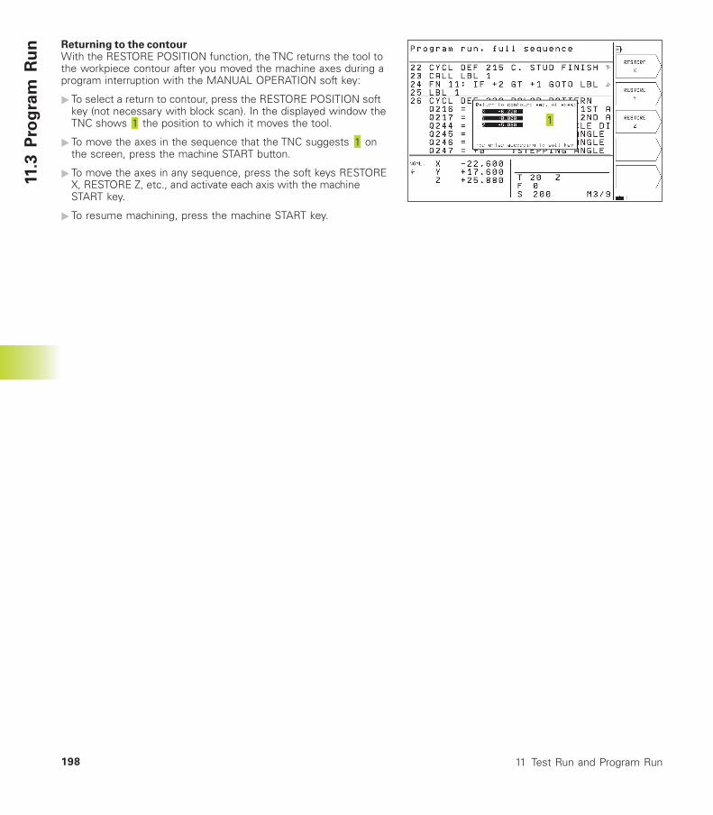
11 Test Run and Program Run198
Returning to the contourWith the RESTORE POSITION function, the TNC returns the tool tothe workpiece contour after you moved the machine axes during aprogram interruption with the MANUAL OPERATION soft key:
� To select a return to contour, press the RESTORE POSITION softkey (not necessary with block scan). In the displayed window theTNC shows the position to which it moves the tool.
� To move the axes in the sequence that the TNC suggests onthe screen, press the machine START button.
� To move the axes in any sequence, press the soft keys RESTOREX, RESTORE Z, etc., and activate each axis with the machineSTART key.
� To resume machining, press the machine START key.
11.3
Pro
gra
m R
un
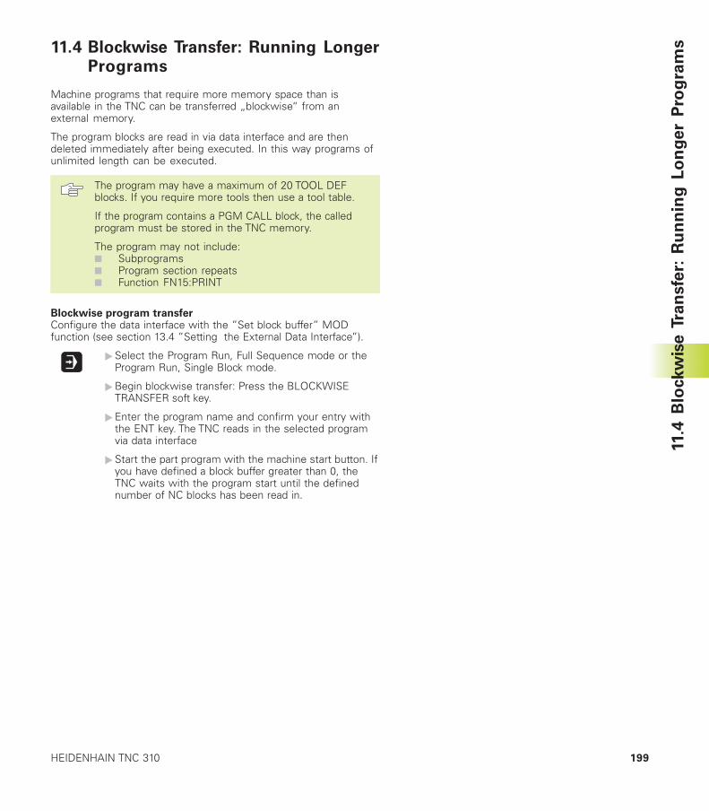
199HEIDENHAIN TNC 310
11.4
Blo
ckw
ise T
ran
sfe
r: R
un
nin
g L
on
ge
r P
rog
ram
s11.4 Blockwise Transfer: Running LongerPrograms
Machine programs that require more memory space than isavailable in the TNC can be transferred „blockwise“ from anexternal memory.
The program blocks are read in via data interface and are thendeleted immediately after being executed. In this way programs ofunlimited length can be executed.
The program may have a maximum of 20 TOOL DEFblocks. If you require more tools then use a tool table.
If the program contains a PGM CALL block, the calledprogram must be stored in the TNC memory.
The program may not include:■ Subprograms■ Program section repeats■ Function FN15:PRINT
Blockwise program transferConfigure the data interface with the ”Set block buffer” MODfunction (see section 13.4 ”Setting the External Data Interface”).
�Select the Program Run, Full Sequence mode or theProgram Run, Single Block mode.
�Begin blockwise transfer: Press the BLOCKWISETRANSFER soft key.
�Enter the program name and confirm your entry withthe ENT key. The TNC reads in the selected programvia data interface
�Start the part program with the machine start button. Ifyou have defined a block buffer greater than 0, theTNC waits with the program start until the definednumber of NC blocks has been read in.
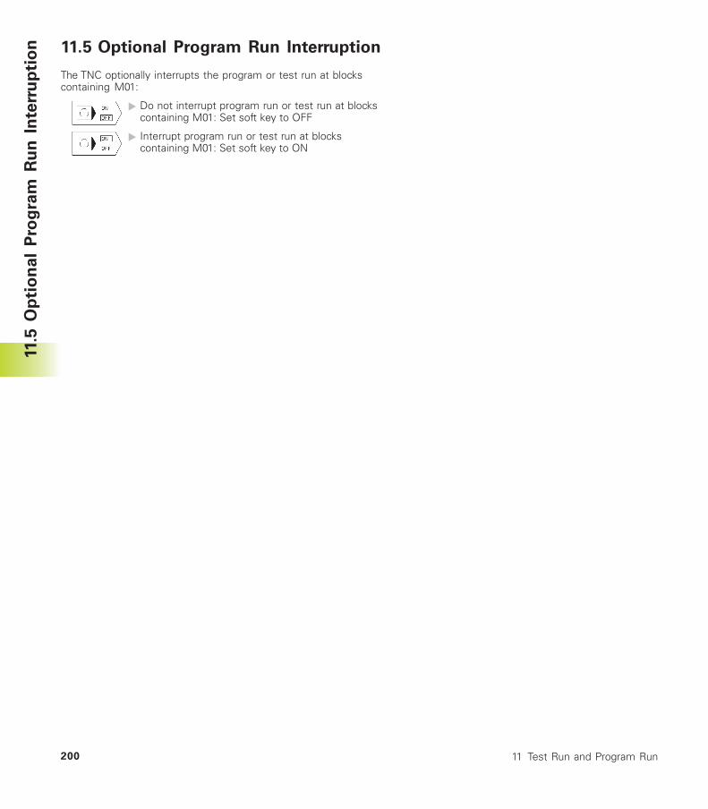
11 Test Run and Program Run200
11.5 Optional Program Run Interruption
The TNC optionally interrupts the program or test run at blockscontaining M01:
� Do not interrupt program run or test run at blockscontaining M01: Set soft key to OFF
� Interrupt program run or test run at blockscontaining M01: Set soft key to ON
11.5
Op
tio
nal
Pro
gra
m R
un
In
terr
up
tio
n
3-D Touch Probes
12
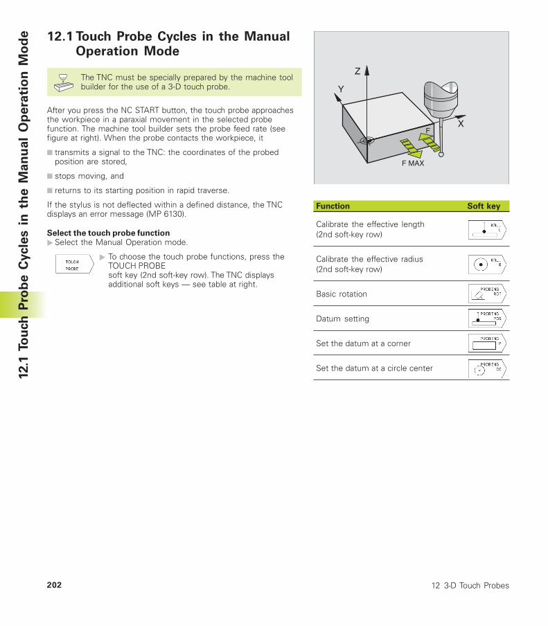
12 3-D Touch Probes202
12.1 Touch Probe Cycles in the ManualOperation Mode
The TNC must be specially prepared by the machine toolbuilder for the use of a 3-D touch probe.
After you press the NC START button, the touch probe approachesthe workpiece in a paraxial movement in the selected probefunction. The machine tool builder sets the probe feed rate (seefigure at right). When the probe contacts the workpiece, it
■ transmits a signal to the TNC: the coordinates of the probedposition are stored,
■ stops moving, and
■ returns to its starting position in rapid traverse.
If the stylus is not deflected within a defined distance, the TNCdisplays an error message (MP 6130).
Select the touch probe function�Select the Manual Operation mode.
� To choose the touch probe functions, press theTOUCH PROBEsoft key (2nd soft-key row). The TNC displaysadditional soft keys — see table at right.
Function Soft key
Calibrate the effective length(2nd soft-key row)
Calibrate the effective radius(2nd soft-key row)
Basic rotation
Datum setting
Set the datum at a corner
Set the datum at a circle center
12.1
To
uch
Pro
be C
ycle
s i
n t
he M
an
ual
Op
era
tio
n M
od
e
Y
X
Z
F
F MAX
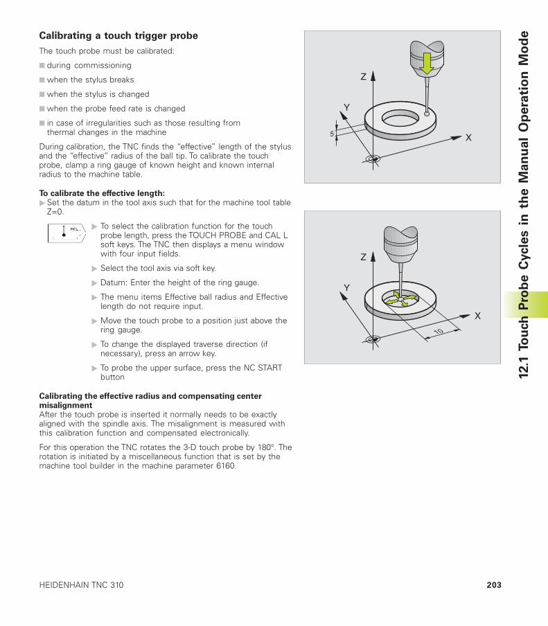
203HEIDENHAIN TNC 310
Calibrating a touch trigger probe
The touch probe must be calibrated:
■ during commissioning
■ when the stylus breaks
■ when the stylus is changed
■ when the probe feed rate is changed
■ in case of irregularities such as those resulting fromthermal changes in the machine
During calibration, the TNC finds the “effective” length of the stylusand the “effective” radius of the ball tip. To calibrate the touchprobe, clamp a ring gauge of known height and known internalradius to the machine table.
To calibrate the effective length:�Set the datum in the tool axis such that for the machine tool table
Z=0.
� To select the calibration function for the touchprobe length, press the TOUCH PROBE and CAL Lsoft keys. The TNC then displays a menu windowwith four input fields.
� Select the tool axis via soft key.
� Datum: Enter the height of the ring gauge.
� The menu items Effective ball radius and Effectivelength do not require input.
� Move the touch probe to a position just above thering gauge.
� To change the displayed traverse direction (ifnecessary), press an arrow key.
� To probe the upper surface, press the NC STARTbutton
Calibrating the effective radius and compensating centermisalignmentAfter the touch probe is inserted it normally needs to be exactlyaligned with the spindle axis. The misalignment is measured withthis calibration function and compensated electronically.
For this operation the TNC rotates the 3-D touch probe by 180°. Therotation is initiated by a miscellaneous function that is set by themachine tool builder in the machine parameter 6160.
12.1
To
uch
Pro
be C
ycle
s i
n t
he M
an
ual
Op
era
tio
n M
od
e
5
Y
X
Z
Y
X
Z
10
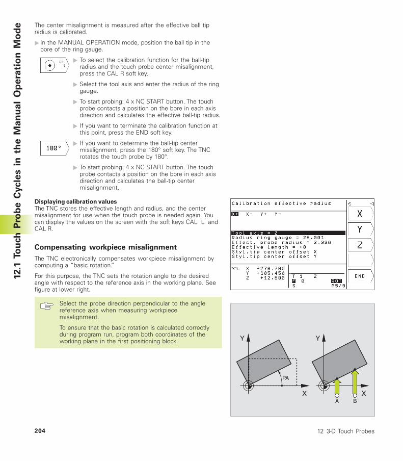
12 3-D Touch Probes204
X
Y
PA
X
Y
A B
The center misalignment is measured after the effective ball tipradius is calibrated.
� In the MANUAL OPERATION mode, position the ball tip in thebore of the ring gauge.
� To select the calibration function for the ball-tipradius and the touch probe center misalignment,press the CAL R soft key.
� Select the tool axis and enter the radius of the ringgauge.
� To start probing: 4 x NC START button. The touchprobe contacts a position on the bore in each axisdirection and calculates the effective ball-tip radius.
� If you want to terminate the calibration function atthis point, press the END soft key.
� If you want to determine the ball-tip centermisalignment, press the 180° soft key. The TNCrotates the touch probe by 180°.
� To start probing: 4 x NC START button. The touchprobe contacts a position on the bore in each axisdirection and calculates the ball-tip centermisalignment.
Displaying calibration valuesThe TNC stores the effective length and radius, and the centermisalignment for use when the touch probe is needed again. Youcan display the values on the screen with the soft keys CAL L andCAL R.
Compensating workpiece misalignment
The TNC electronically compensates workpiece misalignment bycomputing a “basic rotation.”
For this purpose, the TNC sets the rotation angle to the desiredangle with respect to the reference axis in the working plane. Seefigure at lower right.
Select the probe direction perpendicular to the anglereference axis when measuring workpiecemisalignment.
To ensure that the basic rotation is calculated correctlyduring program run, program both coordinates of theworking plane in the first positioning block.
12.1
To
uch
Pro
be C
ycle
s i
n t
he M
an
ual
Op
era
tio
n M
od
e
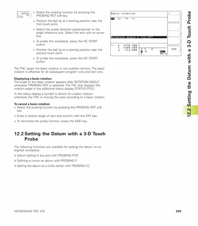
205HEIDENHAIN TNC 310
� Select the probing function by pressing thePROBING ROT soft key.
� Position the ball tip at a starting position near thefirst touch point.
� Select the probe direction perpendicular to theangle reference axis: Select the axis with an arrowkey.
� To probe the workpiece, press the NC STARTbutton
� Position the ball tip at a starting position near thesecond touch point.
� To probe the workpiece, press the NC STARTbutton
The TNC saves the basic rotation in non-volatile memory. The basicrotation is effective for all subsequent program runs and test runs.
Displaying a basic rotationThe angle of the basic rotation appears after ROTATION ANGLEwhenever PROBING ROT is selected. The TNC also displays therotation angle in the additional status display (STATUS POS.) .
In the status display a symbol is shown for a basic rotationwhenever the TNC is moving the axes according to a basic rotation.
To cancel a basic rotation:�Select the probing function by pressing the PROBING ROT soft
key.
�Enter a rotation angle of zero and confirm with the ENT key.
� To terminate the probe function, press the END key.
12.2 Setting the Datum with a 3-D TouchProbe
The following functions are available for setting the datum on analigned workpiece:
■ Datum setting in any axis with PROBING POS
■ Defining a corner as datum with PROBING P
■ Setting the datum at a circle center with PROBING CC
12.2
Sett
ing
th
e D
atu
m w
ith
a 3
-D T
ou
ch
Pro
be
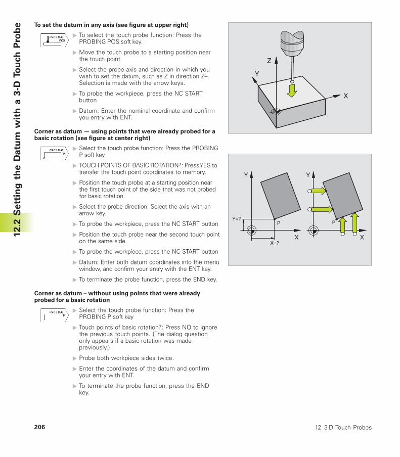
12 3-D Touch Probes206
To set the datum in any axis (see figure at upper right)
� To select the touch probe function: Press thePROBING POS soft key.
� Move the touch probe to a starting position nearthe touch point.
� Select the probe axis and direction in which youwish to set the datum, such as Z in direction Z–.Selection is made with the arrow keys.
� To probe the workpiece, press the NC STARTbutton
� Datum: Enter the nominal coordinate and confirmyou entry with ENT.
Corner as datum — using points that were already probed for abasic rotation (see figure at center right)
� Select the touch probe function: Press the PROBINGP soft key
� TOUCH POINTS OF BASIC ROTATION?: Press YES totransfer the touch point coordinates to memory.
� Position the touch probe at a starting position nearthe first touch point of the side that was not probedfor basic rotation.
� Select the probe direction: Select the axis with anarrow key.
� To probe the workpiece, press the NC START button
� Position the touch probe near the second touch pointon the same side.
� To probe the workpiece, press the NC START button
� Datum: Enter both datum coordinates into the menuwindow, and confirm your entry with the ENT key.
� To terminate the probe function, press the END key.
Corner as datum – without using points that were alreadyprobed for a basic rotation
� Select the touch probe function: Press thePROBING P soft key
� Touch points of basic rotation?: Press NO to ignorethe previous touch points. (The dialog questiononly appears if a basic rotation was madepreviously.)
� Probe both workpiece sides twice.
� Enter the coordinates of the datum and confirmyour entry with ENT.
� To terminate the probe function, press the ENDkey.
12.2
Sett
ing
th
e D
atu
m w
ith
a 3
-D T
ou
ch
Pro
be
P
X=?
Y=?
X
Y
P
X
Y
Y
X
Z
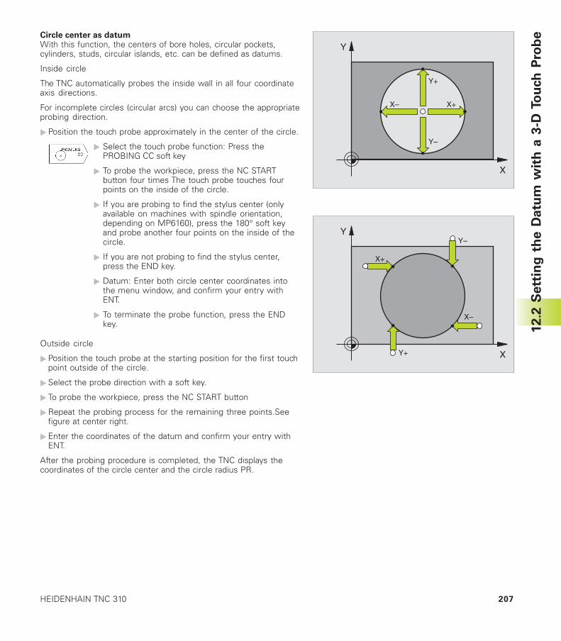
207HEIDENHAIN TNC 310
X
Y
X+X–
Y+
Y–
Circle center as datumWith this function, the centers of bore holes, circular pockets,cylinders, studs, circular islands, etc. can be defined as datums.
Inside circle
The TNC automatically probes the inside wall in all four coordinateaxis directions.
For incomplete circles (circular arcs) you can choose the appropriateprobing direction.
�Position the touch probe approximately in the center of the circle.
� Select the touch probe function: Press thePROBING CC soft key
� To probe the workpiece, press the NC STARTbutton four times The touch probe touches fourpoints on the inside of the circle.
� If you are probing to find the stylus center (onlyavailable on machines with spindle orientation,depending on MP6160), press the 180° soft keyand probe another four points on the inside of thecircle.
� If you are not probing to find the stylus center,press the END key.
� Datum: Enter both circle center coordinates intothe menu window, and confirm your entry withENT.
� To terminate the probe function, press the ENDkey.
Outside circle
�Position the touch probe at the starting position for the first touchpoint outside of the circle.
�Select the probe direction with a soft key.
� To probe the workpiece, press the NC START button
�Repeat the probing process for the remaining three points.Seefigure at center right.
�Enter the coordinates of the datum and confirm your entry withENT.
After the probing procedure is completed, the TNC displays thecoordinates of the circle center and the circle radius PR.
X
Y
X+
X–
Y+
Y–
12.2
Sett
ing
th
e D
atu
m w
ith
a 3
-D T
ou
ch
Pro
be
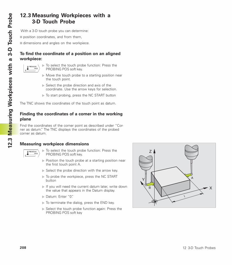
12 3-D Touch Probes208
12.3 Measuring Workpieces with a3-D Touch Probe
With a 3-D touch probe you can determine:
■ position coordinates, and from them,
■ dimensions and angles on the workpiece.
To find the coordinate of a position on an aligned
workpiece:
� To select the touch probe function: Press thePROBING POS soft key.
� Move the touch probe to a starting position nearthe touch point.
� Select the probe direction and axis of thecoordinate. Use the arrow keys for selection.
� To start probing, press the NC START button
The TNC shows the coordinates of the touch point as datum.
Finding the coordinates of a corner in the working
plane
Find the coordinates of the corner point as described under “Cor-ner as datum.” The TNC displays the coordinates of the probedcorner as datum.
Measuring workpiece dimensions
� To select the touch probe function: Press thePROBING POS soft key.
� Position the touch probe at a starting position nearthe first touch point A.
� Select the probe direction with the arrow key.
� To probe the workpiece, press the NC STARTbutton
� If you will need the current datum later, write downthe value that appears in the Datum display.
� Datum: Enter “0”.
� To terminate the dialog, press the END key.
� Select the touch probe function again: Press thePROBING POS soft key
12.3
Measu
rin
g W
ork
pie
ces w
ith
a 3
-D T
ou
ch
Pro
be
Y
X
Z
A
B
l
209HEIDENHAIN TNC 310
� Position the touch probe at a starting position nearthe second touch point B.
� Select the probe direction with an arrow key: Sameaxis but opposite direction as for A.
� To probe the workpiece, press the NC STARTbutton
The value displayed as Datum is the distance between the twopoints on the coordinate axis.
To return to the datum that was active before thelength measurement:
� To select the touch probe function: Press the PROBING POS softkey.
�Probe the first touch point again.
�Set the Datum to the value that you wrote down previously.
� To terminate the dialog, press the END key.
Measuring anglesYou can also use the 3-D touch probe to measure angles in theworking plane. You can measure
■ the angle between the angle reference axis and a workpieceside, or
■ the angle between two sides.
The measured angle is displayed as a value of maximum 90°.
To find the angle between the angle reference axis anda side of the workpiece:
� Select the touch probe function: Press thePROBING ROT soft key
� Rotation angle: If you will need the current basicrotation later, write down the value that appearsunder Rotation angle.
� Make a basic rotation with the side of theworkpiece (see “Compensating workpiecemisalignment”).
� Press the PROBING ROT soft key to display theangle between the angle reference axis and theside of the workpiece as the rotation angle.
� Cancel the basic rotation, or restore the previousbasic rotation:
� This is done by setting the Rotation angle to thevalue that you wrote down previously.
12.3
Measu
rin
g W
ork
pie
ces w
ith
a 3
-D T
ou
ch
Pro
be
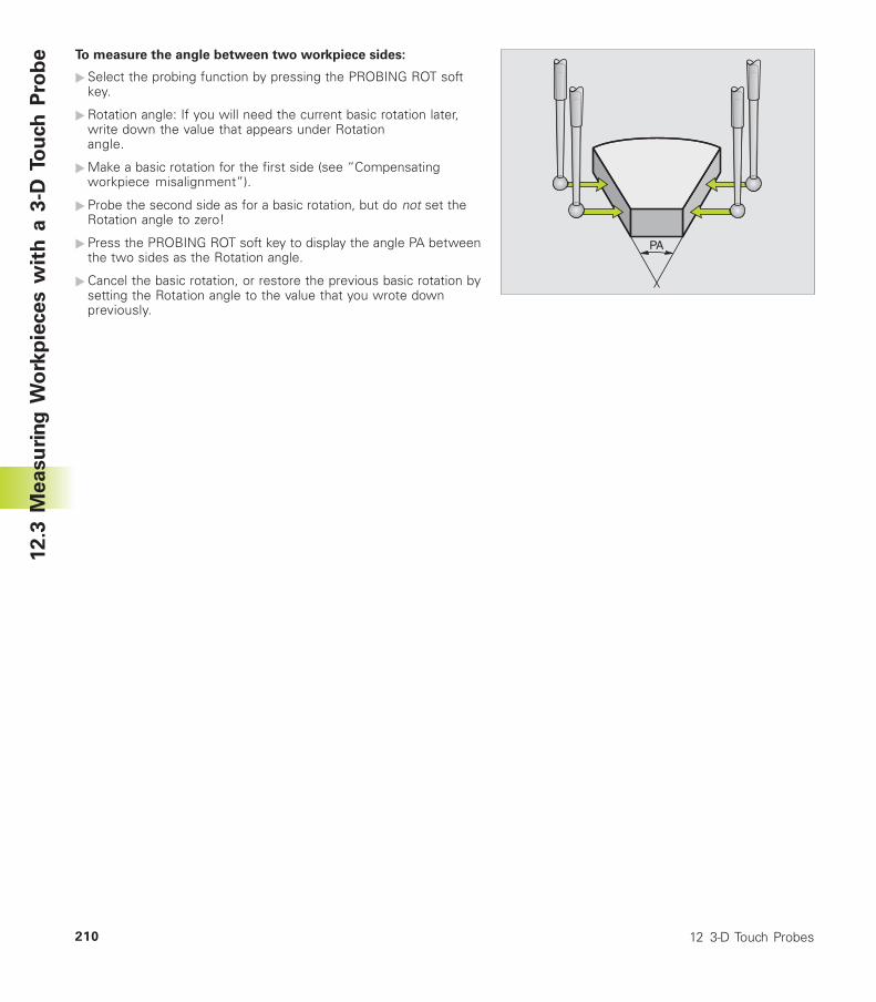
12 3-D Touch Probes210
To measure the angle between two workpiece sides:
�Select the probing function by pressing the PROBING ROT softkey.
�Rotation angle: If you will need the current basic rotation later,write down the value that appears under Rotationangle.
�Make a basic rotation for the first side (see “Compensatingworkpiece misalignment”).
�Probe the second side as for a basic rotation, but do not set theRotation angle to zero!
�Press the PROBING ROT soft key to display the angle PA betweenthe two sides as the Rotation angle.
�Cancel the basic rotation, or restore the previous basic rotation bysetting the Rotation angle to the value that you wrote downpreviously.
12.3
Measu
rin
g W
ork
pie
ces w
ith
a 3
-D T
ou
ch
Pro
be
PA
MOD Functions
13

13 MOD Functions212
13.1 Selecting, Changing and Exitingthe MOD Functions
The MOD functions provide additional displays and inputpossibilities.
To select the MOD functionsCall the mode of operation in which you wish to change the MODfunction.
� To select the MOD functions, press the MOD key. Thefigure at upper right shows the „MOD screen“.
You can make the following changes:
■ Select position display
■ Unit of measurement (mm/inches)
■ Enter code number
■ Set data interface
■ Machine-specific user parameters
■ Axis traverse limits
■ Display NC software number
■ Display PLC software number
To change the MOD functions:�Select the desired MOD function in the displayed menu with the
arrow keys.
�Press the ENT key repeatedly until the desired function ishighlighted, or� enter the appropriate numbers and confirm yourentry with ENT.
To exit the MOD functions:� To exit the MOD function, press the END key.
13.2 System Information
You can use the soft key INFO SYSTEM to display the followinginformation:
■ Free program memory
■ NC software number
■ PLC software number
are displayed on the TNC screen after the functions have beenselected.
13.1
Sele
cti
ng
, C
han
gin
g a
nd
Exit
ing
th
e M
OD
Fu
ncti
on
s;
13.2
Syste
m I
nfo
rmati
on
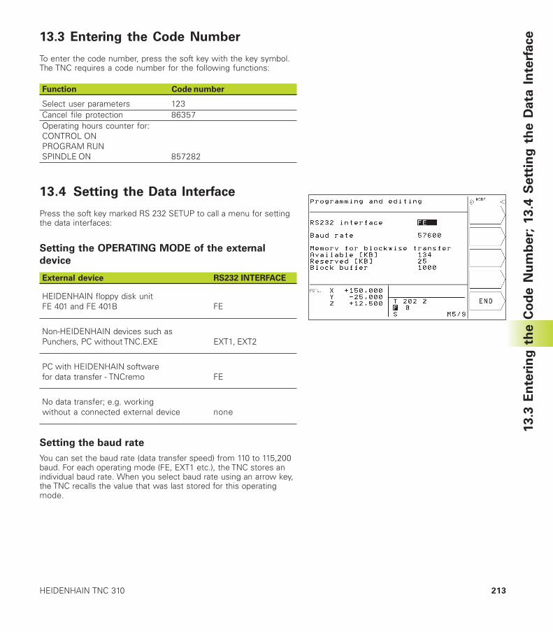
213HEIDENHAIN TNC 310
13.3 Entering the Code Number
To enter the code number, press the soft key with the key symbol.The TNC requires a code number for the following functions:
Function Code number
Select user parameters 123Cancel file protection 86357Operating hours counter for:CONTROL ONPROGRAM RUNSPINDLE ON 857282
13.4 Setting the Data Interface
Press the soft key marked RS 232 SETUP to call a menu for settingthe data interfaces:
Setting the OPERATING MODE of the external
device
External device RS232 INTERFACE
HEIDENHAIN floppy disk unitFE 401 and FE 401B FE
Non-HEIDENHAIN devices such asPunchers, PC without TNC.EXE EXT1, EXT2
PC with HEIDENHAIN softwarefor data transfer - TNCremo FE
No data transfer; e.g. workingwithout a connected external device none
Setting the baud rate
You can set the baud rate (data transfer speed) from 110 to 115,200baud. For each operating mode (FE, EXT1 etc.), the TNC stores anindividual baud rate. When you select baud rate using an arrow key,the TNC recalls the value that was last stored for this operatingmode.
13.3
En
teri
ng
th
e C
od
e N
um
ber;
13.4
Sett
ing
th
e D
ata
In
terf
ace
13 MOD Functions214
Creating the memory for blockwise transfer
In order to be able to edit other programs while blockwiseexecution is in progress, you need to create a memory forblockwise transfer.
The TNC shows the available free memory space. The reservedmemory space should be less than the total free memory spaceavailable.
Setting the block buffer
To ensure a continuous program run during blockwise transfer, theTNC needs a certain quantity of blocks stored in program memory.
In the block buffer you define how many NC blocks are read inthrough the data interface before the TNC begins the program run.The input value for the block buffer depends on the point intervalsin the part program. For very small point intervals, enter a largeblock buffer. For large point intervals, enter a small block buffer.Proposed value: 1000
Software for data transfer
For transfer of files to and from the TNC, we recommend using theHEIDENHAIN TNCremo data transfer software. With TNCremo, datatransfer is possible with all HEIDENHAIN controls via serialinterface.
Please contact your HEIDENHAIN agent if you would liketo receive the TNCremo data transfer software for anominal fee.
System requirements for TNCremo■ AT personal computer or compatible system
■ 640 KB working memory
■ 1 MB free memory space on your hard disk
■ One free serial interface
■ Operating system MS-DOS/PC-DOS 3.00 or later, Windows 3.1 orlater, OS/2
■ A Microsoft-compatible mouse (for ease of operation, notessential)
Installation under Windows�Start the SETUP.EXE installation program in the file manager
(explorer)
� Follow the instructions of the setup program
13.4
Sett
ing
th
e D
ata
In
terf
ace
215HEIDENHAIN TNC 310
Starting TNCremo under WindowsWindows 3.1, 3.11, NT:
�Double-click on the icon in the program group HEIDENHAINApplications
Windows 95:
�Click on <Start>, <Programs>, <HEIDENHAIN Applications>,<TNCremo>
When you start TNCremo for the first time, you will be asked for thetype of control you have connected, the interface (COM1 or COM2)and the data transfer speed. Enter the necessary information.
Data transfer between the TNC 310 and TNCremoEnsure that:
■ The TNC 310 is connected to the correct serial port on your PC
■ The data transfer speed set on the TNC is the same as that set onTNCremo
Once you have started TNCremo, you will see a list of all of the filesthat are stored in the active directory on the left of the windowUsing the menu items <Directory>, <Change>, you can change theactive directory or select another directory. To start data transferfrom the TNC (see „4.2 File Management“), select <Connect>,<File server>. TNCremo is now ready to receive data.
End TNCremoSelect the menu items <File>, <Exit>, or press the keycombination ALT+X
Refer also to the TNCremo help texts where all of thefunctions are explained in more detail.
13.4
Sett
ing
th
e D
ata
In
terf
ace
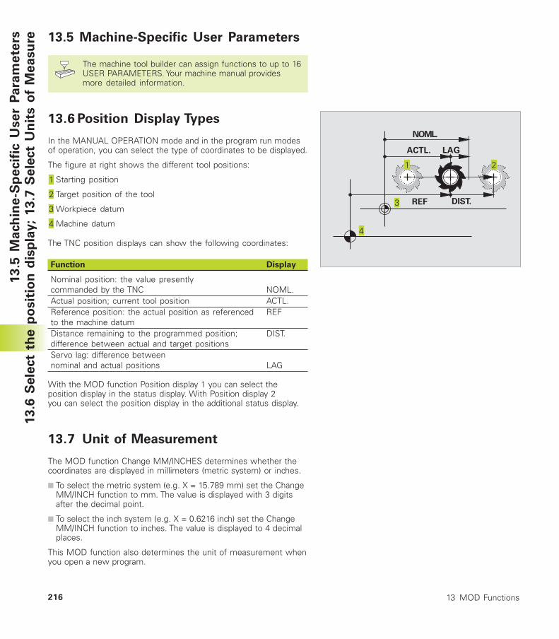
13 MOD Functions216
13
.5 M
ach
ine
-Sp
ecif
ic U
se
r P
ara
me
ters
13.6
Sele
ct
the p
osit
ion
dis
pla
y;
13.7
Sele
ct
Un
its o
f M
easu
re 13.5 Machine-Specific User Parameters
The machine tool builder can assign functions to up to 16USER PARAMETERS. Your machine manual providesmore detailed information.
13.6 Position Display Types
In the MANUAL OPERATION mode and in the program run modesof operation, you can select the type of coordinates to be displayed.
The figure at right shows the different tool positions:
Starting position
Target position of the tool
Workpiece datum
Machine datum
The TNC position displays can show the following coordinates:
Function Display
Nominal position: the value presentlycommanded by the TNC NOML.Actual position; current tool position ACTL.Reference position: the actual position as referenced REFto the machine datumDistance remaining to the programmed position; DIST.difference between actual and target positionsServo lag: difference betweennominal and actual positions LAG
With the MOD function Position display 1 you can select theposition display in the status display. With Position display 2you can select the position display in the additional status display.
13.7 Unit of Measurement
The MOD function Change MM/INCHES determines whether thecoordinates are displayed in millimeters (metric system) or inches.
■ To select the metric system (e.g. X = 15.789 mm) set the ChangeMM/INCH function to mm. The value is displayed with 3 digitsafter the decimal point.
■ To select the inch system (e.g. X = 0.6216 inch) set the ChangeMM/INCH function to inches. The value is displayed to 4 decimalplaces.
This MOD function also determines the unit of measurement whenyou open a new program.
NOML.
ACTL. LAG
REF DIST.
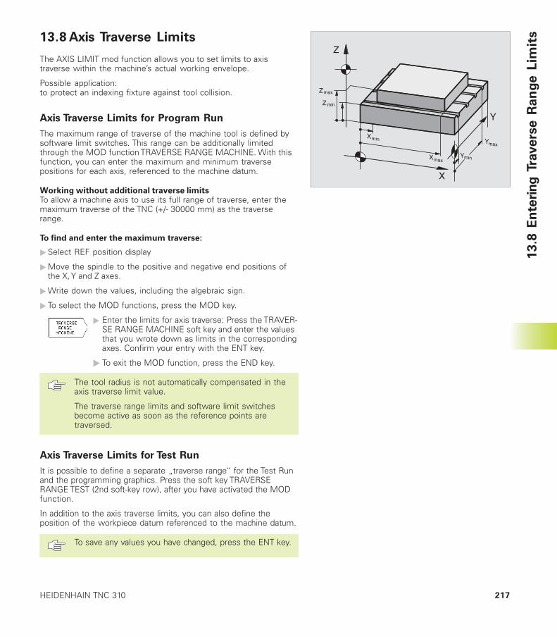
217HEIDENHAIN TNC 310
13.8 Axis Traverse Limits
The AXIS LIMIT mod function allows you to set limits to axistraverse within the machine’s actual working envelope.
Possible application:to protect an indexing fixture against tool collision.
Axis Traverse Limits for Program Run
The maximum range of traverse of the machine tool is defined bysoftware limit switches. This range can be additionally limitedthrough the MOD function TRAVERSE RANGE MACHINE. With thisfunction, you can enter the maximum and minimum traversepositions for each axis, referenced to the machine datum.
Working without additional traverse limitsTo allow a machine axis to use its full range of traverse, enter themaximum traverse of the TNC (+/- 30000 mm) as the traverserange.
To find and enter the maximum traverse:
�Select REF position display
�Move the spindle to the positive and negative end positions ofthe X, Y and Z axes.
�Write down the values, including the algebraic sign.
� To select the MOD functions, press the MOD key.
� Enter the limits for axis traverse: Press the TRAVER-SE RANGE MACHINE soft key and enter the valuesthat you wrote down as limits in the correspondingaxes. Confirm your entry with the ENT key.
� To exit the MOD function, press the END key.
The tool radius is not automatically compensated in theaxis traverse limit value.
The traverse range limits and software limit switchesbecome active as soon as the reference points aretraversed.
Axis Traverse Limits for Test Run
It is possible to define a separate „traverse range“ for the Test Runand the programming graphics. Press the soft key TRAVERSERANGE TEST (2nd soft-key row), after you have activated the MODfunction.
In addition to the axis traverse limits, you can also define theposition of the workpiece datum referenced to the machine datum.
To save any values you have changed, press the ENT key.1
3.8
En
teri
ng
Tra
ve
rse
Ra
ng
e L
imit
s
Z
Y
X
Zmin
Zmax
Xmin Ymax
YminXmax
13 MOD Functions218
13.9 Running the HELP File
The HELP function is not available on every machine.Refer to your machine tool builder for more information.
The HELP function can aid you in situations in which you need clearinstructions before you can continue (for example, to retract thetool after an interruption of power). The miscellaneous functionsmay also be explained and executed in a help file.
Selecting and executing a HELP function�Select the MOD function: Press the MOD key
�To select the HELP function: Press the HELP soft key.
�Use the up and down arrow keys to select a line in the HELP file,which is marked with an #
�Use the NC start key to execute the selected HELP function13.9
Ru
nn
ing
th
e H
ELP
File
Tables and Overviews
14
14 Tables and Overviews220
14
.1 G
en
era
l U
se
r P
ara
me
ters 14.1 General User Parameters
General user parameters are machine parameters affectingTNC settings that the user may want to change inaccordance with his requirements.
Some examples of user parameters are:
■ Dialog language
■ Interface behavior
■ Traversing speeds
■ Sequence of machining
■ Effect of overrides
Input possibilities for machine parameters
Enter the machine parameters as decimal numbers
Some machine parameters have more than one function.The input value for these machine parameters is the sum ofthe individual values. For these machine parameters theindividual values are preceded by a plus sign.
Selecting general user parameters
General user parameters are selected with code number123 in the MOD functions.
The MOD functions also include machine-specific user parameters.
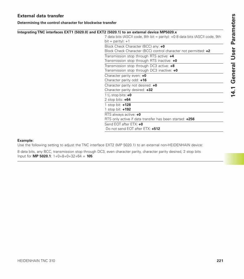
221HEIDENHAIN TNC 310
14
.1 G
en
era
l U
se
r P
ara
me
tersExternal data transfer
Determining the control character for blockwise transfer
Integrating TNC interfaces EXT1 (5020.0) and EXT2 (5020.1) to an external device MP5020.x
7 data bits (ASCII code, 8th bit = parity): +0 8 data bits (ASCII code, 9thbit = parity): +1Block Check Character (BCC) any: +0
Block Check Character (BCC) control character not permitted: +2
Transmission stop through RTS active: +4
Transmission stop through RTS inactive: +0
Transmission stop through DC3 active: +8
Transmission stop through DC3 inactive: +0
Character parity even: +0
Character parity odd: +16
Character parity not desired: +0
Character parity desired: +32
11/2 stop bits: +0
2 stop bits: +64
1 stop bit: +128
1 stop bit: +192
RTS always active: +0
RTS only active if data transfer has been started: +256
Send EOT after ETX: +0
Do not send EOT after ETX: +512
��������Use the following setting to adjust the TNC interface EXT2 (MP 5020.1) to an external non-HEIDENHAIN device:
8 data bits, any BCC, transmission stop through DC3, even character parity, character parity desired, 2 stop bitsInput for MP 5020.1: 1+0+8+0+32+64 = 105
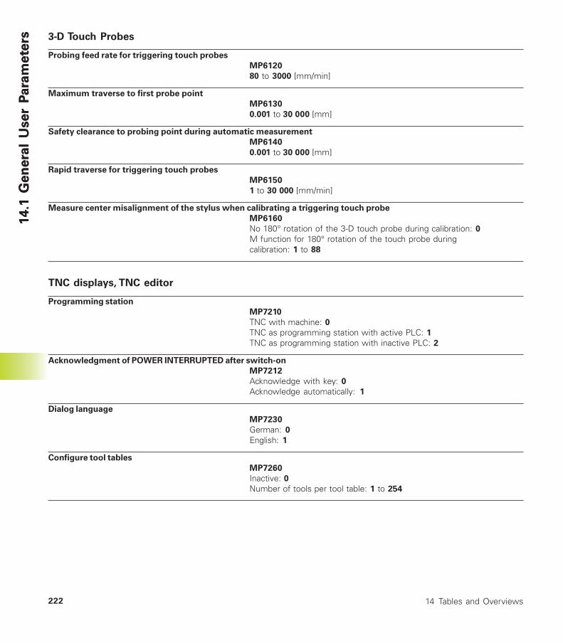
14 Tables and Overviews222
14
.1 G
en
era
l U
se
r P
ara
me
ters
14
.1 G
en
era
l U
se
r P
ara
me
ters 3-D Touch Probes
Probing feed rate for triggering touch probes
MP6120
8 to 3000 [mm/min]
Maximum traverse to first probe point
MP6130
0.001 to 30 000 [mm]
Safety clearance to probing point during automatic measurement
MP6140
0.001 to 30 000 [mm]
Rapid traverse for triggering touch probes
MP6150
1 to 30 000 [mm/min]
Measure center misalignment of the stylus when calibrating a triggering touch probe
MP6160
No 180° rotation of the 3-D touch probe during calibration: 0M function for 180° rotation of the touch probe duringcalibration: 1 to 88
TNC displays, TNC editor
Programming station
MP7210
TNC with machine: 0TNC as programming station with active PLC: 1TNC as programming station with inactive PLC: 2
Acknowledgment of POWER INTERRUPTED after switch-on
MP7212
Acknowledge with key: 0
Acknowledge automatically: 1
Dialog language
MP7230
German: 0
English: 1
Configure tool tables
MP7260
Inactive: 0Number of tools per tool table: 1 to 254
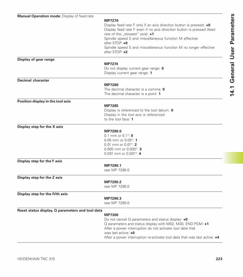
223HEIDENHAIN TNC 310
14
.1 G
en
era
l U
se
r P
ara
me
tersManual Operation mode: Display of feed rate
MP7270
Display feed rate F only if an axis direction button is pressed: +0
Display feed rate F even if no axis direction button is pressed (feedrate of the „slowest“ axis): +1
Spindle speed S and miscellaneous function M effectiveafter STOP: +0
Spindle speed S and miscellaneous function M no longer effectiveafter STOP: +2
Display of gear range
MP7274
Do not display current gear range: 0Display current gear range: 1
Decimal character
MP7280
The decimal character is a comma: 0The decimal character is a point: 1
Position display in the tool axis
MP7285
Display is referenced to the tool datum: 0Display in the tool axis is referencedto the tool face: 1
Display step for the X axis
MP7290.0
0.1 mm or 0.1°: 00.05 mm or 0.05°: 10.01 mm or 0.01°: 20.005 mm or 0.005°: 30.001 mm or 0.001°: 4
Display step for the Y axis
MP7290.1
see MP 7290.0
Display step for the Z axis
MP7290.2
see MP 7290.0
Display step for the IVth axis
MP7290.3
see MP 7290.0
Reset status display, Q parameters and tool data
MP7300
Do not cancel Q parameters and status display: +0
Q parameters and status display with M02, M30, END PGM: +1
After a power interruption do not activate tool data thatwas last active: +0
After a power interruption re-activate tool data that was last active: +4
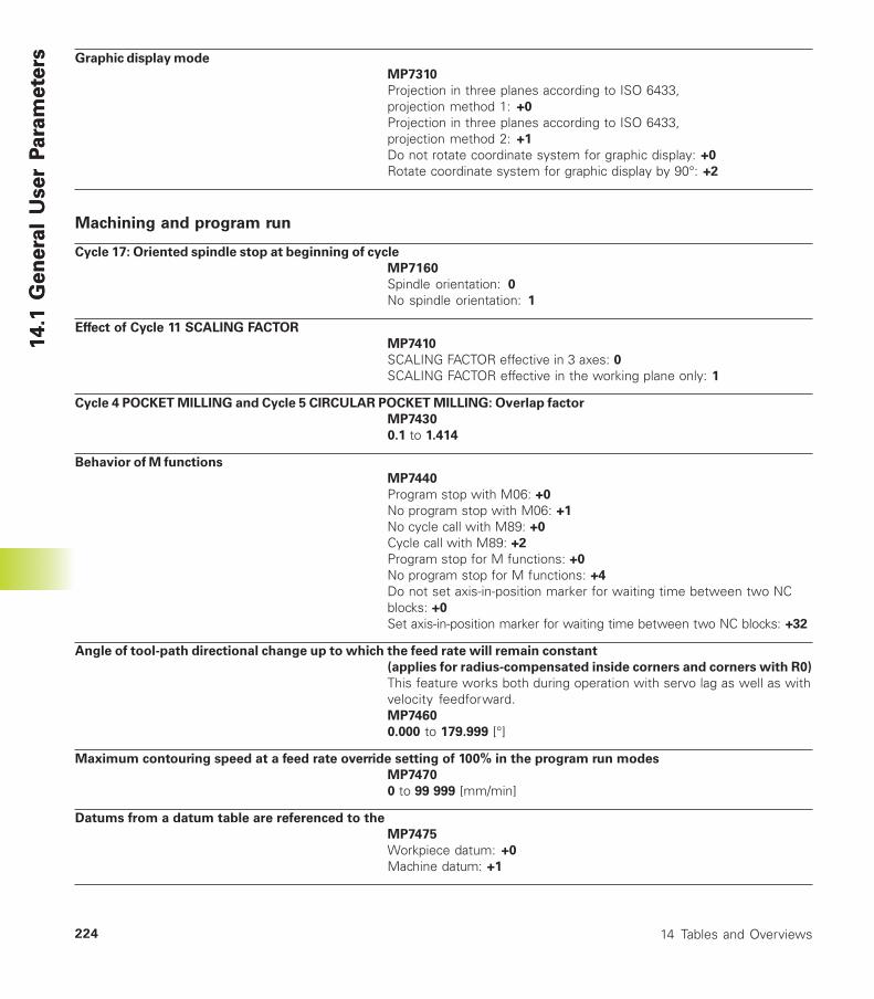
14 Tables and Overviews224
14
.1 G
en
era
l U
se
r P
ara
me
ters
14
.1 G
en
era
l U
se
r P
ara
me
ters Graphic display mode
MP7310
Projection in three planes according to ISO 6433,projection method 1: +0
Projection in three planes according to ISO 6433,projection method 2: +1
Do not rotate coordinate system for graphic display: +0
Rotate coordinate system for graphic display by 90°: +2
Machining and program run
Cycle 17: Oriented spindle stop at beginning of cycle
MP7160
Spindle orientation: 0
No spindle orientation: 1
Effect of Cycle 11 SCALING FACTOR
MP7410
SCALING FACTOR effective in 3 axes: 0SCALING FACTOR effective in the working plane only: 1
Cycle 4 POCKET MILLING and Cycle 5 CIRCULAR POCKET MILLING: Overlap factor
MP7430
0.1 to 1.414
Behavior of M functions
MP7440
Program stop with M06: +0
No program stop with M06: +1
No cycle call with M89: +0
Cycle call with M89: +2
Program stop for M functions: +0
No program stop for M functions: +4
Do not set axis-in-position marker for waiting time between two NCblocks: +0
Set axis-in-position marker for waiting time between two NC blocks: +32
Angle of tool-path directional change up to which the feed rate will remain constant
(applies for radius-compensated inside corners and corners with R0)
This feature works both during operation with servo lag as well as withvelocity feedforward.MP7460
0.000 to 179.999 [°]
Maximum contouring speed at a feed rate override setting of 100% in the program run modes
MP7470
0 to 99 999 [mm/min]
Datums from a datum table are referenced to the
MP7475
Workpiece datum: +0
Machine datum: +1
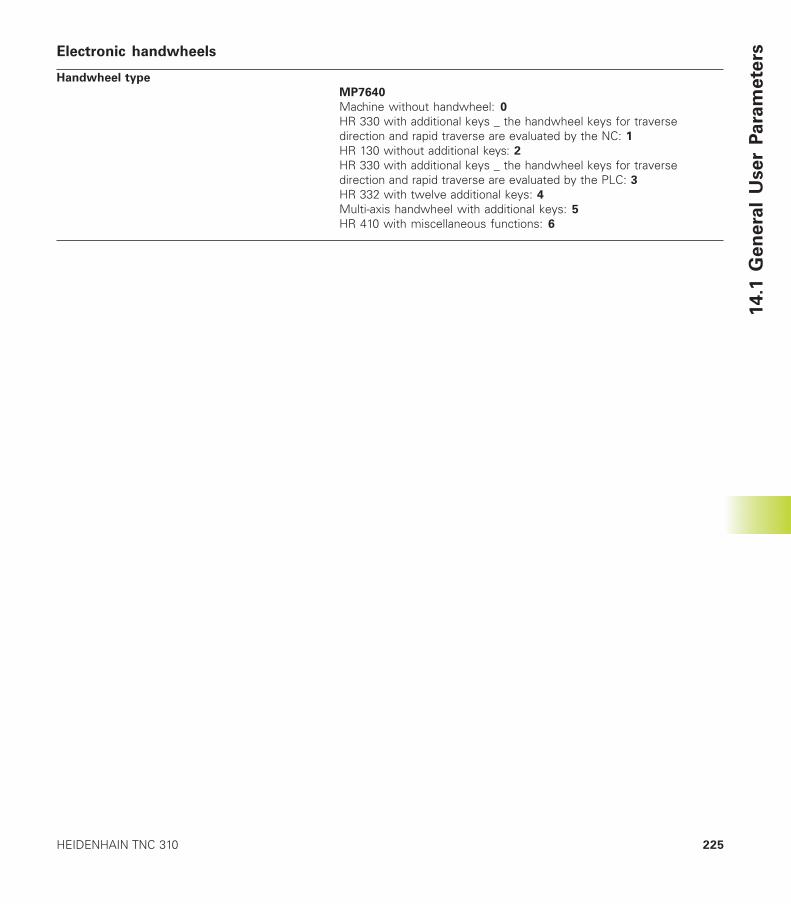
225HEIDENHAIN TNC 310
Electronic handwheels
Handwheel type
MP7640
Machine without handwheel: 0
HR 330 with additional keys _ the handwheel keys for traversedirection and rapid traverse are evaluated by the NC: 1HR 130 without additional keys: 2HR 330 with additional keys _ the handwheel keys for traversedirection and rapid traverse are evaluated by the PLC: 3HR 332 with twelve additional keys: 4Multi-axis handwheel with additional keys: 5
HR 410 with miscellaneous functions: 6
14
.1 G
en
era
l U
se
r P
ara
me
ters

14 Tables and Overviews226
14.2
P
in L
ayo
ut
an
d C
on
necti
ng
Cab
le f
or
the D
ata
In
terf
ace 14.2 Pin Layout and Connecting Cable
for the Data Interface
RS-232-C/V.24 Interface
HEIDENHAIN devices
The connector pin layout on the adapter block differsfrom that on the TNC logic unit (X21).
Non-HEIDENHAIN devicesThe connector pin layout of a non-HEIDENHAIN device may differconsiderably from that of a HEIDENHAIN device.
This often depends on the unit and type of data transfer. The figureabove shows the connector pin layout on the adapter block.
HEIDENHAIN devices
Externaldevicee.g. FE
HEIDENHAINstandard cable
3 m
RS-422 Adapterblock
HEIDENHAINconnecting cable
max. 17 m
X21TNC
Id.-Nr. 274 545 01 Id.-Nr. 286 998 ..Id.-Nr. 239 758 01
TXDRXDDSRGNDDTRCTSRTS
Transmit DataReceive DataData Set ReadySignal GroundData Terminal ReadyClear To SendRequest To Send
123456789
123456789
gegnrsgrbrrt
bl
YLGNPKGYBNRD
BL
ws/brWH/BN
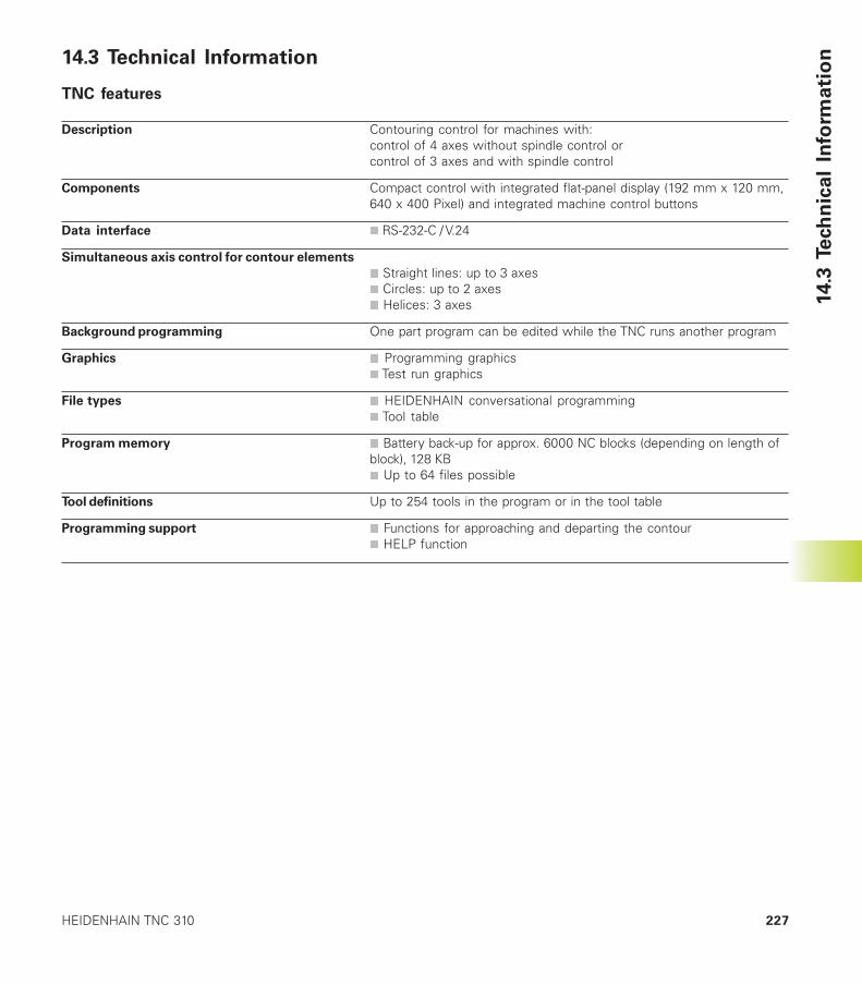
227HEIDENHAIN TNC 310
14.3
Te
ch
nic
al
Info
rma
tio
n14.3 Technical Information
TNC features
Description Contouring control for machines with:control of 4 axes without spindle control orcontrol of 3 axes and with spindle control
Components Compact control with integrated flat-panel display (192 mm x 120 mm,640 x 400 Pixel) and integrated machine control buttons
Data interface n RS-232-C / V.24
Simultaneous axis control for contour elements
n Straight lines: up to 3 axesn Circles: up to 2 axesn Helices: 3 axes
Background programming One part program can be edited while the TNC runs another program
Graphics n Programming graphicsn Test run graphics
File types n HEIDENHAIN conversational programmingn Tool table
Program memory n Battery back-up for approx. 6000 NC blocks (depending on length ofblock), 128 KBn Up to 64 files possible
Tool definitions Up to 254 tools in the program or in the tool table
Programming support n Functions for approaching and departing the contourn HELP function
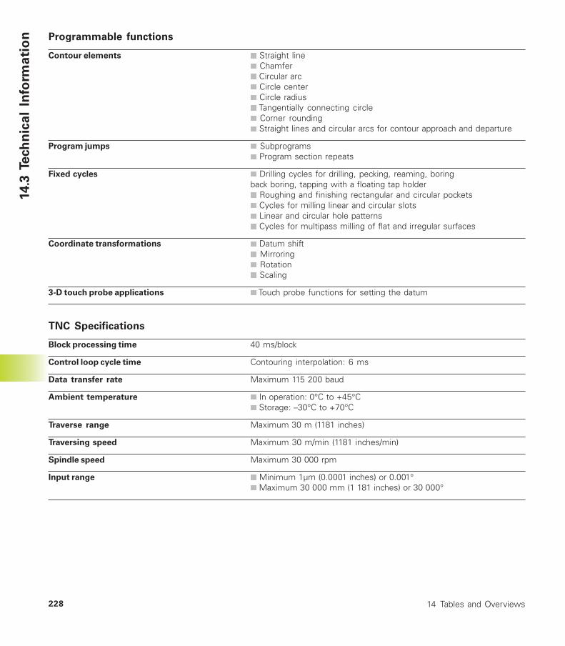
14 Tables and Overviews228
14.3
Te
ch
nic
al
Info
rma
tio
n Programmable functions
Contour elements n Straight linenÿ Chamfern Circular arcn Circle centern Circle radiusn Tangentially connecting circlen Corner roundingn Straight lines and circular arcs for contour approach and departure
Program jumps n Subprogramsn Program section repeats
Fixed cycles n Drilling cycles for drilling, pecking, reaming, boringback boring, tapping with a floating tap holdern Roughing and finishing rectangular and circular pocketsnÿCycles for milling linear and circular slotsn Linear and circular hole patternsn Cycles for multipass milling of flat and irregular surfaces
Coordinate transformations n Datum shiftn Mirroringnÿ Rotationn Scaling
3-D touch probe applications n Touch probe functions for setting the datum
TNC Specifications
Block processing time 40 ms/block
Control loop cycle time Contouring interpolation: 6 ms
Data transfer rate Maximum 115 200 baud
Ambient temperature n In operation: 0°C to +45°Cn Storage: –30°C to +70°C
Traverse range Maximum 30 m (1181 inches)
Traversing speed Maximum 30 m/min (1181 inches/min)
Spindle speed Maximum 30 000 rpm
Input range n Minimum 1µm (0.0001 inches) or 0.001°n Maximum 30 000 mm (1 181 inches) or 30 000°

229HEIDENHAIN TNC 310
14.4
TN
C E
rro
r M
essa
ge
s14.4 TNC Error Messages
The TNC automatically generates error messages when it detectsproblems such as
■ Incorrect data input■ Logical errors in the program■ Contour elements that are impossible to machine■ Incorrect use of the touch probe system
Some of the more frequent TNC error messages are explained in the following list.
An error message that contains a program block number was caused by an error in the indicated block or in the precedingblock. To clear the TNC error message, first correct the error and then press the CE key.
TNC error messages during programming
Further program entry impossible Erase some old files to make room for new ones.
Entry value incorrect n Enter a correct label numbern Note the input limits
Ext. in-/output not ready n Connect the data transfer cable.n Transfer cable is defective or not soldered properly.n Switch on the connected device (PC, printer).n The data transfer speeds (baud rates) are not identical.
Protected file! Cancel edit protection if you wish to edit the file.
Label number already assigned A given label number can only be entered once in a program.
Jump to label 0 not permitted Do not program CALL LBL 0.
TNC error messages during test run and program run
Axis double programmed Each axis can have only one value for position coordinates.
Selected block not addressed Before a test run or program run, you must enter GOTO 0.
Touch point inaccessible n Pre-position the 3-D touch probe to a position nearer the model
Arithmetical error You have calculated with non-permissible valuesn Define values within the range limitsn Choose probe positions for the 3-D touch probe that are farther apart
Path offset wrongly ended Do not cancel tool radius compensation in a block with a circularpath
Path offset wrongly started n Use the same radius compensation before and after an RND andCHF block.nÿDo not begin tool radius compensation in a block with a circularpath.
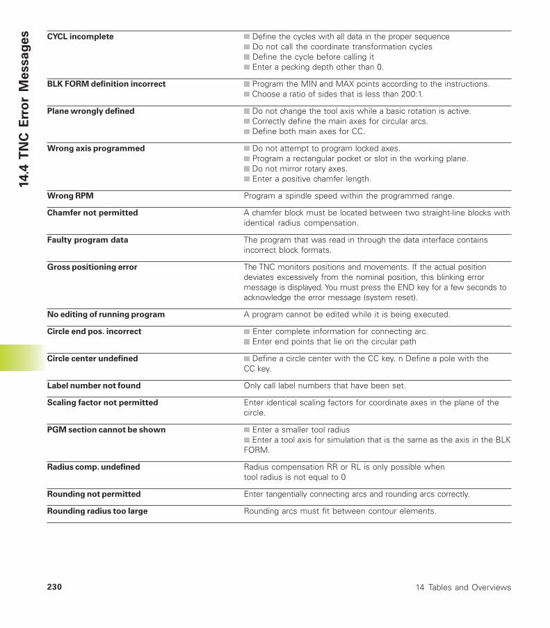
14 Tables and Overviews230
14.4
TN
C E
rro
r M
essa
ge
s CYCL incomplete n Define the cycles with all data in the proper sequencen Do not call the coordinate transformation cyclesn Define the cycle before calling itn Enter a pecking depth other than 0.
BLK FORM definition incorrect n Program the MIN and MAX points according to the instructions.n Choose a ratio of sides that is less than 200:1.
Plane wrongly defined n Do not change the tool axis while a basic rotation is active.n Correctly define the main axes for circular arcs.n Define both main axes for CC.
Wrong axis programmed n Do not attempt to program locked axes.n Program a rectangular pocket or slot in the working plane.n Do not mirror rotary axes.n Enter a positive chamfer length.
Wrong RPM Program a spindle speed within the programmed range.
Chamfer not permitted A chamfer block must be located between two straight-line blocks withidentical radius compensation.
Faulty program data The program that was read in through the data interface containsincorrect block formats.
Gross positioning error The TNC monitors positions and movements. If the actual positiondeviates excessively from the nominal position, this blinking errormessage is displayed. You must press the END key for a few seconds toacknowledge the error message (system reset).
No editing of running program A program cannot be edited while it is being executed.
Circle end pos. incorrect n Enter complete information for connecting arc.n Enter end points that lie on the circular path
Circle center undefined n Define a circle center with the CC key. n Define a pole with theCC key.
Label number not found Only call label numbers that have been set.
Scaling factor not permitted Enter identical scaling factors for coordinate axes in the plane of thecircle.
PGM section cannot be shown n Enter a smaller tool radiusn Enter a tool axis for simulation that is the same as the axis in the BLKFORM.
Radius comp. undefined Radius compensation RR or RL is only possible whentool radius is not equal to 0
Rounding not permitted Enter tangentially connecting arcs and rounding arcs correctly.
Rounding radius too large Rounding arcs must fit between contour elements.
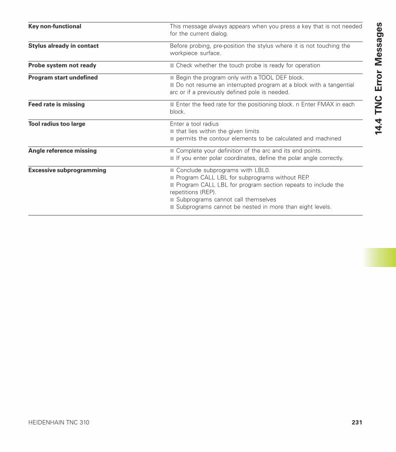
231HEIDENHAIN TNC 310
14.4
TN
C E
rro
r M
essa
ge
sKey non-functional This message always appears when you press a key that is not neededfor the current dialog.
Stylus already in contact Before probing, pre-position the stylus where it is not touching theworkpiece surface.
Probe system not ready n Check whether the touch probe is ready for operation
Program start undefined n Begin the program only with a TOOL DEF block.n Do not resume an interrupted program at a block with a tangentialarc or if a previously defined pole is needed.
Feed rate is missing n Enter the feed rate for the positioning block. n Enter FMAX in eachblock.
Tool radius too large Enter a tool radiusn that lies within the given limitsn permits the contour elements to be calculated and machined
Angle reference missing n Complete your definition of the arc and its end points.n If you enter polar coordinates, define the polar angle correctly.
Excessive subprogramming n Conclude subprograms with LBL0.n Program CALL LBL for subprograms without REP.n Program CALL LBL for program section repeats to include therepetitions (REP).n Subprograms cannot call themselvesn Subprograms cannot be nested in more than eight levels.
14 Tables and Overviews232
14.5 Exchanging the Buffer Battery
A buffer battery supplies the TNC with current to prevent the data inRAM memory from being lost when the TNC is switched off.
If the TNC displays the error message Exchange buffer battery, thenyou must replace the batteries. The batteries are located in thecontrol housing (refer also to your Machine Manual). The TNC alsohas an power storage device that provide the control with currentwhile you are exchanging the batteries (for a maximum of24 hours).
To exchange the buffer battery, first switch off the TNC!
The buffer battery must be exchanged only by trainedservice personnel!
Battery type: Three AA-size cells, leak-proof, IEC designation „LR6“
14
.5 E
xch
an
gin
g t
he
Bu
ffe
r B
att
ery
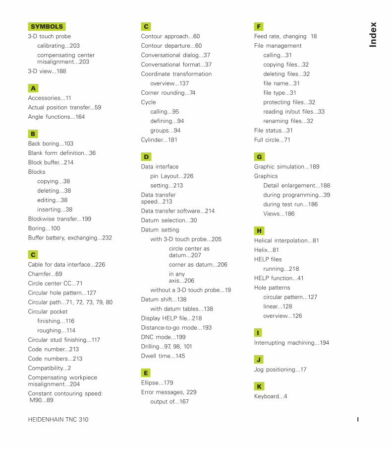
Ind
ex
IHEIDENHAIN TNC 310
SYMBOLS
3-D touch probe
calibrating...203
compensating centermisalignment...203
3-D view...188
A
Accessories...11
Actual position transfer...59
Angle functions...164
B
Back boring...103
Blank form definition...36
Block buffer...214
Blocks
copying...38
deleting...38
editing...38
inserting...38
Blockwise transfer...199
Boring...100
Buffer battery, exchanging...232
C
Cable for data interface...226
Chamfer...69
Circle center CC...71
Circular hole pattern...127
Circular path...71, 72, 73, 79, 80
Circular pocket
finishing...116
roughing...114
Circular stud finishing...117
Code number...213
Code numbers...213
Compatibility...2
Compensating workpiecemisalignment...204
Constant contouring speed: M90...89
C
Contour approach...60
Contour departure...60
Conversational dialog...37
Conversational format...37
Coordinate transformation
overview...137
Corner rounding...74
Cycle
calling...95
defining...94
groups...94
Cylinder...181
D
Data interface
pin Layout...226
setting...213
Data transferspeed...213
Data transfer software...214
Datum selection...30
Datum setting
with 3-D touch probe...205
circle center asdatum...207
corner as datum...206
in anyaxis...206
without a 3-D touch probe...19
Datum shift...138
with datum tables...138
Display HELP file...218
Distance-to-go mode...193
DNC mode...199
Drilling...97, 98, 101
Dwell time...145
E
Ellipse...179
Error messages, 229
output of...167
F
Feed rate, changing 18
File management
calling...31
copying files...32
deleting files...32
file name...31
file type...31
protecting files...32
reading in/out files...33
renaming files...32
File status...31
Full circle...71
G
Graphic simulation...189
Graphics
Detail enlargement...188
during programming...39
during test run...186
Views...186
H
Helical interpolation...81
Helix...81
HELP files
running...218
HELP function...41
Hole patterns
circular pattern...127
linear...128
overview...126
I
Interrupting machining...194
J
Jog positioning...17
K
Keyboard...4
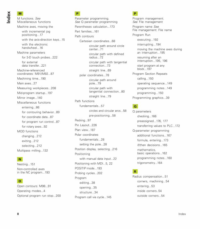
Ind
ex
IndexII
M
M functions. SeeMiscellaneous functions
Machine axes, moving the
with incremental jogpositioning...17
with the axis-direction keys...15
with the electronichandwheel...16
Machine parameters
for 3-D touch probes...222
for externaldata transfer...221
Machine-referencedcoordinates: M91/M92...87
Machining time...190
Main axes...27
Measuring workpieces...208
Mid-program startup...197
Mirror image...140
Miscellaneous functions
entering...86
for contouring behavior...89
for coordinate data...87
for program run control...87
for rotary axes...92
MOD functions
changing...212
exiting...212
selecting...212
Multipass milling...132
N
Nesting...151
Non-controlled axesin the NC program...193
O
Open contours: M98...91
Operating modes...4
Optional program run stop...200
P
Parameter programming.See Q parameter programming
Parentheses calculation...173
Part families...161
Path contours
Cartesian coordinates...68
circular path around circlecenter...71
circular path with definedradius...72
circular path with tangentialconnection...73
straight line...69
polar coordinates...78
circular path aroundpole...79
circular path withtangential connection...80
straight line...79
Path functions
fundamentals...57
circles and circular arcs...58
pre-positioning...58
Pecking...97
Pin Layout...226
Plan view...187
Polar coordinates
fundamentals...28
setting the pole...28
Position display, selecting...216
Positioning
with manual data input...22
Positioning with MDI...5, 22
POSITIP mode...193
Probing cycles...202
Program
editing...38
opening...35
structure...34
Program call via cycle...145
P
Program management.See File management
Program name SeeFile management: File name
Program Run
executing...192
interrupting...194
moving the machine axes duringan interruption...195
resuming after aninterruption...195, 196
start program at anyblock...197
Program Section Repeats
calling...150
operating sequence...149
programming notes...149
programming...150
Programming graphics...39
Q
Q parameters
checking...166
preassigned...176, 177
transferring values to PLC...172
Q-parameter programming
additional functions...167
formula, entering...173
if/then decisions...165
mathematics,basic operations...162
programming notes...160
trigonometry...164
R
Radius compensation...51
corners, machining...54
entering...53
inside corners..54
outside corners...54
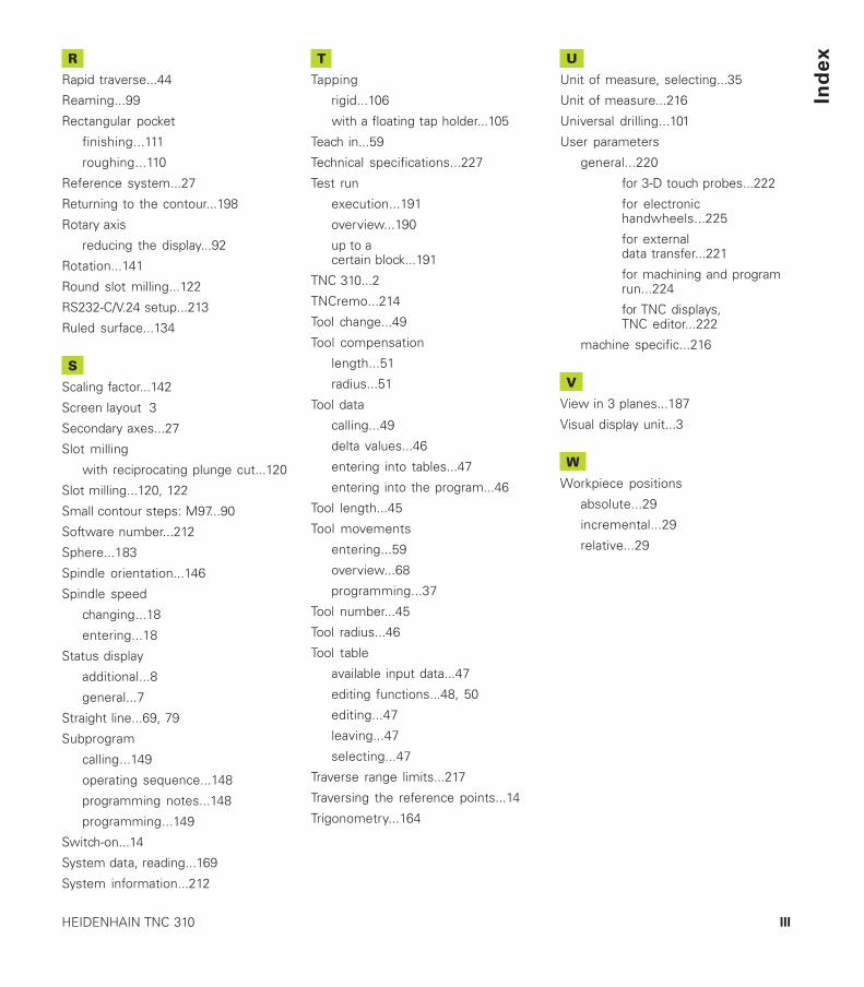
Ind
ex
IIIHEIDENHAIN TNC 310
R
Rapid traverse...44
Reaming...99
Rectangular pocket
finishing...111
roughing...110
Reference system...27
Returning to the contour...198
Rotary axis
reducing the display...92
Rotation...141
Round slot milling...122
RS232-C/V.24 setup...213
Ruled surface...134
S
Scaling factor...142
Screen layout 3
Secondary axes...27
Slot milling
with reciprocating plunge cut...120
Slot milling...120, 122
Small contour steps: M97...90
Software number...212
Sphere...183
Spindle orientation...146
Spindle speed
changing...18
entering...18
Status display
additional...8
general...7
Straight line...69, 79
Subprogram
calling...149
operating sequence...148
programming notes...148
programming...149
Switch-on...14
System data, reading...169
System information...212
T
Tapping
rigid...106
with a floating tap holder...105
Teach in...59
Technical specifications...227
Test run
execution...191
overview...190
up to acertain block...191
TNC 310...2
TNCremo...214
Tool change...49
Tool compensation
length...51
radius...51
Tool data
calling...49
delta values...46
entering into tables...47
entering into the program...46
Tool length...45
Tool movements
entering...59
overview...68
programming...37
Tool number...45
Tool radius...46
Tool table
available input data...47
editing functions...48, 50
editing...47
leaving...47
selecting...47
Traverse range limits...217
Traversing the reference points...14
Trigonometry...164
U
Unit of measure, selecting...35
Unit of measure...216
Universal drilling...101
User parameters
general...220
for 3-D touch probes...222
for electronichandwheels...225
for externaldata transfer...221
for machining and programrun...224
for TNC displays,TNC editor...222
machine specific...216
V
View in 3 planes...187
Visual display unit...3
W
Workpiece positions
absolute...29
incremental...29
relative...29

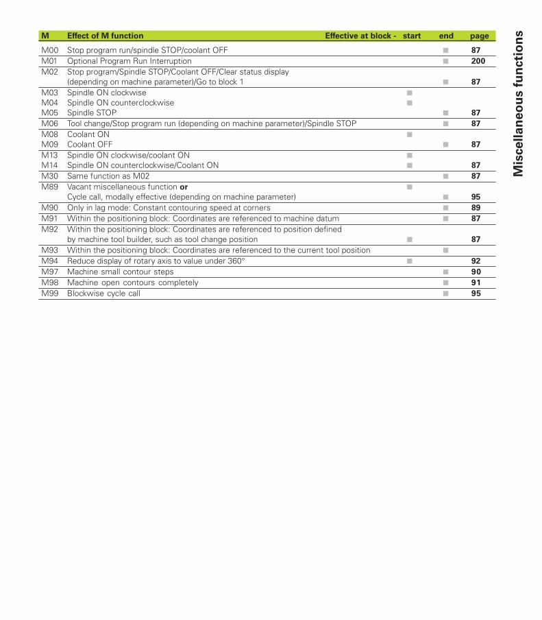
M Effect of M function Effective at block - start end page
M00 Stop program run/spindle STOP/coolant OFF ■ 87
M01 Optional Program Run Interruption ■ 200
M02 Stop program/Spindle STOP/Coolant OFF/Clear status display(depending on machine parameter)/Go to block 1 ■ 87
M03 Spindle ON clockwise ■
M04 Spindle ON counterclockwise ■
M05 Spindle STOP ■ 87
M06 Tool change/Stop program run (depending on machine parameter)/Spindle STOP ■ 87
M08 Coolant ON ■
M09 Coolant OFF ■ 87
M13 Spindle ON clockwise/coolant ON ■
M14 Spindle ON counterclockwise/Coolant ON ■ 87
M30 Same function as M02 ■ 87
M89 Vacant miscellaneous function or ■
Cycle call, modally effective (depending on machine parameter) ■ 95
M90 Only in lag mode: Constant contouring speed at corners ■ 89
M91 Within the positioning block: Coordinates are referenced to machine datum ■ 87
M92 Within the positioning block: Coordinates are referenced to position definedby machine tool builder, such as tool change position ■ 87
M93 Within the positioning block: Coordinates are referenced to the current tool position ■
M94 Reduce display of rotary axis to value under 360° ■ 92
M97 Machine small contour steps ■ 90
M98 Machine open contours completely ■ 91
M99 Blockwise cycle call ■ 95
Mis
cellan
eo
us f
un
cti
on
s

Ve 00331 645-22 · 4/2003 · pdf · Subject to change without notice
������������ ��� ��������������� ��������������������������������������� ���������������� ����������������� �!"��#�$����������
����� ��!�"�##$�� � �������������������� �!"����%�&�$����������
%��"�� �&�"�"���" � �������������������� �!"����%�&��'���())���$����������
�'�"�##$�� � �������������������� �!"����%�&��&��())���$����������
'�#�$&���� �& � �������������������� �!"����%�&��&�)*'$����������
()'�#�$&���� �& � �����������������+�� �!"����%�&��)!&$����������
)������$���$!" � �����,������+������� �!"����%�&����#$����������
***��� +���� ��+�