Embed Size (px)
DESCRIPTION
Atlas capco
Citation preview
www.atlascopco.com
Atlas Copco Instruction Manual
XAMS 407 Cd - XAMS 850 CD7XATS 377 Cd - XATS 800 CD7 Engine CAT C7XAHS 347 Cd - XAHS 710 CD7XAVS 307 Cd - XAVS 650 CD7
Instruction Manualfor Portable CompressorsEnglish

ATLAS COPCO - PORTABLE AIR DIVISIONwww.atlascopco.com
Printed matter N°2954 3190 01
05/2008
Instruction Manualfor Portable Compressors
XAMS 407 Cd - XAMS 850 CD7XATS 377 Cd - XATS 800 CD7XAHS 347 Cd - XAHS 710 CD7XAVS 307 Cd - XAVS 650 CD7
Warranty and Liability LimitationUse only authorized parts.Any damage or malfunction caused by the use of unauthorized parts is not covered by Warranty or ProductLiability.The manufacturer does not accept any liability for any damage arising for modifications, additions orconversions made without the manufacturer's approval in writing.While every effort has been made to ensure that the information in this manual is correct, Atlas Copco does notassume responsibility for possible errors.
Copyright 2008, Atlas Copco Airpower n.v., Antwerp, Belgium.Any unauthorized use or copying of the contents or any part thereof is prohibited.This applies in particular to trademarks, model denominations, part numbers and drawings.
- 2 -
PrefacePlease read the following instructions carefullybefore starting to use your compressor.It is a solid, safe and reliable machine, builtaccording to the latest technology. Follow theinstructions in this booklet and we guarantee youyears of troublefree operation.Always keep the manual available near the machine.In all correspondence always mention thecompressor type and serial number, shown on thedata plate.The company reserves the right to make changeswithout prior notice.
Table of contents1 Safety precautions ...................................... 51.1 Introduction .................................................. 51.2 General safety precautions ........................... 61.3 Safety during transport and installation ....... 71.4 Safety during use and operation................... 71.5 Safety during maintenance and repair.......... 91.6 Tool applications safety ............................. 101.7 Specific safety precautions......................... 11
2 Leading particulars .................................. 122.1 General description .................................... 12
3 Main Parts................................................. 143.1 Compressor regulating system ................... 163.1.1 Overview................................................ 163.1.2 Air flow.................................................. 183.1.3 Oil system .............................................. 193.1.4 Continuous regulating system................ 203.2 Electric system ........................................... 223.3 Markings and information labels ............... 26
4 Operating instructions ............................. 274.1 Parking, towing and lifting instructions ..... 274.1.1 Parking instructions ............................... 274.1.2 Towing instructions ............................... 284.1.3 Height adjustment .................................. 294.1.4 Lifting instructions................................. 294.2 Starting / Stopping...................................... 304.3 Before starting ............................................ 304.3.1 Battery switch ........................................ 314.3.2 Control panel.......................................... 324.3.3 Xc2002™ module .................................. 32
4.3.4 Xc2002™ Menu Overview.................... 334.3.5 Xc2002™ Menu Description................. 374.3.6 During operation .................................... 394.3.7 Operations overview.............................. 394.3.8 Power ON / OFF.................................... 404.3.9 Starting................................................... 404.3.10 Warming up ........................................... 404.3.11 Loading .................................................. 404.3.12 Stopping................................................. 414.3.13 Emergency stop ..................................... 414.3.14 Fault codes ............................................. 42
5 Maintenance ............................................. 435.1 Liability...................................................... 435.2 Service paks ............................................... 435.3 Service kits................................................. 435.4 Storage ....................................................... 435.5 Preventive maintenance schedule
for the compressor...................................... 445.6 Oil specifications........................................ 475.6.1 Compressor oil....................................... 475.6.2 Engine oil............................................... 485.7 Oil level check ........................................... 495.7.1 Check engine oil level ........................... 495.7.2 Check compressor oil level.................... 495.8 Oil and oil filter change ............................. 505.8.1 Engine oil and oil filter change.............. 505.8.2 Compressor oil and oil filter change...... 505.8.3 Topping up the compressor oil .............. 515.9 Coolant specifications ................................ 515.9.1 PARCOOL EG ...................................... 525.9.2 Handling PARCOOL EG ...................... 535.10 Coolant check............................................. 535.11 Topping up/replacing coolant .................... 53
- 3 -
5.11.1 Topping up without draining from the cooling system......................... 54
5.11.2 Topping up after limited quantity draining from the cooling system........... 55
5.11.3 Replacing the coolant............................. 565.11.4 Cleaning coolers..................................... 565.12 Battery care................................................. 575.12.1 Electrolyte .............................................. 575.12.2 Activating a dry-charged battery............ 575.12.3 Recharging a battery .............................. 575.12.4 Battery maintenance............................... 575.13 Compressor element overhaul .................... 57
6 Adjustments and servicing procedures .. 586.1 Adjustment of the continuous
regulating system........................................ 586.2 Air filter engine/compressor....................... 596.2.1 Servicing ................................................ 596.2.2 Main parts .............................................. 596.2.3 Cleaning the dust trap ............................ 596.2.4 Cleaning instructions filter element ....... 596.2.5 Replacing the air filter element .............. 606.2.6 Air receiver............................................. 616.3 Safety valve ................................................ 616.4 Fuel system................................................. 616.4.1 Priming instructions ............................... 616.4.2 Draining instructions.............................. 626.5 Brake adjustment........................................ 636.5.1 Brake shoe adjustment ........................... 636.5.2 Audit procedure of
brake cable adjustment........................... 646.5.3 Brake cable adjustment .......................... 656.5.4 Test procedure of
brake cable adjustment........................... 65
7 Problem solving ........................................ 66
8 Available options ...................................... 69
9 Technical specifications ........................... 719.1 Torque values ............................................. 719.1.1 General torque values ............................ 719.1.2 Critical torque values ............................. 719.2 Compressor / engine specifications............ 729.2.1 Reference conditions.............................. 729.2.2 Limitations ............................................. 729.2.3 Altitude unit performance curve ............ 739.2.4 Altitude unit performance curve ............ 749.2.5 Performance data ................................... 759.2.6 Design data............................................. 77
10 Dataplate ................................................... 79
11 Legislation Size 2 LP ................................ 8011.1 Parts, subjected to Pressure Equipment
Directive 97/23/EC, cat. II and above........ 8011.2 Parts, subjected to Simple Pressure
Vessel Directive 87/404/EC....................... 8011.3 Parts, subjected to cat. I and covered
by the Machine Directive 89/392/EC......... 8111.4 Parts, subjected to art. I, paragraph 3.3 ...... 81
12 Disposal ..................................................... 8212.1 General ....................................................... 8212.2 Disposal of materials.................................. 82
13 Maintenance Log ...................................... 83
- 4 -
Safety precautions
INTRODUCTION
The policy of Atlas Copco is to provide the users oftheir equipment with safe, reliable and efficientproducts. Factors taken into account are amongothers:- the intended and predictable future use of the
products, and the environments in which they areexpected to operate,
- applicable rules, codes and regulations,- the expected useful product life, assuming proper
service and maintenance,- providing the manual with up-to-date
information.Before handling any product, take time to read therelevant instruction manual. Besides giving detailedoperating instructions, it also gives specificinformation about safety, preventive maintenance,etc.Keep the manual always at the unit location, easyaccessible to the operating personnel.See also the safety precautions of the engine andpossible other equipment, which are separately sentalong or are mentioned on the equipment or parts ofthe unit.These safety precautions are general and somestatements will therefore not always apply to aparticular unit.Only people that have the right skills should beallowed to operate, adjust, perform maintenance orrepair on Atlas Copco equipment.
It is the responsibility of management to appointoperators with the appropriate training and skill foreach category of job.Skill level 1: OperatorAn operator is trained in all aspects of operating theunit with the push-buttons, and is trained to know thesafety aspects.Skill level 2: Mechanical technicianA mechanical technician is trained to operate the unitthe same as the operator. In addition, the mechanicaltechnician is also trained to perform maintenance andrepair, as described in the instruction manual, and isallowed to change settings of the control and safetysystem. A mechanical technician does not work onlive electrical components.Skill level 3: Electrical technicianAn electrical technician is trained and has the samequalifications as both the operator and the mechanicaltechnician. In addition, the electrical technician maycarry out electrical repairs within the variousenclosures of the unit. This includes work on liveelectrical components.Skill level 4: Specialist from the manufacturerThis is a skilled specialist sent by the manufacturer orits agent to perform complex repairs or modificationsto the equipment.In general it is recommended that not more than twopeople operate the unit, more operators could lead tounsafe operating conditions.
Take necessary steps to keep unauthorized personsaway from the unit and eliminate all possible sourcesof danger at the unit.When handling, operating, overhauling and/orperforming maintenance or repair on Atlas Copcoequipment, the mechanics are expected to use safeengineering practices and to observe all relevant localsafety requirements and ordinances. The followinglist is a reminder of special safety directives andprecautions mainly applicable to Atlas Copcoequipment.These safety precautions apply to machineryprocessing or consuming air. Processing of any othergas requires additional safety precautions typical tothe application and are not included herein.Neglecting the safety precautions may endangerpeople as well as environment and machinery:- endanger people due to electrical, mechanical or
chemical influences,- endanger the environment due to leakage of oil,
solvents or other substances,- endanger the machinery due to function failures.All responsibility for any damage or injury resultingfrom neglecting these precautions or by non-observance of ordinary caution and due care requiredin handling, operating, maintenance or repair, also ifnot expressly mentioned in this instruction manual, isdisclaimed by Atlas Copco.
To be read attentively and acted accordingly before towing, lifting, operating, performingmaintenance or repairing the compressor.
- 5 -
The manufacturer does not accept any liability for anydamage arising from the use of non-original parts andfor modifications, additions or conversions madewithout the manufacturer’s approval in writing.If any statement in this manual does not comply withlocal legislation, the stricter of the two shall beapplied.Statements in these safety precautions should not beinterpreted as suggestions, recommendations orinducements that it should be used in violation of anyapplicable laws or regulations.
GENERAL SAFETY PRECAUTIONS
1 The owner is responsible for maintaining the unitin a safe operating condition. Unit parts andaccessories must be replaced if missing orunsuitable for safe operation.
2 The supervisor, or the responsible person, shall atall times make sure that all instructions regardingmachinery and equipment operation andmaintenance are strictly followed and that themachines with all accessories and safety devices,as well as the consuming devices, are in goodrepair, free of abnormal wear or abuse, and arenot tampered with.
3 Whenever there is an indication or any suspicionthat an internal part of a machine is overheated,the machine shall be stopped but no inspectioncovers shall be opened before sufficient coolingtime has elapsed; this to avoid the risk ofspontaneous ignition of oil vapour when air isadmitted.
4 Normal ratings (pressures, temperatures, speeds,etc.) shall be durably marked.
5 Operate the unit only for the intended purpose andwithin its rated limits (pressure, temperature,speeds, etc.).
6 The machinery and equipment shall be kept clean,i.e. as free as possible from oil, dust or otherdeposits.
7 To prevent an increase in working temperature,inspect and clean heat transfer surfaces (coolerfins, intercoolers, water jackets, etc.) regularly.See the Preventive maintenance schedule forthe compressor.
8 All regulating and safety devices shall bemaintained with due care to ensure that theyfunction properly. They may not be put out ofaction.
9 Care shall be taken to avoid damage to safetyvalves and other pressure-relief devices,especially to avoid plugging by paint, oil coke ordirt accumulation, which could interfere with thefunctioning of the device.
10 Pressure and temperature gauges shall be checkedregularly with regard to their accuracy. They shallbe replaced whenever outside acceptabletolerances.
11 Safety devices shall be tested as described in themaintenance schedule of the instruction manualto determine that they are in good operatingcondition. See the Preventive maintenanceschedule for the compressor.
12 Mind the markings and information labels on theunit.
13 In the event the safety labels are damaged ordestroyed, they must be replaced to ensureoperator safety.
14 Keep the work area neet. Lack of order willincrease the risk of accidents.
15 When working on the unit, wear safety clothing.Depending on the kind of activities these are:safety glasses, ear protection, safety helmet(including visor), safety gloves, protectiveclothing, safety shoes. Do not wear the hair longand loose (protect long hair with a hairnet), orwear loose clothing or jewelry.
16 Take precautions against fire. Handle fuel, oil andanti-freeze with care because they areinflammable substances. Do not smoke orapproach with naked flame when handling suchsubstances. Keep a fire-extinguisher in thevicinity.
- 6 -
SAFETY DURING TRANSPORT AND INSTALLATION
When towing, lifting or transporting the compressorin any way, the battery switch must always be in the“OFF” position!To lift a unit, all loose or pivoting parts, e.g. doors andtowbar, shall first be securely fastened.Do not attach cables, chains or ropes directly to thelifting eye; apply a crane hook or lifting shacklemeeting local safety regulations. Never allow sharpbends in lifting cables, chains or ropes.Helicopter lifting is not allowed.It is strictly forbidden to dwell or stay in the risk zoneunder a lifted load. Never lift the unit over people orresidential areas. Lifting acceleration and retardationshall be kept within safe limits.1 Before towing the unit:
- ascertain that the pressure vessel(s) is (are)depressurized,
- check the towbar, the brake system and thetowing eye. Also check the coupling of thetowing vehicle,
- check the towing and brake capability of thetowing vehicle,
- check that the towbar, jockey wheel or standleg is safely locked in the raised position,
- ascertain that the towing eye can swivel freelyon the hook,
- check that the wheels are secure and that thetyres are in good condition and inflatedcorrectly,
- connect the signalisation cable, check all lightsand connect the pneumatic brake couplers,
- attach the safety break-away cable or safetychain to the towing vehicle,
- remove wheel chocks, if applied, anddisengage the parking brake.
2 To tow a unit use a towing vehicle of amplecapacity. Refer to the documentation of thetowing vehicle.
3 If the unit is to be backed up by the towingvehicle, disengage the overrun brake mechanism(if it is not an automatic mechanism).
4 Never exceed the maximum towing speed of theunit (mind the local regulations).
5 Place the unit on level ground and apply theparking brake before disconnecting the unit fromthe towing vehicle. Unclip the safety break-awaycable or safety chain. If the unit has no parkingbrake or jockey wheel, immobilize the unit byplacing chocks in front of and/or behind thewheels. When the towbar can be positionedvertically, the locking device must be applied andkept in good order.
6 To lift heavy parts, a hoist of ample capacity,tested and approved according to local safetyregulations, shall be used.
7 Lifting hooks, eyes, shackles, etc., shall never bebent and shall only have stress in line with theirdesign load axis. The capacity of a lifting devicediminishes when the lifting force is applied at anangle to its load axis.
8 For maximum safety and efficiency of the liftingapparatus all lifting members shall be applied asnear to perpendicular as possible. If required, alifting beam shall be applied between hoist andload.
9 Never leave a load hanging on a hoist.10 A hoist has to be installed in such a way that the
object will be lifted perpendicular. If that is notpossible, the necessary precautions must be takento prevent load-swinging, e.g. by using two
hoists, each at approximately the same angle notexceeding 30° from the vertical.
11 Locate the unit away from walls. Take allprecautions to ensure that hot air exhausted fromthe engine and driven machine cooling systemscannot be recirculated. If such hot air is taken inby the engine or driven machine cooling fan, thismay cause overheating of the unit; if taken in forcombustion, the engine power will be reduced.
12 Before moving the compressor, switch it off.13 If the warning light on the ABS module or in the
vehicle lights up, please contact Atlas Copco.
SAFETY DURING USE AND OPERATION
1 When the unit has to operate in a fire-hazardousenvironment, each engine exhaust has to beprovided with a spark arrestor to trap incendiarysparks.
2 The exhaust contains carbon monoxide which is alethal gas. When the unit is used in a confinedspace, conduct the engine exhaust to the outsideatmosphere by a pipe of sufficient diameter; dothis in such a way that no extra back pressure iscreated for the engine. If necessary, install anextractor. Observe any existing local regulations.Make sure that the unit has sufficient air intakefor operation. If necessary, install extra air intakeducts.
3 When operating in a dust-laden atmosphere, placethe unit so that dust is not carried towards it by thewind. Operation in clean surroundingsconsiderably extends the intervals for cleaningthe air intake filters and the cores of the coolers.
- 7 -
4 Close the compressor air outlet valve beforeconnecting or disconnecting a hose. Ascertainthat a hose is fully depressurized beforedisconnecting it. Before blowing compressed airthrough a hose or air line, ensure that the open endis held securely, so that it cannot whip and causeinjury.
5 The air line end connected to the outlet valvemust be safeguarded with a safety cable, attachednext to the valve.
6 No external force may be exerted on the air outletvalves, e.g. by pulling on hoses or by installingauxiliary equipment directly to a valve, e.g. awater separator, a lubricator, etc. Do not step onthe air outlet valves.
7 Never move a unit when external lines or hosesare connected to the outlet valves, to avoiddamage to valves, manifold and hoses.
8 Do not use compressed air from any type ofcompressor, without taking extra measures, forbreathing purposes as this may result in injury ordeath. For breathing air quality, the compressedair must be adequately purified according to locallegislation and standards. Breathing air mustalways be supplied at stable, suitable pressure.
9 Distribution pipework and air hoses must be ofcorrect diameter and suitable for the workingpressure. Never use frayed, damaged ordeteriorated hoses. Replace hoses and flexiblesbefore the lifetime expires. Use only the correcttype and size of hose end fittings and connections.
10 If the compressor is to be used for sand-blastingor will be connected to a common compressed-airsystem, fit an appropriate non-return valve (checkvalve) between compressor outlet and theconnected sand-blasting or compressed-airsystem. Observe the right mounting position/direction.
11 Before removing the oil filler plug, ensure that thepressure is released by opening an air outletvalve.
12 Never remove a filler cap of the cooling watersystem of a hot engine. Wait until the engine hassufficiently cooled down.
13 Never refill fuel while the unit is running, unlessotherwise stated in the Atlas Copco InstructionBook (AIB). Keep fuel away from hot parts suchas air outlet pipes or the engine exhaust. Do notsmoke when fuelling. When fuelling from anautomatic pump, an earthing cable should beconnected to the unit to discharge staticelectricity. Never spill nor leave oil, fuel, coolantor cleansing agent in or around the unit.
14 All doors shall be shut during operation so as notto disturb the cooling air flow inside thebodywork and/or render the silencing lesseffective. A door should be kept open for a shortperiod only e.g. for inspection or adjustment.
15 Periodically carry out maintenance worksaccording to the maintenance schedule.
16 Stationary housing guards are provided on allrotating or reciprocating parts not otherwiseprotected and which may be hazardous topersonnel. Machinery shall never be put intooperation, when such guards have been removed,before the guards are securely reinstalled.
17 Noise, even at reasonable levels, can causeirritation and disturbance which, over a longperiod of time, may cause severe injuries to thenervous system of human beings. When the soundpressure level, at any point where personnelnormally has to attend, is:- below 70 dB(A): no action needs to be taken,- above 70 dB(A): noise-protective devices
should be provided for people continuouslybeing present in the room,
- below 85 dB(A): no action needs to be takenfor occasional visitors staying a limited timeonly,
- above 85 dB(A): room to be classified as anoise-hazardous area and an obvious warningshall be placed permanently at each entranceto alert people entering the room, for evenrelatively short times, about the need to wearear protectors,
- above 95 dB(A): the warning(s) at theentrance(s) shall be completed with therecommendation that also occasional visitorsshall wear ear protectors,
- above 105 dB(A): special ear protectors thatare adequate for this noise level and thespectral composition of the noise shall beprovided and a special warning to that effectshall be placed at each entrance.
18 The unit has parts, which may be accidentallytouched by personnel, of which the temperaturecan be in exess of 80 °C (176 °F). The insulationor safety guard, protecting these parts shall not beremoved before the parts have cooled down toroom temperature.
19 Never operate the unit in surroundings wherethere is a possibility of taking in flammable ortoxic fumes.
20 If the working process produces fumes, dust orvibration hazards, etc., take the necessary steps toeliminate the risk of personnel injury.
21 When using compressed air or inert gas to cleandown equipment, do so with caution and use theappropriate protection, at least safety glasses, forthe operator as well as for any bystander. Do notapply compressed air or inert gas to your skin ordirect an air or gas stream at people. Never use itto clean dirt from your clothes.
- 8 -
22 When washing parts in or with a cleaning solvent,provide the required ventilation and useappropriate protection such as a breathing filter,safety glasses, rubber apron and gloves, etc.
23 Safety shoes should be compulsory in anyworkshop and if there is a risk, however small, offalling objects, wearing of a safety helmet shouldbe included.
24 If there is a risk of inhaling hazardous gases,fumes or dust, the respiratory organs must beprotected and depending on the nature of thehazard, so must the eyes and skin.
25 Remember that where there is visible dust, thefiner, invisible particles will almost certainly bepresent too; but the fact that no dust can be seenis not a reliable indication that dangerous,invisible dust is not present in the air.
26 Never operate the unit at pressures or speedsbelow or in excess of its limits as indicated in thetechnical specifications.
27 Do not use aerosol types of starting aids such asether. Such use could result in an explosion andpersonal injury.
SAFETY DURING MAINTENANCE AND REPAIR
Maintenance, overhaul and repair work shall only becarried out by adequately trained personnel; ifrequired, under supervision of someone qualified forthe job.1 Use only the correct tools for maintenance and
repair work, and only tools which are in goodcondition.
2 Parts shall only be replaced by genuine AtlasCopco replacement parts.
3 All maintenance work, other than routineattention, shall only be undertaken when the unitis stopped. Steps shall be taken to preventinadvertent starting. In addition, a warning signbearing a legend such as ”work in progress; donot start” shall be attached to the startingequipment. On engine-driven units the batteryshall be disconnected and removed or theterminals covered by insulating caps. Onelectrically driven units the main switch shall belocked in open position and the fuses shall betaken out. A warning sign bearing a legend suchas ”work in progress; do not supply voltage” shallbe attached to the fuse box or main switch.
4 Before dismantling any pressurized component,the compressor or equipment shall be effectivelyisolated from all sources of pressure and the entiresystem shall be relieved of pressure. Do not relyon non-return valves (check valves) to isolatepressure systems. In addition, a warning signbearing a legend such as ”work in progress; donot open” shall be attached to each of the outletvalves.
5 Prior to stripping an engine or other machine orundertaking major overhaul on it, prevent allmovable parts from rolling over or moving.
6 Make sure that no tools, loose parts or rags are leftin or on the machine. Never leave rags or looseclothing near the engine air intake.
7 Never use flammable solvents for cleaning (fire-risk).
8 Take safety precautions against toxic vapours ofcleaning liquids.
9 Never use machine parts as a climbing aid.10 Observe scrupulous cleanliness during
maintenance and repair. Keep away dirt, coverthe parts and exposed openings with a clean cloth,paper or tape.
11 Never weld on or perform any operationinvolving heat near the fuel or oil systems. Fueland oil tanks must be completely purged, e.g. bysteam-cleaning, before carrying out suchoperations. Never weld on, or in any way modify,pressure vessels. Disconnect the alternator cablesduring arc welding on the unit.
12 Support the towbar and the axle(s) securely ifworking underneath the unit or when removing awheel. Do not rely on jacks.
13 Do not remove any of, or tamper with, the sound-damping material. Keep the material free of dirtand liquids such as fuel, oil and cleansing agents.If any sound-damping material is damaged,replace it to prevent the sound pressure level fromincreasing.
14 Use only lubricating oils and greasesrecommended or approved by Atlas Copco or themachine manufacturer. Ascertain that theselected lubricants comply with all applicablesafety regulations, especially with regard toexplosion or fire-risk and the possibility ofdecomposition or generation of hazardous gases.Never mix synthetic with mineral oil.
- 9 -
15 Protect the engine, alternator, air intake filter,electrical and regulating components, etc., toprevent moisture ingress, e.g. when steam-cleaning.
16 When performing any operation involving heat,flames or sparks on a machine, the surroundingcomponents shall first be screened with non-flammable material.
17 Never use a light source with open flame forinspecting the interior of a machine.
18 Disconnect –battery-clamp before startingelectrical servicing or welding (or turn battery-switch in “off” position).
19 When repair has been completed, the machineshall be barred over at least one revolution forreciprocating machines, several revolutions forrotary ones to ensure that there is no mechanicalinterference within the machine or driver. Checkthe direction of rotation of electric motors whenstarting up the machine initially and after anyalteration to the electrical connection(s) or switchgear, to check that the oil pump and the fanfunction properly.
20 Maintenance and repair work should be recordedin an operator’s logbook for all machinery.Frequency and nature of repairs can reveal unsafeconditions.
21 When hot parts have to be handled, e.g. shrinkfitting, special heat-resistant gloves shall be usedand, if required, other body protection shall beapplied.
22 When using cartridge type breathing filterequipment, ascertain that the correct type ofcartridge is used and that its useful service life isnot surpassed.
23 Make sure that oil, solvents and other substanceslikely to pollute the environment are properlydisposed of.
24 Before clearing the unit for use after maintenanceor overhaul, check that operating pressures,temperatures and speeds are correct and that thecontrol and shutdown devices function correctly.
TOOL APPLICATIONS SAFETY
Apply the proper tool for each job. With theknowledge of correct tool use and knowing thelimitations of tools, along with some common sense,many accidents can be prevented.Special service tools are available for specific jobsand should be used when recommended. The use ofthese tools will save time and prevent damage toparts.
- 10 -
SPECIFIC SAFETY PRECAUTIONS
BatteriesWhen servicing batteries, always wear protectingclothing and glasses.1 The electrolyte in batteries is a sulphuric acid
solution which is fatal if it hits your eyes, andwhich can cause burns if it contacts your skin.Therefore, be careful when handling batteries,e.g. when checking the charge condition.
2 Install a sign prohibiting fire, open flame andsmoking at the post where batteries are beingcharged.
3 When batteries are being charged, an explosivegas mixture forms in the cells and might escapethrough the vent holes in the plugs. Thus anexplosive atmosphere may form around thebattery if ventilation is poor, and can remain inand around the battery for several hours after ithas been charged. Therefore:- never smoke near batteries being, or having
recently been, charged,- never break live circuits at battery terminals,
because a spark usually occurs.4 When connecting an auxiliary battery (AB) in
parallel to the unit battery (CB) with boostercables: connect the + pole of AB to the + pole ofCB, then connect the - pole of CB to the mass ofthe unit. Disconnect in the reverse order.
Pressure vesselsMaintenance/installation requirements:1 The vessel can be used as pressure vessel or as
separator and is designed to hold compressed airfor the following application:- pressure vessel for compressor,- medium AIR/OIL,- and operates as detailed on the data plate of the
vessel:- the maximum working pressure ps in bar (psi),- the maximum working temperature Tmax in
°C (°F),- the minimum working temperature Tmin in °C
(°F),- the capacity of the vessel V in l (US gal, Imp
gal, cu.ft).2 The pressure vessel is only to be used for the
applications as specified above and in accordancewith the technical specifications. Safety reasonsprohibit any other applications.
3 National legislation requirements with respect tore-inspection must be complied with.
4 No welding or heat treatment of any kind ispermitted to those vessel walls which are exposedto pressure.
5 The vessel is provided and may only be used withthe required safety equipment such asmanometer, overpressure control devices, safetyvalve, etc.
6 Draining of condensate shall be performed dailywhen vessel is in use.
7 Installation, design and connections should not bechanged.
8 Bolts of cover and flanges may not be used forextra fixation.
Safety valvesOperating & MaintenanceOnly trained and technically competent personnelshould consider overhaul, re-set or performancetesting of safety valves.The safety valve is supplied with either a lead securityseal or crimped cover to deter unauthorised access tothe pressure regulation device.Under no circumstances should the set pressure of thesafety valve be altered to a different pressure than thatstamped on the valve without the permission of theinstallation designer.If the set pressure must be altered then use onlycorrect parts supplied by Atlas Copco and inaccordance with the instructions available for thevalve type.Safety valves must be frequently tested and regularlymaintained.The set pressure should be periodically checked foraccuracy.When fitted, the compressors should be operated atpressures not less than 75% of the set pressure toensure free and easy movement of internal parts.The frequency of tests is influenced by factors such asthe severity of the operating environment andaggressiveness of the pressurised medium.Soft seals and springs should be replaced as part of themaintenance procedure.Do not paint or coat the installed safety valve (see alsoPreventive maintenance schedule for thecompressor).
- 11 -
Leading particularsGENERAL DESCRIPTION
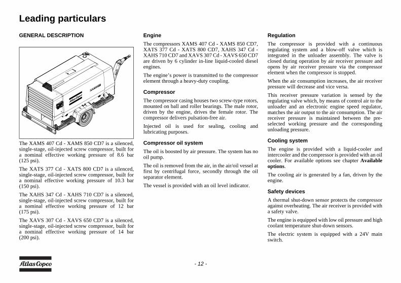
The XAMS 407 Cd - XAMS 850 CD7 is a silenced,single-stage, oil-injected screw compressor, built fora nominal effective working pressure of 8.6 bar(125 psi).The XATS 377 Cd - XATS 800 CD7 is a silenced,single-stage, oil-injected screw compressor, built fora nominal effective working pressure of 10.3 bar(150 psi).The XAHS 347 Cd - XAHS 710 CD7 is a silenced,single-stage, oil-injected screw compressor, built fora nominal effective working pressure of 12 bar(175 psi).The XAVS 307 Cd - XAVS 650 CD7 is a silenced,single-stage, oil-injected screw compressor, built fora nominal effective working pressure of 14 bar(200 psi).
EngineThe compressors XAMS 407 Cd - XAMS 850 CD7,XATS 377 Cd - XATS 800 CD7, XAHS 347 Cd -XAHS 710 CD7 and XAVS 307 Cd - XAVS 650 CD7are driven by 6 cylinder in-line liquid-cooled dieselengines.The engine’s power is transmitted to the compressorelement through a heavy-duty coupling.
CompressorThe compressor casing houses two screw-type rotors,mounted on ball and roller bearings. The male rotor,driven by the engine, drives the female rotor. Thecompressor delivers pulsation-free air.Injected oil is used for sealing, cooling andlubricating purposes.
Compressor oil systemThe oil is boosted by air pressure. The system has nooil pump.The oil is removed from the air, in the air/oil vessel atfirst by centrifugal force, secondly through the oilseparator element.The vessel is provided with an oil level indicator.
RegulationThe compressor is provided with a continuousregulating system and a blow-off valve which isintegrated in the unloader assembly. The valve isclosed during operation by air receiver pressure andopens by air receiver pressure via the compressorelement when the compressor is stopped.When the air consumption increases, the air receiverpressure will decrease and vice versa.This receiver pressure variation is sensed by theregulating valve which, by means of control air to theunloader and an electronic engine speed regulator,matches the air output to the air consumption. The airreceiver pressure is maintained between the pre-selected working pressure and the correspondingunloading pressure.
Cooling systemThe engine is provided with a liquid-cooler andintercooler and the compressor is provided with an oilcooler. For available options see chapter Availableoptions. The cooling air is generated by a fan, driven by theengine.
Safety devicesA thermal shut-down sensor protects the compressoragainst overheating. The air receiver is provided witha safety valve.The engine is equipped with low oil pressure and highcoolant temperature shut-down sensors.The electric system is equipped with a 24V mainswitch.
- 12 -
Frame and axlesThe compressor/engine unit is supported by rubberbuffers in the frame.The standard compressor has an adjustable or fixedtowbar with brakes.The braking system consists of an integrated parkingbrake and overrunbrake. When driving backwards theoverrunbrake is not engaged automatically. (Foravailable options see chapter Available options.)
BodyworkThe bodywork has openings at the shaped front andrear end for the intake and outlet of cooling air andhinged doors for maintenance and service operations.The bodywork is internally lined with sound-absorbing material.
Lifting eyeA lifting eye is accessible when a small door at the topof the unit is unlocked.
Control panelThe control panel grouping the air pressure gauge,control switch etc., is placed at the left hand/ rear endcorner.
Data plateThe compressor is furnished with a data plateshowing the product code, the unit serial number andthe working pressure (see chapter Dataplate).
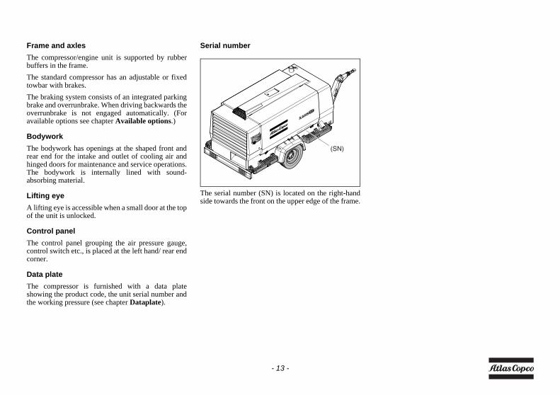
Serial number
The serial number (SN) is located on the right-handside towards the front on the upper edge of the frame.
xxxx xxxxx
(SN)
- 13 -
Main Parts
(FFac)
(OFce)
(AFce)
(FLS)
(FCft)
(FT)
(LV)
(MPV)
(CE)
(CP)(FPco)
(AR)
(SN)
(OFe)
(BS)
(D)
(A)
(OC)
(R)
(CT)
(FCc)
(TB)(F)
(EP)
(B)
(OLG)(ES)
(AOV)
(AFe)(SV)
(RV)
(E)
(IC)
(FF)
- 14 -
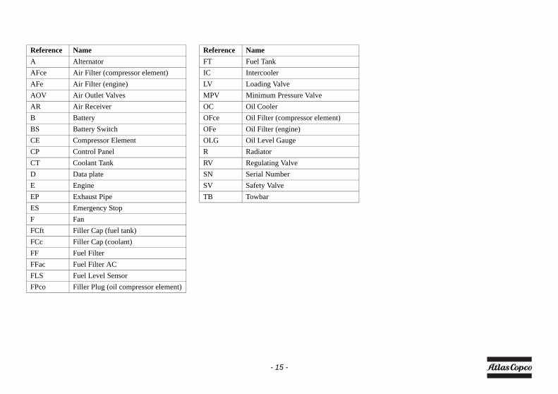
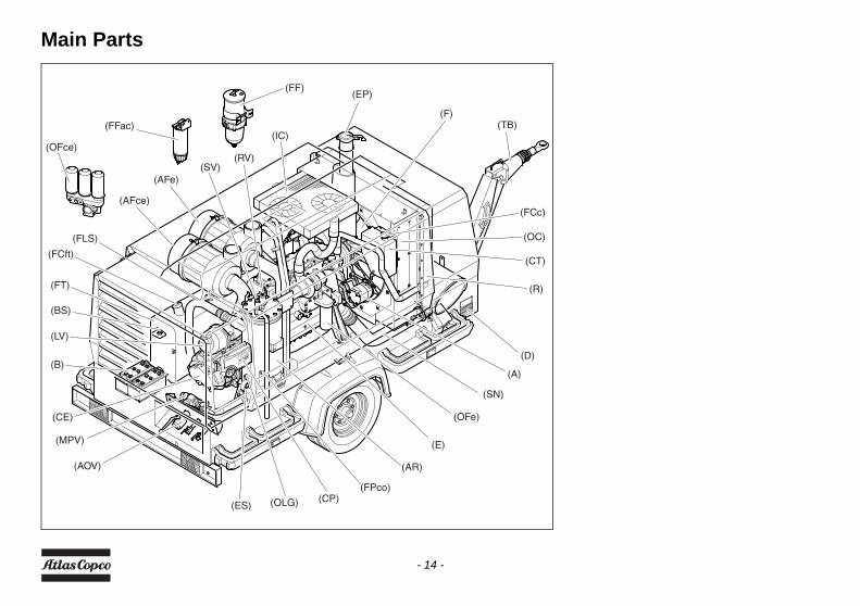
Reference NameA AlternatorAFce Air Filter (compressor element)AFe Air Filter (engine)AOV Air Outlet ValvesAR Air ReceiverB BatteryBS Battery SwitchCE Compressor ElementCP Control PanelCT Coolant TankD Data plateE EngineEP Exhaust PipeES Emergency StopF FanFCft Filler Cap (fuel tank)FCc Filler Cap (coolant)FF Fuel FilterFFac Fuel Filter ACFLS Fuel Level SensorFPco Filler Plug (oil compressor element)
Reference NameFT Fuel TankIC IntercoolerLV Loading ValveMPV Minimum Pressure ValveOC Oil CoolerOFce Oil Filter (compressor element)OFe Oil Filter (engine)OLG Oil Level GaugeR RadiatorRV Regulating ValveSN Serial NumberSV Safety ValveTB Towbar
- 15 -
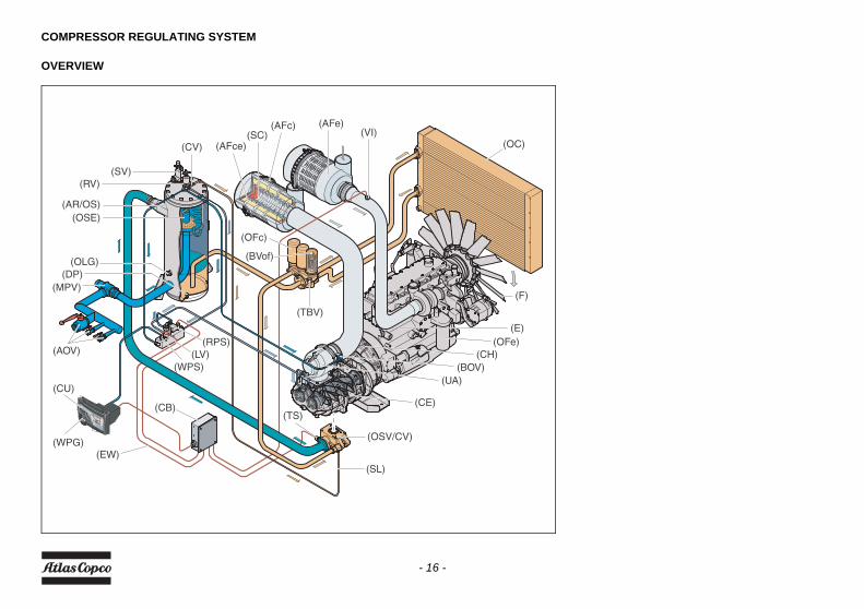
COMPRESSOR REGULATING SYSTEM
OVERVIEW
(F)
(TBV)
(OFc)
(BVof)
(AFe)(VI)
(CE)
(UA)
(OFe)(CH)
(BOV)
(E)
(AOV)
(CB)
(EW)
(CU)
(WPG)
(RPS)(LV)
(WPS)
(OLG)(DP)
(MPV)
(AR/OS)(OSE)
(AFc)(SC)
(AFce)(CV)
(SV)(RV)
(TS)
(SL)
(OSV/CV)
(OC)
- 16 -
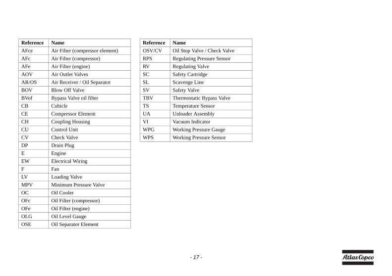
Reference NameAFce Air Filter (compressor element)AFc Air Filter (compressor)AFe Air Filter (engine)AOV Air Outlet ValvesAR/OS Air Receiver / Oil SeparatorBOV Blow Off ValveBVof Bypass Valve oil filterCB CubicleCE Compressor ElementCH Coupling HousingCU Control UnitCV Check ValveDP Drain PlugE EngineEW Electrical WiringF FanLV Loading ValveMPV Minimum Pressure ValveOC Oil CoolerOFc Oil Filter (compressor)OFe Oil Filter (engine)OLG Oil Level GaugeOSE Oil Separator Element
Reference NameOSV/CV Oil Stop Valve / Check ValveRPS Regulating Pressure SensorRV Regulating ValveSC Safety CartridgeSL Scavenge LineSV Safety ValveTBV Thermostatic Bypass ValveTS Temperature SensorUA Unloader AssemblyVI Vacuum IndicatorWPG Working Pressure GaugeWPS Working Pressure Sensor
- 17 -
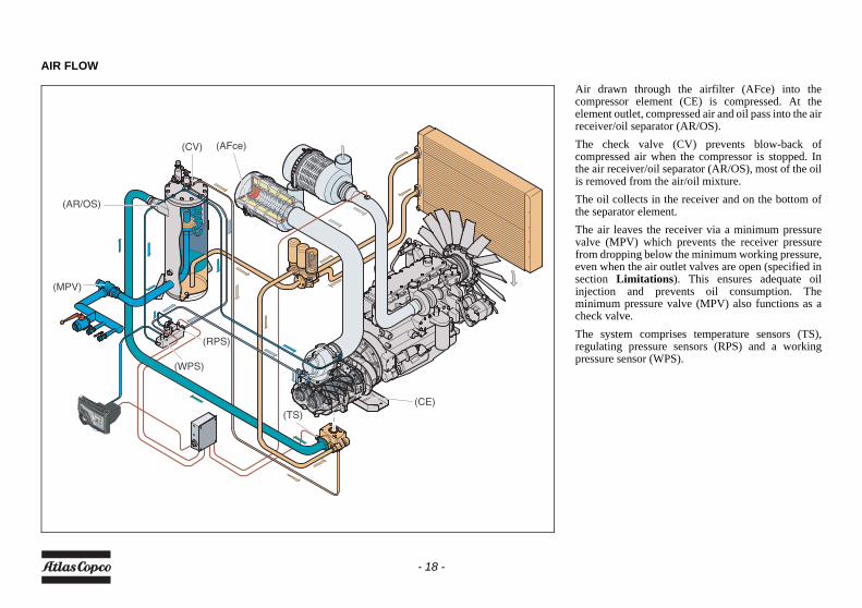
AIR FLOW
Air drawn through the airfilter (AFce) into thecompressor element (CE) is compressed. At theelement outlet, compressed air and oil pass into the airreceiver/oil separator (AR/OS).The check valve (CV) prevents blow-back ofcompressed air when the compressor is stopped. Inthe air receiver/oil separator (AR/OS), most of the oilis removed from the air/oil mixture.The oil collects in the receiver and on the bottom ofthe separator element.The air leaves the receiver via a minimum pressurevalve (MPV) which prevents the receiver pressurefrom dropping below the minimum working pressure,even when the air outlet valves are open (specified insection Limitations). This ensures adequate oilinjection and prevents oil consumption. Theminimum pressure valve (MPV) also functions as acheck valve.The system comprises temperature sensors (TS),regulating pressure sensors (RPS) and a workingpressure sensor (WPS).
(CE)
(RPS)
(WPS)
(MPV)
(AR/OS)
(AFce)(CV)
(TS)
- 18 -
OIL SYSTEM
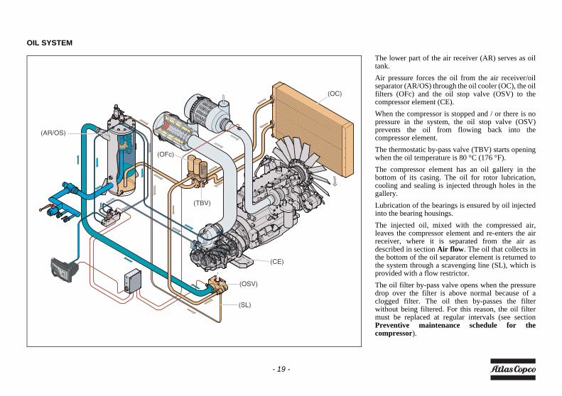
The lower part of the air receiver (AR) serves as oiltank.Air pressure forces the oil from the air receiver/oilseparator (AR/OS) through the oil cooler (OC), the oilfilters (OFc) and the oil stop valve (OSV) to thecompressor element (CE).When the compressor is stopped and / or there is nopressure in the system, the oil stop valve (OSV)prevents the oil from flowing back into thecompressor element.The thermostatic by-pass valve (TBV) starts openingwhen the oil temperature is 80 °C (176 °F).The compressor element has an oil gallery in thebottom of its casing. The oil for rotor lubrication,cooling and sealing is injected through holes in thegallery.Lubrication of the bearings is ensured by oil injectedinto the bearing housings.The injected oil, mixed with the compressed air,leaves the compressor element and re-enters the airreceiver, where it is separated from the air asdescribed in section Air flow. The oil that collects inthe bottom of the oil separator element is returned tothe system through a scavenging line (SL), which isprovided with a flow restrictor.The oil filter by-pass valve opens when the pressuredrop over the filter is above normal because of aclogged filter. The oil then by-passes the filterwithout being filtered. For this reason, the oil filtermust be replaced at regular intervals (see sectionPreventive maintenance schedule for thecompressor).
(TBV)
(OFc)
(CE)
(AR/OS)
(SL)
(OSV)
(OC)
- 19 -
CONTINUOUS REGULATING SYSTEM
(CE)
(UA)(BOV)
(AR)
(RV)
- 20 -
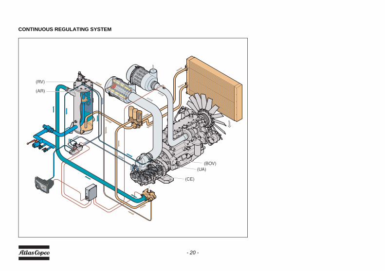
The compressor is provided with a continuousregulating system and a blow-off valve (BOV) whichis integrated in the unloader assembly (UA). Thevalve is closed during operation by outlet pressure ofthe compressor element and opens by air receiverpressure when the compressor is stopped.When the air consumption increases, the air receiverpressure will decrease and vice versa. This receiverpressure variation is sensed by the regulating valve(RV) which, by means of control air to the unloaderassembly (UA), matches the air output to the airconsumption. The air receiver pressure is maintainedbetween the pre-selected working pressure and thecorresponding unloading pressure.When starting the compressor, the throttle valve iskept closed via receiver pressure. The compressorelement (CE) takes in air and pressure builds up in thereceiver (AR). The throttle valve is closed. The airoutput is controlled from maximum output (100%) tono output (0%) by:1. Speed control of the engine between maximum
load speed and unloading speed (the output of a screw compressor is proportional to the rotating speed).
2. Air inlet throttling.If the air consumption is equal to or exceeds themaximum air output, the engine speed is held atmaximum load speed and the throttle valve is fullyopen.
If the air consumption is less than the maximum airoutput, air receiver pressure increases and theregulating valve supplies control air to throttle valveto reduce the air output and holds air receiver pressurebetween the normal working pressure and thecorresponding unloading pressure. Unloadingpressure = normal working pressure + 1 bar(14.504 psi).When the air consumption is resumed, the blow offvalve (BOV) closes and the throttle valve graduallyopens the air intake and the electronic speed regulatorincreases the engine speed.The construction of the regulating valve (RV) is suchthat any increase (decrease) of the air receiverpressure above the pre-set valve opening pressureresults in a proportional increase (decrease) of thecontrol pressure to the throttle valve and theelectronic speed regulator.Part of the control air is vented to atmosphere, andany condensate discharged, through the vent holes.
- 21 -
ELECTRIC SYSTEM
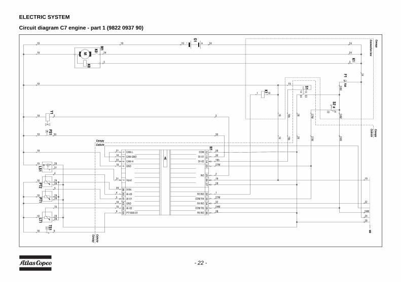
Circuit diagram C7 engine - part 1 (9822 0937 90)
LS1
+-
19
18
18
18
28
19
32
24M
28
24
Canopy
Connection box
24M
1919
24
24M
19
19b
28 27M
24M
19
19 24
+
19 24
G1
-
34 33
14 13S1
S2 a2122
15AF1
19 24
33
24
K1
K0
K0M
M1
1 19
K130
2
19b
28 27M
28
5
29PT1
28
4
29PT2
29
15
28LT1
19
3119
2625
2723
3534
3336
3214
1213
5449
4341
4038
47
31
2
PT1000-01
AI-02
GND
AI-01
AI-03
5Vdc
Input
GND
CAN-L
CAN-H
CAN-GND
COM R4
R4 NO
COM R5
R5 NO
R3 NO
NO
DI-02
DI-01
COM
N1
18
29
31
9
15
18
5
4
19
20
21
2
28
28
30
19b
27M
32
19
1
28
27M
24M
2
9
30
19
18
19
Y1TS1
CanopyCubicle
CubicleCanopy
CubicleCanopy
PPS1
A
B
- 22 -
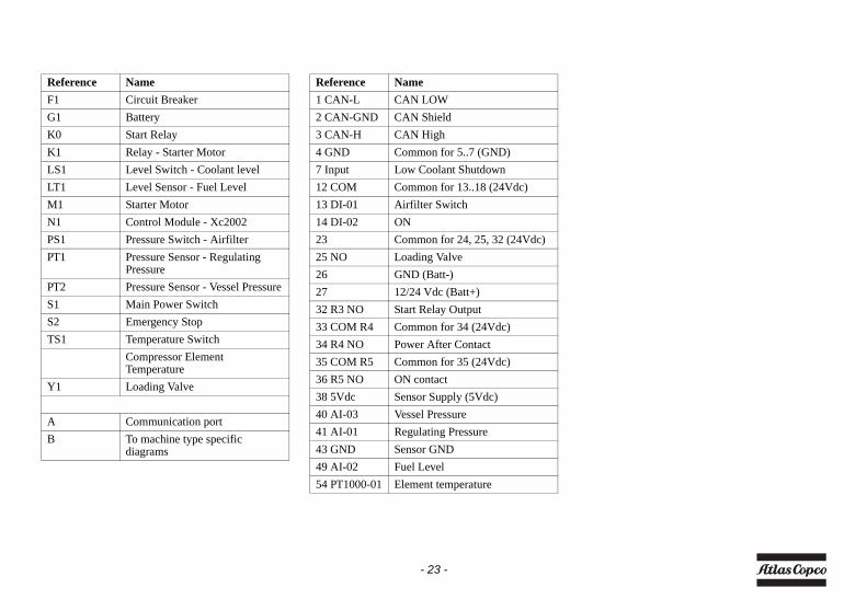
Reference NameF1 Circuit BreakerG1 BatteryK0 Start RelayK1 Relay - Starter MotorLS1 Level Switch - Coolant levelLT1 Level Sensor - Fuel LevelM1 Starter MotorN1 Control Module - Xc2002PS1 Pressure Switch - AirfilterPT1 Pressure Sensor - Regulating
PressurePT2 Pressure Sensor - Vessel PressureS1 Main Power SwitchS2 Emergency StopTS1 Temperature Switch
Compressor Element Temperature
Y1 Loading Valve
A Communication portB To machine type specific
diagrams
Reference Name1 CAN-L CAN LOW2 CAN-GND CAN Shield3 CAN-H CAN High4 GND Common for 5..7 (GND)7 Input Low Coolant Shutdown12 COM Common for 13..18 (24Vdc)13 DI-01 Airfilter Switch14 DI-02 ON23 Common for 24, 25, 32 (24Vdc)25 NO Loading Valve26 GND (Batt-)27 12/24 Vdc (Batt+)32 R3 NO Start Relay Output33 COM R4 Common for 34 (24Vdc)34 R4 NO Power After Contact35 COM R5 Common for 35 (24Vdc)36 R5 NO ON contact38 5Vdc Sensor Supply (5Vdc)40 AI-03 Vessel Pressure41 AI-01 Regulating Pressure43 GND Sensor GND49 AI-02 Fuel Level54 PT1000-01 Element temperature
- 23 -
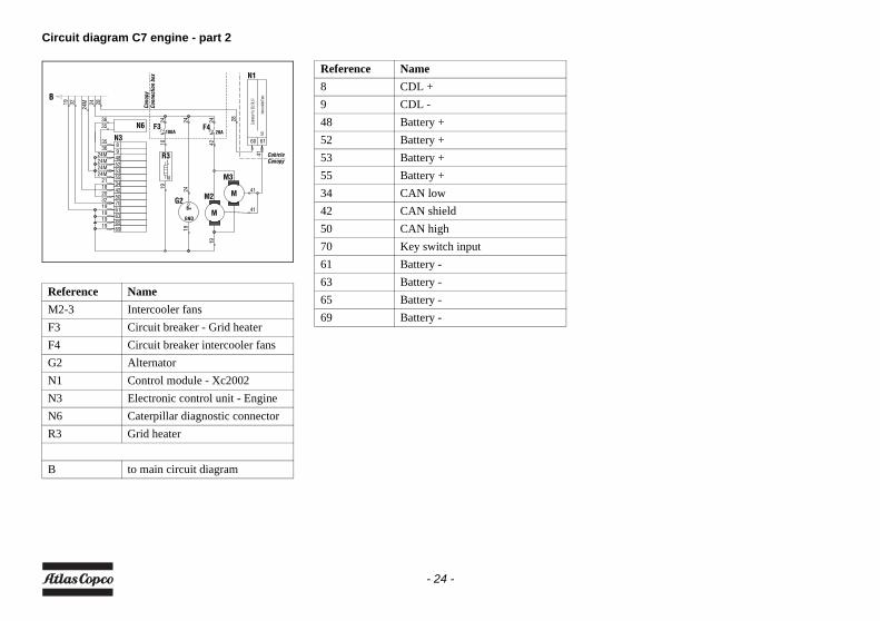
Circuit diagram C7 engine - part 2
Reference NameM2-3 Intercooler fansF3 Circuit breaker - Grid heaterF4 Circuit breaker intercooler fansG2 AlternatorN1 Control module - Xc2002N3 Electronic control unit - EngineN6 Caterpillar diagnostic connectorR3 Grid heater
B to main circuit diagram
Conn
ectio
n bo
xCa
nopy
CanopyCubicle
B2824
N1
M3
M2
19
28
1024
N
LR3
100AF3
1924
B+
GND
G2
24 24
20AF4
41
41
4219
M
M
60
Comm
on fo
r 58,
59, 6
1
61
NOInt
ercoo
ler Fa
ns4124M
24M
19
18
3536
19 32
N6
24M
35
32
191919
24M
N336
21
20
24M
69
4852
6563617050
5355
4234
98
Reference Name8 CDL +9 CDL -48 Battery +52 Battery +53 Battery +55 Battery +34 CAN low42 CAN shield50 CAN high70 Key switch input61 Battery -63 Battery -65 Battery -69 Battery -
- 24 -
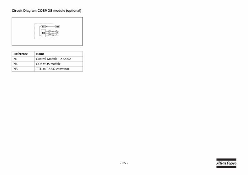
Circuit Diagram COSMOS module (optional)
Reference NameN1 Control Module - Xc2002N4 COSMOS moduleN5 TTL to RS232 convertor
1924M28
GNDB+PAC
N1N5
N4
- 25 -
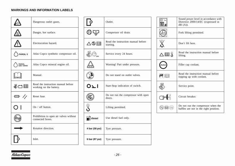
MARKINGS AND INFORMATION LABELS
Dangerous outlet gases.
Danger, hot surface.
Electrocution hazard.
Atlas Copco synthetic compressor oil.
Atlas Copco mineral engine oil.
Manual.
Read the instruction manual before working on the battery.
Reset fuse.
On / off button.
Prohibition to open air valves without connected hoses.
Rotation direction.
Inlet.
Outlet.
Compressor oil drain.
Read the instruction manual before starting.
Service every 24 hours.
Warning! Part under pressure.
Do not stand on outlet valves.
Start-Stop indication of switch.
Do not run the compressor with open doors.
Lifting permitted.
Use diesel fuel only.
4 bar (58 psi) Tyre pressure.
6 bar (87 psi) Tyre pressure.
Sound power level in accordance with Directive 2000/14/EC (expressed in dB (A)).
Fork lifting permitted.
Don’t lift here.
Read the instruction manual before lifting.
Filler cap coolant.
Read the instruction manual before topping up with coolant.
Service point.
Circuit breaker.
Do not run the compressor when the baffles are not in the right position.
- 26 -
Operating instructionsPARKING, TOWING AND LIFTING INSTRUCTIONS
Safety precautions
Attention
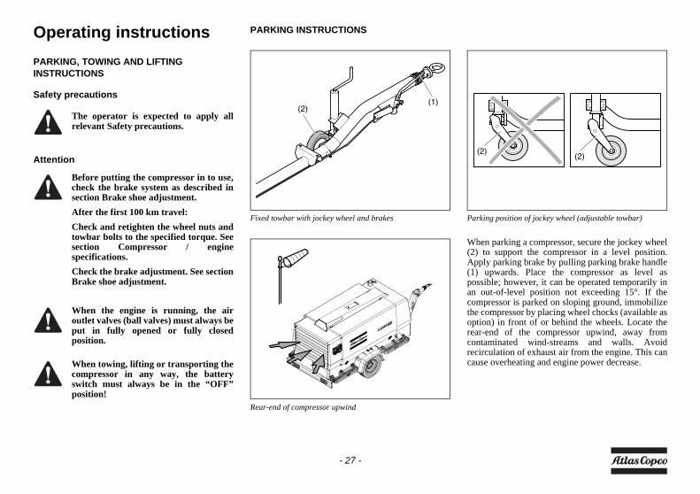
PARKING INSTRUCTIONS
Fixed towbar with jockey wheel and brakes
Rear-end of compressor upwind
Parking position of jockey wheel (adjustable towbar)
When parking a compressor, secure the jockey wheel(2) to support the compressor in a level position.Apply parking brake by pulling parking brake handle(1) upwards. Place the compressor as level aspossible; however, it can be operated temporarily inan out-of-level position not exceeding 15°. If thecompressor is parked on sloping ground, immobilizethe compressor by placing wheel chocks (available asoption) in front of or behind the wheels. Locate therear-end of the compressor upwind, away fromcontaminated wind-streams and walls. Avoidrecirculation of exhaust air from the engine. This cancause overheating and engine power decrease.
The operator is expected to apply allrelevant Safety precautions.
Before putting the compressor in to use,check the brake system as described insection Brake shoe adjustment.After the first 100 km travel:Check and retighten the wheel nuts andtowbar bolts to the specified torque. Seesection Compressor / enginespecifications.Check the brake adjustment. See sectionBrake shoe adjustment.
When the engine is running, the airoutlet valves (ball valves) must always beput in fully opened or fully closedposition.
When towing, lifting or transporting thecompressor in any way, the batteryswitch must always be in the “OFF”position!
(2)(1)
(2)(2)
- 27 -
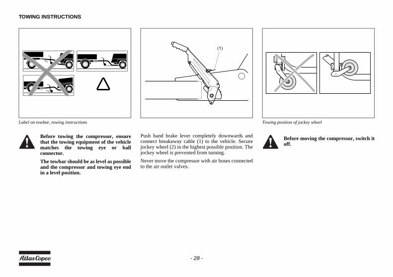
TOWING INSTRUCTIONS
Label on towbar, towing instructions
Push hand brake lever completely downwards andconnect breakaway cable (1) to the vehicle. Securejockey wheel (2) in the highest possible position. Thejockey wheel is prevented from turning.Never move the compressor with air hoses connectedto the air outlet valves.
Towing position of jockey wheel
Before towing the compressor, ensurethat the towing equipment of the vehiclematches the towing eye or ballconnector.The towbar should be as level as possibleand the compressor and towing eye endin a level position.
(1)
Before moving the compressor, switch itoff.
- 28 -
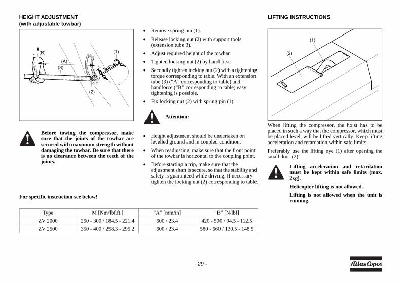
HEIGHT ADJUSTMENT(with adjustable towbar)
• Remove spring pin (1).• Release locking nut (2) with support tools
(extension tube 3).• Adjust required height of the towbar.• Tighten locking nut (2) by hand first.• Secondly tighten locking nut (2) with a tightening
torque corresponding to table. With an extension tube (3) (“A” corresponding to table) and handforce (“B” corresponding to table) easy tightening is possible.
• Fix locking nut (2) with spring pin (1).
• Height adjustment should be undertaken on levelled ground and in coupled condition.
• When readjusting, make sure that the front point of the towbar is horizontal to the coupling point.
• Before starting a trip, make sure that the adjustment shaft is secure, so that the stability and safety is guaranteed while driving. If necessary tighten the locking nut (2) corresponding to table.
LIFTING INSTRUCTIONS
When lifting the compressor, the hoist has to beplaced in such a way that the compressor, which mustbe placed level, will be lifted vertically. Keep liftingacceleration and retardation within safe limits.Preferably use the lifting eye (1) after opening thesmall door (2).
Before towing the compressor, makesure that the joints of the towbar aresecured with maximum strength withoutdamaging the towbar. Be sure that thereis no clearance between the teeth of thejoints.
(B)
(2)
(1)
(A)(3)
For specific instruction see below!
Type M [Nm/lbf.ft.] ”A” [mm/in] ”B” [N/lbf]ZV 2000 250 - 300 / 184.5 - 221.4 600 / 23.4 420 - 500 / 94.5 - 112.5ZV 2500 350 - 400 / 258.3 - 295.2 600 / 23.4 580 - 660 / 130.5 - 148.5
Attention:
Lifting acceleration and retardationmust be kept within safe limits (max.2xg).Helicopter lifting is not allowed.Lifting is not allowed when the unit isrunning.
(1)
(2)
- 29 -
STARTING / STOPPING
BEFORE STARTING
1. Before initial start-up, prepare battery for operation if not already done. See section Recharging a battery.
2. With the compressor standing level, check the level of the engine oil. Add oil, if necessary, to the upper mark on dipstick. Also check the engine coolant level. Consult the Engine Operation Manual for the type of coolant and type and viscosity grade of the engine oil.
3. Check the level of the compressor oil. The pointer of oil level gauge (OLG) should register in the green range. Add oil if necessary. See section Engine oil for the oil to be used.
4. Check that the fuel tank contains sufficient fuel. Top up, if necessary. Consult the Engine Operation Manual for the type of fuel.
5. Drain any water and sediment from the fuel filters until clean fuel flows from the drain cock. See section Priming instructions.
6. Empty the dust trap of each air filter (AF). See section Cleaning the dust trap.
7. Clogged air filter(s) will be indicated on the display of the control panel, see section Fault codes. If indicated, replace the filter elements.
8. Check coolant level in engine coolant top tank. Top up, if necessary. Consult the Engine Operation Manual for coolant specifications.
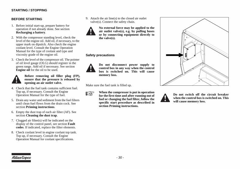
9. Attach the air line(s) to the closed air outlet valve(s). Connect the safety chain.
Safety precautions
Make sure the fuel tank is filled up.
Before removing oil filler plug (FP),ensure that the pressure is released byopening an air outlet valve.
No external force may be applied to theair outlet valve(s), e.g. by pulling hosesor by connecting equipment directly tothe valve(s).
Do not disconnect power supply tocontrol box in any way when the controlbox is switched on. This will causememory loss.
When the compressor is put in operationfor the first time and after running out offuel or changing the fuel filter, follow thespecific start procedure as described insection Priming instructions.
Do not switch off the circuit breakerwhen the control box is switched on. Thiswill cause memory loss.
- 30 -
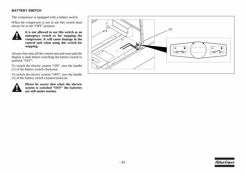
BATTERY SWITCH
The compressor is equipped with a battery switch.When the compressor is not in use this switch mustalways be in the “OFF” position.
Always first shut off the control unit and wait until thedisplay is dark before switching the battery switch toposition “OFF”.To switch the electric system “ON”, turn the handle(1) of the battery switch clockwise.To switch the electric system “OFF”, turn the handle(1) of the battery switch counterclockwise.
It is not allowed to use this switch as anemergency switch or for stopping thecompressor. It will cause damage in thecontrol unit when using this switch forstopping.
Please be aware that when the electricsystem is switched “OFF” the batteriesare still under tension.
(1)
- 31 -
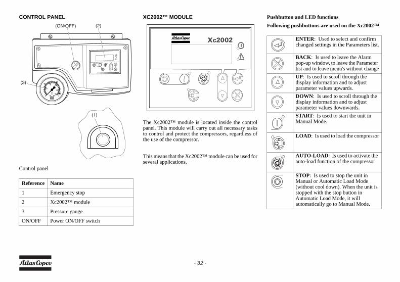
CONTROL PANEL
Control panel
XC2002™ MODULE
The Xc2002™ module is located inside the controlpanel. This module will carry out all necessary tasksto control and protect the compressors, regardless ofthe use of the compressor.
This means that the Xc2002™ module can be used forseveral applications.
Pushbutton and LED functionsFollowing pushbuttons are used on the Xc2002™
Reference Name
1 Emergency stop
2 Xc2002™ module
3 Pressure gauge
ON/OFF Power ON/OFF switch
(2)
(3)
(ON/OFF)
(1)
ENTER: Used to select and confirm changed settings in the Parameters list.
BACK: Is used to leave the Alarm pop-up window, to leave the Parameter list and to leave menu's without changeUP: Is used to scroll through the display information and to adjust parameter values upwards.DOWN: Is used to scroll through the display information and to adjust parameter values downwards.START: Is used to start the unit in Manual Mode.
LOAD: Is used to load the compressor
AUTO-LOAD: Is used to activate the auto-load function of the compressor
STOP: Is used to stop the unit in Manual or Automatic Load Mode (without cool down). When the unit is stopped with the stop button in Automatic Load Mode, it will automatically go to Manual Mode.
- 32 -
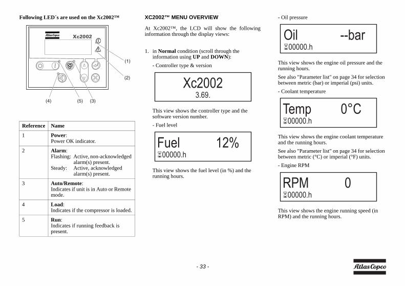
Following LED´s are used on the Xc2002™ XC2002™ MENU OVERVIEW
At Xc2002™, the LCD will show the followinginformation through the display views:
1. in Normal condition (scroll through the information using UP and DOWN):- Controller type & version
This view shows the controller type and the software version number.- Fuel level
This view shows the fuel level (in %) and the running hours.
- Oil pressure
This view shows the engine oil pressure and the running hours.See also "Parameter list" on page 34 for selection between metric (bar) or imperial (psi) units.- Coolant temperature
This view shows the engine coolant temperature and the running hours.See also "Parameter list" on page 34 for selection between metric (°C) or imperial (°F) units.- Engine RPM
This view shows the engine running speed (in RPM) and the running hours.
Reference Name
1 Power:Power OK indicator.
2 Alarm:Flashing: Active, non-acknowledged
alarm(s) present.Steady: Active, acknowledged
alarm(s) present.
3 Auto/Remote:Indicates if unit is in Auto or Remote mode.
4 Load:Indicates if the compressor is loaded.
5 Run:Indicates if running feedback is present.
(1)
(2)
(4) (5) (3)
Xc20023.69.
Fuel 12%�00000.h
Oil --bar�00000.h
Temp 0°C�00000.h
RPM 0�00000.h
- 33 -
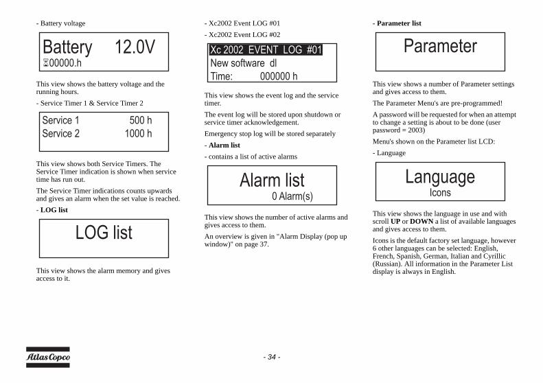
- Battery voltage
This view shows the battery voltage and the running hours.- Service Timer 1 & Service Timer 2
This view shows both Service Timers. The Service Timer indication is shown when service time has run out.The Service Timer indications counts upwards and gives an alarm when the set value is reached.- LOG list
This view shows the alarm memory and gives access to it.
- Xc2002 Event LOG #01- Xc2002 Event LOG #02
This view shows the event log and the service timer.The event log will be stored upon shutdown or service timer acknowledgement.Emergency stop log will be stored separately- Alarm list- contains a list of active alarms
This view shows the number of active alarms and gives access to them. An overview is given in "Alarm Display (pop up window)" on page 37.
- Parameter list
This view shows a number of Parameter settings and gives access to them.The Parameter Menu's are pre-programmed!A password will be requested for when an attempt to change a setting is about to be done (user password = 2003)Menu's shown on the Parameter list LCD:- Language
This view shows the language in use and with scroll UP or DOWN a list of available languages and gives access to them.Icons is the default factory set language, however 6 other languages can be selected: English, French, Spanish, German, Italian and Cyrillic (Russian). All information in the Parameter List display is always in English.
Battery 12.0V�00000.h
Service 1 500 h
Service 2 1000 h
LOG list
Xc 2002 EVENT LOG #01
New software dl
Time: 000000 h
Alarm list0 Alarm(s)
Parameter
LanguageIcons
- 34 -
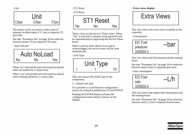
- Unit
This menu can be accessed to select units of measure in either metric (°C, bar) or imperial (°F, psi) units.See also "Parameter list" on page 34 for selection between metric (°C) or imperial (°F) units.- Auto NoLoad
When "no" selected the unit will remain in unload when not loaded for a certain time.When "yes" selected the unit will switch to noload when running unload for a certain time.
- ST1 Reset- ST2 Reset
These views are the Service Timer resets. When "Yes" is selected a customer level password will be requested prior to approving the Service Timer Reset.When a service timer alarm occurs and is acknowledged, the service timer will be reset automatically.- Unit Type
This view shows the model type of the compressor.1 = default unit typeIt is possible to scroll between configuration menu's by using the pushbuttons UP and DOWN.Pushing the ENTER button activates the configuration menu which is shown on the display.
- Extra views display
This view shows the extra views available in the controller.- Fuel pressure
This view shows the fuel pressure and the running hours.See also "Parameter list" on page 34 for selection between metric (bar) or imperial (psi) units.- Fuel consumption
This view shows the engine fuel consumption and the running hours.See also "Parameter list" on page 34 for selection between metric (L/h) or imperial (Gal/h) units.
UnitC/bar C/bar F/psi
Auto NoLoadNo No Yes
ST1 ResetNo No Yes
Unit Type1 1 10
Extra Views
E|C Fuel
pressure
�00000.h
--bar
E|C Fuel
rate
�00000.h
--L/h
- 35 -
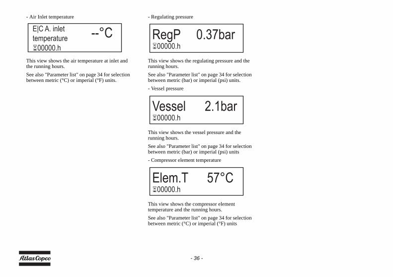
- Air Inlet temperature
This view shows the air temperature at inlet and the running hours.See also "Parameter list" on page 34 for selection between metric (°C) or imperial (°F) units.
- Regulating pressure
This view shows the regulating pressure and the running hours.See also "Parameter list" on page 34 for selection between metric (bar) or imperial (psi) units.- Vessel pressure
This view shows the vessel pressure and the running hours.See also "Parameter list" on page 34 for selection between metric (bar) or imperial (psi) units- Compressor element temperature
This view shows the compressor element temperature and the running hours.See also "Parameter list" on page 34 for selection between metric (°C) or imperial (°F) units
E|C A. inlet
temperature
�00000.h
--°C RegP 0.37bar�00000.h
Vessel 2.1bar�00000.h
Elem.T 57°C�00000.h
- 36 -
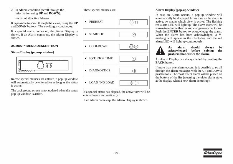
2. in Alarm condition (scroll through the information using UP and DOWN):- a list of all active Alarms
It is possible to scroll through the views, using the UPand DOWN buttons. The scrolling is continuous.If a special status comes up, the Status Display isshown. If an Alarm comes up, the Alarm Display isshown.
XC2002™ MENU DESCRIPTION
Status Display (pop-up window)
In case special statuses are entered, a pop-up windowwill automatically be entered for as long as the statusis active.The background screen is not updated when the statuspop-up window is active.
These special statuses are:
If a special status has elapsed, the active view will beentered again automatically.If an Alarm comes up, the Alarm Display is shown.
Alarm Display (pop-up window)In case an Alarm occurs, a pop-up window willautomatically be displayed for as long as the alarm isactive, no matter which view is active. The flashingred alarm LED will light up. The alarm icons will beshown together with an acknowledgement check-box.Push the ENTER button to acknowledge the alarm.When the alarm has been acknowledged, a V-marking will appear in the check-box and the redalarm LED will light up continuously.
An Alarm Display can always be left by pushing theBACK button.If more than one alarm occurs, it is possible to scrollthrough the alarm messages with the UP and DOWNpushbuttons. The most recent alarm will be placed onthe bottom of the list (meaning the older alarm staysat the display when a new alarm comes up).
Fuel 12%�00000.h
• PREHEAT
• START OF
• COOLDOWN
• EXT. STOP TIME
• DIAGNOSTICS
• LOAD / NO LOAD
An alarm should always beacknowledged before solving theproblem that causes the alarm.
- 37 -
List of possible alarms:
If a shutdown comes up, the Shutdown Display isshown.
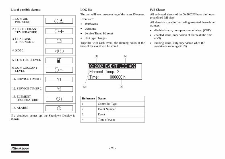
LOG listThe unit will keep an event log of the latest 15 events.Events are:• shutdowns• warnings• Service Timer 1/2 reset• Unit type changesTogether with each event, the running hours at thetime of the event will be stored.
Fail ClassesAll activated alarms of the Xc2002™ have their ownpredefined fail class.All alarms are enabled according to one of these threestatuses:• disabled alarm, no supervision of alarm (OFF)• enabled alarm, supervision of alarm all the time
(ON)• running alarm, only supervision when the
machine is running (RUN)
1. LOW OIL PRESSURE
2. HIGH COOLANT TEMPERATURE
3. CHARGING ALTERNATOR
4. XDEC
5. LOW FUEL LEVEL
6. LOW COOLANT LEVEL
11. SERVICE TIMER 1
12. SERVICE TIMER 2
13. ELEMENT TEMPERATURE
14. ALARM
Y1
Y2
!
Reference Name
1 Controller Type
2 Event Number
3 Event
4 Time of event
Xc 2002 EVENT LOG #02
Element Temp. 2
Time: 000000 h
(1) (2)
(3) (4)
- 38 -
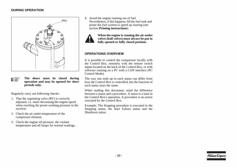
DURING OPERATION
Regularly carry out following checks:1. That the regulating valve (RV) is correctly
adjusted, i.e. starts decreasing the engine speed when reaching the preset working pressure in the receiver.
2. Check the air outlet temperature of the compressor element.
3. Check the engine oil pressure, the coolant temperature and all lamps for normal readings.
4. Avoid the engine running out of fuel. Nevertheless, if this happens, fill the fuel tank and prime the fuel system to speed up starting (see section Priming instructions).
OPERATIONS OVERVIEW
It is possible to control the compressor locally withthe Control Box, remotely with the remote switchinputs located on the back of the Control Box, or withsoftware running on a PC with a CAN interface (PCControl Mode).The way one ends up in each status can differ fromhow the Control Box is controlled, but the function ofeach status stays the same.When reading this document, mind the differencebetween a status and a procedure. A status is a state inthe Control Box's operation. A procedure is an actionexecuted by the Control Box.Example: The Stopping procedure is executed in theStopping status, the Start Failure status and theShutdown status.
The doors must be closed duringoperation and may be opened for shortperiods only.
(RV)
When the engine is running the air outletvalves (ball valves) must always be put infully opened or fully closed position.
- 39 -
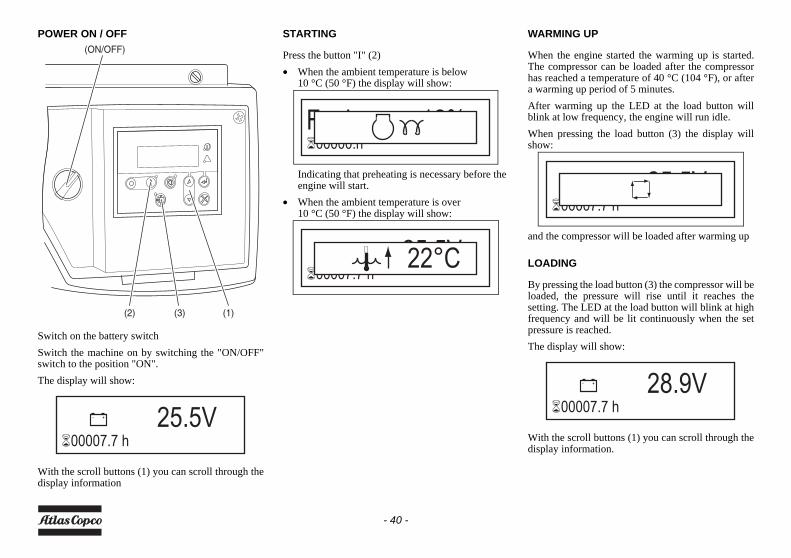
POWER ON / OFF
Switch on the battery switchSwitch the machine on by switching the "ON/OFF"switch to the position "ON".The display will show:
With the scroll buttons (1) you can scroll through thedisplay information
STARTING
Press the button "I" (2)• When the ambient temperature is below
10 °C (50 °F) the display will show:
Indicating that preheating is necessary before the engine will start.
• When the ambient temperature is over10 °C (50 °F) the display will show:
WARMING UP
When the engine started the warming up is started.The compressor can be loaded after the compressorhas reached a temperature of 40 °C (104 °F), or aftera warming up period of 5 minutes.After warming up the LED at the load button willblink at low frequency, the engine will run idle.When pressing the load button (3) the display willshow:
and the compressor will be loaded after warming up
LOADING
By pressing the load button (3) the compressor will beloaded, the pressure will rise until it reaches thesetting. The LED at the load button will blink at highfrequency and will be lit continuously when the setpressure is reached.The display will show:
With the scroll buttons (1) you can scroll through thedisplay information.
(1)(2)
(ON/OFF)
(3)
25.5V�00007.7 h
Fuel 12%�00000.h
25.5V�00007.7 h
22°C
25.5V�00007.7 h
28.9V�00007.7 h
- 40 -
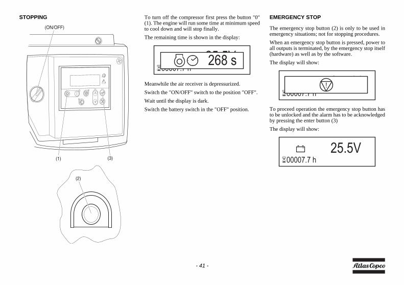
STOPPING To turn off the compressor first press the button "0"(1). The engine will run some time at minimum speedto cool down and will stop finally. The remaining time is shown in the display:
Meanwhile the air receiver is depressurized.Switch the "ON/OFF" switch to the position "OFF".Wait until the display is dark.Switch the battery switch in the "OFF" position.
EMERGENCY STOP
The emergency stop button (2) is only to be used inemergency situations; not for stopping procedures.When an emergency stop button is pressed, power toall outputs is terminated, by the emergency stop itself(hardware) as well as by the software.The display will show:
To proceed operation the emergency stop button hasto be unlocked and the alarm has to be acknowledgedby pressing the enter button (3)The display will show:
(1) (3)
(ON/OFF)
(2)
25.5V�00007.7 h
268 s
25.5V�00007.7 h
!
25.5V�00007.7 h
- 41 -
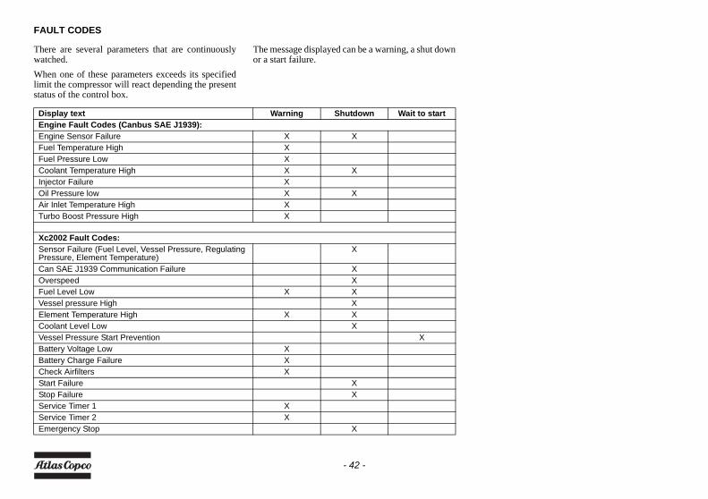
FAULT CODES
There are several parameters that are continuouslywatched.When one of these parameters exceeds its specifiedlimit the compressor will react depending the presentstatus of the control box.
The message displayed can be a warning, a shut downor a start failure.
Display text Warning Shutdown Wait to startEngine Fault Codes (Canbus SAE J1939):Engine Sensor Failure X XFuel Temperature High XFuel Pressure Low XCoolant Temperature High X XInjector Failure XOil Pressure low X XAir Inlet Temperature High XTurbo Boost Pressure High X
Xc2002 Fault Codes:Sensor Failure (Fuel Level, Vessel Pressure, Regulating Pressure, Element Temperature)
X
Can SAE J1939 Communication Failure XOverspeed XFuel Level Low X XVessel pressure High XElement Temperature High X XCoolant Level Low XVessel Pressure Start Prevention XBattery Voltage Low XBattery Charge Failure XCheck Airfilters XStart Failure XStop Failure XService Timer 1 XService Timer 2 XEmergency Stop X
- 42 -
MaintenanceLIABILITY
The manufacturer does not accept any liability for anydamage arising from the use of non-original parts andfor modifications, additions or conversions madewithout the manufacturer’s approval in writing.
SERVICE PAKS
A Service Pak is a collection of parts to be used for aspecific maintenance task, e.g. after 50, after 500 andafter 1000 running hours.It guarantees that all necessary parts are replaced atthe same time keeping down time to a minimum.The order number of the Service Paks are listed in theAtlas Copco Parts List (ASL).
Use of service paksService Paks include all genuine parts needed fornormal maintenance of both compressor and engine.Service Paks minimize downtime and keep yourmaintenance budget low.Order Service Paks at your local Atlas Copco dealer.
SERVICE KITS
A service kit is a collection of parts to fit a specificrepair or rebuilding task.It guarantees that all necessary parts are replaced atthe same time which improves the uptime of the unit.The order numbers of the Service Kits are listed in theAtlas Copco Parts List (ASL).
STORAGE
Run the compressor regularly, e.g. twice a week, untilwarm.Load and unload the compressor a few times tooperate the unloading and regulating components.Close the air outlet valves after stopping.
Contact Atlas Copco.
If the compressor is going to be storedwithout running from time to time,protective measures must be taken.
- 43 -
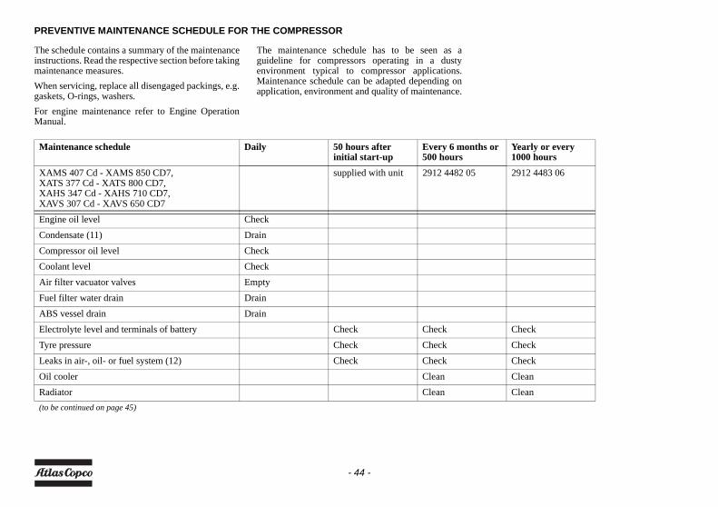
PREVENTIVE MAINTENANCE SCHEDULE FOR THE COMPRESSOR
The schedule contains a summary of the maintenanceinstructions. Read the respective section before takingmaintenance measures.When servicing, replace all disengaged packings, e.g.gaskets, O-rings, washers.For engine maintenance refer to Engine OperationManual.
The maintenance schedule has to be seen as aguideline for compressors operating in a dustyenvironment typical to compressor applications.Maintenance schedule can be adapted depending onapplication, environment and quality of maintenance.
Maintenance schedule Daily 50 hours after initial start-up
Every 6 months or 500 hours
Yearly or every 1000 hours
XAMS 407 Cd - XAMS 850 CD7,XATS 377 Cd - XATS 800 CD7,XAHS 347 Cd - XAHS 710 CD7,XAVS 307 Cd - XAVS 650 CD7
supplied with unit 2912 4482 05 2912 4483 06
Engine oil level CheckCondensate (11) DrainCompressor oil level CheckCoolant level CheckAir filter vacuator valves EmptyFuel filter water drain DrainABS vessel drain DrainElectrolyte level and terminals of battery Check Check CheckTyre pressure Check Check CheckLeaks in air-, oil- or fuel system (12) Check Check CheckOil cooler Clean CleanRadiator Clean Clean(to be continued on page 45)
- 44 -
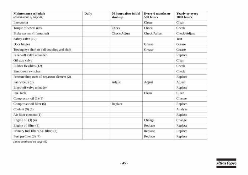
Maintenance schedule(continuation of page 44)
Daily 50 hours after initial start-up
Every 6 months or 500 hours
Yearly or every 1000 hours
Intercooler Clean CleanTorque of wheel nuts Check Check CheckBrake system (if installed) Check/Adjust Check/Adjust Check/AdjustSafety valve (10) TestDoor hinges Grease GreaseTowing eye shaft or ball coupling and shaft Grease GreaseBleed-off valve unloader ReplaceOil stop valve CleanRubber flexibles (12) CheckShut-down switches CheckPressure drop over oil separator element (2) ReplaceFan V-belts (3) Adjust Adjust AdjustBleed-off valve unloader ReplaceFuel tank Clean CleanCompressor oil (1) (8) ChangeCompressor oil filter (6) Replace ReplaceCoolant (9) (5) AnalyseAir filter element (1) ReplaceEngine oil (3) (4) Change ChangeEngine oil filter (3) Replace ReplacePrimary fuel filter (AC filter) (7) Replace ReplaceFuel prefilter (3) (7) Replace Replace(to be continued on page 45)
- 45 -
Notes
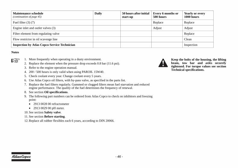
Maintenance schedule(continuation of page 45)
Daily 50 hours after initial start-up
Every 6 months or 500 hours
Yearly or every 1000 hours
Fuel filter (3) (7) Replace Replace
Engine inlet and outlet valves (3) Adjust Adjust
Filter element from regulating valve Replace
Flow restrictor in oil scavenge line Clean
Inspection by Atlas Copco Service Technician Inspection
1. More frequently when operating in a dusty environment.2. Replace the element when the pressure drop exceeds 0.8 bar (11.6 psi).3. Refer to the engine operation manual.4. 200 / 500 hours is only valid when using PAROIL 15W40.5. Check coolant every year. Change coolant every 5 years.6. Use Atlas Copco oil filters, with by-pass valve, as specified in the parts list.7. Replace the fuel filters regularly. Gummed or clogged filters mean fuel starvation and reduced
engine performance. The quality of the fuel determines the frequency of renewal.8. See section Oil specifications.9. The following part numbers can be ordered from Atlas Copco to check on inhibitors and freezing
point:• 2913 0028 00 refractometer• 2913 0029 00 pH meter.
10. See section Safety valve.11. See section Before starting.12. Replace all rubber flexibles each 6 years, according to DIN 20066.
Keep the bolts of the housing, the liftingbeam, tow bar and axles securelytightened. For torque values see sectionTechnical specifications.
- 46 -
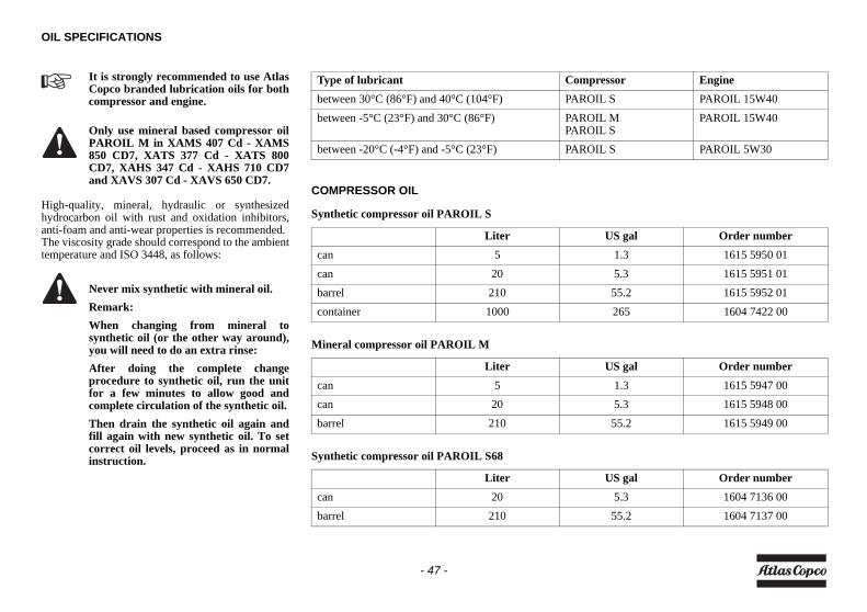
OIL SPECIFICATIONS
High-quality, mineral, hydraulic or synthesizedhydrocarbon oil with rust and oxidation inhibitors,anti-foam and anti-wear properties is recommended.The viscosity grade should correspond to the ambienttemperature and ISO 3448, as follows:
It is strongly recommended to use AtlasCopco branded lubrication oils for bothcompressor and engine.
Only use mineral based compressor oilPAROIL M in XAMS 407 Cd - XAMS850 CD7, XATS 377 Cd - XATS 800CD7, XAHS 347 Cd - XAHS 710 CD7and XAVS 307 Cd - XAVS 650 CD7.
Never mix synthetic with mineral oil.Remark:When changing from mineral tosynthetic oil (or the other way around),you will need to do an extra rinse:After doing the complete changeprocedure to synthetic oil, run the unitfor a few minutes to allow good andcomplete circulation of the synthetic oil.Then drain the synthetic oil again andfill again with new synthetic oil. To setcorrect oil levels, proceed as in normalinstruction.
COMPRESSOR OIL
Synthetic compressor oil PAROIL S
Mineral compressor oil PAROIL M
Synthetic compressor oil PAROIL S68
Liter US gal Order numbercan 5 1.3 1615 5950 01can 20 5.3 1615 5951 01barrel 210 55.2 1615 5952 01container 1000 265 1604 7422 00
Liter US gal Order numbercan 5 1.3 1615 5947 00can 20 5.3 1615 5948 00barrel 210 55.2 1615 5949 00
Liter US gal Order numbercan 20 5.3 1604 7136 00barrel 210 55.2 1604 7137 00
Type of lubricant Compressor Enginebetween 30°C (86°F) and 40°C (104°F) PAROIL S PAROIL 15W40between -5°C (23°F) and 30°C (86°F) PAROIL M
PAROIL SPAROIL 15W40
between -20°C (-4°F) and -5°C (23°F) PAROIL S PAROIL 5W30
- 47 -
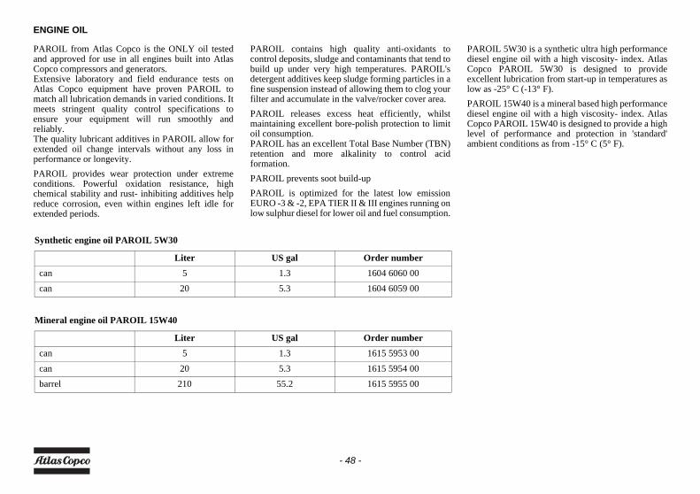
ENGINE OIL
PAROIL from Atlas Copco is the ONLY oil testedand approved for use in all engines built into AtlasCopco compressors and generators.Extensive laboratory and field endurance tests onAtlas Copco equipment have proven PAROIL tomatch all lubrication demands in varied conditions. Itmeets stringent quality control specifications toensure your equipment will run smoothly andreliably.The quality lubricant additives in PAROIL allow forextended oil change intervals without any loss inperformance or longevity.PAROIL provides wear protection under extremeconditions. Powerful oxidation resistance, highchemical stability and rust- inhibiting additives helpreduce corrosion, even within engines left idle forextended periods.
PAROIL contains high quality anti-oxidants tocontrol deposits, sludge and contaminants that tend tobuild up under very high temperatures. PAROIL'sdetergent additives keep sludge forming particles in afine suspension instead of allowing them to clog yourfilter and accumulate in the valve/rocker cover area.PAROIL releases excess heat efficiently, whilstmaintaining excellent bore-polish protection to limitoil consumption.PAROIL has an excellent Total Base Number (TBN)retention and more alkalinity to control acidformation.PAROIL prevents soot build-upPAROIL is optimized for the latest low emissionEURO -3 & -2, EPA TIER II & III engines running onlow sulphur diesel for lower oil and fuel consumption.
PAROIL 5W30 is a synthetic ultra high performancediesel engine oil with a high viscosity- index. AtlasCopco PAROIL 5W30 is designed to provideexcellent lubrication from start-up in temperatures aslow as -25° C (-13° F).PAROIL 15W40 is a mineral based high performancediesel engine oil with a high viscosity- index. AtlasCopco PAROIL 15W40 is designed to provide a highlevel of performance and protection in 'standard'ambient conditions as from -15° C (5° F).
Synthetic engine oil PAROIL 5W30
Mineral engine oil PAROIL 15W40
Liter US gal Order numbercan 5 1.3 1604 6060 00can 20 5.3 1604 6059 00
Liter US gal Order numbercan 5 1.3 1615 5953 00can 20 5.3 1615 5954 00barrel 210 55.2 1615 5955 00
- 48 -
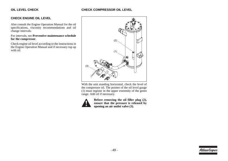
OIL LEVEL CHECK
CHECK ENGINE OIL LEVEL
Also consult the Engine Operation Manual for the oilspecifications, viscosity recommendations and oilchange intervals.For intervals, see Preventive maintenance schedulefor the compressor.Check engine oil level according to the instructions inthe Engine Operation Manual and if necessary top upwith oil.
CHECK COMPRESSOR OIL LEVEL
With the unit standing horizontal, check the level ofthe compressor oil. The pointer of the oil level gauge(1) must register in the upper extremity of the greenrange. Add oil if necessary.
Before removing the oil filler plug (2),ensure that the pressure is released byopening an air outlet valve (3).
(1)
(3)
(2)
- 49 -
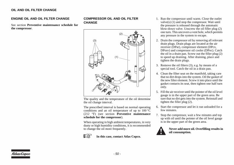
OIL AND OIL FILTER CHANGE
ENGINE OIL AND OIL FILTER CHANGE
See section Preventive maintenance schedule forthe compressor.
COMPRESSOR OIL AND OIL FILTER CHANGE
The quality and the temperature of the oil determinethe oil change interval.The prescribed interval is based on normal operatingconditions and an oil temperature of up to 100 °C(212 °F) (see section Preventive maintenanceschedule for the compressor).When operating in high ambient temperatures, in verydusty or high humidity conditions, it is recommendedto change the oil more frequently.
1. Run the compressor until warm. Close the outlet valve(s) (1) and stop the compressor. Wait until the pressure is released through the automatic blow-down valve. Unscrew the oil filler plug (2) one turn. This uncovers a vent hole, which permits any pressure in the system to escape.
2. Drain the compressor oil by removing all relevant drain plugs. Drain plugs are located at the air receiver (DPar), compressor element (DPcv, DPosv) and compressor oil cooler (DPoc). Catch the oil in a drain pan. Screw out the filler plug (2) to speed up draining. After draining, place and tighten the drain plugs.
3. Remove the oil filters (3), e.g. by means of a special tool. Catch the oil in a drain pan.
4. Clean the filter seat on the manifold, taking care that no dirt drops into the system. Oil the gasket of the new filter element. Screw it into place until the gasket contacts its seat, then tighten one half turn only.
5. Fill the air receiver until the pointer of the oil level gauge is in the upper part of the green area. Be sure that no dirt gets into the system. Reinstall and tighten the filler plug (2).
6. Start the compressor and let it run unloaded for a few minutes.
7. Stop the compressor, wait a few minutes and top up with oil until the pointer of the oil level gauge is in the upper part of the green area.
In this case, contact Atlas Copco.
(1)
(3)
(2)
Never add more oil. Overfilling results inoil consumption.
- 50 -
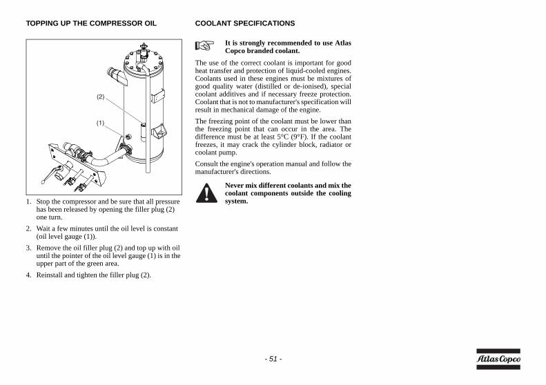
TOPPING UP THE COMPRESSOR OIL
1. Stop the compressor and be sure that all pressure has been released by opening the filler plug (2) one turn.
2. Wait a few minutes until the oil level is constant (oil level gauge (1)).
3. Remove the oil filler plug (2) and top up with oil until the pointer of the oil level gauge (1) is in the upper part of the green area.
4. Reinstall and tighten the filler plug (2).
COOLANT SPECIFICATIONS
The use of the correct coolant is important for goodheat transfer and protection of liquid-cooled engines.Coolants used in these engines must be mixtures ofgood quality water (distilled or de-ionised), specialcoolant additives and if necessary freeze protection.Coolant that is not to manufacturer's specification willresult in mechanical damage of the engine.The freezing point of the coolant must be lower thanthe freezing point that can occur in the area. Thedifference must be at least 5°C (9°F). If the coolantfreezes, it may crack the cylinder block, radiator orcoolant pump.Consult the engine's operation manual and follow themanufacturer's directions.
(1)
(2)
It is strongly recommended to use AtlasCopco branded coolant.
Never mix different coolants and mix thecoolant components outside the coolingsystem.
- 51 -
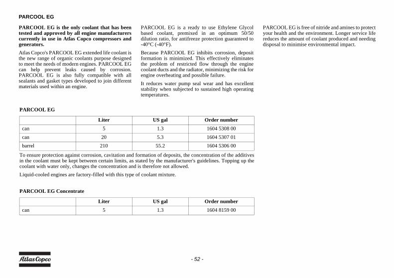
PARCOOL EG
PARCOOL EG is the only coolant that has beentested and approved by all engine manufacturerscurrently in use in Atlas Copco compressors andgenerators.Atlas Copco's PARCOOL EG extended life coolant isthe new range of organic coolants purpose designedto meet the needs of modern engines. PARCOOL EGcan help prevent leaks caused by corrosion.PARCOOL EG is also fully compatible with allsealants and gasket types developed to join differentmaterials used within an engine.
PARCOOL EG is a ready to use Ethylene Glycolbased coolant, premixed in an optimum 50/50dilution ratio, for antifreeze protection guaranteed to-40°C (-40°F).Because PARCOOL EG inhibits corrosion, depositformation is minimized. This effectively eliminatesthe problem of restricted flow through the enginecoolant ducts and the radiator, minimizing the risk forengine overheating and possible failure.It reduces water pump seal wear and has excellentstability when subjected to sustained high operatingtemperatures.
PARCOOL EG is free of nitride and amines to protectyour health and the environment. Longer service lifereduces the amount of coolant produced and needingdisposal to minimise environmental impact.
PARCOOL EG
To ensure protection against corrosion, cavitation and formation of deposits, the concentration of the additivesin the coolant must be kept between certain limits, as stated by the manufacturer's guidelines. Topping up thecoolant with water only, changes the concentration and is therefore not allowed.Liquid-cooled engines are factory-filled with this type of coolant mixture.
PARCOOL EG Concentrate
Liter US gal Order numbercan 5 1.3 1604 5308 00can 20 5.3 1604 5307 01barrel 210 55.2 1604 5306 00
Liter US gal Order numbercan 5 1.3 1604 8159 00
- 52 -
HANDLING PARCOOL EG
PARCOOL EG should be stored at ambienttemperatures, while periods of exposure totemperatures above 35°C (95°F) should beminimized. PARCOOL EG can be stored for aminimum of 5 years in unopened containers withoutany effect on the product quality of performance.PARCOOL EG is compatible with most othercoolants based on ethylene glycol, but you only getthe benefits of 5 years protection when its used on itsown. Exclusive use of PARCOOL EG isrecommended for optimum corrosion protection andsludge control.For simple density-measuring of Ethylene Glycol andPropylene Glycol in general the standard available‘density’ measuring devices are used to measure theconcentration of EG. In case a device is used tomeasure EG, no PG can be measured afterwards as aresult of the difference in the density. More specificmeasurements can be done by the use of arefractometer. This device can measure both EG andPG. A mix of both products will be show unreliableresults!Mixed EG coolants with identical glycol type can bemeasured by use of a refractometer as well as the‘density’ system. The mixed coolants will beconsidered as one product.The use of distilled water is recommended. If youhave exceptionally soft water it would be acceptable,as well. Basically, the engine metals are going tocorrode to some extent no matter what water you use,and hard water will encourage the resulting metalsalts to precipitate.PARCOOL EG comes as a pre-mixed coolant tosafeguard the quality of the complete product.It is recommended that topping up of the coolingsystem is always done with PARCOOL EG.
COOLANT CHECK
In order to guarantee the lifetime and quality of theproduct, thus to optimise engine protection, regularcoolant-condition-analysis is advisable.The quality of the product can be determined by threeparameters:
Visual check• Verify the outlook of the coolant regarding colour
and make sure that no loose particles are floating around.
pH measurement• Check the pH value of the coolant using a pH-
measuring device.• The pH-meter can be ordered from Atlas Copco
with part number 2913 0029 00.• Typical value for EG = 8.6.• If the pH-level is below 7 or above 9.5, the coolant
should be replaced.
Glycol concentration measurement• To optimise the unique engine protection features
of the PARCOOL EG the concentration of the Glycol in the water should be always above 33 vol.%.
• Mixtures with more than 68 vol.% mix ratio in water are not recommended, as this will lead to high engine operating temperatures.
• A refractometer can be ordered from Atlas Copco with part number 2913 0028 00.
TOPPING UP/REPLACING COOLANT
• Verify if the engine cooling system is in a good condition (no leaks, clean,...).
• Check the condition of the coolant.• If the condition of the coolant is outside the limits,
the complete coolant should be replaced (see section Replacing the coolant).
• Always top-up with PARCOOL EG Concentrate / PARCOOL EG.
• Topping up the coolant with water only, changes the concentration of additives and is therefore not allowed.
Never remove the cooling system fillercap while coolant is hot.The system may be under pressure.Remove the cap slowly and only whencoolant is at ambient temperature. Asudden release of pressure from a heatedcooling system can result in personalinjury from the splash of hot coolant.
In case of a mix of different coolantproducts this type of measurementmight provide incorrect values.
- 53 -
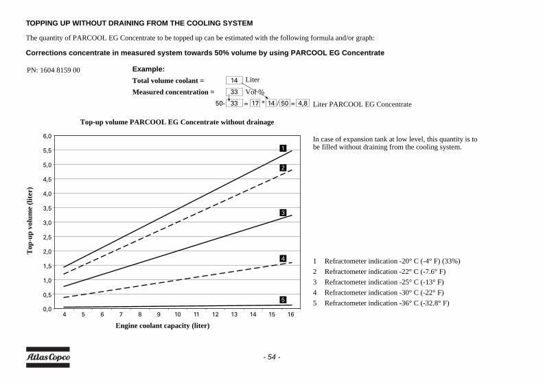
TOPPING UP WITHOUT DRAINING FROM THE COOLING SYSTEM
The quantity of PARCOOL EG Concentrate to be topped up can be estimated with the following formula and/or graph:
Corrections concentrate in measured system towards 50% volume by using PARCOOL EG Concentrate
14
33
33 17 14 50 4,850- = =* /
40,0
0,5
1,0
1,5
2,0
2,5
3,0
3,5
4,0
4,5
5,0
5,5
6,0
5 6 7 8 9 10 11 12 13 14 15 16
1
2
3
4
5
Example:Total volume coolant =Measured concentration =
In case of expansion tank at low level, this quantity is tobe filled without draining from the cooling system.
1 Refractometer indication -20° C (-4° F) (33%)2 Refractometer indication -22° C (-7.6° F)3 Refractometer indication -25° C (-13° F)4 Refractometer indication -30° C (-22° F)5 Refractometer indication -36° C (-32.8° F)
Engine coolant capacity (liter)
Top-up volume PARCOOL EG Concentrate without drainage
Top
-up
volu
me
(lite
r)
PN: 1604 8159 00Liter
Vol %
Liter PARCOOL EG Concentrate
- 54 -
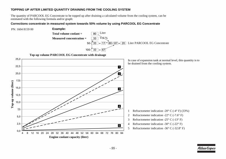
TOPPING UP AFTER LIMITED QUANTITY DRAINING FROM THE COOLING SYSTEM
The quantity of PARCOOL EG Concentrate to be topped up after draining a calculated volume from the cooling system, can be estimated with the following formula and/or graph:Corrections concentrate in measured system towards 50% volume by using PARCOOL EG Concentrate
80
33
33
33
17
67
80 67 2050-
100-
= =* /
=
Example:Total volume coolant =Measured concentration =
In case of expansion tank at normal level, this quantity is tobe drained from the cooling system.
1 Refractometer indication -20° C (-4° F) (33%)2 Refractometer indication -22° C (-7.6° F)3 Refractometer indication -25° C (-13° F)4 Refractometer indication -30° C (-22° F)5 Refractometer indication -36° C (-32.8° F)
Liter
Vol %
Liter PARCOOL EG Concentrate
PN: 1604 8159 00
4 8 12 16 20 24 28 32 36 40 44 48 52 56 60 64 68 72 76 80 840,0
2,5
5,0
7,5
10,0
12,5
15,0
17,5
20,0
22,5
25,0
1
2
3
4
5
Engine coolant capacity (liter)
Top-up volume PARCOOL EG Concentrate with drainage
Top
-up
volu
me
(lite
r)
- 55 -
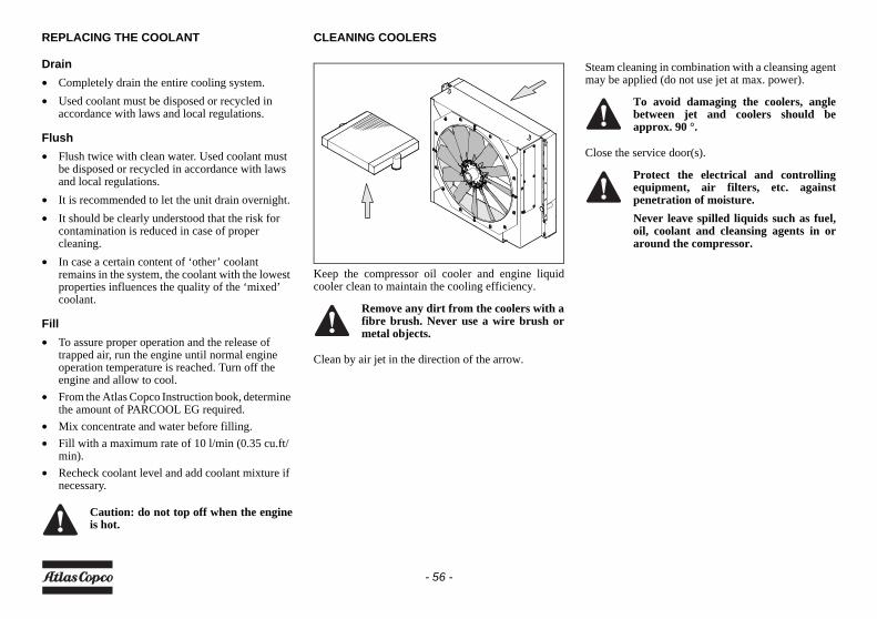
REPLACING THE COOLANT
Drain• Completely drain the entire cooling system.• Used coolant must be disposed or recycled in
accordance with laws and local regulations.
Flush• Flush twice with clean water. Used coolant must
be disposed or recycled in accordance with laws and local regulations.
• It is recommended to let the unit drain overnight.• It should be clearly understood that the risk for
contamination is reduced in case of proper cleaning.
• In case a certain content of ‘other’ coolant remains in the system, the coolant with the lowest properties influences the quality of the ‘mixed’ coolant.
Fill• To assure proper operation and the release of
trapped air, run the engine until normal engine operation temperature is reached. Turn off the engine and allow to cool.
• From the Atlas Copco Instruction book, determine the amount of PARCOOL EG required.
• Mix concentrate and water before filling.• Fill with a maximum rate of 10 l/min (0.35 cu.ft/
min).• Recheck coolant level and add coolant mixture if
necessary.
CLEANING COOLERS
Keep the compressor oil cooler and engine liquidcooler clean to maintain the cooling efficiency.
Clean by air jet in the direction of the arrow.
Steam cleaning in combination with a cleansing agentmay be applied (do not use jet at max. power).
Close the service door(s).
Caution: do not top off when the engineis hot.
Remove any dirt from the coolers with afibre brush. Never use a wire brush ormetal objects.
To avoid damaging the coolers, anglebetween jet and coolers should beapprox. 90 °.
Protect the electrical and controllingequipment, air filters, etc. againstpenetration of moisture.Never leave spilled liquids such as fuel,oil, coolant and cleansing agents in oraround the compressor.
- 56 -
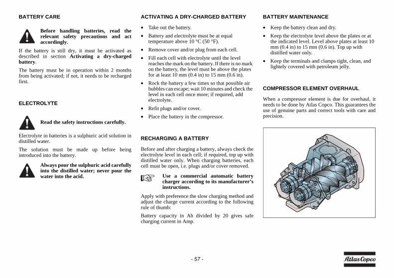
BATTERY CARE
If the battery is still dry, it must be activated asdescribed in section Activating a dry-chargedbattery.The battery must be in operation within 2 monthsfrom being activated; if not, it needs to be rechargedfirst.
ELECTROLYTE
Electrolyte in batteries is a sulphuric acid solution indistilled water.The solution must be made up before beingintroduced into the battery.
ACTIVATING A DRY-CHARGED BATTERY
• Take out the battery.• Battery and electrolyte must be at equal
temperature above 10 °C (50 °F).• Remove cover and/or plug from each cell.• Fill each cell with electrolyte until the level
reaches the mark on the battery. If there is no mark on the battery, the level must be above the plates for at least 10 mm (0.4 in) to 15 mm (0.6 in).
• Rock the battery a few times so that possible air bubbles can escape; wait 10 minutes and check the level in each cell once more; if required, add electrolyte.
• Refit plugs and/or cover.• Place the battery in the compressor.
RECHARGING A BATTERY
Before and after charging a battery, always check theelectrolyte level in each cell; if required, top up withdistilled water only. When charging batteries, eachcell must be open, i.e. plugs and/or cover removed.
Apply with preference the slow charging method andadjust the charge current according to the followingrule of thumb:Battery capacity in Ah divided by 20 gives safecharging current in Amp.
BATTERY MAINTENANCE
• Keep the battery clean and dry.• Keep the electrolyte level above the plates or at
the indicated level. Level above plates at least 10 mm (0.4 in) to 15 mm (0.6 in). Top up with distilled water only.
• Keep the terminals and clamps tight, clean, and lightely covered with petroleum jelly.
COMPRESSOR ELEMENT OVERHAUL
When a compressor element is due for overhaul, itneeds to be done by Atlas Copco. This guarantees theuse of genuine parts and correct tools with care andprecision.
Before handling batteries, read therelevant safety precautions and actaccordingly.
Read the safety instructions carefully.
Always pour the sulphuric acid carefullyinto the distilled water; never pour thewater into the acid. Use a commercial automatic battery
charger according to its manufacturer’sinstructions.
- 57 -
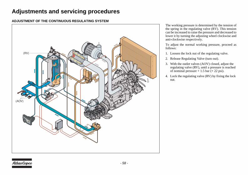
Adjustments and servicing proceduresADJUSTMENT OF THE CONTINUOUS REGULATING SYSTEM
The working pressure is determined by the tension ofthe spring in the regulating valve (RV). This tensioncan be increased to raise the pressure and decreased tolower it by turning the adjusting wheel clockwise andanti-clockwise respectively.To adjust the normal working pressure, proceed asfollows:1. Loosen the lock nut of the regulating valve.2. Release Regulating Valve (turn out).3. With the outlet valves (AOV) closed, adjust the
regulating valve (RV), until a pressure is reached of nominal pressure + 1.5 bar (+ 22 psi).
4. Lock the regulating valve (RV) by fixing the lock nut.
(AOV)
(RV)
- 58 -
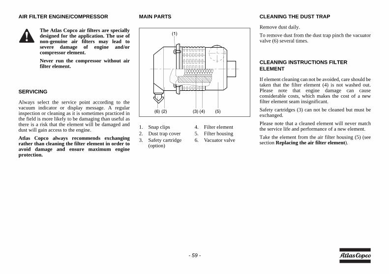
AIR FILTER ENGINE/COMPRESSOR
SERVICING
Always select the service point according to thevacuum indicator or display message. A regularinspection or cleaning as it is sometimes practiced inthe field is more likely to be damaging than useful asthere is a risk that the element will be damaged anddust will gain access to the engine.Atlas Copco always recommends exchangingrather than cleaning the filter element in order toavoid damage and ensure maximum engineprotection.
MAIN PARTS CLEANING THE DUST TRAP
Remove dust daily.To remove dust from the dust trap pinch the vacuatorvalve (6) several times.
CLEANING INSTRUCTIONS FILTER ELEMENT
If element cleaning can not be avoided, care should betaken that the filter element (4) is not washed out.Please note that engine damage can causeconsiderable costs, which makes the cost of a newfilter element seam insignificant.Safety cartridges (3) can not be cleaned but must beexchanged.Please note that a cleaned element will never matchthe service life and performance of a new element.Take the element from the air filter housing (5) (seesection Replacing the air filter element).
The Atlas Copco air filters are speciallydesigned for the application. The use ofnon-genuine air filters may lead tosevere damage of engine and/orcompressor element.Never run the compressor without airfilter element.
1. Snap clips 4. Filter element2. Dust trap cover 5. Filter housing3. Safety cartridge
(option)6. Vacuator valve
(1)
(6) (2) (3) (4) (5)
- 59 -
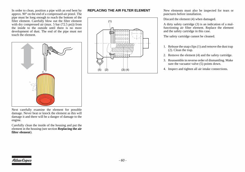
In order to clean, position a pipe with an end bent byapprox. 90° on the end of a compressed-air pistol. Thepipe must be long enough to reach the bottom of thefilter element. Carefully blow out the filter elementwith dry compressed air (max. 5 bar (72.5 psi)) fromthe inside to the outside until there is no moredevelopment of dust. The end of the pipe must nottouch the element.
Next carefully examine the element for possibledamage. Never beat or knock the element as this willdamage it and there will be a danger of damage to theengine.Carefully clean the inside of the housing and put theelement in the housing (see section Replacing the airfilter element).
REPLACING THE AIR FILTER ELEMENT New elements must also be inspected for tears orpunctures before installation.Discard the element (4) when damaged.A dirty safety cartridge (3) is an indication of a mal-functioning air filter element. Replace the elementand the safety cartridge in this case.The safety cartridge cannot be cleaned.
1. Release the snap clips (1) and remove the dust trap (2). Clean the trap.
2. Remove the element (4) and the safety cartridge.3. Reassemble in reverse order of dismantling. Make
sure the vacuator valve (5) points down.4. Inspect and tighten all air intake connections.
(1)
(2)(5) (3) (4)
- 60 -
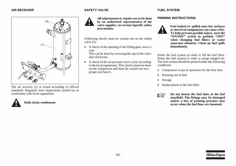
AIR RECEIVER
The air receiver (1) is tested according to officialstandards. Regularly have inspections carried out inconformity with local regulations.
SAFETY VALVE
Following checks must be carried out on the safetyvalve (2):• A check of the opening of the lifting gear, twice a
year.This can be done by screwing the cap of the valve anti-clockwise.
• A check of the set pressure once a year according to the local regulations. This check cannot be done on the compressor and must be carried out on a proper test bench.
FUEL SYSTEM
PRIMING INSTRUCTIONS
Prime the fuel system in order to fill the fuel filter.Prime the fuel system in order to purge trapped air.The fuel system should be primed under the followingconditions:• Compressor is put in operation for the first time• Running out of fuel• Storage• Replacement of the fuel filter
Daily drain condensate.
(1)
(2)All adjustments or repairs are to be doneby an authorized representative of thevalve supplier, see section Specific safetyprecautions.
Fuel leaked or spilled onto hot surfacesor electrical components can cause a fire.To help prevent possible injury, turn the“ON/OFF” switch in position “OFF”when changing fuel filters or waterseparator elements. Clean up fuel spillsimmediately.
Do not loosen the fuel lines at the fuelmanifold. The fittings may be damagedand/or a loss of priming pressure mayoccur when the fuel lines are loosened.
- 61 -
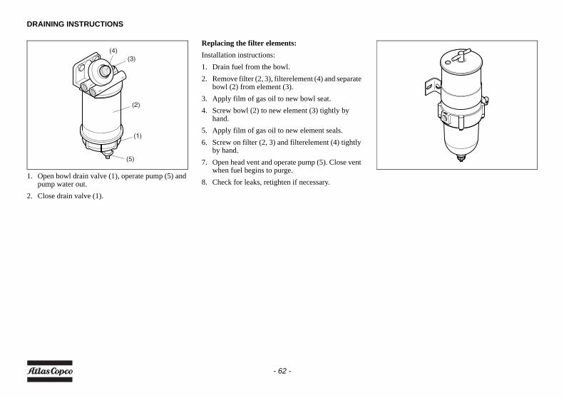
DRAINING INSTRUCTIONS
1. Open bowl drain valve (1), operate pump (5) and pump water out.
2. Close drain valve (1).
Replacing the filter elements:Installation instructions:1. Drain fuel from the bowl.2. Remove filter (2, 3), filterelement (4) and separate
bowl (2) from element (3).3. Apply film of gas oil to new bowl seat.4. Screw bowl (2) to new element (3) tightly by
hand.5. Apply film of gas oil to new element seals.6. Screw on filter (2, 3) and filterelement (4) tightly
by hand.7. Open head vent and operate pump (5). Close vent
when fuel begins to purge.8. Check for leaks, retighten if necessary.
(1)
(4)(3)
(2)
(5)
- 62 -
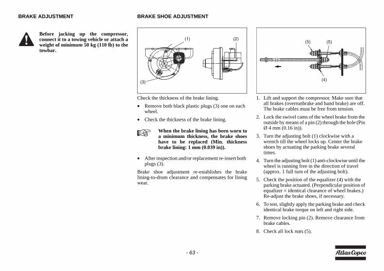
BRAKE ADJUSTMENT BRAKE SHOE ADJUSTMENT
Check the thickness of the brake lining.• Remove both black plastic plugs (3) one on each
wheel.• Check the thickness of the brake lining.
• After inspection and/or replacement re-insert both plugs (3).
Brake shoe adjustment re-establishes the brakelining-to-drum clearance and compensates for liningwear.
1. Lift and support the compressor. Make sure that all brakes (overrunbrake and hand brake) are off. The brake cables must be free from tension.
2. Lock the swivel cams of the wheel brake from the outside by means of a pin (2) through the hole (Pin Ø 4 mm (0.16 in)).
3. Turn the adjusting bolt (1) clockwise with a wrench till the wheel locks up. Center the brake shoes by actuating the parking brake several times.
4. Turn the adjusting bolt (1) anti-clockwise until the wheel is running free in the direction of travel (approx. 1 full turn of the adjusting bolt).
5. Check the position of the equalizer (4) with the parking brake actuated. (Perpendicular position of equalizer = identical clearance of wheel brakes.) Re-adjust the brake shoes, if necessary.
6. To test, slightly apply the parking brake and check identical brake torque on left and right side.
7. Remove locking pin (2). Remove clearance from brake cables.
8. Check all lock nuts (5).
Before jacking up the compressor,connect it to a towing vehicle or attach aweight of minimum 50 kg (110 lb) to thetowbar.
When the brake lining has been worn toa minimum thickness, the brake shoeshave to be replaced (Min. thicknessbrake lining: 1 mm (0.039 in)).
(1) (2)
(3) (4)
(5) (5)
- 63 -
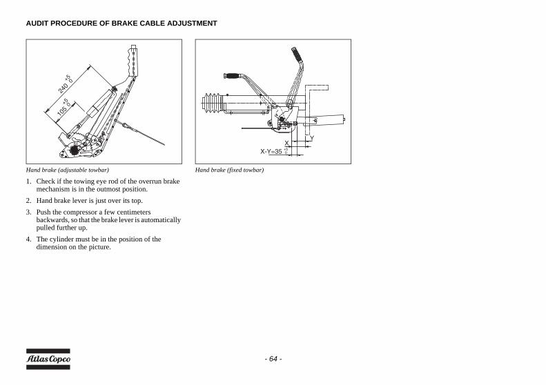
AUDIT PROCEDURE OF BRAKE CABLE ADJUSTMENT
Hand brake (adjustable towbar)
1. Check if the towing eye rod of the overrun brake mechanism is in the outmost position.
2. Hand brake lever is just over its top.3. Push the compressor a few centimeters
backwards, so that the brake lever is automatically pulled further up.
4. The cylinder must be in the position of the dimension on the picture.
Hand brake (fixed towbar)
240+50
105+50
X-Y=35 +50
XY
- 64 -
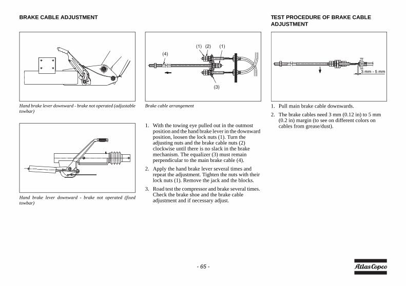
BRAKE CABLE ADJUSTMENT
Hand brake lever downward - brake not operated (adjustabletowbar)
Hand brake lever downward - brake not operated (fixedtowbar)
Brake cable arrangement
1. With the towing eye pulled out in the outmost position and the hand brake lever in the downward position, loosen the lock nuts (1). Turn the adjusting nuts and the brake cable nuts (2) clockwise until there is no slack in the brake mechanism. The equalizer (3) must remain perpendicular to the main brake cable (4).
2. Apply the hand brake lever several times and repeat the adjustment. Tighten the nuts with their lock nuts (1). Remove the jack and the blocks.
3. Road test the compressor and brake several times. Check the brake shoe and the brake cable adjustment and if necessary adjust.
TEST PROCEDURE OF BRAKE CABLE ADJUSTMENT
1. Pull main brake cable downwards.2. The brake cables need 3 mm (0.12 in) to 5 mm
(0.2 in) margin (to see on different colors on cables from grease/dust).
(1) (1)(2)
(3)
(4)
3 mm - 5 mm
- 65 -
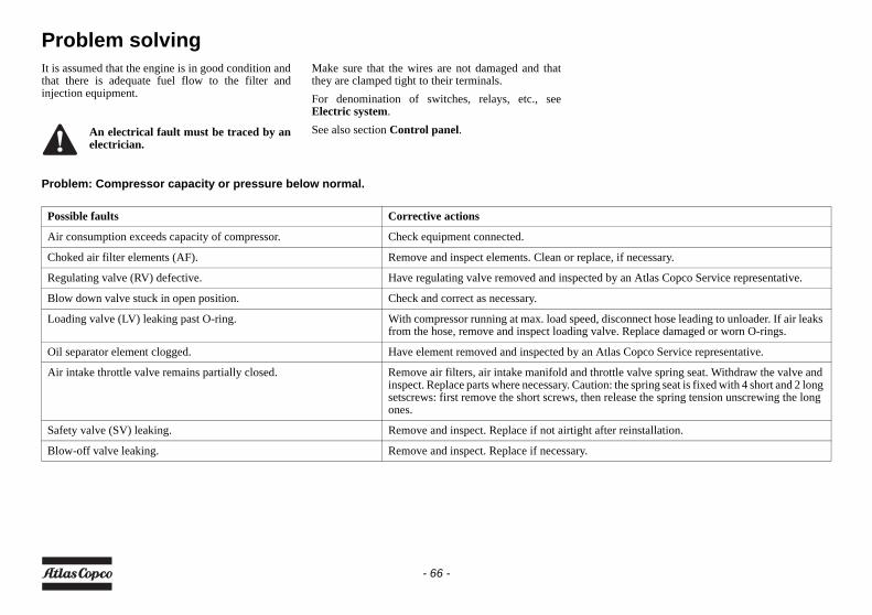
Problem solvingIt is assumed that the engine is in good condition andthat there is adequate fuel flow to the filter andinjection equipment.
Make sure that the wires are not damaged and thatthey are clamped tight to their terminals.For denomination of switches, relays, etc., seeElectric system.See also section Control panel.
Problem: Compressor capacity or pressure below normal.
An electrical fault must be traced by anelectrician.
Possible faults Corrective actions
Air consumption exceeds capacity of compressor. Check equipment connected.
Choked air filter elements (AF). Remove and inspect elements. Clean or replace, if necessary.
Regulating valve (RV) defective. Have regulating valve removed and inspected by an Atlas Copco Service representative.
Blow down valve stuck in open position. Check and correct as necessary.
Loading valve (LV) leaking past O-ring. With compressor running at max. load speed, disconnect hose leading to unloader. If air leaks from the hose, remove and inspect loading valve. Replace damaged or worn O-rings.
Oil separator element clogged. Have element removed and inspected by an Atlas Copco Service representative.
Air intake throttle valve remains partially closed. Remove air filters, air intake manifold and throttle valve spring seat. Withdraw the valve and inspect. Replace parts where necessary. Caution: the spring seat is fixed with 4 short and 2 long setscrews: first remove the short screws, then release the spring tension unscrewing the long ones.
Safety valve (SV) leaking. Remove and inspect. Replace if not airtight after reinstallation.
Blow-off valve leaking. Remove and inspect. Replace if necessary.
- 66 -
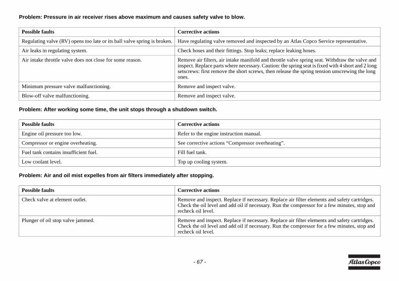
Problem: Pressure in air receiver rises above maximum and causes safety valve to blow.
Problem: After working some time, the unit stops through a shutdown switch.
Problem: Air and oil mist expelles from air filters immediately after stopping.
Possible faults Corrective actions
Regulating valve (RV) opens too late or its ball valve spring is broken. Have regulating valve removed and inspected by an Atlas Copco Service representative.
Air leaks in regulating system. Check hoses and their fittings. Stop leaks; replace leaking hoses.
Air intake throttle valve does not close for some reason. Remove air filters, air intake manifold and throttle valve spring seat. Withdraw the valve and inspect. Replace parts where necessary. Caution: the spring seat is fixed with 4 short and 2 long setscrews: first remove the short screws, then release the spring tension unscrewing the long ones.
Minimum pressure valve malfunctioning. Remove and inspect valve.
Blow-off valve malfunctioning. Remove and inspect valve.
Possible faults Corrective actions
Engine oil pressure too low. Refer to the engine instruction manual.
Compressor or engine overheating. See corrective actions “Compressor overheating”.
Fuel tank contains insufficient fuel. Fill fuel tank.
Low coolant level. Top up cooling system.
Possible faults Corrective actions
Check valve at element outlet. Remove and inspect. Replace if necessary. Replace air filter elements and safety cartridges. Check the oil level and add oil if necessary. Run the compressor for a few minutes, stop and recheck oil level.
Plunger of oil stop valve jammed. Remove and inspect. Replace if necessary. Replace air filter elements and safety cartridges. Check the oil level and add oil if necessary. Run the compressor for a few minutes, stop and recheck oil level.
- 67 -
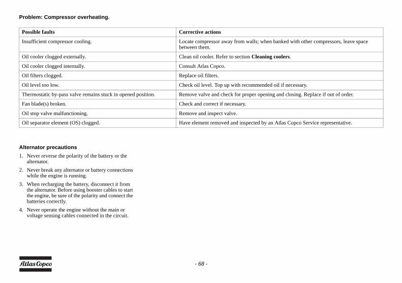
Problem: Compressor overheating.
Alternator precautions1. Never reverse the polarity of the battery or the
alternator.2. Never break any alternator or battery connections
while the engine is running.3. When recharging the battery, disconnect it from
the alternator. Before using booster cables to start the engine, be sure of the polarity and connect the batteries correctly.
4. Never operate the engine without the main or voltage sensing cables connected in the circuit.
Possible faults Corrective actions
Insufficient compressor cooling. Locate compressor away from walls; when banked with other compressors, leave space between them.
Oil cooler clogged externally. Clean oil cooler. Refer to section Cleaning coolers.
Oil cooler clogged internally. Consult Atlas Copco.
Oil filters clogged. Replace oil filters.
Oil level too low. Check oil level. Top up with recommended oil if necessary.
Thermostatic by-pass valve remains stuck in opened position. Remove valve and check for proper opening and closing. Replace if out of order.
Fan blade(s) broken. Check and correct if necessary.
Oil stop valve malfunctioning. Remove and inspect valve.
Oil separator element (OS) clogged. Have element removed and inspected by an Atlas Copco Service representative.
- 68 -
Available optionsSupportA rigid support mounted version for roughconstruction conditions with the possibility to bemounted on a truck. The installation allows the unit tobe put on and taken off the truck daily. It is possibleto handle the unit with a forklift.
Fix height towbar with brakesA fix towbar with integrated parking brake.
Adjustable height towbar with brakesA dual-hinged articulating towbar assembly, withintegrated parking brake.
DIN/NATO/ITA eyeTowing eye according to DIN, NATO or ITAspecification.
Road signalizationA road signalisation option compliant with Europeanregulations. The rear lights are protected by thecanopy or the bumper bar against external damage.
Road signalization USAAdditional side mounted lights to meet NorthAmerican road signalization requirements.
Cold weather package (-10°C (14°F) to -25°C (-13°F))The cold weather package consist of a heater plug,installed in the air-inlet to the engine, a dual approvedvessel (EC/ASME) for which the material is approvedand certified up to -29 °C (-20 °F), and a blow-offvalve on the vessel to minimise the resistance fromthe oil in the vessel when starting at extreme cold-temperatures. Also synthetic compressor oil is used toimprove viscosity at low temperatures.The installation works on battery voltage and comestogether with a timer function. A 5000 Watt (6.7 hp)heater will heat up the engine coolant by means ofconsuming the onboard fuel. (fuel consumption:0.62 l/h (0.16 US gal/h) in operation, water pumpcapacity: +/- 900 l/h (237.8 US gal/h)).
Aftercooler + Water separatorThe aftercooler reduces the discharging airtemperature to ambient + 10 °C (50 °F).On units with a cold weather option a bypass on theaftercooler is standard.
Fine Filter (PD)The fine-filter package completes the after cooleroption. It removes particles and oil content down to0.01 mg/m3 (3.5 oz/1000 cu.ft). Service andreplacement of the filter can be done withoutdismounting other parts or canopy.
Active Coalescing Filter (QD)For improved quality air an additional oil vapour andodour filter is available reducing the oil content to amaximum of 0.003 mg/m3 (1.06 oz/1000 cu.ft). Theactive coal filter pack option can be serviced withoutdismounting other parts or canopy.
- 69 -
ReheaterFor applications with a need for dry unsaturated air orwhere ambient conditions cause risk of freezing toolsa reheater can be installed. The reheater can only beinstalled in combination with the after cooler packand will increase air discharge temperature close toa+60 °C (140 °F).
Spark arrestorThe spark arrestor option prevents burning particlesleaving the exhaust system. This reduces the firehazard in dry conditions to protect the environmentand also enables units to be operated in closedenvironments where there is a fire risk.
Inlet shutdownThe inlet shutdown provides protection to the dieselengine against over speeding caused by failure of theengine regulator, burning oil from the engine sumpdue to overfilling or aspiration of combustible fumesin hazardous environments. The inlet shutdownsystem is fully electronic.
Refinery packageThe refinery package is a combination of the Sparkarrestor and Inlet shutdown options.
Customer colour canopy (1 colour)Special colour will apply on all external canopy partsor all internal parts visible from the outside, andwheel rims. The undercarriage, towbar and frame willbe painted in black.
Customer colour canopy (2 colours)Same to Customer colour (1) option, but with two (2)colours for which the customer will provide details.
Customer colour frame (1 colour)Customer colour for undercarriage, towbar andframe.
COSMOSComprehensive Service and Monitoring System forglobal remote monitoring and fleet management.
FuelXpertThe FuelXpert optimizes the fuel consumption duringoperation at partial load conditions.
- 70 -
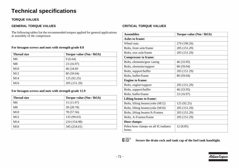
Technical specificationsTORQUE VALUES
GENERAL TORQUE VALUES
The following tables list the recommended torques applied for general applicationsat assembly of the compressor.
For hexagon screws and nuts with strength grade 8.8
For hexagon screws and nuts with strength grade 12.9
CRITICAL TORQUE VALUES
Thread size Torque value (Nm / lbf.ft) M6 9 (6.64)M8 23 (16.97)M10 46 (34.69M12 80 (59.04)M14 125 (92.25)M16 205 (151.29)
Thread size Torque value (Nm / lbf.ft) M6 15 (11.07)M8 39 (28.78)M10 78 (57.56)M12 135 (99.63)M14 210 (154.98)M16 345 (254.61)
Assemblies Torque value (Nm / lbf.ft)Axles to frame:Wheel nuts 270 (199.26)Bolts, front axle/frame 205 (151.29)Bolts, rear axle/frame 205 (151.29)Compressor to frame:Bolts, elements/gear casing 46 (33.95)Bolts, elements/support 80 (59.04)Bolts, support/buffer 205 (151.29)Bolts, buffer/frame 80 (59.04)Engine to frame:Bolts, engine/support 205 (151.29)Bolts, support/buffer 46 (33.95)Bolts, buffer/frame 23 (16.97)Lifting beams to frame:Bolts, lifting beams/yoke (M12) 125 (92.25)Bolts, lifting beams/yoke (M16) 205 (151.29)Bolts, lifting beams/A-Frames 205 (151.29)Bolts, A-Frames/frame 205 (151.29)Hose clamps:Pebra hose clamps on all IC/radiator hoses
12 (8.85)
Secure the drain cock and tank cap of the fuel tank handtight.
- 71 -
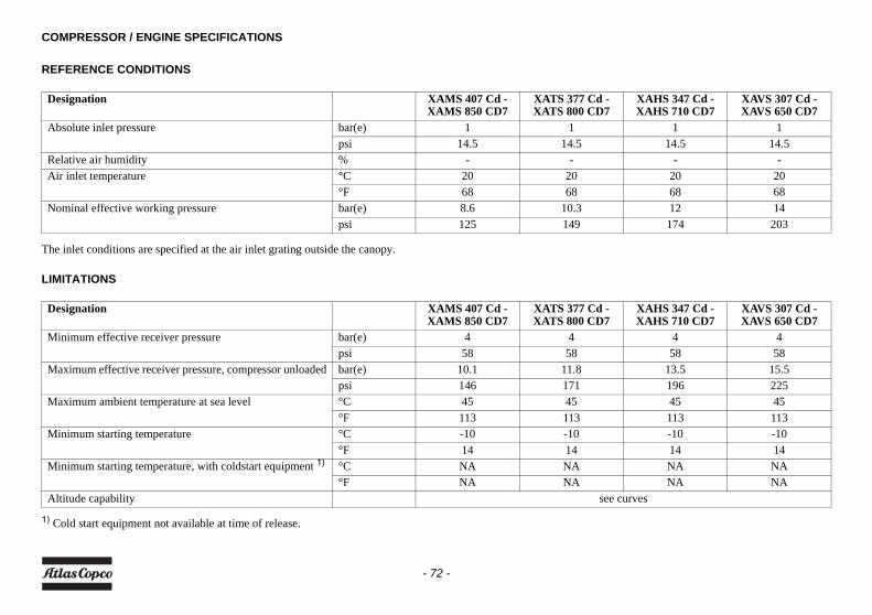
COMPRESSOR / ENGINE SPECIFICATIONS
REFERENCE CONDITIONS
The inlet conditions are specified at the air inlet grating outside the canopy.
LIMITATIONS
1) Cold start equipment not available at time of release.
Designation XAMS 407 Cd - XAMS 850 CD7
XATS 377 Cd - XATS 800 CD7
XAHS 347 Cd - XAHS 710 CD7
XAVS 307 Cd - XAVS 650 CD7
Absolute inlet pressure bar(e) 1 1 1 1psi 14.5 14.5 14.5 14.5
Relative air humidity % - - - -Air inlet temperature °C 20 20 20 20
°F 68 68 68 68Nominal effective working pressure bar(e) 8.6 10.3 12 14
psi 125 149 174 203
Designation XAMS 407 Cd - XAMS 850 CD7
XATS 377 Cd - XATS 800 CD7
XAHS 347 Cd - XAHS 710 CD7
XAVS 307 Cd - XAVS 650 CD7
Minimum effective receiver pressure bar(e) 4 4 4 4psi 58 58 58 58
Maximum effective receiver pressure, compressor unloaded bar(e) 10.1 11.8 13.5 15.5psi 146 171 196 225
Maximum ambient temperature at sea level °C 45 45 45 45°F 113 113 113 113
Minimum starting temperature °C -10 -10 -10 -10°F 14 14 14 14
Minimum starting temperature, with coldstart equipment 1) °C NA NA NA NA°F NA NA NA NA
Altitude capability see curves
- 72 -
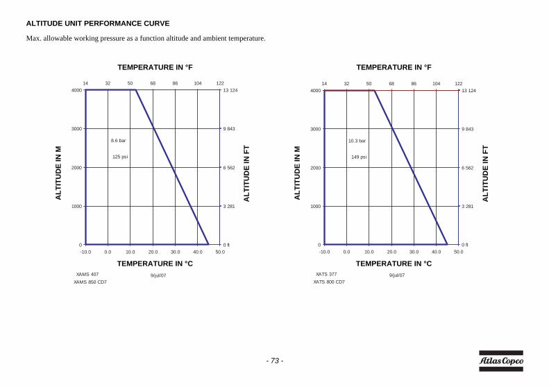
ALTITUDE UNIT PERFORMANCE CURVE
Max. allowable working pressure as a function altitude and ambient temperature.
9/jul/07
3 281
6 562
9 843
13 124
0 ft
14 32 50 68 86 104 122
0
1000
2000
3000
4000
-10.0 0.0 10.0 20.0 30.0 40.0 50.0
XAMS 407 XAMS 850 CD7
125 psi
8.6 bar
9/jul/07
3 281
6 562
9 843
13 124
0 ft
14 32 50 68 86 104 122
0
1000
2000
3000
4000
-10.0 0.0 10.0 20.0 30.0 40.0 50.0
XATS 377 XATS 800 CD7
149 psi
10.3 bar
ALT
ITU
DE
IN M
ALT
ITU
DE
IN F
T
ALT
ITU
DE
IN M
ALT
ITU
DE
IN F
T
TEMPERATURE IN °F TEMPERATURE IN °F
TEMPERATURE IN °C TEMPERATURE IN °C
- 73 -
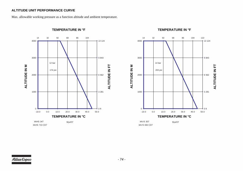
ALTITUDE UNIT PERFORMANCE CURVE
Max. allowable working pressure as a function altitude and ambient temperature.
9/jul/07
3 281
6 562
9 843
13 124
0 ft
14 32 50 68 86 104
0
1000
2000
3000
4000
-10.0 0.0 10.0 20.0 30.0 40.0 50.0
XAHS 347 XAHS 710 CD7
174 psi
12 bar
9/jul/07
3 281
6 562
9 843
13 124
0 ft
14 32 50 68 86 104 122
0
1000
2000
3000
4000
-10.0 0.0 10.0 20.0 30.0 40.0 50.0
XAVS 307 XAVS 650 CD7
203 psi
14 bar
ALT
ITU
DE
IN M
ALT
ITU
DE
IN F
T
ALT
ITU
DE
IN M
ALT
ITU
DE
IN F
T
TEMPERATURE IN °F TEMPERATURE IN °F
TEMPERATURE IN °C TEMPERATURE IN °C
- 74 -
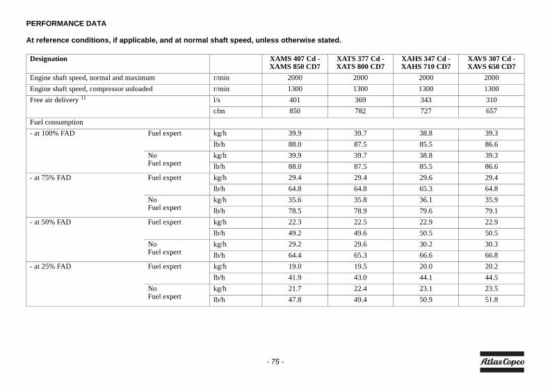
PERFORMANCE DATA
At reference conditions, if applicable, and at normal shaft speed, unless otherwise stated.
Designation XAMS 407 Cd - XAMS 850 CD7
XATS 377 Cd - XATS 800 CD7
XAHS 347 Cd - XAHS 710 CD7
XAVS 307 Cd - XAVS 650 CD7
Engine shaft speed, normal and maximum r/min 2000 2000 2000 2000Engine shaft speed, compressor unloaded r/min 1300 1300 1300 1300Free air delivery 1) l/s 401 369 343 310
cfm 850 782 727 657Fuel consumption- at 100% FAD Fuel expert kg/h 39.9 39.7 38.8 39.3
lb/h 88.0 87.5 85.5 86.6No Fuel expert
kg/h 39.9 39.7 38.8 39.3lb/h 88.0 87.5 85.5 86.6
- at 75% FAD Fuel expert kg/h 29.4 29.4 29.6 29.4lb/h 64.8 64.8 65.3 64.8
No Fuel expert
kg/h 35.6 35.8 36.1 35.9lb/h 78.5 78.9 79.6 79.1
- at 50% FAD Fuel expert kg/h 22.3 22.5 22.9 22.9lb/h 49.2 49.6 50.5 50.5
No Fuel expert
kg/h 29.2 29.6 30.2 30.3lb/h 64.4 65.3 66.6 66.8
- at 25% FAD Fuel expert kg/h 19.0 19.5 20.0 20.2lb/h 41.9 43.0 44.1 44.5
No Fuel expert
kg/h 21.7 22.4 23.1 23.5lb/h 47.8 49.4 50.9 51.8
- 75 -
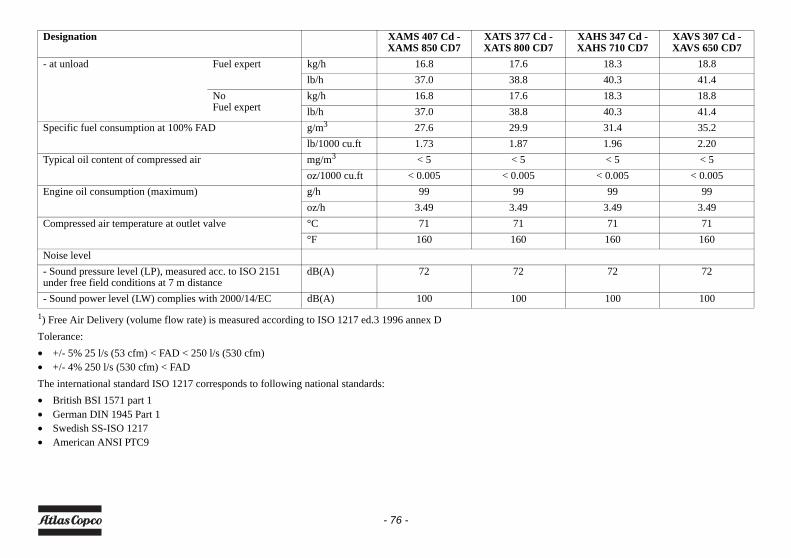
1) Free Air Delivery (volume flow rate) is measured according to ISO 1217 ed.3 1996 annex DTolerance:• +/- 5% 25 l/s (53 cfm) < FAD < 250 l/s (530 cfm)• +/- 4% 250 l/s (530 cfm) < FADThe international standard ISO 1217 corresponds to following national standards:• British BSI 1571 part 1• German DIN 1945 Part 1• Swedish SS-ISO 1217• American ANSI PTC9
- at unload Fuel expert kg/h 16.8 17.6 18.3 18.8lb/h 37.0 38.8 40.3 41.4
No Fuel expert
kg/h 16.8 17.6 18.3 18.8lb/h 37.0 38.8 40.3 41.4
Specific fuel consumption at 100% FAD g/m3 27.6 29.9 31.4 35.2lb/1000 cu.ft 1.73 1.87 1.96 2.20
Typical oil content of compressed air mg/m3 < 5 < 5 < 5 < 5oz/1000 cu.ft < 0.005 < 0.005 < 0.005 < 0.005
Engine oil consumption (maximum) g/h 99 99 99 99oz/h 3.49 3.49 3.49 3.49
Compressed air temperature at outlet valve °C 71 71 71 71°F 160 160 160 160
Noise level- Sound pressure level (LP), measured acc. to ISO 2151 under free field conditions at 7 m distance
dB(A) 72 72 72 72
- Sound power level (LW) complies with 2000/14/EC dB(A) 100 100 100 100
Designation XAMS 407 Cd - XAMS 850 CD7
XATS 377 Cd - XATS 800 CD7
XAHS 347 Cd - XAHS 710 CD7
XAVS 307 Cd - XAVS 650 CD7
- 76 -
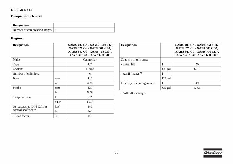
DESIGN DATA
Compressor element
Engine
1) With filter change.
DesignationNumber of compression stages 1
Designation XAMS 407 Cd - XAMS 850 CD7,XATS 377 Cd - XATS 800 CD7,XAHS 347 Cd - XAHS 710 CD7,XAVS 307 Cd - XAVS 650 CD7
Make CaterpillarType C7Coolant LiquidNumber of cylinders 6Bore mm 110
in 4.33Stroke mm 127
in 5.00Swept volume l 7.2
cu.in 439.3Output acc. to DIN 6271 at normal shaft speed
kW 186hp 249
- Load factor % 80
Designation XAMS 407 Cd - XAMS 850 CD7,XATS 377 Cd - XATS 800 CD7,XAHS 347 Cd - XAHS 710 CD7,XAVS 307 Cd - XAVS 650 CD7
Capacity of oil sump:- Initial fill l 26
US gal 6.87- Refill (max.) 1) l
US galCapacity of cooling system l 49
US gal 12.95
- 77 -
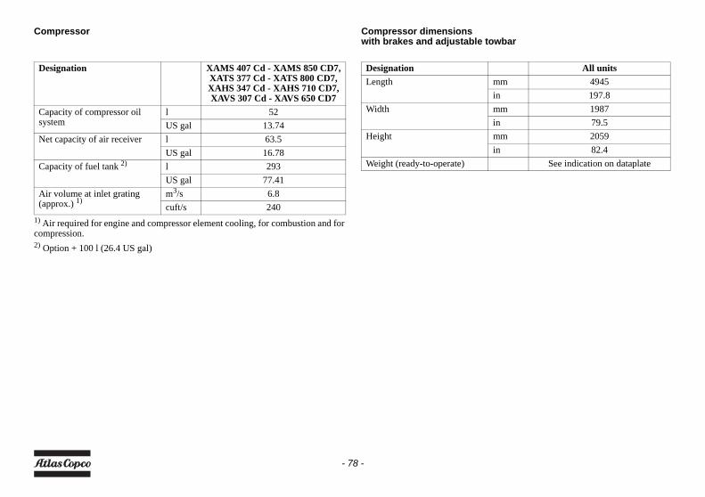
Compressor
1) Air required for engine and compressor element cooling, for combustion and forcompression.2) Option + 100 l (26.4 US gal)
Compressor dimensionswith brakes and adjustable towbar
Designation XAMS 407 Cd - XAMS 850 CD7,XATS 377 Cd - XATS 800 CD7,XAHS 347 Cd - XAHS 710 CD7,XAVS 307 Cd - XAVS 650 CD7
Capacity of compressor oil system
l 52US gal 13.74
Net capacity of air receiver l 63.5US gal 16.78
Capacity of fuel tank 2) l 293US gal 77.41
Air volume at inlet grating (approx.) 1)
m3/s 6.8cuft/s 240
Designation All unitsLength mm 4945
in 197.8Width mm 1987
in 79.5Height mm 2059
in 82.4Weight (ready-to-operate) See indication on dataplate
- 78 -
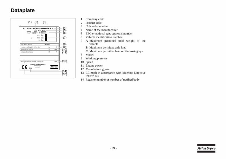
Dataplate1 Company code2 Product code3 Unit serial number4 Name of the manufacturer5 EEC or national type approval number6 Vehicle identification number7 A Maximum permitted total weight of the
vehicleB Maximum permitted axle loadC Maximum permitted load on the towing eye
8 Model9 Working pressure10 Speed11 Engine power12 Manufacturing year13 CE mark in accordance with Machine Directive
89/392 EC14 Register number or number of notified body
(1) (2) (3)
(4)(5)(6)
(7)
(8)(9)
(10)(11)
(12)
(14)(13)
- 79 -
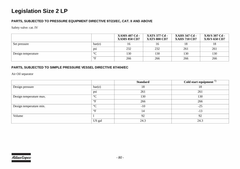
Legislation Size 2 LPPARTS, SUBJECTED TO PRESSURE EQUIPMENT DIRECTIVE 97/23/EC, CAT. II AND ABOVE
Safety valve: cat. IV
PARTS, SUBJECTED TO SIMPLE PRESSURE VESSEL DIRECTIVE 87/404/EC
Air Oil separator
XAMS 407 Cd - XAMS 850 CD7
XATS 377 Cd - XATS 800 CD7
XAHS 347 Cd - XAHS 710 CD7
XAVS 307 Cd - XAVS 650 CD7
Set pressure bar(e) 16 16 18 18psi 232 232 261 261
Design temperature °C 130 130 130 130°F 266 266 266 266
Standard Cold start equipment 1)
Design pressure bar(e) 18 18psi 261 261
Design temperature max. °C 130 130°F 266 266
Design temperature min. °C -10 -25°F 14 -13
Volume l 92 92US gal 24.3 24.3
- 80 -
PARTS, SUBJECTED TO CAT. I AND COVERED BY THE MACHINE DIRECTIVE 89/392/EC
All other parts
PARTS, SUBJECTED TO ART. I, PARAGRAPH 3.3
All other parts
- 81 -
DisposalGENERAL
When developing products and services, Atlas Copcotries to understand, address, and minimize thenegative environmental effects that the products andservices may have, when being manufactured,distributed, and used, as well as at their disposal.Recycling and disposal policy are part of thedevelopment of all Atlas Copco products. AtlasCopco company standards determine strictrequirements.Selecting materials the substantial recyclability, thedisassembly possibilities and the separability ofmaterials and assemblies are considered as well as theenvironmental perils and dangers to health during therecycling and disposal of the unavoidable rates of notrecyclable materials.Your Atlas Copco compressor consists for the mostpart of metallic materials, that can be remelted insteelworks and smelting works and that is thereforealmost infinite recyclable. The plastic used islabelled; sorting and fractioning of the materials forrecycling in the future is forseen.
DISPOSAL OF MATERIALS
Dispose contaminated substances and materialseparately, according to local applicableenvironmental legislations.Before dismantling a machine at the end of itsoperating lifetime drain all fluids and dispose ofaccording the applicable local disposal regulations. Remove the batteries. Do not throw batteries into thefire (explosion risk) or into the residual waste.Separate the machine into metal, electronics, wiring,hoses, insulation and plastic parts. Dispose all components according to the applicabledisposal regulations.Remove spilled fluid mechanically; pick up the restwith absorbing agent (for example sand, sawdust) anddispose it according the applicable local disposalregulations. Do not drain into the sewage system orsurface water.
This concept can only succeed with yourhelp. Support us by disposingprofessionally. By assuring a correctdisposal of the product you help toprevent possible negative consequencesfor environment and health, that canoccur with an inappropriate wastehandling.Recycling and re-usage of material helpsto preserve natural resources.
- 82 -
Maintenance Log
Compressor .......................................................................................... Customer ...............................................................................................
Serial number........................................................................................ ................................................................................................................
Service hours Maintenance action Date By initials
- 83 -

Notes:
- 84 -


www.atlascopco.com
Atlas Copco Instruction Manual