Embed Size (px)
Citation preview

111
Atlas V Secondary Payload Carriers –2006Atlas V Secondary Payload Carriers –2006
EELV Secondary PayloadAccommodations
CubeSat Workshop
April 10, 2008
Jake Szatkowski, PhD. ULA, Denver CO USA

222
SP IssuesSP Issues
• Primary payload’s lack willingness to fly SPs
• Launch vehicle team has a risk avers mind-set
• SPs electrically quiescent from encapsulation thru primary mission
• Need to establish enveloping SP specs for Mission Analysis
– Enveloping environmental standard, separation shock limits, Loads
• Need for defined SP qualification methodology and certification
• Include lessons learned from STP-1
– Need to certify sep systems
– Must do “test-like-you-fly” in the SIL (for new H/W)
– Simplify avionics electrical I/F for recurring integration
– Simplify the integration process (time and money)

333
Atlas Rideshare OptionsAtlas Rideshare Options• Dual Spacecraft System (DSS), 1500-3500 lb
• Integrated Payload Carrier (IPC), 400 lb ea.– Supports Larger Secondary Payloads
– ESPA Flight Proven on STP-1 (Feb ‘07)
– Being used for NASA LCROSS mission
• Small Class Carriers – Type-C Carrier (TCC), 35 lb
– Aft Bulkhead Carrier (ABC), ~300 lb
– Secondary Payload Carrier (SPC), 220 lb
• X-ternal Payload Carrier (XPC)– Supports Sub-orbital Flight Test, ~1500 lb
Requirements
ESPA
IPC
XPC
TCC
DSS

444
DSS for large class Dual PayloadsDSS for large class Dual Payloads
• DSS consists of a qualified structure in a 4M fairing
• Sep system at the midline frees the SP for inside the carrier
• ILC late '09
AMPG10_F080101_02
PLF SepPLF Sep
Primary Satellite SepPrimary Satellite Sep
AMPG10_XXXX
DSS Sep
AMPG10_XXXX
DSS Sep
SecondarySatellite SepSecondary
Satellite Sep
In flightIn flight

555
IPC / ESPA Mission ConceptIPC / ESPA Mission Concept• STP-1 released a primary and 5 SPs
– Orbital Express (primary) with MidStar-1 at 492km circular, 46 deg incl
– NPSAT1, STPSat-1, CFE, FalconSat-3 at 560km circular, 35.4 deg incl
• Most commercial launches are GTO
– Approx. at 27 deg w/ a retrograde orbit that is either + or – a ½ deg.
– Perigee is nominally 185 nm up to 300 nm
– Apogee is GTO up to 100k nm
– Upper Stage do degrade over time.
– Tend to circularize at perigee & gradually lower till extinction.
• Currently Funded by AFRL to simplify the integration process.
666
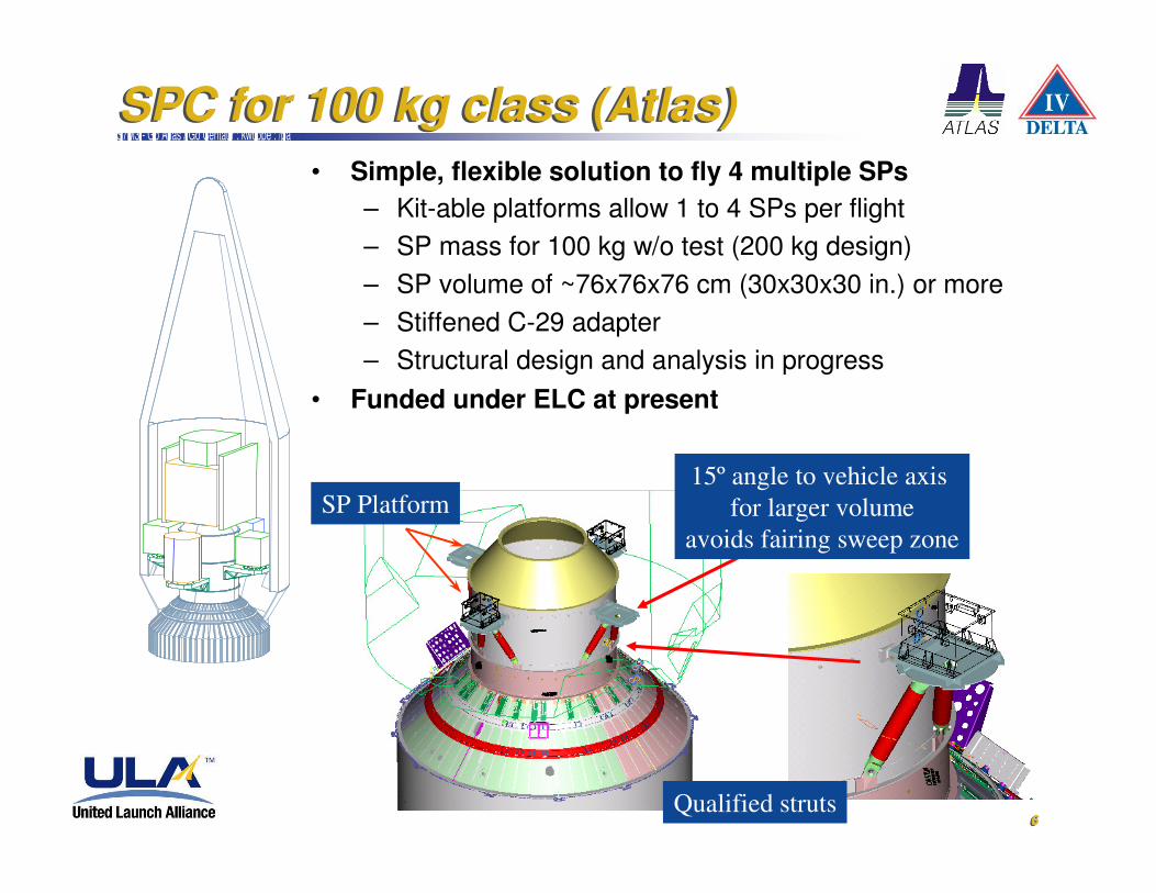
SPC for 100 kg class (Atlas)SPC for 100 kg class (Atlas)I-DEAS Master Series 7m3 : ATLAS MS7M3 - Go Atlas / Go Centaur : kwcope : /pa
• Simple, flexible solution to fly 4 multiple SPs
– Kit-able platforms allow 1 to 4 SPs per flight
– SP mass for 100 kg w/o test (200 kg design)
– SP volume of ~76x76x76 cm (30x30x30 in.) or more
– Stiffened C-29 adapter
– Structural design and analysis in progress
• Funded under ELC at present
SP Platform15º angle to vehicle axis
for larger volume
avoids fairing sweep zone
Qualified struts
777
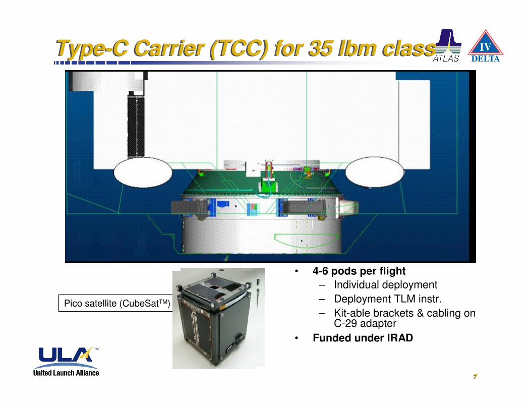
Type-C Carrier (TCC) for 35 lbm classType-C Carrier (TCC) for 35 lbm class
Pico satellite (CubeSatTM)
• 4-6 pods per flight
– Individual deployment
– Deployment TLM instr.
– Kit-able brackets & cabling on C-29 adapter
• Funded under IRAD

888
Avionics-SEIP Reallocation for SPs (SPIP)Avionics-SEIP Reallocation for SPs (SPIP)
MDU
CENTAURFORWARDADAPTER
P12
BLACK SOLID LINES DENOTE LV GENERIC HARNESS
GRAY SOLID LINES DENOTE MISSION PECULIAR I/F HARNESS (PLA PROVIDED)
SC TO LVINTERFACE PLANE
(SIP)
SEIP
SEPARATION PLANE
C-29 PAYLOAD ADAPTER
C-13 PAYLOAD ADAPTER
PRIMARY SV
Umb
Sec PL
Sec PL
Sec PL
Sec PL
Interface capability usageby Secondary PL(s) isextremely intrusive toPrimary SV critical M/Phardware and schedule
ORCA’s URCU
CENTAURFORWARDADAPTER
P12
BLACK SOLID LINES DENOTE LV GENERIC HARNESS
GRAY SOLID LINES DENOTE MISSION PECULIAR I/F HARNESS (PLA PROVIDED)
SC TO LVINTERFACE PLANE
(SIP)
SEPARATION PLANE
SEIP
C-29 PAYLOAD ADAPTER
C-13 PAYLOAD ADAPTER
PRIMARY SV
Sec PL Sec PL
Sec PL
Primary Ord Cmd’s (12 become 8/4)Secondary Ord Cmd’s (12 becomes 8/4)
Primary Ord Cmd’s(8)Secondary Ord Cmd’s(8){
Primary SVOrdnance
Commands
Primary Ord Cmd’s(4)
Secondary Ord Cmd’s(4)
SecondarySV
OrdnanceCommands
Sec PL
}
P12 P12B
P13
P13B
ORCA’s
BLACK DOTTED LINES DENOTES MODIFIED LV GENERIC HARNESS
GREEN SOLID LINES DENOTES Ppod SECONDARY I/F HARNESS (PRIMARY DEPLOYMENT I/F)
BLUE SOLID LINES DENOTES Ppod SECONDARY I/F HARNESS (PRIMARY DEPLOYMENT I/F)
Most likely requires thatexisting P12 and P13 shellsizes be reduced to provide
sufficient panel space foradded connectors
S/C support is thru the Standard Electrical Interface
Panel (SEIP) on the Centaur Forward Adapter (CFA)
Creates a “Christmas-tree” harness w/ SPs
Block Change will “T” separate a portion of the EELV S/C Interface Spec (SIS) to support SPs with the application of “pig-tail” cables.
Causes “no change” to the primary S/C harness.
Creates the Small Payload Interface Panel (SPIP)
Current
New Block-change

999
SP System IntegrationSP System Integration
NLT L-16 mo
SP Mission
Feasibility
Study
NLT L-10 mo
SP Mission
Service
Award
NLT L-9 mo
Combined
Mission
Integration
Kick Off
TransportEncapsulated
Payloads To VIF
Roll Vehicle to Launch Pad
Launch
Encapsulated P/L Hoist & Mating Ops
Primary
PayloadReceipt at Launch Site
PLF Receipt
Encapsulate Payloads
Start SP integration at Lnch Site, NLTL-1.5 mo
SP Match-mate, & I/F testing in SIL for new H/W
Integrated Launch Vehicle Testing
Primary PayloadIntegration
SPs Receipt for Integration TLYFNLT L-6 mo(L-3 for reflights)
(NLT – No Later Than)
L-24 moPrimary Mission ATP
NLT L-13 mo
Payload
Compatibility
Certification

101010
SP System Integration Lab (SIL) SP System Integration Lab (SIL)
• To run a SP Integration verification we need to test
– from the ground system to the SP,
– from the Atlas Vehicle Avionics to the SP
– track and analyze TLM from the SP
• The CFA provides all the SP standard cabling
– electrical I/Fs (power, A/B sequencing) using a CRCU
– MDU provides TLM data interleave via 422 I/F
• Avionics-SIM provides A/B events
• Gnd H/W interfaces provides power & umbilical
• CCLS will sequence thru ground tests
• ADMS provides operator stations
– TLM monitoring, TLM archive data
• PCs to port customer SP sw for testing
SPIntegration
I/F Chassis
CCLSComputer
Controlled Launch Set
CentaurForward Adapter
(CFA)DET
ADMSADMS PCPC
A/B cables
(customer stations)
CRCU
422
FTINUElectrical
Equivalent
Uplink/Downlink
(100 baseT)
The SP-SIL can help you get ready to fly

111111
Sample of Mission Margins Sample of Mission Margins
• Mission opportunities are available
• Most are GTO, for now
• Carriers are being developed now for ILC in '09