Embed Size (px)
Citation preview
Atmospheric Instrumentation M. D. Eastin
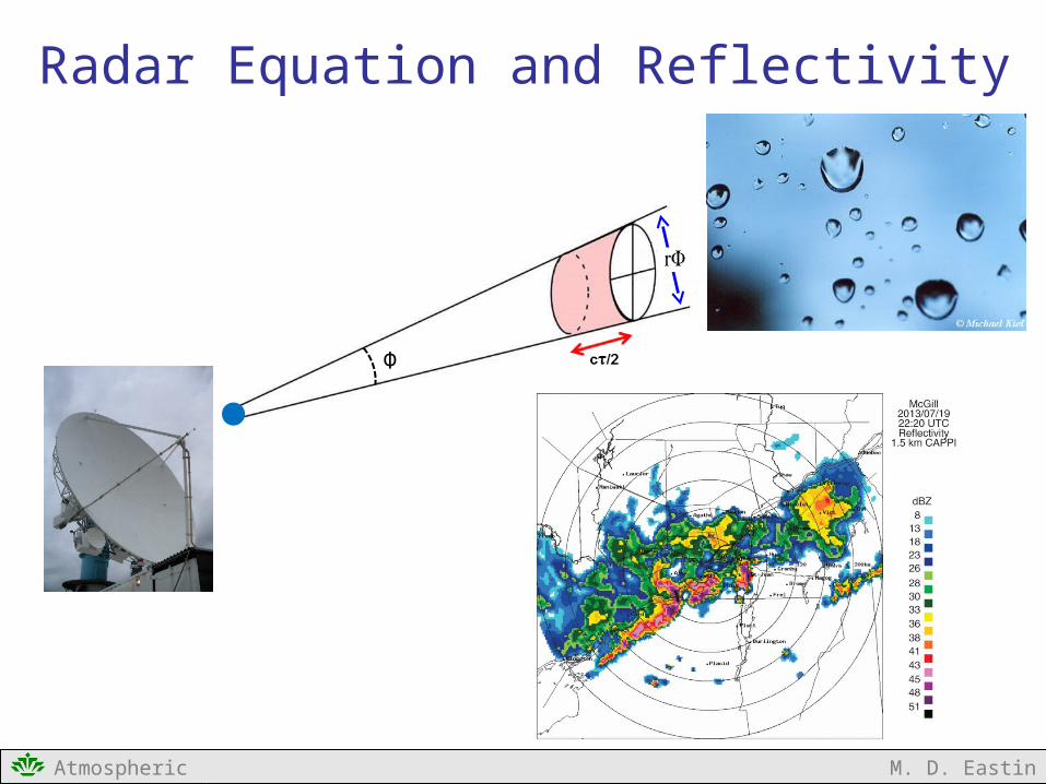
Radar Equation and Reflectivity
Φ
Atmospheric Instrumentation M. D. Eastin
Outline
Radar Equation and Reflectivity
• Basic Approach to Radar Equation Development
• Solitary Target• Power incident on target• Power scattered back toward the radar• Power received by the antenna
• Distributed (Multiple) Targets
• Distributed (Multiple) Weather Targets
• Equivalent Radar Reflectivity Factor

Atmospheric Instrumentation M. D. Eastin
Radar Equation DevelopmentBasic Approach: Conceptual Development
Radar Observation: The “return echo power” scattered back from “targets” can provideuseful information about the target’s characteristics
( size / number of aircraft → enemy bomber raid? ) ( size / number of raindrops → reflectivity → storm structure )
Radar Equation: Provides a relationship between (1) the return echo power, (2) thetarget’s characteristics, and (3) unique antenna/radar characteristics
Basic development is common to all radars!
Solitary Target: Develop radar equation for a single target (i.e., one raindrop)
1. Determine the transmitted power flux density incident on the target
2. Determine the power flux density scattered back toward the radar
3. Determine the amount of back-scattered power collected by the radar antenna
Distributed Targets: Expand to allow for multiple targets with the volume
Atmospheric Instrumentation M. D. Eastin
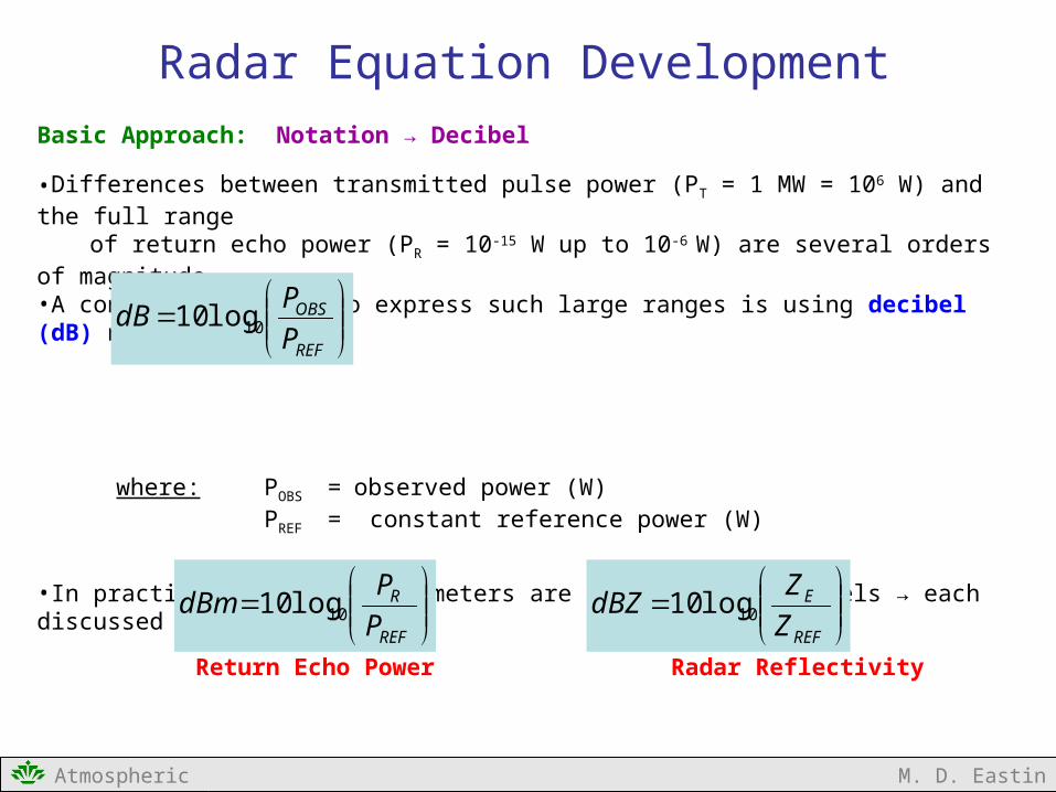
Radar Equation DevelopmentBasic Approach: Notation → Decibel
•Differences between transmitted pulse power (PT = 1 MW = 106 W) and the full rangeof return echo power (PR = 10-15 W up to 10-6 W) are several orders of magnitude
•A convenient method to express such large ranges is using decibel (dB) notation:
where: POBS = observed power (W) PREF = constant reference power (W)
•In practice, two radar parameters are expressed in decibels → each discussed later in detail
Return Echo Power Radar Reflectivity
PREF = 1 ×10⁻³ W ZREF = 1 mm6 m-3
= 1 mW = Z for one 1-mm drop
REF
OBS
P
PdB 10log10
REF
R
P
PdBm 10log10
REF
E
Z
ZdBZ 10log10
Atmospheric Instrumentation M. D. Eastin
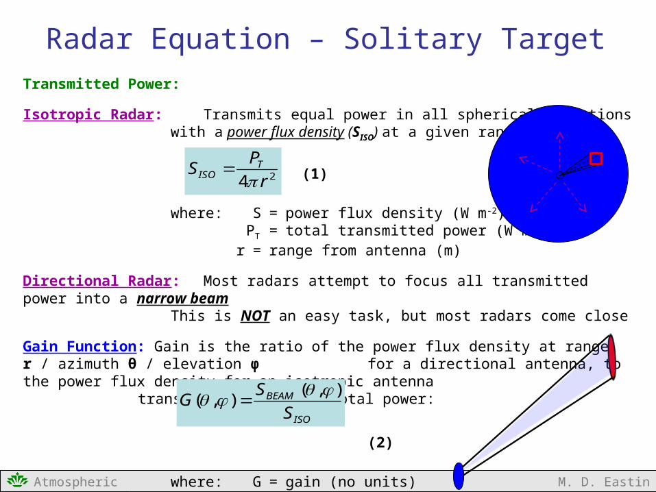
Radar Equation – Solitary TargetTransmitted Power:
Isotropic Radar: Transmits equal power in all spherical directionswith a power flux density (SISO) at a given range:
(1)
where: S = power flux density (W m-2) PT = total transmitted power (W m-2)
r = range from antenna (m)
Directional Radar: Most radars attempt to focus all transmitted power into a narrow beamThis is NOT an easy task, but most radars come close
Gain Function: Gain is the ratio of the power flux density at range r / azimuth θ / elevation φ for a directional antenna, to the power flux density for an isotropic antennatransmitting the same total power:
(2)
where: G = gain (no units)
24 r
PS TISO
ISO
BEAM
S
SG
),(),(

Transmitted Power:
Gain Function: If we combine (1) and (2), we can solve for the beam’s power flux density:
(3)
No radar emits a perfect conical beam due to manufacturing imperfections in the waveguide and antenna → gain functions are unique to each radar
Main Lobe: Maximum gain on the order of 40-50 dB ** (see two slides prior)Side Lobes: Maximum gain of 4 dB (most are less than 0 dB)Back Lobe: Maximum gain less than 0 dB
Effective beam width (Θ): Defined at the location equivalent to 3 dB less than the peak gain of the main lobe → narrower beam widths are desired
Atmospheric Instrumentation M. D. Eastin
Radar Equation – Solitary Target
24 r
GPS TBEAM
Main LobeSide Lobes
BackLobe
3 dBΘ

Transmitted Power:
Antenna Size: Since effective beam width and main lobe powerare linked to antenna size, so is the gain:
(4)
where: AE = effective antenna area (m2)λ = transmitting wavelength (m)
Large Antenna → Large gain→ Large wavelengths→ Small beam widths→ Desired→ Budget?
Small Antenna → Small gain→ Small wavelengths→ Large beam widths→ Less desired→ Budget?
Atmospheric Instrumentation M. D. Eastin
Radar Equation – Solitary Target
2
4
EAG
10 cm
3 cm

Atmospheric Instrumentation M. D. Eastin
Radar Equation – Solitary TargetProblems Associated with Side Lobes:
•Any return echo from a side lobe is interpreted as a weak return from the main lobewhich effectively produces a three-dimensional expansion of the storm size
Horizontal Spreading of Storm Vertical Spreading of Storm Top

Atmospheric Instrumentation M. D. Eastin
Radar Equation – Solitary TargetPrimary Method to Minimize Side Lobes:
• Use a parabolic antenna
• Parabolic antennas allow for “tapered illumination” which minimize the transmitted power flux density along the edges
• Effects of Tapered Illumination:
1. Reduction of side lobe returns2. Reduction of maximum gain3. Increased beam width
•The last two are undesirable, but in practice, parabolic antennasreduce side lobes by ~80%, reduce gain by less than 5%, and
increase beam width by less than 25% → acceptable compromise
Beam GeometryOutgoing Power
Flux Density

Atmospheric Instrumentation M. D. Eastin
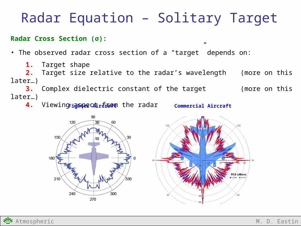
Radar Equation – Solitary TargetRadar Cross Section (σ):
• Defined as the ratio of the power flux density scattered by the target in the direction of the antenna to the power flux density incident on the target (both measured at the target radius)
(5)
NOTE: SBACK is not measured at a radius SBACK is measured at the radar
• For practical purposes, the radar cross section isredefined as the power flux density received at a point on a spherical surface
(6)
rS
rS
BEAM
BACK )(
BEAM
R
S
Sr 24
Radar TransmittedPower Flux Density
Target BackscatterPower Flux Density
Atmospheric Instrumentation M. D. Eastin
Radar Equation – Solitary TargetRadar Cross Section (σ):
• The observed radar cross section of a “target” depends on:
1. Target shape2. Target size relative to the radar’s wavelength (more on this later…)3. Complex dielectric constant of the target (more on this later…)4. Viewing aspect from the radar
Fighter Aircraft Commercial Aircraft

Atmospheric Instrumentation M. D. Eastin
Radar Equation – Solitary TargetReceived Power at the Antenna:
• Recall from before:
(3) (4)
(6)
• Substituting (3) into (6):
(7)
• We can now define the received power (PR) at the antenna as:
(8)
4216 r
PGS TR
ERR ASP
24 r
GPS TBEAM
BEAM
R
S
Sr 24
2
4
EAG Power flux density
incident on targetGain – Antenna size
relationship
Radar cross section
Power flux densityof a target’s backscatter received at the antenna
Power flux density incident on a target

Atmospheric Instrumentation M. D. Eastin
Radar Equation – Solitary TargetReceived Power at the Antenna:
• Substituting (4) and (7) into (8) yields:
(9)
•After re-arranging:
•Written in terms of antenna area:
43
22
64 r
PGP RR
Radar equation for a single isolated target
(e.g. an airplane, bird, or one raindrop)
422
364
1
rGPP TR
Constant RadarCharacteristics
TargetCharacteristics
42
2
4
1
r
APP ETR
Constant RadarCharacteristics
TargetCharacteristics
What do theseequations tell us
about radar returnsfrom a single target?

Atmospheric Instrumentation M. D. Eastin
Radar Equation – Distributed TargetsDistributed Target:
• A target consisting of multiple scattering objects• All raindrops intercepted by a single radar pulse
Contributing Region:
• Total volume containing all objects from whichback-scattered return power arrives backat the radar simultaneously
Single Pulse Volume:
•First, assuming the main lobe pulse is cylindrical at large distances (>10 km) from the radar
• Volume of contributing region for a single pulse:
(10)
2
2
r
AP Cross-sectional area
of a pulse at radius (r) and angular beam width (Φ)
Φ
2
cLP
Contributing lengthof a pulse transmitted
for duration (τ)
822
222
rcrcLAV PPP
Atmospheric Instrumentation M. D. Eastin
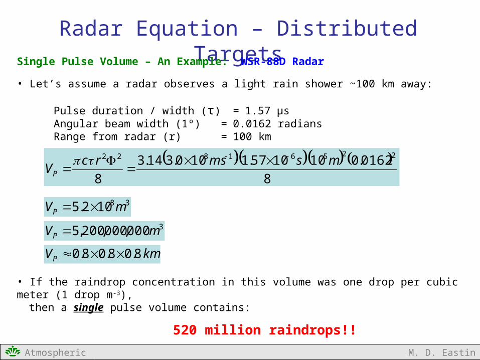
Radar Equation – Distributed TargetsSingle Pulse Volume – An Example: WSR-88D Radar
• Let’s assume a radar observes a light rain shower ~100 km away:
Pulse duration / width (τ) = 1.57 μs Angular beam width (1º) = 0.0162 radians Range from radar (r) = 100 km
• If the raindrop concentration in this volume was one drop per cubic meter (1 drop m-3),then a single pulse volume contains:
520 million raindrops!!
8
0162.0101057.1100.314.3
8
22561822 msmsrcVP
38102.5 mVP 3000,000,200,5 mVP
kmVP 8.08.08.0

Atmospheric Instrumentation M. D. Eastin
Radar Equation – Distributed TargetsAccounting for Gain Shape:
• The gain function’s main lobe is not truly cylindrical(but it’s a good first approximation)
• Rather, the main lobe exhibits a Gaussian shapewhereby it maximizes along the beam axis anddecreases with angular distance from the axis
• Accounting for such shape can be accomplishedby incorporating a simple geometric correction →
(11)factor [ 1 / 2ln(2) ] into the pulse volume definition
Mean Radar Cross Section (σAVG):
• Each radar pulse volume can contain an array of various sized /shaped objects• Their collective cross section is a mean of all individual cross sections in the pulse volume• For simplicity, we will use the standard algebraic mean
(12)j
jAVG
Main Lobe
Θ
2ln16
22
rcVP
8
22
rcVP

Atmospheric Instrumentation M. D. Eastin
Radar Equation – Distributed TargetsReceived Power at the Antenna:
• We can now multiple the radar equation for a single target (9) by the pulse volume (11) andthen substitute the mean radar cross section (12) to arrive at a radar equation describingthe received power at the antenna for a distribution of targets within any pulse volume…
(9) (11)(12)
…and after re-arranging:
(13)
2222
2)2ln(1024 rGP
cP AVG
TR
ConstantRadar
CharacteristicsTarget
Characteristics
j
jAVG 2ln16
22
rcVP
43
22
64 r
PGP RR

Atmospheric Instrumentation M. D. Eastin
Radar Equation – Distributed Weather TargetsModifying our Radar Equation for Weather Targets:
• Meteorologists are interested in weather targets, so we can develop a special form of the distributed radar equation for typical collections of precipitation particles
• Airports are interesting in tracking local aircraft, so special forms of the radar equationcan be developed to better detect commercial and recreational aircraft
•Militaries are interested in tracking aircraft and ships (friendly and enemy), so special forms of the radar equation can be developed to better detect (stealth) aircraft and military ships.
Four tasks must be completed:
1. Understand the impact of a radar pulse’s electric field on a water particle2. Find the radar cross section for a single precipitation particle3. Find the total radar cross section for the entire contributing region4. Obtain the average radar reflectivity from all particles in that region

Atmospheric Instrumentation M. D. Eastin
Radar Equation – Distributed Weather TargetsFirst Assumption: All targets are spheres!
Small Raindrops = Spheres Ice Crystals = Variety of shapes Large raindrops= Ellipsoids Graupel / Hail = Variety of shapes

Atmospheric Instrumentation M. D. Eastin
Radar Equation – Distributed Weather TargetsSecond Assumption: All targets are small!
•If targets are sufficiently small compared to the wavelength of the transmitted radar pulse,then the backscatter can be described by Rayleigh Scattering Theory
Types of scattering:
RayleighMieOptical
How small? Why Raleigh scattering?
• Target radius less than λ/20
• Since the target particles are much smaller than the variability associated with the radar pulse’s
electric-field (a sine wave), then we can assumethe electric-field across the particle will be uniform

Atmospheric Instrumentation M. D. Eastin
Radar Equation – Distributed Weather TargetsImpact of a Radar Pulse’s Electric Field on a Water Particle:
• The radar pulse (and its associated electric field) will induce an electric dipole within any homogeneous dielectric sphere (i.e., a water drop or ice sphere)
Induced electric dipole vector (EDP) → Direction is the same as the pulse’s electric field→ Magnitude is the product of the incident electric
field and the polarization of the sphere
where: ε0 = permittivity in a vacuum K = dielectric constant for water / ice D = diameter of a spherical particle (m) EBEAM = amplitude of incident electric field (W)
• The sphere then scatters that portion of the electric field equivalent to the dipole magnitudesuch that the electric backscatter received at the radar is defined by:
OR (14)
2
30 BEAM
DP
EKDE
r
pER
02
r
EDKE BEAMR 2
32
2

Atmospheric Instrumentation M. D. Eastin
Radar Equation – Distributed Weather TargetsRadar Cross Section of a Single Small Dielectric Sphere:
• The relationship between the power flux density (S) and the electric field (E) for both thetransmitted pulse and that received back at the radar are related via:
(15)
• Combining (14) and (15) with (6) we get the radar cross section for a single sphere:...
(6) (14)
…and after re-arranging:
(16)
BEAM
R
S
Sr 24
2
2
BEAM
R
BEAM
R
E
E
S
S
r
EDKE BEAMR 2
32
2
4
625
DK
What does this equation
tell us about radar returnsfrom a single weather target?

Atmospheric Instrumentation M. D. Eastin
Radar Equation – Distributed Weather TargetsRadar Cross Section for Multiple Small Dielectric Spheres:
• Following the same methods as before, we can combine (12) and (16) such that…
(12) (16)
…the mean radar cross section for an array of spherical water particles:
(17)
• We can now define a mean radar reflectivity factor for all spherical water particlesin the radar pulse volume:
(18) OR
j
jAVG 4
625
DK
j
jj
jAVG DK 64
25
j
jDZ 6 dDDDNZ 6
0
Equation 3.1in the Fabry text

Atmospheric Instrumentation M. D. Eastin
Radar Equation – Distributed Weather TargetsReceived Power at the Antenna:
• Using (18), we can now substitute the mean radar cross section for an array of sphericalwater particles (17) into the generic radar equation for distributed targets (13) to arrive ata radar equation describing the received power at the antenna for a distribution of weathertargets within any pulse volume…
(13) (17) (18)
…and after re-arranging:
(19)
2
2
2
223
)2ln(1024 r
ZKGPcP TR
ConstantRadar
CharacteristicsTarget
Characteristics
22
222
)2ln(1024 r
PGcP AVGTR
jjAVG D
K 64
25
jjDZ 6

Atmospheric Instrumentation M. D. Eastin
What is the Dielectric Constant (K)?
• A measure of the scattering and absorption properties of a medium (water or ice) wheninteracting with an electromagnetic field (a radar beam pulse)
where: Permittivity in a medium
Permittivity in a vacuum
Dielectric Constant Values – Water Targets
LIQUID: K2 = 0.930 (spheres)
ICE: K2 = 0.176 (solid spheres) K2 = 0.202 (snow flakes)
•Since K2 varies as a function of particle shape and water phase, we would need to knowthe shape and phase of every water particle present in the pulse volume!
No way to obtain this information!We must make an assumption about the K2 value!
2
1
r
rK
0
1
r
Equivalent Radar Reflectivity Factor
Atmospheric Instrumentation M. D. Eastin
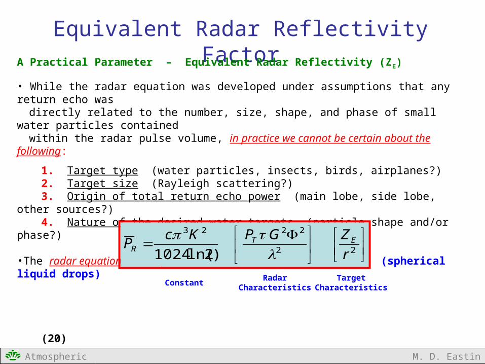
Equivalent Radar Reflectivity FactorA Practical Parameter – Equivalent Radar Reflectivity (ZE)
• While the radar equation was developed under assumptions that any return echo wasdirectly related to the number, size, shape, and phase of small water particles containedwithin the radar pulse volume, in practice we cannot be certain about the following:
1. Target type (water particles, insects, birds, airplanes?)2. Target size (Rayleigh scattering?)3. Origin of total return echo power (main lobe, side lobe, other sources?)4. Nature of the desired water targets (particle shape and/or phase?)
•The radar equation used in practice assumes constant K2 = 0.93 (spherical liquid drops)
(20)
22
2223
)2ln(1024 r
ZGPKcP ETR
ConstantRadar
CharacteristicsTarget
Characteristics

Atmospheric Instrumentation M. D. Eastin
Equivalent Radar Reflectivity FactorA Practical Parameter – Equivalent Radar Reflectivity (ZE)
• Finally, we can solve the practical radar equation for distributed weather targets (20) forthe equivalent radar reflectivity (ZE
(21)
•The equivalent reflectivity factor (ZE) is computed by the radar processing software basedon (1) measured return echo power (PR), (2) range (r) – determined from the time betweenpulse transmission and echo return, and (3) known constants and radar characteristics
•The computed ZE are then transformed into decibel notation for display:
(22)
ConstantRadar
CharacteristicsTarget
Characteristics
222
2
23
)2ln(1024rP
GPKcZ R
TE
3610 /1log10
mmm
ZdBZ E

Atmospheric Instrumentation M. D. Eastin
Equivalent Radar Reflectivity FactorIMPORTANT – Decibel Notation (dB) and Equivalent Radar Reflectivity (ZE)
• Equation (21) provides ZE in units of m6 / m3
• Equation (22) provides dBZ using ZE in units of mm6 / m3 (so the fraction is unit-less)
The computed ZE from (21) must be multiplied by 1018 to obtain a correct dBZ!
(21)
(22)
222
2
23
)2ln(1024rP
GPKcZ R
TE
3610 /1log10
mmm
ZdBZ E

Atmospheric Instrumentation M. D. Eastin
Radar Equation DevelopmentIMPORTANT – Review of Assumptions:
1. All precipitation particles are homogeneous dielectric spheres with diameterssmall compared to the radar wavelength (the Rayleigh approximation)
2. All particles are evenly spread through the contributing region
3. The equivalent reflectivity factor (ZE) is uniform throughout the contributingregion and constant during the time period required to obtain the mean valueof the received power
4. All particles have the same dielectric constant – assumed to be liquid water spheres
5. The main lobe of the radar pulse is adequately described by a Gaussian function
6. Microwave attenuation between the radar and the target is negligible
7. Multiple scattering is negligible
8. The incident and backscattered pulses are linearly polarized.

Atmospheric Instrumentation M. D. Eastin
Radar Equation DevelopmentIMPORTANT – Validity of the Rayleigh Approximation?
Valid:
Invalid:
λ = 10 cmRaindrops: 0.01 – 0.5 cm (all rain)Ice crystals: 0.01– 3 cm (all snow)Ice stones: 0.5 – 2.0 cm (small to moderate hail)
λ = 3 cmRaindrops: 0.01 – 0.5 cm (all rain)Ice crystals: 0.01– 0.5 cm (single crystals)Ice stones: 0.1 - 0.5 cm (graupel)
λ = 10 cmIce stones: > 2 cm (large hail)
λ = 3 cmIce crystals: > 0.5 cm (snowflakes)Ice stones: > 0.5 cm (hail and large graupel)
Atmospheric Instrumentation M. D. Eastin
Summary
Radar Equation and Reflectivity
• Basic Approach to Radar Equation Development
• Solitary Target• Power incident on target• Power scattered back toward the radar• Power received by the antenna
• Distributed (Multiple) Targets
• Distributed (Multiple) Weather Targets
• Equivalent Radar Reflectivity Factor

Atmospheric Instrumentation M. D. Eastin
References
Atlas , D., 1990: Radar in Meteorology, American Meteorological Society, 806 pp.
Crum, T. D., R. L. Alberty, and D. W. Burgess, 1993: Recording, archiving, and using WSR-88D data. Bulletin of the American Meteorological Society, 74, 645-653.
Doviak, R. J., and D. S. Zrnic, 1993: Doppler Radar and Weather Observations, Academic Press, 320 pp.
Fabry, F., 2015: Radar Meteorology Principles and Practice, Cambridge University Press, 256 pp.
Reinhart, R. E., 2004: Radar for Meteorologists, Wiley- Blackwell Publishing, 250 pp.