Embed Size (px)
Citation preview
Atom 5 dBi CPE User Manual
August 2017
Version 1.1
ii
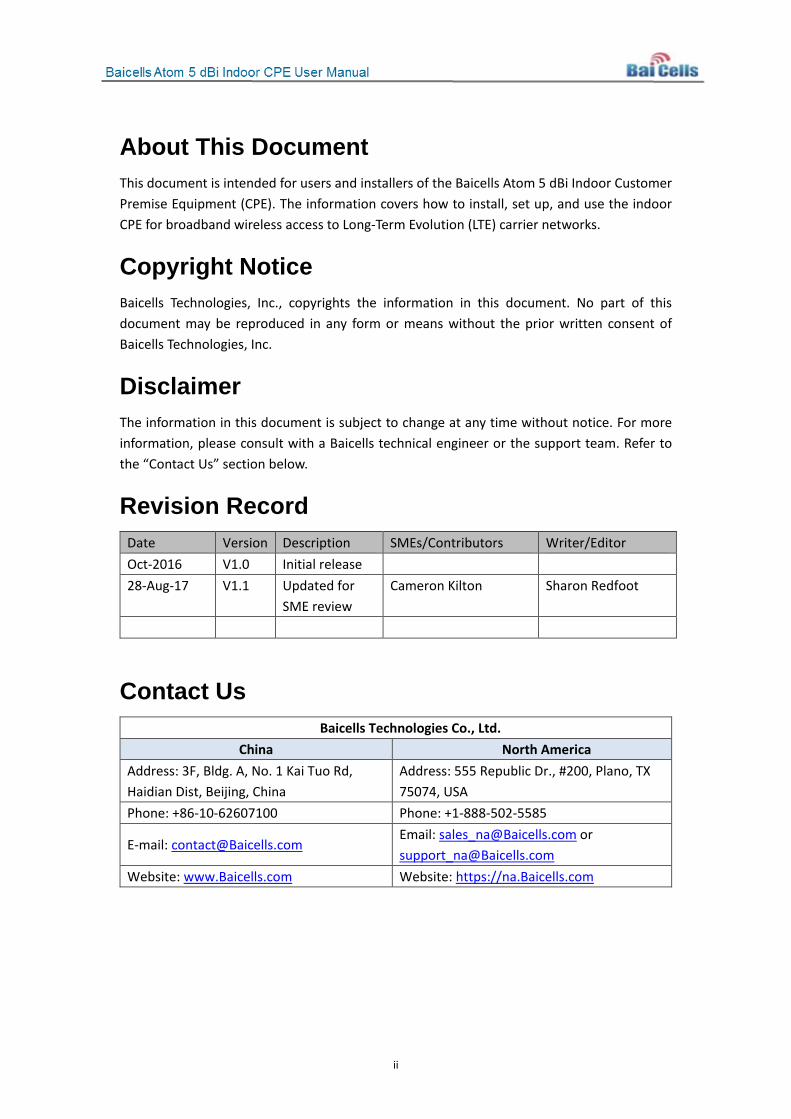
About This Document This document is intended for users and installers of the Baicells Atom 5 dBi Indoor Customer Premise Equipment (CPE). The information covers how to install, set up, and use the indoor CPE for broadband wireless access to Long-Term Evolution (LTE) carrier networks.
Copyright Notice Baicells Technologies, Inc., copyrights the information in this document. No part of this document may be reproduced in any form or means without the prior written consent of Baicells Technologies, Inc.
Disclaimer The information in this document is subject to change at any time without notice. For more information, please consult with a Baicells technical engineer or the support team. Refer to the “Contact Us” section below.
Revision Record Date Version Description SMEs/Contributors Writer/Editor Oct-2016 V1.0 Initial release 28-Aug-17 V1.1 Updated for
SME review Cameron Kilton Sharon Redfoot
Contact Us Baicells Technologies Co., Ltd.
China North America Address: 3F, Bldg. A, No. 1 Kai Tuo Rd, Haidian Dist, Beijing, China
Address: 555 Republic Dr., #200, Plano, TX 75074, USA
Phone: +86-10-62607100 Phone: +1-888-502-5585
E-mail: [email protected] Email: [email protected] or [email protected]
Website: www.Baicells.com Website: https://na.Baicells.com
iii
Table of Contents 1. INTRODUCTION ....................................................................................................................... 1
2. PARTS LIST............................................................................................................................... 2
3. DESCRIPTION .......................................................................................................................... 3
4. INSTALLATION ......................................................................................................................... 7
5. BASIC CONFIGURATION ........................................................................................................... 8
APPENDIX A: SPECIFICATIONS ........................................................................................................ 14
A-1: BASIC SPECIFICATIONS ....................................................................................................................... 14 A-2: RF SPECIFICATIONS........................................................................................................................... 14 A-3: SOFTWARE SPECIFICATIONS ................................................................................................................ 14 A-4: DEVICE MANAGEMENT SPECIFICATIONS ............................................................................................... 15 A-5: ENVIRONMENTAL SPECIFICATIONS ....................................................................................................... 15
APPENDIX B: FAQS ......................................................................................................................... 16
List of Figures FIGURE 1-1: BAICELLS BROADBAND WIRELESS ACCESS SYSTEM .............................................................................. 1 FIGURE 3-1: ATOM 5 DBI INDOOR CPE ............................................................................................................. 3 FIGURE 3-2: BACK INTERFACES ........................................................................................................................ 3 FIGURE 3-3: LED INDICATORS .......................................................................................................................... 4 FIGURE 3-4: SIDES OF CPE UNIT ...................................................................................................................... 6 FIGURE 5-1: LOG IN TO CPE GUI ..................................................................................................................... 8 FIGURE 5-2: CHANGE ACCOUNT INFORMATION ................................................................................................... 8 FIGURE 5-3: NETWORK MODE ........................................................................................................................ 9 FIGURE 5-4: LTE SETTINGS ............................................................................................................................. 9 FIGURE 5-5: SCAN MODE ............................................................................................................................. 10 FIGURE 5-6: PCI LOCK SETTINGS .................................................................................................................... 11 FIGURE 5-7: BAND/FREQUENCY PREFERRED SETTINGS ....................................................................................... 11 FIGURE 5-8: APN MANAGEMENT SETTINGS .................................................................................................... 12
List of Tables TABLE 2-1: PARTS ......................................................................................................................................... 2 TABLE 3-1: LEDS AND INTERFACES ................................................................................................................... 4 TABLE 3-2: SPECIAL STATUS INDICATORS ............................................................................................................ 5 TABLE 3-3: SIDE BUTTONS AND CARD SLOT ........................................................................................................ 6 TABLE 5-1: APN MANAGEMENT SETTINGS ...................................................................................................... 12
1
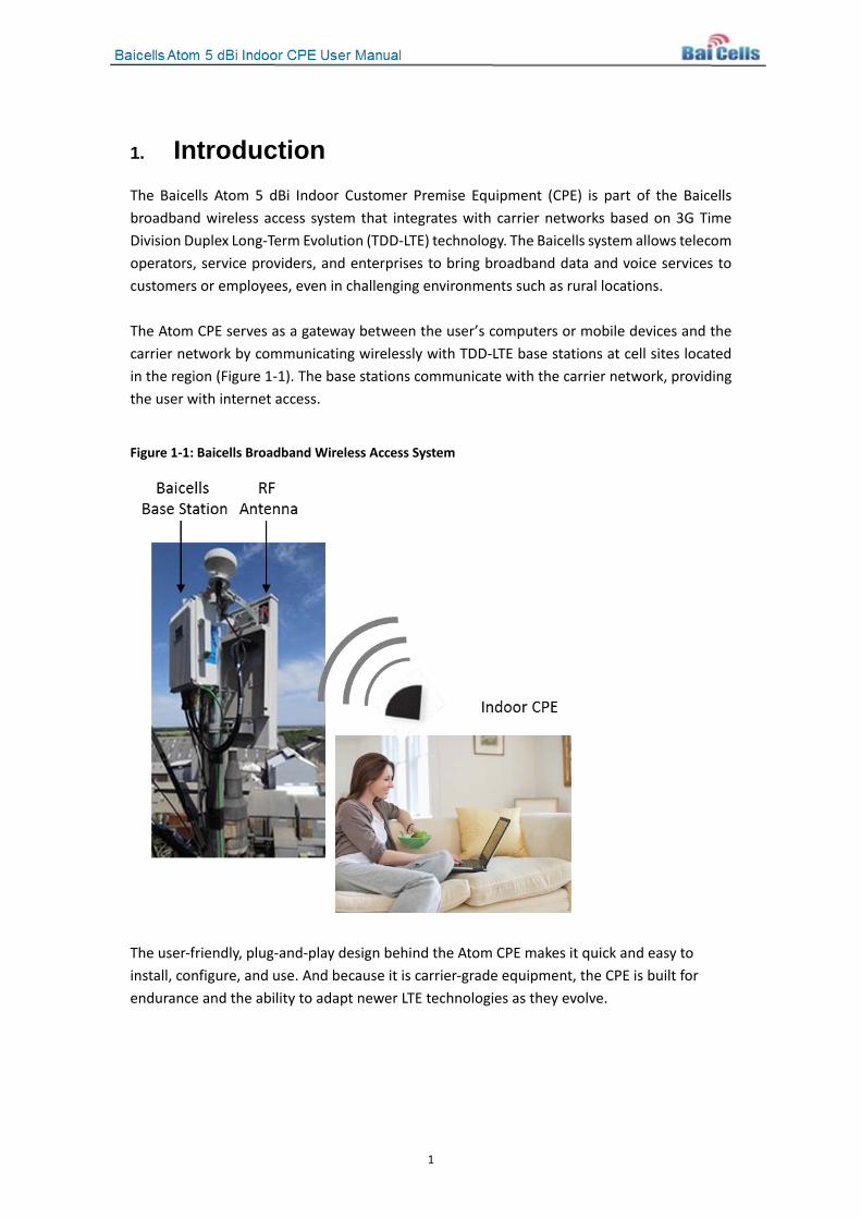
1. Introduction The Baicells Atom 5 dBi Indoor Customer Premise Equipment (CPE) is part of the Baicells broadband wireless access system that integrates with carrier networks based on 3G Time Division Duplex Long-Term Evolution (TDD-LTE) technology. The Baicells system allows telecom operators, service providers, and enterprises to bring broadband data and voice services to customers or employees, even in challenging environments such as rural locations. The Atom CPE serves as a gateway between the user’s computers or mobile devices and the carrier network by communicating wirelessly with TDD-LTE base stations at cell sites located in the region (Figure 1-1). The base stations communicate with the carrier network, providing the user with internet access.
Figure 1-1: Baicells Broadband Wireless Access System
The user-friendly, plug-and-play design behind the Atom CPE makes it quick and easy to install, configure, and use. And because it is carrier-grade equipment, the CPE is built for endurance and the ability to adapt newer LTE technologies as they evolve.
2
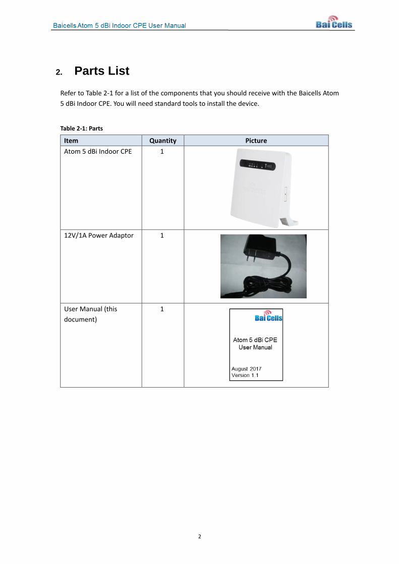
2. Parts List Refer to Table 2-1 for a list of the components that you should receive with the Baicells Atom 5 dBi Indoor CPE. You will need standard tools to install the device.
Table 2-1: Parts
Item Quantity Picture Atom 5 dBi Indoor CPE 1
12V/1A Power Adaptor 1
User Manual (this document)
1
3
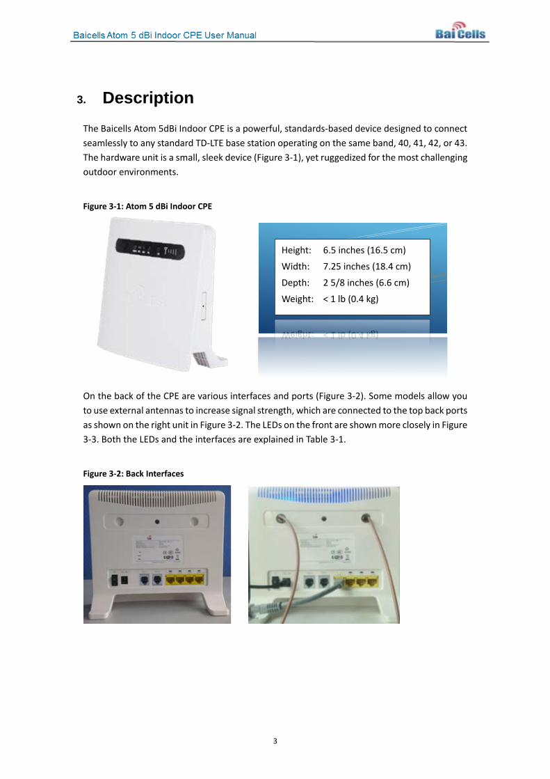
3. Description The Baicells Atom 5dBi Indoor CPE is a powerful, standards-based device designed to connect seamlessly to any standard TD-LTE base station operating on the same band, 40, 41, 42, or 43. The hardware unit is a small, sleek device (Figure 3-1), yet ruggedized for the most challenging outdoor environments.
Figure 3-1: Atom 5 dBi Indoor CPE
On the back of the CPE are various interfaces and ports (Figure 3-2). Some models allow you to use external antennas to increase signal strength, which are connected to the top back ports as shown on the right unit in Figure 3-2. The LEDs on the front are shown more closely in Figure 3-3. Both the LEDs and the interfaces are explained in Table 3-1.
Figure 3-2: Back Interfaces
Height: 6.5 inches (16.5 cm)
Width: 7.25 inches (18.4 cm)
Depth: 2 5/8 inches (6.6 cm)
Weight: < 1 lb (0.4 kg)
4
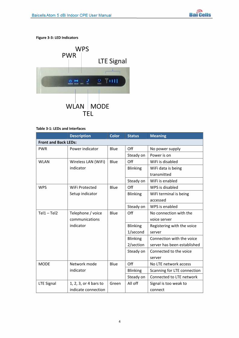
Figure 3-3: LED Indicators
Table 3-1: LEDs and Interfaces
Description Color Status Meaning Front and Back LEDs: PWR Power indicator Blue Off No power supply
Steady on Power is on WLAN Wireless LAN (WiFi)
indicator Blue Off WiFi is disabled
Blinking WiFi data is being transmitted
Steady on WiFi is enabled WPS WiFi Protected
Setup indicator Blue Off WPS is disabled
Blinking WiFi terminal is being accessed
Steady on WPS is enabled Tel1 – Tel2 Telephone / voice
communications indicator
Blue Off No connection with the voice server
Blinking 1/second
Registering with the voice server
Blinking 2/section
Connection with the voice server has been established
Steady on Connected to the voice server
MODE Network mode indicator
Blue Off No LTE network access Blinking Scanning for LTE connection Steady on Connected to LTE network
LTE Signal
1, 2, 3, or 4 bars to indicate connection
Green All off Signal is too weak to connect
5
status and signal strength. The more bars, the stronger the signal between the CPE and a cell site.
Steady on Bars will light steadily according to signal strength
(Back) LAN 1-4 Local Area Network Ethernet connection indicators
Green Off Ethernet connection is not established
Steady on Ethernet connection is normal
Blinking Ethernet interface data is being transmitted
Back Interfaces: Power Switch On/off power switch Power Port Power adaptor plug-in port Tel 1-2 Ports 2 RJ-11 ports for voice, fax, POS, or other VoIP functions under
conditions of software support LAN 1-4 Eth Ports
4 RJ-45 Local Area Network Ethernet ports
Two special status indications are explained in Table 3-2.
Table 3-2: Special Status Indicators
Status Indicator Description Firmware Upgrade The WLAN + WPS lights will flash simultaneously when the
CPE software is being upgraded Reset Process When the CPE is being reset (rebooted), all indicator lights
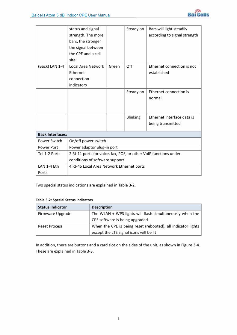
except the LTE signal icons will be lit In addition, there are buttons and a card slot on the sides of the unit, as shown in Figure 3-4. These are explained in Table 3-3.
6
Figure 3-4: Sides of CPE Unit
Table 3-3: Side Buttons and Card Slot
Name Description Restore Button Press down the Restore button for at least 10 seconds to restore
the CPE to its factory settings WPS WiFi Protected Setup (security) WiFi Turn on/off the WiFi function USIM Slot 1.8V/3.0V Universal Subscriber Identity Module (USIM)
7
4. Installation Follow the steps below to install the Atom 5 dBi indoor CPE.
Attention: Make sure the CPE is turned off before you insert or remove the SIM card. Otherwise, the CPE and SIM card may be damaged.
1. Insert the SIM card into the USIM slot on the side of the unit. Note: To remove the SIM card, press down on the card and the card will pop up.
2. Insert the power adaptor, and turn the unit on. The power indicator should light up to indicate an operating power supply. If you have any problem with the unit or the power adaptor powering on the CPE, please contact your vendor.
3. Wait for 1 minute. If the MODE and LTE Signal Strength indicators flash simultaneously, it indicates that the SIM card did not connect to the device or is invalid. Please contact your vendor or service provider to validate the card or to provide a new SIM card.
4. If the MODE light flashes, it means the device is searching for or registering with the LTE network. If the device connects to the LTE network normally, the MODE indicator will remain on and the LTE Signal Strength indicators will reflect the LTE signal strength (1, 2, 3, or 4 bars). If the device cannot connect to the LTE network, the MODE indicator will begin blinking. If this is the case, please contact your vendor or service provider.
5. The WLAN indicator will show whether the wireless LAN (WLAN) / WiFi is enabled. If WiFi is enabled, mobile phones and laptops should be able to connect to the LTE network via WiFi. The WiFi Service Set Identifier (SSID) to look for and use is “Airtouch-8783”. No password is required the first time the device is used.
6. PCs and laptops can also be connected to the CPE using Ethernet cables to the LAN ports.
8
5. Basic Configuration To configure the Atom CPE, you will access the Web-based CPE GUI application. Follow the steps provided to log in and complete the minimal configuration requirements for the CPE to operate. For more detailed configuration information, refer to the Baicells Configuration and Network Administration Guide on the Baicells support website.
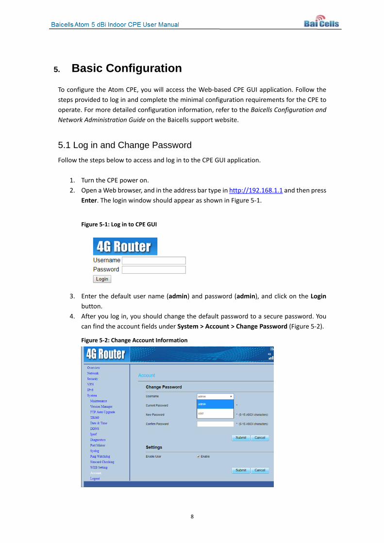
5.1 Log in and Change Password Follow the steps below to access and log in to the CPE GUI application.
1. Turn the CPE power on. 2. Open a Web browser, and in the address bar type in http://192.168.1.1 and then press
Enter. The login window should appear as shown in Figure 5-1.
Figure 5-1: Log in to CPE GUI
3. Enter the default user name (admin) and password (admin), and click on the Login
button. 4. After you log in, you should change the default password to a secure password. You
can find the account fields under System > Account > Change Password (Figure 5-2).
Figure 5-2: Change Account Information
9
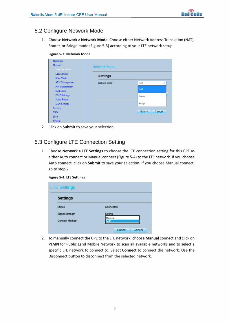
5.2 Configure Network Mode 1. Choose Network > Network Mode. Choose either Network Address Translation (NAT),
Router, or Bridge mode (Figure 5-3) according to your LTE network setup.
Figure 5-3: Network Mode
2. Click on Submit to save your selection.
5.3 Configure LTE Connection Setting 1. Choose Network > LTE Settings to choose the LTE connection setting for this CPE as
either Auto connect or Manual connect (Figure 5-4) to the LTE network. If you choose Auto connect, click on Submit to save your selection. If you choose Manual connect, go to step 2.
Figure 5-4: LTE Settings
2. To manually connect the CPE to the LTE network, choose Manual connect and click on
PLMN for Public Land Mobile Network to scan all available networks and to select a specific LTE network to connect to. Select Connect to connect the network. Use the Disconnect button to disconnect from the selected network.
10
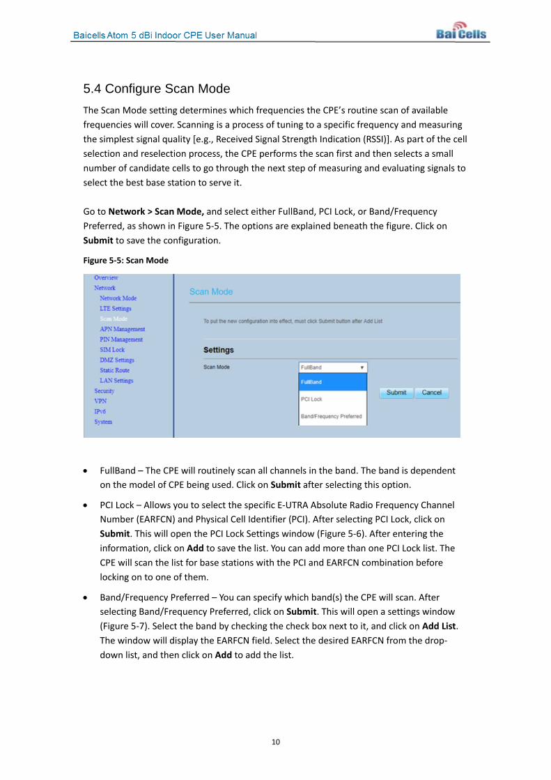
5.4 Configure Scan Mode The Scan Mode setting determines which frequencies the CPE’s routine scan of available frequencies will cover. Scanning is a process of tuning to a specific frequency and measuring the simplest signal quality [e.g., Received Signal Strength Indication (RSSI)]. As part of the cell selection and reselection process, the CPE performs the scan first and then selects a small number of candidate cells to go through the next step of measuring and evaluating signals to select the best base station to serve it. Go to Network > Scan Mode, and select either FullBand, PCI Lock, or Band/Frequency Preferred, as shown in Figure 5-5. The options are explained beneath the figure. Click on Submit to save the configuration.
Figure 5-5: Scan Mode
• FullBand – The CPE will routinely scan all channels in the band. The band is dependent on the model of CPE being used. Click on Submit after selecting this option.
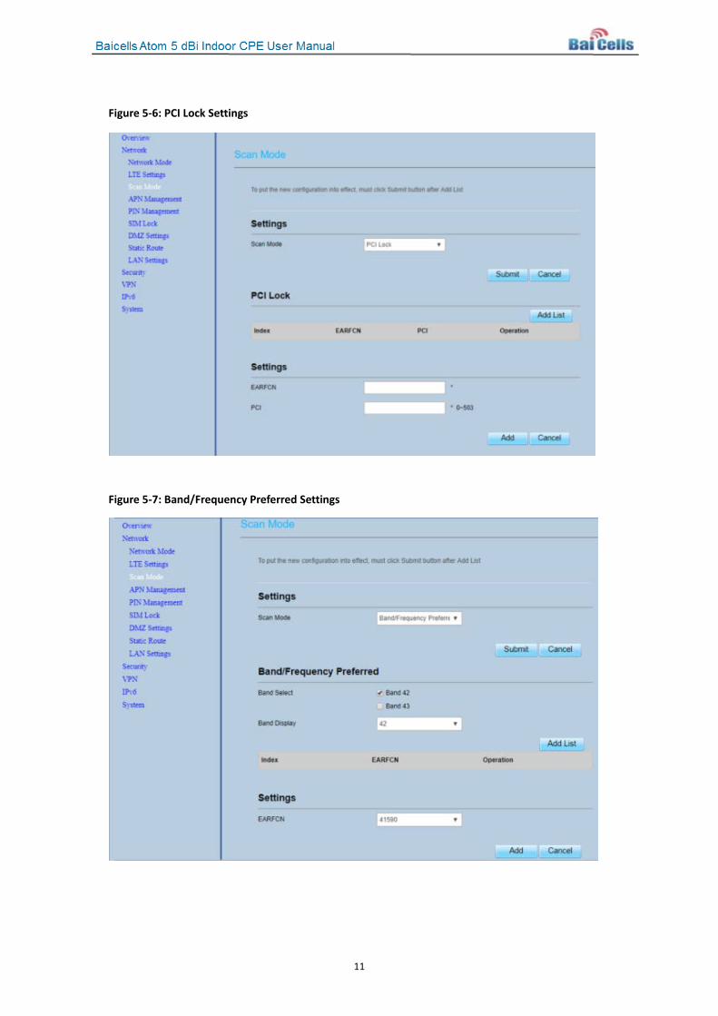
• PCI Lock – Allows you to select the specific E-UTRA Absolute Radio Frequency Channel Number (EARFCN) and Physical Cell Identifier (PCI). After selecting PCI Lock, click on Submit. This will open the PCI Lock Settings window (Figure 5-6). After entering the information, click on Add to save the list. You can add more than one PCI Lock list. The CPE will scan the list for base stations with the PCI and EARFCN combination before locking on to one of them.
• Band/Frequency Preferred – You can specify which band(s) the CPE will scan. After selecting Band/Frequency Preferred, click on Submit. This will open a settings window (Figure 5-7). Select the band by checking the check box next to it, and click on Add List. The window will display the EARFCN field. Select the desired EARFCN from the drop-down list, and then click on Add to add the list.
11
Figure 5-6: PCI Lock Settings
Figure 5-7: Band/Frequency Preferred Settings
12
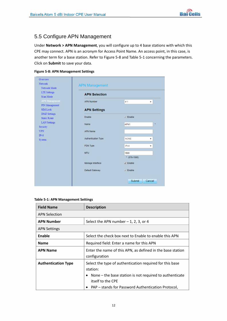
5.5 Configure APN Management Under Network > APN Management, you will configure up to 4 base stations with which this CPE may connect. APN is an acronym for Access Point Name. An access point, in this case, is another term for a base station. Refer to Figure 5-8 and Table 5-1 concerning the parameters. Click on Submit to save your data.
Figure 5-8: APN Management Settings
Table 5-1: APN Management Settings
Field Name Description
APN Selection
APN Number Select the APN number – 1, 2, 3, or 4
APN Settings
Enable Select the check box next to Enable to enable this APN
Name Required field: Enter a name for this APN
APN Name Enter the name of this APN, as defined in the base station configuration
Authentication Type Select the type of authentication required for this base station: • None – the base station is not required to authenticate
itself to the CPE • PAP – stands for Password Authentication Protocol,
13
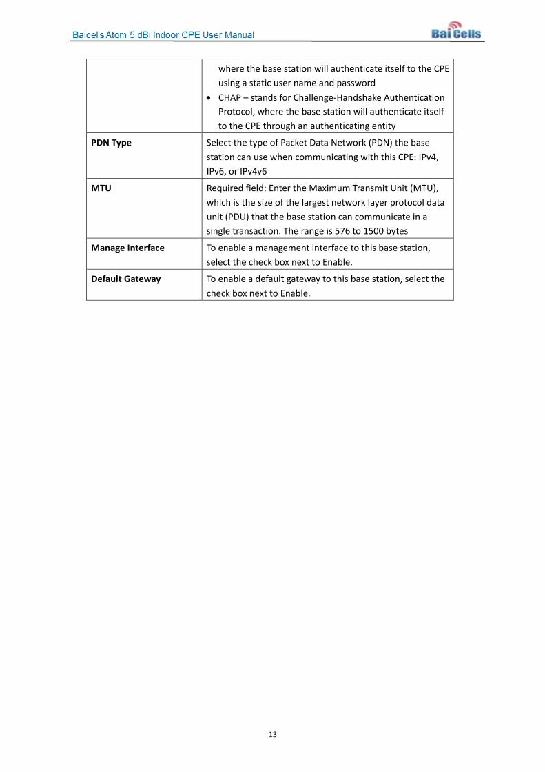
where the base station will authenticate itself to the CPE using a static user name and password
• CHAP – stands for Challenge-Handshake Authentication Protocol, where the base station will authenticate itself to the CPE through an authenticating entity
PDN Type Select the type of Packet Data Network (PDN) the base station can use when communicating with this CPE: IPv4, IPv6, or IPv4v6
MTU Required field: Enter the Maximum Transmit Unit (MTU), which is the size of the largest network layer protocol data unit (PDU) that the base station can communicate in a single transaction. The range is 576 to 1500 bytes
Manage Interface To enable a management interface to this base station, select the check box next to Enable.
Default Gateway To enable a default gateway to this base station, select the check box next to Enable.
14
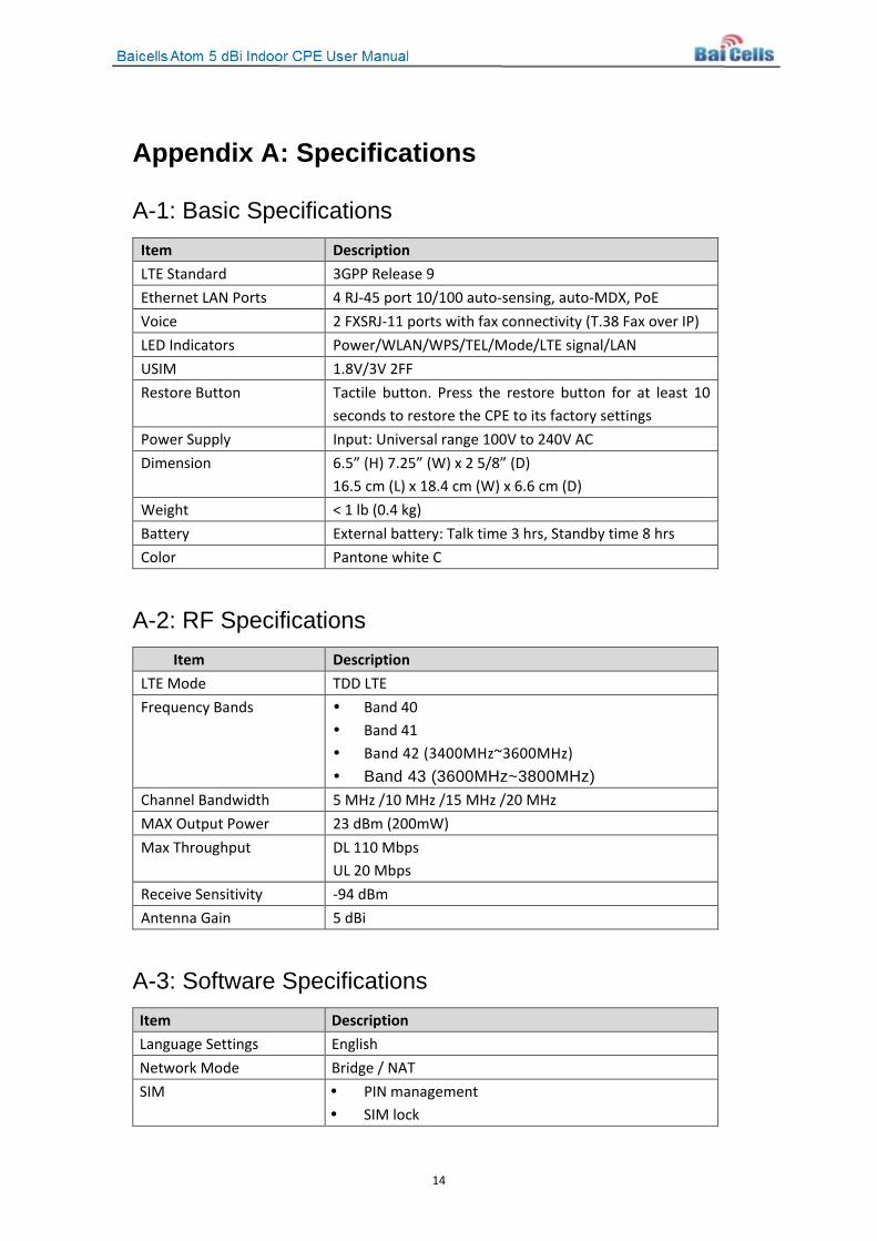
Appendix A: Specifications
A-1: Basic Specifications Item Description LTE Standard 3GPP Release 9 Ethernet LAN Ports 4 RJ-45 port 10/100 auto-sensing, auto-MDX, PoE Voice 2 FXSRJ-11 ports with fax connectivity (T.38 Fax over IP) LED Indicators Power/WLAN/WPS/TEL/Mode/LTE signal/LAN USIM 1.8V/3V 2FF Restore Button Tactile button. Press the restore button for at least 10
seconds to restore the CPE to its factory settings Power Supply Input: Universal range 100V to 240V AC Dimension 6.5” (H) 7.25” (W) x 2 5/8” (D)
16.5 cm (L) x 18.4 cm (W) x 6.6 cm (D) Weight < 1 lb (0.4 kg) Battery External battery: Talk time 3 hrs, Standby time 8 hrs Color Pantone white C
A-2: RF Specifications Item Description
LTE Mode TDD LTE Frequency Bands Band 40
Band 41 Band 42 (3400MHz~3600MHz) Band 43 (3600MHz~3800MHz)
Channel Bandwidth 5 MHz /10 MHz /15 MHz /20 MHz MAX Output Power 23 dBm (200mW) Max Throughput DL 110 Mbps
UL 20 Mbps Receive Sensitivity -94 dBm Antenna Gain 5 dBi
A-3: Software Specifications Item Description Language Settings English Network Mode Bridge / NAT SIM PIN management
SIM lock
15
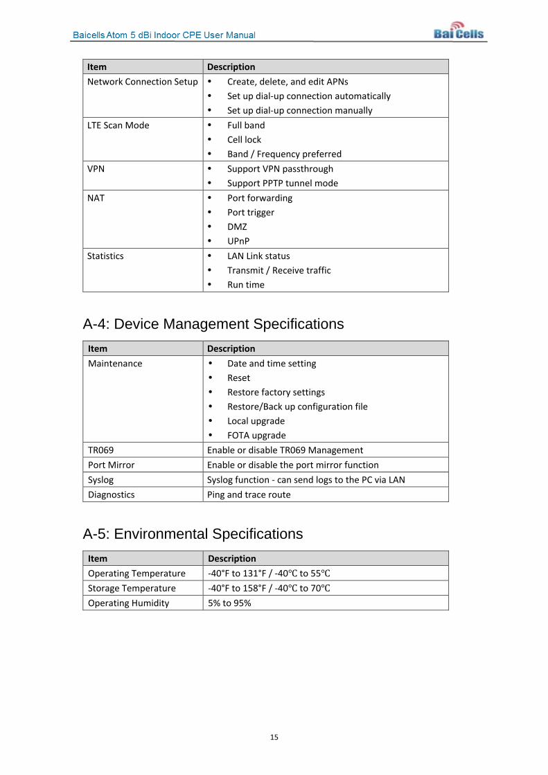
Item Description Network Connection Setup Create, delete, and edit APNs
Set up dial-up connection automatically Set up dial-up connection manually
LTE Scan Mode Full band Cell lock Band / Frequency preferred
VPN Support VPN passthrough Support PPTP tunnel mode
NAT Port forwarding Port trigger DMZ UPnP
Statistics LAN Link status Transmit / Receive traffic Run time
A-4: Device Management Specifications Item Description Maintenance Date and time setting
Reset Restore factory settings Restore/Back up configuration file Local upgrade FOTA upgrade
TR069 Enable or disable TR069 Management Port Mirror Enable or disable the port mirror function Syslog Syslog function - can send logs to the PC via LAN Diagnostics Ping and trace route
A-5: Environmental Specifications Item Description Operating Temperature -40°F to 131°F / -40℃ to 55℃ Storage Temperature -40°F to 158°F / -40℃ to 70℃ Operating Humidity 5% to 95%

16
Appendix B: FAQs If you have questions, please check the list of frequently asked questions (FAQs) on the Baicells support website or the Facebook support forum.
• Baicells support website - https://na.Baicells.com/support/
• Baicells support forum on Facebook - https://www.facebook.com/groups/Baicellsoperatorsupportgroup/