Embed Size (px)
Citation preview
1
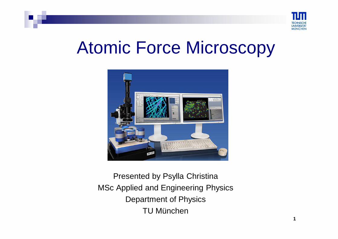
Atomic Force Microscopy
Presented by Psylla ChristinaMSc Applied and Engineering Physics
Department of PhysicsTU München
2
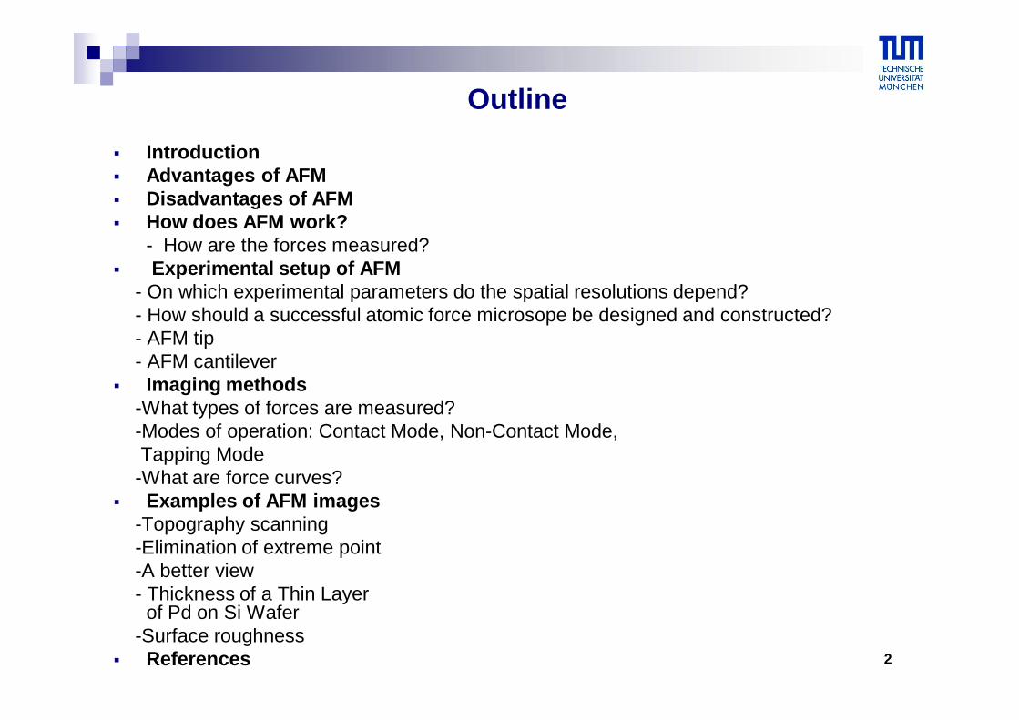
Outline Introduction Advantages of AFM Disadvantages of AFM How does AFM work?
- How are the forces measured? Experimental setup of AFM
- On which experimental parameters do the spatial resolutions depend?- How should a successful atomic force microsope be designed and constructed?- AFM tip- AFM cantilever
Imaging methods-What types of forces are measured?-Modes of operation: Contact Mode, Non-Contact Mode,Tapping Mode
-What are force curves? Examples of AFM images
-Topography scanning-Elimination of extreme point-A better view- Thickness of a Thin Layer
of Pd on Si Wafer-Surface roughness
References
3
Introduction
Atomic force microscopy is a high resolution type of scanning probe microscopy that allows us to see and measure surface structure in length scale 10nm-100μm with unprecedented resolution and accuracy(lateral resolution~30 nm, vertical resolution~0.1 nm)
Unlike an imaging traditional microscope, AFM provides height information of the sample
Almost any sample can be imaged, be it very hard (ceramic material) or very soft (human cells, individual molecules of DNA)
We can generate images which look at the sample from any conceivable angle with simple analysis software
Currently AFM is the most common form of scanning probe microscopy and is used in all fields of science as chemistry, biology, physics, materials science, nanotechnology, astronomy, medicine and more
4
Advantages of AFM
minimal sample preparation
it does not require a conductive sample
provides a three-dimensional surface profile (ability to magnify in the X,Y,Z axes)
works perfectly well in ambient air or even a liquid environment
possible to study biological macromolecules and even living organisms
it does not require expensive equipment
due to its small size, it can also be combined with other microscopes or intruments
5
Disadvantages of AFM
not practical to make measurements on areas greater than 100μm
limited scanning speed, requiring several minutes for a typical scan
images can be affected by nonlinearity, hysterisis and creep of the piezoelectric material
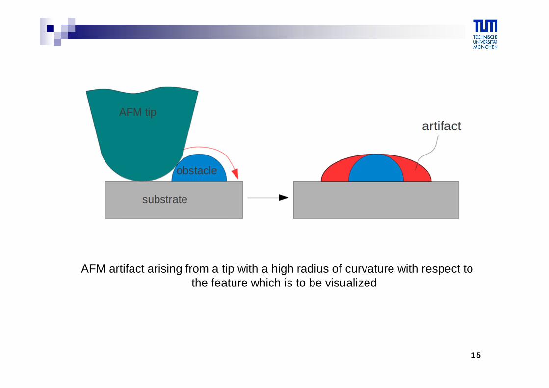
possibility of image artifacts
an AFM image does not reflect the true sample topography, but rather represents the interaction of the probe with the sample surface
6
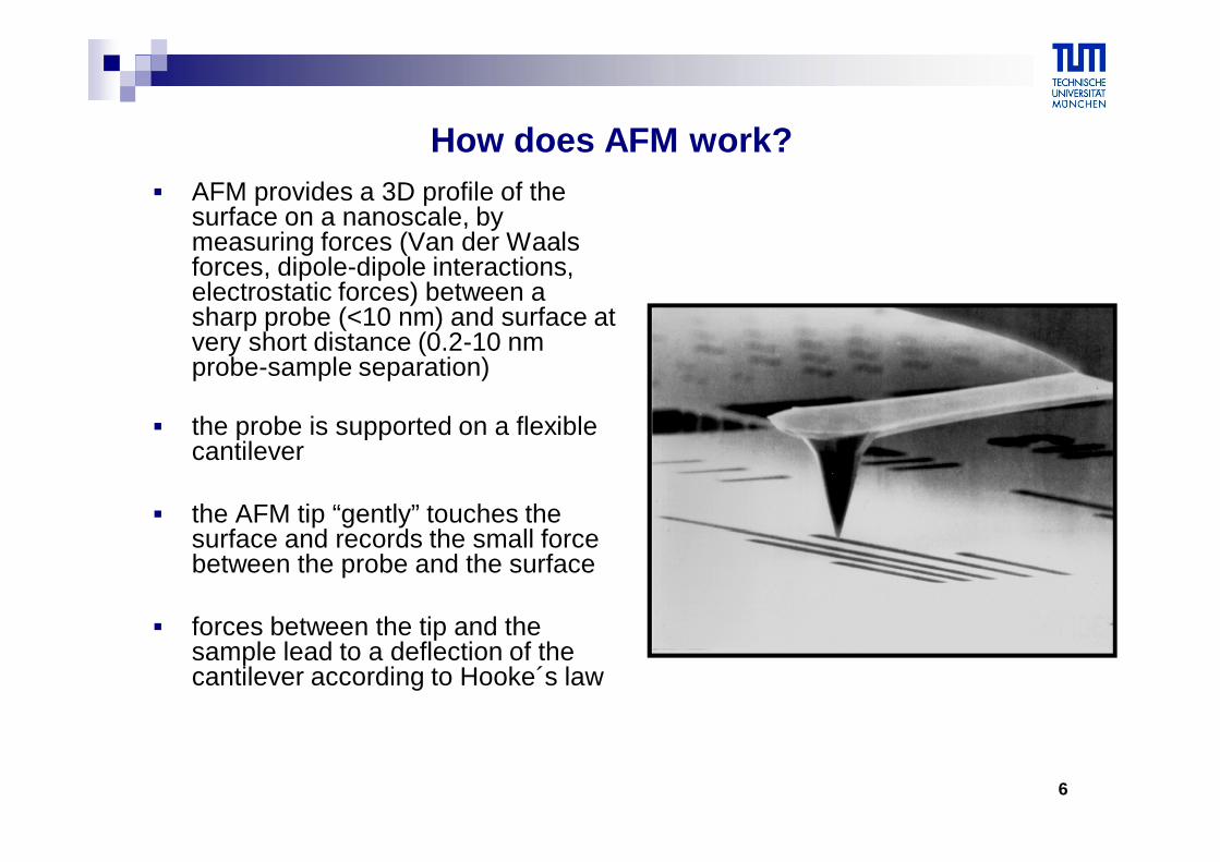
How does AFM work? AFM provides a 3D profile of the
surface on a nanoscale, by measuring forces (Van der Waals forces, dipole-dipole interactions, electrostatic forces) between a sharp probe (<10 nm) and surface at very short distance (0.2-10 nm probe-sample separation)
the probe is supported on a flexible cantilever
the AFM tip “gently” touches the surface and records the small force between the probe and the surface
forces between the tip and the sample lead to a deflection of the cantilever according to Hooke´s law
7
How are the forces measured?
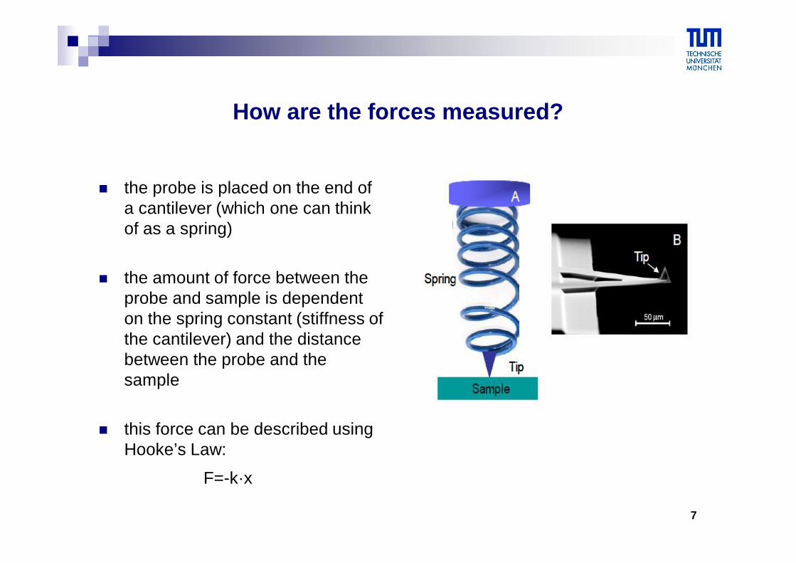
the probe is placed on the end of a cantilever (which one can think of as a spring)
the amount of force between the probe and sample is dependent on the spring constant (stiffness of the cantilever) and the distance between the probe and the sample
this force can be described using Hooke’s Law:
F=-k·x
8
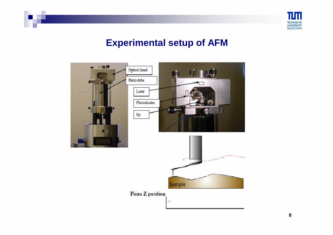
Experimental setup of AFM
9
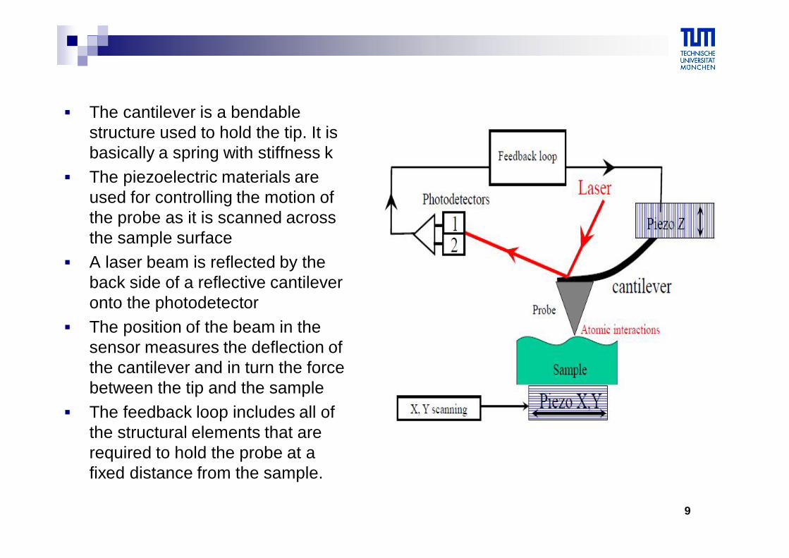
The cantilever is a bendable structure used to hold the tip. It is basically a spring with stiffness k
The piezoelectric materials are used for controlling the motion of the probe as it is scanned across the sample surface
A laser beam is reflected by the back side of a reflective cantilever onto the photodetector
The position of the beam in the sensor measures the deflection of the cantilever and in turn the force between the tip and the sample
The feedback loop includes all of the structural elements that are required to hold the probe at a fixed distance from the sample.
10
On which experimental parameters do the spatial resolutions depend?
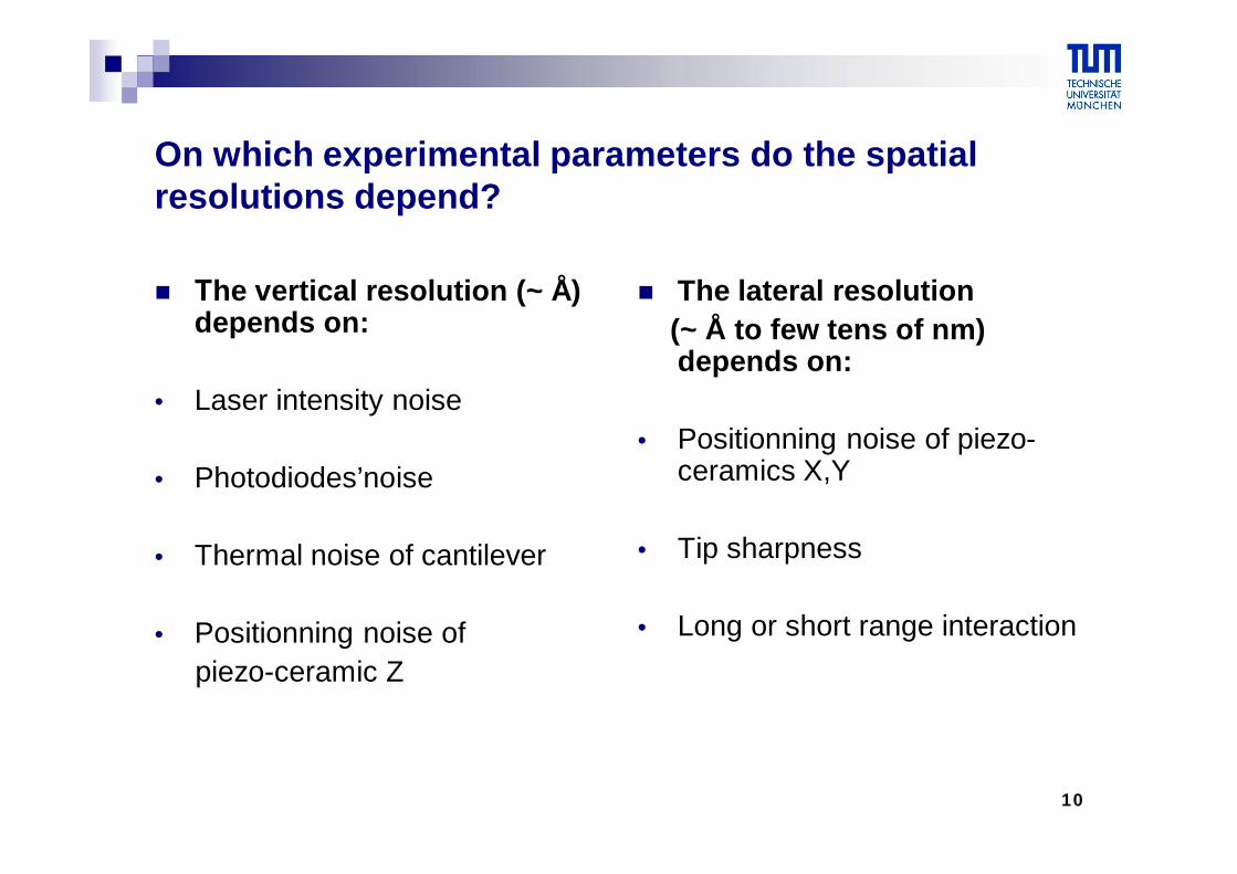
Τhe vertical resolution (~ Å) depends on:
• Laser intensity noise
• Photodiodes’noise
• Thermal noise of cantilever
• Positionning noise ofpiezo-ceramic Z
The lateral resolution (~ Å to few tens of nm) depends on:
• Positionning noise of piezo-ceramics X,Y
• Tip sharpness
• Long or short range interaction
11
How should a successful atomic force microsope be designed and constructed?
A very sharp probe must be constructed for measurement of high-resolution images
A feedback controller that permits rapid control so that the probe can follow the topography on the surface must be created
An X-Y-Z piezoelectric scanner that has linear and calibrated motion must be created
A stucture that is very rigid must be constructed, so that the probe does not vibrate relative to the surface
12
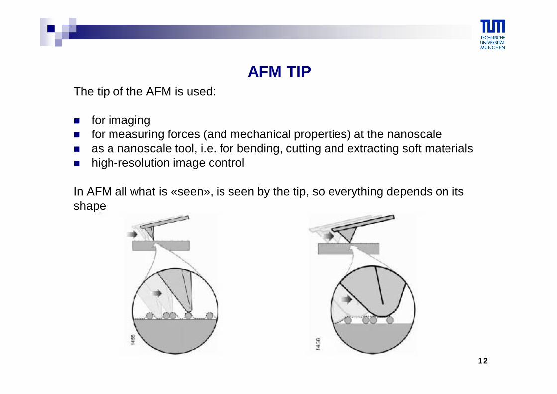
AFM TIPThe tip of the AFM is used:
for imaging for measuring forces (and mechanical properties) at the nanoscale as a nanoscale tool, i.e. for bending, cutting and extracting soft materials high-resolution image control
In AFM all what is «seen», is seen by the tip, so everything depends on itsshape
13
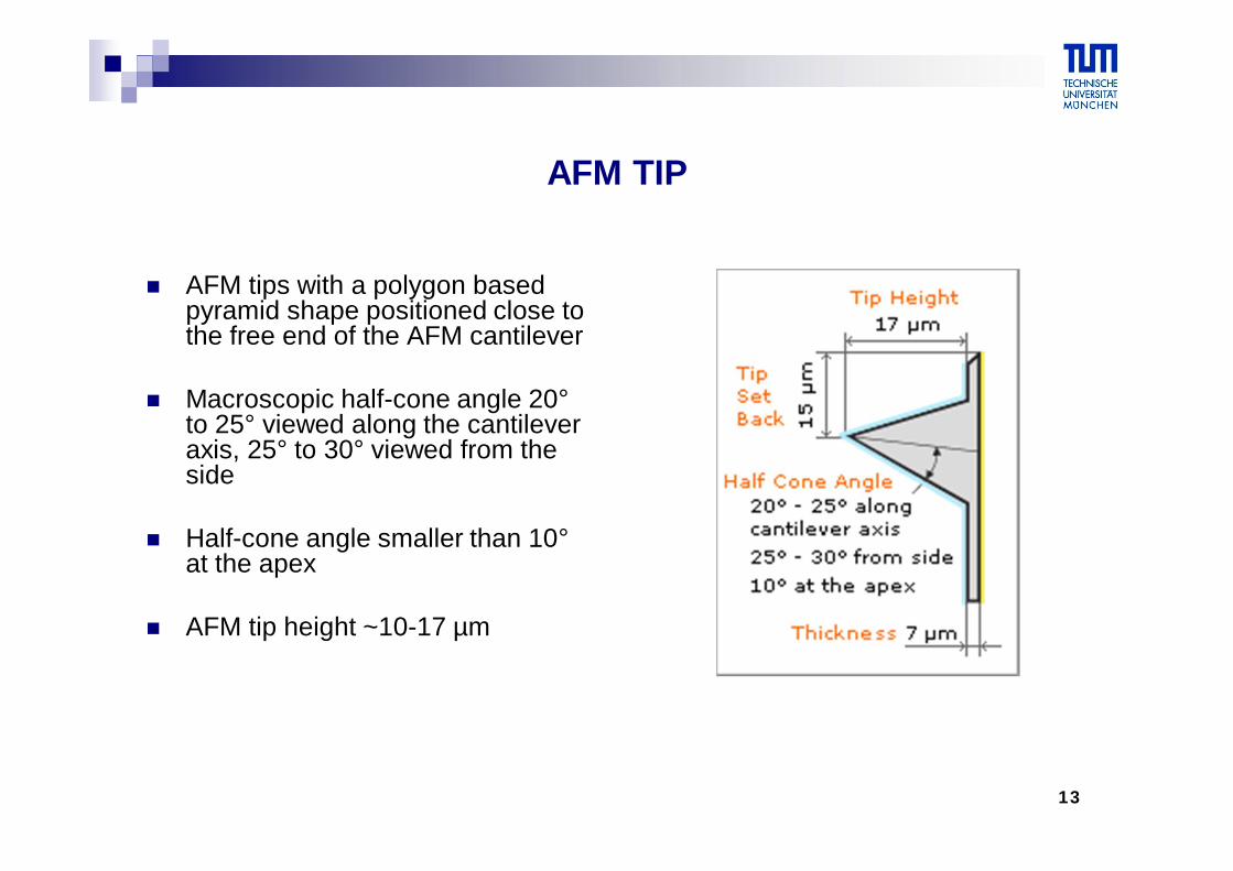
AFM TIP
AFM tips with a polygon based pyramid shape positioned close to the free end of the AFM cantilever
Macroscopic half-cone angle 20°to 25° viewed along the cantilever axis, 25° to 30° viewed from the side
Half-cone angle smaller than 10°at the apex
AFM tip height ~10-17 µm
14
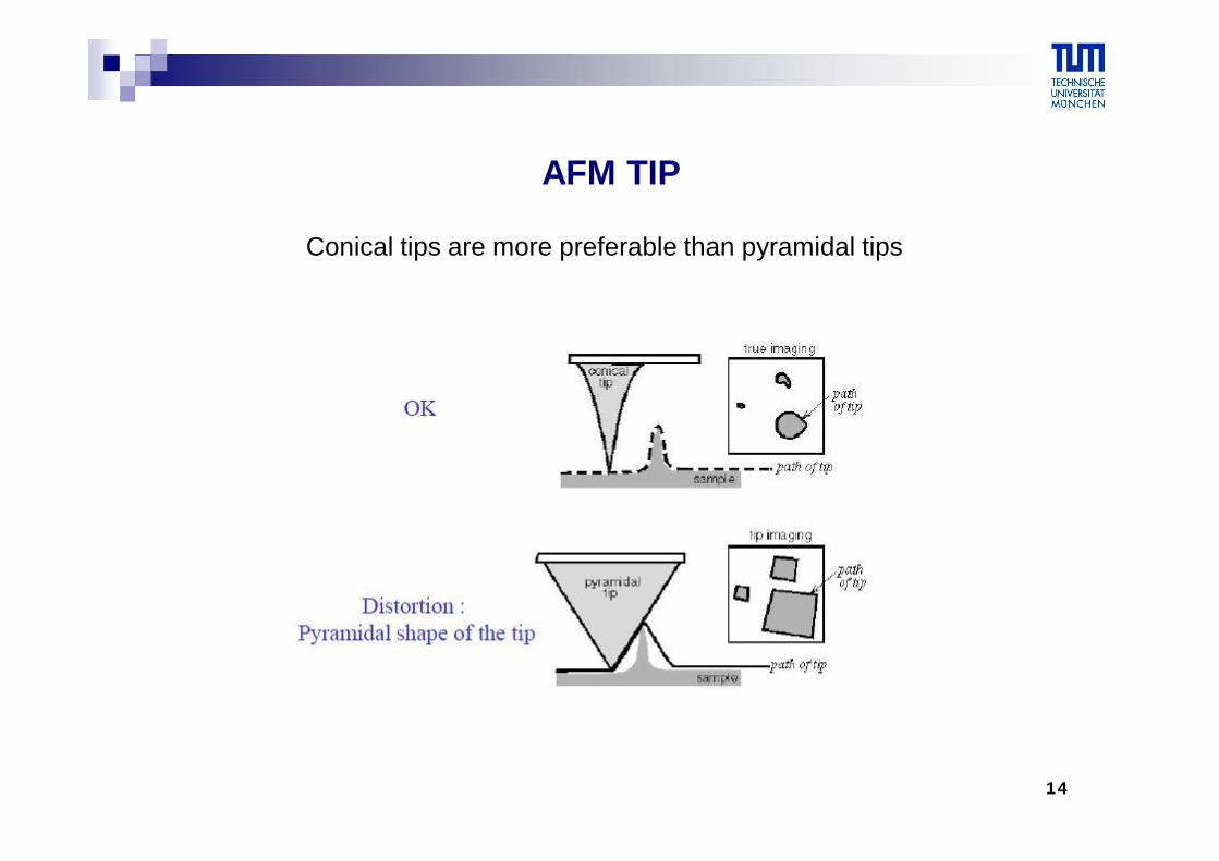
AFM TIP
Conical tips are more preferable than pyramidal tips
15
AFM artifact arising from a tip with a high radius of curvature with respect to the feature which is to be visualized
16
AFM CANTILEVER
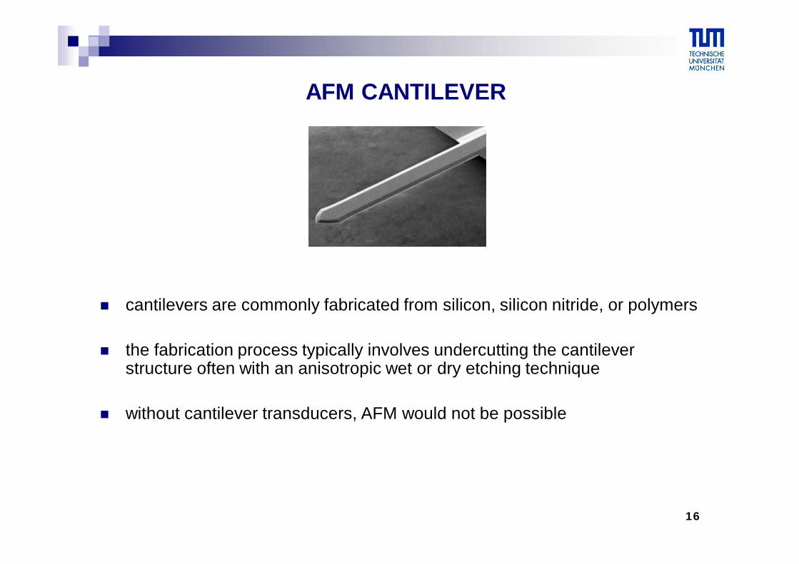
cantilevers are commonly fabricated from silicon, silicon nitride, or polymers
the fabrication process typically involves undercutting the cantilever structure often with an anisotropic wet or dry etching technique
without cantilever transducers, AFM would not be possible
17
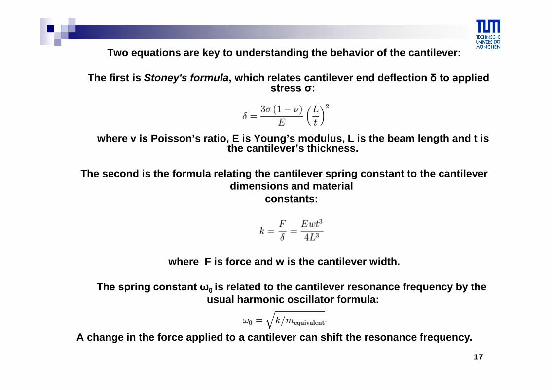
Two equations are key to understanding the behavior of the cantilever:
The first is Stoney's formula, which relates cantilever end deflection δ to applied stress σ:
where ν is Poisson’s ratio, E is Young’s modulus, L is the beam length and t is the cantilever’s thickness.
The second is the formula relating the cantilever spring constant to the cantileverdimensions and material
constants:
where F is force and w is the cantilever width.
The spring constant ω0 is related to the cantilever resonance frequency by theusual harmonic oscillator formula:
A change in the force applied to a cantilever can shift the resonance frequency.
18
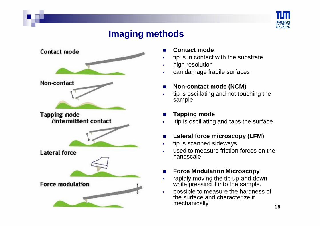
Imaging methods Contact mode• tip is in contact with the substrate• high resolution• can damage fragile surfaces
Non-contact mode (NCM) • tip is oscillating and not touching the
sample
Tapping mode• tip is oscillating and taps the surface
Lateral force microscopy (LFM)• tip is scanned sideways• used to measure friction forces on the
nanoscale
Force Modulation Microscopy• rapidly moving the tip up and down
while pressing it into the sample.• possible to measure the hardness of
the surface and characterize it mechanically
19
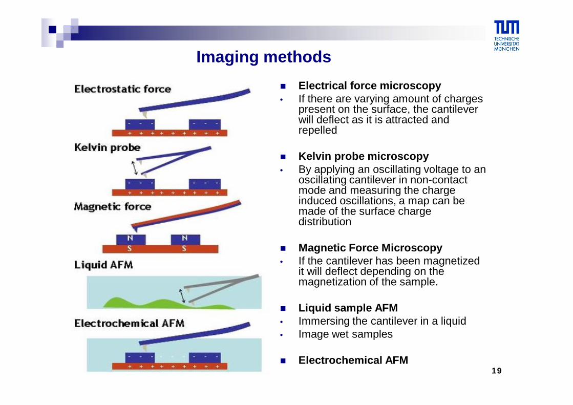
Imaging methods Electrical force microscopy• If there are varying amount of charges
present on the surface, the cantilever will deflect as it is attracted and repelled
Kelvin probe microscopy• By applying an oscillating voltage to an
oscillating cantilever in non-contact mode and measuring the charge induced oscillations, a map can be made of the surface charge distribution
Magnetic Force Microscopy• If the cantilever has been magnetized
it will deflect depending on the magnetization of the sample.
Liquid sample AFM• Immersing the cantilever in a liquid • Image wet samples
Electrochemical AFM
20
What types of forces are measured?
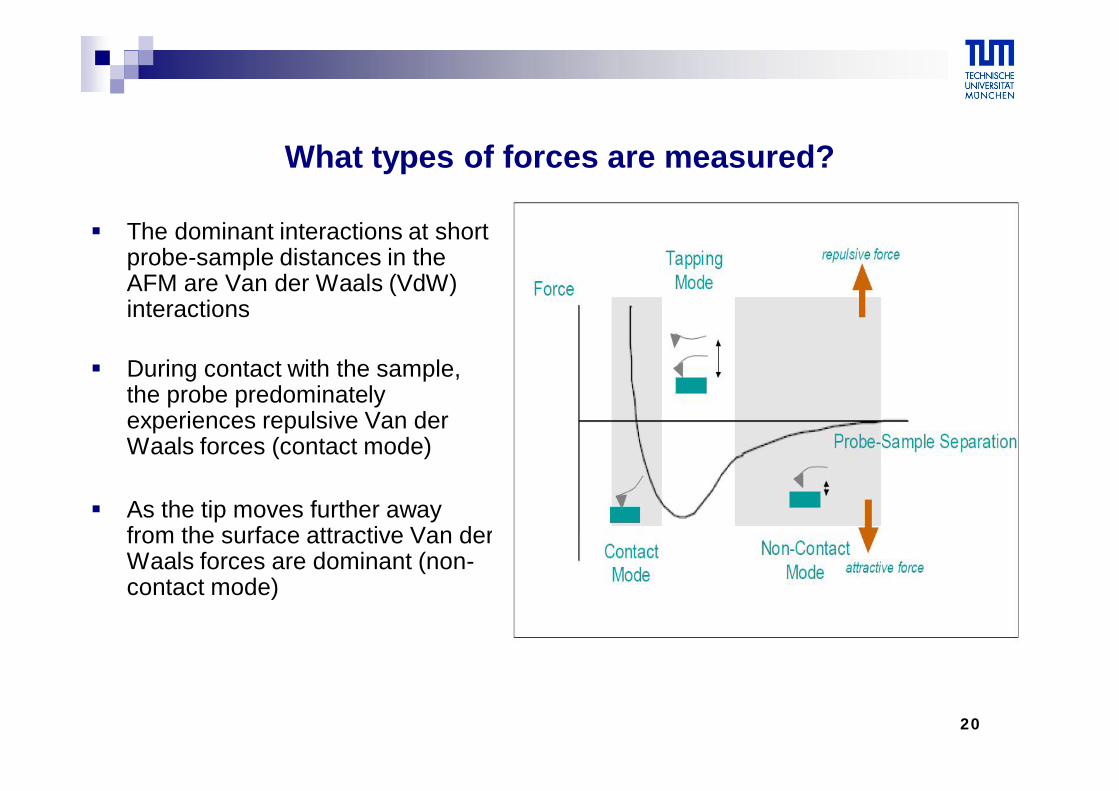
The dominant interactions at short probe-sample distances in the AFM are Van der Waals (VdW) interactions
During contact with the sample, the probe predominately experiences repulsive Van der Waals forces (contact mode)
As the tip moves further away from the surface attractive Van der Waals forces are dominant (non-contact mode)
21
Modes of operation
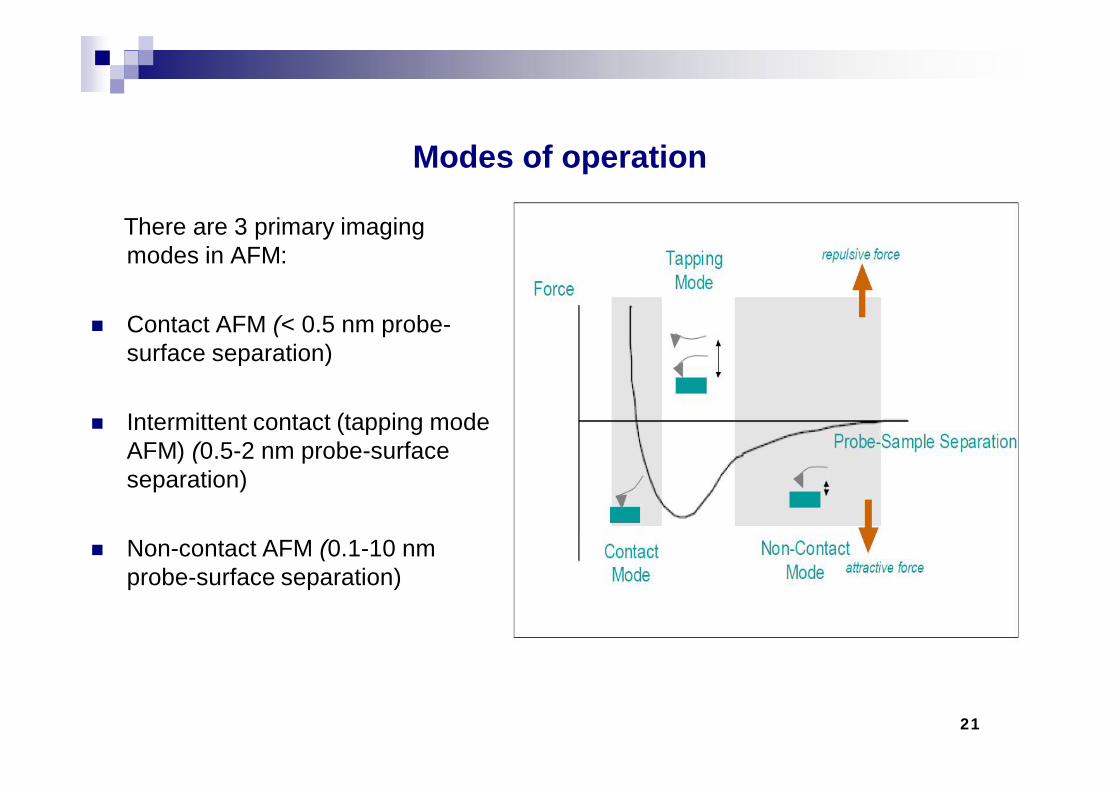
There are 3 primary imaging modes in AFM:
Contact AFM (< 0.5 nm probe-surface separation)
Intermittent contact (tapping mode AFM) (0.5-2 nm probe-surface separation)
Non-contact AFM (0.1-10 nm probe-surface separation)
22
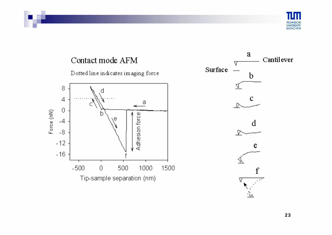
Contact mode (repulsive VdW)
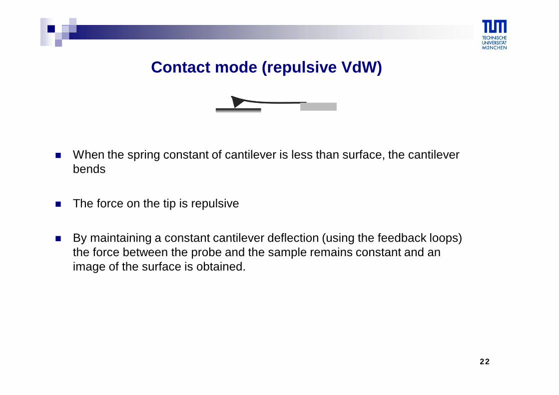
When the spring constant of cantilever is less than surface, the cantilever bends
The force on the tip is repulsive
By maintaining a constant cantilever deflection (using the feedback loops) the force between the probe and the sample remains constant and an image of the surface is obtained.
23
24
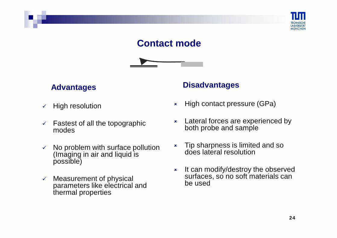
Contact mode
Advantages
High resolution
Fastest of all the topographic modes
No problem with surface pollution (Imaging in air and liquid is possible)
Measurement of physical parameters like electrical and thermal properties
Disadvantages
High contact pressure (GPa)
Lateral forces are experienced by both probe and sample
Tip sharpness is limited and so does lateral resolution
It can modify/destroy the observed surfaces, so no soft materials can be used
25
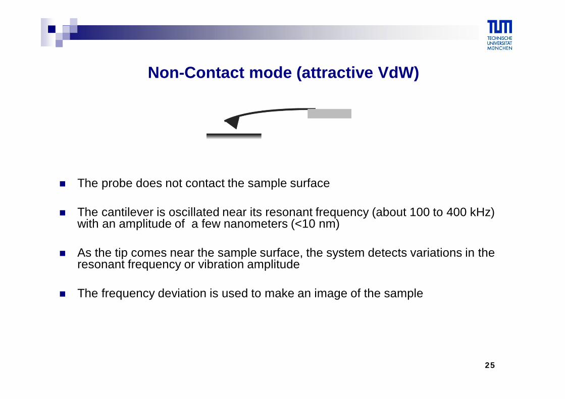
The probe does not contact the sample surface
The cantilever is oscillated near its resonant frequency (about 100 to 400 kHz) with an amplitude of a few nanometers (<10 nm)
As the tip comes near the sample surface, the system detects variations in the resonant frequency or vibration amplitude
The frequency deviation is used to make an image of the sample
Non-Contact mode (attractive VdW)
26
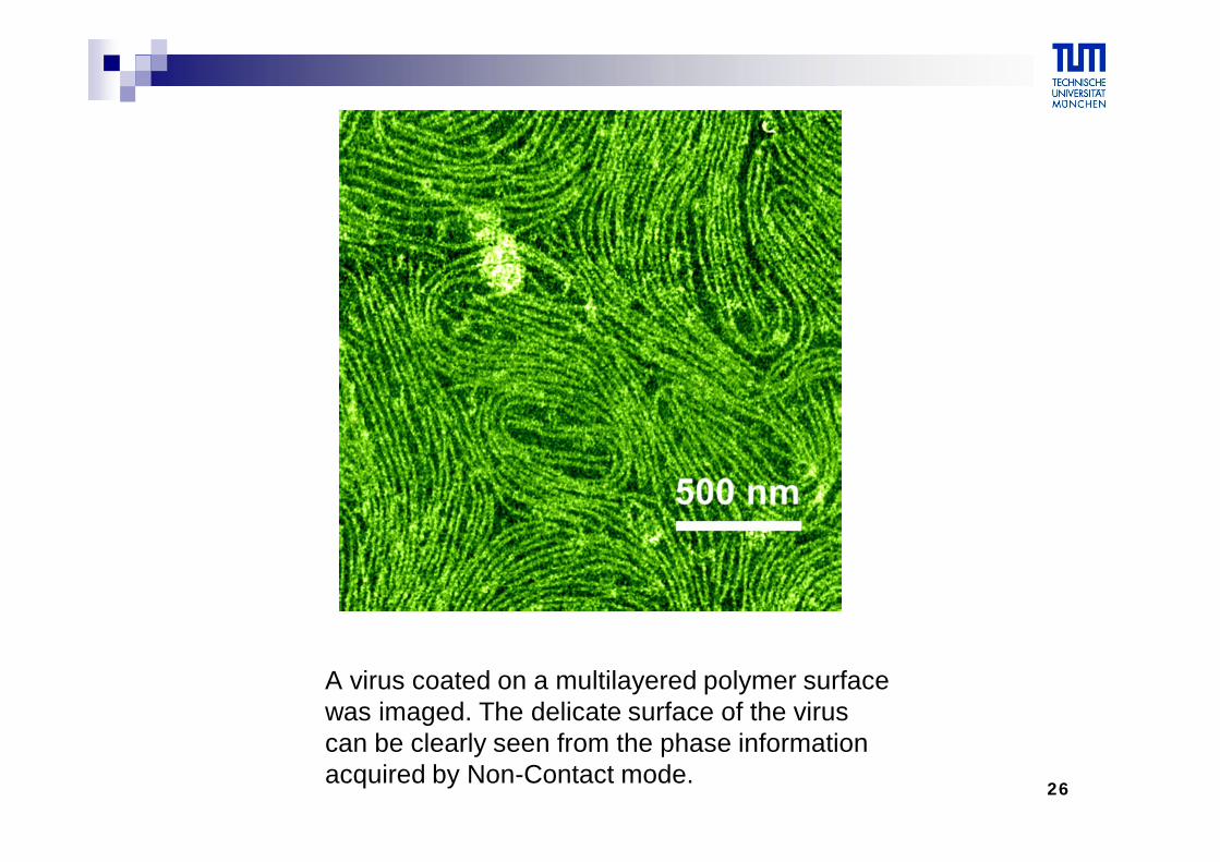
A virus coated on a multilayered polymer surface was imaged. The delicate surface of the viruscan be clearly seen from the phase informationacquired by Non-Contact mode.
27
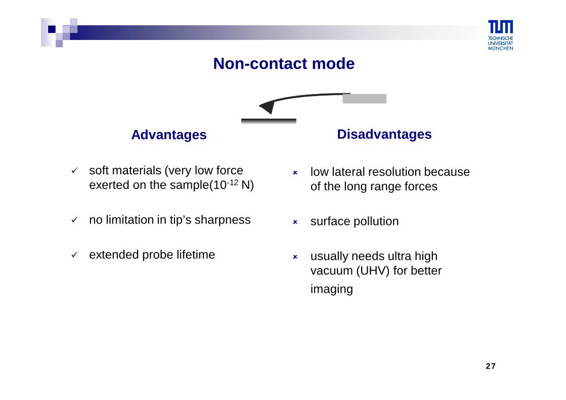
Non-contact mode
Advantages
soft materials (very low force exerted on the sample(10-12 N)
no limitation in tip’s sharpness
extended probe lifetime
Disadvantages
low lateral resolution because of the long range forces
surface pollution
usually needs ultra high vacuum (UHV) for better imaging
28
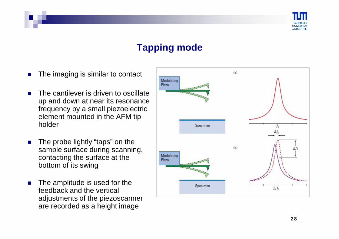
Tapping mode
The imaging is similar to contact
The cantilever is driven to oscillate up and down at near its resonance frequency by a small piezoelectric element mounted in the AFM tip holder
The probe lightly “taps” on the sample surface during scanning, contacting the surface at the bottom of its swing
The amplitude is used for the feedback and the vertical adjustments of the piezoscanner are recorded as a height image
29
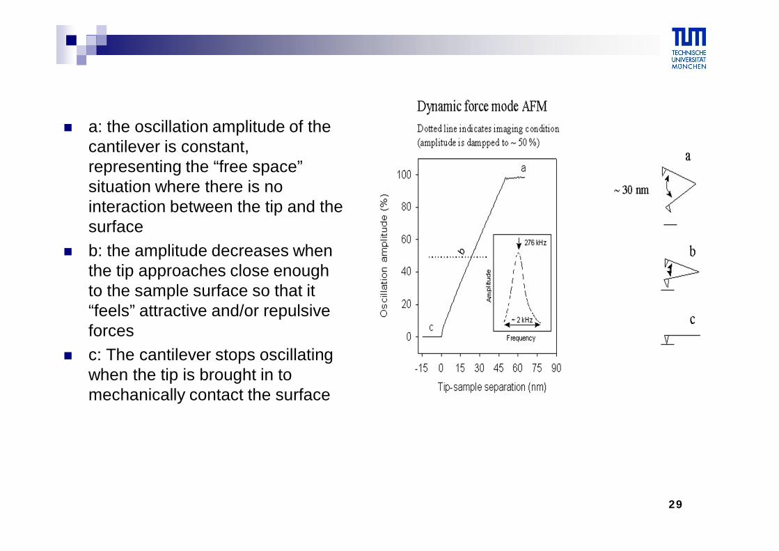
a: the oscillation amplitude of the cantilever is constant, representing the “free space” situation where there is no interaction between the tip and the surface
b: the amplitude decreases when the tip approaches close enough to the sample surface so that it “feels” attractive and/or repulsive forces
c: The cantilever stops oscillating when the tip is brought in to mechanically contact the surface
30
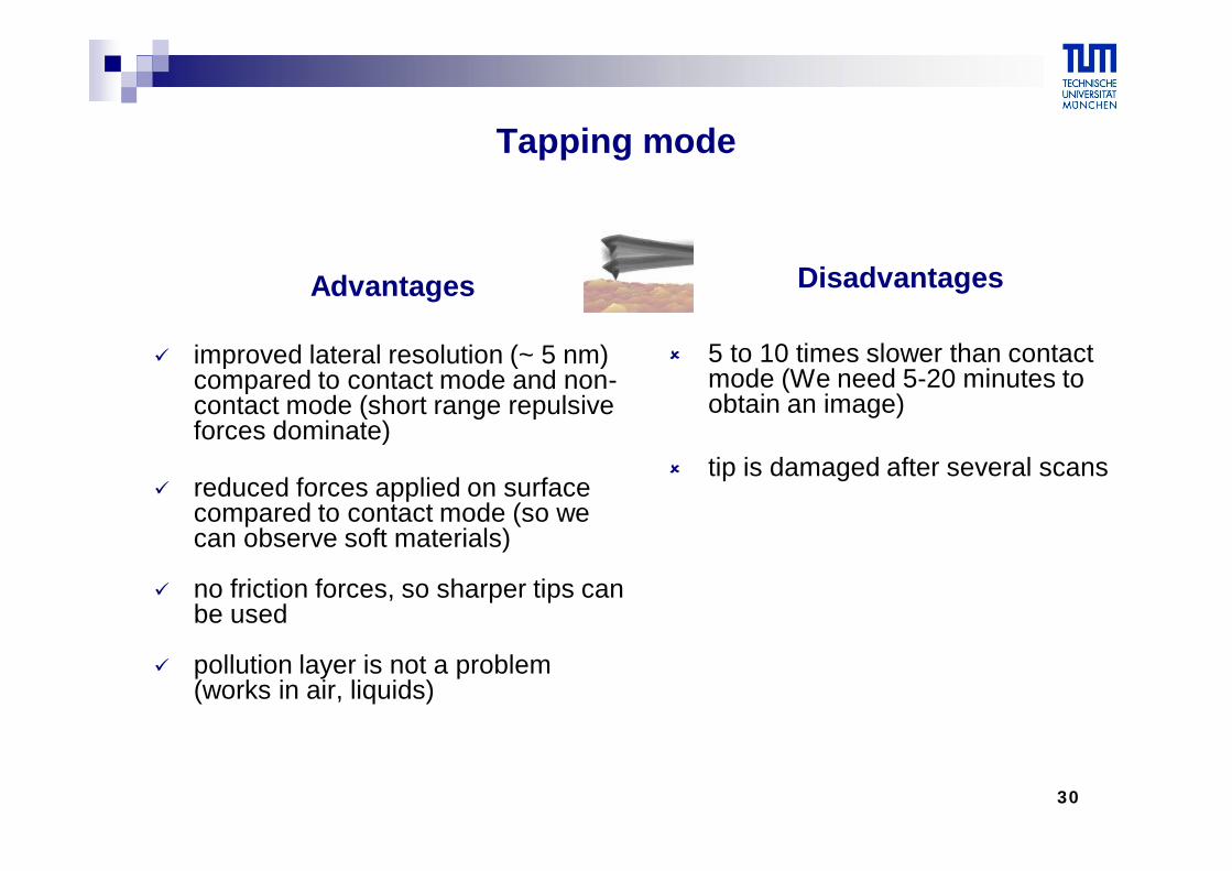
Tapping mode
Advantages
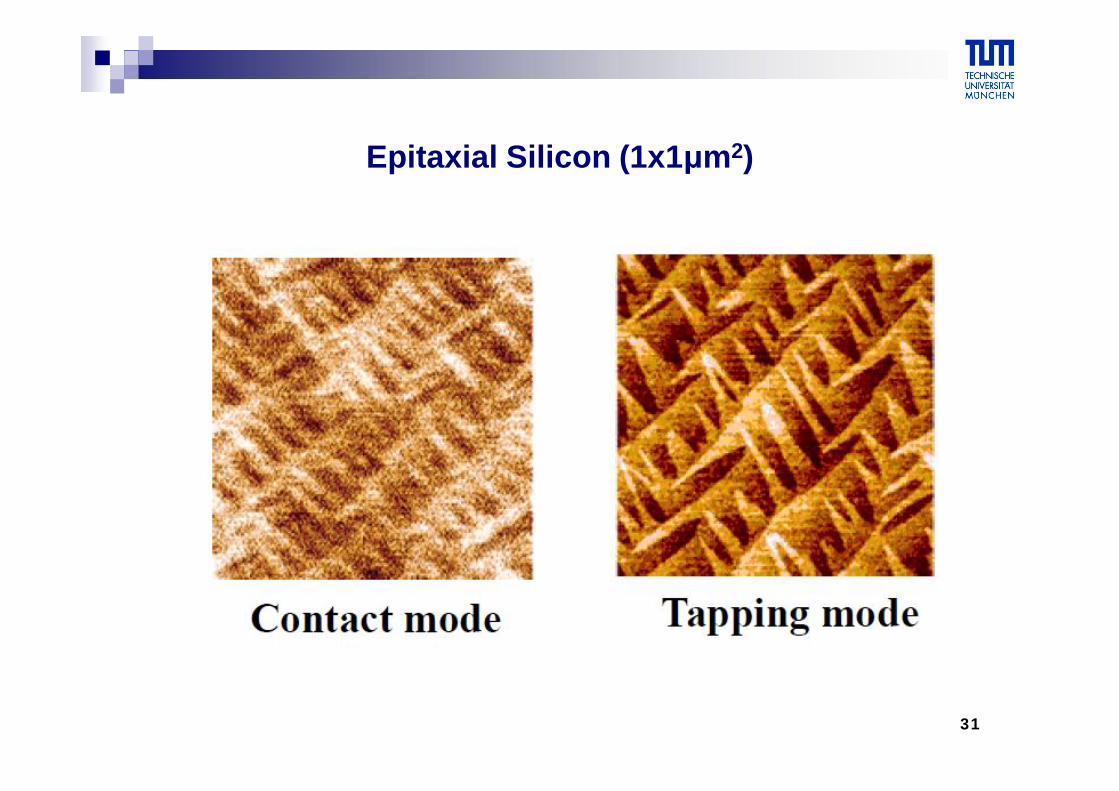
improved lateral resolution (~ 5 nm) compared to contact mode and non-contact mode (short range repulsive forces dominate)
reduced forces applied on surface compared to contact mode (so we can observe soft materials)
no friction forces, so sharper tips can be used
pollution layer is not a problem (works in air, liquids)
Disadvantages
5 to 10 times slower than contact mode (We need 5-20 minutes to obtain an image)
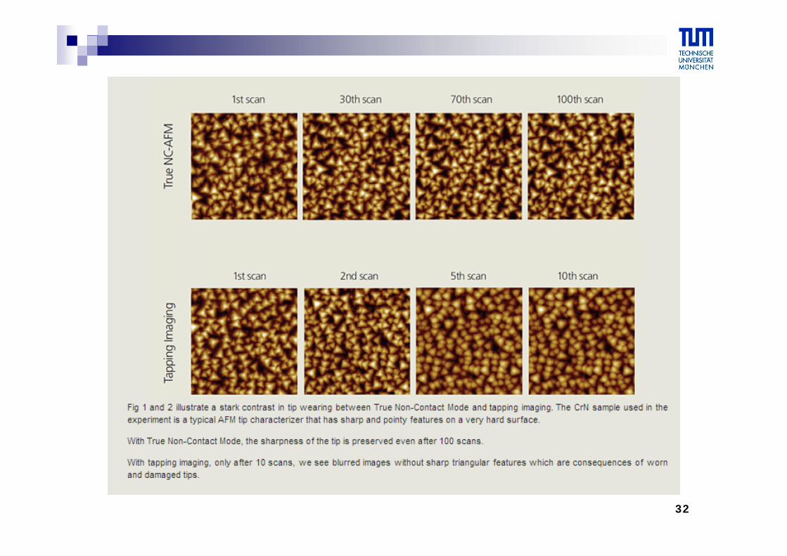
tip is damaged after several scans
31
Epitaxial Silicon (1x1μm2)
32
33
What are force curves?
Force curve analyses can be used to determine chemical and mechanical properties such as adhesion, elasticity, hardness and rupture bond lengths
Force curves measure the amount of force felt by the cantilever as the probe tip is brought close to - and even indented into - a sample surfaceand then pulled away
In a force curve analysis the probe is repeatedly brought towards the surface and then retracted
34
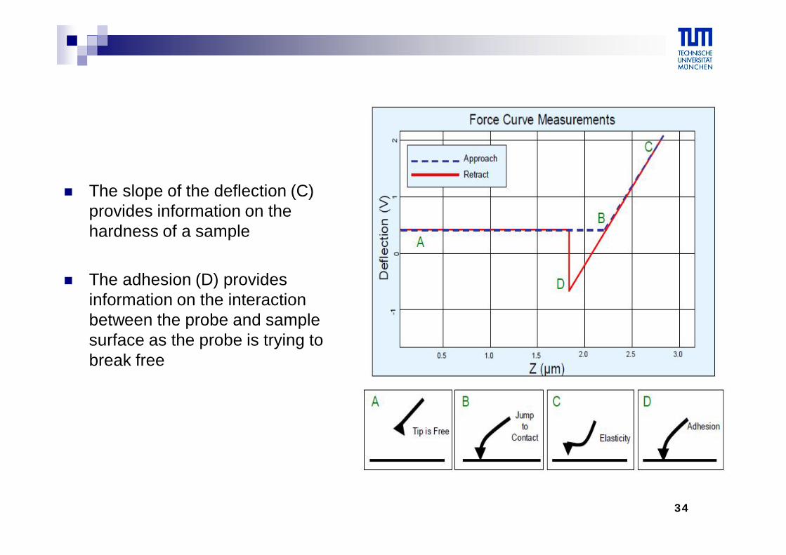
The slope of the deflection (C) provides information on the hardness of a sample
The adhesion (D) provides information on the interaction between the probe and sample surface as the probe is trying tobreak free
35
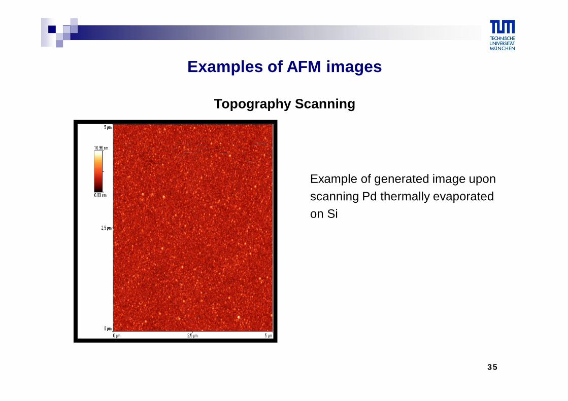
Example of generated image uponscanning Pd thermally evaporatedon Si
Examples of AFM images
Topography Scanning

36
Elimination of Extreme Points
This targets the highest points of the sample and eliminates them
It then manipulates the image to create a smaller dynamic depth
37
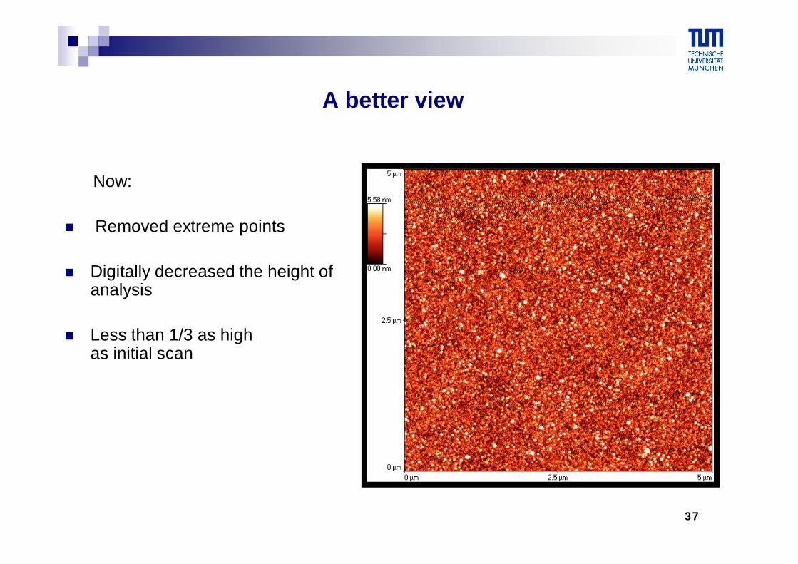
A better view
Now:
Removed extreme points
Digitally decreased the height of analysis
Less than 1/3 as high as initial scan
38
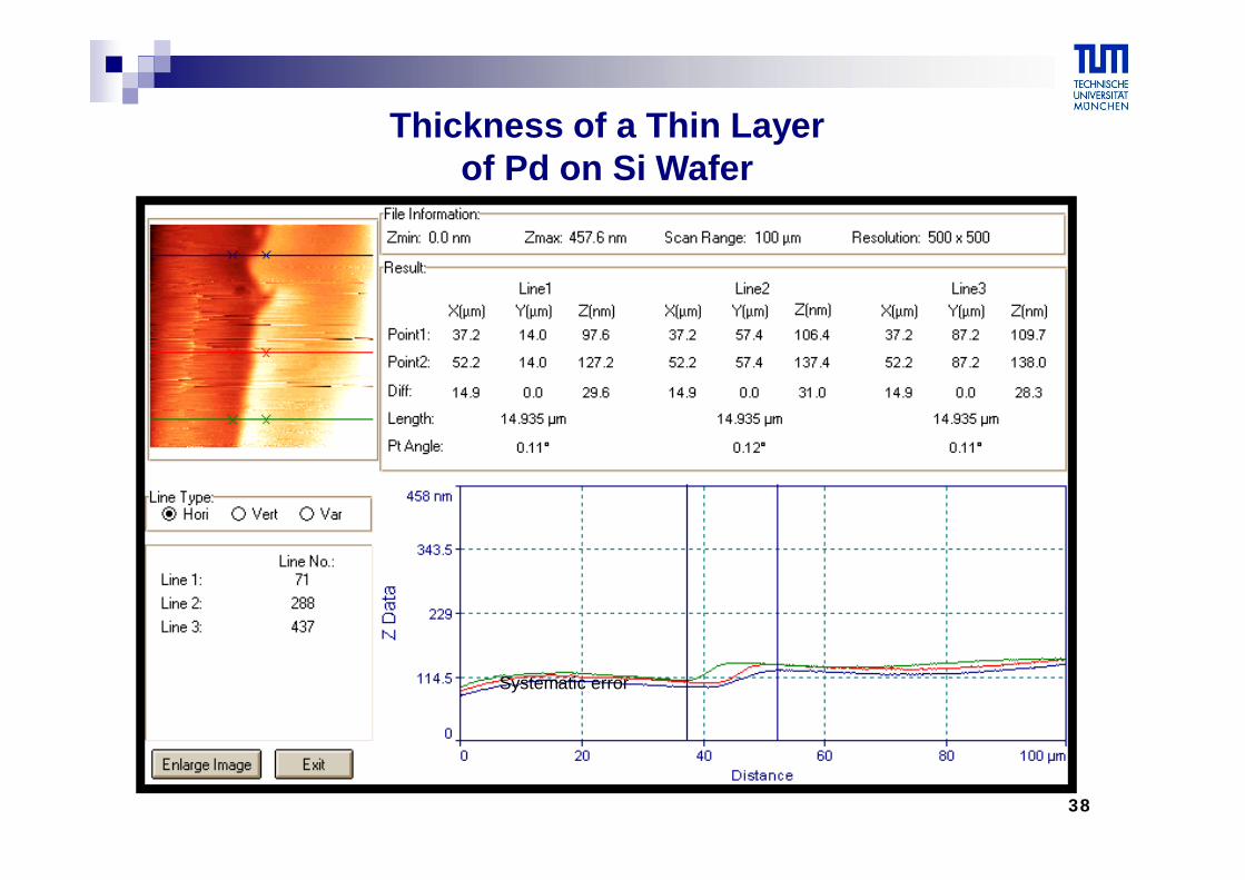
Thickness of a Thin Layerof Pd on Si Wafer
Systematic error
39
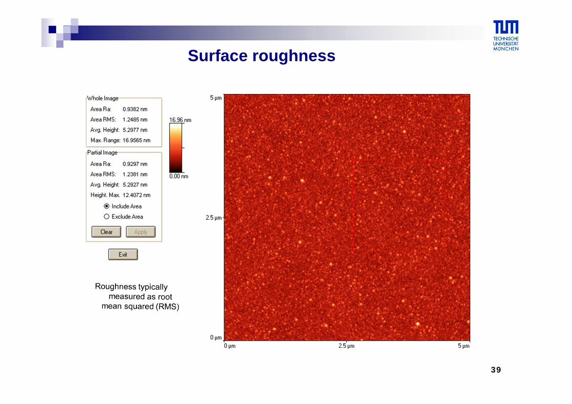
Surface roughness
40
References
“Atomic Force Microscopy” by Peter Eaton and Paul West
“Atomic Force Microscopy & CT-AFM” by K.Bouzehouane
Automatic drift elimination in probe microscope images based on techniques of counter-scanning and topography feature recognition”Yurov, A. N. Klimov (1994)
“Scanning tunneling microscope calibratiion and reconstruction of real image: Drift and slope elimination” G. Schitter, M. J. Rost (2008)
Introduction to Scanning Probe Microscopy (SPM) Basic Theory Atomic Force Microscopy (AFM) Robert A. Wilson and Heather A. Bullen,* Department of Chemistry, Northern Kentucky University, Highland Heights, KY 41099.