Embed Size (px)
Citation preview
IIII~I..1~_..~\~.L!IIIII--------------------------""--------_II
" ,
TIIII!!I!!!!!
18 AUGUST 1960
BY
ERIC B. KULAand
NORBERT H. FAHEY
IIIIIIIQIIIJ
WATERTOWN ARSENALLABORATORIES
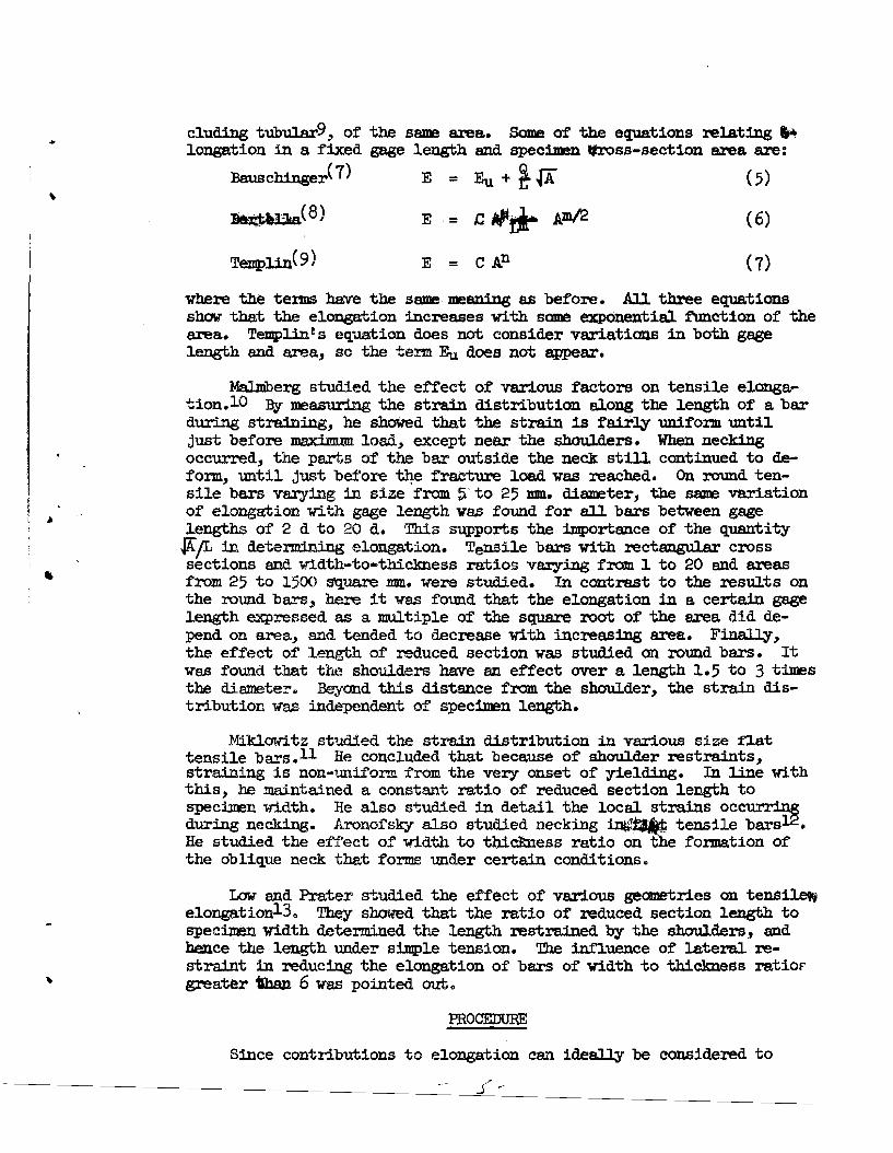
S I 2FRACTURE APPEARANCE OF GRIDDED
SHEET TENSILE SPECIMEN
.Atonograp/" $e,.ie~
INUMBER II IEFFECT OF SPECIMEN GEOMETRY ON DETERMINATION)OF ELONGATION IN SHEET TENSILE SPECIMENS
#~~ ..,,<\"~~-,l~'· ",j
o \
~\', 11,,'. ~I
~
CC>~
C~
C)Ci-'j
p .•~'
-.,1: .;,' !

\
..1
THE EFFECT OF SPECIMEN GEOMETRY ON DETERMINATIONOF ELONGATION IN SHEET TENSILE SPECIMENS
BY
ERIC B. KULAand
NORBERT H. FAHEY
PRESENTED AT SEVENTH SAGAMOREORDNANOE MATERIALS RESEARCH
CONFERENCE
18 AUGUST 1960
'"
TEE EFFECT OF SPECIMEN GEOMETRY ON DETERMINATIONOF ELONGATION IN SHEET TENSILE SPEClMENS
by
Eric B. KulaHarbert H. Fahey
1'iatertown Arsenal Laboratories
/tA., 'f' '~ INTRODUCTION
The current~terest in sheet material. has emphasized th~dfor a more accurat~understanding of the s=,t:icance of ductili'Ey ofmaterials. This is especially true of elo :elon, which is the mostcommon means of assessing the ductility of sheet materiaJ.s:J Dnfortunately,weongation val.ues depend on such geometrical. factors as
~specimen hl.ckness and width in addition to gage length and the inher-ent ductility of the material itse~ As a convenience, a constantgage length and §l:Peci:men1\width are used as the A. S. T.M. standard sheettensile specimen1, but this means that ~heelongationof specimens ofdifferent thicknesses are not strictly CODg>a.r~;:=-I If an interrelationship be'tween elonga.tion, gage length, spec n Width, and specimenthickness could be determined, either anaJ.ytic~ or empiricaJ.ly, itwould be possible to correlat~ctilitYrf9r materiaJ.s of widely different size and shape. rTe..4 ..riOIrr i,..rJ1-J
Recognizing that elongation vaJ.ues can be a:ffected by end restraint, type of fracture, etc. J but convinced that elongation is moredependent on specimen size,~e pr:i.ma.r,y purpose of this paper is toobtain a greater understand.iiig of elongation as a I1Easure of the ductility of plate and sheet materials as affected by specimen size andgage length.J These other variables were studied, together with theinfluence of specimen geometry on yield and tensile strength, and willbe reported at a later date.
LITERATlJRE RE~'1
There has been considerable interest in the effects of specimengeOlnetry on tensile properties end cnpeciaJ.ly elongation in the past.The older European litcr'abJ:r'(: ~<~3~been reviewed ,in Handbuch derWerkstoffprUfung2 ) :,rhereas much of the American literature is reviewedin a recent DMIC report3•
\' Quantitative relations between elongation and gage length and/orcross-section geometry generally take two forms:
a. variation of elongation with gage length for specimens ofa given cross-section, and
b. variation of elongation 'With specimen area in speciIllenswith differing cross-section size an~or geometry but with the samegage lengt~
~~uations relating elongation and gage length have been 1mpor'tmrt oeccn.1se of the great number of gage lengths in common use and the I..~ -~J ,»
- 1-
,
•
(2)
( 4)
( 6)
r c ~1+~""3)1 +~ -j ,
E - Eu • (Eo - Eu)a-(I/Do)2n
EaEu=Q{AL
E .. C = A!J1/2r.m
Berte11e.(8)
Krisch and Kuntze(6)
wl;1ereE = per cent elongation
Eu = per cent elongation measured on an infinite1¥ longgage length
Eo i: peZ" cent elongation :measu:red on a zero gage lengthRA = per cent reduction in area
L = gage lengthDo = ori.g:i..ns.JJ. diameter
A = original a.'r'IeaB,C,Q,a,m,n, = constants
rr;" all the equatiotlS it is reco~ized that the elcmga.tion decrt:mses to some limiting value as the gage 1.ength approaches infiJUtxJThis is generaJ.1¥ ternled the inf'inite gage length elonga"tion. (In somecases the l.:imiting elongation :for zero gage length is used. This canbe caJ.culated f·I'Ql1l. the red,uction in area 'i:.r constancy of wl:ume isassumed. Between these lilniting iT'8J.:ues'the elcmge;t;ion dec:re88es withincreasing gage length, in a cOlI!l;plex 1Jxponential manner a.cco:rding toKrisch 6lld -Kmr!;ze, or 'With an exponential f\mction of the reciprocal.of the gage length. This e..xponent is 1 a.c(~oi'ding to Martens, Gallik,and Bauschinger)1 2 acco!"d.i.ng to Ba.ch, and arbi"trary according toBerte~A:1
~/~
The dependence of elo:agation on specimen cross-section area hasaJ.~ been recognizedo This can be seen by the designation of gagelength as some multiple of spec:1Jren diameter. Even for :recten.gularspecimens, gage lengths have been specified as a multiple of the squa:reroat of the a.reao Since the elci.ngation depends on the area and nat thedimensions, "the cross..section sha;pe is nat iJDportant. Te:lqpUn:reported similar elongation vaJ.ues for various sbap$d specimens, in-
(deS1rabUity of comparing elongation vaJ.ues. Throughout the world, thegage lengths used for determin:lng elongation va:r:r from 3.54 to 10 timesthe spec1JDen diameter for round spec1mens2 (4 to 11.3 times the areafor flat spec1D:ens).1J Even inside one country, two or more gage lengths~ be used. rsome, of the equations :relating elongation Bnd gage length iJe (e ,I
are. ' E: rel}/('~,cc"i
o Martens( 4) E .. Eu := i (1) ------'
BE ... C =,
iloE-Eu='L
cluding tubula.r9, of' the same area. Some of the equations relating ,.longation in a fixed gage length and specimen !Itross-section area are:
Ba:uschinger( 7) E = Eu + ~.fA (5)
1Ie)$~(8) E = t;"~ Am/2 (6)
E = C A.n
, .
vhere the terms have the same· meaning as before. All three equationsshow that the elongation increases with SCDDl! exponential. :f\m.ction of thearea. Templin t S equation does not consider variations in both gagelength and area, so the te:rm Eu does not ~ar.
MalJDberg studied the effect of various factors on tensile elongation.10 By measuring the strain distribution along the length of a barduring straining, he showed that the strain is fair~ uniform untiljust before maximum. load, except near the shoul.ders. When neckingoccurred, the parts of the bar outside the neck still continued to deform, until just before t~e fracture l.oad vas reached. On round tensile bars varying in size from 5' to 25 mm. diameter, the same variationof elongation vith gage length vas found for all bars between gagel.engths of 2 d to 20 d. This supports the importance of the quantity
IAfL in determining elongation. Tensile bars 'With recta.ne;ular crosssections and width-to-thickness ratios varying from 1 to 20 and areasfrom 25 to 1500 square mm. were studied. In contrast to the results onthe round bars, here it was fotmd that the elongation in a certain gagel.ength expressed as a multiple of the square root of the area did depend on area, and tended to decrease with increasing area. FjnaJly,the effect of length of reduced section was studied on round bars. Itwas found that the shoulders have an effect over a length 1.5 to 3 timesthe diameter. Beyond this distance from the shoulder, the strain distribution was independent of specimen length.
Miklowitz studied the strain distribution in various size t'J.attensile bars. ll He concluded that because of shou:Lder restraints,straining is non-uniform t"'rom. the very onset of yielding. In line withthis, be maintained a constant ratio of reduced section length tospecimen width. He also studied in detail the local strains occurringduring necking. Aronofsky also studied necking iI$1~ tensile bars12•He studied the ef'f'ect of width to thickness ratio on the formation ofthe oblique neck tha.t forms under certain conditions.
Low and Prater studied the ef'fect of various geometries on tensi~
elongation13. Th.ey showed that the ratio of reduced section length tospecimen 'Width determined the length restrained by the shoul.d.ers, andhence· the length under simpl.e tension. The i.n:f'l.uence of lateral restraint in reducing the elongation of bars of 'Width to thickness ratiofgreater'iban 6 was pointed out.
PROCEIJURE
Since contributions to elongation can ideally be considered to
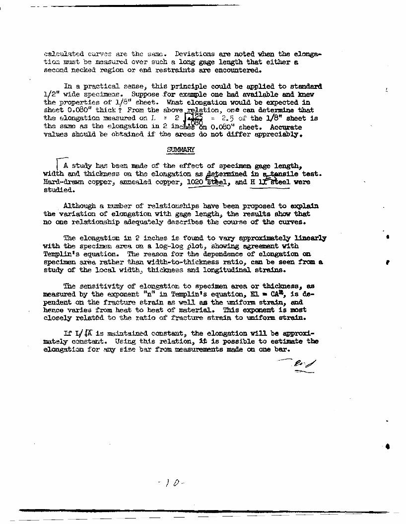
c!<:mIt f".ro!i two sources, the un1f'0:rm e1ongtltion and the extension associated nth the neck, the ef'fedt of' specimen ,geometry an these quanti..ties vas to be determined. This was a.ccOJll'lished by photogridd:1ng thespec1mms with a grid spacing of twenty to the inch sJ.ong the reducedsection and analyzing, the distr1bution of' strain th.ro1,Jgb.ou:t this regiQt\"with partiCUlar empha.siSp~ on the necked region. With this inmind the materials used, were sllected because of their dif'f'erences inlmif'o:rm strain values. The materiaJ.s used, each of which were individual. beats, were hard drawn Wld azmealed copper, AISI 1020 steel, andHlJ.. tool steel. The copper end aWl were obtained as 1/2" thick by! 1/1" Vide bar in :random lengths and, the H 11 vas SUWlied in 'J/ 8"sheet. Af'ter insuring the ~ity of' the material by macroetch1ngand ha:rdness su.rveys» tensile spec:1JDeDs of various thicknesses aDdw:l.dths were prepared f'rom the lf2" bar by slicing to the epp1'OX1JDatethickness and then careful. gr:i.n.ding to size. Specimem thicknesses from0.010 to 0.500 inches were prepared, nth widths rang:lng f'rom 1/8 to2 inches» see Figure 10 'lliis resul.ted in specimen width to thicknessratios of' f'rom 1:1 to 200:1 and areas ranging f'1'OJn 0.0013 to 1.00squa.re 1nch~!':::,
Tensile properties of' the various materiaJ..s used are summarizedin Table I.
..
,TABLE I
002%Yield Tensile Reduc- E1onga- ElongationJ
Strength Strength tion in tionp . Unifo:rm Spec:1.menMaterial psi psi Area, .'!o Total,10 10 Type
Copper, 34,800 37,000 6902 30.0 7·0 .357" Dharddrawneoc, , 8,900 313 000 79'4 3709\1+ 2605 0357" D
aJ.ed
1020 Steel 32,,300 : 55,900 63.0 37·1 25.0 0357" D'lIiilJ. ·!~~~~~fu."ooo 25°.ll900
!!lOa __ 808 500 1/2" X'lf8"TOOl Steel
The copper was :re~ived in the J::Ia.'rd drawn condition" and testing wascarried out after machining and an anneal. of' 2 hours at lfoo'F. Theannealed copper was obtained by enneallng 'the as-reoeived material forone hour at 1200°F. It too was given an enneeJ. of' 2 hours at 400°Faf'ter machining. The AISI 1020 hot rolled steel vas nonualized at1700°F prior to machining and a.nneaJ.iDg at 750°F f'or 2 hours. T.be H 11tool steel was ma.ch:i.n.ed to size, austen1tized in a salt pot at J..8OO°Ff'or 20 minutes (at"ter preheating at l450°F)" quenched in still air"ana. tempered twice, 1 hour each t:1meJ! at 1050°F.
1..{
,
IIIII
Since the specimens were of various sizes, a good range in loadcapacities was necessary and three different tensile testing machineswere utilized. The head speed of the machines was regulated so thataJ.l specimens were strained at an initial rate of 0.01 ·inches per inchof gage length up to the yield and then 'fit 0.02 inches per inch of gagelengthoto fracture.
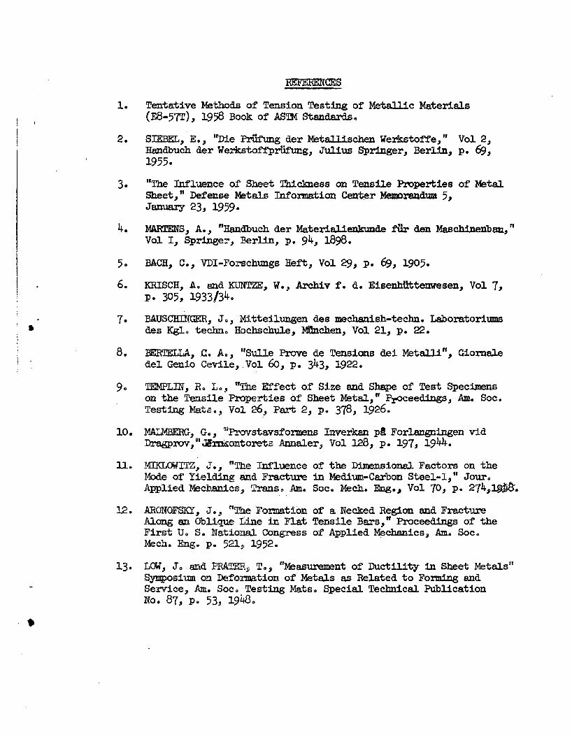
All the ~~peci.mens had. been photogridded prior to testing with thegrids spaced. at twenty to the incho Grids were put on the width surface for specimen thicknesses of J/ 8" or less and on both the width andthickness surfa.ces for specimen thicknesses of 1/411 and 1/2", seeFigure 2. As shown on this figure, two local strains, name~ thj widthand longitUdinal. strains, could easi~ be measured on al.l spec:qgens andthe thickness strain couJ.d be measured on the larger speciJDenso On thethinner Spec1DeDS the average thickness strains could be measured di~
rect~, with a micrometero Furthermore, aDy one strain can be calculated from the other two, since because of constancy of volume, the smnof the principal. strains is zero.
RESULTS AND DISCUSSION OF RESULTS
Since the distance between grids on a longitudinal. line runningalong the center of the bar was measured, the elongation for any gagel.Emgth could be determined. Plots of elongation versus various combinations of gage length and area were constructed and observations aremade. The idealized picture of tensile deformation is that a testpiece contracts uniformly in the transverse directions as it elongates 0
This lmiform deformation continues until a maximum in the load. isreached. /'l t hL;noi nt, further deformation becomes limited solely toQ r(':~lrjci·'.:c ]KH'!·j'on OJ' ',.Le test; piece termed the neck .. The size ofLh:lG l1ecl\.cd. {c:Cion rJccendG on the ·specimen dimensions. The resuJ.tsqf1\{ill be dl.scussed in -<;.,errns of this s~lified picture.
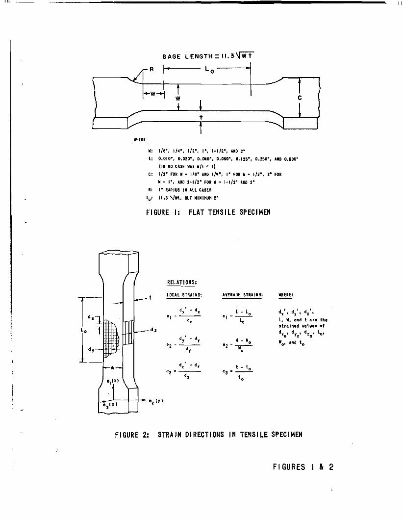
A. Effect of Gage Len§tih on EJ.o~ation
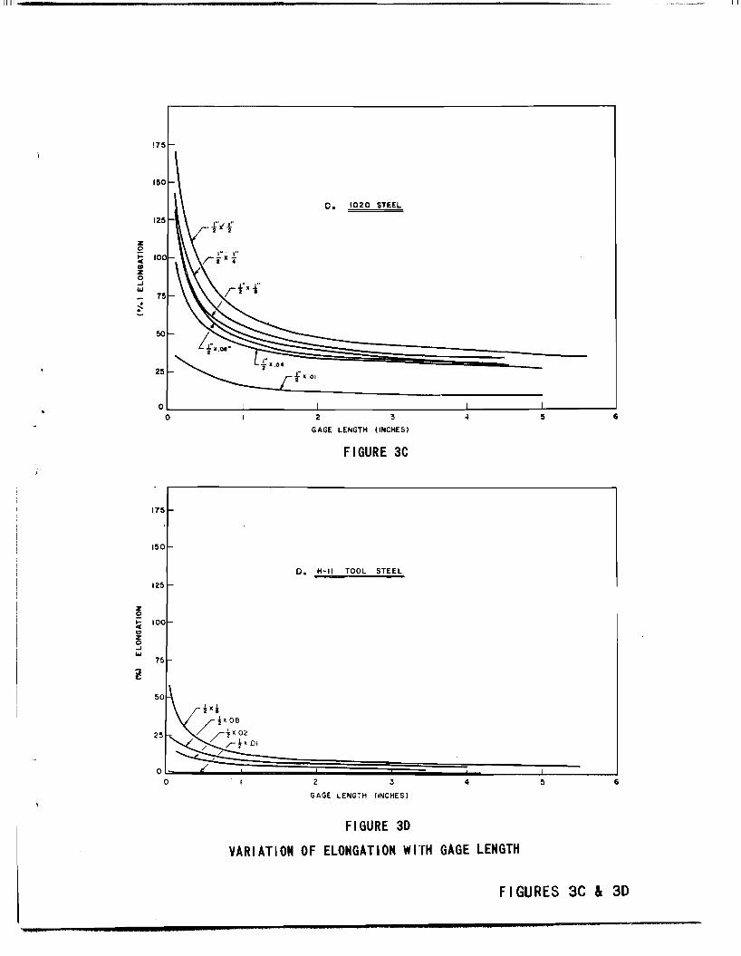
T,ypical resul.ts show-.i.ng the dependence of elongation on gage lengthfor the four materials are shown in Figures 3a to d.
In each case the elongation decreases as the gage length increases, due to the decrease i:1 the fraction of the gage length representing the necked region. There are three features of each curvewhich are wort~ of further discussion. These are the zero gage lengthelongatioD, the in:finite gage length elongation, and the variation ofelongation with gage length between these two values.
The zero gage length elongation does not seem to be a constantval.ue for a given material., but seems to decrease with specimen areaoThe smallest gage length measured is Dol inches however, and closera.greement might ha.ve been obtained if the zero gage length elongationhat been calcula:ted from measured transverse and thickness strains 0
It was not possible to obtain accurate values of thickness strain atthe fracture hOW'ever, since the fracture surface often cut through theregion of minimum thickness at an oblique angle. Furthermore, aJ.lelongation values, measured aJ.ong the center line of the spec:l.men,include a gap that :fo:r.ms between the two ha1.ves of the spec:l.men as the
~- _.-
f'ra.cture propagates from the center outward. This gap is normaJ.J.y included in staDdard elongatioo values obtained by plac1Dg the brokenhalves of the specimen together and is gene:ral.l;y greater the greaterthe specimen thickness 0 Finilly~ there is no indication that bars ofdif'ferent geometries fracture at a constant value of longitudinalstrain. Results b;y' Miklowitzll suggest that the conditions f'or f'racture are more nearly It const8.'!lllt thi("~eiSs strain.
The inf'inite ge.ge length elongation ls the elongation that a barinfinitely long -would exhibit» Md where the contribution of the neck:'Would :be effecti"\rely zero. This could aJ.so be cODs1dered to be them.aximum uniforJIl exte!i~io!li0 T'!irl.Sl val~J.e shm.il.d be independent of specimen size 0 Th.e ~,Ctlli't1 re:fn:lit8 for the longest gage lengths :measured donot show thi~, 0 If infinitely lCllrig specimens had been used" no doubtthis would, havcebeen, cibserved.l> "but t;h~ :ree.t~g effects of theshouJLderSl tel!.d to reduc,,-:; the e:l:or~g~Jtioo in this :regiooo Of' some interest a1t"e the very lcr.r elongations l'1isp~aby the Q.OIOfl1l specimens"which are even le~t"1 tn~ the ffO'tr®ins at ma.x:illmJ:m load as deteminedfrom t:rue stre2l>,8a>st:l':'I"":11tl1 testis; on rouo(Oo bars. TIme reason for this mustlie in non-tmifol'JItti:';y of' the oTlgw,al trest pi~©e. Even a variation inthicl'nesB of OoOCII)5 UIi
$ ~.itd'::~:h :.r€'pre~~Zl\ts 5~ va.r1a.tion in area for a0001011 sprecJ.meinl,9 lifrou.ld telD~d to stl"ongly localize: deformation from thestart of strl~.1ttir~" with. ('ic;:ompMying low elongation.
The V""d!JCica:tioo of' eloogf:ttion between ;z;ero 9Jlld iufi:n.ite gage lengthbas PElelm e-,xp:ressed rc)y senreral of the equ.a:tions pNI5~nted earlier. ItshoU1.d be pomted out 'tb.a;~; litJl no {;Me is t~re a ~O\IlIiI.d fi.mdamen.taJ.:reason :for der1:v:ing ~ of' the eqUtFttions,9 beyond :recognizing ,the significance of zero azllQ. mf'lllite g~e leln',gth re;loogation.
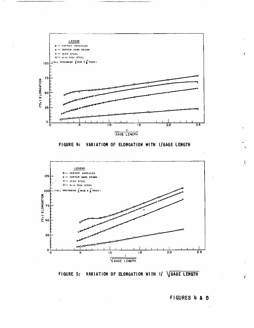
To clleck: lGO)ll)f~ o:~: 't:",e"e E!''1uc'ltio)(7,s.ll elongation h:a.s been plotted'Versus l./L a:rud 11~'r in F'igares 4 imd 5 for each matenw. at one size 0
The :resUlts sn01\>,r th":J:t; telthe:':" r~lHtio:r"sJbdp i~ valid ~r short rangesof L, b~ut th8:t neithe1" hQ>l(~,!'2 t;;'V~r"l U:iX'ge I"~ge of gage It''.ngths. InSai:lle ca.ses J) Cf'::.e or 'f:;he ot;:~er !"el~J.t::t021sh1p does g1ve a :reasonablystraigb:t JJ.Jt!le f) bi\1t f'ol" ~:m(jit:r:..e!" m"i'tc~:r1~~ or ~izre; similar resu1ts arenot fO'llD:l1Q,o It h'a\~ be~ l1loiGedl tMt ext~p'ola:tioos of' the curves to :infin!te gage liE!TJlgthl3 do lMii; yi,::,;1>3. a ,~onst1mt vsl:ue Zl alllI.d in SOll'lIe casesy-leld negative wJ.ues 21 'wm(c:tl!"ojJ::ilts out the inadequacy of the relationshi:p!3~ Plots of' th,O'J Sa"",OO d:!1t;>5:. on l'Jg=log ciQJo~tesj) Figu.re q, do notshow a, st:Jt'aight li)w~ eithml:"J) [iLQi(<J'i:;:,.g tlutt; Bertellah; equation (Eq" 6),is !Ilot COlT,:;cto
After COJtRs:idf;rl:ng tIl$ :t'Ii,li~t tM,t there is no known theoreticalbasis for expecting s. simple I'\slationsh1p j I(;l~led with experimentalcondj,tiona su<:h as end ef'fects f) possible Don~homogeneity of materialand Bpec:iJl~n'::lS~ and the oCC"UrralO!,ce of doub1e necks f) it is not surprising that no one equ.ation an.eqtl.s;tel;y' pred1<e"ts the act~ variationof elongation with gsge length.
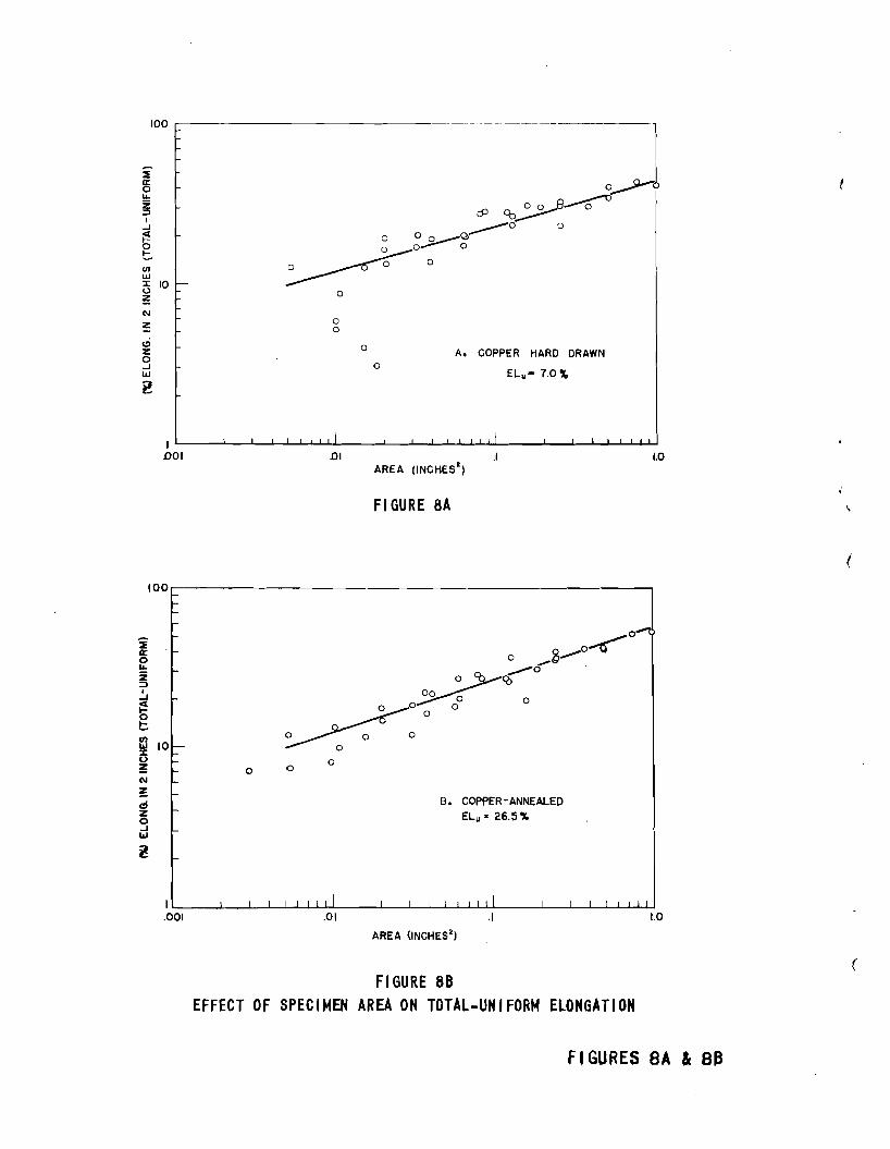
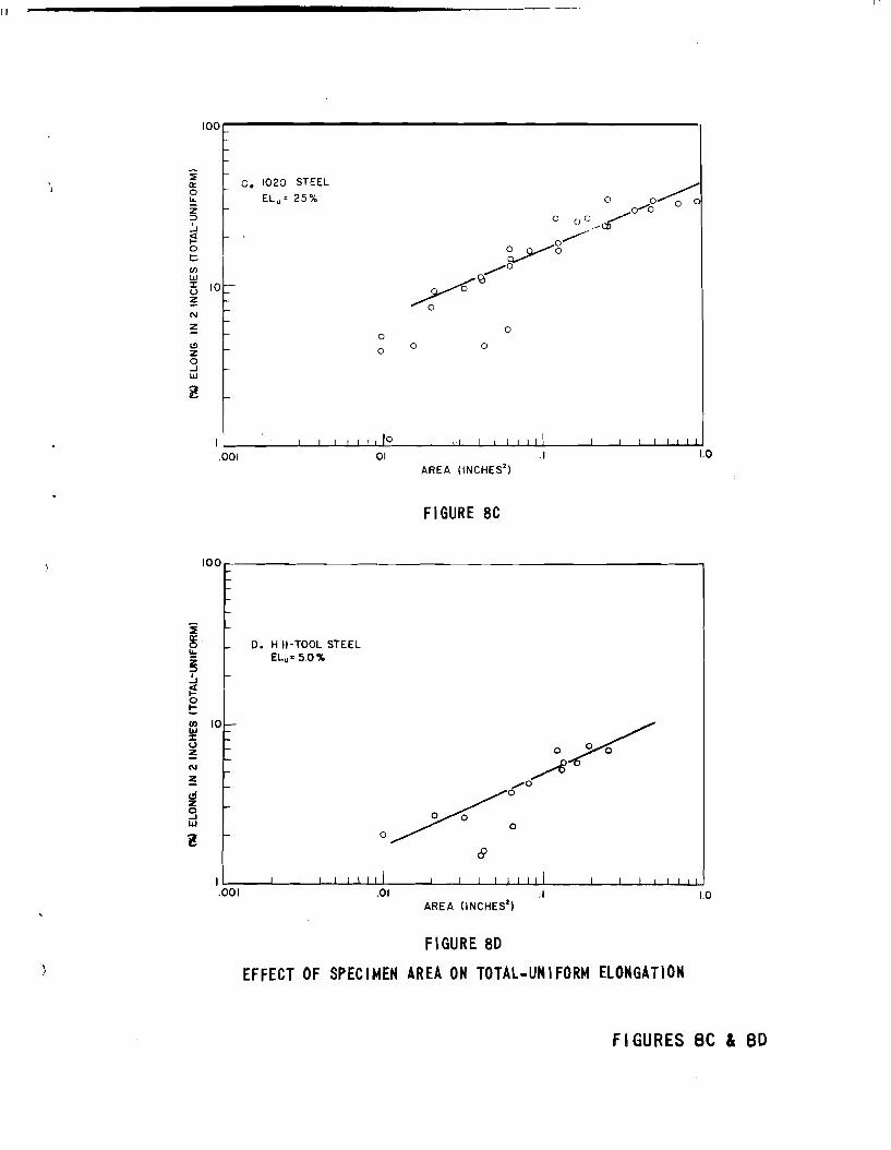
B. Effect of S12ec:i:mel'1 lu:ea on El.on5atiolll in a Fixed Gage LengthThe results plotted in Figure '7 shaw that over a range of sizes l
there is a linear relationship l:H~tween leg of elongation ill 2" and logJf' area. 1fhere 15 :::oIASid.erabl.e fScattrer however~ and at low a:reas
i
"
,
I1I1
•
J •
•
there is a deviation f'rom the linear behavior. These points representthe thinnest spec1mens, where dimensional variations would have thegreatest ef'fect. As discussed earlier, many of the elongation vaJ.uesare lower than the stra1n at :maximum load, which ~ports the viewpoint of the non-homogeneity of stra1n because of dimensional. variations.
Three equations, Eqs.5, 6, and 7, :mentioned earlier, relate elongation to some power of the area. It must be realized that for aspecimen with an area approach1ng zero, the elongation approaches theuniform elongation, and for very large specimens, the elongation in:2 inches approaches the zero gage length elongation. None of theequations approach these limits at zero or infinite gage length, whicheIlg?hasizes t..heir empiricaJ. nature. Bausch.inger·s and Bertella'sequations do approach a finite vaJ.ue at zero area however. In FiguresSa to d a...""e plotted log (El - Elu) versus log area. The unif'orm. elongations we:re detennined from true stress-strain tests. It canreadily be seen that a straight line can be drawn here aJ.so, aJ.thoughfrom a practical. viewpoint 'Penq>lin' s equation is to be pref'erred sincethe amount of scatter for the lower elongations is seemin~ reduced.
GENERAL DISCUSSION
There are two questions concerning the observed relationshipbetween elongation and area which are of interest. The first is con·cemed with the significance of area, rather than width-to-thicknessratiQ$.'or reduced section length-to-width ratio in determining elongation, and the second with the slope of the straight line portions ofthe curves in Figure '7.
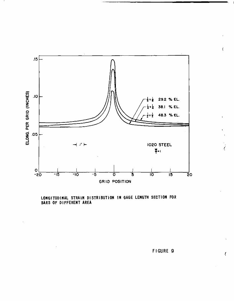
A. Significance of' Specimen ~aFigure 9 shOW's a plot of the distribution of local elongation,
measured over gage lengths of one grid spacing. It can readily beshawn that the elongation over a two inch gage length can be represented on such a plot by a horizontal. line drawn such that the areaunder it is the same as the area under the curve. Figure 9 shOW's aplot of strain distribution for three bars of the same cross-sectiongeometry, but different B..""Cas. The shapes of the curves are general1.ythe same, except that as the specimen area gets. larger, the curve getsbroader which is an indication of the larger extent of the neckedregion.. There is M effect of' size on the maximum strain. Here again,the arguments advanced in the earlier discussion are vaJ.id, in whichit was pointed out that the true zero gage length elongation vas notdetermined.. Further the local strain at the extreDlties of the gagelength section is greater for the l.a.rger area bar, because of thecloser proximity to thclmeck. .All. in aD. however, the greater elongation in 2 inches (area under the curve) for the larger area bars canbe attributed to the larger extent of necked region.
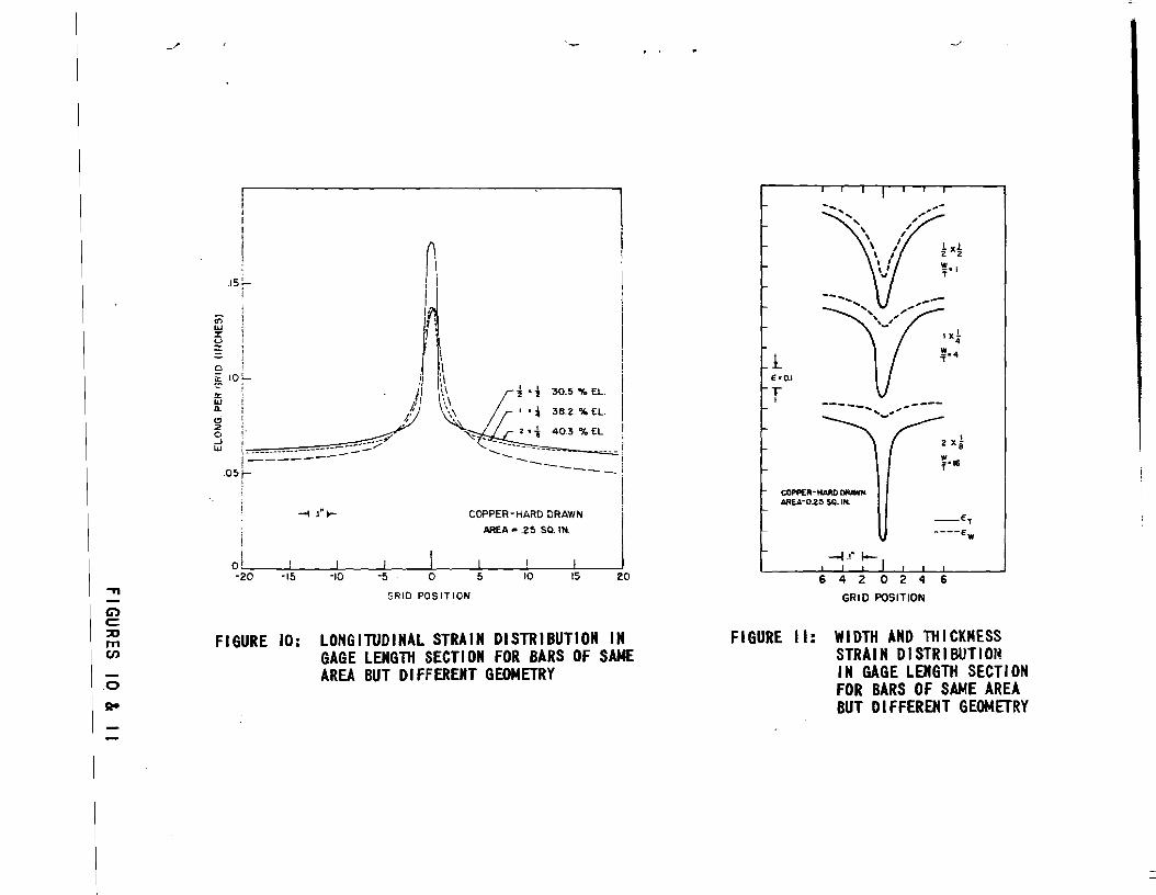
Figure 10 shows similar plots of local strain for three barshaving the same area. Within experimental accuracy, these bars havethe same elongation, and hence the same area under the curve. Noticenow that the shapes of the curves are quite different. At a 'W'i.dth-tothickness ratio (wIt) of 1, the local strain decreases uniformly withdistance from the fracture. As wIt, increases ~ there is a tenden~' for
- 7~

a. more rapid decrease of' strain with distance in a very nar:t"C1W' range inthe vicinity of the fracture, with a cJJauge to a JOOre gradual decreaseat larger distances from the f'racture. The height of the curve forhigh v /t ~tios is s'uch that at intermediate distances from the fracture it lies below~ end at large distances from the fracture it liesabove the curve for a square specimen, witl). the net result being thesame area under the cu..-rve.
Because of the constancy of volume» it is possible to break the10ngitud.i.naJ. strains into a component of' transverse or width strain8Ill.d thicmess straiD.o FtJrt;her insight into the shape of the c:urrescan possibly '"!Je fOUl:lld by ciCJlI3I61de~ the effect of width""to...th1ekDess:ratio separate1;y on 'Width Md. thicls:ness stra.1ns.. Same resul.ts areplotted 1Jnl Figure: ll.9 where '~roe st:ra.:1ns b.a.ve been used, since herethe sum of' the 'Width and t.h1cmess striUn shoUld equal the longitudinal. stm,1..'Q. The width strains were deter.mined over a ODe grid length(0005°°).9 whereas the thicknless strains were dete:rmined CNer the wholethicla:!.ess 0
The resu1.ts clearly ebeN the differ1.ng behavior for the variousw/t~so For a wit of iii the width and thickness strains are alJDostequal 0 (The hard d.rs:rM'D. coppe:r is a.ctu~ slight~ amisotropic I byvirtue of having a pref'e:r'I"ed orientation arising from cold working.)Ai3 'W/t i.ncreaaes $I there is a restraint in the width direction nnd theratio of' the thicknesl:J st:ra1Jr!l to too width st:rai.lol ilCltereases at thefracture ~ so that mst of the elolClgation at this point arises fromthe contrt"butioltll of the ·thiekness straino
B. Si~if'icelilce of' ~t.le'~ oOnlJl) in Templin's Equat100Of: soe importaltlce itS the s1.ope of the curves :in Figure 7, which
is c~terlzed "tf:f the exponent G3nGf in Templin-a equation, Eqo 7.The ~rtance of thil'l lies bt;lle fact tha;t, it is a :measure of thesensi"ti'Vity of' elongatioDl values to thicln:v~ss cmmgeso It vould tell,for e:Jf'~1.e~ wl'J.et!AeI" two m:tterlaJ"", which ~ve too same elongationvalue a.t a thic:mess of: lf8w 'Woul.dalsohave the a8mS eloll:l.gStion atsome other thickness. One 1s t~ted to look upon the exponent tOn"as a !!Ia"teldal property» '\.rhic:h C~ be determined audtahuJ.ated. Al:i:'Gtle refl.ection on thl~ problem will ShOM the f~ of such anapproach"
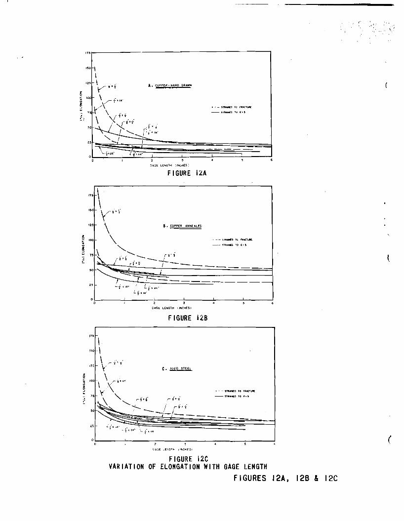
Consider the ca.se of too S~ m.l'.I.trerlall6 used :in this investigatioIil.,j) but frac·t~ at a lweI' stI"i'dno The curves of percent elongation versus gage J.ength,9 Figv.k""'e 3~ wOJUld then have a different shape.This. has iIll ef'fecrt been done by pulling va.rl.oua size ba.rrs to as <fonstBl!lt a 8t~ M poss:i.ble at the center of the neck, but below thefracture strain, a:nd neasuring the strain distributiono These resultsare plotted in Figures 12a to c together with strain distributionsfrom the f'ractu:red bars 0 It is readily a.pparent that at small gagelengths the elongations are much lower for the bars Dot fractured,but that as the gage lengths increase.9 the elcm.gatiOJl18 tor the 'twocases approach each other.9 and for an infinite gaee length they wouldpresu:m.a:bly be the same 0 Note further that for some intermediategage ~engtb sa;{ 2 inches,l/ the spread in elongation vaJ.ues between the.~est!~d largest areas is lese :for the bars pulled to a st1'8in
f
•
•
•

II II
•
less than the frac'ture strain than for the bars pulled to fracture.If these values of elonga.tion are plotted versus area as 1"Ormer~,
the resul:ts such as in Figure 13 are obt&1Ded. .Allaw1Dg for experimental sca.tter end for the fact that aJ.l bars were not pulJ.ed to ex...act~ the s~ stram, i"t can be seen that a straigb:t line is obtained,but with a lower slope than for the bars pulled to fracture. In fact,in aD extreme case, if "the bars were all pUlled to or fractured at orbefore the 11mit of uniform strain the elongation vaul.d be the samefor all bars aver all gage lengths, and the slope wouJ.d be zero on a.log"log plat of elongation versus gage length.
From these ccmsidera"tiO!ll.s, it can be seen that the exponent Un"in TempliD.is equation is no"t a general. material. property which can betabuJ.ated, but rather depends on the ductility of the specific lot ofmaterial. being tested. For two different materials with tbe sameunifol'm strain, the one having the highe:fl fracture stra.1:a would havethe greater val:ue of' the exponent IIVn tIV. Sim:ilar~, for a constant:t'racture strain, the lower the un1f'0:m strain the higher the vaJ.ue ofthis exponent. The quantity, deter.m:l.nahle fram a single tensile test,which best correlates with Templin's exponent On" is probab~ theratio of the fra.-.,"ture to the uniform strain. Unfort1me.te~, the highstrength sheet :ma.terial.s of current interest do have a law value ofuniform stra.in with moderate fracture strains, so that their elongationvaJ.ues are quite sensitive to variations in thicknesso
Co Prediction of: Per Cent ElongationIlCL maJ:J;Y' eases" it 'WOUld. be desirable to be able to predict the
elongation for any arbitrary size spec1JDen. Lacking complete data formany specimens which would allow an interpolation to be made, there isa method which suggests itself'. This is based on the concept that aconstant elongation is obtained if .Jl/L is maintained constant, assuggested by Bauschingeris equation, Eq. 5. MalJDberg found this to bevaJ.id for round bars, but not ~or rectangular bars. The results ofthis investigation support Malmberg and shaw that this is not generalJ.3true. Neverthe~es:s, under some conditions it is a good. approx1Jlla.tion.If it is valid, then at a constant vaJ.ue of elongation:
Ll "9- I.ejIi JA2
where L and A are the gage lengths and area of two different bars 1 and2. To determ1ne the elongation in a length Ie on a bar with an area.A2 from measurements OD a bar with area t!. siJnp~ meas~~l~9&"on bar lover a gage length Ll = ~ • From this relation, the
Aeelongation in a fixed gage length for ezry area bar can be calculatedfrom measurements over d.iffe:renii gage 1engths,on one bar.
Some resuJ.ts using this method have been calculated for severalsize bars of the va.r1cros materials, and are plotted in Figure 14 withthe exper1JDentaJ..ly determined results from Figure 7. In same cases, "the points do not lie on the experimeDt~ detem1ned curve, sincethe standard 2 inch elongation for the bar used lie off the curve 0 Ingeneral. the resuJ.ts ~ good, and the slopes of the experimental and
- 1-
calcu1.ated c-.:tr'TeS are the same. Deviations are noted when the elongation must be measu...""'ed over such a long gage length that either asecond necked region or end restraints are encountered.
In a practicaJ. sense, this principle could be applied to standard1/211 wide specimens. Suppose for ex~le one had available and knewthe properties of' 1/811 sheet. What elongation woul.d be eJ!;Pected inshE:et 0.08001 thic:k'l From the above relation, on.e can d.eterm.:lne 'thattlte elongation measu..red 01"1 L ~ '2-..r:JZ5 ~ 2.5 of the 1/8" sheet isthe same as the elongation in '2 incM~8n 0.080" sheet. ACC'Q&"8.tevalues should be obtained if' the areas do not dif'f'er appreciabl;y'.
SUMMARY
r;: study ha..:;: been made of the e>.ff'ect of' spec~ g88e length,width and thickness on the eloogation as ~~e:rm:1ned in ~ile test.Hard-drEtwn copperJl axmeaJ..ed copper, 102.0 s~el, and H J.t=1rl;eel werestudied.
. JUthough a number of relatiolblships have been proposed to ~la1n
the variation of' elongation 'With gage length, the results shaw thatno one :relationship adequately describes the cou:rse ot the curves.
The elongation in '2 inches is found to vary approx1mately' liDearly'with. the speci:men axea. on a log-log plot, showing agreement withTeJqplin t s equation. The ree.."!on for the dependP..nce ot elongation on:spec1JDen area. rather t.h..-.m width..to..th1ckness ratio, can be seen tram astudy of' the locaJ. 'Widt.h.\) tbick:J:less and longitudinal strains.
The sensitivity of elongation to spec:iJnen. area or thickness, asmeasured by the exponent 60n60 in Templints equation, El • CA-, is dependent on the fracture strain as well as the unitorm strain, endhence varies :from hea.t to heat of' material.o 'l'h:1s exponent is JlK)stclosely relatOd to the ra.tio of fracture strain to uniform strain.
If II"fA is mEiinta:wed constant ~ the elongation will be e;pproximate1;y constant. UBing this rel.e.tion, it is possible to est:1JDate theelongation f'or ~ size bar :f:Nm DW:!aB'l.l'I"ements made on one bar.
---e",/
- ) [)-
•,
•
•
•
1. Tentative Methods of Tension Testing of Metallic MateriaJ.s(EB-57T), 1958 Book of ASTM S1#andards.
2. SIEBEL, E., "Die Prii:t'ung der MetaJ.li.schen Werkstoffe," Vol 2,Handbuch derWerkstof'f'prlif'ung, Julius Springer, Berlin, p. 69,1955.
3. "The In:fluence of Sheet Thickness on Tensile Properties of MetalSheet, It Defense Metals In:fomation Center Memorandum 5,Ja.nuary 23, 1959.
4. MARTENS, A., "Handbuch der Material1en1tuDde fUr den Maschinenban,"Vol I, Springer, Berlin, p. 94, 1898.
50 BACH, C., VDI-Forschungs Heft" Vol 29, p. 69, 1905.
60 KRISCH, Ao and KUNT2E, W., Archiv f. d. Eisenhftttenwesen, Vol 7,p. 305, 1933/34.
7. BAUSCHINGER, J 0, Mitteilungen des mechanish-tecbn. Laboratoriumsdes KgL techno HochschuJ.e, Mtmchen, Vol 21, p. 22.
8. BE::RTE:LLA,.e.. Ao, "Sulle Prove de Tensions dei MetaJ.li", GiornaJ.edel Genio Cevile, Vol 60, p. 343, 19220
90 TEMPLIN, Ro Lo" "The Effect of Size and Shape of Test Spec1:menson the Tensile Properties of Sheet Metal, n PrOceedings, Am. Soc.Testing Mats., Vol 26, Part 2, p. 378,1926.
10. MALMBERG, Go, o~Provstavsfor.mens Inverkan pft. Forlangningen tidDragprov/'J!mkontorets Annaler, Vol 128, p. 197, 1944.
li. MIKLOWITZ, J., "The I.nf'1uence of the DimensionaJ. Fa.ctors on theMode of Yielding and Fracture in Medium-Carbon Steel-I," JouroApplied Mechan:ics, Transo Am. Soc. Mech. Eng... Vol 70, p. 2741~.
12. ARONOFSKY, J 0, ClTheFormatioIi. of a Necked Region and FractureAlong an Oblique Line in Flat Tensile Bars," Proceedings of theFirst Do S. National Congress of Applied Mechanics" Am. Soc.Mech. Eng. p. 521,1) 1952.
13. LCM, Jo and PRATER~ To, "Measurement of Ductility in Sheet Metals"Symposium. on Defo:rma.tion of MetaJ.s as Related to Forming andService, Am. Soc. Testing Mats. SpeciaJ. Teclmical PublicationNo. 87, po 53, 191.180
III II
GAGE LENGTH =II. 3 \IWTL O
t
II: I/S", 1/11", 1/2", I", 1-1/2", AND 2"t: 0.010", 0.020", 0.0_0", O.OSO", 0.125", 0.250", AND 0.600"
(IN NO CASE liAS II/t < I)
C: 1/2" FOR II • I/S" AND 1/_", I" FOR II • 1/2", 2" FORII • I", AND 2-1/2" FOR II • 1-1/2" AND 2"
R: I" RAOIUS IN ALL CASESLa: 11.3 ~BUT MINIHUH 2"
FIGURE I: FLAT TENSILE SPECIMEN
RELATIONS:
LOCAL STRA INS: AVERAGE STRA INS: IIHERE:
1d.~ dx' - dx81=~
, , ,dx ' dy , dz '
81 =dx '-0 L, II, and tare the
.traln.d valu•• of
L;dz
dx ' dy , dz ' Lo'dy' - dy
o 0 0II - II 110, and to82 = 82 = __0
dy 110
dz' - dz t - to83 =
dz83"--
to
'2 (y Ie311 I
FIGURE 2: STRAIN DIRECTIONS IN TENSILE SPECIMEN
FIGURES I & 2
175
.;-
25
A. COPPER - HARD DRAWN
42 3
GAGE LENGTH (INCHES)
o L~=:"'-...:L===::::::r=======:::r:::=====::::=:L .L-__--lo
FIGURE 3A200r--~--__1175 I
25
B. COPPE R - ANNEALED
652 3
GAGE LENGTH (INCHES)
O~_---=:::r::::::===:::r::===:::::I..- J--__--l. -.Jo
FI GURE 38
VARIATION OF ELONGATION WITH GAGE LENGTH
FIGURES 3A & 38
IIIIII ~
II
!75
zoSIIIZo~
w
1020 STEEL
:6
O~----J...-----L-------.J------l------l-------Io 2 3
GAGE LENGTH (INCHES)
FIGURE 3C
175
150
D. H-II TOOL STEEL
125
z00- 100cIIIZ0~
w75
t
GAGE LENG,H (INCHES)
FIGURE 3D
VARIATION OF ELONGATION WITH GAGE LENGTH
FIGURES 3C &30
100
z 75o~<.:lZo 50...JUl
•~
25
125
100zo~~ 75o...JIIJ
~ 50
25
LEGEND
0- COPPER ANNEALED
A - COPPER HARD DRAWN
)( - 1020 STEEL
0- H-II TOOL STEEL
(All SPECIMENS f'WIDE X "THICK)
GAGE LENGTH
FIGURE~: VARIATION OF ELONGATION WITH IIGAGE LENGTH
-----_._----_ .._-----
LEGEND
0- COPPER ANNEALED
.. - COPPER NARD DRAWN
X- '020 STEEL
0- It-II TOOL STEEL
I AL L SPEC,MEOlS {'WIDE X fTltlCK I
\J GAGE LENGTH
FIGURE 5: VARIATION OF ElONGATION WITH II \lGAGE LENGTH
FIGURES 11 & 5
(

II!III II
,)
l:izooJ...
10
1.0
GAGE LENGTH (INCHES)
10.0
FIGURE 6: VARIATION OF TOTAL-UNIFORM ELONGATION WITH GAGE LENGTH100,.....-----,...-------------------------......--
i • •0
0
0 ..!:!!1!!i.D - CO"IN .NNULID
• 0 6 - COPPI" HAltD DIlAW"
.- 1010 ITIIL
0 0- 1\-11 TOOL ITIIL
D D ~S=JD rP~~
D D __~- 6 .~~D ~.-* 66~~"""""""'0 . X~ 6 •---- . . ..~,~
.~ .• Ii
~D
D
•
D
oo
o
1.0.5.1.01.0051.0 L...-__...I._---.l.-..L......J......I.-u..J.J.---..J...-..L--!....Jl..-J...I..J...JI-L---'---l.-...L..-J.....J.....L..IU-J
.001AREA lINCHES
2)
FIGURE 7: EFFECT OF SPECIMEN AREA ON ELONGATION IN 2 INCHES
FI GURES 6 & 7
,------------------- ~----------~---100
~rr0u..Z~I
oJ
~0t-V)
UJ=c 10l)
~N
~
ciz0oJUJ
i!
oo
o
oA. COPPER HARD DRAWN
EL.- 7.0 ~
1L-_---l._--'---J...--'-.!....J,.....L...I...L..-_---JL---J...---l..--J...-I....J......L.J..J...-__.l..----l..---l......J..--'-~L.J
001 .01 .1 1.0
FIGURE 8A
(
0""'"Q.-'o~
o _(J
~~o -
00 0o 0 0 0
~oo
100r-f-
r-
2 'r-rr0...z~Ig
t::-en
10lU~:r
u~ r-N r-~ r-ei r-z0oJ f-lU
l f-
o o o
B. COPPER-ANNEALEDELu a 26.5%
I L.-...-__..L..-1---L.1--l.1----I-...L..w...J..J.I__~_L_I-'---11L....l-..I.11....L.1....1-,---1_--J.1_--l-....L-....L.....L....I-L....L...I
.001 .01 .1 1.0
AREA (INCHES')
FIGURE 88EFFECT OF SPECIMEN AREA ON TOTAL-UNIFORM ELO"GATION
FIGURES SA " 8B
(
100,.---------------------------·
II
~ c. 1020 STEEL
~ El u • 25%z:::)
~~ ~at:enlJJ
G 101-~l\J
Z
lliza...Jw
I-
oo
oo 0
I '--_---'-_-l-..........-l-...........L'..L'LI,o=-_....l.-----"J'L.....-.l..-'L....l.....J."....l'....l'...l.-1 __,L..-_.l..-'...l.-.L....L...l...J'-W
.001 .01 .1 1.0AREA (INCHES')
FIGURE 8C
100~~
~
~Q:
D. H II-TOOL STEELaLl-
Elu ' 5.0%~~0:[f-a!:III 101--w:J:c.>~ I-l\J
~
<!iz I-9I&J
i! I-
)
6'
I ':'::":__-1....-'........J..'---l_..L.-I'.....J'wIUI....l1__W'L-....L-L.....L....J...J.....Ll..L-I__...I........'_...I-'...l-.L.l..LLlJ.001 .01 .1 1.0
AREA llNCHES')
FIGURE 80
EFFECT OF SPECIMEN AREA ON TOTAL-UNIFORM ELONGATION
FIGURES 8e &80
.15
----------------------. I
-(/)w .10%: illt 29.2 % EL.uz
~Ilt 38.1 %EL.0a:: I I 48.3 % EL.C)
IIlI
a:1LIQ.
<!J .05z9w -l .1" I- 1020 STEEL
'-I ,.\
o-2·'::::0--~:---~~-:--=----~--~--~-----.l-----J20
GRID
LONGITUDINAL STRAIN DISTRIBUTION IN GAGE LENGTH SECTION FORBARS OF DIFFERENT AREA
FIGURE 9(
.15 :i
o~ .10l~ !a:....Q.
~ !~ i'. -----------------=.-::-.:::::;:;;;'
1------05f-
1
30.5"" EI..
38.Z .", Elo
40.3 0;. El
.............. ....... _ I
----_iCOPPER-HARD DRAWNAREA-0025 $C. IN.
COPPER-HARD DRAWN
AREA s .Z5 SQ. IN.
G)c:::::0rnen
!0::::1 :-----:';-_~,:::_--:!,:---_!:l--_!:,---,l:,:-----':':----20 -15 -10 -5 0 5 10 15 20
GRID P~S IT ION
FIGURE 10: LONGITUDINAL STRAIN DISTRIBUTION INGAGE LENGTH SECTION FOR BARS OF SAMEAREA BUT DIFFERENT GEOMETRY
6420246
GRID POSITION
FIGURE II: WIDTH AND THICKNESSSTRAIN DISTRIBUTIONIN GAGE LENGTH SECTIONFOR BARS OF SAME AREABUT 01 FFERENT GEOMETRY
1; ••
,7>_------------------------,
'>0
A. COPPEf'-HARD DRAWN
-- - StRAIN[O TO .It.acnlll(- STflAllilO 10 if.)
GAGE LENGTii : it'tCHES !
FIGURE 12A
• -,- HIlMII[O rc "ACT'"
-- 'STfilAI'C" TO E.'
B. COPPE~ AN hE ALED
>0 ~::::=~=r,.._====~=_--_-_-_-_----_-~=__=_-_-~-._--\2> Lf· "" ['f. o~r.•...
'00
12>
oO~---....L---~---_____:.----~---~---....J
GAGE LEhGTH IlhCHES)
FIGURE 128
,7>
c. 1020 STEEr...
- - - " .....0 Ta .AACTIJllI(
- tnAl/llll.O TO ".S
0
0
'" ----' ~ ~:_-----l (
FIGURE 12CVARIATION OF ELONGATION WITH GAGE LENGTH
FIGURES 12A, 126 & 12C

11,111II
100 r---------
1020 STEEL
........ ---STRAINED TO FRACTURE"", - - _
.. _......... 0 6.............. ~~--
-- _ 6 ,~
-0 '-STRAINED TO f - 0.5enwx'":!!:N
Z 10
c)z0..JW
i!
1.0.1.01
1L....-_......J..._..I.-..J-..J-J.......l-.u..J__......L..._..l....-...L-.LJ.....l...Jw..J.__....J..._.l....-..1-.L.....L...L.J..w
.001
FIGURE 13: VARIATION OF ELONGATION IN 2 INCHES WITH SPECIMEN AREA
\ 100 r------- --- ---"'-'- --- ----------------
v - i. *o - i.t4 -!.!o - t· t
H-II TOOL STEEL
9_'1___
V -~
----;~ ~~O ._~ _____
COPPER ANNEALED~ v.____ ____~_.---ei v v
1020 STEEL ~Bc ;______
4- V
COPPER HARD DRAWN ~zo....et
~ 109w
.01I L...--_......L_..I.-....L..-...l.....J.....l....I...I..J__......L_..I.-....L..-...l.....J.....l...L...I...l__.....L.._.1--..I.-..l...J......I-'.........'
,001
FIGURE IIJ: CALCULATED VARIATION OF ELONGATION IN 2 INCHES WITHSPEC IMEN AREA
FIGURES 13 & III