Embed Size (px)
Citation preview

ATSC A/350:2019 Guide to the Link-Layer Protocol 19 July 2019
i
ATSC Recommended Practice: Guide to the Link-Layer Protocol
(A/350)
Doc. A/350:2019 19 July 2019
Advanced Television Systems Committee 1776 K Street, N.W. Washington, D.C. 20006 202-872-9160

ATSC A/350:2019 Guide to the Link-Layer Protocol 19 July 2019
ii
The Advanced Television Systems Committee, Inc., is an international, non-profit organization
developing voluntary standards and recommended practices for digital television. ATSC member
organizations represent the broadcast, broadcast equipment, motion picture, consumer electronics,
computer, cable, satellite, and semiconductor industries. ATSC also develops digital television
implementation strategies and supports educational activities on ATSC standards. ATSC was
formed in 1983 by the member organizations of the Joint Committee on Inter-society Coordination
(JCIC): the Electronic Industries Association (EIA), the Institute of Electrical and Electronic
Engineers (IEEE), the National Association of Broadcasters (NAB), the National Cable
Telecommunications Association (NCTA), and the Society of Motion Picture and Television
Engineers (SMPTE). For more information visit www.atsc.org.
Note: The user's attention is called to the possibility that compliance with this recommended
practice may require use of an invention covered by patent rights. By publication of this standard,
no position is taken with respect to the validity of this claim or of any patent rights in connection
therewith. One or more patent holders have, however, filed a statement regarding the terms on
which such patent holder(s) may be willing to grant a license under these rights to individuals or
entities desiring to obtain such a license. Details may be obtained from the ATSC Secretary and
the patent holder.
Implementers with feedback, comments, or potential bug reports relating to this document may
contact ATSC at https://www.atsc.org/feedback/.
Revision History
Version Date
A/350 Recommended Practice approved 19 July 2019

ATSC A/350:2019 Guide to the Link-Layer Protocol 19 July 2019
iii
Table of Contents
1. SCOPE .....................................................................................................................................................1
1.1 Organization 1
2. REFERENCES .........................................................................................................................................1
2.1 Normative References 1
3. DEFINITION OF TERMS ..........................................................................................................................2
3.1 Compliance Notation 2
3.2 Treatment of Syntactic Elements 2
3.2.1 Reserved Elements 2
3.3 Acronyms and Abbreviations 2
3.4 Terms 3
3.5 Extensibility 4
4. OVERVIEW ...............................................................................................................................................4
4.1 System Architecture 4
5. GUIDELINES FOR IP HEADER COMPRESSION ...................................................................................6
5.1 IP Stream Classification Guidelines for ROHC 8
5.1.1 IP Stream Classification 8
5.1.2 Assignment of Context ID 8
5.2 Recommendations for ROHC Encoding 8
5.2.1 IP-ID Encoding 8
5.3 Recommendations for Selection of Adaptation Mode 9
5.3.1 IP Stream for Adaptation Mode 1 9
5.3.2 IP Stream for Adaptation Modes 2 and 3 9
5.4 RDT Transmission 10
5.4.1 RDT Generation 10
5.4.2 RDT Transmission Mode Selection 11
5.4.3 ROHC Initialization and Refresh 11
5.4.4 RDT Retransmission 11
6. RECOMMENDATIONS FOR PACKET ENCAPSULATION ................................................................... 11
6.1 LMT Encapsulation 11
6.2 RDT Encapsulation 11
6.2.1 Encapsulation of Catalog RDT 11
7. GUIDELINES FOR IP HEADER DECOMPRESSION ............................................................................ 12
7.1 Synchronization Between RDT and Compressed Packet Flows 12
7.1.1 RDT Synchronization in Receiver for Adaptation Mode 2 13
7.1.2 RDT Synchronization in Receiver for Adaptation Mode 3 15
7.1.3 Decompression Start without RDT Synchronization for Adaptation Mode 3 17
7.2 Guidelines for ROHC Decoding 19
7.2.1 Determination of IP-ID Behavior 19
ANNEX A : INTEROPERABILITY FUNCTIONAL TESTS ............................................................................ 20
A.1 Test Cases 20

ATSC A/350:2019 Guide to the Link-Layer Protocol 19 July 2019
iv
Index of Figures
Figure 4.1 ALP system architecture and internal identifiers. ........................................................ 5
Figure 5.1 Functional structure for IP header compression. .......................................................... 6
Figure 5.2 Combined structure for IP header compression in ATSC 3.0. ..................................... 7
Figure 5.3 Example capture of input IP stream for adaptation mode 3. ...................................... 10
Figure 6.1 Example of ALP signaling packet with Catalog RDT. .............................................. 12
Index of Tables
Table 7.1 Example of IP/UDP Stream for IP Header Compression ............................................ 13
Table 7.2 Example of Compressed IP Stream (Adaptation Mode 2) ........................................... 14
Table 7.3 Example of Static Chain for RDT ................................................................................ 15
Table 7.4 Example of Compressed IP Stream (Adaptation Mode 3) ........................................... 16
Table 7.5 Example of Static Chain and Dynamic Chain for RDT ............................................... 17
Table 7.6 Example of CRC Check of Compressed Header ......................................................... 17
Table 7.7 Example of IP Header Compression (Without UDP Checksum) ................................ 18
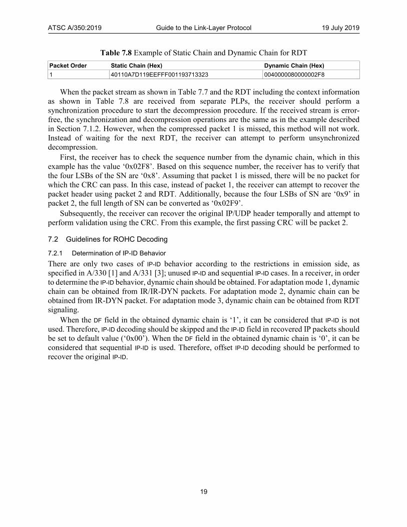
Table 7.8 Example of Static Chain and Dynamic Chain for RDT ............................................... 19
Table A.1.1 List of Interoperability Functional Tests .................................................................. 20

ATSC A/350:2019 Guide to the Link-Layer Protocol 19 July 2019
1
ATSC Recommended Practice: Guide to the Link-Layer Protocol (A/350)
1. SCOPE
This document provides recommended practices for the ATSC Link-layer Protocol (ALP) standard
specified by A/330 [1].
1.1 Organization
This document is organized as follows:
• Section 1 – Outlines the scope of this document and provides a general introduction.
• Section 2 – Lists references and applicable documents.
• Section 3 – Provides a definition of terms, acronyms, and abbreviations for this document.
• Section 4 – Overview of ALP system.
• Section 5 – Guidelines for IP Header Compression.
• Section 6 – Recommendations for Packet Encapsulation.
• Section 7 – Guidelines for IP Header Decompression.
• Annex A – Interoperability Functional Tests.
2. REFERENCES
All referenced documents are subject to revision. Users of this Standard are cautioned that newer
editions might or might not be compatible.
2.1 Normative References
The following documents, in whole or in part, as referenced in this document, contain specific
provisions that are to be followed strictly in order to implement a provision of this Standard.
[1] ATSC: “ATSC Standard: Link-Layer Protocol,” Doc. A/330:2019, Advanced Television
System Committee, Washington, D.C., [approval date]. (Work in process.)
[2] ATSC: “ATSC Standard: Physical Layer Protocol,” Doc. A/322:2018, Advanced Television
Systems Committee, Washington, D.C., 26 December 2018.
[3] ATSC: “ATSC Standard: Signaling, Delivery, Synchronization, and Error Protection,” Doc.
A/331:2019, Advanced Television Systems Committee, Washington, D.C., [approval date].
(Work in process.)
[4] IEEE: “Use of the International Systems of Units (SI): The Modern Metric System,” Doc. SI
10, Institute of Electrical and Electronics Engineers, New York, N.Y.
[5] IETF: “Internet Protocol,” Doc. STD05 (originally RFC 791), Internet Engineering Task
Force, Reston, VA, September 1981.
[6] IETF: “User Datagram Protocol,” Doc. STD06 (originally RFC 768), Internet Engineering
Task Force, Reston, VA, August 1980.
[7] IETF: RFC 3095: “RObust Header Compression (ROHC): Framework and four profiles: RTP,
UDP, ESP, and uncompressed”, Internet Engineering Task Force, Reston, VA, July 2001.
http://tools.ietf.org/html/rfc3095.
[8] IETF: RFC 4815: “RObust Header Compression (ROHC): Corrections and Clarifications to
RFC 3095”, Internet Engineering Task Force, Reston, VA, February 2007.
http://tools.ietf.org/html/rfc4815.

ATSC A/350:2019 Guide to the Link-Layer Protocol 19 July 2019
2
[9] IETF: RFC 5795: “The RObust Header Compression (ROHC) Framework”, Internet
Engineering Task Force, Reston, VA, March 2010. http://tools.ietf.org/html/rfc5795.
3. DEFINITION OF TERMS
With respect to definition of terms, abbreviations, and units, the practice of the Institute of
Electrical and Electronics Engineers (IEEE) as outlined in the Institute’s published standards [4]
should be used. Where an abbreviation is not covered by IEEE practice or industry practice differs
from IEEE practice, the abbreviation in question will be described in Section 3.3 of this document.
3.1 Compliance Notation
This section defines compliance terms for use by this document:
should – This word indicates that a certain course of action is preferred but not necessarily
required.
should not – This phrase means a certain possibility or course of action is undesirable but not
prohibited.
3.2 Treatment of Syntactic Elements
This document contains symbolic references to syntactic elements used in the audio, video, and
transport coding subsystems. These references are typographically distinguished by the use of a
different font (e.g., restricted), may contain the underscore character (e.g., sequence_end_code) and
may consist of character strings that are not English words (e.g., dynrng).
3.2.1 Reserved Elements
One or more reserved bits, symbols, fields, or ranges of values (i.e., elements) may be present in
this document. These are used primarily to enable adding new values to a syntactical structure
without altering its syntax or causing a problem with backwards compatibility, but they also can
be used for other reasons.
The ATSC default value for reserved bits is ‘1’. There is no default value for other reserved
elements. Use of reserved elements except as defined in ATSC Standards or by an industry
standards setting body is not permitted. See individual element semantics for mandatory settings
and any additional use constraints. As currently-reserved elements may be assigned values and
meanings in future versions of this Standard, receiving devices built to this version are expected
to ignore all values appearing in currently-reserved elements to avoid possible future failure to
function as intended.
3.3 Acronyms and Abbreviations
The following acronyms and abbreviations are used within this document.
ALP – ATSC Link-layer Protocol
ATSC – Advanced Television Systems Committee
CID – Context Identifier
CRC – Cyclic Redundancy Check
DF – Don’t Fragment (a flag in IPv4 header)
ID – IDentifier
IETF – Internet Engineering Task Force
IP – Internet Protocol

ATSC A/350:2019 Guide to the Link-Layer Protocol 19 July 2019
3
IPv4 – Internet Protocol version 4
IR – Initialization and Refresh
IR-DYN – IR Dynamic
LLS – Low Level Signaling
LMT – Link Mapping Table
LSB – Least Significant Bit
MPEG – Moving Picture Experts Group
MSB – Most Significant Bit
PHY – PHYsical (layer)
PID – Packet Identifier
PLP – Physical Layer Pipe
RAP – Random Access Point
RDT – ROHC-U Description Table
RF – Radio Frequency
RFC – Request For Comment (IETF standard)
ROHC – RObust Header Compression
ROHC-U – ROHC–Unidirectional mode
SID – Sub-stream IDentifier
SN – Sequence Number
TS – Transport Stream
TV - TeleVision
UDP – User Datagram Protocol
3.4 Terms
The following terms are used within this document.
Additional Header – An Additional Header is part of the ALP packet header. The presence of an
Additional Header depends on the specific field values of the Base Header.
Base Header – A Base Header is part of the ALP packet header. A Base Header is always included
in the header of an ALP packet and is the first part of an ALP packet.
Broadcast Stream – The abstraction for an RF channel which is defined in terms of a carrier
frequency centered within a specified bandwidth.
Catalog RDT – A type of RDT delivery that contains the context data for multiple ROHC/ALP
streams and can be carried in a robust signaling PLP. Thus, it can supply multiple RDTs for
multiple ALP streams.
Context – RFC 3095 [7] describes Context, as used herein, in the following manner: ‘The context
of the compressor is the state it uses to compress a header. The context of the decompressor is
the state it uses to decompress a header. Either of these or the two in combination are usually
referred to as “context,” when it is clear which is intended. The context contains relevant
information from previous headers in the packet stream, such as static fields and possible
reference values for compression and decompression. Moreover, additional information
describing the packet stream is also part of the context, for example information about how the
IP Identifier field changes and the typical inter-packet increase in sequence numbers or
timestamps.’

ATSC A/350:2019 Guide to the Link-Layer Protocol 19 July 2019
4
Discrete RDT – A type of RDT delivery that is carried exclusively within the ALP stream that it
supports. This approach is consistent with RFC 3095 [7] (ROHC), wherein the context is
always carried within the related IP stream.
Extension Header – An Extension Header is part of the ALP packet header. The presence of an
Extension Header depends on the specific field values of the Additional Header.
IP-ID – Identification field of an IPv4 packet.
multicast – (verb) To send data across (e.g., an IPv4) network to many recipients simultaneously;
(noun) A set of data sent across (e.g., an IPv4) network to many recipients simultaneously.
Network Layer Packet – A Network Layer Packet is a source packet in the protocol of the data
to be transported, e.g., an MPEG-2 Transport Stream packet or an Internet Protocol packet.
Null Packet – An MPEG-2 TS packet with PID equal to 0x1FFF.
Real Time Service RAP – A Real Time Service Random Access Point is defined as a point in the
delivery of the data required to start a Real Time Service, at which point a receiver can acquire
that Service with minimal delay.
reserved – Set aside for future use by a Standard.
Service – A collection of media components presented to the user in aggregate; the components
can be of multiple media types; a Service can be either continuous or intermittent; a Service
can be Real Time or Non-Real Time; a Real Time Service can consist of a sequence of TV
programs.
3.5 Extensibility
The protocols specified in the present standard are designed with features and mechanisms to
support extensibility. Receiving devices are expected to disregard reserved values and
unrecognized or unsupported table types.
4. OVERVIEW
4.1 System Architecture
Figure 4.1 shows the ALP system architecture and related identifiers in emission side.

ATSC A/350:2019 Guide to the Link-Layer Protocol 19 July 2019
5
IP Stream IP StreamIP Stream
ALP
ALP Gen. #1ALP Gen. #0
Upper Layer
PHY
PLP #1
PLP_ID
• • • • • •
ROHC Stream
LMT
IP Header Compression
(ROHC Channel #1)
Encapsulation
ALP Stream #1
Encapsulation
ROHC Stream
IP Header Compression
(ROHC Channel #0)
Encapsulation EncapsulationEncapsulation
• • • • • •
PLP #0
ALP Stream #0
RDTRDT
Cata
log R
DT
ALP Gen. #k
ROHC Stream
IP Header Compression
(ROHC Channel #k)
Encapsulation EncapsulationEncapsulation
PLP #k
ALP Stream #k
RDT
Dis
trete
RD
T
• • •
CID0
CIDMAX
CID0
CIDMAX
CID0
CIDMAX
• • • • • • • • •
Sub-stream ID (SID)
• • • • • •
Sub-stream ID (SID)Sub-stream ID (SID)
• • •
PLP_ID PLP_ID
IP Address /Port Number
IP Address /Port Number
IP Address /Port Number
Data Source
Data Source
Data Source
Data Source
Data Source
Data Source
Data Source
Data Source
Data Source
Data Source
Data Source
Data Source
LMT
Figure 4.1 ALP system architecture and internal identifiers.
One or more ALP streams can be delivered from an entire ALP generator. However, only a
single ALP stream is delivered to each Physical Layer Pipe (PLP). To generate ALP streams,
multiple component ALP generators can be configured, with one ALP generator for each ALP
stream. The ALP stream from each component ALP generator should be delivered to its unique
PLP. Therefore, the PLP ID can be used as the ALP Stream ID and component ALP generator ID.
The RObust Header Compression (ROHC) framework defines channels to identify the
compressed packet flow. In ATSC 3.0, a single ROHC channel should be configured in an ALP
stream. Therefore, the PLP ID can be mapped to an ROHC channel number.
ATSC A/350:2019 Guide to the Link-Layer Protocol 19 July 2019
6
5. GUIDELINES FOR IP HEADER COMPRESSION
In this section, several guidelines and recommendations are provided for the use of IP header
compression.
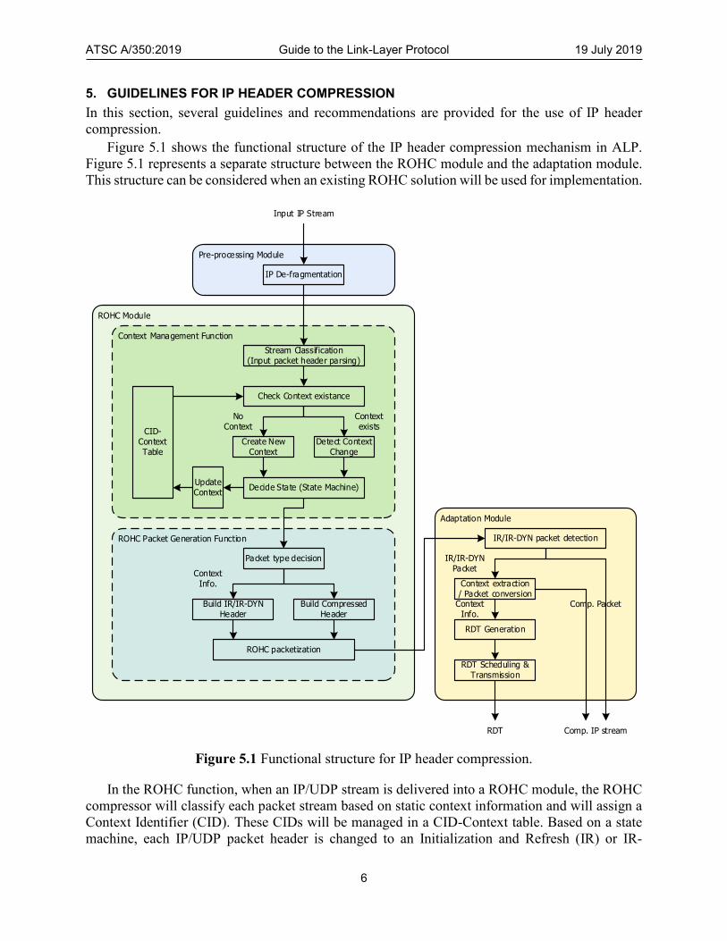
Figure 5.1 shows the functional structure of the IP header compression mechanism in ALP.
Figure 5.1 represents a separate structure between the ROHC module and the adaptation module.
This structure can be considered when an existing ROHC solution will be used for implementation.
ROHC Module
Pre-processing Module
IP De-fragmentation
Adaptation Module
IR/IR-DYN packet detection
RDT Scheduling & Transmission
RDT Generation
Context extraction / Packet conversion
RDT Comp. IP stream
Input IP Stream
IR/IR-DYN Packet
Comp. PacketContext Info.
ROHC Packet Generation Function
Packet type decision
ROHC packetization
Build Compressed Header
Build IR/IR-DYN Header
Context Management Function
Stream Classification (Input packet header parsing)
Detect Context Change
Update Context
Create New Context
Check Context existance
CID-ContextTable
Decide State (State Machine)
No Context
Context exists
Context Info.
Figure 5.1 Functional structure for IP header compression.
In the ROHC function, when an IP/UDP stream is delivered into a ROHC module, the ROHC
compressor will classify each packet stream based on static context information and will assign a
Context Identifier (CID). These CIDs will be managed in a CID-Context table. Based on a state
machine, each IP/UDP packet header is changed to an Initialization and Refresh (IR) or IR-

ATSC A/350:2019 Guide to the Link-Layer Protocol 19 July 2019
7
Dynamic (IR-DYN) packet or is encoded to a compressed header. The ROHC stream consists of
these IR, IR-DYN and compressed packets.
The adaption module detects the IR and IR-DYN packets from the ROHC packet flow and
extracts the context information. The static chain and dynamic chain can be extracted from the IR
packets, and the dynamic chain can be extracted from the IR-DYN packets. After extracting the
context information, each IR and IR-DYN packet is converted to a compressed packet according
to the configured adaptation mode. Each converted compressed packet is included and transmitted
inside the ROHC packet flow in the same order as the IR or IR-DYN packet that it replaced.
Context information is contained in the ROHC-U Description Table (RDT) which is encapsulated
in a link layer signaling packet.
Combined IP Header Compression Modulefor ATSC 3.0
Signaling Generation Function
Context Management Function
IP De-fragmentation
Stream Classification (Input packet header parsing)
Detect Context Change
Update Context
Create New Context
Check Context existance
CID-ContextTable
Decide State (State Machine)
RDT Scheduling & Transmission
RDT Generation
RDT Comp. IP stream
Input IP Stream
No Context
Context exists
ROHC Packet Generation Function
Packet type decision
ROHC packetization
Build Compressed Header
Build IR/IR-DYN Header
Context Info.
Figure 5.2 Combined structure for IP header compression in ATSC 3.0.
From the implementation point of view, the adaptation module can be merged with the ROHC
module. Figure 5.2 shows the combined structure which generates the RDT, including context

ATSC A/350:2019 Guide to the Link-Layer Protocol 19 July 2019
8
information, instead of IR or IR-DYN packet by the ROHC compressor. The adaptation mode
configuration determines whether the context information is included in the RDT or ROHC
packets. Other than the above exception, the other existing ROHC functionality can be reused.
5.1 IP Stream Classification Guidelines for ROHC
5.1.1 IP Stream Classification
ALP needs to classify the input IP stream (synonymous with the term ‘UDP/IP stream’ also used
in this section). In this section, several guidelines for input IP stream classification are provided.
An IP stream should be classified based on the IP address and port number. IP packets can be
considered to belong to the same IP stream when all of the IP packets have the same combination
of source IP address, destination IP address, source UDP port, and destination UDP port. For the
same IP/UDP stream, the same CID should be assigned.
According to the A/331 specification [3], LLS is transported in IP packets with address
224.0.23.60 and destination port number 4937. LLS packets should remain uncompressed.
5.1.2 Assignment of Context ID
As specified in RFC 3095 [7], in the ROHC UDP profile (0x0002), each UDP/IP stream is assigned
a CID. The same CID should not be assigned to different UDP/IP streams (i.e. static context
information). However, the CID for a given UDP/IP stream can optionally be changed. When the
CID for a given UDP/IP stream needs to be changed, it is strongly recommended that the CID
should be changed during the ROHC compressor’s IR state. The CIDs are distinct for each ROHC
channel. For example, CID ‘0’ over ROHC channel 1 and CID ‘0’ over ROHC channel 2 do not
refer to the same context.
For packets with a particular CID value, the UDP Sequence Number (UDP SN) generated by
the ROHC compressor is required to increment by exactly one for each successive packet in the
stream (see RFC 3095 [7], Sections 5.11.3 and 5.11.4).
Based on the ROHC packet structure, when there is no CID byte in the ROHC packet, it means
that the packet has been assigned CID ‘0’. CID ‘0’ is assigned for the most common UDP/IP
stream in each PLP.
5.2 Recommendations for ROHC Encoding
In this section, recommendations and examples of ROHC encoding are provided.
5.2.1 IP-ID Encoding
According to the restriction of the IP-ID field in A/331 [3], it can be considered that there are only
two behaviors of IP-ID in the ROHC module; unused IP-ID and sequential IP-ID cases. Random IP-ID
should not be used.
5.2.1.1 Unused IP-ID Case
When IP fragmentation is not present, all IP-ID values of incoming IP packets are always ‘0x00’,
and the value of the DF field is always ‘1’. In this case, IP-ID is not be encoded in ROHC compressor,
and the receiver will not care about the IP-ID field. The context value of IP-ID should be set to ‘0x00’.
The context information of IP-ID is never updated. The context value of the DF field in dynamic
chain should be set to ‘1’.

ATSC A/350:2019 Guide to the Link-Layer Protocol 19 July 2019
9
5.2.1.2 Sequential IP-ID Case
When IP fragmentation is either present or its presence is unknown, the IP-ID values of incoming
IP packets increase monotonically, and the value of the DF field is always ‘0’. Even though the
fragmented packets are reassembled prior to the ROHC module, the IP-ID fields should be
compressed. In this case, IP-ID should be encoded with the offset IP-ID encoding scheme. The
context of IP-ID should be updated based on the offset IP-ID encoding scheme as specified in RFC
3095 [7] Section 4.4.5. The context value of the DF field in dynamic chain shall be set to ‘0’.
5.3 Recommendations for Selection of Adaptation Mode
This section presents several guidelines about stream classification and context behavior of an IP
stream in the selection of the appropriate adaptation mode.
5.3.1 IP Stream for Adaptation Mode 1
In the emission side, when a broadcast channel is configured with a single PLP, and the IP header
compression module is implemented as a separate structure such as in the example of Figure 5.1,
adaptation mode 1 should be used. Adaptation mode 1 operation is similar to the original operation
of ROHC, and all IP streams are acceptable.
5.3.2 IP Stream for Adaptation Modes 2 and 3
In the emission side, when a broadcast channel is configured with a single PLP, and the IP header
compression module is implemented as a combined structure such as in the example of Figure 5.2,
adaptation mode 2 or 3 can be used. Additionally, for a broadcast service, when a separate
signaling PLP is configured, adaptation mode 2 or 3 can be used. In these situations, when the
context is updated frequently, adaptation mode 2 can be used. When the context is updated rarely,
adaptation mode 3 can be selected.
For an IPv4 stream, if IP address and port number are useful only for such stream, adaptation
mode 3 can be selected. Figure 5.3 shows an example of an input IP packet stream. In this IP
stream, IP-ID is unused and the dynamic context information never changes except for SN. In this
case, adaptation mode 3 can be selected. Adaptation mode 3 is the most efficient among the three
adaptation modes.

ATSC A/350:2019 Guide to the Link-Layer Protocol 19 July 2019
10
Figure 5.3 Example capture of input IP stream for adaptation mode 3.
5.4 RDT Transmission
5.4.1 RDT Generation
When the emission side operates in adaptation mode 1 or adaptation mode 2, context_config should
be set to ‘0’ or ‘1’, respectively. When the emission side operates in adaptation mode 3, the
context_config should be set to ‘2’ or ‘3’ based on the RDT structure as described in Section 7.1.2 of
A/330 [1].
ATSC A/350:2019 Guide to the Link-Layer Protocol 19 July 2019
11
5.4.2 RDT Transmission Mode Selection
When the Catalog RDT is used, the Catalog RDT should be transmitted via the PLP in which the
LMT is transmitted. This allows the LMT and Catalog RDT to be acquired at the same time.
5.4.3 ROHC Initialization and Refresh
The ROHC standard [7] requires periodic initialization and refresh of the context. This is related
to the IR packet generation and RDT repeat rate.
The ROHC standard specifies the periodic refresh of the context initialization. In ATSC 3.0,
only the unidirectional mode of ROHC is used, and therefore, periodic initialization should be
specified. When a periodic refresh has occurred, the related RDT should be sent immediately. In
order to send the RDT at the Real Time Service RAP, the ROHC initialization and refresh period
should be the same as the Real Time Service RAP period. If there is no shorter period for
initialization and refresh, then 5 seconds should be used as the initialization period. Therefore,
ROHC initialization should be aligned with the periodic RDT transmissions.
5.4.4 RDT Retransmission
RDT should be transmitted at a Real Time Service RAP, but it can be retransmitted between the
Real Time Service RAPs due to quick acquisition of signaling included in RDT. In this case, if the
duration of the PHY frame is shorter than the Real Time Service RAP, it is recommended that the
retransmission of RDT should be once per PHY frame. It is also recommended that the
retransmitted RDT is located in a position where it can be acquired quickly.
6. RECOMMENDATIONS FOR PACKET ENCAPSULATION
This section provides recommendations for encapsulation and packet format.
6.1 LMT Encapsulation
For efficient transmission of LMT, segmentation and concatenation should not be used for LMT.
6.2 RDT Encapsulation
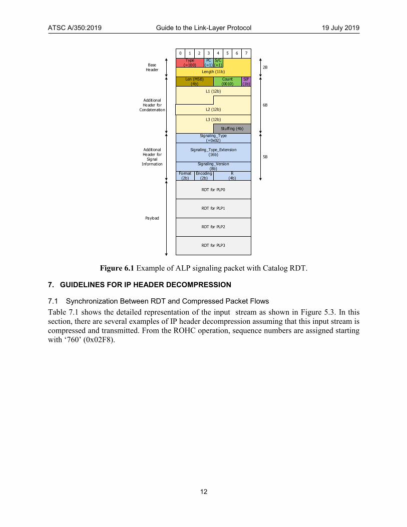
6.2.1 Encapsulation of Catalog RDT
For the Catalog RDT, concatenation should be used for multiple RDT transmissions at the Real
Time Service RAP periods. According to A/330 [1], an RDT can contain context information for
only one PLP. When concatenation is used, context information for multiple PLPs can be delivered
at the same time. Figure 6.1 shows an example of an ALP packet which contains a Catalog RDT.
In this example, it is assumed that there are four PLPs and one RDT is generated for each PLP.
The Additional Header for Signaling Information should be common for all RDTs in the payload.
ATSC A/350:2019 Guide to the Link-Layer Protocol 19 July 2019
12
Length (11b)
PC(=1)
1 2 3 4 5 6 70
6B
Type(=100)
S/C(=1)
Count(0010)
Len (MSB)(4b)
L1 (12b)
L2 (12b)
L3 (12b)
5B
Signaling_Type(=0x02)
Signaling_Type_Extension(16b)
Signaling_Version(8b)
Format(2b)
Encoding(2b)
R(4b)
Additional Header for
Signal Information
Stuffing (4b)
Additional Header for
Condatenation
BaseHeader
SIF(1b)
RDT for PLP0
RDT for PLP1
RDT for PLP2
2B
RDT for PLP3
Payload
Figure 6.1 Example of ALP signaling packet with Catalog RDT.
7. GUIDELINES FOR IP HEADER DECOMPRESSION
7.1 Synchronization Between RDT and Compressed Packet Flows
Table 7.1 shows the detailed representation of the input stream as shown in Figure 5.3. In this
section, there are several examples of IP header decompression assuming that this input stream is
compressed and transmitted. From the ROHC operation, sequence numbers are assigned starting
with ‘760’ (0x02F8).

ATSC A/350:2019 Guide to the Link-Layer Protocol 19 July 2019
13
Table 7.1 Example of IP/UDP Stream for IP Header Compression
Packet Order
IP header (Hex) UDP header (Hex) SN (Dec) SN (Hex)
1 2 3 4 5 6 7 8 9 10 11 12 13 14 15 16 17 18 19 20 21 22 23 24 25 26 27 28 29 30 31 32 33 34 35 36 37 38 39 40 41 42 43 44 45 46 47 48 49 50 ...
4500054000004000401129820A7D119EEFFF0011 4500054000004000401129820A7D119EEFFF0011 4500054000004000401129820A7D119EEFFF0011 4500054000004000401129820A7D119EEFFF0011 4500054000004000401129820A7D119EEFFF0011 4500054000004000401129820A7D119EEFFF0011 4500054000004000401129820A7D119EEFFF0011 4500054000004000401129820A7D119EEFFF0011 4500054000004000401129820A7D119EEFFF0011 4500054000004000401129820A7D119EEFFF0011 4500054000004000401129820A7D119EEFFF0011 4500054000004000401129820A7D119EEFFF0011 4500054000004000401129820A7D119EEFFF0011 4500054000004000401129820A7D119EEFFF0011 4500054000004000401129820A7D119EEFFF0011 4500054000004000401129820A7D119EEFFF0011 4500054000004000401129820A7D119EEFFF0011 4500054000004000401129820A7D119EEFFF0011 4500054000004000401129820A7D119EEFFF0011 4500054000004000401129820A7D119EEFFF0011 4500054000004000401129820A7D119EEFFF0011 4500054000004000401129820A7D119EEFFF0011 4500054000004000401129820A7D119EEFFF0011 4500054000004000401129820A7D119EEFFF0011 4500054000004000401129820A7D119EEFFF0011 4500054000004000401129820A7D119EEFFF0011 4500054000004000401129820A7D119EEFFF0011 4500054000004000401129820A7D119EEFFF0011 4500054000004000401129820A7D119EEFFF0011 4500054000004000401129820A7D119EEFFF0011 4500054000004000401129820A7D119EEFFF0011 4500054000004000401129820A7D119EEFFF0011 4500054000004000401129820A7D119EEFFF0011 4500054000004000401129820A7D119EEFFF0011 4500054000004000401129820A7D119EEFFF0011 4500054000004000401129820A7D119EEFFF0011 4500054000004000401129820A7D119EEFFF0011 4500054000004000401129820A7D119EEFFF0011 4500054000004000401129820A7D119EEFFF0011 4500054000004000401129820A7D119EEFFF0011 4500054000004000401129820A7D119EEFFF0011 4500054000004000401129820A7D119EEFFF0011 4500054000004000401129820A7D119EEFFF0011 4500054000004000401129820A7D119EEFFF0011 4500054000004000401129820A7D119EEFFF0011 4500054000004000401129820A7D119EEFFF0011 4500054000004000401129820A7D119EEFFF0011 4500054000004000401129820A7D119EEFFF0011 4500054000004000401129820A7D119EEFFF0011 4500054000004000401129820A7D119EEFFF0011 ...
93713323052C54F0 93713323052C925B 93713323052C5E8A 93713323052C3F4E 93713323052C824B 93713323052C1AE7 93713323052C9483 93713323052CF47A 93713323052CA533 93713323052C74DE 93713323052C357C 93713323052C8E86 93713323052C5728 93713323052C6BC7 93713323052C9463 93713323052CA22A 93713323052CC822 93713323052C49F4 93713323052C9892 93713323052CD18D 93713323052CE082 93713323052C41B2 93713323052CCEFD 93713323052C3B52 93713323052C23BB 93713323052CB631 93713323052CDD7B 93713323052C5871 93713323052CDEEB 93713323052CB317 93713323052C91F0 93713323052CDA39 93713323052C6032 93713323052C10E3 93713323052C42E0 93713323052CB914 93713323052CACFA 93713323052C6CEF 93713323052C42AD 93713323052CE8EE 93713323052C32D6 93713323052C5C84 93713323052C670F 93713323052C48B1 93713323052C2EBE 93713323052C49D4 93713323052C7309 93713323052C03B8 93713323052C7C3D 93713323052C5ED1 ...
760 761 762 763 764 765 766 767 768 769 770 771 772 773 774 775 776 777 778 779 780 781 782 783 784 785 786 787 788 789 790 791 792 793 794 795 796 797 798 799 800 801 802 803 804 805 806 807 808 809 ...
02F8 02F9 02FA 02FB 02FC 02FD 02FE 02FF 0300 0301 0302 0303 0304 0305 0306 0307 0308 0309 030A 030B 030C 030D 030E 030F 0310 0311 0312 0313 0314 0315 0316 0317 0318 0319 031A 031B 031C 031D 031E 031F 0320 0321 0322 0323 0324 0325 0326 0327 0328 0329 ...
7.1.1 RDT Synchronization in Receiver for Adaptation Mode 2
In this section, recommendations and an example of synchronization between RDT and
compressed packets in adaptation mode 2 are provided, including a working example.

ATSC A/350:2019 Guide to the Link-Layer Protocol 19 July 2019
14
Table 7.2 shows the detailed representation of the example compressed stream when adaptation
mode 2 is used. In this compressed stream, it is assumed that IR-DYN packets are generated at the
first packet and the 30th packet. Additionally, it is assumed that the assigned CID is ‘0’ and
compressed packets are of the UO-0 packet type.
Table 7.2 Example of Compressed IP Stream (Adaptation Mode 2)
Packet Order
SN (Hex)
CRC (8-bit)
IR-DYN Header (Hex) SN_LSB (4-bit)
CRC (3-bit)
UO-0 Header (Hex)
1 2 3 4 5 6 7 8 9 10 11 12 13 14 15 16 17 18 19 20 21 22 23 24 25 26 27 28 29 30 31 32 33 34 35 36 37 38 39 40 41 42 43 44 45 46 47 48 49 50 ...
02F8 02F9 02FA 02FB 02FC 02FD 02FE 02FF 0300 0301 0302 0303 0304 0305 0306 0307 0308 0309 030A 030B 030C 030D 030E 030F 0310 0311 0312 0313 0314 0315 0316 0317 0318 0319 031A 031B 031C 031D 031E 031F 0320 0321 0322 0323 0324 0325 0326 0327 0328 0329 ...
D7 91
F802D7004000008054F002F8 F802910040000080B3170315
9 A B C D E F 0 1 2 3 4 5 6 7 8 9 A B C D E F 0 1 2 3 4 6 7 8 9 A B C D E F 0 1 2 3 4 5 6 7 8 9 ...
6 5 2 5 3 0 1 6 7 1 3 3 0 5 3 2 0 0 0 3 1 4 2 4 6 3 5 5 2 2 0 3 1 2 0 3 4 5 0 2 5 4 5 3 7 1 7 2 ...
4E 55 5A 65 6B 70 79 06 0F 11 1B 23 28 35 3B 42 48 50 58 63 69 74 7A 04 0E 13 1D 25 32 3A 40 4B 51 5A 60 6B 74 7D 00 0A 15 1C 25 2B 37 39 47 4A ...
ATSC A/350:2019 Guide to the Link-Layer Protocol 19 July 2019
15
From this packet stream, the RDT can be generated and transmitted in packet 1 and packet 30,
and the static chain is shown in Table 7.3.
Table 7.3 Example of Static Chain for RDT
Packet Order Static chain (Hex)
1 40110A7D119EEFFF001193713323
30 40110A7D119EEFFF001193713323
When the packet stream as shown in Table 7.2 and the RDT including the context information
as shown in Table 7.3 are received from separate PLPs, the receiver should perform a
synchronization procedure to start the decompression procedure.
In case of adaptation mode 2, it is simple to synchronize between the RDT and a compressed
packet stream. First, the receiver has to check the static chain from the received RDT. Next, the
receiver has to detect the presence of an IR-DYN packet in the compressed packet stream. In this
example, the receiver can detect packet 1 as an IR-DYN packet.
Subsequently, the receiver can recover the original IP header temporally and perform
validation using the CRC. If CRC validation passes, synchronization can be considered successful.
If packet 1 is missed due to reception error, the receiver can attempt to perform decompression
as described above using packet 30. The packets which are received prior to packet 30 cannot be
decompressed in adaptation mode 2.
7.1.2 RDT Synchronization in Receiver for Adaptation Mode 3
In this section, recommendations and an example of synchronization between RDT and
compressed packets in adaptation mode 3 are provided, including a working example.
Table 7.4 shows the detailed representation of the example input stream as shown in Figure
5.3. Additionally, compressed packet headers are listed based on the input stream. In this
compressed stream, it is assumed that the assigned CID is ‘0’ and compressed packets are of the
UO-0 packet type.

ATSC A/350:2019 Guide to the Link-Layer Protocol 19 July 2019
16
Table 7.4 Example of Compressed IP Stream (Adaptation Mode 3)
PacketOrder SN (Hex) SN_LSB (4-bit) CRC (3-bit) UO-0 (Hex)
1 2 3 4 5 6 7 8 9 10 11 12 13 14 15 16 17 18 19 20 21 22 23 24 25 26 27 28 29 30 31 32 33 34 35 36 37 38 39 40 41 42 43 44 45 46 47 48 49 50 ...
02F8 02F9 02FA 02FB 02FC 02FD 02FE 02FF 0300 0301 0302 0303 0304 0305 0306 0307 0308 0309 030A 030B 030C 030D 030E 030F 0310 0311 0312 0313 0314 0315 0316 0317 0318 0319 031A 031B 031C 031D 031E 031F 0320 0321 0322 0323 0324 0325 0326 0327 0328 0329 ...
8 9 A B C D E F 0 1 2 3 4 5 6 7 8 9 A B C D E F 0 1 2 3 4 5 6 7 8 9 A B C D E F 0 1 2 3 4 5 6 7 8 9 ...
0 6 5 2 5 3 0 1 6 7 1 3 3 0 5 3 2 0 0 0 3 1 4 2 4 6 3 5 5 1 2 2 0 3 1 2 0 3 4 5 0 2 5 4 5 3 7 1 7 2 ...
40 4E 55 5A 65 6B 70 79 06 0F 11 1B 23 28 35 3B 42 48 50 58 63 69 74 7A 04 0E 13 1D 25 29 32 3A 40 4B 51 5A 60 6B 74 7D 00 0A 15 1C 25 2B 37 39 47 4A ...
From this packet stream, the RDT can be generated using packet 1 and the static chain and
dynamic chain are shown in Table 7.5.

ATSC A/350:2019 Guide to the Link-Layer Protocol 19 July 2019
17
Table 7.5 Example of Static Chain and Dynamic Chain for RDT
Packet Order Static chain (Hex) Dynamic chain (Hex)
1 40110A7D119EEFFF001193713323 004000008054F002F8
When the packet stream as shown in Table 7.4 and the RDT including the context information
as shown in Table 7.5 are received from separate PLPs, the receiver should perform a
synchronization procedure to start the decompression procedure.
First, the receiver has to check the sequence number from the dynamic chain, which in this
example has the value ‘0x02F8’. Based on this sequence number, the receiver has to verify that
the four LSBs of the SN are ‘0x8’. From Table 7.4, these packet numbers are 1, 17, 33, 49 and so
on.
Thereafter, the receiver can recover the original IP/UDP header temporally and attempt to
perform validation using the CRC. From this example, the first passing CRC will be packet 1.
Table 7.6 Example of CRC Check of Compressed Header
Packet Order UO-0 (Hex) SN_LSB (4-bit) SN (Hex) CRC (3-bit) CRC Result
1 17 33 49 ...
40 42 40 47 ...
8 8 8 8 ...
02F8 0308 0318 0328 ...
0 2 0 7 ...
Pass Fail Fail Fail ...
Based on the result shown in Table 7.6, the receiver can perform packet decompression starting
from packet 1.
7.1.3 Decompression Start without RDT Synchronization for Adaptation Mode 3
According to the UDP standard [6], UDP checksum is optional for IPv4. In this case, the UDP
checksum field should be set to ‘0x00’ as shown in Table 7.7. When UDP checksum is not used,
all the values of fields are the same except for the total length field of IP header, length field of
UDP header and SN.
The value of CRC in ROHC packet depends on the total length field of IP header, length field
of UDP header and SN. According to ROHC operation, the total length field and UDP length field
are never transmitted from compressor to decompressor. Also, SN is assigned in the ROHC
compressor. When UDP checksum is not used, RDT can be applied to any compressed packet. In
this case, the decompressor can ignore the CRC failure for the fast decompression start, and the
decompression procedure can be started at any position of the compressed packet.

ATSC A/350:2019 Guide to the Link-Layer Protocol 19 July 2019
18
Table 7.7 Example of IP Header Compression (Without UDP Checksum)
Packet Order
IP header (Hex) UDP header (Hex) SN (Hex)
SN_LSB (4-bit)
CRC (3-bit)
UO-0 Hex)
1 2 3 4 5 6 7 8 9 10 11 12 13 14 15 16 17 18 19 20 21 22 23 24 25 26 27 28 29 30 31 32 33 34 35 36 37 38 39 40 41 42 43 44 45 46 47 48 49 50 ...
4500054000004000401129820A7D119EEFFF0011 4500054000004000401129820A7D119EEFFF0011 4500054000004000401129820A7D119EEFFF0011 4500054000004000401129820A7D119EEFFF0011 4500054000004000401129820A7D119EEFFF0011 4500054000004000401129820A7D119EEFFF0011 4500054000004000401129820A7D119EEFFF0011 4500054000004000401129820A7D119EEFFF0011 4500054000004000401129820A7D119EEFFF0011 4500054000004000401129820A7D119EEFFF0011 4500054000004000401129820A7D119EEFFF0011 4500054000004000401129820A7D119EEFFF0011 4500054000004000401129820A7D119EEFFF0011 4500054000004000401129820A7D119EEFFF0011 4500054000004000401129820A7D119EEFFF0011 4500054000004000401129820A7D119EEFFF0011 4500054000004000401129820A7D119EEFFF0011 4500054000004000401129820A7D119EEFFF0011 4500054000004000401129820A7D119EEFFF0011 4500054000004000401129820A7D119EEFFF0011 4500054000004000401129820A7D119EEFFF0011 4500054000004000401129820A7D119EEFFF0011 4500054000004000401129820A7D119EEFFF0011 4500054000004000401129820A7D119EEFFF0011 4500054000004000401129820A7D119EEFFF0011 4500054000004000401129820A7D119EEFFF0011 4500054000004000401129820A7D119EEFFF0011 4500054000004000401129820A7D119EEFFF0011 4500054000004000401129820A7D119EEFFF0011 4500054000004000401129820A7D119EEFFF0011 4500054000004000401129820A7D119EEFFF0011 4500054000004000401129820A7D119EEFFF0011 4500054000004000401129820A7D119EEFFF0011 4500054000004000401129820A7D119EEFFF0011 4500054000004000401129820A7D119EEFFF0011 4500054000004000401129820A7D119EEFFF0011 4500054000004000401129820A7D119EEFFF0011 4500054000004000401129820A7D119EEFFF0011 4500054000004000401129820A7D119EEFFF0011 4500054000004000401129820A7D119EEFFF0011 4500054000004000401129820A7D119EEFFF0011 4500054000004000401129820A7D119EEFFF0011 4500054000004000401129820A7D119EEFFF0011 4500054000004000401129820A7D119EEFFF0011 4500054000004000401129820A7D119EEFFF0011 4500054000004000401129820A7D119EEFFF0011 4500054000004000401129820A7D119EEFFF0011 4500054000004000401129820A7D119EEFFF0011 4500054000004000401129820A7D119EEFFF0011 4500054000004000401129820A7D119EEFFF0011 ...
93713323052C0000 93713323052C0000 93713323052C0000 93713323052C0000 93713323052C0000 93713323052C0000 93713323052C0000 93713323052C0000 93713323052C0000 93713323052C0000 93713323052C0000 93713323052C0000 93713323052C0000 93713323052C0000 93713323052C0000 93713323052C0000 93713323052C0000 93713323052C0000 93713323052C0000 93713323052C0000 93713323052C0000 93713323052C0000 93713323052C0000 93713323052C0000 93713323052C0000 93713323052C0000 93713323052C0000 93713323052C0000 93713323052C0000 93713323052C0000 93713323052C0000 93713323052C0000 93713323052C0000 93713323052C0000 93713323052C0000 93713323052C0000 93713323052C0000 93713323052C0000 93713323052C0000 93713323052C0000 93713323052C0000 93713323052C0000 93713323052C0000 93713323052C0000 93713323052C0000 93713323052C0000 93713323052C0000 93713323052C0000 93713323052C0000 93713323052C0000 ...
02F8 02F9 02FA 02FB 02FC 02FD 02FE 02FF 0300 0301 0302 0303 0304 0305 0306 0307 0308 0309 030A 030B 030C 030D 030E 030F 0310 0311 0312 0313 0314 0315 0316 0317 0318 0319 031A 031B 031C 031D 031E 031F 0320 0321 0322 0323 0324 0325 0326 0327 0328 0329 ...
8 9 A B C D E F 0 1 2 3 4 5 6 7 8 9 A B C D E F 0 1 2 3 4 5 6 7 8 9 A B C D E F 0 1 2 3 4 5 6 7 8 9 ...
0 6 5 2 5 3 0 1 6 7 1 3 3 0 5 3 2 0 0 0 3 1 4 2 4 6 3 5 5 1 2 2 0 3 1 2 0 3 4 5 0 2 5 4 5 3 7 1 7 2 ...
40 4E 55 5A 65 6B 70 79 06 0F 11 1B 23 28 35 3B 42 48 50 58 63 69 74 7A 04 0E 13 1D 25 29 32 3A 40 4B 51 5A 60 6B 74 7D 00 0A 15 1C 25 2B 37 39 47 4A ...
From this packet stream, the RDT can be generated using packet 1. The static chain and
dynamic chain are shown in Table 7.8.
ATSC A/350:2019 Guide to the Link-Layer Protocol 19 July 2019
19
Table 7.8 Example of Static Chain and Dynamic Chain for RDT
Packet Order Static Chain (Hex) Dynamic Chain (Hex)
1 40110A7D119EEFFF001193713323 0040000080000002F8
When the packet stream as shown in Table 7.7 and the RDT including the context information
as shown in Table 7.8 are received from separate PLPs, the receiver should perform a
synchronization procedure to start the decompression procedure. If the received stream is error-
free, the synchronization and decompression operations are the same as in the example described
in Section 7.1.2. However, when the compressed packet 1 is missed, this method will not work.
Instead of waiting for the next RDT, the receiver can attempt to perform unsynchronized
decompression.
First, the receiver has to check the sequence number from the dynamic chain, which in this
example has the value ‘0x02F8’. Based on this sequence number, the receiver has to verify that
the four LSBs of the SN are ‘0x8’. Assuming that packet 1 is missed, there will be no packet for
which the CRC can pass. In this case, instead of packet 1, the receiver can attempt to recover the
packet header using packet 2 and RDT. Additionally, because the four LSBs of SN are ‘0x9’ in
packet 2, the full length of SN can be converted as ‘0x02F9’.
Subsequently, the receiver can recover the original IP/UDP header temporally and attempt to
perform validation using the CRC. From this example, the first passing CRC will be packet 2.
7.2 Guidelines for ROHC Decoding
7.2.1 Determination of IP-ID Behavior
There are only two cases of IP-ID behavior according to the restrictions in emission side, as
specified in A/330 [1] and A/331 [3]; unused IP-ID and sequential IP-ID cases. In a receiver, in order
to determine the IP-ID behavior, dynamic chain should be obtained. For adaptation mode 1, dynamic
chain can be obtained from IR/IR-DYN packets. For adaptation mode 2, dynamic chain can be
obtained from IR-DYN packet. For adaptation mode 3, dynamic chain can be obtained from RDT
signaling.
When the DF field in the obtained dynamic chain is ‘1’, it can be considered that IP-ID is not
used. Therefore, IP-ID decoding should be skipped and the IP-ID field in recovered IP packets should
be set to default value (‘0x00’). When the DF field in the obtained dynamic chain is ‘0’, it can be
considered that sequential IP-ID is used. Therefore, offset IP-ID decoding should be performed to
recover the original IP-ID.

ATSC A/350:2019 Guide to the Link-Layer Protocol 19 July 2019
20
Annex A: Interoperability Functional Tests
A.1 TEST CASES
Table A.1.1 provides essential test cases for interoperability functional tests between emission side
and receiver.
[Note: The contents of this table may be updated based on the discussion about
interoperability tests.]
Table A.1.1 List of Interoperability Functional Tests
Test No.
Test configurations IP Header Compression Encapsulation Check Point Required Test
PLP ALP input ROHC IP-ID encoding
Adapt. Mode
RDT Payload SID Mode
ALP Header
1 Single PLP
IP Stream, Packet length ≤ 2047
off N/A N/A N/A IP off BH Packet transmission/reception, Base Header
2 Single PLP
IP Stream, Packet length > 2047
off N/A N/A N/A IP off BH AH_Single Additional Header for Single Packet
1
3 Single PLP
IP Stream off N/A N/A N/A IP off BH AH_Seg. Additional Header for Segmentation
1
4 Single PLP
IP Stream off N/A N/A N/A IP off BH AH_Conc. Additional Header for Concatenation
1
5 Single PLP
IP Stream off N/A N/A N/A LMT off BH AH_Sig. (LMT)
Additional Header for Signaling, LMT
1
6 Multiple PLPs
Multiple IP streams
off N/A N/A N/A LMT
off BH
AH_Sig. (LMT)
PLP selection with LMT (PLP - addr. & port)
1, 5
IP
7 Single PLP
Multiple IP streams
off N/A N/A N/A
LMT
on BH
AH_Sig. (LMT)
Extension header for SID, IP stream selection with LMT (SID - addr. & port)
2, 3, 4, 5
IP
AH_Single
EH_SID AH_Seg.
AH_Conc.
8 Multiple PLPs
Multiple IP streams
off N/A N/A N/A
LMT
on BH
AH_Sig. (LMT)
PLP and IP stream selection with LMT (PLP - SID - addr. & port)
6, 7
IP
AH_Single
EH_SID AH_Seg.
AH_Conc.
9 Single PLP
Single IP stream with IP-ID = 0x00
on No Encoding
Mode 1 Discrete RDT
LMT
off BH
AH_Sig. (LMT)
Simple ROHC operation, Discrete RDT
1, 5 RDT AH_Sig. (RDT)
Comp. IP
10 Single PLP
Single IP stream with IP-ID = 0x00
on No Encoding
Mode 2 Discrete RDT
LMT
off BH
AH_Sig. (LMT)
Adaptation Mode 2 with Discrete RDT
9 RDT AH_Sig. (RDT)
Comp. IP
11 Single PLP
Single IP stream with IP-ID = 0x00
on No Encoding
Mode 3 Discrete RDT
LMT
off BH
AH_Sig. (LMT)
Adaptation Mode 3 with Discrete RDT
10 RDT AH_Sig. (RDT)
Comp. IP
12 Single PLP
Single IP stream
on Offset IP-ID Encoding
Mode 1 Discrete RDT
LMT off BH AH_Sig. (LMT)
9

ATSC A/350:2019 Guide to the Link-Layer Protocol 19 July 2019
21
with Sequential IP-ID
RDT AH_Sig. (RDT) Offset IP-ID encoding,
Adaptation Mode 1 with Discrete RDT Comp.
IP
13 Single PLP
Single IP stream with Sequential IP-ID
on Offset IP-ID Encoding
Mode 2 Discrete RDT
LMT
off BH
AH_Sig. (LMT)
Offset IP-ID encoding, Adaptation Mode 2 with Discrete RDT
10, 12 RDT AH_Sig. (RDT)
Comp. IP
14 Single PLP
Single IP stream with Sequential IP-ID
on Offset IP-ID Encoding
Mode 3 Discrete RDT
LMT
off BH
AH_Sig. (LMT)
Offset IP-ID encoding, Adaptation Mode 3 with Discrete RDT
11, 13 RDT AH_Sig. (RDT)
Comp. IP
15 Multiple PLPs
Multiple IP streams with IP-ID = 0x00
on No Encoding
Mode 1 Catalog RDT
LMT
off BH
AH_Sig. (LMT)
Catalog RDT via separate PLP 4, 6, 9 RDT AH_Conc. AH_Sig. (RDT)
Comp. IP
16 Multiple PLPs
Multiple IP streams with IP-ID = 0x00
on No Encoding
Mode 2 Catalog RDT
LMT
off BH
AH_Sig. (LMT)
Catalog RDT via separate PLP, Synchronization in Adaptation Mode 2
10, 15 RDT AH_Conc. AH_Sig. (RDT)
Comp. IP
17 Multiple PLPs
Multiple IP streams with IP-ID = 0x00
on No Encoding
Mode 3 Catalog RDT
LMT
off BH
AH_Sig. (LMT)
Catalog RDT via separate PLP, Synchronization in Adaptation Mode 3
11, 16 RDT AH_Conc. AH_Sig. (RDT)
Comp. IP
18 Multiple PLPs
Multiple IP streams with Sequential IP-ID
on Offset IP-ID Encoding
Mode 1 Catalog RDT
LMT
off BH
AH_Sig. (LMT)
Catalog RDT via separate PLP, Offset IP-ID encoding
12, 15 RDT AH_Conc. AH_Sig. (RDT)
Comp. IP
19 Multiple PLPs
Multiple IP streams with Sequential IP-ID
on Offset IP-ID Encoding
Mode 2 Catalog RDT
LMT
off BH
AH_Sig. (LMT)
Catalog RDT via separate PLP, Synchronization in Adaptation Mode 2, Offset IP-ID encoding
13, 16, 18
RDT AH_Conc. AH_Sig. (RDT)
Comp. IP
20 Multiple PLPs
Multiple IP streams with Sequential IP-ID
on Offset IP-ID Encoding
Mode 3 Catalog RDT
LMT
off BH
AH_Sig. (LMT)
Catalog RDT via separate PLP, Synchronization in Adaptation Mode 3, Offset IP-ID encoding
14, 17, 18
RDT AH_Conc. AH_Sig. (RDT)
Comp. IP
— End of Document —