Embed Size (px)
Citation preview

Attachment 3 – Project Description (Exhibit A) from the FLA

FINAL APPLICATION FOR LICENSE
OF MAJOR UNCONSTRUCTED PROJECT
REVISED EXHIBIT A
PROJECT DESCRIPTION
LAKE ELSINORE ADVANCED PUMPED STORAGE PROJECT
FEDERAL ENERGY REGULATORY COMMISSION PROJECT NUMBER 14227
Applicant:
THE NEVADA HYDRO COMPANY, INC. 2416 Cades Way
Vista, California 92081 (760) 599-1813
(760) 599-1815 FAX
April 2018

REVISED EXHIBIT A – PROJECT DESCRIPTION FERC Project No. 14227
Lake Elsinore Advanced Pumped Storage Project April 2018 Page A–i
Table of Contents
Page
1.0. Physical Composition, Dimensions and General Configuration of Major Structures ..... 1
1.1. Project Introductory Description ............................................................................ 1
1.2. Upper Reservoir and Associated Structures ........................................................... 9
1.2.1. Location ....................................................................................................... 9
1.2.2. Design Assumptions .................................................................................... 9
1.2.3. Characteristics ............................................................................................. 9
1.2.4. Reservoir Embankment ............................................................................. 11
1.2.5. Intake/Outlet Structure ............................................................................ 11
1.3. Penstocks .............................................................................................................. 12
1.4. Powerhouse and Associated Shafts and Chambers .............................................. 12
1.4.1. Powerhouse .............................................................................................. 12
1.4.2. Surge Chamber .......................................................................................... 14
1.4.3. Access Shaft .............................................................................................. 14
1.4.4. Vent Shaft ................................................................................................. 14
1.5. Lower Reservoir and Associated Structures ......................................................... 14
1.5.1. Lower Reservoir ........................................................................................ 14
1.5.2. Intake/Outlet Structure ............................................................................ 16
2.0. Reservoir Characteristics .......................................................................................... 17
2.1. Upper Reservoir .................................................................................................... 17
2.2. Lower Reservoir .................................................................................................... 17
3.0. Pump–Turbine and Motor–Generator Characteristics ............................................... 17
3.1. Pump-Turbines ...................................................................................................... 19
3.1.1. Runner ....................................................................................................... 19
3.1.2. Turbine Shaft ............................................................................................. 20
3.1.3. Spiral Case/Stay Ring ................................................................................ 20
3.1.4. Draft Tube ................................................................................................. 20
3.1.5. Pit Liner ..................................................................................................... 21
3.1.6. Wicket Gates ............................................................................................. 21
3.1.7. Wicket Gate Mechanism with Two Gate Servomotors ............................ 21
3.1.8. Head Cover ................................................................................................ 23
3.1.9. Bottom Ring/Discharge Ring ..................................................................... 23
3.1.10. Stationary Wearing Rings .......................................................................... 23
3.1.11. Shaft Seal................................................................................................... 23
3.1.12. Shaft Seal Lubrication ............................................................................... 24
3.1.13. Pump-Turbine Guide Bearing ................................................................... 25
3.1.14. Blow Down Equipment for Pump-Turbine ................................................ 26
3.1.15. Covers, Walkways and Railings ................................................................. 28
REVISED EXHIBIT A – PROJECT DESCRIPTION FERC Project No. 14227
April 2018 Lake Elsinore Advanced Pumped Storage Project Page A–ii
3.1.16. Monorail .................................................................................................... 28
3.1.17. Inspection and/or Installation Platform in the Draft Tube ....................... 28
3.1.18. Piping......................................................................................................... 28
3.1.19. Flow Measurement System ...................................................................... 28
3.2. Motor-Generators ................................................................................................. 28
3.2.1. Outline of Overall Construction ................................................................ 29
3.2.2. Features of Construction .......................................................................... 30
3.3. Starting .................................................................................................................. 36
3.4. Black Start Capability ............................................................................................ 36
3.4.1. Normal Day-to-Day Operations ................................................................ 37
3.4.2. Dead Bus on SCE Valley-Serrano 500 kV Transmission Line at Lake Substation ................................................................................................. 37
3.4.3. Dead Bus on SDG&E Talega-Escondido 230 kV Transmission Line at Case Springs Substation .................................................................................... 38
3.4.4. Dead Bus on both the Case Springs and Lake Substations ....................... 38
4.0. Primary Transmission Lines ...................................................................................... 38
4.1. 13.8 kV Connection ............................................................................................... 38
4.2. 500 kV Primary Connection .................................................................................. 38
5.0. Appurtenant Equipment ........................................................................................... 45
5.1. Main Penstock Valves ........................................................................................... 45
5.1.1. Housing ..................................................................................................... 45
5.1.2. Rotor Plug with Trunnions ........................................................................ 45
5.1.3. Valve Seals ................................................................................................ 45
5.1.4. Bearings ..................................................................................................... 47
5.1.5. Valve Actuator........................................................................................... 47
5.1.6. By-Pass ...................................................................................................... 47
5.1.7. Control and Monitoring ............................................................................ 48
5.1.8. Dismantling Joint ....................................................................................... 48
5.1.9. Shop Assembly and Pressure Tests ........................................................... 48
5.2. Draft Tube Bulkhead Gates ................................................................................... 49
5.3. Hoists and Cranes.................................................................................................. 49
5.4. Power Plant Mechanical Service Systems............................................................. 49
5.4.1. Ventilation ................................................................................................. 49
5.4.2. Fire Protection .......................................................................................... 49
5.4.3. Drainage and Dewatering ......................................................................... 50
5.4.4. Potable Water and Sanitary Services ........................................................ 50
5.4.5. Compressed Air Systems ........................................................................... 50
5.5. Power Plant Electrical and Control Systems ......................................................... 50
5.5.1. Power Plant Electrical Systems ................................................................. 50
5.5.2. Control Systems ........................................................................................ 51
REVISED EXHIBIT A – PROJECT DESCRIPTION FERC Project No. 14227
Lake Elsinore Advanced Pumped Storage Project April 2018 Page A–iii
6.0. Lands of the United States within Project Boundary .................................................. 51
LIST OF TABLES
Page
Table A–1: Summary of Principal Characteristics 5
Table A–2: Lake Elsinore Area-Capacity Characteristics at Various Water Levels 16
Table A–3: Upper Reservoir Characteristics 17
Table A–4: Equipment Characteristics 18
Table A–5: Motor Generator Characteristics 29
LIST OF FIGURES
Page
Figure A- 1: Regional Location Map 3
Figure A- 2: Project Facilities Location Map 4
Figure A- 3: Project Conceptual Single Line Diagram 6
Figure A- 4: Project Plan View 7
Figure A- 5: Project Profile View 8
Figure A- 6: Typical Wicket Gate Mechanism 22
Figure A- 7: Typical Wicket Gate Mechanism–Plan View 22
Figure A- 8: Typical Shaft Seal 24
Figure A- 9: Shaft Seal Lubrication Schematic 25
Figure A- 10: Typical Pump–Turbine Guide Bearings 25
Figure A- 11: Blow Down Equipment 27
Figure A- 12: Typical Seal Detail 27
REVISED EXHIBIT A – PROJECT DESCRIPTION FERC Project No. 14227
April 2018 Lake Elsinore Advanced Pumped Storage Project Page A–iv
Figure A- 13: Santa Rosa Substation Drawings 40
Figure A- 14: Typical Operating Seal 46
Figure A- 15: Typical Maintenance Seal 47
This page intentionally left blank.
REVISED EXHIBIT A – PROJECT DESCRIPTION FERC Project No. 14227
Lake Elsinore Advanced Pumped Storage Project April 2018 Page A–1
EXHIBIT A
PROJECT DESCRIPTION
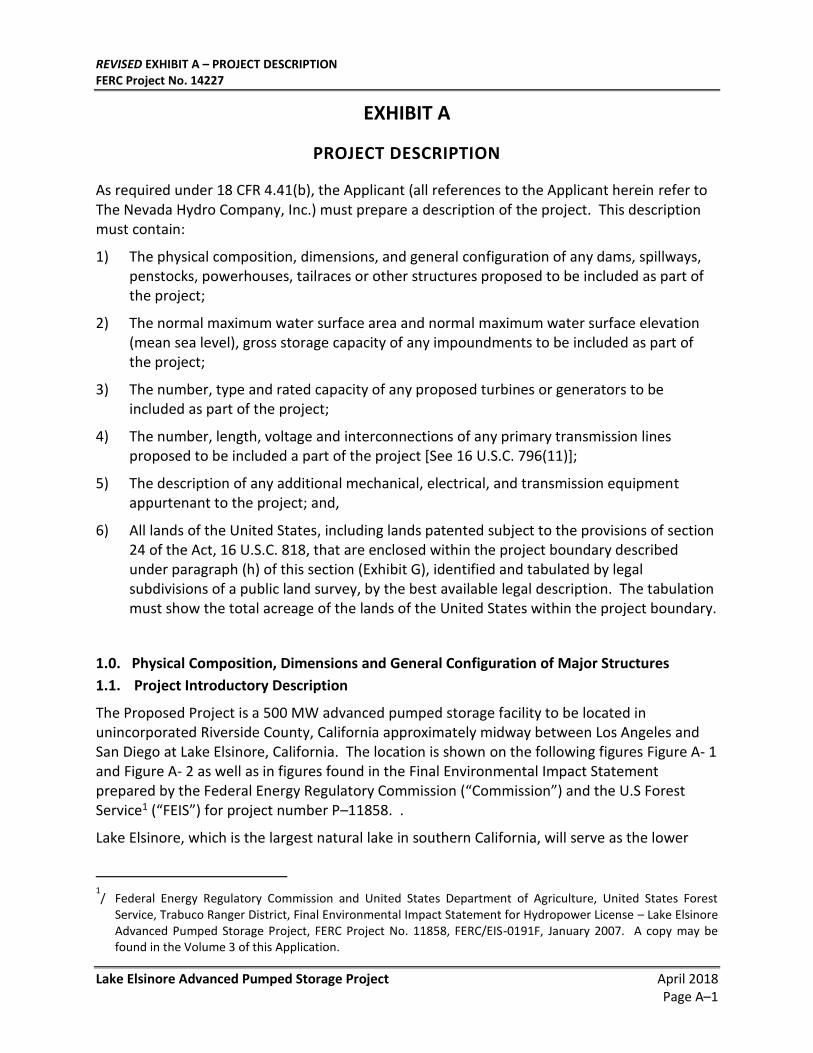
As required under 18 CFR 4.41(b), the Applicant (all references to the Applicant herein refer to The Nevada Hydro Company, Inc.) must prepare a description of the project. This description must contain:
1) The physical composition, dimensions, and general configuration of any dams, spillways, penstocks, powerhouses, tailraces or other structures proposed to be included as part of the project;
2) The normal maximum water surface area and normal maximum water surface elevation (mean sea level), gross storage capacity of any impoundments to be included as part of the project;
3) The number, type and rated capacity of any proposed turbines or generators to be included as part of the project;
4) The number, length, voltage and interconnections of any primary transmission lines proposed to be included a part of the project [See 16 U.S.C. 796(11)];
5) The description of any additional mechanical, electrical, and transmission equipment appurtenant to the project; and,
6) All lands of the United States, including lands patented subject to the provisions of section 24 of the Act, 16 U.S.C. 818, that are enclosed within the project boundary described under paragraph (h) of this section (Exhibit G), identified and tabulated by legal subdivisions of a public land survey, by the best available legal description. The tabulation must show the total acreage of the lands of the United States within the project boundary.
1.0. Physical Composition, Dimensions and General Configuration of Major Structures
1.1. Project Introductory Description
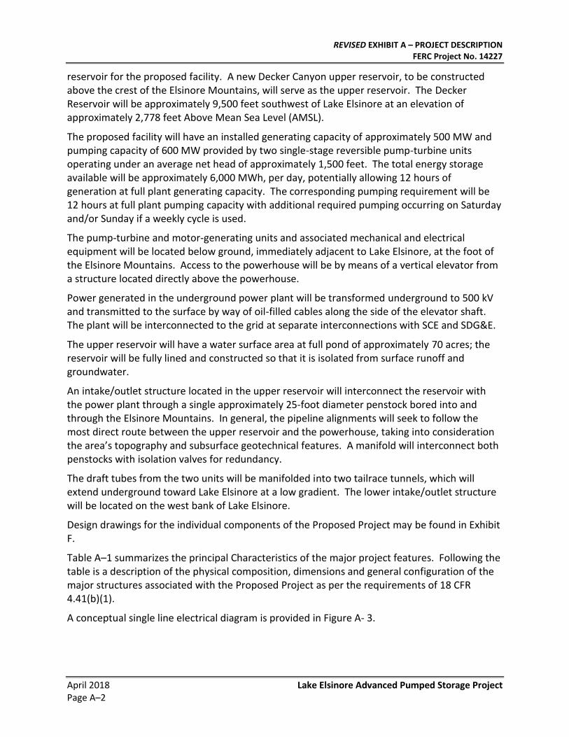
The Proposed Project is a 500 MW advanced pumped storage facility to be located in unincorporated Riverside County, California approximately midway between Los Angeles and San Diego at Lake Elsinore, California. The location is shown on the following figures Figure A- 1 and Figure A- 2 as well as in figures found in the Final Environmental Impact Statement prepared by the Federal Energy Regulatory Commission (“Commission”) and the U.S Forest Service1 (“FEIS”) for project number P–11858. .
Lake Elsinore, which is the largest natural lake in southern California, will serve as the lower
1/ Federal Energy Regulatory Commission and United States Department of Agriculture, United States Forest
Service, Trabuco Ranger District, Final Environmental Impact Statement for Hydropower License – Lake Elsinore Advanced Pumped Storage Project, FERC Project No. 11858, FERC/EIS-0191F, January 2007. A copy may be found in the Volume 3 of this Application.
REVISED EXHIBIT A – PROJECT DESCRIPTION FERC Project No. 14227
April 2018 Lake Elsinore Advanced Pumped Storage Project Page A–2
reservoir for the proposed facility. A new Decker Canyon upper reservoir, to be constructed above the crest of the Elsinore Mountains, will serve as the upper reservoir. The Decker Reservoir will be approximately 9,500 feet southwest of Lake Elsinore at an elevation of approximately 2,778 feet Above Mean Sea Level (AMSL).
The proposed facility will have an installed generating capacity of approximately 500 MW and pumping capacity of 600 MW provided by two single-stage reversible pump-turbine units operating under an average net head of approximately 1,500 feet. The total energy storage available will be approximately 6,000 MWh, per day, potentially allowing 12 hours of generation at full plant generating capacity. The corresponding pumping requirement will be 12 hours at full plant pumping capacity with additional required pumping occurring on Saturday and/or Sunday if a weekly cycle is used.
The pump-turbine and motor-generating units and associated mechanical and electrical equipment will be located below ground, immediately adjacent to Lake Elsinore, at the foot of the Elsinore Mountains. Access to the powerhouse will be by means of a vertical elevator from a structure located directly above the powerhouse.
Power generated in the underground power plant will be transformed underground to 500 kV and transmitted to the surface by way of oil-filled cables along the side of the elevator shaft. The plant will be interconnected to the grid at separate interconnections with SCE and SDG&E.
The upper reservoir will have a water surface area at full pond of approximately 70 acres; the reservoir will be fully lined and constructed so that it is isolated from surface runoff and groundwater.
An intake/outlet structure located in the upper reservoir will interconnect the reservoir with the power plant through a single approximately 25-foot diameter penstock bored into and through the Elsinore Mountains. In general, the pipeline alignments will seek to follow the most direct route between the upper reservoir and the powerhouse, taking into consideration the area’s topography and subsurface geotechnical features. A manifold will interconnect both penstocks with isolation valves for redundancy.
The draft tubes from the two units will be manifolded into two tailrace tunnels, which will extend underground toward Lake Elsinore at a low gradient. The lower intake/outlet structure will be located on the west bank of Lake Elsinore.
Design drawings for the individual components of the Proposed Project may be found in Exhibit F.
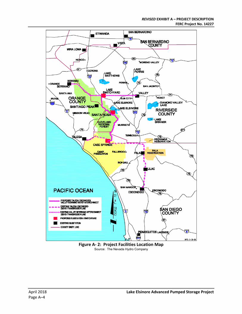
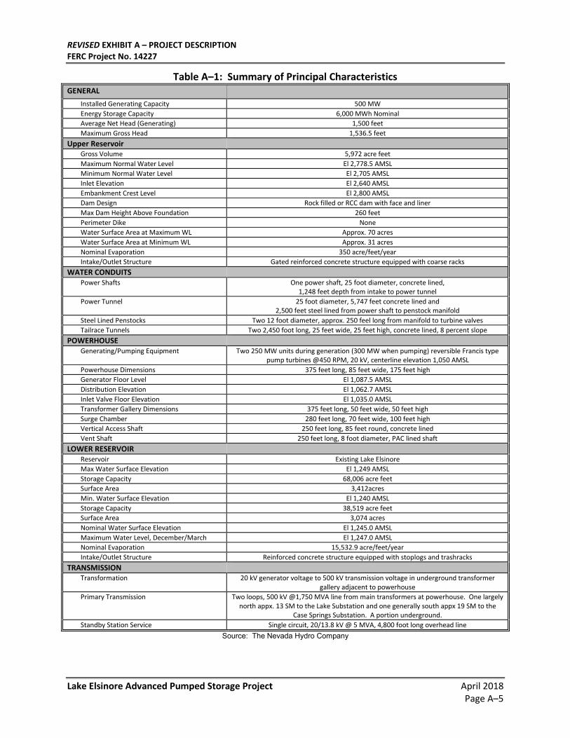
Table A–1 summarizes the principal Characteristics of the major project features. Following the table is a description of the physical composition, dimensions and general configuration of the major structures associated with the Proposed Project as per the requirements of 18 CFR 4.41(b)(1).
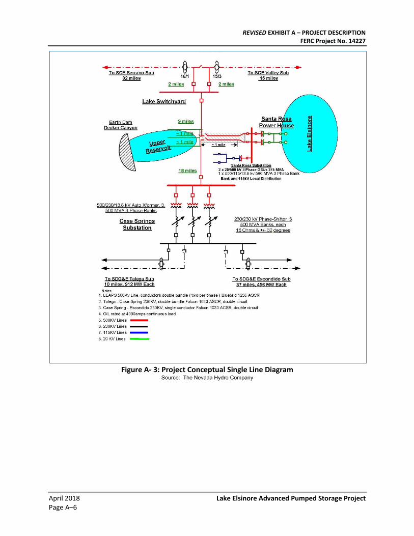
A conceptual single line electrical diagram is provided in Figure A- 3.
REVISED EXHIBIT A – PROJECT DESCRIPTION FERC Project No. 14227
Lake Elsinore Advanced Pumped Storage Project April 2018 Page A–3
Figure A- 1: Regional Location Map
Source: The Nevada Hydro Company
REVISED EXHIBIT A – PROJECT DESCRIPTION FERC Project No. 14227
April 2018 Lake Elsinore Advanced Pumped Storage Project Page A–4
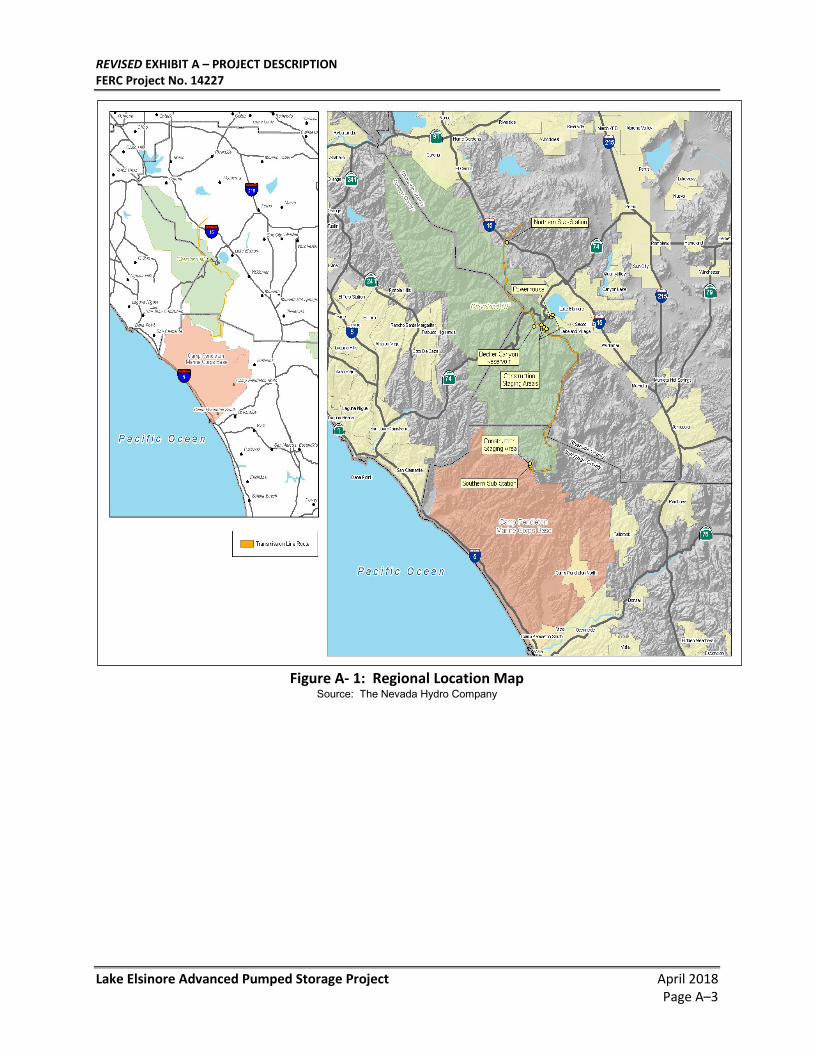
Figure A- 2: Project Facilities Location Map
Source: The Nevada Hydro Company
REVISED EXHIBIT A – PROJECT DESCRIPTION FERC Project No. 14227
Lake Elsinore Advanced Pumped Storage Project April 2018 Page A–5
Table A–1: Summary of Principal Characteristics GENERAL
Installed Generating Capacity 500 MW
Energy Storage Capacity 6,000 MWh Nominal
Average Net Head (Generating) 1,500 feet
Maximum Gross Head 1,536.5 feet
Upper Reservoir Gross Volume 5,972 acre feet
Maximum Normal Water Level El 2,778.5 AMSL
Minimum Normal Water Level El 2,705 AMSL
Inlet Elevation El 2,640 AMSL
Embankment Crest Level El 2,800 AMSL
Dam Design Rock filled or RCC dam with face and liner
Max Dam Height Above Foundation 260 feet
Perimeter Dike None
Water Surface Area at Maximum WL Approx. 70 acres
Water Surface Area at Minimum WL Approx. 31 acres
Nominal Evaporation 350 acre/feet/year
Intake/Outlet Structure Gated reinforced concrete structure equipped with coarse racks
WATER CONDUITS Power Shafts One power shaft, 25 foot diameter, concrete lined,
1,248 feet depth from intake to power tunnel
Power Tunnel 25 foot diameter, 5,747 feet concrete lined and 2,500 feet steel lined from power shaft to penstock manifold
Steel Lined Penstocks Two 12 foot diameter, approx. 250 feel long from manifold to turbine valves
Tailrace Tunnels Two 2,450 foot long, 25 feet wide, 25 feet high, concrete lined, 8 percent slope
POWERHOUSE Generating/Pumping Equipment Two 250 MW units during generation (300 MW when pumping) reversible Francis type
pump turbines @450 RPM, 20 kV, centerline elevation 1,050 AMSL
Powerhouse Dimensions 375 feet long, 85 feet wide, 175 feet high
Generator Floor Level El 1,087.5 AMSL
Distribution Elevation El 1,062.7 AMSL
Inlet Valve Floor Elevation El 1,035.0 AMSL
Transformer Gallery Dimensions 375 feet long, 50 feet wide, 50 feet high
Surge Chamber 280 feet long, 70 feet wide, 100 feet high
Vertical Access Shaft 250 feet long, 85 feet round, concrete lined
Vent Shaft 250 feet long, 8 foot diameter, PAC lined shaft
LOWER RESERVOIR Reservoir Existing Lake Elsinore
Max Water Surface Elevation El 1,249 AMSL
Storage Capacity 68,006 acre feet
Surface Area 3,412acres
Min. Water Surface Elevation El 1,240 AMSL
Storage Capacity 38,519 acre feet
Surface Area 3,074 acres
Nominal Water Surface Elevation El 1,245.0 AMSL
Maximum Water Level, December/March El 1,247.0 AMSL
Nominal Evaporation 15,532.9 acre/feet/year
Intake/Outlet Structure Reinforced concrete structure equipped with stoplogs and trashracks
TRANSMISSION Transformation 20 kV generator voltage to 500 kV transmission voltage in underground transformer
gallery adjacent to powerhouse
Primary Transmission Two loops, 500 kV @1,750 MVA line from main transformers at powerhouse. One largely north appx. 13 SM to the Lake Substation and one generally south appx 19 SM to the
Case Springs Substation. A portion underground.
Standby Station Service Single circuit, 20/13.8 kV @ 5 MVA, 4,800 foot long overhead line
Source: The Nevada Hydro Company
REVISED EXHIBIT A – PROJECT DESCRIPTION FERC Project No. 14227
April 2018 Lake Elsinore Advanced Pumped Storage Project Page A–6
Figure A- 3: Project Conceptual Single Line Diagram
Source: The Nevada Hydro Company
REVISED EXHIBIT A – PROJECT DESCRIPTION FERC Project No. 14227
Lake Elsinore Advanced Pumped Storage Project April 2018 Page A–7
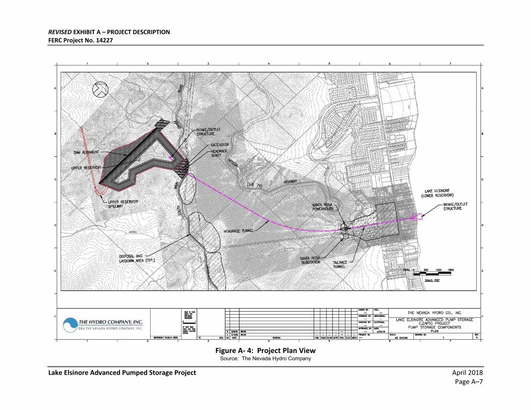
Figure A- 4: Project Plan View
Source: The Nevada Hydro Company
REVISED EXHIBIT A – PROJECT DESCRIPTION FERC Project No. 14227
April 2018 Lake Elsinore Advanced Pumped Storage Project Page A–8
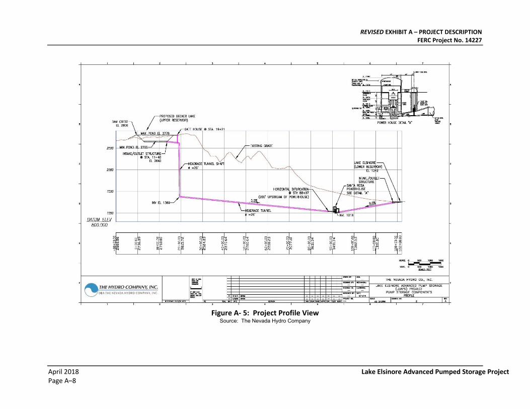
Figure A- 5: Project Profile View
Source: The Nevada Hydro Company
REVISED EXHIBIT A – PROJECT DESCRIPTION FERC Project No. 14227
Lake Elsinore Advanced Pumped Storage Project April 2018 Page A–9
1.2. Upper Reservoir and Associated Structures
1.2.1. Location
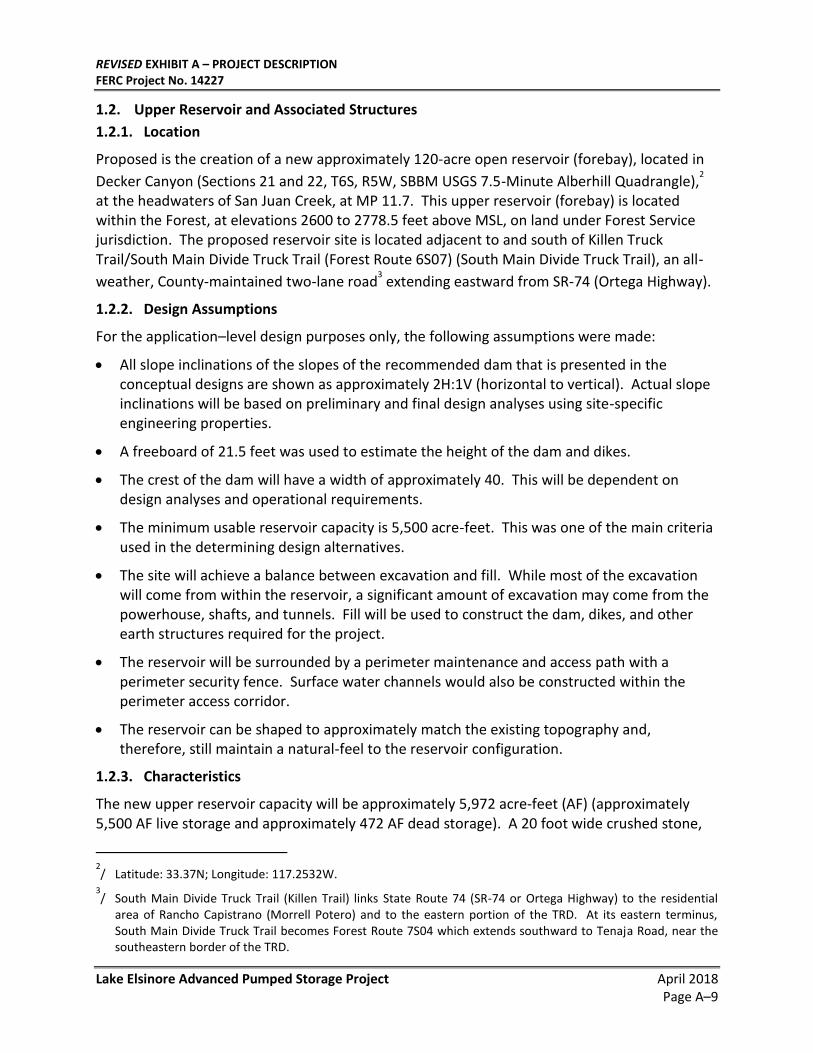
Proposed is the creation of a new approximately 120-acre open reservoir (forebay), located in
Decker Canyon (Sections 21 and 22, T6S, R5W, SBBM USGS 7.5-Minute Alberhill Quadrangle),2
at the headwaters of San Juan Creek, at MP 11.7. This upper reservoir (forebay) is located within the Forest, at elevations 2600 to 2778.5 feet above MSL, on land under Forest Service jurisdiction. The proposed reservoir site is located adjacent to and south of Killen Truck Trail/South Main Divide Truck Trail (Forest Route 6S07) (South Main Divide Truck Trail), an all-
weather, County-maintained two-lane road3 extending eastward from SR-74 (Ortega Highway).
1.2.2. Design Assumptions
For the application–level design purposes only, the following assumptions were made:
• All slope inclinations of the slopes of the recommended dam that is presented in the conceptual designs are shown as approximately 2H:1V (horizontal to vertical). Actual slope inclinations will be based on preliminary and final design analyses using site-specific engineering properties.
• A freeboard of 21.5 feet was used to estimate the height of the dam and dikes.
• The crest of the dam will have a width of approximately 40. This will be dependent on design analyses and operational requirements.
• The minimum usable reservoir capacity is 5,500 acre-feet. This was one of the main criteria used in the determining design alternatives.
• The site will achieve a balance between excavation and fill. While most of the excavation will come from within the reservoir, a significant amount of excavation may come from the powerhouse, shafts, and tunnels. Fill will be used to construct the dam, dikes, and other earth structures required for the project.
• The reservoir will be surrounded by a perimeter maintenance and access path with a perimeter security fence. Surface water channels would also be constructed within the perimeter access corridor.
• The reservoir can be shaped to approximately match the existing topography and, therefore, still maintain a natural-feel to the reservoir configuration.
1.2.3. Characteristics
The new upper reservoir capacity will be approximately 5,972 acre-feet (AF) (approximately 5,500 AF live storage and approximately 472 AF dead storage). A 20 foot wide crushed stone,
2/ Latitude: 33.37N; Longitude: 117.2532W.
3/ South Main Divide Truck Trail (Killen Trail) links State Route 74 (SR-74 or Ortega Highway) to the residential
area of Rancho Capistrano (Morrell Potero) and to the eastern portion of the TRD. At its eastern terminus, South Main Divide Truck Trail becomes Forest Route 7S04 which extends southward to Tenaja Road, near the southeastern border of the TRD.
REVISED EXHIBIT A – PROJECT DESCRIPTION FERC Project No. 14227
April 2018 Lake Elsinore Advanced Pumped Storage Project Page A–10
gravel, or asphalt-access path will be provided around the embankment to allow access for maintenance and inspection. Access will be restricted by signage and an approximately 8 foot high chain-link fence located on the outer side of the crest roadway. Surface water channels will be constructed within the perimeter access corridor.
The sides and bottom of the upper reservoir will be provided with an impermeable dual liner system to minimize water loss and seepage. The liner system will allow for steepened reservoir side slopes by protecting the side slopes from rapid drawdown damage (e.g., sloughing, erosion, and land sliding) and will protect the reservoir floor from erosion and scour.
Double liner systems, with a drainage layer separating a primary (upper) and secondary (lower) liner, are used in applications where leakage at or close to zero is considered paramount. In such systems, because the drainage layer is vented to the atmosphere at 25-foot intervals around the rim at a distance of one foot below the top of slope, virtually no hydraulic head is applied to the secondary liner, thus providing that about 100% of leakage through the primary liner is intercepted and conducted to a collection point for monitoring and disposal.
Fabric-reinforced geomembranes are traditionally used for liners, not only because of their increased strength but also because of their dimensional stability. NSF-61-approved Chlorosulfonated Polyethylene (CSPE, previously known as Hypalon®) is the material of choice for reasons stated above. Specifically, 3-ply, 45-mil 10x10 1000d CSPE geomembrane is recommended for use as the liner for the LEAPS project..The 45-mil thickness is used almost exclusively for liners and floating covers and has performed successfully on countless reservoirs around the world.
Redundant controls will be provided to protect against over-pumping. Three independent systems will be installed to monitor and control the water level in the upper reservoir and to ensure that all units operating in the pumping mode will be tripped before the water level exceeds the final design capacity. These monitoring devices will be coordinated and interlocked in operation to preclude the possibility that failure of a device or a combination of devices and/or any human operating error will allow safe operating levels from being exceeded. For this reason, and since the upper reservoir has no contributory drainage area, no reasonable possibility of exceeding maximum water level will exist.
An intake/outlet structure located in the upper reservoir will interconnect the new upper reservoir with the powerhouse through a single 25 foot diameter nominal conveyance channel and tunnel, with a gated inlet structure. Slide gates will be installed to shut off water flow from the upper reservoir in the event of an emergency or for inspection and repair.
The proposed upper reservoir will be designed for and will accommodate access by firefighting helicopters and other firefighting personnel. Helicopters will be able to utilize reservoir waters to fill suspended “bambi buckets” or other devices for fire suppression. A wind sock or similar device will be installed in a clearly visible location adjacent to the reservoir to assist pilots by indicating wind conditions during firefighting events. In addition, the reservoir’s waters can be pumped from the upper reservoir by mobile water pumping equipment for other fire-response purposes.
Sufficient freeboard will be provided above normal maximum water level to allow for volume
REVISED EXHIBIT A – PROJECT DESCRIPTION FERC Project No. 14227
Lake Elsinore Advanced Pumped Storage Project April 2018 Page A–11
increases from direct rainfall on the pond, interim makeup water storage, and wave run-up due to wind action. In the unlikely event of an emergency, the entire upper reservoir can be discharged into the lower reservoir in approximately 16 hours.
1.2.4. Reservoir Embankment
The proposed upper reservoir design includes: (1) an approximately 260-foot-high main embankment dam located on the southwest side of the reservoir; (2) maximum and minimum pond elevation of approximately 2778.5 feet and 2705 feet above MSL, respectively; (3) a crest elevation of 2800 feet above MSL; and (4) an inlet at elevation of approximately 2640 feet above MSL feet for the intake structure.
The required fill volume of the dam is about 4.4 million cubic yards (CY) of rockfill, with most of the excavation will come from within the area of the reservoir itself. Additional excavation materials may come from the powerhouse, shafts, and penstock tunnels. Excavated and/or imported materials will be used to construct the dam and other earth structures required for the impoundment if required. Materials may be trucked to and from the upper reservoir site along SR-74, via Main Divide Truck Trail.
Embankment material would consist of silty sand and rock materials generated from excavated granitic bedrock and weathered granite. Depending upon the conditions of the bedrock foundation, the dam may be keyed into the foundation rock and the rock foundation may be grouted. All slope inclinations of the dam’s slopes will be approximately 2:1 (horizontal to vertical) but may be constructed flatter to accommodate ground motion criteria currently being evaluated. A freeboard of 21.5 feet was used to estimate the height of the dam. The crest of the dam will have a width of approximately 40 feet. The dam would include a concrete-lined emergency spillway and a low-level outlet.
1.2.5. Intake/Outlet Structure
The intake/outlet structure in the upper reservoir is designed as an inclined structure. A vertical structure was considered, but the required height and the seismic risk for the area led to the conclusion that an inclined structure was required. The structure is shown in Exhibit F. The inclined structure will be supported against the excavated rock face of the reservoir. The reinforced concrete structure will be anchored to rock for stability and to prevent sliding during seismic shaking and to prevent liftoff due to uplift during drawdown of the reservoir.
Between the powerhouse and lower reservoir, the inlet/outfall structure and its associated conduit (tailrace) will be located within an unincorporated County area. At the lakeshore, the inlet/outlet and other associated improvements extending into Lake Elsinore (e.g., intake headwall structure, reinforced dredged channel, and boat dock) will be constructed within the corporate boundaries of the City.
As illustrated in Figure A- 4: Project Plan View and Figure A- 5: Project Profile View, the intake/outlet (tailrace) structure for the lower reservoir will be located near the southwest shoreline of Lake Elsinore. The structure will extend from the portal of the tailrace tunnel to a headwall structure fitted with trashracks at the shoreline. The structure will be designed to provide a maximum discharge velocity of 1.8 feet per second (fps) at the trashracks during
REVISED EXHIBIT A – PROJECT DESCRIPTION FERC Project No. 14227
April 2018 Lake Elsinore Advanced Pumped Storage Project Page A–12
generation and a maximum intake velocity of 1.4 fps at the trashracks during pumping. Stoplogs will be provided at the portal so that the tailrace tunnel can be isolated from Lake Elsinore.
The tailrace structure for the upper reservoir will consist of a gated inlet structure where the water flows into a sloping conduitSlide gates will be installed to shut off water flow from the upper reservoir in the event of an emergency and for inspection and repair of the high-head conduit. The intake/outlet structures will be equipped with trashracks to prevent large debris from entering the conduit system. The structure will be located at sufficient depth below minimum operating level to prevent air entrainment. The intake/outlet structure will be reinforced concrete with automated trashracks and stoplogs and will incorporate fish excluders. Fish excluders can be changed seasonally but not automated.
1.3. Penstocks
Water will be transferred between the upper reservoir and the powerhouse through a single approximately 25 foot diameter, primarily concrete-lined tunnel. The inlet elevation at the proposed upper reservoir will be about 2640 feet above Mean Sea Level (MSL).
A tunnel-boring machine (TBM) or conventional hard-rock mining operation will be used to excavate the headrace tunnels. It is anticipated that the high-head conductor will be excavated into competent granitic bedrock. In general, the pipeline alignments will seek to follow the most direct route between the upper reservoir and the powerhouse, taking into consideration the area’s topography and subsurface geotechnical features.
A vertical tunnel will descend from a location northeast of the upper reservoir. The vertical tunnel will connect to a lower sub-horizontal tunnel that would have a gradient of approximately five percent downward toward the powerhouse. The horizontal tunnel will be unlined or concrete-lined where there is adequate rock cover over the tunnel and steel lined where there is inadequate rock cover. The horizontal tunnel would then split into a steel-lined manifold immediately upstream of the powerhouse, directing the water flows to the turbines in the powerhouse.
A double-seated spherical valve will be provided at the inlet for each pump-turbine spiral case. The valves will be used to isolate the pump-turbine from the penstock for inspection and maintenance and to close in an emergency. Draft tube bulkhead gates will be provided to be used in conjunction with the penstock valves for dewatering the pump-turbine water passages.
1.4. Powerhouse and Associated Shafts and Chambers
1.4.1. Powerhouse
The proposed Santa Rosa Powerhouse site (Section 14, T6S, R5W, SBBM, Lake Elsinore 7.5-Minute USGS Topographic Quadrangle) is approximately located west of the terminus of Santa Rosa Drive, between Ponce Drive and Grape Street, within unincorporated Lakeland Village area of Riverside County. The site is located to the south of SR-74 and west of Grand Avenue.
The proposed underground powerhouse will be situated approximately 3,000 feet from Lake Elsinore, about 330 feet below surface at elevation 1,170 MSL, and with the centerline of the pump/turbine spiral cases at 1,050 MSL. The powerhouse will contain two reversible Francis-
REVISED EXHIBIT A – PROJECT DESCRIPTION FERC Project No. 14227
Lake Elsinore Advanced Pumped Storage Project April 2018 Page A–13
type pump-turbine/motor generators, nominally rated at 300 MW each when pumping. The elevation of the pump/turbines at 192 feet below the surface of the Lake is due to their hydraulic characteristics, so as to provide sufficient suction pressure at the impellers. This suction pressure ensures that the machines will operate without cavitation either in the pump mode or in the turbine mode. The entire water conveyance system (that is the headrace tunnels, the pump/turbine cases, and the tailrace tunnel) is a closed conduit system, so that, when generating, the differential head drop from the upper reservoir (Decker Lake) to the lower reservoir (Lake Elsinore) is the motive energy force and the elevation of the powerhouse, whether above or below the surface of Lake Elsinore does not affect the gross head available to drive the machines.
Each pump/turbine will have adjustable wicket gates controlled by an electronic governor through oil-operated servomotors. Consistent with all Francis-type pump/turbines, the units will operate at relatively constant flow rate while pumping. The pump/turbine runner and wicket gates, as well as other components that may otherwise be susceptible to cavitation, will be of solid stainless steel construction, to prevent cavitation damage.
A service bay will be provided at one end of the powerhouse. Equipment access by overhead crane to the powerhouse will be via a vertical shaft extending from the land surface down to a service bay and laydown area on the generator floor. Personnel will have access via an elevator.
Powerhouse equipment will include an over-head bridge crane supported on high-level beams along the length of the powerhouse. The crane will be sized to handle the heaviest lift during equipment installation and maintenance. The powerhouse cavern housing the pumping/ generating units will be approximately 175 feet long, 250 feet wide, and 160 feet high.
The main powerhouse cavity will contain local operating and control equipment for each unit. The powerhouse roof will be supported by rock bolts or rock anchors with wire mesh and shotcrete for support as needed. The powerhouse will accommodate spherical turbine inlet valves to control flow into the units. The valves will be placed immediately upstream of the spiral case so that they can be handled by the main powerhouse crane.
Galleries for electrical and mechanical services will be provided on the upstream and downstream sides of the powerhouse, respectively. Discharge from the units in the generating mode will pass through the draft tubes into the tailrace tunnel. This tunnel will be D-shaped and concrete-lined.
The power plant’s mechanical systems will be designed to maintain suitable and safe conditions for operators and maintenance personnel. Ventilation air in and out of the powerhouse access tunnel will be provided. The major heat-producing units will be cooled by oil-water and air-water heat-exchange systems. A system of ducting, bulkhead controls, and circulating fans will be installed to ensure equitable distribution of air throughout the facility and prevent the accumulation of carbon monoxide (CO) and other gases. Fire doors, incorporating air locks, will be provided at key locations. Fire prevention systems in the underground plant will be conventional deluge-type for the major items of equipment. Tied to these systems will be a system of isolating dampers and bulkheads connected to the ventilation system for control of
REVISED EXHIBIT A – PROJECT DESCRIPTION FERC Project No. 14227
April 2018 Lake Elsinore Advanced Pumped Storage Project Page A–14
smoke and fumes. In accordance with fire and building code standards, a high-pressure fire system will supply water to fire hose stations located throughout the facility. Unit dewatering will employ high-capacity pumps in pressurized pump pits.
Two 2,000 kW emergency diesel generators will run an air compressor and essential cooling pumps for the powerhouse complex.
Although computer and programmable logic control (PLC) systems improve plant operation by providing greater flexibility in control, alarming, and sequence of events recording, the essential emergency shutdown controls shall remain hardwired. This will guarantee that a safe and orderly shutdown of the plant can be accomplished in an emergency situation during which the computer and PLC systems have failed.
1.4.2. Surge Chamber
The surge chamber will be located on the high pressure side of the powerhouse. The chamber will be approximately 280 feet long, 100 feet high and 70 feet wide. Similar to the transformer gallery, this cavity roof will be supported by rock bolts with wire mesh and PAC, as necessary. The chamber will be vented to the atmosphere via an eight-foot diameter vent shaft, which will also serve as the emergency exit from the underground facilities.
The primary purpose of the surge chamber is to reduce pressure transients in the tailrace tunnel when the units are started and stopped, and to enable satisfactory speed governing of the units. The chamber has been sized to accommodate the draft tube gates and hoists.
1.4.3. Access Shaft
An access shaft will be over the service bay of the powerhouse. The shaft will be a vertical, round, approximately 85 foot diameter shaft, and will be lined.
A service building will be provided over the access shaft portal to house a crane, for storage of maintenance equipment, and for office and other uses.
1.4.4. Vent Shaft
A vent and emergency exit gallery will connect the powerhouse, and surge chamber. An 8-foot diameter PAC-lined shaft will rise approximately 250 feet vertically to ground level to provide ventilation and emergency egress. A surface structure at the entrance to the vent shaft will incorporate protective equipment, including dampers, louvers, and bird screens.
A separate maintenance building will be provided near the vent structure for storing landscaping and other maintenance equipment.
Design drawings for the individual components of the Proposed Project may be found in Exhibit F.
1.5. Lower Reservoir and Associated Structures
1.5.1. Lower Reservoir
Lake Elsinore will serve as the afterbay for the Proposed Project. Lake Elsinore is a relatively
REVISED EXHIBIT A – PROJECT DESCRIPTION FERC Project No. 14227
Lake Elsinore Advanced Pumped Storage Project April 2018 Page A–15
shallow lake with a large surface area. The lake, a naturally occurring sink for the San Jacinto
River watershed, has been significantly modified for water control.4 At the current lake outlet
sill elevation of 1255 feet above MSL, the lake has an average depth of 32 feet and the hypolimnetic water volume and surface area are 89.114 AF extending over 3,606 acres,
respectively.5 Waters within the lake are owned by the Elsinore Valley Municipal Water District
(EVMWD) and the real property within the Ordinary High Water Mark (OHWM) is owned by and located within the corporate boundaries of the City of Lake Elsinore. Public access to the lakeshore is limited to locations along the lakeshore where property is publicly owned.
Lake Elsinore is located within numerous sections of the Lake Elsinore and Alberhill 7.5-Minute USGS Topographic Quadrangles. A number of maps and aerial photographs may be seen in Figure G–1 (Project Route Facility Map) and Figure G–2 (TE 230 Route Map) of Exhibit G.
To prevent a large difference in lake water elevation, a major management project was undertaken by the Santa Ana Watershed Project Authority, supervised by the Santa Ana Watershed Project, and built by the United States Army Corps of Engineers. Beginning in about 1988, a 17,800-foot rolled earth-filled levee was constructed to separate the main basin from the larger approximately 6,000-acre floodplain comprising the lake’s historic boundaries. A 1,600-foot overflow weir was constructed from the end of the levee across the San Jacinto River channel to divert excess flood waters into the back basin for storage. An outlet channel, with a sill elevation of approximately 1255 feet AMSL, was subsequently constructed to drain excessive water during flood events. During normal conditions, water is stored in the north part (main basin) of the lake. The south part (back basin) of the lake provides additional storage capacity for 50-year and 100-year storm events. The 100-year flood elevation is maintained at 1263.3 feet AMSL.
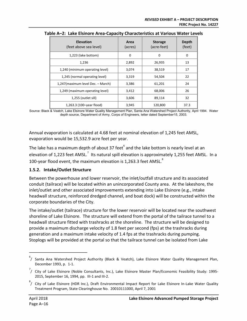
The lake, which has a generally rectangular shape with its major axis aligned northwest to southeast, is comprised of a main basin and a 356-acre wetland and flood control facility, referred to as the back basin, situated southeast of the main basin. A 48-inch gated conduit in the levee allows water to pass between the lake and the wetland area. As illustrated in Table A–2, at that elevation, the storage capacity of the lake and back basin is approximately 150,000 acre-feet (AF).
Under normal operating conditions, a two-mile inlet channel routes water from the San Jacinto River into the back basin which helps maintain the lake level at a minimum operating elevation of 1240 feet AMSL. During storm events, water is routed through a weir into the floodplain located at the southeastern part of the lake.
4/ Lichvar, Robert, Gustina, Gregory, Ericsson, Michael, Planning Level Delineation and Geospatial
Characterization of Aquatic Resources for San Jacinto and Portions of Santa Margarita Watershed, Riverside County, California, United States Army Corps of Engineers, March 2003, p. 28.
5/ Lake Elsinore and San Jacinto Watershed Authority (Montgomery Watson Harza), Final Program Environmental
Impact Report – Lake Elsinore Stabilization and Enhancement Project, SCH No. 2001071042, September 2005, p. 5-19.
REVISED EXHIBIT A – PROJECT DESCRIPTION FERC Project No. 14227
April 2018 Lake Elsinore Advanced Pumped Storage Project Page A–16
Table A–2: Lake Elsinore Area-Capacity Characteristics at Various Water Levels
Elevation (feet above sea level)
Area (acres)
Storage (acre-feet)
Depth (feet)
1,223 (lake bottom) 0 0 0
1,236 2,892 26,935 13
1,240 (minimum operating level) 3,074 38,519 17
1,245 (normal operating level) 3,319 54,504 22
1,247(maximum level Dec. – March) 3,386 61,201 24
1,249 (maximum operating level) 3,412 68,006 26
1,255 (outlet sill) 3,606 89,114 32
1,263.3 (100–year flood) 3,945 120,800 37.3
Source: Black & Veatch, Lake Elsinore Water Quality Management Plan, Santa Ana Watershed Project Authority, April 1994. Water depth source, Department of Army, Corps of Engineers, letter dated September15, 2003.
Annual evaporation is calculated at 4.68 feet at nominal elevation of 1,245 feet AMSL, evaporation would be 15,532.9 acre feet per year.
The lake has a maximum depth of about 37 feet6 and the lake bottom is nearly level at an
elevation of 1,223 feet AMSL.7 Its natural spill elevation is approximately 1,255 feet AMSL. In a
100-year flood event, the maximum elevation is 1,263.3 feet AMSL.8
1.5.2. Intake/Outlet Structure
Between the powerhouse and lower reservoir, the inlet/outfall structure and its associated conduit (tailrace) will be located within an unincorporated County area. At the lakeshore, the inlet/outlet and other associated improvements extending into Lake Elsinore (e.g., intake headwall structure, reinforced dredged channel, and boat dock) will be constructed within the corporate boundaries of the City.
The intake/outlet (tailrace) structure for the lower reservoir will be located near the southwest shoreline of Lake Elsinore. The structure will extend from the portal of the tailrace tunnel to a headwall structure fitted with trashracks at the shoreline. The structure will be designed to provide a maximum discharge velocity of 1.8 feet per second (fps) at the trashracks during generation and a maximum intake velocity of 1.4 fps at the trashracks during pumping. Stoplogs will be provided at the portal so that the tailrace tunnel can be isolated from Lake
6/ Santa Ana Watershed Project Authority (Black & Veatch), Lake Elsinore Water Quality Management Plan,
December 1993, p. 1-1. 7/ City of Lake Elsinore (Noble Consultants, Inc.), Lake Elsinore Master Plan/Economic Feasibility Study: 1995-
2015, September 16, 1994, pp. III-1 and III-2. 8/ City of Lake Elsinore (HDR Inc.), Draft Environmental Impact Report for Lake Elsinore In-Lake Water Quality
Treatment Program, State Clearinghouse No. 20010111000, April 7, 2001
REVISED EXHIBIT A – PROJECT DESCRIPTION FERC Project No. 14227
Lake Elsinore Advanced Pumped Storage Project April 2018 Page A–17
Elsinore.
A rip-rap lined, reinforced dredged channel at the inlet/outlet (tailrace) structure will be installed to reduce velocities, provide a natural silt trap, and shape a velocity profile into the intake screens, structure, and gates. Following construction, the cofferdam will be removed. A paved maintenance road would provide shoreline access and a boat dock installed to allow for lake access during facility maintenance. The area will be equipped with security cables, warning signs, warning buoys, security cameras, and navigational warning lights.
2.0. Reservoir Characteristics
2.1. Upper Reservoir
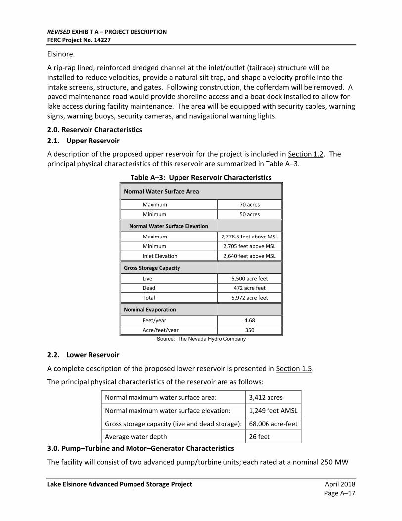
A description of the proposed upper reservoir for the project is included in Section 1.2. The principal physical characteristics of this reservoir are summarized in Table A–3.
Table A–3: Upper Reservoir Characteristics
Normal Water Surface Area
Maximum 70 acres
Minimum 50 acres
Normal Water Surface Elevation
Maximum 2,778.5 feet above MSL
Minimum 2,705 feet above MSL
Inlet Elevation 2,640 feet above MSL
Gross Storage Capacity
Live 5,500 acre feet
Dead 472 acre feet
Total 5,972 acre feet
Nominal Evaporation
Feet/year 4.68
Acre/feet/year 350
Source: The Nevada Hydro Company
2.2. Lower Reservoir
A complete description of the proposed lower reservoir is presented in Section 1.5.
The principal physical characteristics of the reservoir are as follows:
Normal maximum water surface area: 3,412 acres
Normal maximum water surface elevation: 1,249 feet AMSL
Gross storage capacity (live and dead storage): 68,006 acre-feet
Average water depth 26 feet
3.0. Pump–Turbine and Motor–Generator Characteristics
The facility will consist of two advanced pump/turbine units; each rated at a nominal 250 MW
REVISED EXHIBIT A – PROJECT DESCRIPTION FERC Project No. 14227
April 2018 Lake Elsinore Advanced Pumped Storage Project Page A–18
generating capacity and 300 MW pumping capacity supplied by Voith Hydropower, or equivalent. The pump/turbine will be a vertical shaft single-stage one-speed, 450 RPM, Francis-type reversible machine, and will directly connect to a suitably sized generator/motor at 20 kV. The pump/turbine will be equipped with a 90 inch spherical valve, located at the inlet of the machine when turbining, for shut-off and for pump starting. All necessary valve controls will be included. A digital/hydraulic governor of modern design will control the pump/turbine, and the generator/motor will be fitted with Static excitation. A Static Frequency Converter (SFC) will be employed to start the units as pumps. The generator/motor will be connected through circuit breakers to a main step transformer, which will step up the voltage to that of the transmission line. All components of the system will be equipped with control and protection devices which are the most modern in design.
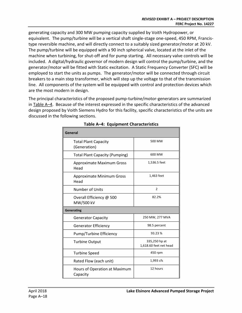
The principal characteristics of the proposed pump-turbine/motor-generators are summarized in Table A–4. Because of the interest expressed in the specific characteristics of the advanced design proposed by Voith Siemens Hydro for this facility, specific characteristics of the units are discussed in the following sections.
Table A–4: Equipment Characteristics
General
Total Plant Capacity (Generation)
500 MW
Total Plant Capacity (Pumping) 600 MW
Approximate Maximum Gross Head
1,536.5 feet
Approximate Minimum Gross Head
1,463 feet
Number of Units 2
Overall Efficiency @ 500 MW/500 kV
82.2%
Generating
Generator Capacity 250 MW, 277 MVA
Generator Efficiency 98.5 percent
Pump/Turbine Efficiency 93.23 %
Turbine Output 335,250 hp at 1,618.60 feet net head
Turbine Speed 450 rpm
Rated Flow (each unit) 1,993 cfs
Hours of Operation at Maximum Capacity
12 hours
REVISED EXHIBIT A – PROJECT DESCRIPTION FERC Project No. 14227
Lake Elsinore Advanced Pumped Storage Project April 2018 Page A–19
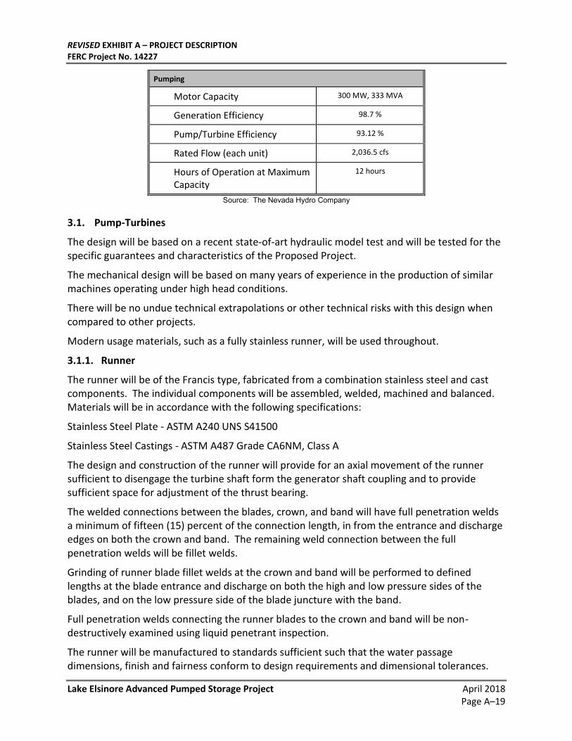
Pumping
Motor Capacity 300 MW, 333 MVA
Generation Efficiency 98.7 %
Pump/Turbine Efficiency 93.12 %
Rated Flow (each unit) 2,036.5 cfs
Hours of Operation at Maximum Capacity
12 hours
Source: The Nevada Hydro Company
3.1. Pump-Turbines
The design will be based on a recent state-of-art hydraulic model test and will be tested for the specific guarantees and characteristics of the Proposed Project.
The mechanical design will be based on many years of experience in the production of similar machines operating under high head conditions.
There will be no undue technical extrapolations or other technical risks with this design when compared to other projects.
Modern usage materials, such as a fully stainless runner, will be used throughout.
3.1.1. Runner
The runner will be of the Francis type, fabricated from a combination stainless steel and cast components. The individual components will be assembled, welded, machined and balanced. Materials will be in accordance with the following specifications:
Stainless Steel Plate - ASTM A240 UNS S41500
Stainless Steel Castings - ASTM A487 Grade CA6NM, Class A
The design and construction of the runner will provide for an axial movement of the runner sufficient to disengage the turbine shaft form the generator shaft coupling and to provide sufficient space for adjustment of the thrust bearing.
The welded connections between the blades, crown, and band will have full penetration welds a minimum of fifteen (15) percent of the connection length, in from the entrance and discharge edges on both the crown and band. The remaining weld connection between the full penetration welds will be fillet welds.
Grinding of runner blade fillet welds at the crown and band will be performed to defined lengths at the blade entrance and discharge on both the high and low pressure sides of the blades, and on the low pressure side of the blade juncture with the band.
Full penetration welds connecting the runner blades to the crown and band will be non-destructively examined using liquid penetrant inspection.
The runner will be manufactured to standards sufficient such that the water passage dimensions, finish and fairness conform to design requirements and dimensional tolerances.
REVISED EXHIBIT A – PROJECT DESCRIPTION FERC Project No. 14227
April 2018 Lake Elsinore Advanced Pumped Storage Project Page A–20
3.1.2. Turbine Shaft
The turbine shaft will be designed to operate safely without excessive vibration and at maximum torque without exceeding the allowable stresses. The solid shaft will be of forged steel and be equipped with a bearing collar, external flanges on both ends and a central inspection bore.
The shaft will be provided with an integral support for mounting of the shaft seal sliding ring or a suitable fitted area for mounting of the sliding ring support.
Steel bolts and nuts will be provided to couple the turbine shaft to the generator shaft. The bolts will be designed to transmit the shaft torque. A steel template will be provided for drilling the coupling bolt holes. The pump-turbine runner shaft and the motor generator shafts will be coupled and have runout checks per ANSI/IEEE Standard 810 during the field assembly.
A fabricated steel shaft guard will attach to the shaft and generator flange for covering the generator coupling bolts and nuts.
3.1.3. Spiral Case/Stay Ring
The spiral case will be fabricated of carbon steel plate in sections prepared for field welding to one another and to the stay ring assembly. All field joints will have the edges suitably prepared for field welding. Where plates for the spiral case change thickness, the transition will be made on the outside of the plates at the reducing section, maintaining a flush joint on the inside of the case.
Drain connections of carbon steel will be used for the de-watering of the spiral case. Stainless steel grating will be used over the opening inside the spiral case.
A set of stainless steel piezometer taps will be welded to the inlet pipe for water flow and pressure measurement.
The stay ring will be fabricated from either medium strength steel plate or castings or cast, with the top/bottom deck plates connected by stay vanes. Machined flanges integral with the stay ring will be provided for bolted connection of the stay ring to the head cover and to the bottom ring. A sufficient number of pads for the placement of jacks and fasteners for hold down during installation and concreting will be provided.
The spiral case and inlet pipe will be fabricated of medium strength steel plate and the spiral case will be factory welded to the stay ring assembly as far as practicable. The spiral case/stay ring will be delivered in one piece if the shipping dimensions permit this. If not, the equipment will be divided into as few sub-assemblies as necessary.
Pressure test equipment for pressure testing at site will be utilized. An elastomeric material will be installed on the top portion of the spiral case prior to embedment.
There will be a sufficient number of pads for placement of jacks and fasteners for hold down during installation.
3.1.4. Draft Tube
The upper draft tube conical section will be a welded steel component that provides for a
REVISED EXHIBIT A – PROJECT DESCRIPTION FERC Project No. 14227
Lake Elsinore Advanced Pumped Storage Project April 2018 Page A–21
smooth hydraulic transition between the discharge/bottom ring and the draft tube. This component will be welded to the discharge ring and will be designed rigidly to withstand pressure variations or pulsations under operation. The outside surface of the conical section will be provided with sufficient ribs for reinforcement and sufficient welded anchors for concrete embedment.
The draft tube liner will be a multi-piece welded steel component and will be welded to the upper draft tube conical section. To facilitate transport restrictions, the liner will be sectionalized for field welding. The exterior surfaces of the liner will be reinforced with sufficient ribs or structural steel shapes and provided with adequate means for securely anchoring the liner to the surrounding concrete substructure. The draft tube liner will be provided with adequate brackets or pads for the application of leveling jacks and hold-down rods during field erection.
A welded steel door located in the draft tube coned will provide access to the downstream portions of the turbine. The inside face of the door will be flush with the inside face of the cone. A test cock will be provided to determine whether the water level in the draft tube is below the sill of the door. All draft tube parts, such as brackets and pads, embedded in first state concrete will be provided with a sufficient number of welded anchors to establish a firm grip to the surrounding concrete substructure.
3.1.5. Pit Liner
The turbine pit liner will be carbon steel plate and shipped in sections for field welding. Recesses for mounting servomotor cylinders and transmitting the reactions of the servos with the aid of foundation plates will be provided.
3.1.6. Wicket Gates
The wicket gates will be high strength chrome-nickel (13% Chrome, 4% nickel) stainless steel castings with integral stems and trunnions.
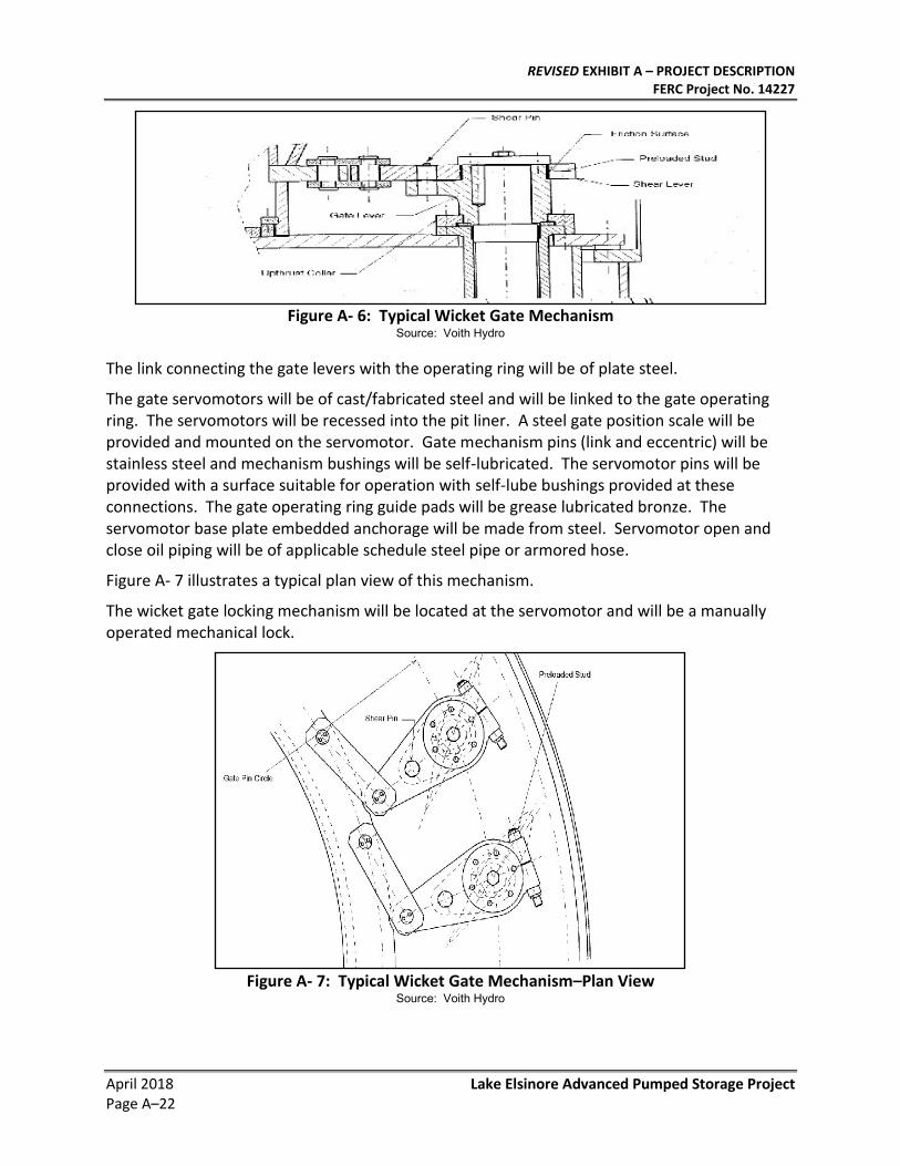
3.1.7. Wicket Gate Mechanism with Two Gate Servomotors
The wicket gate mechanism will consist of the gate levers, gate links, operating ring and two gate servomotors attached to the pit liner foundation. Figure A- 6 illustrates a typical vertical cross section view.
The gate lever, made of carbon steel, will be firmly attached to the gate stem. It will consist of the inner lever and outer lever, with transferring the lever torque through a shear pin. A gate restraining mechanism (friction brake) will prevent the gate from swinging freely when a shear pin is broken.
REVISED EXHIBIT A – PROJECT DESCRIPTION FERC Project No. 14227
April 2018 Lake Elsinore Advanced Pumped Storage Project Page A–22
Figure A- 6: Typical Wicket Gate Mechanism
Source: Voith Hydro
The link connecting the gate levers with the operating ring will be of plate steel.
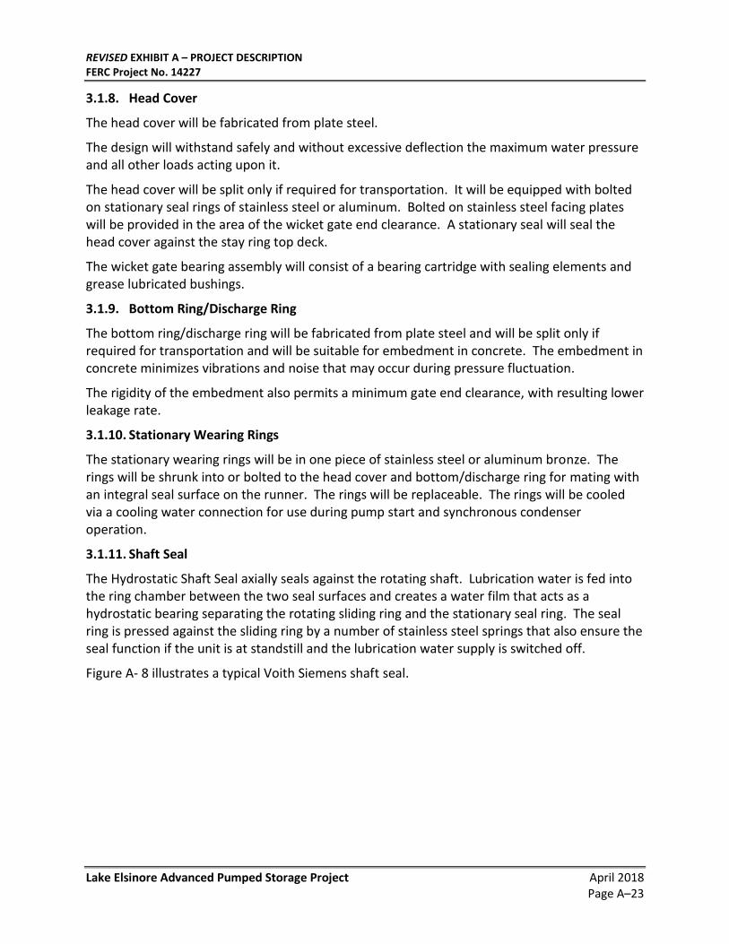
The gate servomotors will be of cast/fabricated steel and will be linked to the gate operating ring. The servomotors will be recessed into the pit liner. A steel gate position scale will be provided and mounted on the servomotor. Gate mechanism pins (link and eccentric) will be stainless steel and mechanism bushings will be self-lubricated. The servomotor pins will be provided with a surface suitable for operation with self-lube bushings provided at these connections. The gate operating ring guide pads will be grease lubricated bronze. The servomotor base plate embedded anchorage will be made from steel. Servomotor open and close oil piping will be of applicable schedule steel pipe or armored hose.
Figure A- 7 illustrates a typical plan view of this mechanism.
The wicket gate locking mechanism will be located at the servomotor and will be a manually operated mechanical lock.
Figure A- 7: Typical Wicket Gate Mechanism–Plan View
Source: Voith Hydro
REVISED EXHIBIT A – PROJECT DESCRIPTION FERC Project No. 14227
Lake Elsinore Advanced Pumped Storage Project April 2018 Page A–23
3.1.8. Head Cover
The head cover will be fabricated from plate steel.
The design will withstand safely and without excessive deflection the maximum water pressure and all other loads acting upon it.
The head cover will be split only if required for transportation. It will be equipped with bolted on stationary seal rings of stainless steel or aluminum. Bolted on stainless steel facing plates will be provided in the area of the wicket gate end clearance. A stationary seal will seal the head cover against the stay ring top deck.
The wicket gate bearing assembly will consist of a bearing cartridge with sealing elements and grease lubricated bushings.
3.1.9. Bottom Ring/Discharge Ring
The bottom ring/discharge ring will be fabricated from plate steel and will be split only if required for transportation and will be suitable for embedment in concrete. The embedment in concrete minimizes vibrations and noise that may occur during pressure fluctuation.
The rigidity of the embedment also permits a minimum gate end clearance, with resulting lower leakage rate.
3.1.10. Stationary Wearing Rings
The stationary wearing rings will be in one piece of stainless steel or aluminum bronze. The rings will be shrunk into or bolted to the head cover and bottom/discharge ring for mating with an integral seal surface on the runner. The rings will be replaceable. The rings will be cooled via a cooling water connection for use during pump start and synchronous condenser operation.
3.1.11. Shaft Seal
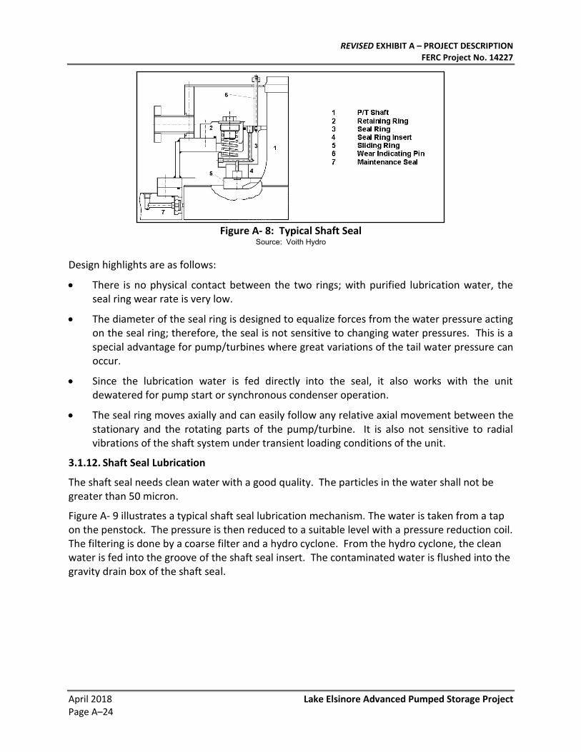
The Hydrostatic Shaft Seal axially seals against the rotating shaft. Lubrication water is fed into the ring chamber between the two seal surfaces and creates a water film that acts as a hydrostatic bearing separating the rotating sliding ring and the stationary seal ring. The seal ring is pressed against the sliding ring by a number of stainless steel springs that also ensure the seal function if the unit is at standstill and the lubrication water supply is switched off.
Figure A- 8 illustrates a typical Voith Siemens shaft seal.
REVISED EXHIBIT A – PROJECT DESCRIPTION FERC Project No. 14227
April 2018 Lake Elsinore Advanced Pumped Storage Project Page A–24
Figure A- 8: Typical Shaft Seal
Source: Voith Hydro
Design highlights are as follows:
• There is no physical contact between the two rings; with purified lubrication water, the seal ring wear rate is very low.
• The diameter of the seal ring is designed to equalize forces from the water pressure acting on the seal ring; therefore, the seal is not sensitive to changing water pressures. This is a special advantage for pump/turbines where great variations of the tail water pressure can occur.
• Since the lubrication water is fed directly into the seal, it also works with the unit dewatered for pump start or synchronous condenser operation.
• The seal ring moves axially and can easily follow any relative axial movement between the stationary and the rotating parts of the pump/turbine. It is also not sensitive to radial vibrations of the shaft system under transient loading conditions of the unit.
3.1.12. Shaft Seal Lubrication
The shaft seal needs clean water with a good quality. The particles in the water shall not be greater than 50 micron.
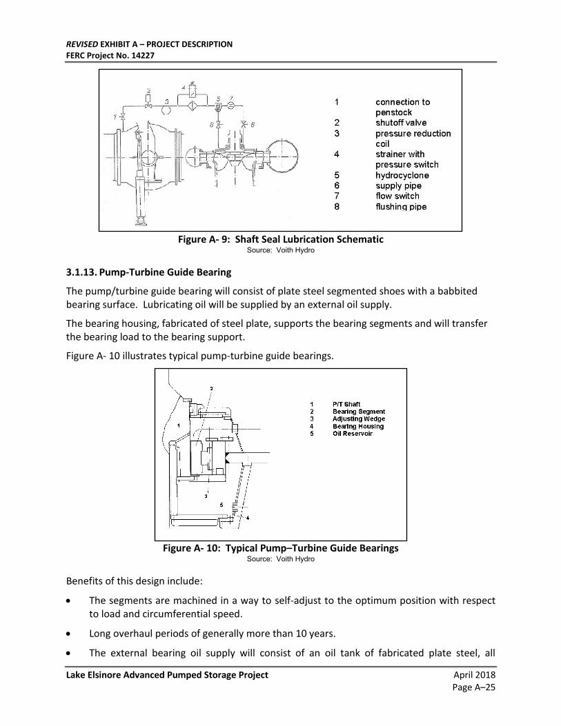
Figure A- 9 illustrates a typical shaft seal lubrication mechanism. The water is taken from a tap on the penstock. The pressure is then reduced to a suitable level with a pressure reduction coil. The filtering is done by a coarse filter and a hydro cyclone. From the hydro cyclone, the clean water is fed into the groove of the shaft seal insert. The contaminated water is flushed into the gravity drain box of the shaft seal.
REVISED EXHIBIT A – PROJECT DESCRIPTION FERC Project No. 14227
Lake Elsinore Advanced Pumped Storage Project April 2018 Page A–25
Figure A- 9: Shaft Seal Lubrication Schematic
Source: Voith Hydro
3.1.13. Pump-Turbine Guide Bearing
The pump/turbine guide bearing will consist of plate steel segmented shoes with a babbited bearing surface. Lubricating oil will be supplied by an external oil supply.
The bearing housing, fabricated of steel plate, supports the bearing segments and will transfer the bearing load to the bearing support.
Figure A- 10 illustrates typical pump-turbine guide bearings.
Figure A- 10: Typical Pump–Turbine Guide Bearings
Source: Voith Hydro
Benefits of this design include:
• The segments are machined in a way to self-adjust to the optimum position with respect to load and circumferential speed.
• Long overhaul periods of generally more than 10 years.
• The external bearing oil supply will consist of an oil tank of fabricated plate steel, all
REVISED EXHIBIT A – PROJECT DESCRIPTION FERC Project No. 14227
April 2018 Lake Elsinore Advanced Pumped Storage Project Page A–26
necessary piping, pumps, filters, access cover, and oil level indicator. Two oil coolers with stainless steel tubing including valves, seals and supports will also be supplied.
The following monitoring instruments will be included:
• 2 mercury spring-type remote thermometers with contacts and indicating instruments for the bearing;
• 2 resistance-type thermometers for remote indication of bearing temperature;
• 1 thermostat for the external oil tank;
• 4 thermometers for local indication;
• 2 precision manometers in the pump pressure side pipe;
• 2 pressure switches with contacts, arranged in the pump pressure side piping;
• 1 flow indicator with contacts in the oil admission pipes;
• 1 level monitoring device with contacts in the oil pan of the guide bearing; and
• 1 level monitoring device with contacts in the external oil tank.
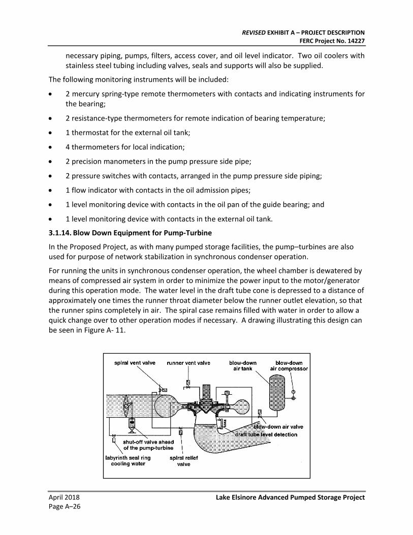
3.1.14. Blow Down Equipment for Pump-Turbine
In the Proposed Project, as with many pumped storage facilities, the pump–turbines are also used for purpose of network stabilization in synchronous condenser operation.
For running the units in synchronous condenser operation, the wheel chamber is dewatered by means of compressed air system in order to minimize the power input to the motor/generator during this operation mode. The water level in the draft tube cone is depressed to a distance of approximately one times the runner throat diameter below the runner outlet elevation, so that the runner spins completely in air. The spiral case remains filled with water in order to allow a quick change over to other operation modes if necessary. A drawing illustrating this design can be seen in Figure A- 11.
REVISED EXHIBIT A – PROJECT DESCRIPTION FERC Project No. 14227
Lake Elsinore Advanced Pumped Storage Project April 2018 Page A–27
Figure A- 11: Blow Down Equipment Source: Voith Hydro
A steel tailwater level detection system will be provided to control the tailwater level depression system. Rise and fall of water level in the draft tube will be detected and that information used to supply, supplement and stop compressed air to the draft tube at condenser operation and at start as a pump, to release compressed air in the draft tube through the exhaust pipe, and to control the pump-turbines.
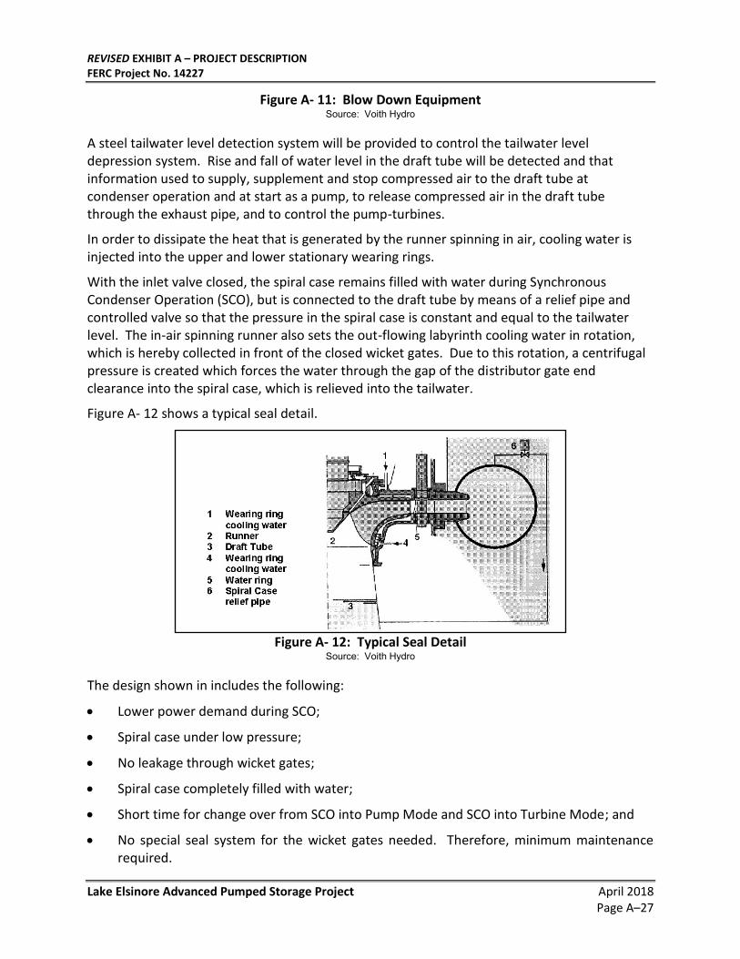
In order to dissipate the heat that is generated by the runner spinning in air, cooling water is injected into the upper and lower stationary wearing rings.
With the inlet valve closed, the spiral case remains filled with water during Synchronous Condenser Operation (SCO), but is connected to the draft tube by means of a relief pipe and controlled valve so that the pressure in the spiral case is constant and equal to the tailwater level. The in-air spinning runner also sets the out-flowing labyrinth cooling water in rotation, which is hereby collected in front of the closed wicket gates. Due to this rotation, a centrifugal pressure is created which forces the water through the gap of the distributor gate end clearance into the spiral case, which is relieved into the tailwater.
Figure A- 12 shows a typical seal detail.
Figure A- 12: Typical Seal Detail
Source: Voith Hydro
The design shown in includes the following:
• Lower power demand during SCO;
• Spiral case under low pressure;
• No leakage through wicket gates;
• Spiral case completely filled with water;
• Short time for change over from SCO into Pump Mode and SCO into Turbine Mode; and
• No special seal system for the wicket gates needed. Therefore, minimum maintenance required.
REVISED EXHIBIT A – PROJECT DESCRIPTION FERC Project No. 14227
April 2018 Lake Elsinore Advanced Pumped Storage Project Page A–28
3.1.15. Covers, Walkways and Railings
Walkways constructed of aluminum bar grate, railings, covers and protective devices will be included in the turbine pit design to provide safe access.
3.1.16. Monorail
The turbine pit will also include an electric monorail hoist.
3.1.17. Inspection and/or Installation Platform in the Draft Tube
The draft tube inspection platform will have an aluminum frame.
3.1.18. Piping
The following piping and related systems will be included:
• The cooling water flow meter will be installed immediately outside the generator pit on each unit;
• A system to supply clean water to the Pump-Turbine (P/T) shaft seal including the filters and related piping outside the P/T pit;
• Governor oil piping connecting all components of the Governor System supply (i.e. servomotors, actuator panel, HPU and pressure tank);
• Spherical valve oil piping connecting spherical valve servomotor, HPU and pressure tank;
• Governor compressed air piping connecting compressors, air receiver and governor pressure tank;
• Spherical valve compressed air piping connecting compressors, air receiver and spherical valve pressure tank; and
• Spherical valve by-pass valves and piping, seal water piping and spiral case relief piping and vent piping.
3.1.19. Flow Measurement System
A modern system for flow measurements through the pump/turbine will be provided.
Each pump-turbine will have adjustable wicket gates controlled by an electronic governor through oil-operated servomotors. Consistent with all Francis pump-turbines, the units will operate at a more or less constant flow rate-while pumping.
The pump-turbine runner and wicket gates will be made of solid stainless-steel construction to prevent cavitation damage: Other components that may be susceptible to cavitation will also be made from stainless steel or will be stainless steel clad.
The pump-turbine distributor will be set approximately 192 feet below minimum tailwater level, to minimize cavitation damage.
3.2. Motor-Generators
Two motor generators will be vertical synchronous machines directly connected to the pump turbines. The units are air cooled with air–to–water heat exchangers.
REVISED EXHIBIT A – PROJECT DESCRIPTION FERC Project No. 14227
Lake Elsinore Advanced Pumped Storage Project April 2018 Page A–29
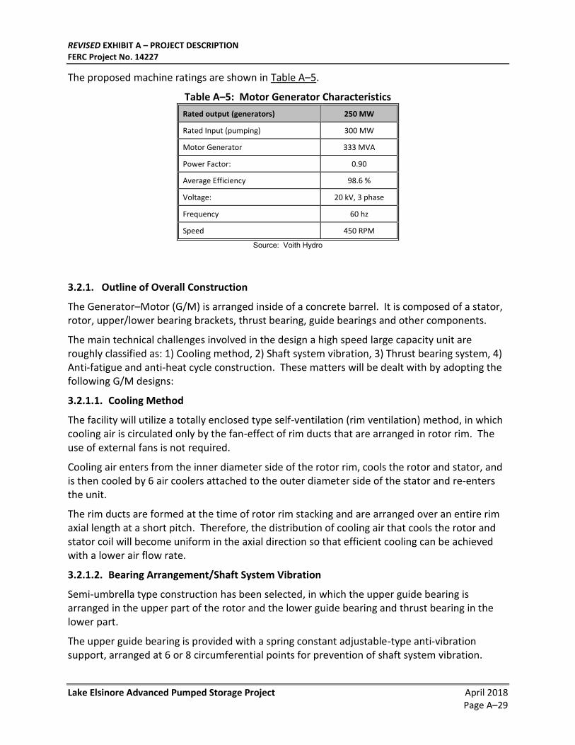
The proposed machine ratings are shown in Table A–5.
Table A–5: Motor Generator Characteristics
Rated output (generators) 250 MW
Rated Input (pumping) 300 MW
Motor Generator 333 MVA
Power Factor: 0.90
Average Efficiency 98.6 %
Voltage: 20 kV, 3 phase
Frequency 60 hz
Speed 450 RPM
Source: Voith Hydro
3.2.1. Outline of Overall Construction
The Generator–Motor (G/M) is arranged inside of a concrete barrel. It is composed of a stator, rotor, upper/lower bearing brackets, thrust bearing, guide bearings and other components.
The main technical challenges involved in the design a high speed large capacity unit are roughly classified as: 1) Cooling method, 2) Shaft system vibration, 3) Thrust bearing system, 4) Anti-fatigue and anti-heat cycle construction. These matters will be dealt with by adopting the following G/M designs:
3.2.1.1. Cooling Method
The facility will utilize a totally enclosed type self-ventilation (rim ventilation) method, in which cooling air is circulated only by the fan-effect of rim ducts that are arranged in rotor rim. The use of external fans is not required.
Cooling air enters from the inner diameter side of the rotor rim, cools the rotor and stator, and is then cooled by 6 air coolers attached to the outer diameter side of the stator and re-enters the unit.
The rim ducts are formed at the time of rotor rim stacking and are arranged over an entire rim axial length at a short pitch. Therefore, the distribution of cooling air that cools the rotor and stator coil will become uniform in the axial direction so that efficient cooling can be achieved with a lower air flow rate.
3.2.1.2. Bearing Arrangement/Shaft System Vibration
Semi-umbrella type construction has been selected, in which the upper guide bearing is arranged in the upper part of the rotor and the lower guide bearing and thrust bearing in the lower part.
The upper guide bearing is provided with a spring constant adjustable-type anti-vibration support, arranged at 6 or 8 circumferential points for prevention of shaft system vibration.
REVISED EXHIBIT A – PROJECT DESCRIPTION FERC Project No. 14227
April 2018 Lake Elsinore Advanced Pumped Storage Project Page A–30
3.2.1.3. Thrust Bearing System
An optional magnetic thrust bearing may be utilized at the bottom end of lower bracket to support the thrust bearing. Although a detailed cost/benefit analysis will be performed prior to the detailed design phase to ascertain the value of this system, it is anticipated that this will improve reliability of the thrust bearing as well as reduce the bearing losses.
The system is based on a PTFE (Teflon) bearing applied at the thrust bearing. This bearing has excellent thermal characteristics. It permits considerable high surface pressure compared to usual white metal bearing material. So the reduction of bearing loss will be achieved by making the bearing more compact.
As a result, with applying magnetic thrust bearing / PTFE bearing system to this unit, bearing loss can be reduced to half of that in the conventional thrust bearing system.
Because of the small static friction coefficient of PTFE bearing, the system also eliminates the need for a high pressure oil supply system (oil lifter) which is otherwise necessary for the start and stop of the unit.
3.2.1.4. Anti–Fatigue and Anti–Heat–Cycle Construction
The G/M design will include excellent characteristics against fatigue, heat cycle etc., taking frequent start/stops into consideration.
For pole and rotor rim connections which are exposed to the most severe condition strength wise among the G/M parts, a dove-tail construction will be applied, and the rotor winding and stator windings will adopt a winding system that withstands well the heat cycle.
3.2.2. Features of Construction
3.2.2.1. Stator
The stator is composed of a stator frame, stator core, stator winding, barrel and support structure of these parts. The stator frame, stator core and stator winding will be assembled into one solid construction at site.
Stator frame:
The stator frame will be of steel plate welded construction, which allows appropriate ventilation to stator winding and stator core, as well as sufficient strength against vibration and torque during operation and torque at short circuit.
For thermal expansion/shrinkage due to operation and shutdown, radial torque pins will be arranged in the radial direction on the circumference, and attached in order to transmit torque without generating excessive load fluctuation due to thermal expansion/shrinkage of the stator in the base block and base concrete.
The air cooler will be placed at 6 outer circumferential locations on the stator frame, cooling the cooling air that has been heated while circulating in the G/M.
Stator core:
The stator core is made of high grade silicon steel plate with a thickness of 0.5 mm which has
REVISED EXHIBIT A – PROJECT DESCRIPTION FERC Project No. 14227
Lake Elsinore Advanced Pumped Storage Project April 2018 Page A–31
minimum loss.
Each stator core segment will be stacked with 1/2 lap in the stator frame, pressurized through fingers and a press ring which are arranged at the upper and lower ends and is firmly tightened on the outer circumference side with multiple special stud bolts to form a solid ring.
For tightening the stator core, a method to tighten with multiple countersunk disc springs will be used, taking into consideration the aging shrinkage of core after years of operation.
Studs for core tightening will be fixed to the stator frame using fixing plates called “laschen”.
In selecting the method of stator core stacking, consideration will be taken so that there will be less vibration/noise due to excitation.
Air ducts will be provided on stator core in the axial direction to evenly air-cool the stator winding and core.
Base block:
The base block for stator installation will be arranged at 6 circumferential points on the stator base.
Each base block receives load due to the weight of G/M and pump turbine, torque during rated operation, short circuit torque, vibration load etc., so a base plate, which has sufficient area and rigidity, will be provided to prevent excessive stresses on the concrete.
Stator winding:
The stator winding will be of 2 layers/1-turn coil with 360° Roebel transposition, and will have interchangeability of configuration and characteristics.
Insulation will be of class F. Mica tape and will be applied to the required thickness, vacuum impregnated with epoxy resin and heated to the specified stiffness.
The coils will be firmly fixed in the slot by wedges to prevent them from loosening during many years of use.
With special consideration of the for highly frequent starting and stopping, an insulation system suitable for the heat cycle characteristic will be applied, and a support design that does not restrict thermal expansion/shrinkage of coil ends will be adopted.
The temperature measuring elements will be arranged between upper and lower coil where the highest temperature of each phase will be indicated.
Stator coil lead:
The line side terminals and neutral point side terminals of the stator winding will be of bus bar construction, which are furnished with class F insulation.
The line-side terminals will be connected, phase by phase, to an isolated phase bus at the through-hole outlet on the concrete barrel side surface. Neutral point side terminals, after being connected to a dry type transformer, which is arranged on stator frame side surface, will desegregate 3 phases at the transformer's outlet and will then be connected via a cable to a bus box that extends from the barrel side surface to the neutral point resistor cubicle.
REVISED EXHIBIT A – PROJECT DESCRIPTION FERC Project No. 14227
April 2018 Lake Elsinore Advanced Pumped Storage Project Page A–32
3.2.2.2. Rotor
The rotor consists of poles, rotor rim and rotor spider. The rotor rim will be of segmented rim construction, which, due to transport limits, will be laminated on the rotor spider circumference and, after they are assembled into one solid ring, the poles will be assembled on its outer circumference. Connection of the rotor and upper and lower shafts will be a flanged coupling, which will be coupled by coupling bolts.
The brake ring will be installed on the bottom surface of the rotor.
Pole:
The pole is composed of a pole core, a field coil and a damper coil.
The pole core will be of thin high tensile laminated steel plate construction, suitable for electromagnetic use, which will be tightened by stud bolts through the end plate to form a solid construction.
Since this is a high speed machine and will frequently be started and stopped, a trapezoid head design, which excels in fatigue strength and buckling strength, will be applied as the coupling method of the pole to the rotor rim.
The construction of the field coil will be of edgewise type copper plate, and the insulation system will be of class F.
As for the measure against heat cycle due to start/stop of main unit, sliding material will be inserted at the surface of coil on the outer circumferential side so that the friction force due to centrifugal force will not considerably restrict the thermal expansion of the coil. In addition, the insulation system with better adhesion strength between the layers of copper plate enables the coil to move as one solid construction.
Furthermore, a multiple number of coil supports will be arranged between each pole to prevent deformation in the circumferential direction of the field coil.
Damper bars are placed on the surface of the pole. Damper bars are welded to damper segments located at the upper and lower ends. Damper coils of each pole are connected together by inter-pole connecting pieces.
Rotor Rim:
The rotor rim is composed of 2 to 4.5 mm thick, thin tensile-resistant steel plate segments, which will be stacked at site on the outer circumference of the rotor spider.
The stacking method will be 3 layers of 2 to 4.5 mm-thick steel plate, which will be stacked at 1-pole lap. Since there is a gap between segments, a multiple number of air ducts will be formed.
After the stacking, rotor rim will be firmly tightened by multiple number of reamer stud into one solid construction then fixed to rotor spider by tongued-type tangential keys.
Tongued-type tangential keys will transmit torque. However, because this unit is the double-rotation type, therefore tapered cotter keys will be provided on both side face of tangential key.
REVISED EXHIBIT A – PROJECT DESCRIPTION FERC Project No. 14227
Lake Elsinore Advanced Pumped Storage Project April 2018 Page A–33
A brake ring will be installed at lower end of rotor rim. The brake ring will be of segmented construction, and each segment will be assembled with bolts through bolt sleeve so that the bolt will not be broken due to thermal expansion of the brake ring.
Rotor spider:
The rotor spider will be of steel plate welded construction, which has sufficient bending rigidity against vibration.
Considering the frequent start/stops of the unit, this design provides not only static strength but sufficient fatigue strength as well.
Air control plates will be provided, by which the entrance of the cooling air to the rim cooling duct will be adjusted, to optimize the airflow rate.
For the coupling with lower shaft, a number of radial torque pins will be arranged in the radial direction on the circumference, so that torque can be transmitted during operation without directly applying to the rotor spider and coupling bolts the differential displacement that is generated between the lower shaft and the rotor spider.
3.2.2.3. Upper shaft, lower shaft, auxiliary shaft
Upper shaft:
Upper shaft will be of steel plate welded construction, and coupled by coupling flange to rotor spider on lower side and to auxiliary shaft on upper side.
With regard to differential disposition in radial direction generated between upper shaft and rotor spider, the coupling bolt will be protected with bolt sleeve so that no excessive stress will be applied to upper shaft and coupling bolt.
Upper end of upper shaft will be provided with guide collar for upper guide bearing fabricated into one solid body.
Lower shaft:
The lower shaft will be of forged carbon steel and upper part and lower part will be provided, respectively, with thrust collar and flange for coupling with turbine main shaft, both assembled into one solid construction.
Lower shaft and rotor spider will be flange-coupled at upper surface of thrust collar, and a multiple number of radial torque pins for transmitting torque will be arranged on the flange surface.
Holes for radial torque pin will be drilled together with rotor spider flange.
Auxiliary shaft:
The auxiliary shaft will be of plate steel welded construction and flange-coupled to the upper end of upper shaft. It will be provided with a slip ring for G/M excitation, a phase detector for start-up system and a rotor gear for operation stop check system.
The slip rings will be arranged with sufficient space between them to provide for the insulation and adequate creepage distance. Brushes and brush holders, which do not require pressure
REVISED EXHIBIT A – PROJECT DESCRIPTION FERC Project No. 14227
April 2018 Lake Elsinore Advanced Pumped Storage Project Page A–34
control, will be arranged around each ring.
A multiple number of proximity switches will be provided around the phase detector for the start-up system and the rotor gear for the operation/stop check system.
3.2.2.4. Bearing and bearing bracket
Thrust bearing:
The thrust bearing will be of self-lubricating reversible type, and installed in the lower bracket oil tank.
The thrust bearings will be disk spring supporting type reversible bearings.
The bearing metal will be made of cast babbitt metal on the bearing base metal.
A double-disc spring single point supporting method will be applied as the method of bearing support, which has much application experience and has an advantage in forming optimum oil film. The support point will be at center of bearing segment, taking into account that the bearing is of double-rotation type.
The application of this support method does not require adjustment of height and load distribution of each thrust segment during site assembly.
The method of oil circulation will be forced oil supply method with lubrication oil pump system, which has minimum loss. In addition, for cooling, external-cooling method will be applied where the oil is circulated through oil coolers arranged at outside of barrel.
Oil mist separating system will be provided to lower bracket oil tank to prevent oil mist from entering to the air duct.
Depending upon the results of an analysis during the detailed design phase, the bearing lining may be made of Polytetrafluoroethylene (PTFE or Teflon) because of its excellent thermal characteristics. PTFE is soldered to the base metal via an intermediate copper mesh layer. The reliability of this construction method is backed by Voith Siemens.
Since PTFE bearing material has a small stand-still friction coefficient and operates well at around the boundary oil film, a reduction of starting torque and continual operation in low speed region can be achieved; therefore, oil lifter is not necessary.
Magnetic thrust bearing:
Depending upon the results of an analysis during the detailed design phase, magnetic thrust bearing may be included at lower part of lower bracket. Magnetic thrust bearing is composed of magnetic thrust bearing yoke, excitation coil and compensation coil. Excitation coil and compensation coil will be placed in the circumferential grooves machined to magnetic thrust bearing yoke and fixed with wedges.
Excitation coil and compensation coil will be cooled naturally via magnetic thrust bearing yoke.
Of the thrust load during operation, most of the weight of G/M and P/T rotating portion will be supported by magnetic thrust bearing so that the load applied on thrust bearing will be significantly reduced. Accordingly, the size of thrust bearing becomes compact and
REVISED EXHIBIT A – PROJECT DESCRIPTION FERC Project No. 14227
Lake Elsinore Advanced Pumped Storage Project April 2018 Page A–35
considerable reduction of bearing loss by the combination with PTFE bearing can be achieved, as well as the greatly improved reliability of thrust bearing.
Lower guide bearing:
Lower guide bearing will be of self-lubricating reversible type segment method, and bearing metal will be of babitt metal. Bearing support method will be of cotter method that makes easier the bearing gap adjustment from outside and has excellent rigidity against vibration. The point of support will be at the center of bearing segment, taking into consideration that the bearing is double rotation type.
Lower bracket:
Lower bracket will be of steel plate welded construction that has sufficient strength against vertical load and horizontal load, as well as an adequate rigidity against vibration and thrust load.
By providing the oil tank inner wall in the middle of the lower bracket, an oil tank for the thrust bearing and lower bearing will be formed. In addition, a mechanical brake will be mounted on the outer circumference at 6 locations.
The lower bracket will have 6 arms, and 2 of them will be separated for transportation to site due to transportation limitation, and mounted by flange coupling to one body at site.
The lower bracket will be placed on a base block arranged at 6 points on the concrete foundation.
Upper guide bearing:
Upper guide bearing will be of self-lubricating reversible segment type and of the same construction as lower guide bearing. Upper guide bearing is stored in the oil tank formed at the middle of upper bracket, and cooled by circulating the oil, with pumping action of guide collar.
Upper bracket:
Upper bracket will be of steel plate welded construction which has sufficient strength and rigidity against horizontal load applied on upper guide bearing.
Oil tank for upper bearing will be placed in the middle part of upper bracket and cooling pipe will be arranged inside of oil tank.
Upper bracket has 6 or 8 arms, and vibration-reduction stays are provided at the top edge of each arm.
Vibration-reduction stays:
Vibration-reduction stay will be of steel plate welded construction and be placed between upper bracket arm and vibration-reduction stay base.
Vibration-reduction stay needs to have adequate rigidity for vibration reduction purposes. On the other hand, the load to be applied on the concrete foundation needs to be controlled as small as possible against thermal expansion of upper bracket and vibration-reduction stay itself caused by operation / stop and change of season. Therefore, the construction that enables to
REVISED EXHIBIT A – PROJECT DESCRIPTION FERC Project No. 14227
April 2018 Lake Elsinore Advanced Pumped Storage Project Page A–36
adjust the spring constant of vibration-reduction stay is materialized by plate spring.
Vibration-reduction stays are arranged at 6 or 8 circumferential points. They are given preliminary pressure during installation then are set, so that these 6 or 8 vibration-reduction stays are effectively function against horizontal load.
3.2.2.5. Air Duct, Shield
Air Duct:
The G/M air duct is composed of concrete side-wall, upper shield cover and lower shield cover. One inspection door with handle will be provided on the concrete side-wall.
An upper shield cover will be provided with cover for lift-up and lift-down at the position opposite to air cooler to be arrange at 6 circumferential points on stator frame, and to lower shield cover 2 inspection holes with cover will be provided.
An inspection passage will be included in the design of the concrete side-wall along the stator frame outer circumference.
Leading bus ducts with through access box will be arranged on G/M line side, exciter side and neutral point side lead of concrete side-wall surface.
Between stator frame and concrete side-wall, space heater, wiring duct, terminal box and lighting fixture will be arranged.
Shield:
Shield, which is necessary to form a passage for cooling air of G/M stator and rotor, will be placed around G/M stator coil end.
3.3. Starting
Motor starting will be either with a thyristor-type static converter system or a pony motor mounted on each motor generator. The former system, in effect, provides a synchronous start (similar to back-to-back start) in which the unit is accelerated from standstill with excitation on the field. The static converter is de-energized when each unit is synchronized and is then immediately available for starting the next unit. The latter starting method comprises a pony motor mounted on the main shaft of each unit above the rotor to bring the motor to synchronous speed. The pony motor accelerates the pumping unit from standstill to synchronous speed with the runner in a dewatered condition to reduce the starting torque. As the pumping unit approaches the synchronous speed of the main motor-generator, it is connected to the grid.
3.4. Black Start Capability
The Proposed Project will provide 500 MW of black start capability, without any external fuel source, at 500 kV for 18 hours of continuous full load operation, or provide 9,000 MWH of emergency generation. This operational mode is provided with a full load dynamic of 10 seconds spinning, and 10 minutes if the plant is at full rest, (completely black). There is no other form of generation that can provide these benefits, and dynamic for black start operations.
REVISED EXHIBIT A – PROJECT DESCRIPTION FERC Project No. 14227
Lake Elsinore Advanced Pumped Storage Project April 2018 Page A–37
Two, 2,000 kW, 13.8 kV emergency diesel generators will be located in the control and access structure. This capacity is sufficient to run one air compressor, essential cooling pumps and life safety so that the powerhouse can be restarted from a blacked out condition in an emergency.
The Applicant has integrated its black start requirements into substation designs. The following provides brief descriptions of normal operations, and operations if either or both experience a dead bus (power outage) as follows:
3.4.1. Normal Day-to-Day Operations
The Proposed Project will operate normally in “Droop Mode”, parallel with the SCE 500 kV system. The Voith reversible hydroelectric units will supply energy, and ancillary services as contracted, and dispatched by other parties.
During normal operations, the Proposed Project will rotate to speed, and synchronize with the CAISO controlled grid, at the Santa Rosa Substation. It will match voltage and phase angle; at this point of common coupling. Telemetry is provided for both SCE and CAISO Operations.
Phase shifters at our Case Springs substation will be set by CAISO operations based on priority of system conditions, (contingencies), and local area balancing.
3.4.2. Dead Bus on SCE Valley-Serrano 500 kV Transmission Line at Lake Substation
The Proposed Project has a breaker and a half configuration of gas insulated 500 kV switchgear, located at the proposed Lake Substation, automated for black start, as follows:
• Real Time Phase Angle, Voltage, and Frequency Monitoring;
• Real Time Dead Bus and Out of Sync Protection;
• Real Time Breaker Automation; Remote Open, Close and Status;
• SCE/CAISO Required Protection and Telemetry;
• Utility Grade Metering;
• Dual Fiber and Microwave Telemetry to its Master Control Facility;
• Disconnects/Isolation Switches to SCE 500 kV System, (at POCC);
• Station Batteries, Emergency Generator and ATS Equipment;
• FERC Required Security Equipment, Fencing, Gates, and Access;
• When a dead bus is detected, the Proposed Project’s 500 kV breaker is pre-programmed to open, (pre-set frequency and voltage settings);
• The control facility will transfer the real-time phase, frequency and voltage monitoring from the Santa Rosa Substation, to the Lake Substation;
• The control facility will keep the Lake 500 kV breaker position, at system frequency, voltage, and at the ready for dead bus closure;
• If SCE and CAISO operations want to utilize the Proposed Project’s generation to provide black start services at Lake 500 kV Substation; only SCE can close to a dead bus; and
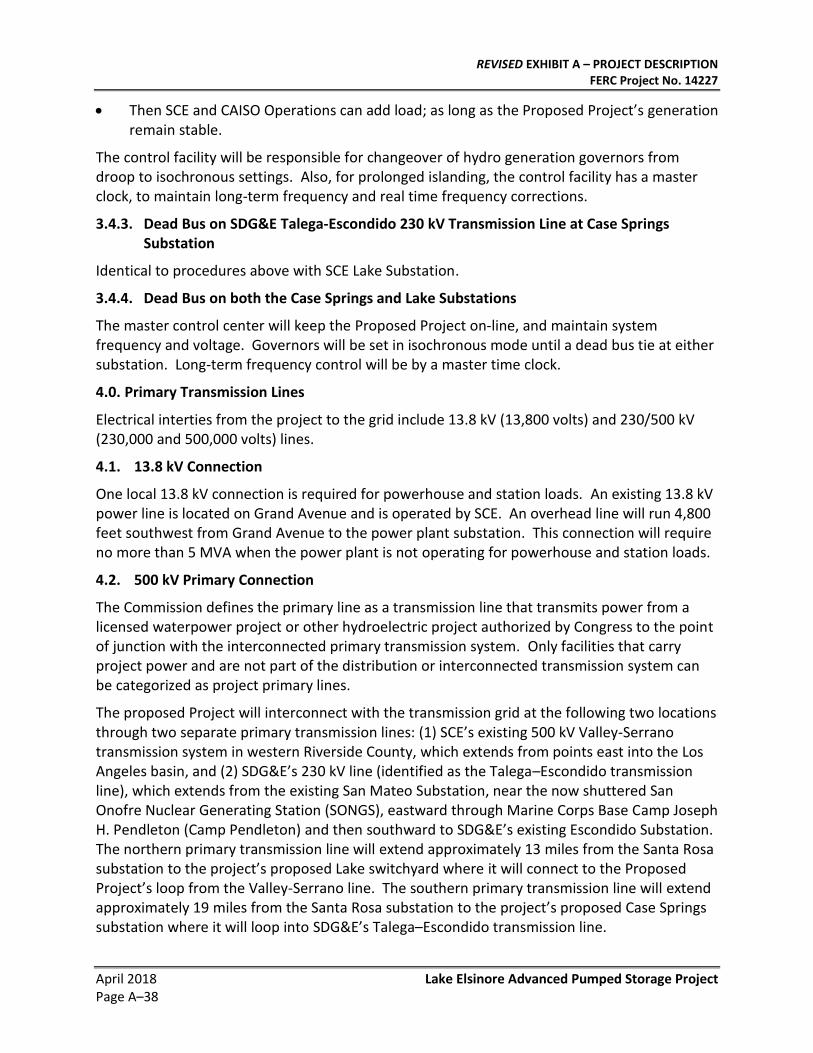
REVISED EXHIBIT A – PROJECT DESCRIPTION FERC Project No. 14227
April 2018 Lake Elsinore Advanced Pumped Storage Project Page A–38
• Then SCE and CAISO Operations can add load; as long as the Proposed Project’s generation remain stable.
The control facility will be responsible for changeover of hydro generation governors from droop to isochronous settings. Also, for prolonged islanding, the control facility has a master clock, to maintain long-term frequency and real time frequency corrections.
3.4.3. Dead Bus on SDG&E Talega-Escondido 230 kV Transmission Line at Case Springs Substation
Identical to procedures above with SCE Lake Substation.
3.4.4. Dead Bus on both the Case Springs and Lake Substations
The master control center will keep the Proposed Project on-line, and maintain system frequency and voltage. Governors will be set in isochronous mode until a dead bus tie at either substation. Long-term frequency control will be by a master time clock.
4.0. Primary Transmission Lines
Electrical interties from the project to the grid include 13.8 kV (13,800 volts) and 230/500 kV (230,000 and 500,000 volts) lines.
4.1. 13.8 kV Connection
One local 13.8 kV connection is required for powerhouse and station loads. An existing 13.8 kV power line is located on Grand Avenue and is operated by SCE. An overhead line will run 4,800 feet southwest from Grand Avenue to the power plant substation. This connection will require no more than 5 MVA when the power plant is not operating for powerhouse and station loads.
4.2. 500 kV Primary Connection
The Commission defines the primary line as a transmission line that transmits power from a licensed waterpower project or other hydroelectric project authorized by Congress to the point of junction with the interconnected primary transmission system. Only facilities that carry project power and are not part of the distribution or interconnected transmission system can be categorized as project primary lines.
The proposed Project will interconnect with the transmission grid at the following two locations through two separate primary transmission lines: (1) SCE’s existing 500 kV Valley-Serrano transmission system in western Riverside County, which extends from points east into the Los Angeles basin, and (2) SDG&E’s 230 kV line (identified as the Talega–Escondido transmission line), which extends from the existing San Mateo Substation, near the now shuttered San Onofre Nuclear Generating Station (SONGS), eastward through Marine Corps Base Camp Joseph H. Pendleton (Camp Pendleton) and then southward to SDG&E’s existing Escondido Substation. The northern primary transmission line will extend approximately 13 miles from the Santa Rosa substation to the project’s proposed Lake switchyard where it will connect to the Proposed Project’s loop from the Valley-Serrano line. The southern primary transmission line will extend approximately 19 miles from the Santa Rosa substation to the project’s proposed Case Springs substation where it will loop into SDG&E’s Talega–Escondido transmission line.
REVISED EXHIBIT A – PROJECT DESCRIPTION FERC Project No. 14227
Lake Elsinore Advanced Pumped Storage Project April 2018 Page A–39
Isolating circuit breakers, as well as the proposed use of phase shifting transformers at the Case Springs Substation, will prevent system power flow between the Lake and Case Springs Substations. Isolating circuit breakers will be installed so that the Project can only utilize either the north or south 500 kV line at a time. The circuit breakers and/or phase shifting transformers will allow the proposed Project to obtain pumping power from either SCE or SDG&E and will restrict the flow of that pumping power to the Santa Rosa Substation only. For example, no power from the Lake Substation used for pumping will be delivered to the Case Springs Substation. The circuit breakers and phase shifting transformers will also allow the Applicant to deliver project power to either the Lake or the Case Springs Substation. When flow is from the proposed Project to these substations, only project power or station power will be transmitted on the 500 kV LEAPS generator tie lines.
As configured, these primary transmission lines will not permit non–project power to flow between SCE and SDG&E.
The following figures provide electrical representations of these connections:
Figure A- 3: Project Conceptual Single Line Diagram
Figure A- 13: Santa Rosa Substation Drawings provides five views of the Santa Rosa substation. See Exhibit F for design details on this substation.
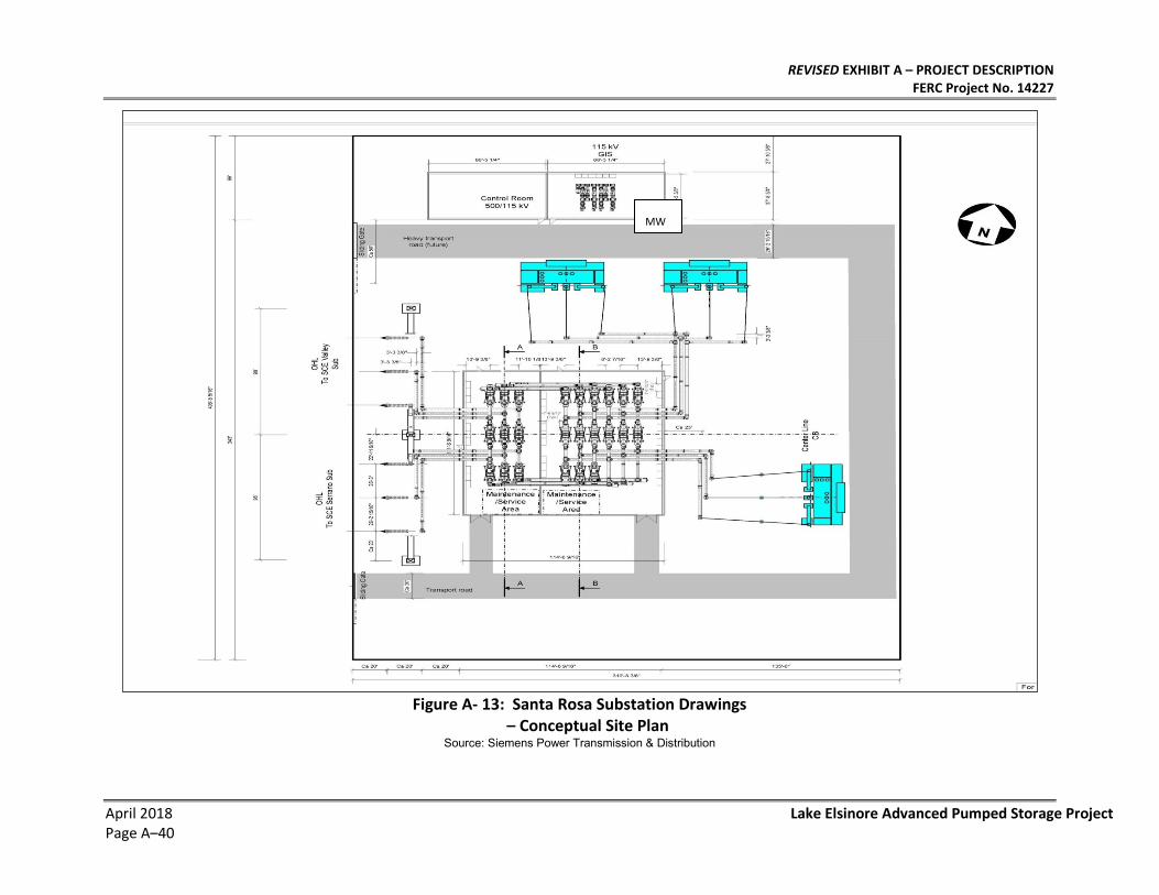
REVISED EXHIBIT A – PROJECT DESCRIPTION FERC Project No. 14227
April 2018 Lake Elsinore Advanced Pumped Storage Project Page A–40
Figure A- 13: Santa Rosa Substation Drawings
– Conceptual Site Plan Source: Siemens Power Transmission & Distribution
MW
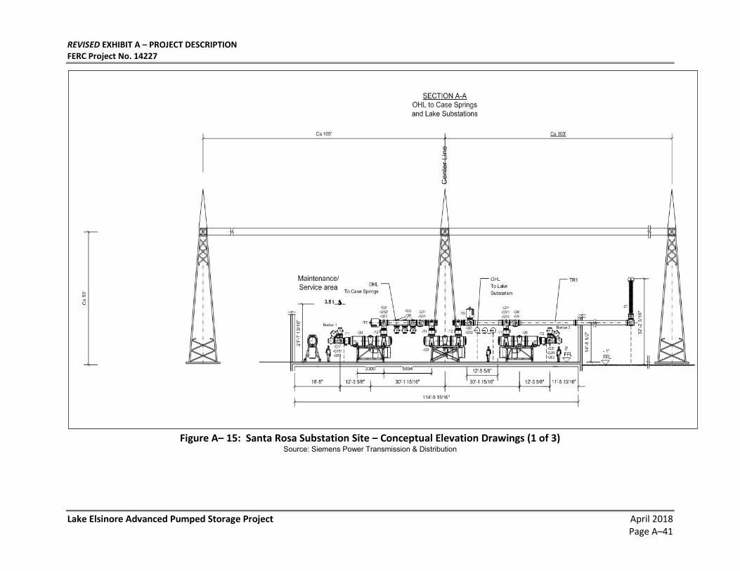
REVISED EXHIBIT A – PROJECT DESCRIPTION FERC Project No. 14227
Lake Elsinore Advanced Pumped Storage Project April 2018 Page A–41
Figure A– 15: Santa Rosa Substation Site – Conceptual Elevation Drawings (1 of 3)
Source: Siemens Power Transmission & Distribution
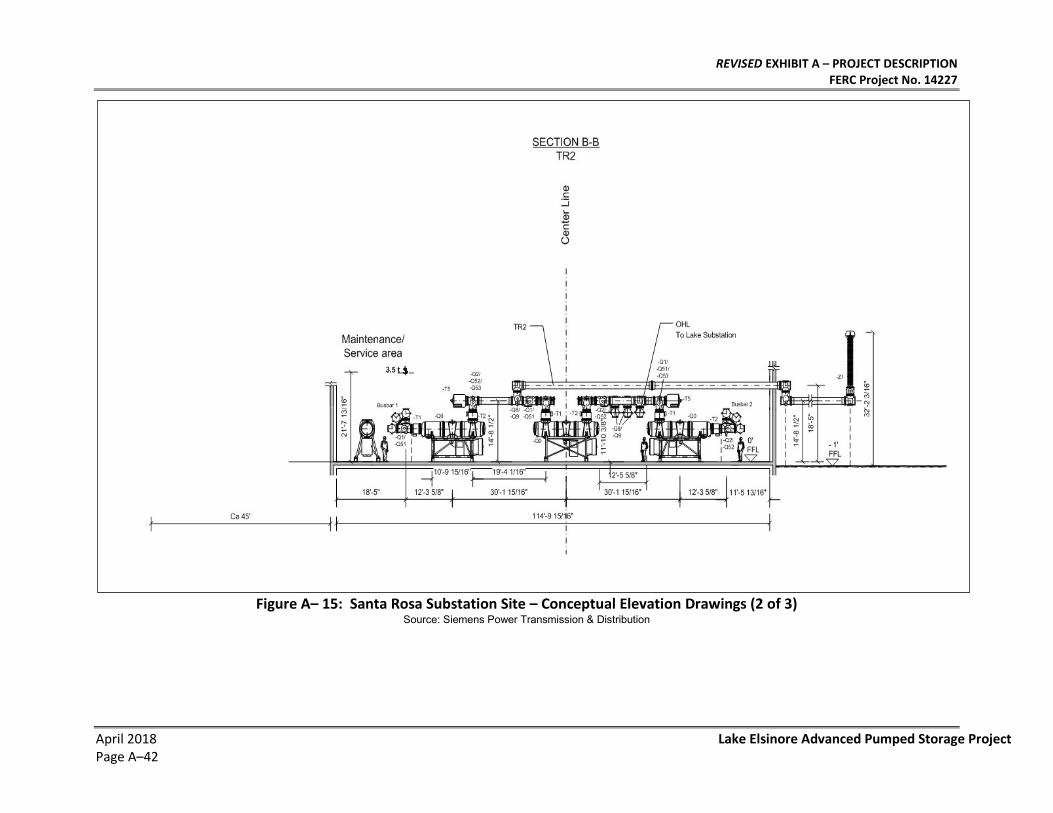
REVISED EXHIBIT A – PROJECT DESCRIPTION FERC Project No. 14227
April 2018 Lake Elsinore Advanced Pumped Storage Project Page A–42
Figure A– 15: Santa Rosa Substation Site – Conceptual Elevation Drawings (2 of 3)
Source: Siemens Power Transmission & Distribution
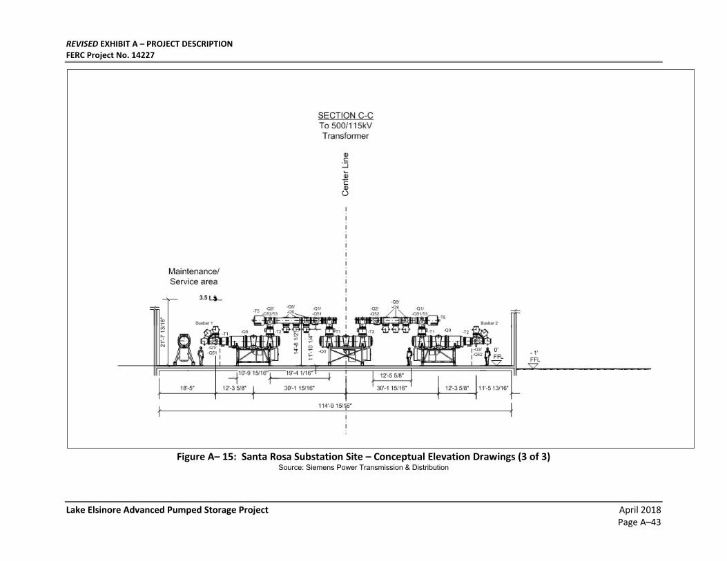
REVISED EXHIBIT A – PROJECT DESCRIPTION FERC Project No. 14227
Lake Elsinore Advanced Pumped Storage Project April 2018 Page A–43
Figure A– 15: Santa Rosa Substation Site – Conceptual Elevation Drawings (3 of 3)
Source: Siemens Power Transmission & Distribution

REVISED EXHIBIT A – PROJECT DESCRIPTION FERC Project No. 14227
April 2018 Lake Elsinore Advanced Pumped Storage Project Page A–44
Figure A– 15: Santa Rosa Substation Single Line Diagram
Source: Siemens Power Transmission & Distribution
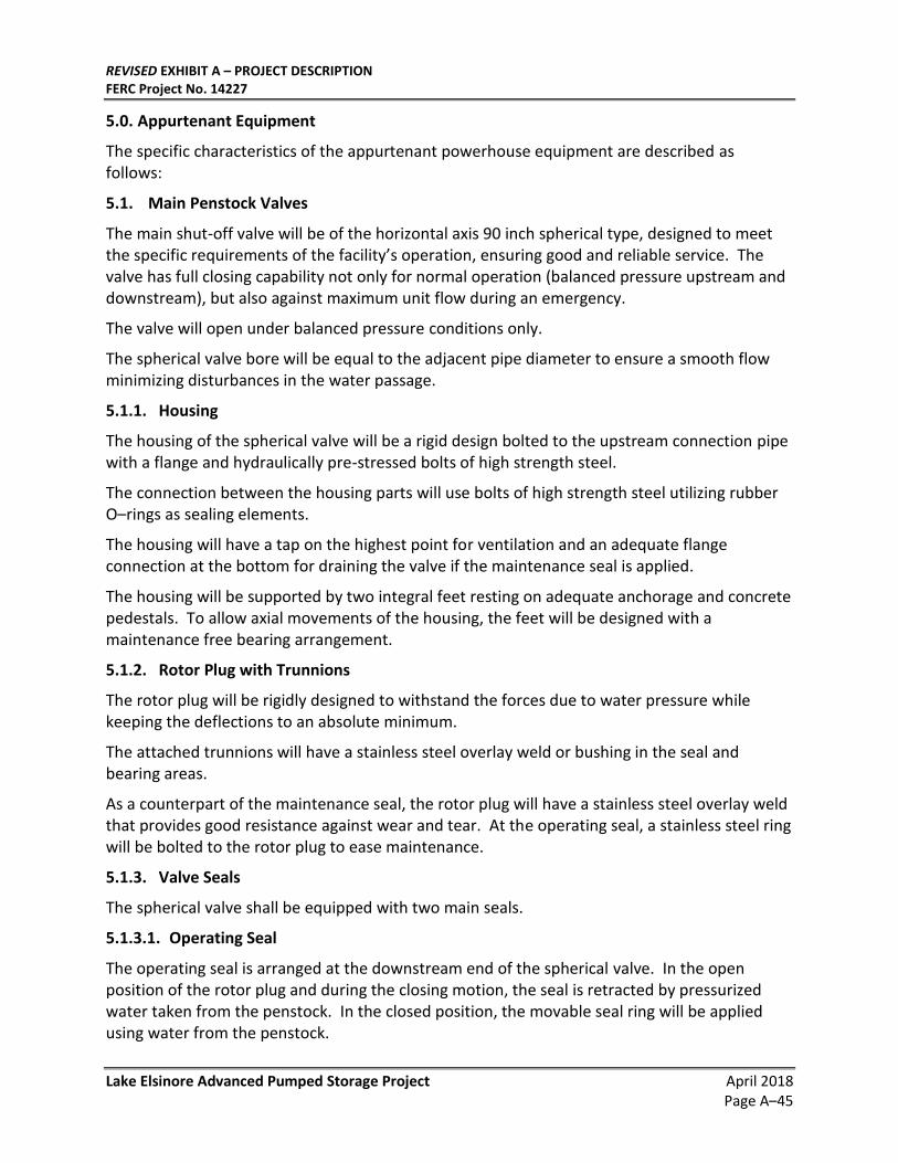
REVISED EXHIBIT A – PROJECT DESCRIPTION FERC Project No. 14227
Lake Elsinore Advanced Pumped Storage Project April 2018 Page A–45
5.0. Appurtenant Equipment
The specific characteristics of the appurtenant powerhouse equipment are described as follows:
5.1. Main Penstock Valves
The main shut-off valve will be of the horizontal axis 90 inch spherical type, designed to meet the specific requirements of the facility’s operation, ensuring good and reliable service. The valve has full closing capability not only for normal operation (balanced pressure upstream and downstream), but also against maximum unit flow during an emergency.
The valve will open under balanced pressure conditions only.
The spherical valve bore will be equal to the adjacent pipe diameter to ensure a smooth flow minimizing disturbances in the water passage.
5.1.1. Housing
The housing of the spherical valve will be a rigid design bolted to the upstream connection pipe with a flange and hydraulically pre-stressed bolts of high strength steel.
The connection between the housing parts will use bolts of high strength steel utilizing rubber O–rings as sealing elements.
The housing will have a tap on the highest point for ventilation and an adequate flange connection at the bottom for draining the valve if the maintenance seal is applied.
The housing will be supported by two integral feet resting on adequate anchorage and concrete pedestals. To allow axial movements of the housing, the feet will be designed with a maintenance free bearing arrangement.
5.1.2. Rotor Plug with Trunnions
The rotor plug will be rigidly designed to withstand the forces due to water pressure while keeping the deflections to an absolute minimum.
The attached trunnions will have a stainless steel overlay weld or bushing in the seal and bearing areas.
As a counterpart of the maintenance seal, the rotor plug will have a stainless steel overlay weld that provides good resistance against wear and tear. At the operating seal, a stainless steel ring will be bolted to the rotor plug to ease maintenance.
5.1.3. Valve Seals
The spherical valve shall be equipped with two main seals.
5.1.3.1. Operating Seal
The operating seal is arranged at the downstream end of the spherical valve. In the open position of the rotor plug and during the closing motion, the seal is retracted by pressurized water taken from the penstock. In the closed position, the movable seal ring will be applied using water from the penstock.
REVISED EXHIBIT A – PROJECT DESCRIPTION FERC Project No. 14227
April 2018 Lake Elsinore Advanced Pumped Storage Project Page A–46
The seal consists of a “T”–shaped movable seal ring of bronze, which is pressed against a stainless steel ring bolted to the rotor plug thus providing a good metallic seal. The movable seal ring is recessed in the housing and will be equipped with specially designed seals that incorporate a Teflon seal in combination with a flexible element for pre-stressing the seal to ensure a good seal. The mating surfaces in the housing will be of stainless steel to reduce the risk of sizing and galling.
Figure A- 14 illustrates a typical design.
Figure A- 14: Typical Operating Seal
Source: Voith Hydro
5.1.3.2. Maintenance Seal
The maintenance seal is arranged at the upstream end of the spherical valve. When applied, it will permit maintenance work on the operating seal at the downstream end of the valve. It will be applied by a manually operated hydraulic valve utilizing pressurized water from the penstock.
The seal consists of a “T”–shaped movable seal ring of bronze which is pressed against a stainless steel overlay area on the rotor plug thus providing a good metallic seal. The movable seal ring is recessed in the housing and will be equipped with an O-Ring type seal. The mating surfaces in the housing will be of stainless steel to reduce the risk of sizing and galling.
Figure A- 15 shows a typical design.
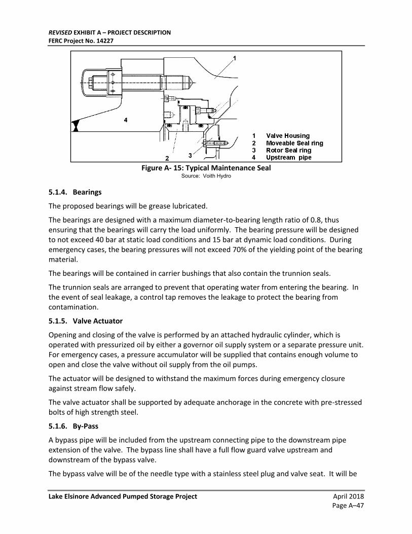
REVISED EXHIBIT A – PROJECT DESCRIPTION FERC Project No. 14227
Lake Elsinore Advanced Pumped Storage Project April 2018 Page A–47
Figure A- 15: Typical Maintenance Seal
Source: Voith Hydro
5.1.4. Bearings
The proposed bearings will be grease lubricated.
The bearings are designed with a maximum diameter-to-bearing length ratio of 0.8, thus ensuring that the bearings will carry the load uniformly. The bearing pressure will be designed to not exceed 40 bar at static load conditions and 15 bar at dynamic load conditions. During emergency cases, the bearing pressures will not exceed 70% of the yielding point of the bearing material.
The bearings will be contained in carrier bushings that also contain the trunnion seals.
The trunnion seals are arranged to prevent that operating water from entering the bearing. In the event of seal leakage, a control tap removes the leakage to protect the bearing from contamination.
5.1.5. Valve Actuator
Opening and closing of the valve is performed by an attached hydraulic cylinder, which is operated with pressurized oil by either a governor oil supply system or a separate pressure unit. For emergency cases, a pressure accumulator will be supplied that contains enough volume to open and close the valve without oil supply from the oil pumps.
The actuator will be designed to withstand the maximum forces during emergency closure against stream flow safely.
The valve actuator shall be supported by adequate anchorage in the concrete with pre-stressed bolts of high strength steel.
5.1.6. By-Pass
A bypass pipe will be included from the upstream connecting pipe to the downstream pipe extension of the valve. The bypass line shall have a full flow guard valve upstream and downstream of the bypass valve.
The bypass valve will be of the needle type with a stainless steel plug and valve seat. It will be
REVISED EXHIBIT A – PROJECT DESCRIPTION FERC Project No. 14227
April 2018 Lake Elsinore Advanced Pumped Storage Project Page A–48
operated hydraulically and be equipped with limit switches indicating the open and closed positions of the bypass.
The bypass valve will be sized adequately for pressurizing the spiral case to 80% of the penstock pressure assuming a wear of 0.05 mm in the gate mechanism of the pump turbine.
5.1.7. Control and Monitoring
For control and monitoring purposes, the valve will be equipped with the following instrumentation:
• 1 transducer indicating the position of the rotor plug;
• 6 limit switches, two each indicating open position, closed position and one intermediate position of the rotor plug;
• 4 pressure gauges with guard valves indicating the water pressures in the seal chambers;
• 1 pressure gauge with guard valve combined with a manual vent valve for indicating the pressure in the spherical valve;
• 1 pressure gauge with guard valve for indicating the pressure in the penstock;
• 1 pressure gauge with guard valve for indicating the pressure in the spiral case;
• 1 differential pressure switch providing an electrical signal for pressure equalization between penstock and spiral case; and
• 4 limit switches or signaling the positions of the operating seal and the maintenance seal movable seal rings.
5.1.8. Dismantling Joint
The dismantling pipe shall be flanged to the downstream end of the spherical valve. The design of the pipe will permit disassembly of the dismantling pipe with the valve closed.
The design will include a manhole with an internal diameter of 20 inches for inspection of the water passage upstream of the gate mechanism and downstream of the spherical valve. The manhole will be covered in the water passage with guiding plates to ensure proper flow through the dismantling pipe without disturbances.
On the downstream end, a dismantling joint will be arranged to accommodate axial movements of the valve caused by variations in water pressure.
The dismantling pipe will be fabricated from high strength steel and will be tested 100% by both radiographic inspection and magnetic particle testing for soundness of the weld seam, thus eliminating the necessity for a pressure test of this component.
5.1.9. Shop Assembly and Pressure Tests
The spherical valve will be assembled on site together with the upstream pipe extension.
The assembly will be filled with water, leakage tested at the maximum operating pressure and pressure tested for integrity at 1.5 times the maximum operating pressure. The pressure tests
REVISED EXHIBIT A – PROJECT DESCRIPTION FERC Project No. 14227
Lake Elsinore Advanced Pumped Storage Project April 2018 Page A–49
will be performed with the downstream seal being closed. For the tightness test of the maintenance seal, the maintenance seal will be closed and the maximum operating pressure will be applied upstream of the valve.
5.2. Draft Tube Bulkhead Gates
Draft tube bulkhead gates will be provided to be used in conjunction with the penstock valves for dewatering the pump-turbine water passages. The gates will be located in the surge chamber. One gate will be provided per unit with individual wire rope hoists located above maximum surge level.
5.3. Hoists and Cranes
The facility will have a single 400-ton capacity powerhouse crane with two 200-ton trolleys. The crane will be an overhead traveling bridge type and will be sized to handle the heaviest lift during equipment installation and maintenance.
5.4. Power Plant Mechanical Service Systems
5.4.1. Ventilation
The ventilation scheme maintains suitable conditions underground for the electrical and mechanical plant, ensures a safe working atmosphere for operation staff and provides comfortable conditions for operators and maintenance personnel.
Ambient conditions in the powerhouse will be governed by the temperature of the surrounding rock. The rock, which is at about 68°F, acts as an infinite heat sink for the various heat sources within the powerhouse, so that the powerhouse temperature will remain around 70°–80°F.
Ventilation air for the underground power facilities will be drawn down the ventilation shaft and discharged out the access shaft. The major heat–producing units such as transformers and generators will be cooled by oil-water and air-water heat exchanger systems, respectively, drawing cooling water from the lower reservoir. (In view of the corrosive properties of the Lake Elsinore water, sufficient corrosion allowance and/or corrosion-resistant materials will be used for all metal surfaces in contact with the water.) The high-voltage cables in the access shaft will be cooled by the flow of air through the tunnel. The air will be circulated through the transformer gallery, bus tunnels and powerhouse for fresh air makeup, and exhausted via a vent duct in the access shaft.
A system of ducting, bulkhead controls and circulating fans is required to ensure equitable distribution of air throughout the facility, especially to low-lying pockets liable to accumulate undesirable concentrations of carbon dioxide or other gases. Major fire doors, incorporating air locks, will be provided at key locations such as the bases of shafts and the access shaft from the powerhouse to the transformer gallery.
Local air conditioning will be provided in working areas such as the control room, lunchroom, etc.
5.4.2. Fire Protection
Fire protection systems in the underground plant will be of the conventional water deluge type
REVISED EXHIBIT A – PROJECT DESCRIPTION FERC Project No. 14227
April 2018 Lake Elsinore Advanced Pumped Storage Project Page A–50
for the major items of equipment such as transformers and generators. Water for the deluge systems will be taken from the lower reservoir, which is located some 250 feet above the turbines. Tied in with these deluge systems will be a system of isolating dampers and bulkheads connected to the ventilation exhaust system for control of smoke and fumes. The main generator transformers are totally enclosed in individual cells equipped with a deluge system. Auxiliary and excitation transformers will be nonflammable.
A higher pressure fire water system will supply water to fire hose stations located strategically throughout the power facilities. The water will be pressurized either directly with the fire pumps, or from a head tank excavated in rock that will be refueled by supply pumps.
5.4.3. Drainage and Dewatering
Normal station drainage of minor water leakage from equipment, groundwater seepage, etc. will be pumped to the tailrace tunnel by pumps operating from sumps in the powerhouse.
Unit dewatering will employ high-capacity pumps located in pressurized pump pits, the two pump-turbine units being interconnected by pipework in the low–level service galleries. Dewatering pumps will discharge into the tailrace tunnel.
5.4.4. Potable Water and Sanitary Services
Potable water required for the power plant and associated facilities will be purchased from the EVMWD. Sanitary wastes from the power plant and associated facilities will be pumped to the surface and transferred to the sewer system to be treated.
5.4.5. Compressed Air Systems
Separate compressed air systems will be furnished for the pump-turbine governor pressure systems, motor-generator brakes, tailwater depression and plant service air.
5.5. Power Plant Electrical and Control Systems
5.5.1. Power Plant Electrical Systems
The proposed single line for the Proposed Project is presented in Figure A- 3.
Each motor-generator unit is rated at 250 MW in the generating mode and 300 MW in the pumping mode. The machine voltage is 13.8 kV, with a power factor in the generating mode of 0.9 lagging.
Motor-generator synchronizing and phase reversal will be accomplished by a five-pole air blast circuit breaker located adjacent to each unit or in the above ground sub–station.
The motor-generator step-up transformers will be three-phase, 500 kV transformers each rated at 400 MVA, one transformer per unit. Transformers will be water cooled.
Power will be delivered between the surface and the transformers located underground via oil-filled cables. Circuit breakers and disconnects for the 500 kV cable to line transition will be located in a switchyard near the vertical access tunnel portal. Overhead transmission lines will interconnect to the existing 500 kV line, at a surface substation adjacent to the powerhouse.
Also enclosed in this substation are:
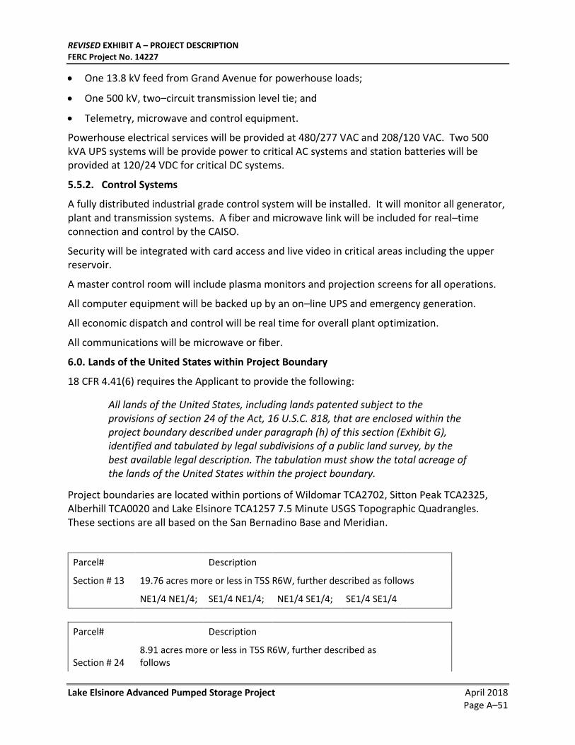
REVISED EXHIBIT A – PROJECT DESCRIPTION FERC Project No. 14227
Lake Elsinore Advanced Pumped Storage Project April 2018 Page A–51
• One 13.8 kV feed from Grand Avenue for powerhouse loads;
• One 500 kV, two–circuit transmission level tie; and
• Telemetry, microwave and control equipment.
Powerhouse electrical services will be provided at 480/277 VAC and 208/120 VAC. Two 500 kVA UPS systems will be provide power to critical AC systems and station batteries will be provided at 120/24 VDC for critical DC systems.
5.5.2. Control Systems
A fully distributed industrial grade control system will be installed. It will monitor all generator, plant and transmission systems. A fiber and microwave link will be included for real–time connection and control by the CAISO.
Security will be integrated with card access and live video in critical areas including the upper reservoir.
A master control room will include plasma monitors and projection screens for all operations.
All computer equipment will be backed up by an on–line UPS and emergency generation.
All economic dispatch and control will be real time for overall plant optimization.
All communications will be microwave or fiber.
6.0. Lands of the United States within Project Boundary
18 CFR 4.41(6) requires the Applicant to provide the following:
All lands of the United States, including lands patented subject to the provisions of section 24 of the Act, 16 U.S.C. 818, that are enclosed within the project boundary described under paragraph (h) of this section (Exhibit G), identified and tabulated by legal subdivisions of a public land survey, by the best available legal description. The tabulation must show the total acreage of the lands of the United States within the project boundary.
Project boundaries are located within portions of Wildomar TCA2702, Sitton Peak TCA2325, Alberhill TCA0020 and Lake Elsinore TCA1257 7.5 Minute USGS Topographic Quadrangles. These sections are all based on the San Bernadino Base and Meridian.
Parcel# Description
Section # 13 19.76 acres more or less in T5S R6W, further described as follows
NE1/4 NE1/4; SE1/4 NE1/4; NE1/4 SE1/4; SE1/4 SE1/4
Parcel# Description
Section # 24 8.91 acres more or less in T5S R6W, further described as follows
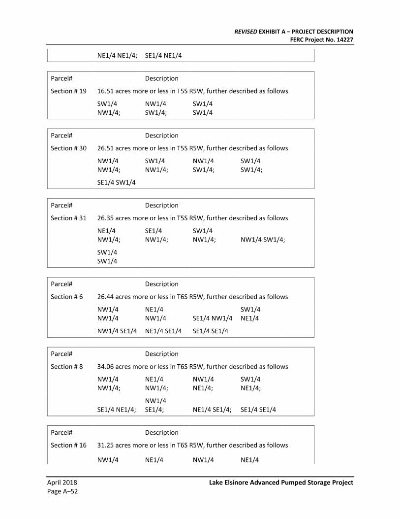
REVISED EXHIBIT A – PROJECT DESCRIPTION FERC Project No. 14227
April 2018 Lake Elsinore Advanced Pumped Storage Project Page A–52
NE1/4 NE1/4; SE1/4 NE1/4
Parcel# Description
Section # 19 16.51 acres more or less in T5S R5W, further described as follows
SW1/4 NW1/4;
NW1/4 SW1/4;
SW1/4 SW1/4
Parcel# Description
Section # 30 26.51 acres more or less in T5S R5W, further described as follows
NW1/4 NW1/4;
SW1/4 NW1/4;
NW1/4 SW1/4;
SW1/4 SW1/4;
SE1/4 SW1/4
Parcel# Description
Section # 31 26.35 acres more or less in T5S R5W, further described as follows
NE1/4 NW1/4;
SE1/4 NW1/4;
SW1/4 NW1/4; NW1/4 SW1/4;
SW1/4 SW1/4
Parcel# Description
Section # 6 26.44 acres more or less in T6S R5W, further described as follows
NW1/4 NW1/4
NE1/4 NW1/4 SE1/4 NW1/4
SW1/4 NE1/4
NW1/4 SE1/4 NE1/4 SE1/4 SE1/4 SE1/4
Parcel# Description
Section # 8 34.06 acres more or less in T6S R5W, further described as follows
NW1/4 NW1/4;
NE1/4 NW1/4;
NW1/4 NE1/4;
SW1/4 NE1/4;
SE1/4 NE1/4; NW1/4 SE1/4; NE1/4 SE1/4; SE1/4 SE1/4
Parcel# Description
Section # 16 31.25 acres more or less in T6S R5W, further described as follows
NW1/4 NE1/4 NW1/4 NE1/4
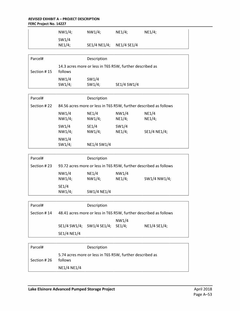
REVISED EXHIBIT A – PROJECT DESCRIPTION FERC Project No. 14227
Lake Elsinore Advanced Pumped Storage Project April 2018 Page A–53
NW1/4; NW1/4; NE1/4; NE1/4;
SW1/4 NE1/4; SE1/4 NE1/4; NE1/4 SE1/4
Parcel# Description
Section # 15 14.3 acres more or less in T6S R5W, further described as follows
NW1/4 SW1/4;
SW1/4 SW1/4; SE1/4 SW1/4
Parcel# Description
Section # 22 84.56 acres more or less in T6S R5W, further described as follows
NW1/4 NW1/4;
NE1/4 NW1/4;
NW1/4 NE1/4;
NE1/4 NE1/4;
SW1/4 NW1/4;
SE1/4 NW1/4;
SW1/4 NE1/4; SE1/4 NE1/4;
NW1/4 SW1/4; NE1/4 SW1/4
Parcel# Description
Section # 23 93.72 acres more or less in T6S R5W, further described as follows
NW1/4 NW1/4;
NE1/4 NW1/4;
NW1/4 NE1/4; SW1/4 NW1/4;
SE1/4 NW1/4; SW1/4 NE1/4
Parcel# Description
Section # 14 48.41 acres more or less in T6S R5W, further described as follows
SE1/4 SW1/4; SW1/4 SE1/4; NW1/4 SE1/4; NE1/4 SE1/4;
SE1/4 NE1/4
Parcel# Description
Section # 26 5.74 acres more or less in T6S R5W, further described as follows
NE1/4 NE1/4
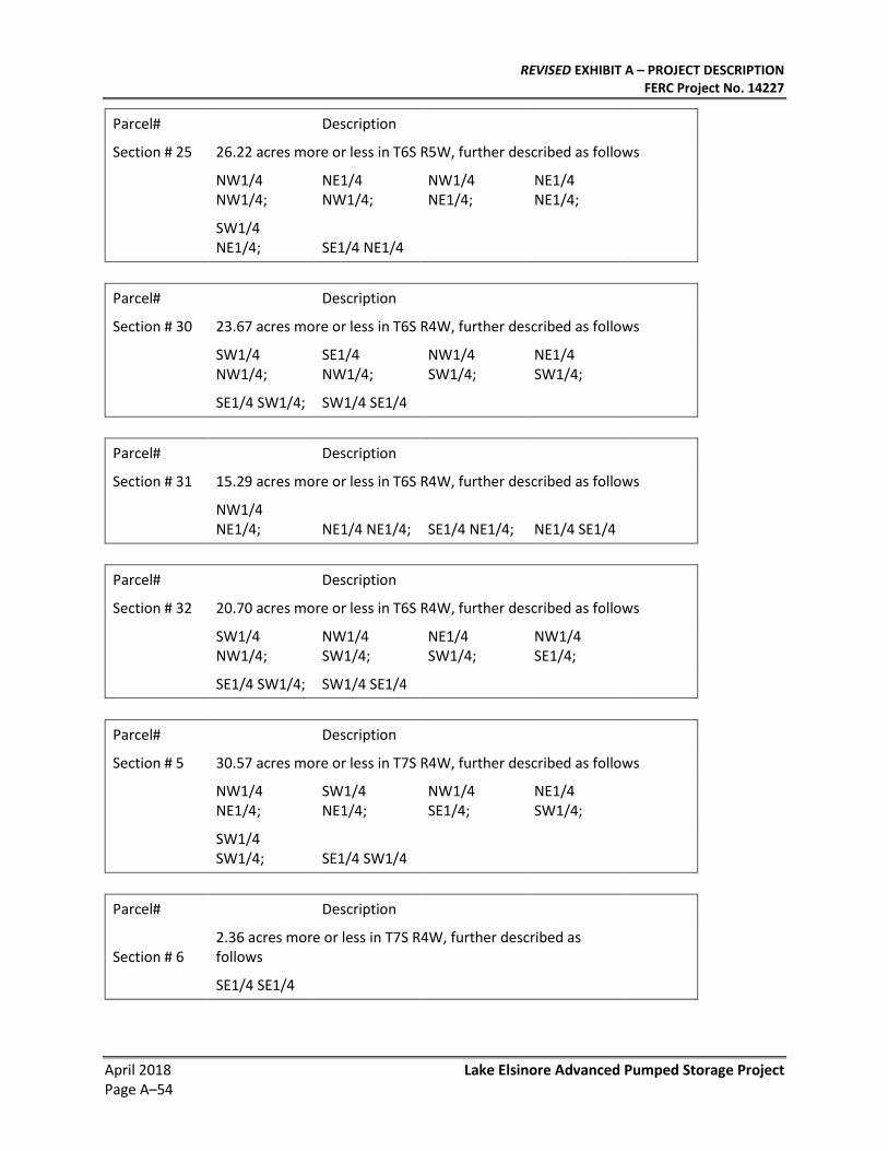
REVISED EXHIBIT A – PROJECT DESCRIPTION FERC Project No. 14227
April 2018 Lake Elsinore Advanced Pumped Storage Project Page A–54
Parcel# Description
Section # 25 26.22 acres more or less in T6S R5W, further described as follows
NW1/4 NW1/4;
NE1/4 NW1/4;
NW1/4 NE1/4;
NE1/4 NE1/4;
SW1/4 NE1/4; SE1/4 NE1/4
Parcel# Description
Section # 30 23.67 acres more or less in T6S R4W, further described as follows
SW1/4 NW1/4;
SE1/4 NW1/4;
NW1/4 SW1/4;
NE1/4 SW1/4;
SE1/4 SW1/4; SW1/4 SE1/4
Parcel# Description
Section # 31 15.29 acres more or less in T6S R4W, further described as follows
NW1/4 NE1/4; NE1/4 NE1/4; SE1/4 NE1/4; NE1/4 SE1/4
Parcel# Description
Section # 32 20.70 acres more or less in T6S R4W, further described as follows
SW1/4 NW1/4;
NW1/4 SW1/4;
NE1/4 SW1/4;
NW1/4 SE1/4;
SE1/4 SW1/4; SW1/4 SE1/4
Parcel# Description
Section # 5 30.57 acres more or less in T7S R4W, further described as follows
NW1/4 NE1/4;
SW1/4 NE1/4;
NW1/4 SE1/4;
NE1/4 SW1/4;
SW1/4 SW1/4; SE1/4 SW1/4
Parcel# Description
Section # 6 2.36 acres more or less in T7S R4W, further described as follows
SE1/4 SE1/4
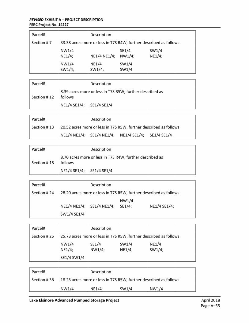
REVISED EXHIBIT A – PROJECT DESCRIPTION FERC Project No. 14227
Lake Elsinore Advanced Pumped Storage Project April 2018 Page A–55
Parcel# Description
Section # 7 33.38 acres more or less in T7S R4W, further described as follows
NW1/4 NE1/4; NE1/4 NE1/4;
SE1/4 NW1/4;
SW1/4 NE1/4;
NW1/4 SW1/4;
NE1/4 SW1/4;
SW1/4 SW1/4
Parcel# Description
Section # 12 8.39 acres more or less in T7S R5W, further described as follows
NE1/4 SE1/4; SE1/4 SE1/4
Parcel# Description
Section # 13 20.52 acres more or less in T7S R5W, further described as follows
NE1/4 NE1/4; SE1/4 NE1/4; NE1/4 SE1/4; SE1/4 SE1/4
Parcel# Description
Section # 18 8.70 acres more or less in T7S R4W, further described as follows
NE1/4 SE1/4; SE1/4 SE1/4
Parcel# Description
Section # 24 28.20 acres more or less in T7S R5W, further described as follows
NE1/4 NE1/4; SE1/4 NE1/4; NW1/4 SE1/4; NE1/4 SE1/4;
SW1/4 SE1/4
Parcel# Description
Section # 25 25.73 acres more or less in T7S R5W, further described as follows
NW1/4 NE1/4;
SE1/4 NW1/4;
SW1/4 NE1/4;
NE1/4 SW1/4;
SE1/4 SW1/4
Parcel# Description
Section # 36 18.23 acres more or less in T7S R5W, further described as follows
NW1/4 NE1/4 SW1/4 NW1/4
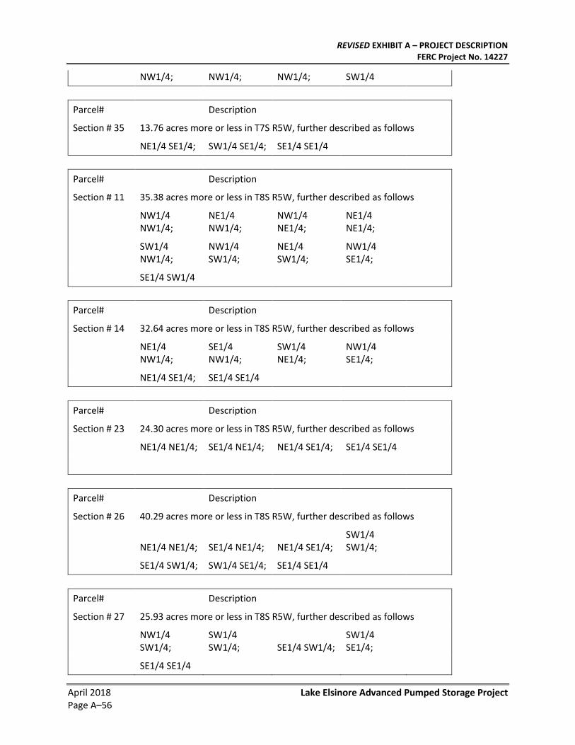
REVISED EXHIBIT A – PROJECT DESCRIPTION FERC Project No. 14227
April 2018 Lake Elsinore Advanced Pumped Storage Project Page A–56
NW1/4; NW1/4; NW1/4; SW1/4
Parcel# Description
Section # 35 13.76 acres more or less in T7S R5W, further described as follows
NE1/4 SE1/4; SW1/4 SE1/4; SE1/4 SE1/4
Parcel# Description
Section # 11 35.38 acres more or less in T8S R5W, further described as follows
NW1/4 NW1/4;
NE1/4 NW1/4;
NW1/4 NE1/4;
NE1/4 NE1/4;
SW1/4 NW1/4;
NW1/4 SW1/4;
NE1/4 SW1/4;
NW1/4 SE1/4;
SE1/4 SW1/4
Parcel# Description
Section # 14 32.64 acres more or less in T8S R5W, further described as follows
NE1/4 NW1/4;
SE1/4 NW1/4;
SW1/4 NE1/4;
NW1/4 SE1/4;
NE1/4 SE1/4; SE1/4 SE1/4
Parcel# Description
Section # 23 24.30 acres more or less in T8S R5W, further described as follows
NE1/4 NE1/4; SE1/4 NE1/4; NE1/4 SE1/4; SE1/4 SE1/4
Parcel# Description
Section # 26 40.29 acres more or less in T8S R5W, further described as follows
NE1/4 NE1/4; SE1/4 NE1/4; NE1/4 SE1/4; SW1/4 SW1/4;
SE1/4 SW1/4; SW1/4 SE1/4; SE1/4 SE1/4
Parcel# Description
Section # 27 25.93 acres more or less in T8S R5W, further described as follows
NW1/4 SW1/4;
SW1/4 SW1/4; SE1/4 SW1/4;
SW1/4 SE1/4;
SE1/4 SE1/4
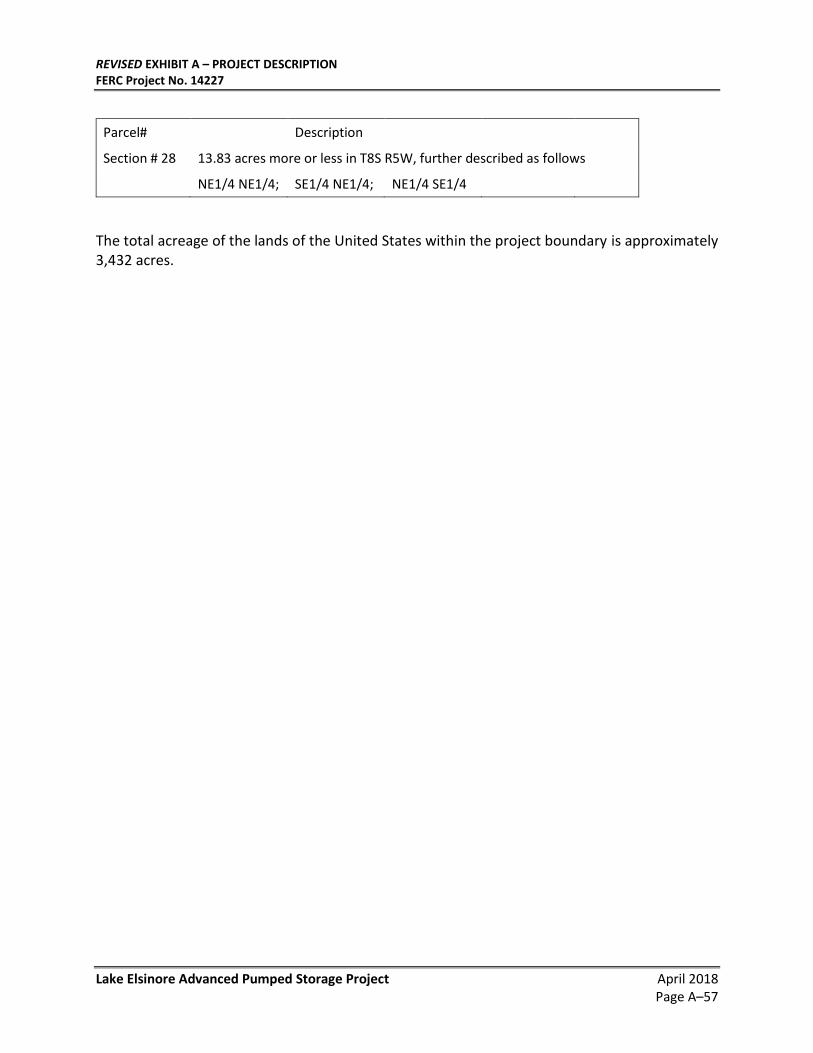
REVISED EXHIBIT A – PROJECT DESCRIPTION FERC Project No. 14227
Lake Elsinore Advanced Pumped Storage Project April 2018 Page A–57
Parcel# Description
Section # 28 13.83 acres more or less in T8S R5W, further described as follows
NE1/4 NE1/4; SE1/4 NE1/4; NE1/4 SE1/4
The total acreage of the lands of the United States within the project boundary is approximately 3,432 acres.
REVISED EXHIBIT A – PROJECT DESCRIPTION FERC Project No. 14227
April 2018 Lake Elsinore Advanced Pumped Storage Project Page A–58
This Page Intentionally Left Blank


![Servo Actuators FLA - Harmonic Drive SE · FLA Actuators without hollow shaft Table 14.1 Technical data Table 14.2 Symbol [Unit] FLA-11A-xxFB FLA-14A-xxFB FLA-17A-xxFB FLA-20A-xxFB](https://img.pdfslide.net/doc/110x75/5fd5fffdc37b2c5c172eeba3/servo-actuators-fla-harmonic-drive-se-fla-actuators-without-hollow-shaft-table.jpg)