Embed Size (px)
Citation preview
Attachments 1 and 2 to the Enclosure contain Proprietary Information -Withhold Under 10 CFR 2.390
Attachment 5PG&E Letter DCL-14-051
AREVA Calculation No. 32-9221082-001
Diablo Canyon Unit 2 Pressurizer Spray NozzleLaminar Flaw Analysis - Non Proprietary
Attachments 1 and 2 to the Enclosure contain Proprietary InformationWhen separated from Attachments 1 and 2, this document is decontrolled.
Controlled Document0402-01-FOl (Rev. 018, 01/30/2014)
A CALCULATION SUMMARY SHEET (CSS)AREVA
Document No. 32 - 9221082 - 001 Safety Related: EYes El No
Title Diablo Canyon Unit 2 Pressurizer Spray Nozzle Laminar Flaw Analysis - Non Proprietary
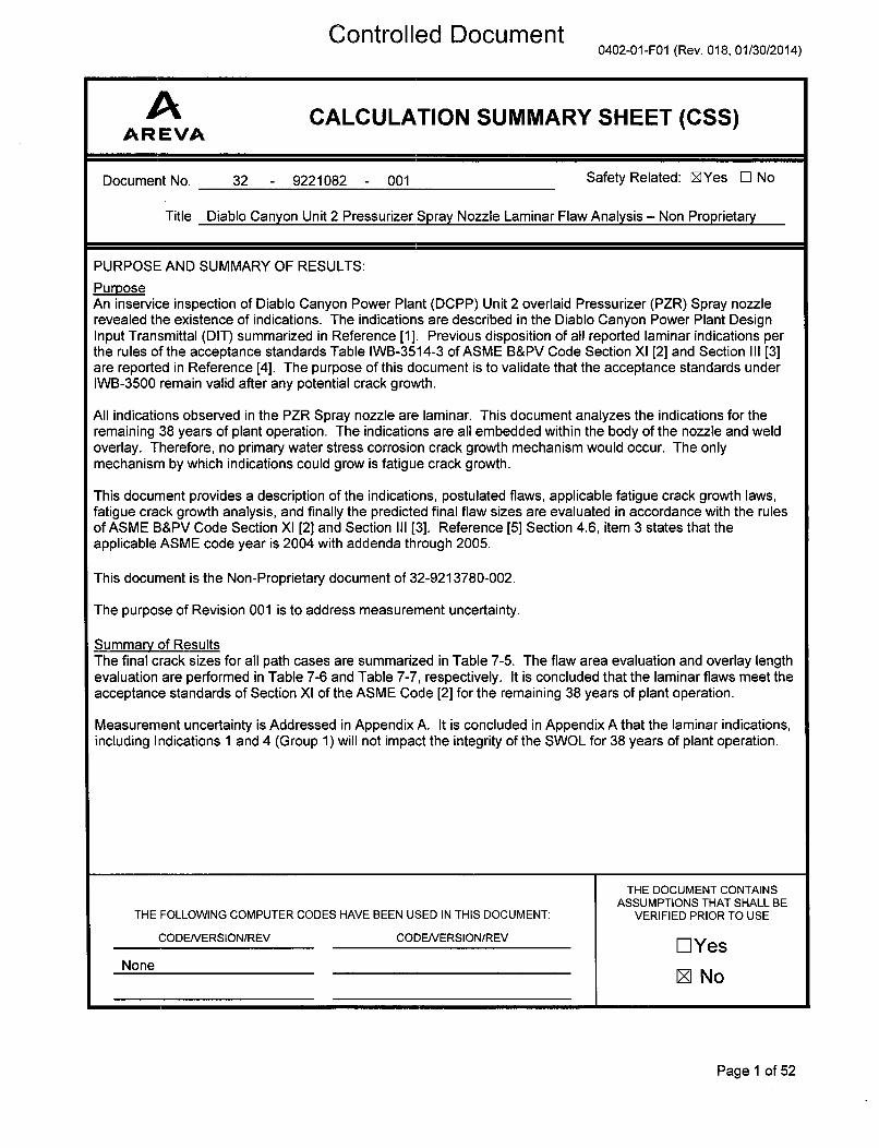
PURPOSE AND SUMMARY OF RESULTS:
PurposeAn inservice inspection of Diablo Canyon Power Plant (DCPP) Unit 2 overlaid Pressurizer (PZR) Spray nozzlerevealed the existence of indications. The indications are described in the Diablo Canyon Power Plant DesignInput Transmittal (DIT) summarized in Reference [1]. Previous disposition of all reported laminar indications perthe rules of the acceptance standards Table IWB-3514-3 of ASME B&PV Code Section XI [2] and Section III [3]are reported in Reference [4]. The purpose of this document is to validate that the acceptance standards underIWB-3500 remain valid after any potential crack growth.
All indications observed in the PZR Spray nozzle are laminar. This document analyzes the indications for theremaining 38 years of plant operation. The indications are all embedded within the body of the nozzle and weldoverlay. Therefore, no primary water stress corrosion crack growth mechanism would occur. The onlymechanism by which indications could grow is fatigue crack growth.
This document provides a description of the indications, postulated flaws, applicable fatigue crack growth laws,fatigue crack growth analysis, and finally the predicted final flaw sizes are evaluated in accordance with the rulesof ASME B&PV Code Section Xl [2] and Section III [3]. Reference [5] Section 4.6, item 3 states that theapplicable ASME code year is 2004 with addenda through 2005.
This document is the Non-Proprietary document of 32-9213780-002.
The purpose of Revision 001 is to address measurement uncertainty.
Summary of ResultsThe final crack sizes for all path cases are summarized in Table 7-5. The flaw area evaluation and overlay lengthevaluation are performed in Table 7-6 and Table 7-7, respectively. It is concluded that the laminar flaws meet theacceptance standards of Section XI of the ASME Code [2] for the remaining 38 years of plant operation.
Measurement uncertainty is Addressed in Appendix A. It is concluded in Appendix A that the laminar indications,including Indications 1 and 4 (Group 1) will not impact the integrity of the SWOL for 38 years of plant operation.
THE DOCUMENT CONTAINSASSUMPTIONS THAT SHALL BE
THE FOLLOWING COMPUTER CODES HAVE BEEN USED IN THIS DOCUMENT: VERIFIED PRIOR TO USE
CODE/VERSION/REV CODENERSION/REV E YesNone Z No
Page 1 of 52
C'r~r~+rr~llr~r 4 flr~r~. mmv~t,+%.0 %0 1 6 %L, I S %,A LS , .1 • d •. 6A I I I I I 1 16
AAREVA
0402-01-FOI (Rev. 018, 01/3012014)
Document No. 32-9221082-001
Diablo Canyon Unit 2 Pressurizer Spray Nozzle Laminar Flaw Analysis - Non Proprietary
Review Method: i'• Design Review (Detailed Check)
[] Alternate Calculation
Signature Block
PIR/AName and Title and PageslSections
(printed or typed) Signature LPILR Date PreparedlReviewedlApproved
Silvester J Noronha , .,¢A
Principal Engineer PAll.
Ashok D. Nana
Supervisory Engineer -R ____-Al
Tim M Wiger ) Ii P7 A All.Engineering Manager ._.
Note: P/R/A designates Preparer (P), Reviewer (R), Approver (A);LP/LR designates Lead Preparer (LP), Lead Reviewer (LR)
Project Manager Approval of Customer References (N/A if not applicable)
Name Title(printed or typed) (printed or typed) Signature Date
N/A N/A N/A N/A
Mentoring Information (not required per 0402-01)
Name Title Mentor to:(printed or typed) (printed or typed) (PIR) Signature Date
N/A N/A N/A N/A N/A
Page 2
Controlled Document
AAREVA
0402-01-FOl (Rev. 018, 01/30/2014)
Document No. 32-9221082-001
Diablo Canyon Unit 2 Pressurizer Spray Nozzle Laminar Flaw Analysis - Non Proprietary
Record of Revision
Revision PageslSectionslPa rag ra phsNo. Changed Brief Description / Change Authorization
000 All Original Release
001 Page 1 Added purpose and summary for Revision 001
Section 5.0 Listed new file
_________Appendix A Added Appendix A
_ _ I___ I _______
Page 3
Controlled Document
AAREVA Document No. 32-9221082-001
Diablo Canyon Unit 2 Pressurizer Spray Nozzle Laminar Flaw Analysis - Non Proprietary
Table of ContentsPage
SIG NATURE BLO CK ................................................................................................................................ 2
R ECO RD O F REV ISIO N .......................................................................................................................... 3
LIST O F TABLES ..................................................................................................................................... 6
LIST O F FIG UR ES ................................................................................................................................... 7
1.0 INTRO DUCTIO N ........................................................................................................................... 8
2.0 A NALYTICAL M ETHO DO LO G Y .............................................................................................. 9
2.1 Stress Intensity Factor Model ...................................................................................................... 9
2.2 Fatigue Crack Growth Calculation ............................................................................................ 11
2.3 Lam inar Flaw Evaluation ........................................................................................................... 11
2.4 M inim um Required Overlay Length Calculations ..................................................................... 12
2.5 List of Abbreviations and Parameters ........................................................................................ 13
3.0 A SSUM PTIO NS .......................................................................................................................... 15
3.1 Unverified Assum ptions .................................................................................................................. 15
3.2 Justified Assum ptions ..................................................................................................................... 15
3.3 M odeling Sim plifications ........................................................................................................... 15
4.0 DESIG N INPUTS ........................................................................................................................ 16
4 .1 G e o m e try ........................................................................................................................................ 16
4 .2 M a te ria l ........................................................................................................................................... 2 0
4.3 External Loads ............................................................................................................................... 20
4.4 Operating Transients ...................................................................................................................... 22
4.5 Operating Stresses ......................................................................................................................... 23
4.6 Operating Tem peratures ........................................................................................................... 27
4.7 Residual Stresses .......................................................................................................................... 27
4.8 Fatigue Crack Growth Laws ....................................................................................................... 28
4.8.1 [ ] (FSW OL) .................................................................................. 28
4.8.2 Stainless Steel I ) .....................................................[..................... . 29
4.8.3 Low-Alloy Steel ...........................................................(.[........................ . 30
Page 4
Controlled Document
AAR EVA Document No. 32-9221082-001
Diablo Canyon Unit 2 Pressurizer Spray Nozzle Laminar Flaw Analysis - Non Proprietary
Table of Contents(continued)
Page
5.0 COM PUTER USAGE .................................................................................................................. 32
5.1 Software and Hardware .................................................................................................................. 32
5 .2 C o m p ute r F ile s ............................................................................................................................... 3 2
6.0 CALCULATIONS ......................................................................................................................... 33
6.1 [ ] (W eld Overlay) ................................................................................................. 33
6.2 Stainless Steel (Pipe to Safe End W eld) ................................................................................... 34
6.3 Low-Alloy Steel ( [ ] Nozzle Material) ........................................................................ 36
7 .0 R E S U L T S .................................................................................................................................... 3 7
7.1 Fatigue Crack Growth .................................................................................................................... 37
7.2 Laminar Flaw Evaluation ........................................................................................................... 45
8.0 REFERENCES ............................................................................................................................. 48
APPENDIX A : FLAW SIZE UNCERTAINTY CONSIDERATION ................................................................... 50
Page 5
Controlled Document
AAREVA Document No. 32-9221082-001
Diablo Canyon Unit 2 Pressurizer Spray Nozzle Laminar Flaw Analysis - Non Proprietary
List of TablesPage
Table 4-1: S pray N ozzle D im ensions ................................................................................................. 16
Table 4-2: Dimensions for SIF Calculation ....................................................................................... 18
T a ble 4-3 : T a ble of M ate rials ................................................................................................................. 20
Table 4-4: PZR Spray Nozzle Sustained and Seismic Loading Conditions at Safe End Applicable toC ra ck G row th A na lys is ..................................................................................................................... 2 1
Table 4-5: PZR Spray Nozzle Sustained and Seismic Loading Conditions at Nozzle Applicable toC ra ck G row th A na ly sis ..................................................................................................................... 2 1
Table 4-6: PZR Spray Nozzle Sustained and Seismic Loading Conditions at Safe End Applicable toO v e rla y S iz in g .................................................................................................................................. 2 1
Table 4-7: PZR Spray Nozzle Sustained and Seismic Loading Conditions at Nozzle Applicable toO v e rla y S iz in g .................................................................................................................................. 2 2
Table 4-8: Operating Transients for PZR Spray Nozzle [7] ............................................................. 22
Table 4-9: Maximum and Minimum Stresses for Indications 1 and 4 (Pathline Fline2) .................... 25
Table 4-10: Maximum and Minimum Stresses for Indications 2 and 3 (Pathline Fline4) .................. 26
Table 4-11: Maximum Temperatures for Path Line Cases (Units: OF) .............................................. 27
Table 4-12: Bounding Radial and Shear Weld Residual Stresses for Laminar Flaws ...................... 28
T a ble 5-1: C o m p ute r F ile s ..................................................................................................................... 32
Table 7-1: Fatigue Crack Growth for Indications 1 and 4 (Case FL2_wol) ...................................... 37
Table 7-2: Fatigue Crack Growth for Indications 1 and 4 (Case FL2_noz) ....................................... 39
Table 7-3: Fatigue Crack Growth for Indications 2 and 3 (Case FL4_wol) ...................................... 41
Table 7-4: Fatigue Crack Growth for Indications 2 and 3 (FL4_wld) ............................................... 43
Table 7-5: Summary of Fatigue Crack Growth ................................................................................ 45
Table 7-6: Flaw A rea Evaluation ........................................................................................................ 46
Table 7-7: Overlay Length Evaluation ............................................. ................................................. 47
Table A-I: Results of Flaw Growth Analysis with [ ] in NDE Uncertainty ............................... 50
Table A-2: Laminar Area Evaluation with [ ] in NDE Uncertainty ........................................... 51
Table A-3: Overlay Length Evaluation with [ ] in NDE Uncertainty ......................................... 52
Page 6
Controlled Document
AAREVA Document No. 32-9221082-001
Diablo Canyon Unit 2 Pressurizer Spray Nozzle Laminar Flaw Analysis - Non Proprietary
List of FiguresPage
Figure 2-1: A Through-W all Crack in the Center of a Plate ............................................................. 10
Figure 4-1: Schematic of the Spray Nozzle with FSW OL ................................................................ 16
Figure 4-2: WIB-345 Overlay Rollout Spray Nozzle (Ref. [1]) ............................................................ 17
Figure 4-3: Spray Nozzle WIB-345 Overlay Indication Plot (Ref. [1]) ............................................... 17
Figure 4-4: Idealization of the CCP Model for the Spray Nozzle Indications .................................... 19
Figure 4-5: PZR Spray Nozzle with Path Lines Superposed ........................................................... 24
Page 7
Controlled Document
AAR EVA Document No. 32-9221082-001
Diablo Canyon Unit 2 Pressurizer Spray Nozzle Laminar Flaw Analysis - Non Proprietary
1.0 INTRODUCTION
An inservice inspection of Diablo Canyon Power Plant (DCPP) Unit 2 overlaid Pressurizer (PZR) Spraynozzle revealed the existence of indications. The indications are described in the Diablo CanyonPower Plant Design Input Transmittal (DIT) documented in Reference [1]. All indications found in thePZR Spray nozzle are laminar. Previous disposition of the as found laminar indications per the rules ofthe acceptance standards in Table IWB-3514-3 of the ASME B&PV Code Section Xl [2] and Article NB-3227.2 of ASME B&PV Code Section III [3] are documented in Reference [4]. Reference [4] did notconsider any potential flaw growth that may occur due to sustained and cyclic operating conditions.
The purpose of this document is to assess the flaw growth that could take place for the remaining 38years of plant operation. Because the laminar indications are located between the overlay and theoriginal underlying materials, the surfaces of the indications do not come in contact with the reactorcoolant. Therefore, no primary water stress corrosion crack (PWSCC) growth mechanism would occur.The only credible mechanism by which the indications could grow is fatigue crack growth.
This document provides a description of the indications, postulated flaws, applicable fatigue crackgrowth laws, fatigue crack growth analysis, and finally the predicted final flaw sizes are evaluated inaccordance with the rules of ASME B&PV Code Section XI [2] and Section III [3]. Reference [5]Section 4.6, item 3 states that the applicable ASME code year is 2004 with addenda through 2005.
Page 8
Controlled Document
AAR EVA Document No. 32-9221082-001
Diablo Canyon Unit 2 Pressurizer Spray Nozzle Laminar Flaw Analysis - Non Proprietary
2.0 ANALYTICAL METHODOLOGY
This document performs flaw evaluation for dispositioning the NDE found indication in the DCPP PZRSpray nozzle. As described in Reference [1], all indications were laminar in nature. Thus, thisdocument postulates cylindrical flaws to analyze all laminar indication.
For each postulated flaw, the flaw evaluation methodology consists of performing fatigue flaw growthfor the specified service life. At the end of life, a flaw evaluation is performed to evaluate the end of lifeflaw acceptability.
This analysis postulated cylindrical sub-surface flaws, which could propagate by fatigue crack growththrough the body of the Spray nozzle and full structural weld overlay (FSWOL). A linear elastic fracturemechanics (LEFM) analysis was performed to determine the applied stress intensity factors (SIFs) forthe laminar flaw indications. The center-cracked panel (CCP) model was used with the radial andshear stresses to compute stress intensity factors for the laminar flaw indications. Flaw growth in theaxial direction to estimate final flaw width was calculated using the SIF from the CCP model.Circumferential crack growth for estimating the final flaw length was evaluated by extending the flawlength in proportion to the ratio of final flaw width to the initial flaw width.
It should be noted that the planar flaw analysis for DCPP Unit 2 PZR nozzles [6] used 38 years ofremaining service life. The current analysis was performed using the 38 years of remaining service lifeas well. The crack growth analysis considered the growth of embedded flaws due to cyclic loadingsunder the presence of residual stress from the welding processes. The final flaw sizes were calculatedusing the same operating transients considered in the original 2007 flaw growth analysis [7]. Thepredicted final flaw sizes were evaluated in accordance with the rules of ASME B&PV Code Section XITable IWB-3514-3 [2]. Using Section III article NB-3227.2 [3], the presence of the laminar flaws wasevaluated to assess the ability of the weld overlay to perform its intended function. Section III articleNB-3227.2 [3] was used to verify that the weld overlay length excluding the indications is sufficient totransfer the load through shear back to the base metal considering a 100% through wall crack in thePWSCC susceptible material.
The initial structural overlay analysis was performed in 2007 per ASME Section III Subsection NB Codewith 2001 and 2003 Addenda. During relief request of 2013, the shear stress check for the laminar flawanalysis was performed per ASME Section III Subsection NB Code with 2004 and 2005 Addenda. BothCode years were reviewed and it was determined that the criteria for pure shear stress evaluation perNB-3227.2 are the same. Hence, it is concluded that both the Codes are applicable to the currentanalyses and no additional reconciliation is required.
The remainder of this section describes the model used to calculate the stress intensity factor (SIF),crack growth calculation procedure, flaw evaluation, FSWOL minimum length requirement evaluation,and a list of the abbreviations and parameters used throughout the document.
2.1 Stress Intensity Factor Model
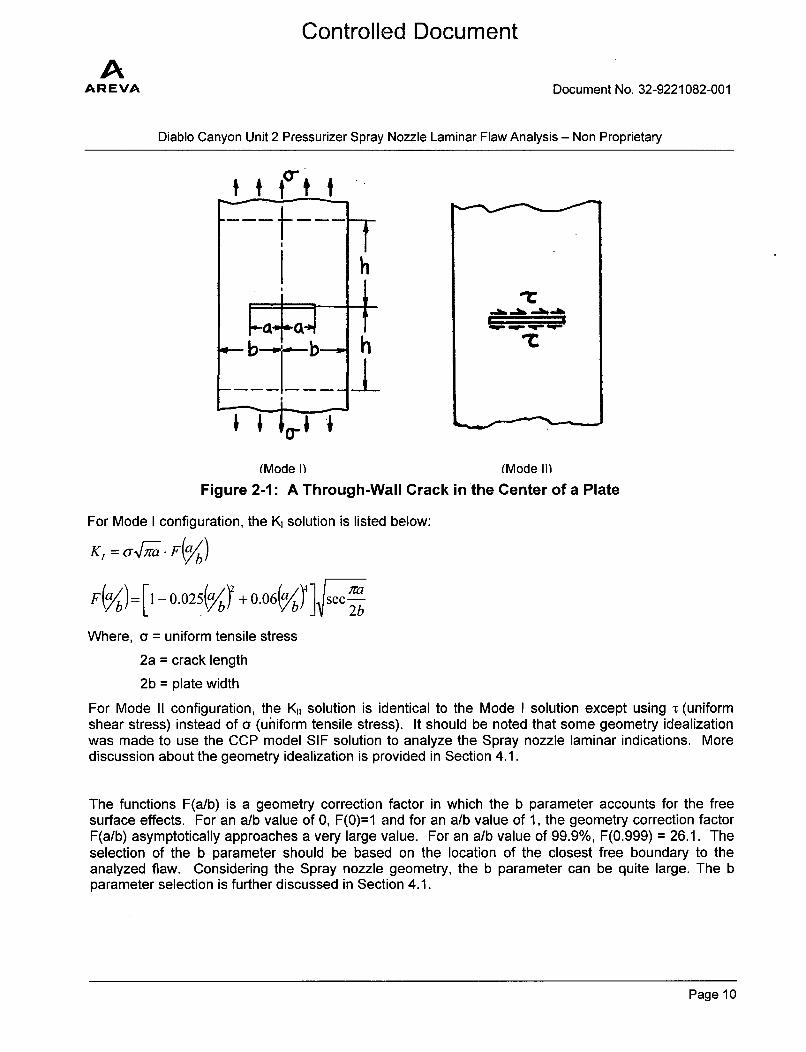
To calculate the stress intensity factor for the laminar flaw, the closed-form SIF solution from page 40 ofReference [8] for CCP model was used. The Mode I and Mode II configurations are illustrated in Figure2-1.
Page 9
Controlled Document
AAR EVA Document No. 32-9221082-001
Diablo Canyon Unit 2 Pressurizer Spray Nozzle Laminar Flaw Analysis - Non Proprietary
l.- ° t-' -" -'"-b-o. h -t
(Mode 1) (Mode II)Figure 2-1: A Through-Wall Crack in the Center of a Plate
For Mode I configuration, the K, solution is listed below:
KI = arma F(ab)
F(ab)= [1 - 0 .02 5.(alb + 0.06(alb)4 ] sec-•b
b L b+ bj 2b
Where, a = uniform tensile stress
2a = crack length
2b = plate width
For Mode II configuration, the K1, solution is identical to the Mode I solution except using 'r (uniformshear stress) instead of a (uniform tensile stress). It should be noted that some geometry idealizationwas made to use the CCP model SIF solution to analyze the Spray nozzle laminar indications. Morediscussion about the geometry idealization is provided in Section 4.1.
The functions F(a/b) is a geometry correction factor in which the b parameter accounts for the freesurface effects. For an a/b value of 0, F(0)=1 and for an a/b value of 1, the geometry correction factorF(a/b) asymptotically approaches a very large value. For an a/b value of 99.9%, F(0.999) = 26.1. Theselection of the b parameter should be based on the location of the closest free boundary to theanalyzed flaw. Considering the Spray nozzle geometry, the b parameter can be quite large. The bparameter selection is further discussed in Section 4.1.
Page 10
Controlled Document
AAREVA Document No. 32-9221082-001
Diablo Canyon Unit 2 Pressurizer Spray Nozzle Laminar Flaw Analysis - Non Proprietary
2.2 Fatigue Crack Growth Calculation
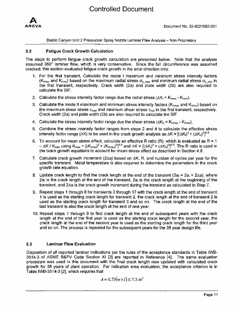
The steps to perform fatigue crack growth calculation are presented below. Note that the analysisassumed 3600 laminar flaw, which is very conservative. Since the full circumference was assumedcracked; this section evaluated fatigue crack growth in the axial direction only.
1. For the first transient, Calculate the mode I maximum and minimum stress intensity factors(Kimax and Kimin) based on the maximum radial stress Ox_max and minimum radial stress Ox_min inthe first transient, respectively. Crack width (2a) and plate width (2b) are also required tocalculate the SIF.
2. Calculate the stress intensity factor range due the radial stress (AKI = Klmax - Klmin).
3. Calculate the mode II maximum and minimum stress intensity factors (KIimax and Kilmin) based onthe maximum shear stress Tmax and minimum shear stress tCmin in the first transient, respectively.Crack width (2a) and plate width (2b) are also required to calculate the SIF.
4. Calculate the stress intensity factor range due the shear stress (AKI = Kimrax - Kiimin).
5. Combine the stress intensity factor ranges from steps 2 and 4 to calculate the effective stressintensity factor range (AK) to be used in the crack growth analysis as AK = [(AKI) 2 + (AK1) 2]0 5.
6. To account for mean stress effect, calculate an effective R ratio (R), which is evaluated as R = 1- AK / Kmax using Kmax = [(Kimax) 2 + (Kirmax) 2 ]0 5 and AK = [(AK,)2 + (AK,1)2]05 . The R ratio is used inthe crack growth equations to account for mean stress effect as described in Section 4.8.
7. Calculate crack growth increment (2Aa) based on AK, R, and number of cycles per year for thespecific transient. Metal temperature is also required to determine the parameters in the crackgrowth rate equation.
8. Update crack length to find the crack length at the end of the transient (2 af = 2ai + 2Aa), where2af is the crack length at the end of the transient, 2ai is the crack length at the beginning of thetransient, and 2Aa is the crack growth increment during the transient as calculated in Step 7.
9. Repeat steps 1 through 8 for transients 2 through 17 with the crack length at the end of transient1 is used as the starting crack length for transient 2, the crack length at the end of transient 2 isused as the starting crack length for transient 3 and so on. The crack length at the end of thelast transient is also the crack length at the end of one year.
10. Repeat steps 1 through 9 to find crack length at the end of subsequent years with the cracklength at the end of the first year is used as the starting crack length for the second year, thecrack length at the end of the second year is used as the starting crack length for the third yearand so on. The process is repeated for the subsequent years for the 38 year design life.
2.3 Laminar Flaw Evaluation
Disposition of all reported laminar indications per the rules of the acceptance standards in Table IWB-3514-3 of ASME B&PV Code Section Xl [2] are reported in Reference [4]. The same evaluationprocedure was used in this document with the final crack length now updated with calculated crackgrowth for 38 years of plant operation. For indication area evaluation, the acceptance criterion is inTable IWB-3514-3 [2], which requires that
A = 0.75(wxl) < 7.5 in2
Page 11
Controlled Document
AAR EVA Document No. 32-9221082-001
Diablo Canyon Unit 2 Pressurizer Spray Nozzle Laminar Flaw Analysis - Non Proprietary
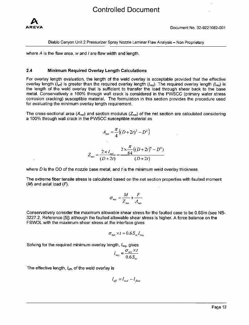
where A is the flaw area, w and I are flaw width and length.
2.4 Minimum Required Overlay Length Calculations
For overlay length evaluation, the length of the weld overlay is acceptable provided that the effectiveoverlay length (leff) is greater than the required overlay length (Ireq). The required overlay length (Ireq) isthe length of the weld overlay that is sufficient to transfer the load through shear back to the basemetal. Conservatively a 100% through wall crack is considered in the PWSCC (primary water stresscorrosion cracking) susceptible material. The formulation in this section provides the procedure usedfor evaluating the minimum overlay length requirement.
The cross-sectional area (Anet) and section modulus (Znet) of the net section are calculated consideringa 100% through wall crack in the PWSCC susceptible material as
Ane =-' ((D+ 2t)2-D2)
2x 2 x -T ((D + 2t)4 - D 4)
Z.e11 ne 64(D+2t) (D+2t)
where D is the OD of the nozzle base metal, and t is the minimum weld overlay thickness.
The extreme fiber tensile stress is calculated based on the net section properties with faulted moment(M) and axial load (F).
M F,- + -Znet Ane,
Conservatively consider the maximum allowable shear stress for the faulted case to be 0.6Sm (see NB-3227.2, Reference [5]) although the faulted allowable shear stress is higher. A force balance on theFSWOL with the maximum shear stress at the interface gives
ane, x t = 0.6Sm l1,q
Solving for the required minimum overlay length, Ireq, gives
= r tnet X t
0.6Sm
The effective length, leff, of the weld overlay is
1eff 1 .0ot - flVai
Page 12
Controlled Document
AAR EVA Document No. 32-9221082-001
Diablo Canyon Unit 2 Pressurizer Spray Nozzle Laminar Flaw Analysis - Non Proprietary
where /•v/ is the length of the weld overlay based on the design drawings for minimum thicknessconditions and Iflaw is the axial dimension of the laminar flaw. Thus the length of the weld overlay isacceptable provided that 'aff is greater than 'req.
It is noted that the initial structural overlay analysis was performed in 2007 per ASME Section IIISubsection NB Code with 2001 and 2003 Addenda. During relief request of 2013, the shear stresscheck for the laminar flaw analysis was performed per ASME Section III Subsection NB Code with 2004and 2005 Addenda. Both Code years were reviewed and it was determined that the criteria for pureshear stress evaluation per NB-3227.2 are the same. Hence, it is concluded that both Codes areapplicable to the current analyses and no additional reconciliation is required.
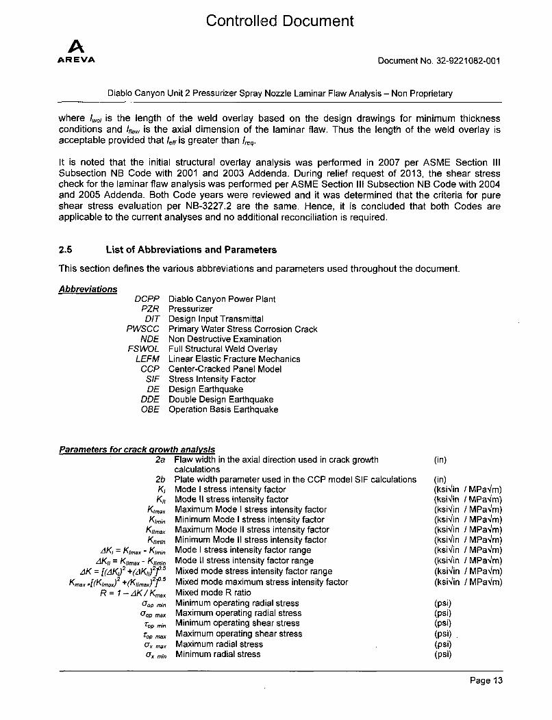
2.5 List of Abbreviations and Parameters
This section defines the various abbreviations and parameters used throughout the document.
AbbreviationsDCPP Diablo Canyon Power Plant
PZR PressurizerDIT Design Input Transmittal
PWSCC Primary Water Stress Corrosion CrackNDE Non Destructive Examination
FSWOL Full Structural Weld OverlayLEFM Linear Elastic Fracture Mechanics
CCP Center-Cracked Panel ModelSIF Stress Intensity FactorDE Design Earthquake
DDE Double Design EarthquakeOBE Operation Basis Earthquake
Parameters for crack growth analysis2a Flaw width in the axial direction used in crack growth (in)
calculations2b Plate width parameter used in the CCP model SIF calculations (in)K, Mode I stress intensity factor (ksi1in / MPa~m)K,, Mode II stress intensity factor (ksi'lin / MPa4m)
Kimax Maximum Mode I stress intensity factor (ksi•/in / MPa'4m)Kimn~ Minimum Mode I stress intensity factor (ksi'/in / MPaqm)
K,,max Maximum Mode II stress intensity factor (ksi'in / MPaqm)Kiimin Minimum Mode II stress intensity factor (ksiqin / MPa/m)
AK, = Kirax - Kimin Mode I stress intensity factor range (ksii/in / MPa/m)/AK, = Kimax - Kiimin Mode II stress intensity factor range (ksibin I MPa'/m)
AK [(AK,) 2 +(.K,0)2] 5 Mixed mode stress intensity factor range (ksiiin / MPaqm)Kmax =[(Kimax) 2 +(Kima)j 2f 5 Mixed mode maximum stress intensity factor (ksi1in / MPa~m)
R = I -AK/Kmax Mixed mode R ratiom•om mi, Minimum operating radial stress (psi)
uop max Maximum operating radial stress (psi)rop m•n Minimum operating shear stress (psi)
,op max Maximum operating shear stress (psi)Ox max Maximum radial stress (psi)
mor, mn Minimum radial stress (psi)
Page 13
Controlled Document
AAR EVA Document No. 32-9221082-001
Diablo Canyon Unit 2 Pressurizer Spray Nozzle Laminar Flaw Analysis - Non Proprietary
a,3 Residual radial stress (psi)z,• Residual shear stress (psi)
0*max Maximum radial stress (psi)rmmn Minimum radial stress (psi)
,rmax Maximum shear stress (psi),min Minimum shear stress (psi)
2ai Initial flaw width (in)2af Final flaw width (in)
2,Aa Flaw growth increment (in)
AN Number of cycles per year for a given transient in one direction (cycle/year)
Parameters used in indication area evaluationA Laminar indication area evaluation (in2)
w Flaw width used in the indication area evaluation (in)/ Flaw length used in the indication area evaluation (in)
Parameters for crack growth rate equationsda/dN Crack growth rate (in/cycle)
n Crack growth equation exponentT Temperature ('F or 'C)
CA600,C, Co, S, SR Coefficient in the crack growth equationsR R ratio
Parameters for required overlay length evaluationAnet Cross-sectional area of the weld overlay (in2)Znet Section modulus of the weld overlay (in3)
o~eI Tensile stress is calculated based on the net section properties (psi)with faulted moment
',eq Required overlay length to transfer the load through shear back to (in)the base metal
leff Effective length of the weld overlay (in)Iwo, Length of the weld overlay based on the design drawing (in)'fla, Axial dimension of the laminar flaw used in required overlay (in)
length assessmentOD Outer diameter (in)
D Diameter (same as outer diameter) (in)t Thickness (weld overlay) (in)
F Axial load (lbf)M Bending Moment (in-lbf)
Page 14
Controlled Document
AAR EVA Document No. 32-9221082-001
Diablo Canyon Unit 2 Pressurizer Spray Nozzle Laminar Flaw Analysis - Non Proprietary
3.0 ASSUMPTIONS
This section discusses the assumptions and modeling simplifications used in this document.
3.1 Unverified Assumptions
There are no assumptions that must be verified before the present analysis can be used to support thedisposition of the Diablo Canyon Unit 2 PZR Spray nozzle laminar indications.
3.2 Justified Assumptions
1. For the case where the R ratio < 0 (or similarly Kmin < 0), the R ratio is set equal to zero and thefull range of AK is used in the crack growth calculations. This is a conservative assumptionsince crack closure due to compressive stress field is ignored.
2. The analysis assumed 3600 laminar flaw for axial fatigue crack growth calculations, which is aconservative assumption since the full circumference was assumed cracked.
3. Final circumferential flaw length was estimated by extending the flaw length in proportion to theratio of the final flaw width to initial flaw width. This is a conservative assumption since flawgrowth in the circumferential (length) direction is expected to be less than the flaw growth in theaxial (width) direction.
3.3 Modeling Simplifications
1. Multiple laminar flaws in Reference [1] are combined into larger, bounding flaws and extendedto include a complete 3600 arc length for crack growth calculations. Conservatively, CCP modelis used to represent the 360' laminar flaws.
2. The mode I and mode II were combined using the square root summation of squares (SRSS).This results in a more conservative crack growth estimation than the linear summation of theindividual crack growth increments due mode I and mode II when the crack growth lawexponent is equal to or greater than 2 (i.e. for crack growth law proportional to AKn, when n isequal to or greater than 2, combining mode I and Mode II using the SRSS method results in aconservative estimation of the crack growth increment).
3. The 2b parameter for analyzing indications 1 and 4 was defined as the distance between thepoint where the overlay meets the nozzle and the butter. This is a conservative value forestimating the SIF since it is much smaller than the distance between the indication and the freesurfaces of the nozzle and the overlay.
4. The 2b parameter for analyzing indications 2 and 3 was defined as twice the distance betweenthe center of the SS Weld and the point at which the design reflects the structural thickness at(0.75[r t]112) from the toe of the weld where r is the outside radius and t is the nominal thickness.This is a conservative value for estimating the SIF since it is much smaller than the distancebetween the indication and the free surfaces of the nozzle and the overlay.
5. Contribution of the external loads to the fatigue crack growth of the laminar flaws analyzed inthe current document was assumed to be negligible. This is an engineering judgment since thesustained external loads will have minimal contributions to the cyclical radial and shear stresscomponents.
Page 15
AAREVA
Controlled Document
Document No. 32-9221082-001
Diablo Canyon Unit 2 Pressurizer Spray Nozzle Laminar Flaw Analysis - Non Proprietary
4.0 DESIGN INPUTS
4.1 Geometry
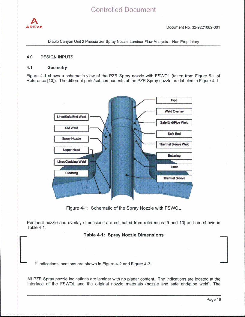
Figure 4-1 shows a schematic view of the PZR Spray nozzle with FSWOL (taken from Figure 5-1 ofReference [13]). The different parts/subcomponents of the PZR Spray nozzle are labeled in Figure 4-1.
Figure 4-1: Schematic of the Spray Nozzle with FSWOL
Pertinent nozzle and overlay dimensions are estimated from references [9 and 10] and are shown inTable 4-1.
Table 4-1: Spray Nozzle Dimensions
L I(1'Indications locations are shown in Figure 4-2 and Figure 4-3.
All PZR Spray nozzle indications are laminar with no planar content. The indications are located at theinterface of the FSWOL and the original nozzle materials (nozzle and safe end/pipe weld). The
Page 16
Controlled Document
AAREVA Document No. 32-9221082-001
Diablo Canyon Unit 2 Pressurizer Spray Nozzle Laminar Flaw Analysis - Non Proprietary
indications detected in the PZR Spray nozzle are shown on Figure 4-2 and Figure 4-3, and withadditional information provided in the Indication Data Sheet "WIB-345 OL Spray Nozzle" (Reference[1]). Detailed dimensions of the Spray nozzle are in Reference [9].
Figure 4-2: WIB-345 Overlay Rollout Spray Nozzle (Ref. [1])
Figure 4-3: Spray Nozzle WIB-345 Overlay Indication Plot (Ref. [1])
Page 17
Controlled Document
AAR EVA Document No. 32-9221082-001
Diablo Canyon Unit 2 Pressurizer Spray Nozzle Laminar Flaw Analysis - Non Proprietary
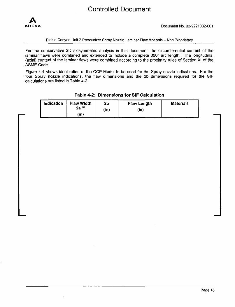
For the conservative 2D axisymmetric analysis in this document, the circumferential content of thelaminar flaws were combined and extended to include a complete 3600 arc length. The longitudinal(axial) content of the laminar flaws were combined according to the proximity rules of Section XI of theASME Code.
Figure 4-4 shows idealization of the CCP Model to be used for the Spray nozzle indications. For thefour Spray nozzle indications, the flaw dimensions and the 2b dimensions required for the SIFcalculations are listed in Table 4-2.
Table 4-2: Dimensions for SIF Calculation
Page 18

AAR EVA
Controlled Document
Document No. 32-9221082-001
Diablo Canyon Unit 2 Pressurizer Spray Nozzle Laminar Flaw Analysis - Non Proprietary
r
I
la:alb +"
G
Notes:
Figure 4-4: Idealization of the CCP Model for the Spray Nozzle Indications
Page 19
AAR EVA
Controlled Document
Document No. 32-9221082-001
Diablo Canyon Unit 2 Pressurizer Spray Nozzle Laminar Flaw Analysis - Non Proprietary
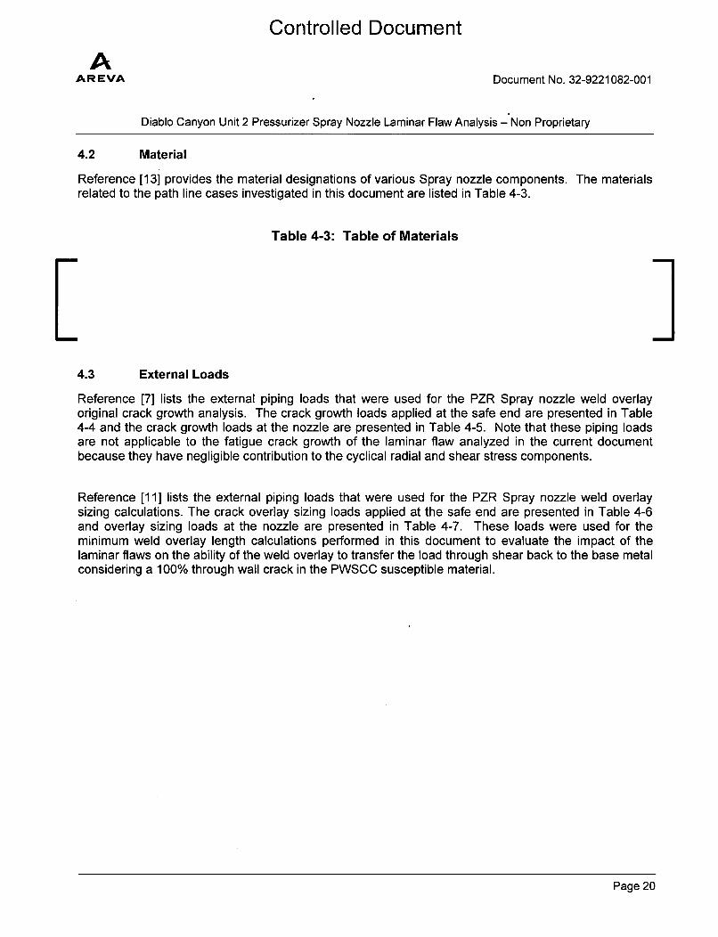
4.2 Material
Reference [13] provides the material designations of various Spray nozzle components. The materialsrelated to the path line cases investigated in this document are listed in Table 4-3.
Table 4-3: Table of Materials
L Ii4.3 External Loads
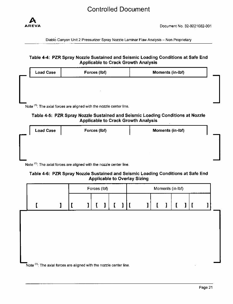
Reference [7] lists the external piping loads that were used for the PZR Spray nozzle weld overlayoriginal crack growth analysis. The crack growth loads applied at the safe end are presented in Table4-4 and the crack growth loads at the nozzle are presented in Table 4-5. Note that these piping loadsare not applicable to the fatigue crack growth of the laminar flaw analyzed in the current documentbecause they have negligible contribution to the cyclical radial and shear stress components.
Reference [11] lists the external piping loads that were used for the PZR Spray nozzle weld overlaysizing calculations. The crack overlay sizing loads applied at the safe end are presented in Table 4-6and overlay sizing loads at the nozzle are presented in Table 4-7. These loads were used for theminimum weld overlay length calculations performed in this document to evaluate the impact of thelaminar flaws on the ability of the weld overlay to transfer the load through shear back to the base metalconsidering a 100% through wall crack in the PWSCC susceptible material.
Page 20
AAR EVA
Controlled Document
Document No. 32-9221082-001
Diablo Canyon Unit 2 Pressurizer Spray Nozzle Laminar Flaw Analysis - Non Proprietary
Table 4-4: PZR Spray Nozzle Sustained and Seismic Loading Conditions at Safe EndApplicable to Crack Growth Analysis
Load Case Forces (Ibf) Moments (in-lbf)
Note (1): The axial forces are aligned with the nozzle center line.
Table 4-5: PZR Spray Nozzle Sustained and Seismic Loading Conditions at NozzleApplicable to Crack Growth Analysis
I
LLoad Case Forces (Ibf) Moments (in-lbf) IINote (1): The axial forces are aligned with the nozzle center line.
Table 4-6: PZR Spray Nozzle Sustained and Seismic Loading Conditions at Safe EndApplicable to Overlay Sizing
YI
Forces (lbf) Moments (in-lbf)
1 3 I cIIII I I I I 1 ] C
Note (1): The axial forces are aligned with the nozzle center line.
Page 21
AAR EVA
Controlled Document
Document No. 32-9221082-001
Diablo Canyon Unit 2 Pressurizer Spray Nozzle Laminar Flaw Analysis - Non Proprietary
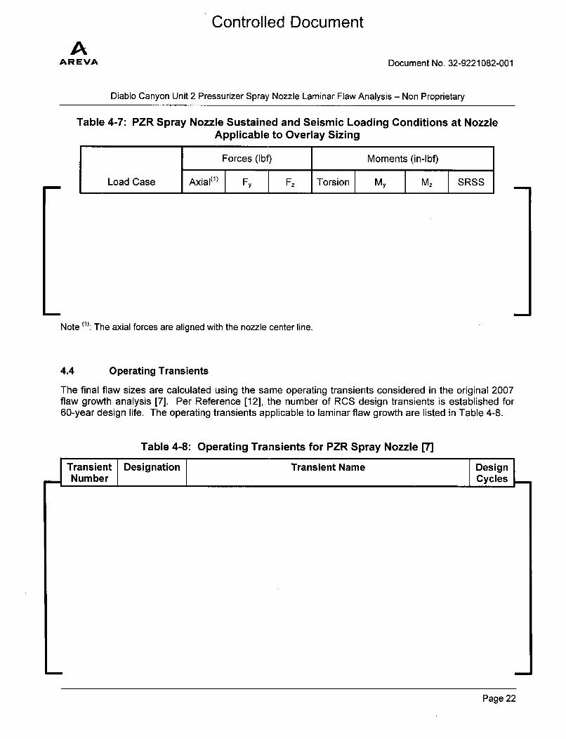
Table 4-7: PZR Spray Nozzle Sustained and Seismic Loading Conditions at NozzleApplicable to Overlay Sizing
Note (1): The axial forces are aligned with the nozzle center line.
4.4 Operating Transients
The final flaw sizes are calculated using the same operating transients considered in the original 2007flaw growth analysis [7]. Per Reference [12], the number of RCS design transients is established for60-year design life. The operating transients applicable to laminar flaw growth are listed in Table 4-8.
Table 4-8: Operating Transients for PZR Spray Nozzle [7]
I Transient DesignationNumberTransient Name Design I
Cycles
Page 22
Controlled Document
AAR EVA Document No. 32-9221082-001
Diablo Canyon Unit 2 Pressurizer Spray Nozzle Laminar Flaw Analysis - Non Proprietary
Transient Designation Transient Name DesignNumber Cycles~
Notes:
(1)Seismic loading is part of the upset loading conditions. It is not expected to contribute tothe radial and shear stress components, which constitute the crack driving force for laminarflaw. Thus, Seismic loading is not considered in fatigue crack growth of laminar flaws.
4.5 Operating Stresses
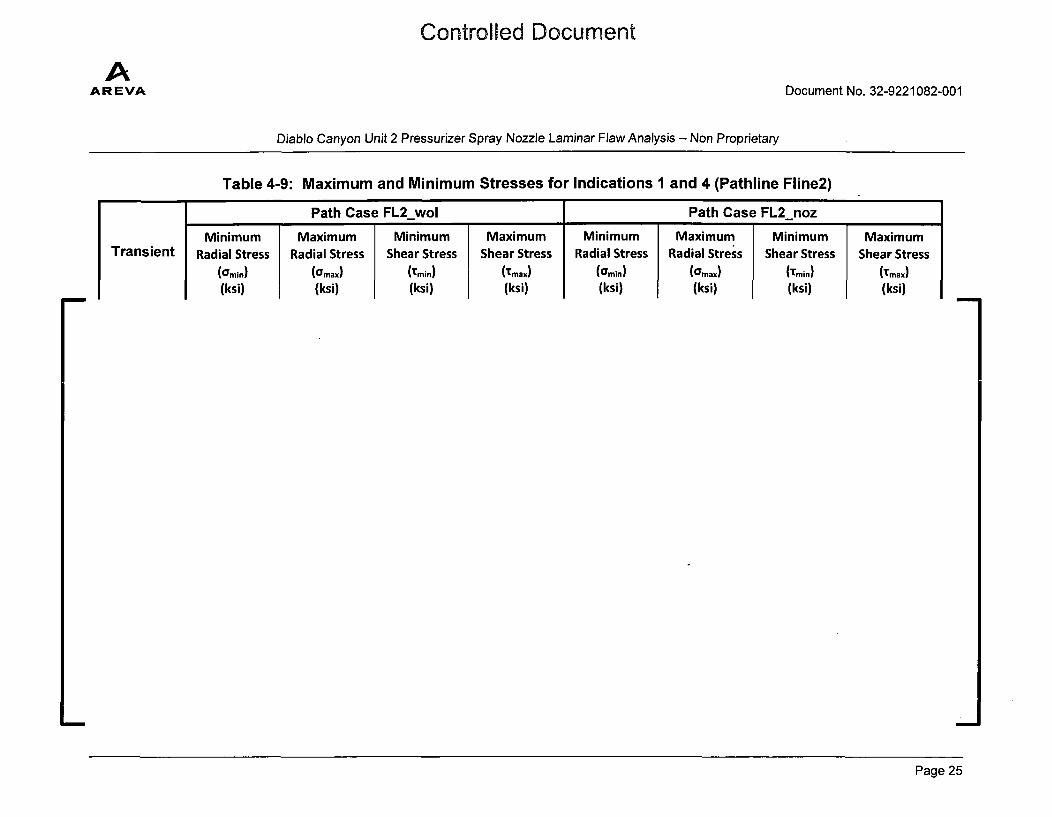
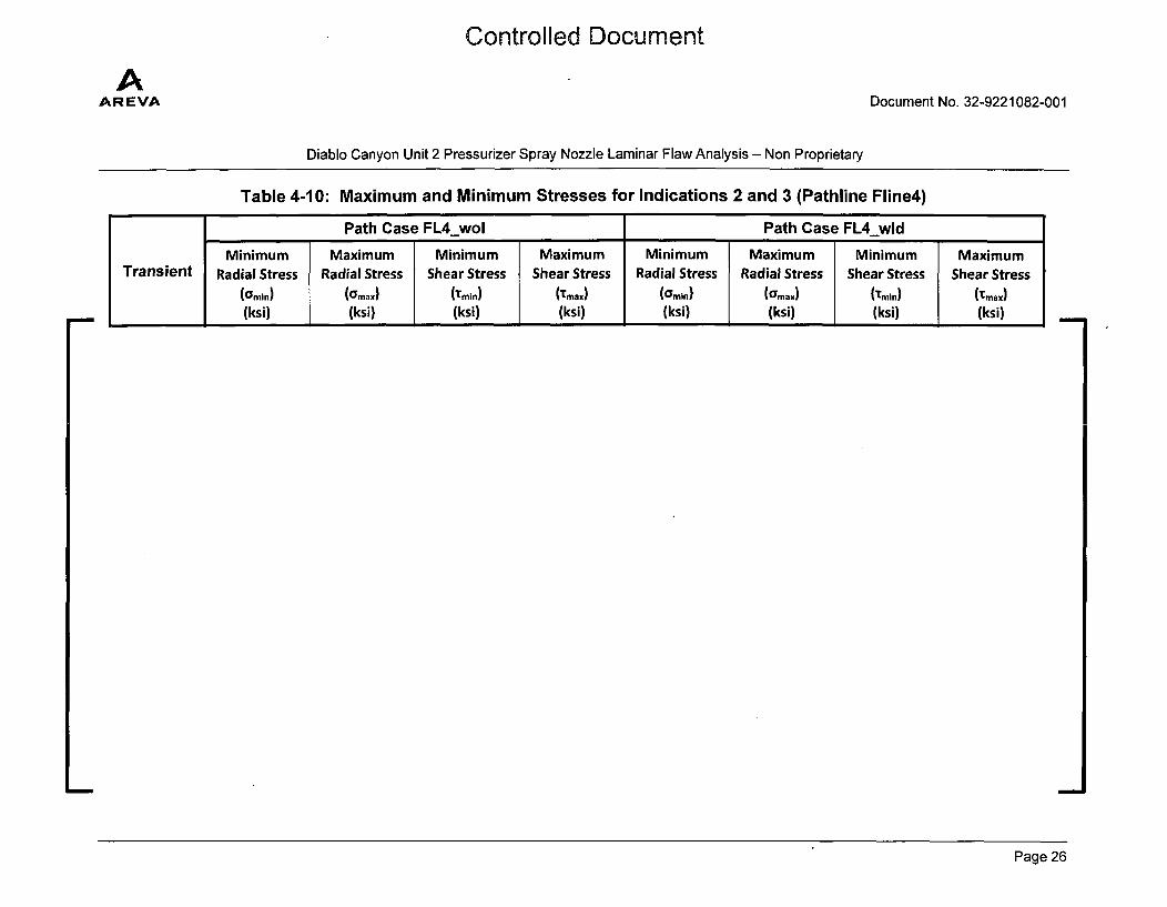
The cyclic operating stresses needed to calculate fatigue crack growth were obtained from a thermoelastic three-dimensional finite element analysis [13]. These fatigue stresses were developed for eachof the transients at a number of time points to capture the maximum and minimum stresses due tofluctuations in pressure and temperature. The stresses that are required for crack growth analysis forthe flaws are extracted in Appendix B of Reference [13]. Radial stresses contributing to Mode I crackgrowth are from files "SX". Shear stresses contributing to Mode II crack growth are from files "Sh".Since the SIF solutions in Section 2.1 are based on uniform stress, the stress data from Appendix B ofReference [13] were sorted to obtain maximum and minimum stresses along the path. Thesemaximum and minimum stresses are conservatively used as the stress values for SIF calculation. Inaddition, the stress data were further sorted based on time points in each transient. The maximum andminimum stresses for all time points in each transient for the each path line case are tabulated in Table4-9 through Table 4-10.
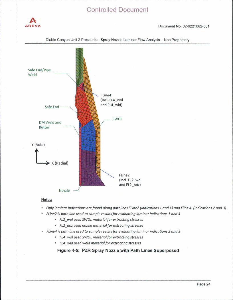
Reference [13] provided one set of results (stresses and temperatures) for analyzing indications #1 and#4 along pathline FLine2, as shown in Figure 4-5. Similarly, Reference [13] provided another set ofresults for analyzing indications #2 and #3 along pathline FLine4, as shown in Figure 4-5.
Since the indications in Figure 4-3 are located at the interfaces of different materials, it is not knownwhich material the crack will grow into. Therefore, two cases were investigated for each pathline basedon the two materials involved. Reference [13] defines two pathline cases, FL2_wol and FL2_noz forFLine2; the stresses for FL2_wol were extracted by selecting FSWOL material only and the stresses forFL2_noz were extracted by selecting nozzle material only. Similarly, for pathline FLine4 cases FL4_woland FL4_wld were defined by selecting FSWOL material and weld material, respectively. Thisdocument calculates fatigue crack growths on these four cases.
Page 23
AAREVA
Controlled Document
Document No. 32-9221082-001
Diablo Canyon Unit 2 Pressurizer Spray Nozzle Laminar Flaw Analysis - Non Proprietary
Safe End/PipeWeld
Safe End-
DM Weld andButter
FLine4(incl. FL4_woland FL4_wld)
-- SWOL
Y (Axial)
I 0, X (Radial)
FLine2(ind. FL2_woland FL2_noz)
Nozzle
Notes:
" Only laminar indications are found along pathlines FLine2 (indications 1 and 4) and Fline 4 (indications 2 and 3)." FLine2 is path line used to sample results for evaluating laminar indications 1 and 4
" FL2_wol used SWOL materialfor extracting stresses
" FL2_noz used nozzle materialfor extracting stresses
• FLine4 is path line used to sample results for evaluating laminar indications 2 and 3
" FL4_wol used SWOL materialfor extracting stresses
• FL4_wld used weld materialfor extracting stresses
Figure 4-5: PZR Spray Nozzle with Path Lines Superposed
Page 24
Controlled Document
AAR EVA Document No. 32-9221082-001
Diablo Canyon Unit 2 Pressurizer Spray Nozzle Laminar Flaw Analysis - Non Proprietary
Table 4-9: Maximum and Minimum Stresses for Indications 1 and 4 (Pathline Fline2)Y
Path Case FL2_wol Path Case FL2_noz*
TransientMinimum
Radial Stress(Gmin)
(ksi)
MaximumRadial Stress
(O'max)
(ksi)
MinimumShear Stress
(Tmin)
(ksi)
MaximumShear Stress
('max)
(ksi)
MinimumRadial Stress
(Cmin(ksi)
MaximumRadial Stress
(O'max)
(ksi)
MinimumShear Stress
(Tmin)
(ksi)
MaximumShear Stress
(Tmax)
(ksi)
Page 25
Controlled Document
AAR EVA Document No. 32-9221082-001
Diablo Canyon Unit 2 Pressurizer Spray Nozzle Laminar Flaw Analysis - Non Proprietary
Table 4-10: Maximum and Minimum Stresses for Indications 2 and 3 (Pathline Fline4)
Path Case FL4_wol Path Case FL4_wld
Minimum Maximum Minimum Maximum Minimum Maximum Minimum MaximumTransient Radial Stress Radial Stress Shear Stress Shear Stress Radial Stress Radial Stress Shear Stress Shear Stress
(Omin) (OYmax) (Tmin) (Tmax) (Gmin) (Omax) (tmin) (Tmax)
(ksi) (ksi) (ksi) (ksi) (ksi) (ksi) (ksi) (ksi)
Page 26
AAR EVA
Controlled Document
Document No. 32-9221082-001
Diablo Canyon Unit 2 Pressurizer Spray Nozzle Laminar Flaw Analysis - Non Proprietary
4.6 Operating Temperatures
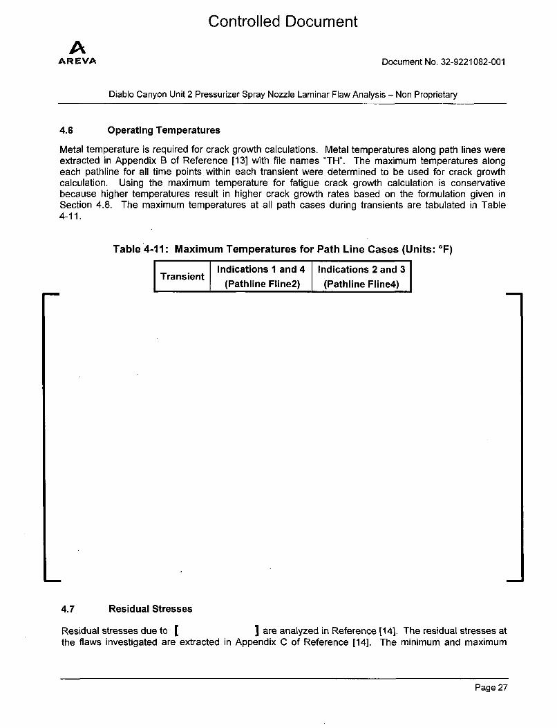
Metal temperature is required for crack growth calculations. Metal temperatures along path lines wereextracted in Appendix B of Reference [13] with file names "TH". The maximum temperatures alongeach pathline for all time points within each transient were determined to be used for crack growthcalculation. Using the maximum temperature for fatigue crack growth calculation is conservativebecause higher temperatures result in higher crack growth rates based on the formulation given inSection 4.8. The maximum temperatures at all path cases during transients are tabulated in Table4-11.
Table 4-11: Maximum Temperatures for Path Line Cases (Units: OF)
I i Indications 1 and 4 Indications 2 and 3Ti(Pathline Fline2) (Pathline Fline4)
4.7 Residual Stresses
Residual stresses due to [ I are analyzed in Reference [14]. The residual stresses atthe flaws investigated are extracted in Appendix C of Reference [14]. The minimum and maximum
Page 27
AAR EVA
Controlled Document
Document No. 32-9221082-001
Diablo Canyon Unit 2 Pressurizer Spray Nozzle Laminar Flaw Analysis - Non Proprietary
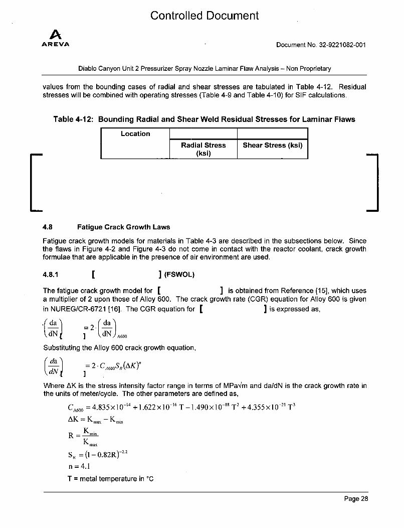
values from the bounding cases of radial and shear stresses are tabulated in Table 4-12. Residualstresses will be combined with operating stresses (Table 4-9 and Table 4-10) for SIF calculations.
Table 4-12: Bounding Radial and Shear Weld Residual Stresses for Laminar Flaws
4.8 Fatigue Crack Growth Laws
Fatigue crack growth models for materials in Table 4-3 are described in the subsections below. Sincethe flaws in Figure 4-2 and Figure 4-3 do not come in contact with the reactor coolant, crack growthformulae that are applicable in the presence of air environment are used.
4.8.1 ] (FSWOL)
The fatigue crack growth model for [ ] is obtained from Reference (15], which usesa multiplier of 2 upon those of Alloy 600. The crack growth rate (CGR) equation for Alloy 600 is givenin NUREG/CR-6721 [16]. The CGR equation for [ ] is expressed as,
.(da )r . da-dN dN) A600
Substituting the Alloy 600 crack growth equation,
Where AK is the stress intensity factor range in terms of MPa'lm and da/dN is the crack growth rate in
the units of meter/cycle. The other parameters are defined as,
CA60 0 = 4.835 X 10- 14 + 1.622 x 10⁻¹⁶ T - 1.490 x 10⁻¹⁸ T2 + 4.355 x 10-'1 T3
AK = K ma - Kmin
R - K minK max
SR = (1 - 0.82R)-22
n =4.1
T = metal temperature in °C
Page 28
Controlled Document
AAR EVA Document No. 32-9221082-001
Diablo Canyon Unit 2 Pressurizer Spray Nozzle Laminar Flaw Analysis - Non Proprietary
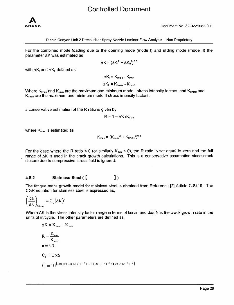
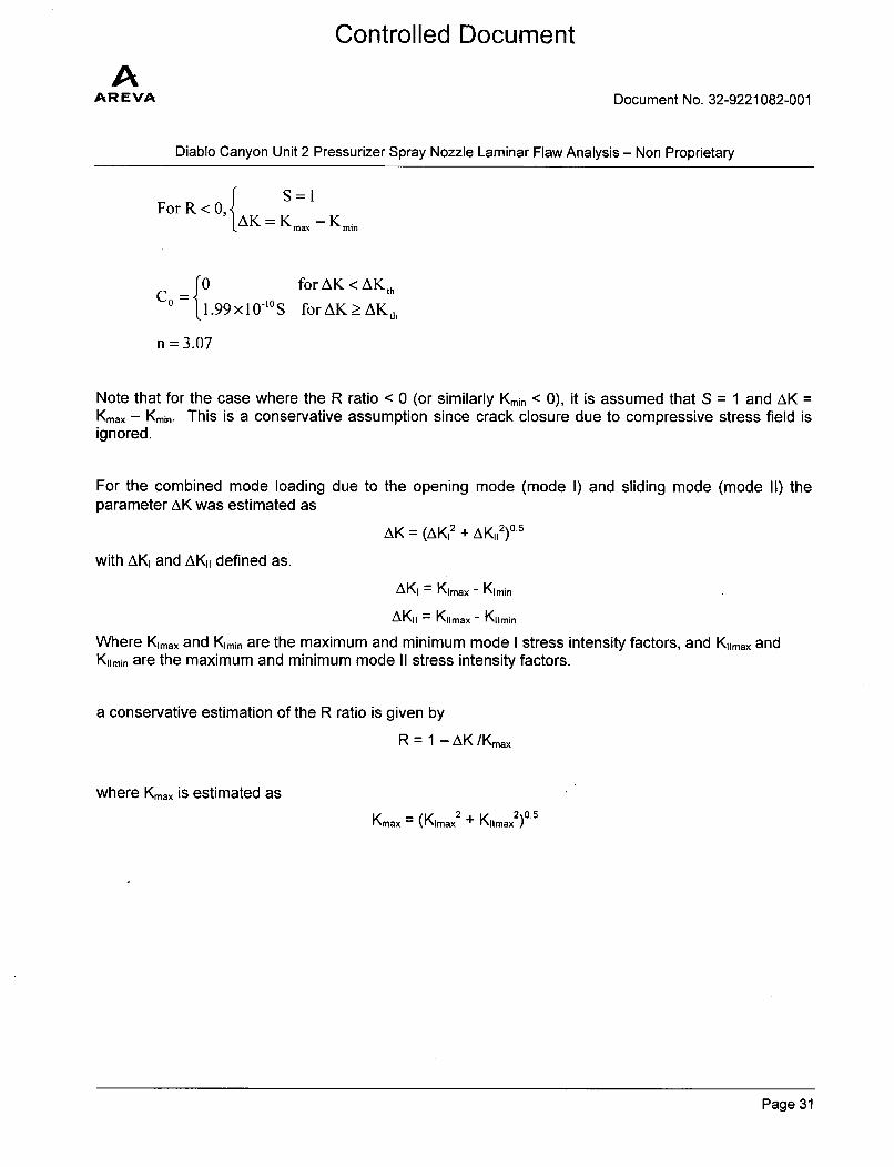
For the combined mode loading due to the opening mode (mode I) and sliding mode (mode II) theparameter AK was estimated as
AK = (AK12 + AK112)05
with AKI and AKI1 defined as.
AKI = Kimax - Kimin
AKII = KiImax - Kiimin
Where Kimax and Kimin are the maximum and minimum mode I stress intensity factors, and Kiimax andKrimin are the maximum and minimum mode II stress intensity factors.
a conservative estimation of the R ratio is given by
R = 1 - AK/Kmax
where Kmax is estimated as
Kmax = (KImax 2 + KIlimax=)°
For the case where the R ratio < 0 (or similarly Kmin < 0), the R ratio is set equal to zero and the fullrange of AK is used in the crack growth calculations. This is a conservative assumption since crackclosure due to compressive stress field is ignored.
4.8.2 Stainless Steel ( [ I)The fatigue crack growth model for stainless steel is obtained from Reference [2] Article C-8410. TheCGR equation for stainless steel is expressed as,
CdadN ) S-air
= Co(AK)n
Where AK is the stress intensity factor range in terms of ksi1in and da/dN is the crack growth rate in theunits of in/cycle. The other parameters are defined as,
AK = K.ma - Kmin
R- K.in
K max
n =3.3
CO =CxS
C = lO(10-009+8.12xi0-4T-1.13x10⁻⁶T2 +1.02x 10-T 3)
Page 29
Controlled Document
AAR EVA Document No. 32-9221082-001
Diablo Canyon Unit 2 Pressurizer Spray Nozzle Laminar Flaw Analysis - Non Proprietary
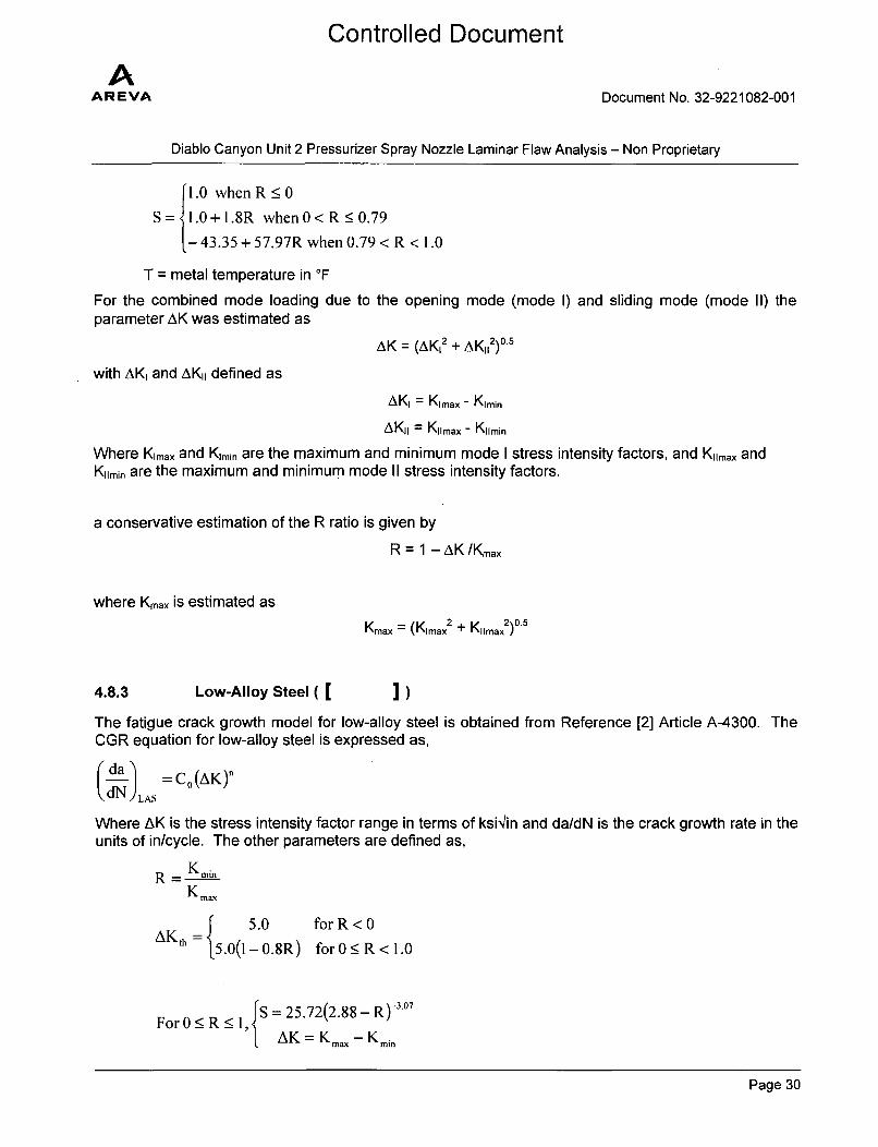
[1.0 when R •0S = 1.0 +1.8R when0<R<0.79
- 43.35 + 57.97R when 0.79 < R < 1.0
T = metal temperature in OF
For the combined mode loading due to the opening mode (mode I) and sliding mode (mode II) theparameter AK was estimated as
AK = (AK12 + AK112)05
with AKI and AKI, defined as
AKI = Kimax - Kimin
AKII = Kiimax - Kiimin
Where Krmax and Kimin are the maximum and minimum mode I stress intensity factors, and Kirmax andKrimin are the maximum and minimum mode II stress intensity factors.
a conservative estimation of the R ratio is given by
R = 1 - AK/Kmax
where Kmax is estimated as
Kmax = (Kimax 2 + Kiimax2)05
4.8.3 Low-Alloy Steel ( [ ] )The fatigue crack growth model for low-alloy steel is obtained from Reference [2] Article A-4300. The
CGR equation for low-alloy steel is expressed as,
C da =c 0(AK)ndN LAS
Where AK is the stress intensity factor range in terms of ksi'/in and da/dN is the crack growth rate in theunits of in/cycle. The other parameters are defined as,
R - KminK max
5.0 for R < 0AKth = 5.0(1-0.8R) forO0R<1.0
FS = 25.72(2.88- R) 3 °7For 0_ R <1,•AK = Kmax - K.mn
Page 30
Controlled Document
AAR EVA Document No. 32-9221082-001
Diablo Canyon Unit 2 Pressurizer Spray Nozzle Laminar Flaw Analysis - Non Proprietary
For R < 0, ýAK = Km••, - Kmin
C 0 for AK < AKhC 1.99x10-"OS forAK_>AKth
n = 3.07
Note that for the case where the R ratio < 0 (or similarly Kmin < 0), it is assumed that S = 1 and AK =Kmax - Kmin. This is a conservative assumption since crack closure due to compressive stress field isignored.
For the combined mode loading due to the opening mode (mode I) and sliding mode (mode II) theparameter AK was estimated as
AK = (AK12 + AK11
2)0°5
with AKI and AK,, defined as.
AKI = Kimax - Kimin
AKI = Kiimax - Kiimin
Where Kimax and Kimin are the maximum and minimum mode I stress intensity factors, and Kiimax andKiimin are the maximum and minimum mode II stress intensity factors.
a conservative estimation of the R ratio is given by
R = 1 - AK/Kmax
where Kmax is estimated as
Kmax = (Kimax 2 + K11max2 ) 0 5
Page 31
Controlled Document
AAR EVA Document No. 32-9221082-001
Diablo Canyon Unit 2 Pressurizer Spray Nozzle Laminar Flaw Analysis - Non Proprietary
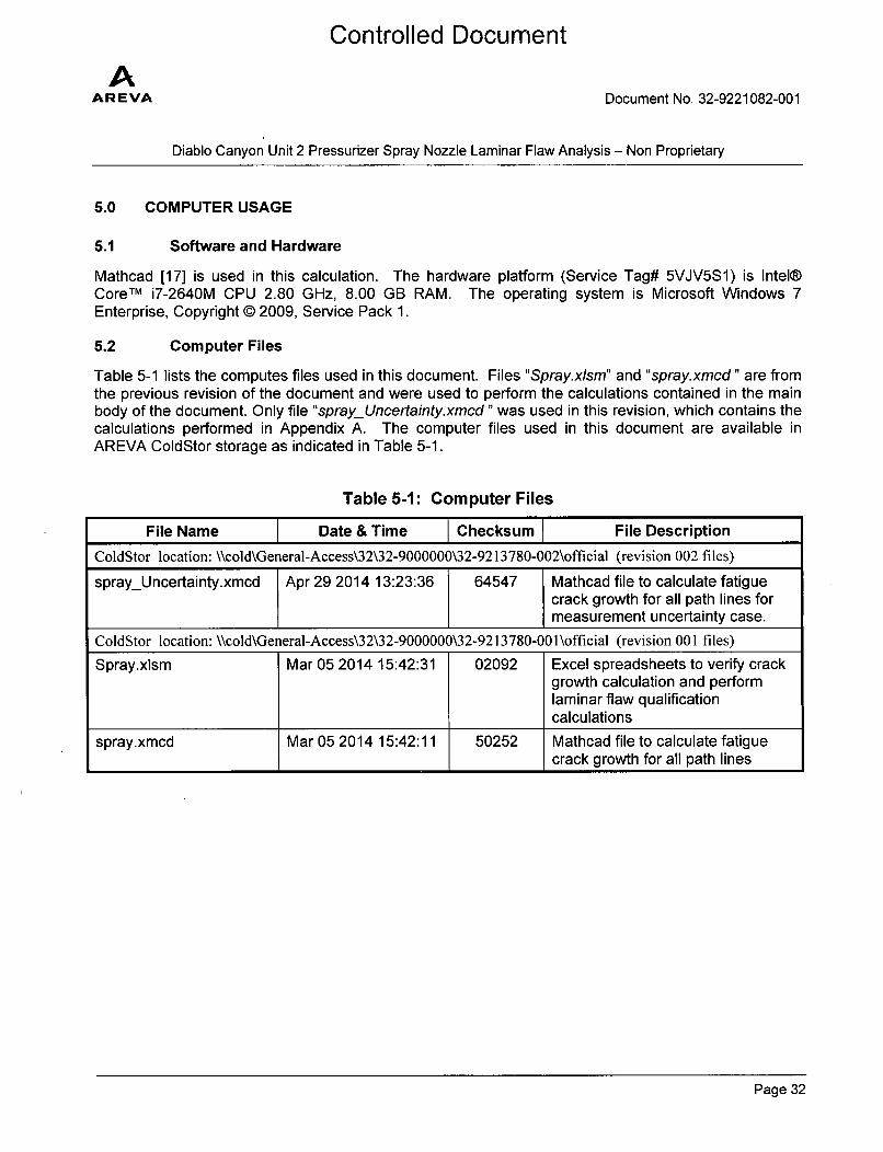
5.0 COMPUTER USAGE
5.1 Software and Hardware
Mathcad [17] is used in this calculation. The hardware platform (Service Tag# 5VJV5S1) is Intel®Core TM i7-2640M CPU 2.80 GHz, 8.00 GB RAM. The operating system is Microsoft Windows 7Enterprise, Copyright © 2009, Service Pack 1.
5.2 Computer Files
Table 5-1 lists the computes files used in this document. Files "Spray.xlsm" and "spray.xmcd" are fromthe previous revision of the document and were used to perform the calculations contained in the mainbody of the document. Only file "sprayUncertainty.xmcd" was used in this revision, which contains thecalculations performed in Appendix A. The computer files used in this document are available inAREVA ColdStor storage as indicated in Table 5-1.
Table 5-1: Computer Files
File Name Date & Time I Checksum I File Description
ColdStor location: \\cold\General-Access\32\32-9000000\32-9213 780-002\official (revision 002 files)
sprayUncertainty.xmcd Apr 29 2014 13:23:36 64547 Mathcad file to calculate fatiguecrack growth for all path lines formeasurement uncertainty case.
ColdStor location: \\cold\General-Access\32\32-9000000\32-9213780-001 \official (revision 001 files)
Spray.xlsm Mar 05 2014 15:42:31 02092 Excel spreadsheets to verify crackgrowth calculation and performlaminar flaw qualificationcalculations
spray.xmcd Mar 05 2014 15:42:11 50252 Mathcad file to calculate fatigueI_ I_ _crack growth for all path lines
Page 32
Controlled Document
AAR EVA Document No. 32-9221082-001
Diablo Canyon Unit 2 Pressurizer Spray Nozzle Laminar Flaw Analysis - Non Proprietary
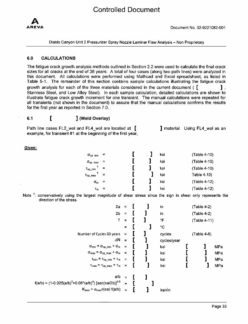
6.0 CALCULATIONS
The fatigue crack growth analysis methods outlined in Section 2.2 were used to calculate the final cracksizes for all cracks at the end of 38 years. A total of four cases (along two path lines) were analyzed inthis document. All calculations were performed using Mathcad and Excel spreadsheet, as listed inTable 5-1. The remainder of this section contains sample calculations illustrating the fatigue crackgrowth analysis for each of the three materials considered in the current document ( [ I IStainless Steel, and Low Alloy Steel). In each sample calculation, detailed calculations are shown toillustrate fatigue crack growth increment for one transient. The manual calculations were repeated forall transients (not shown in the document) to assure that the manual calculations confirms the resultsfor the first year as reported in Section 7.0.
6.1 [ ] (Weld Overlay)
Path line cases FL2_wol and FL4_wol are located at [example, for transient #1 at the beginning of the first year,
I material. Using FL4_wol as an
Given:
O'op min
Gop max -
Top_min -
Topmax =
"rs -
Note t: conservatively using the largest magnitude ofdirection of the stress.
[[[
I ksiksi
11 ksiksiksi
ksi
(Table 4-10)
(Table 4-10)
(Table 4-10)
Table 4-10)
(Table 4-12)
(Table 4-12)[
shear stress since the sign in shear only represents the
2a =
2b =
T =
I in
= [Number of Cycles 60 years
II
II
O'min = op_min +
0max = Gopmax +
Tmin = top_min -
tmax = Topmax -
] in
AN =
Ocrs = [Crs = [
+'Crs =
oF
cycles
cycles/yearksi
ksi]] ksi
ksi
[
[MPaMPa
]] MPa
MPa
(Table 4-2)
(Table 4-2)
(Table 4-11)
(Table 4-8)
a/b
f(a/b) = (1-0.025(a/b) 2+0. 06*(a/b) 4) [sec(ita/2b)]0 5
Kimin = (ymaxV(iTa) f(a/b)
[c[ I ksi'in
Page 33
AAR EVA
Controlled Document
Document No. 32-9221082-001
Diablo Canyon Unit 2 Pressurizer Spray Nozzle Laminar Flaw Analysis - Non Proprietary
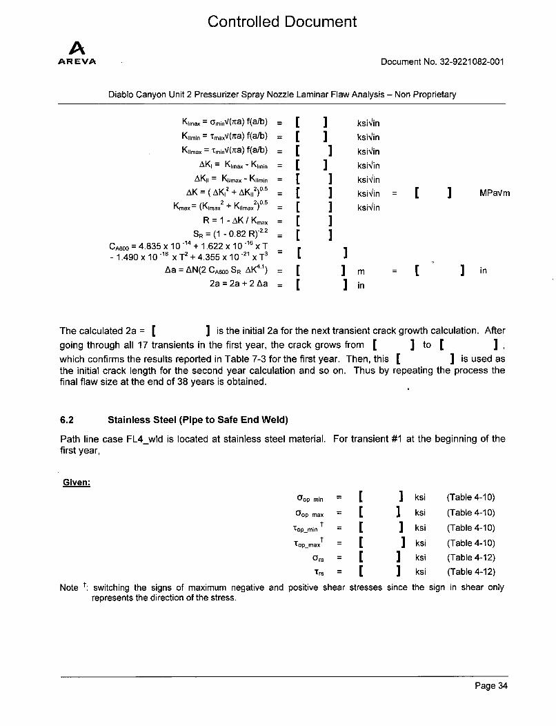
Kimax = GminV(ita) f(a/b)
Kiimin = 'maxV(ita) f(a/b)
Kiimax = :TminV(iTa) f(a/b)
AKI = Kimax - Kimin
AKII = K, max - Kiimin
AK = (AK 12 + AK 11
2) 0 5
Kmax = (Kimax2 + KjImax
2)0 5
R = 1 - AK / Kmax
SR = (1 - 0.82 R)-2.2
CA600 = 4.835 x 10 -14 + 1.622 x 10 -16 x T- 1.490 x 10 -18 x T2 + 4.355 x 10⁻²¹ x T3
Aa = AN(2 CA600 SR AK4 1)
2a = 2a + 2 Aa
CCCCCCCCCCCC
] ksi~inI ks~inI ksi~inI ksi'inI ksi'inI ksblinI ksi'in
MCaI
]] m
in
- C ] in
The calculated 2a = I ] is the initial 2a for the next transient crack growth calculation. Aftergoing through all 17 transients in the first year, the crack grows from Iwhich confirms the results reported in Table 7-3 for the first year. Then, thisthe initial crack length for the second year calculation and so on. Thus byfinal flaw size at the end of 38 years is obtained.
] to
repeating
I ] ,] is used as
the process the
6.2 Stainless Steel (Pipe to Safe End Weld)
Path line case FL4_wld is located at stainless steel material. For transient #1 at the beginning of thefirst year,
Given:
O'opmin = ] ksi (Table 4-10)
Oop max = ] ksi (Table 4-10)T
opmin 1 = ] ksi (Table 4-10)p-maxt =] ksi (Table 4-10)
ors =ksi (Table 4-12)Trs =] ksi (Table 4-12)
Note t: switching the signs of maximum negative and positive shear stresses since the sign in shear onlyrepresents the direction of the stress.
Page 34
AAREVA
Controlled Document
Document No. 32-9221082-001
Diablo Canyon Unit 2 Pressurizer Spray Nozzle Laminar Flaw Analysis - Non Proprietary
2a =
2b =
T =
Number of Cycles 60 years =
AN =
0'min = Oop-min + 0
rs =
Umax = 0
opmax + Crs =
tmin = top_min + Trs =
tmax = Top max + Tr =s
in
inOF
(Table 4-2)
(Table 4-2)
(Table 4-11)
(Table 4-8)
I cycles/yearksi
ksi
ksi
ksi
a/b
f(a/b) = (1-0.025(a/b) 2+0. 06*(a/b)4) [sec(nta/2b)]0 5
Kimin = OmaxV(ita) f(a/b)Kimax = OminV(ta) f(a/b)
Kiimin = tmaxV(iTa) f(a/b)Krmna, = TminV(ita) f(a/b)
AKI = Kimax - Kimin
AKII Kiimax - KIImin
AK = (AK'2 + AK,2)°5
Kmax = (Kimax2 + Kiimax
2 )O5
R = 1 - AK / Kmax
S (Section 4.8.2)
C = 10(-10.009 +8.12xO0-4T-1.13x10⁻⁶T 2 +1.02 x 10⁻⁹T 3)
Co = CS
Aa = AN(co AK3-3)
2a = 2a + 2 Aa
II
]I ksi'inI ksi~inI ksi'in:i ksi~inI ksr~inI ksi'inI ksh~inI ksi~in
II in
in
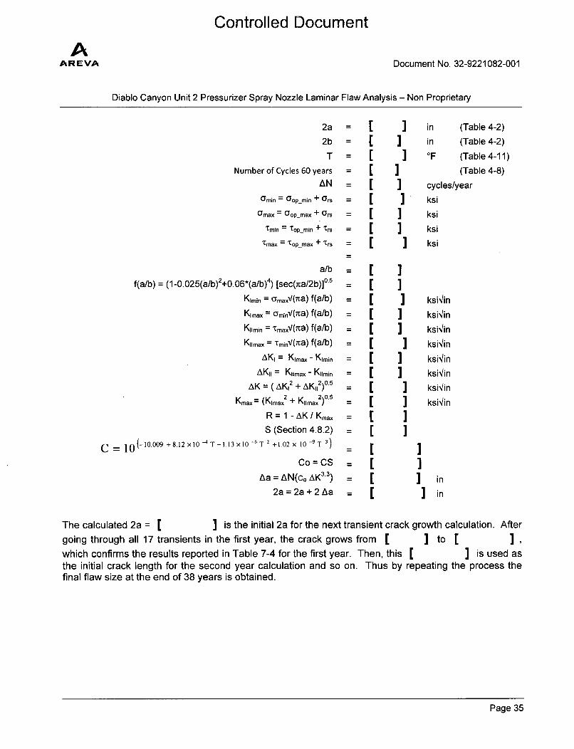
The calculated 2a = [ ] is the initial 2a for the next transient crack growth calculation. Aftergoing through all 17 transients in the first year, the crack grows from [ ] to [ I I
which confirms the results reported in Table 7-4 for the first year. Then, this [ ] is used asthe initial crack length for the second year calculation and so on. Thus by repeating the process thefinal flaw size at the end of 38 years is obtained.
Page 35
AAREVA
Controlled Document
Document No. 32-9221082-001
Diablo Canyon Unit 2 Pressurizer Spray Nozzle Laminar Flaw Analysis - Non Proprietary
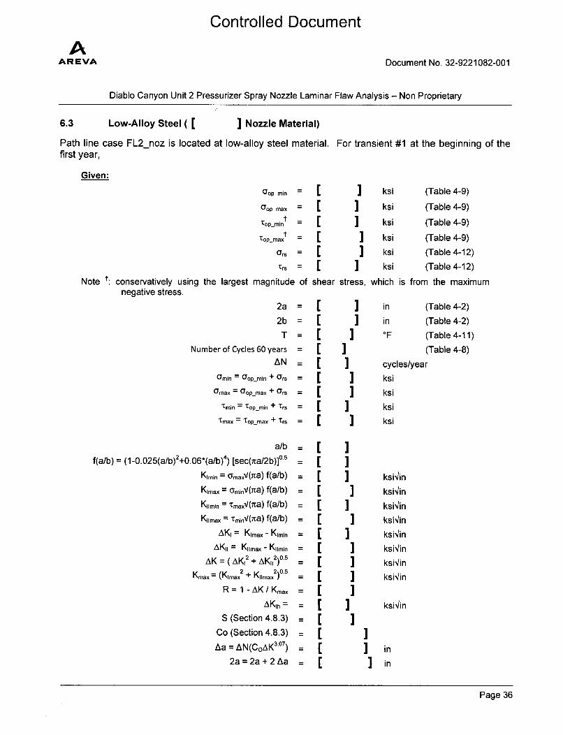
6.3 Low-Alloy Steel ( [ ] Nozzle Material)
Path line case FL2_noz is located at low-alloy steel material. For transient #1 at the beginning of thefirst year,
Given:
oop min = _
Oop max
Top-mint [[
Top max 1
ors C
]]]]
stress,
ksi
ksi
ksi
ksi
ksi
ksi
which
(Table 4-9)
(Table 4-9)
(Table 4-9)
(Table 4-9)
(Table 4-12)
(Table 4-12)
is from the maximum
Trs =
Note t: conservatively using the largest magnitude ofnegative stress.
L
shear
2a =
2b =
T =
Number of Cycles 60 years =
AN =
Omin = op-min + ors =
Umax = Oopmax + 0rs =
Tmin = Top-min + Trs =
Tmax = 'Top-max + 1Trs =
a/b
f(a/b) = (1-0.025(a/b)2+0.06*(a/b)4) [sec(ita/2b)]0 5
Kimin = GmaxV(ta) f(a/b)
Kim.x = aminV(iTa) f(a/b)
Kiimin = TmaxV(ia) f(a/b)
K1rmax = TminV(na) f(a/b)
AKi = Kimax - Klmin
AKI = Kiimax - KiImin
AK = (AK12 + AK11
2)0°5
Kmax= (Kimax2 + Kiimax
2)O'
R = 1 - AK / Kmax
AKth =
S (Section 4.8.3)
Co (Section 4.8.3)
Aa = AN(CoAK 30 7)
2a = 2a + 2 Aa
CCCCCCCCCCCCCCCC
I in (Table 4-2)in (Table 4-2)O 0F (Table 4-11)
(Table 4-8)
cycles/yearksi
ksi
]] ksiksi
]] ksi'4in
ksi/in
]] ksi/inksi'in
]] ksi'/in
ksi'inI ksi'4in
ksiin]] ksi'/in
]
Iinin
Page 36
Controlled Document
AAR EVA Document No. 32-9221082-001
Diablo Canyon Unit 2 Pressurizer Spray Nozzle Laminar Flaw Analysis - Non Proprietary
The calculated 2a = [ ] is the initial 2a for the next transient crack growth calculation. Aftergoing through all 17 transients in the first year, the crack grows from I I to [ I Iwhich confirms the results reported in Table 7-2 for the first year. Then, this to I ] is usedas the initial crack length for the second year calculation and so on. Thus by repeating the process thefinal flaw size at the end of 38 years is obtained.
7.0 RESULTS
7.1 Fatigue Crack Growth
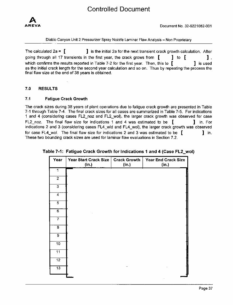
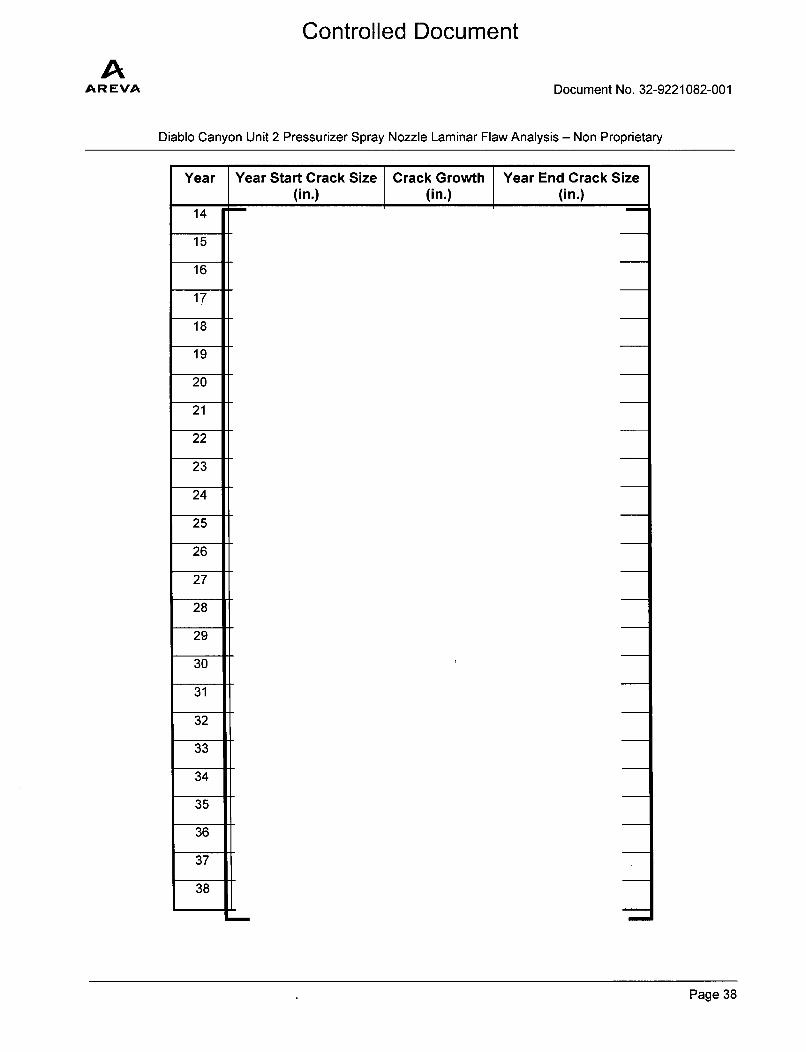
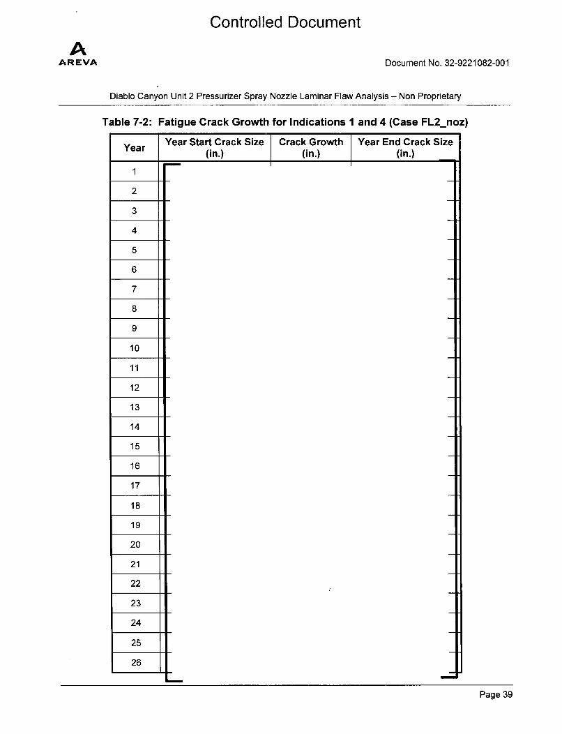
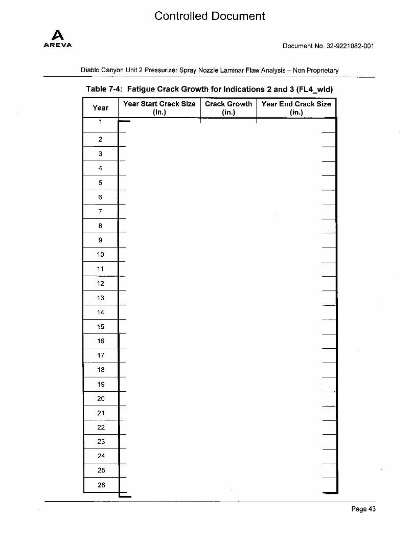
The crack sizes during 38 years of plant operations due to fatigue crack growth are presented in Table7-1 through Table 7-4. The final crack sizes for all cases are summarized in Table 7-5. For indications1 and 4 (considering cases FL2_noz and FL2 wol), the larger crack growth was observed for caseFL2_noz. The final flaw size for indications 1 and 4 was estimated to be I ] in. Forindications 2 and 3 (considering cases FL4_wld and FL4_wol), the larger crack growth was observedfor case FL4_wol. The final flaw size for indications 2 and 3 was estimated to be [ ] in.These two bounding crack sizes are used for laminar flaw evaluations in Section 7.2.
Table 7-1: Fatigue Crack Growth for Indications 1 and 4 (Case FL2_wol)
Year Year Start Crack Size Crack Growth Year End Crack Size(in.) (in.) (in.)
1
2
3
4
5
6
7
8
9
10
11
12
13
Page 37
AAREVA
Controlled Document
Document No. 32-9221082-001
Diablo Canyon Unit 2 Pressurizer Spray Nozzle Laminar Flaw Analysis - Non Proprietary
Year Year Start Crack Size Crack Growth Year End Crack Size(in.) (in.) (in.)
14
15
16
17
18
19
20
21
22
23
24
25
26
27
28
29
30
31
32
33
34
35
36
37
38
Page 38
AAR EVA
Controlled Document
Document No. 32-9221082-001
Diablo Canyon Unit 2 Pressurizer Spray Nozzle Laminar Flaw Analysis - Non Proprietary
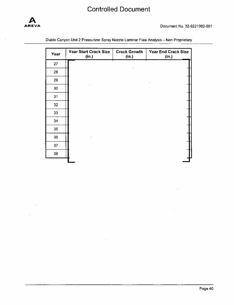
Table 7-2: Fatigue Crack Growth for Indications 1 and 4 (Case FL2_noz)
YearYear Start Crack Size Crack Growth Year End Crack Size
(in.) (in.) (in.)1
2
3
4
5
6
7
8
9
10
11
12
13
14
15
16
17
18
19
20
21
22
23
24
25
26
Page 39
AAREVA
Controlled Document
Document No. 32-9221082-001
Diablo Canyon Unit 2 Pressurizer Spray Nozzle Laminar Flaw Analysis - Non Proprietary
Year
27
28
29
30
31
32
33
34
35
36
37
38
Year Start Crack Size Crack Growth Year End Crack Size(in.) (in.) (in.)
Page 40

AAR EVA
Controlled Document
Document No. 32-9221082-001
Diablo Canyon Unit 2 Pressurizer Spray Nozzle Laminar Flaw Analysis - Non Proprietary
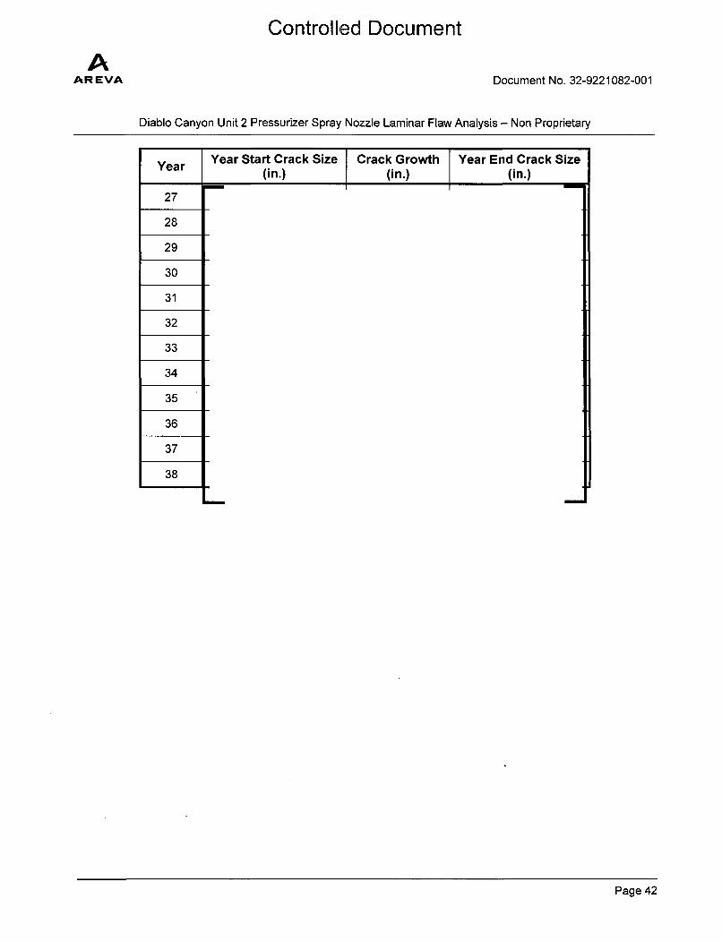
Table 7-3: Fatigue Crack Growth for Indications 2 and 3 (Case FL4_wol)
YearYear Start Crack Size Crack Growth Year End Crack Size
(in.) (in.) (in.)1
2
3
4
5
6
7
8
9
10
11
12
13
14
15
16
17
18
19
20
21
22
23
24
25
26
Page 41
AAR EVA
Controlled Document
Document No. 32-9221082-001
Diablo Canyon Unit 2 Pressurizer Spray Nozzle Laminar Flaw Analysis - Non Proprietary
YearYear Start Crack Size Crack Growth Year End Crack Size
(in.) (in.) (in.)
27
28
29
30
31
32
33
34
35
36
37
38
Page 42
Controlled Document
AAR EVA Document No. 32-9221082-001
Diablo Canyon Unit 2 Pressurizer Spray Nozzle Laminar Flaw Analysis - Non Proprietary
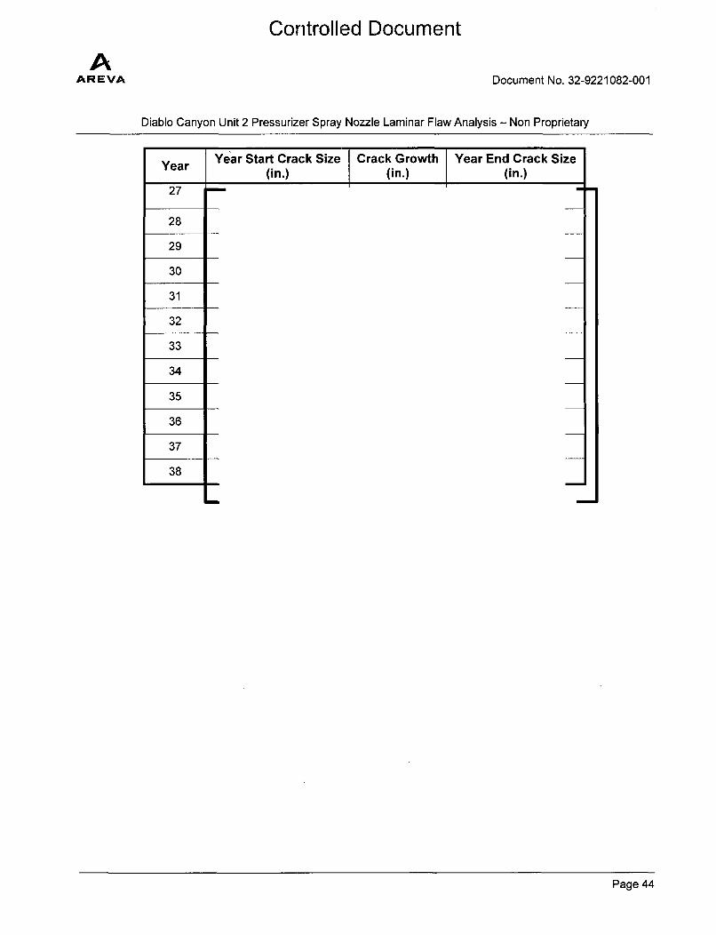
Table 7-4: Fatigue Crack Growth for Indications 2 and 3 (FL4_wld)Year Start Crack Size Crack Growth Year End Crack Size
(in.) (in.) (in.)
1
2
3
4
5
6
7
8
9
10
11
12
13
14
15
16
17
18
19
20
21
22
23
24
25
26
Page 43
AAREVA
Controlled Document
Document No. 32-9221082-001
Diablo Canyon Unit 2 Pressurizer Spray Nozzle Laminar Flaw Analysis - Non Proprietary
Year Start Crack Size Crack Growth Year End Crack Size(in.) (in.) (in.)
27
28
29
30
31
32
33
34
35
36
37
38
Page 44
AAR EVA
Controlled Document
Document No. 32-9221082-001
Diablo Canyon Unit 2 Pressurizer Spray Nozzle Laminar Flaw Analysis - Non Proprietary
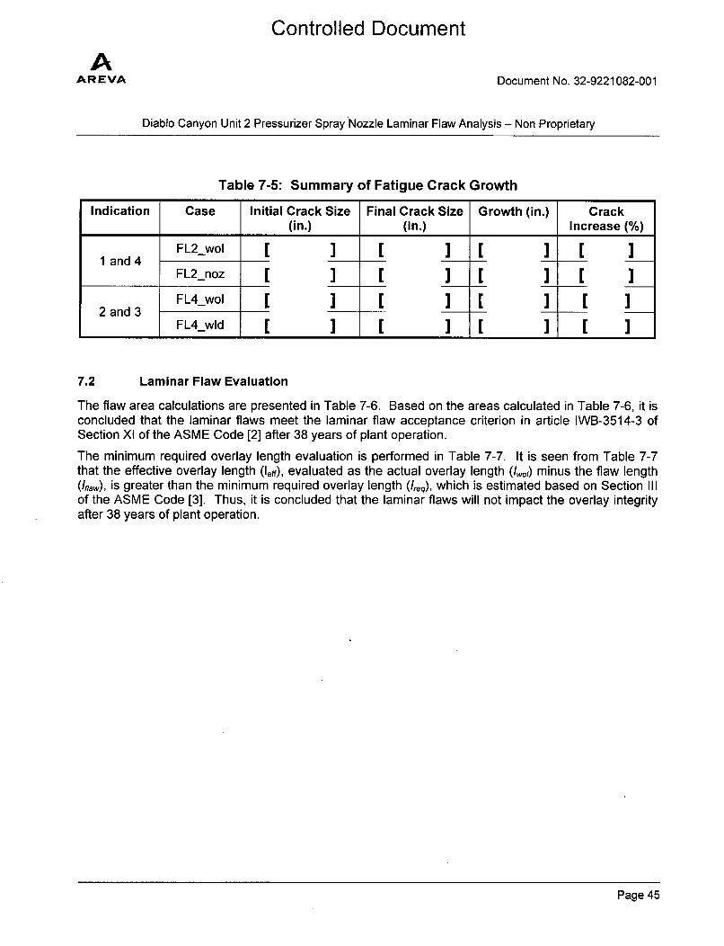
Table 7-5: Summary of Fatigue Crack Growth
Indication Case Initial Crack Size Final Crack Size Growth (in.) Crack(in.) (in.) Increase (%)
FL2_wol [ ] [ ] [ ] [ ]1 and 4
FL2noz [ ] [ ] [ ] [ ]FL4_wol [ ] [ ] [ ] [ ]
2 and 3
FL4_wld [ I [ I [ I [
7.2 Laminar Flaw Evaluation
The flaw area calculations are presented in Table 7-6. Based on the areas calculated in Table 7-6, it isconcluded that the laminar flaws meet the laminar flaw acceptance criterion in article IWB-3514-3 ofSection XI of the ASME Code [2] after 38 years of plant operation.
The minimum required overlay length evaluation is performed in Table 7-7. It is seen from Table 7-7that the effective overlay length (leO), evaluated as the actual overlay length (I,,o) minus the flaw length(iaw), is greater than the minimum required overlay length (Ireq), which is estimated based on Section IIIof the ASME Code [3]. Thus, it is concluded that the laminar flaws will not impact the overlay integrityafter 38 years of plant operation.
Page 45
AAR EVA
Controlled Document
Document No. 32-9221082-001
Diablo Canyon Unit 2 Pressurizer Spray Nozzle Laminar Flaw Analysis - Non Proprietary
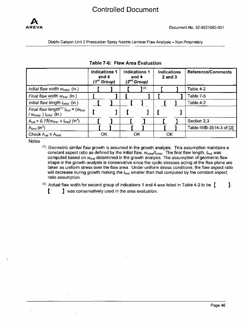
Table 7-6: Flaw Area Evaluation
Indications 1 Indications I Indications ReferencelCommentsand 4 and 4 2 and 3
(1st Group) (2nd Group)
Initial flaw width Winitial (in.) [ ] [ ](2) [ ] Table 4-2
Final flaw width Wnal (in.) [ ] [ ] [ ] Table 7-5
Initial flaw length 'initial (in.) [ ] [ ] [ ] Table 4-2
Final flaw length"1 ) 'final = (wfinalI Winitia, ) linitial (in.)( [] (]
A.a = 0. 75(Wfinal X Ifinad (in2 ) [ [ ] [ ] Section 2.3
Alimit (in2) ] Table IWB-3514-3 of [2]
Check Acai - Ariit OK OK OK
Notes(1): Geometric similar flaw growth is assumed in the growth analysis. This assumption maintains a
constant aspect ratio as defined by the initial flaw, Wiitiai/linitiai. The final flaw length, /final wascomputed based on Wfinai determined in the growth analysis. The assumption of geometric flawshape in the growth analysis is conservative since the cyclic stresses acting at the flaw plane aretaken as uniform stress over the flaw area. Under uniform stress conditions, the flaw aspect ratiowill decrease during growth making the /fina smaller than that computed by the constant aspectratio assumption.
(2): Actual flaw width for second group of indications 1 and 4 was listed in Table 4-2 to be "
I I was conservatively used in the area evaluation.I.
Page 46
AAR EVA
Controlled Document
Document No. 32-9221082-001
Diablo Canyon Unit 2 Pressurizer Spray Nozzle Laminar Flaw Analysis - Non Proprietary
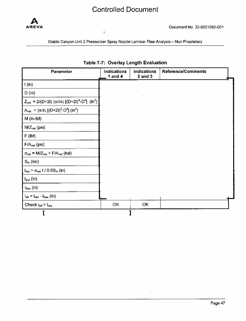
Table 7-7: Overlay Length Evaluation
Parameter Indications Indications Reference/CommentsI 1and 4 2 and 3 L
,ý- 1 and 4 2 and 3 "l
t (in)
D (in)
Znet = 2/(D+2t) (Ir/64) [(D+2t)4-D4] (in3)
Anet = (i/4) [(D+2t)2-D2] (in2)
M (in-lbf)
M/Znet (psi)
F (lbf)
F/Anet (psi)
(ynet = M/Znet + F/Anet (ksi)
Sm (ksi)
1req = anet t / 0.6Sm (in)
(n)
Iflaw (in)
leff = Iwo, - Iflaw (in)
Check lef > Ireq OK OK
[
Page 47
Controlled Document
AAR EVA Document No. 32-9221082-001
Diablo Canyon Unit 2 Pressurizer Spray Nozzle Laminar Flaw Analysis - Non Proprietary
8.0 REFERENCES
1. AREVA Document 38-9200149-001, "DCPP Unit 2 Pressurizer Nozzle NDE Data"
2. ASME Boiler and Pressure Vessel Code, Section XI, 2004 Edition with Addenda through 2005
3. ASME Boiler and Pressure Vessel Code, Section III, 2004 Edition with Addenda through 2005
4. AREVA Document 32-9199937-001, "DCPP Unit 2 - Evaluation of Laminar Indications onPressurizer Nozzles"
5. "Safety Evaluation by the Office of Nuclear Reactor Regulation - Request for Relief from theAmerican Society of Mechanical Engineers Boiler and Pressure Vessel Code, Section Xl,Inservice Inspection Program, Pacific Gas and Electric Company, Diablo Canyon Power Plant,Unit No. 2 Docket No. 50- 323" Dated February 6, 2008 (ADAMS No. ML0801 10001)
6. AREVA Document 32-9199805-001, "Diablo Canyon Power Plant Unit 2 PZR Safety and SprayNozzles Planar Flaw Analysis"
7. AREVA Document 32-9049064-001, "Diablo Canyon Unit 2 PZR Spray Nozzle Weld OverlayCrack Growth Evaluation"
8. Hiroshi Tada, Paul C. Paris, George R. Irwin, "The stress analysis of cracks handbook", 3 rd
edition, ASME, 2000
9. AREVA Drawing 02-8019233D-001, "Diablo Canyon Pressurizer Spray Nozzle Weld Overlay
Design Input"
10. AREVA Drawing 02-8018400C-002, "Diablo Canyon Unit 2 Pressurizer Spray Nozzle ExistingConfiguration."
11. AREVA Document 32-9043546-001, "Diablo Canyon Unit 2, Pressurizer Spray Nozzle WeldOverlay Sizing Calculation"
12. AREVA Document 38-9046469-002, "DCPP 2 Pressurizer Nozzle Weld Overlay Design Data--Non-proprietary"
13. AREVA Document 32-9049112-003, "Diablo Canyon Unit 2 - Pressurizer Spray Nozzle WeldOverlay Structural Analysis"
14. AREVA Document 32-9049061-005, "Diablo Canyon Unit 2 Pressurizer Spray Nozzle WeldOverlay Residual Stress Analysis"
Page 48
Controlled Document
AAREVA Document No. 32-9221082-001
Diablo Canyon Unit 2 Pressurizer Spray Nozzle Laminar Flaw Analysis - Non Proprietary
15. AREVA Document 32-9055891-006, "Fatigue and PWSCC Crack Growth Evaluation ToolAREVACGC"
16. NUREG/CR-6721, "Effects of Alloy Chemistry, Cold Work, and Water Chemistry on CorrosionFatigue and Stress Corrosion Cracking of Nickel Alloys and Welds," U.S. Nuclear RegulatoryCommission (Argonne National Laboratory), April 2001
17. Mathcad 15.0 Software, Parametric Technology Corporation, 140 Kendrick Street, Needham,MA 02494 USA
Page 49
Controlled Document
AAR EVA Document No. 32-9221082-001
Diablo Canyon Unit 2 Pressurizer Spray Nozzle Laminar Flaw Analysis - Non Proprietary
APPENDIX A: FLAW SIZE UNCERTAINTY CONSIDERATION
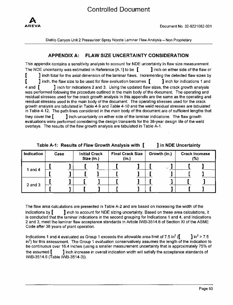
This appendix contains a sensitivity analysis to account for NDE uncertainty in flaw size measurement.The NDE uncertainty was estimated in Reference [A.1] to be [ ] inch on either side of the flaw or[ ] inch total for the axial dimension of the laminar flaws. Incrementing the detected flaw sizes by
[ inch, the flaw size to be used for flaw evaluation becomes [ ] inch for indications 1 and4 and [ ] inch for indications 2 and 3. Using the updated flaw sizes, the crack growth analysiswas performed following the procedure outlined in the main body of the document. The operating andresidual stresses used for the crack growth analysis in this appendix are the same as the operating andresidual stresses used in the main body of the document. The operating stresses used for the crackgrowth analysis are tabulated in Table 4-9 and Table 4-10 and the weld residual stresses are tabulatedin Table 4-12. The path lines considered in the main body of the document are of sufficient lengths thatthey cover the [ ] inch uncertainty on either side of the laminar indications. The flaw growthevaluations were performed considering the design transients for the 38-year design life of the weldoverlays. The results of the flaw growth analysis are tabulated in Table A-I.
Table A-I: Results of Flaw Growth Analysis with [ ] in NDE Uncertainty
Indication Case Initial Crack Final Crack Size Growth (in.) Crack IncreaseSize (in.) (in.) (%)
1 and 4 [ ] [ ) [ ] [ ] [ ]
2 and 3
The flaw area calculations are presented in Table A-2 and are based on increasing the width of theindications by [ ] inch to account for NDE sizing uncertainty. Based on these area calculations, itis concluded that the laminar indications in the second grouping for Indications 1 and 4, and Indications2 and 3, meet the laminar flaw acceptance standards in Article IWB-3514.6 of Section XI of the ASMECode after 38 years of plant operation.
Indications 1 and 4 evaluated as Group 1 exceeds the allowable area limit of 7.5 in2 (' 1 in2 > 7.5in2) for this assessment. The Group 1 evaluation conservatively assumes the length of the indication tobe continuous over 16.4 inches (using a smaller measurement uncertainty that is approximately 75% ofthe assumed [ ] inch increase in overall indication width will satisfy the acceptance standards ofIWB-3514.6 (Table IWB-3514-3)).
Page 50
AAR EVA
Controlled Document
Document No. 32-9221082-001
Diablo Canyon Unit 2 Pressurizer Spray Nozzle Laminar Flaw Analysis - Non Proprietary
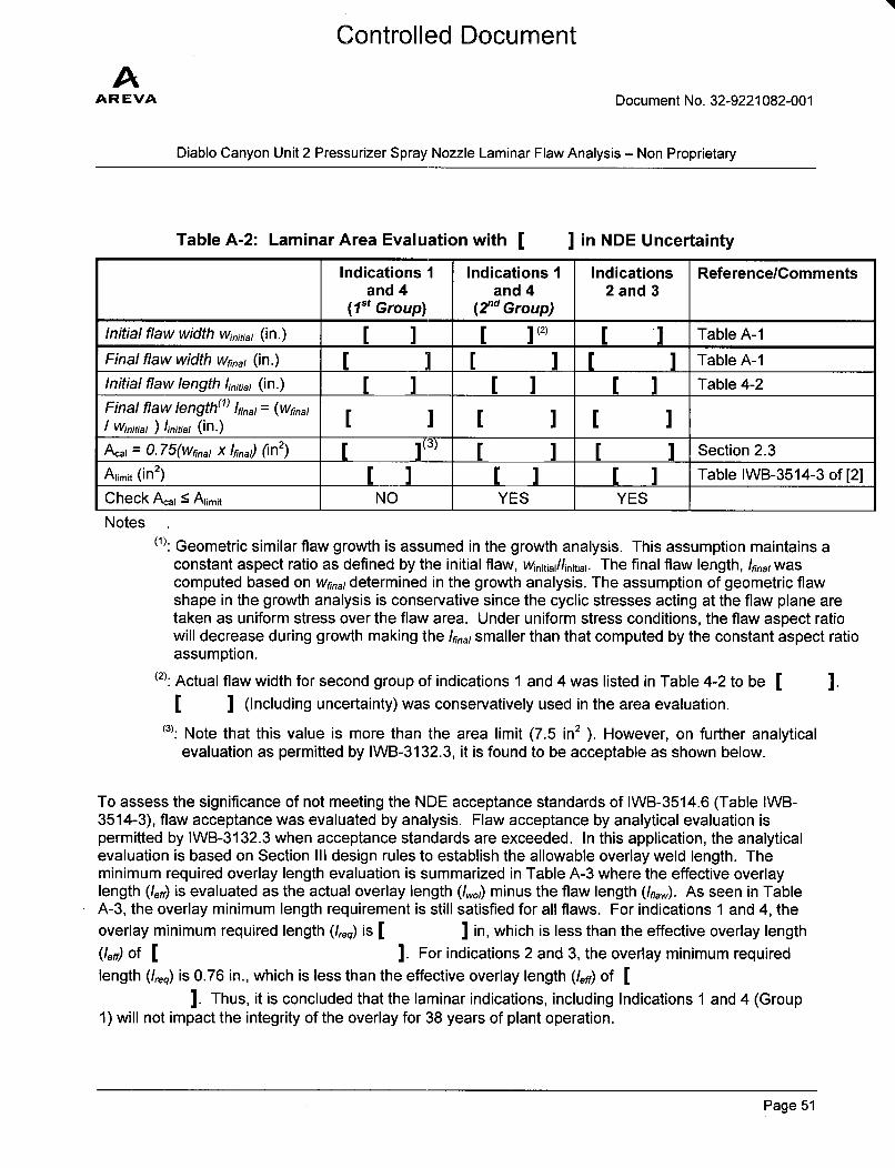
Table A-2: Laminar Area Evaluation with [ ] in NDE Uncertainty
Indications 1 Indications 1 Indications Reference/Commentsand 4 and 4 2 and 3
(1st Group) (2 nd Group)
Initial flaw width winitia, (in.) [ ] [ 1(2) [ ] Table A-1
Final flaw width wfinal (in.) [ ] [ ] [ ] Table A-1Initial flaw length linitial (in.) [ ] [ ] [ ] Table 4-2
Final flaw length(1) final = (wfina,I Winitial ) 'initial (in.) __]___]___]
A., = 0. 75(Wf0 na x final) (in 2) [ ](3) [ [ Section 2.3
Aiimit (in2) [ ] [ ] [ ] Table IWB-3514-3 of [2]
Check A.i < Aiimit NO YES YES
Notes(1): Geometric similar flaw growth is assumed in the growth analysis. This assumption maintains a
constant aspect ratio as defined by the initial flaw, Winitiai/linitiai. The final flaw length, 'final wascomputed based on wfinal determined in the growth analysis. The assumption of geometric flawshape in the growth analysis is conservative since the cyclic stresses acting at the flaw plane aretaken as uniform stress over the flaw area. Under uniform stress conditions, the flaw aspect ratiowill decrease during growth making the final smaller than that computed by the constant aspect ratioassumption.
(2): Actual flaw width for second group of indications 1 and 4 was listed in Table 4-2 to be [I" ] (Including uncertainty) was conservatively used in the area evaluation.
(3): Note that this value is more than the area limit (7.5 in2 ). However, on further analytical
evaluation as permitted by IWB-3132.3, it is found to be acceptable as shown below.
To assess the significance of not meeting the NDE acceptance standards of IWB-3514.6 (Table IWB-3514-3), flaw acceptance was evaluated by analysis. Flaw acceptance by analytical evaluation ispermitted by IWB-3132.3 when acceptance standards are exceeded. In this application, the analyticalevaluation is based on Section III design rules to establish the allowable overlay weld length. Theminimum required overlay length evaluation is summarized in Table A-3 where the effective overlaylength (/eff) is evaluated as the actual overlay length (/wol) minus the flaw length (Iflaw). As seen in TableA-3, the overlay minimum length requirement is still satisfied for all flaws. For indications 1 and 4, theoverlay minimum required length (Ireq) is ] ] in, which is less than the effective overlay length
(len') of [ ]. For indications 2 and 3, the overlay minimum requiredlength (Ireq) is 0.76 in., which is less than the effective overlay length (len') of [
]. Thus, it is concluded that the laminar indications, including Indications 1 and 4 (Group1) will not impact the integrity of the overlay for 38 years of plant operation.
I.
Page 51
AAREVA
Controlled Document
Document No. 32-9221082-001
Diablo Canyon Unit 2 Pressurizer Spray Nozzle Laminar Flaw Analysis - Non Proprietary
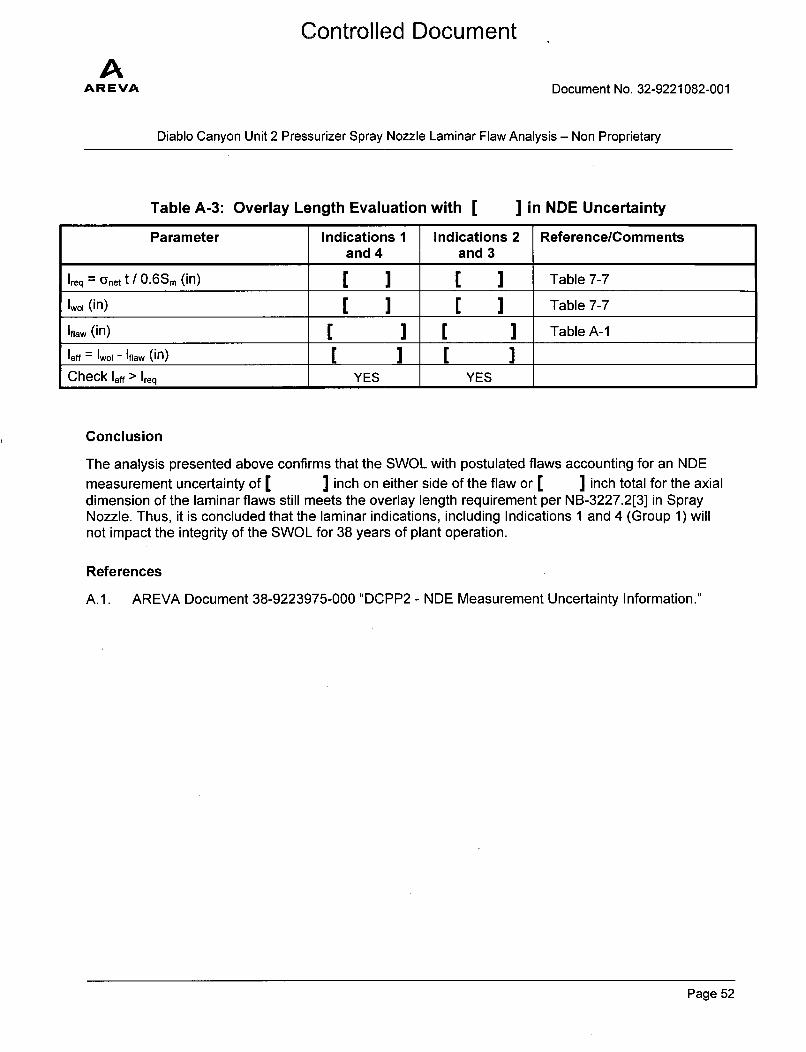
Table A-3: Overlay Length Evaluation with [ ] in NDE UncertaintyParameter Indications 1 Indications 2 Reference/Comments
and 4 and 3
Ireq -- anet t /I0.6Sm (in) [ ] [ ] Table 7-7
1,01 (in) [ I [ ] Table 7-7
Iflaw (in) [ ] [ I Table A-1
leff = Iwo,-Ifaw (in) ]Check leff> Ireq YES YES
Conclusion
The analysis presented above confirms that the SWOL with postulated flaws accounting for an NDEmeasurement uncertainty of [ ] inch on either side of the flaw or [ ] inch total for the axialdimension of the laminar flaws still meets the overlay length requirement per NB-3227.2[3] in SprayNozzle. Thus, it is concluded that the laminar indications, including Indications 1 and 4 (Group 1) willnot impact the integrity of the SWOL for 38 years of plant operation.
References
A.l. AREVA Document 38-9223975-000 "DCPP2 - NDE Measurement Uncertainty Information."
Page 52