Embed Size (px)
Citation preview
Attachment A:
I. Background and Analysis A. Existing Land Use and Existing and Ultimate Development Hydrology Figure 1: Vicinity Map Figure 1A: Location Map Table 1: Summary of Watershed Land Use Areas at MD Route 464 over Catoctin Creek.
Table 2: Summary of TR-20 Flows Simulated at MD Route 464 over Catoctin Creek.
B. Estimated Bankfull Flow and Channel Geometry Based on USFWS Curves
Table 3: Summary of Stream Parameters for MD 464 over Catoctin Creek. Figure 2: Physiographic Provinces and Their Subdivisions in Maryland C. Historical and Contemporary Channel and Valley Modifications
Figure 3: Article Regarding Grist Mills in the Region. Figure 4: Map Showing Mills and Forges in the Region in 1808. Figure 5: Map Showing Grist and Saw Mills in the Region in 1873. Figure 6: Substructure Details from 1933 Construction Drawings for Current MD Route 464 Bridge over Catoctin Creek. Figure 7: 1933 Plan and Cross Section Views of Current MD Route 464 Bridge over Catoctin Creek.
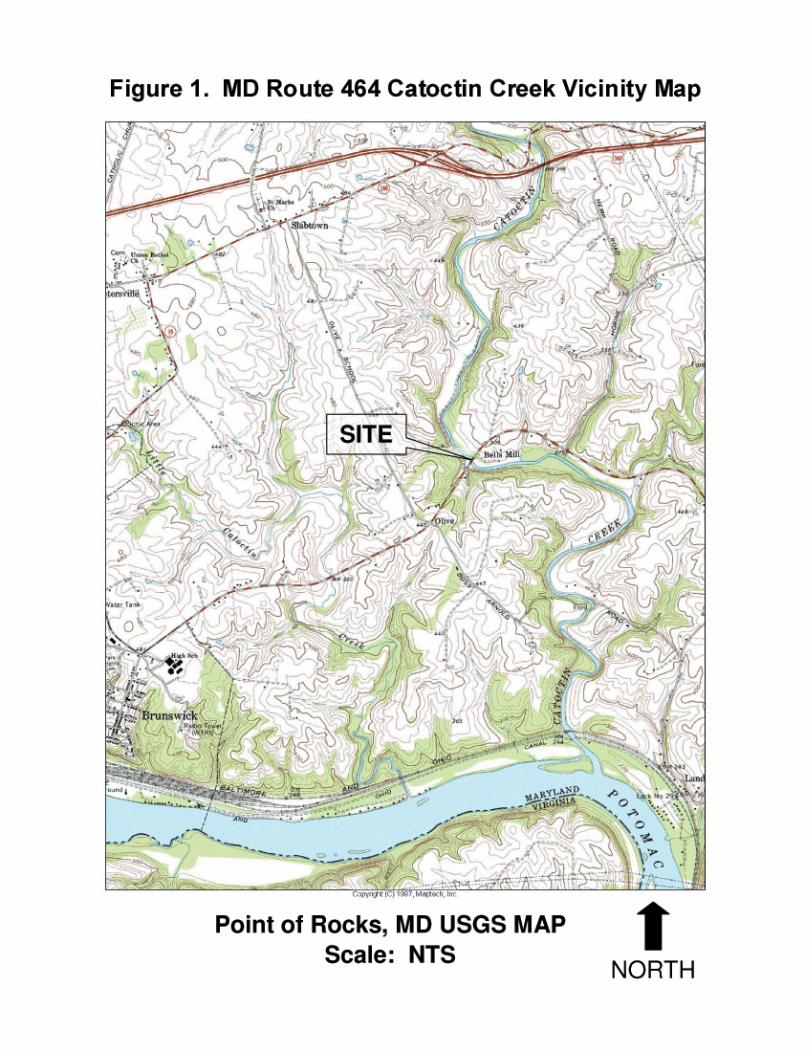
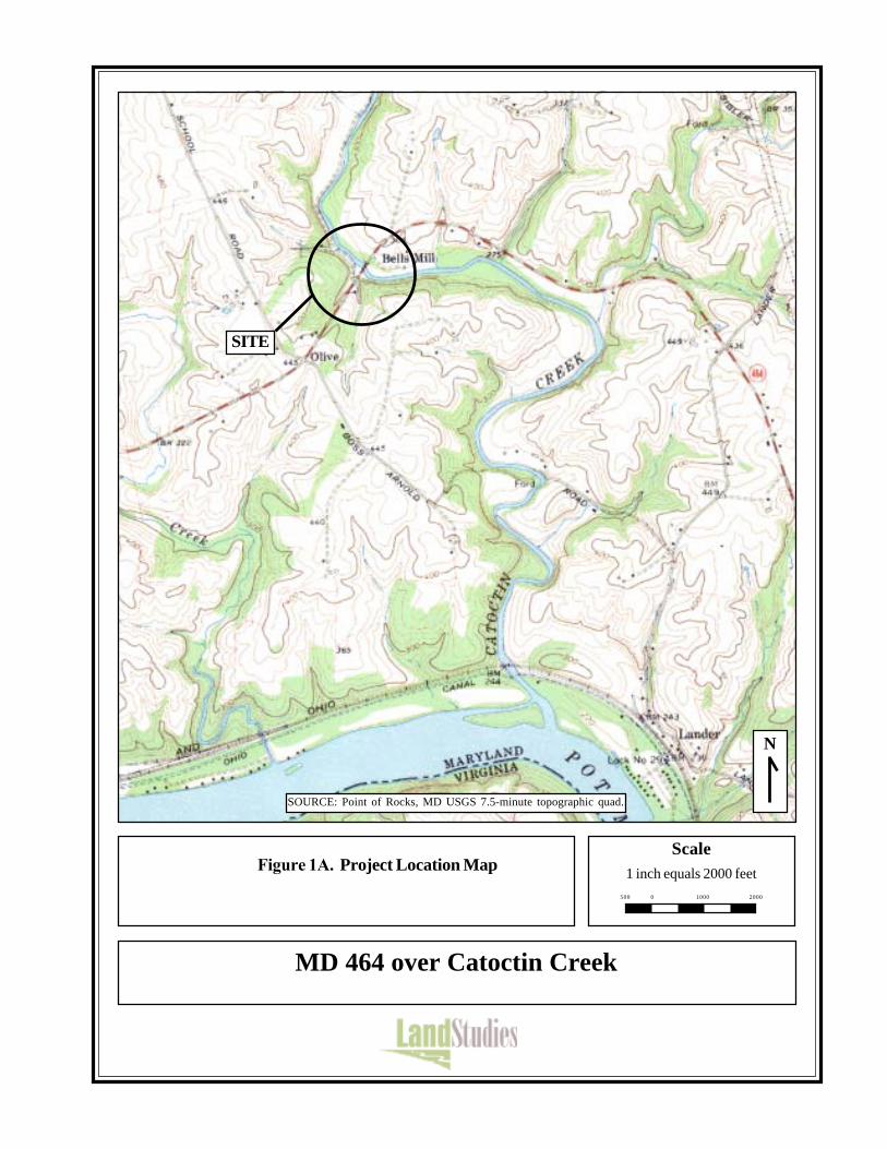
Figure 1A. Project Location MapScale
1 inch equals 2000 feet
N
MD 464 over Catoctin Creek
SITE
SOURCE: Point of Rocks, MD USGS 7.5-minute topographic quad.
0500 1000 2000
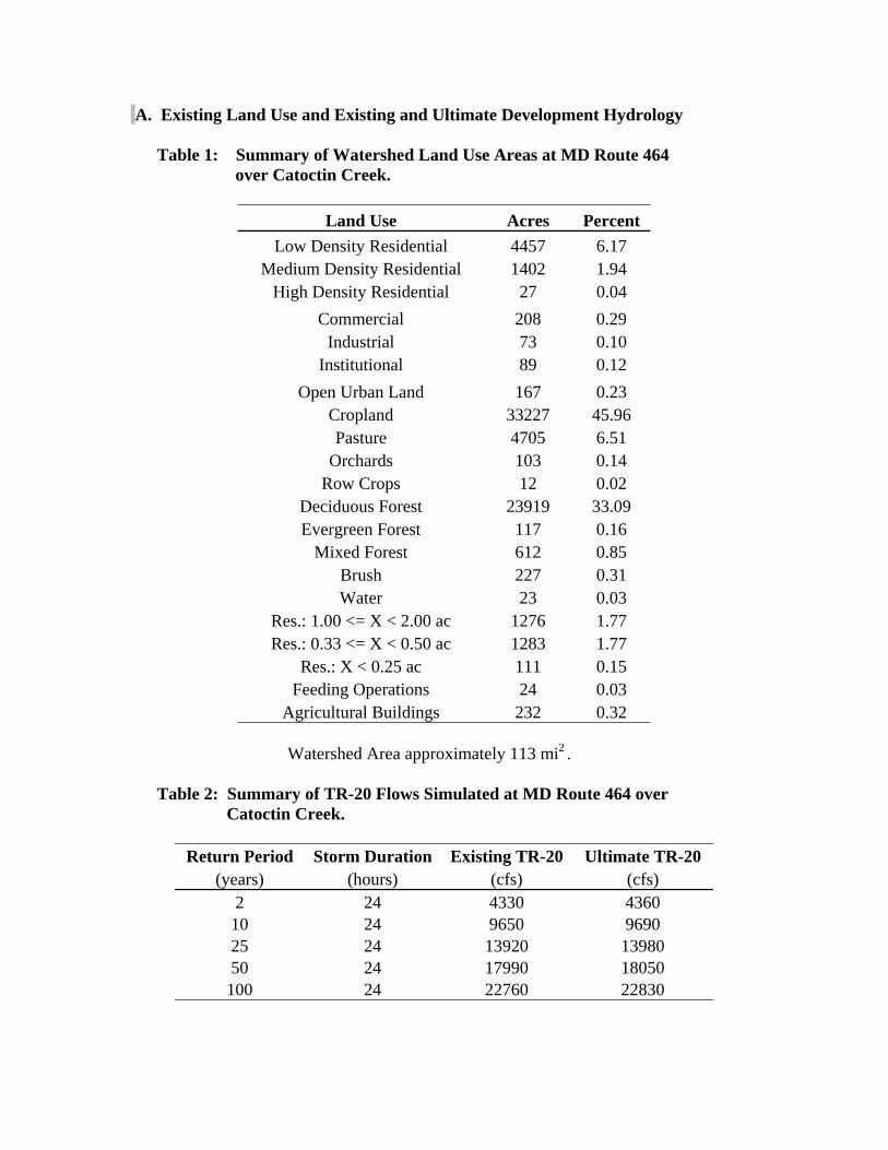
A. Existing Land Use and Existing and Ultimate Development Hydrology
Table 1: Summary of Watershed Land Use Areas at MD Route 464 over Catoctin Creek.
Land Use Acres Percent
Low Density Residential 4457 6.17 Medium Density Residential 1402 1.94
High Density Residential 27 0.04 Commercial 208 0.29
Industrial 73 0.10 Institutional 89 0.12
Open Urban Land 167 0.23 Cropland 33227 45.96 Pasture 4705 6.51
Orchards 103 0.14 Row Crops 12 0.02
Deciduous Forest 23919 33.09 Evergreen Forest 117 0.16
Mixed Forest 612 0.85 Brush 227 0.31 Water 23 0.03
Res.: 1.00 <= X < 2.00 ac 1276 1.77 Res.: 0.33 <= X < 0.50 ac 1283 1.77
Res.: X < 0.25 ac 111 0.15 Feeding Operations 24 0.03
Agricultural Buildings 232 0.32 Watershed Area approximately 113 mi2.
Table 2: Summary of TR-20 Flows Simulated at MD Route 464 over Catoctin Creek.
Return Period Storm Duration Existing TR-20 Ultimate TR-20
(years) (hours) (cfs) (cfs) 2 24 4330 4360 10 24 9650 9690 25 24 13920 13980 50 24 17990 18050 100 24 22760 22830
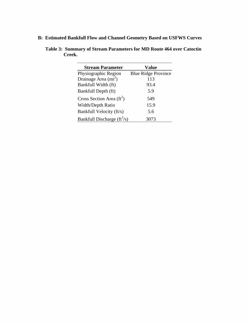
B: Estimated Bankfull Flow and Channel Geometry Based on USFWS Curves Table 3: Summary of Stream Parameters for MD Route 464 over Catoctin Creek.
Stream Parameter Value
Physiographic Region Drainage Area (mi2) Bankfull Width (ft)
Blue Ridge Province 113 93.4
Bankfull Depth (ft) 5.9 Cross Section Area (ft2) 549 Width/Depth Ratio 15.9 Bankfull Velocity (ft/s) 5.6 Bankfull Discharge (ft3/s) 3073
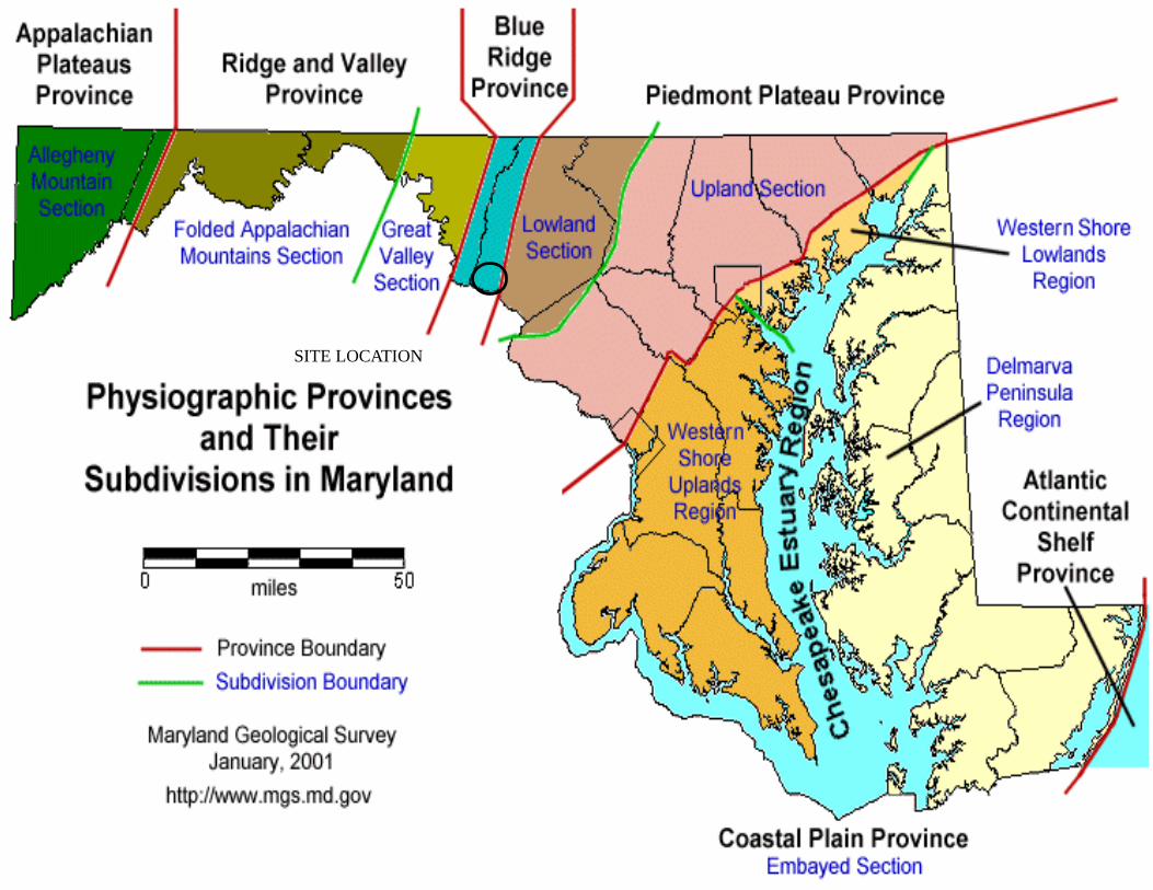
SITE LOCATION
C. Historical and Contemporary Channel and Valley Modifications Catoctin Creek powered many mills within the watershed in the 18th, 19th, and 20th centuries. There are numerous articles and maps describing and identifying the dams and mills along Catoctin Creek (previously Abraham Creek). These references include: (a) “The Grist Mills of Frederick County,” Moser, Harold, The Valley Register,
Middletown, MD, December 7, 1984; (b) “Old Mills on Catoctin Creek,” Martz, Ralph, The News, Frederick, MD, February
26, 1973; (c) 1873 Atlas of Frederick County Maryland; C.O. Titus &Co.; and (d) Map of Frederick and Washington Counties, 1808, Charles Varle.
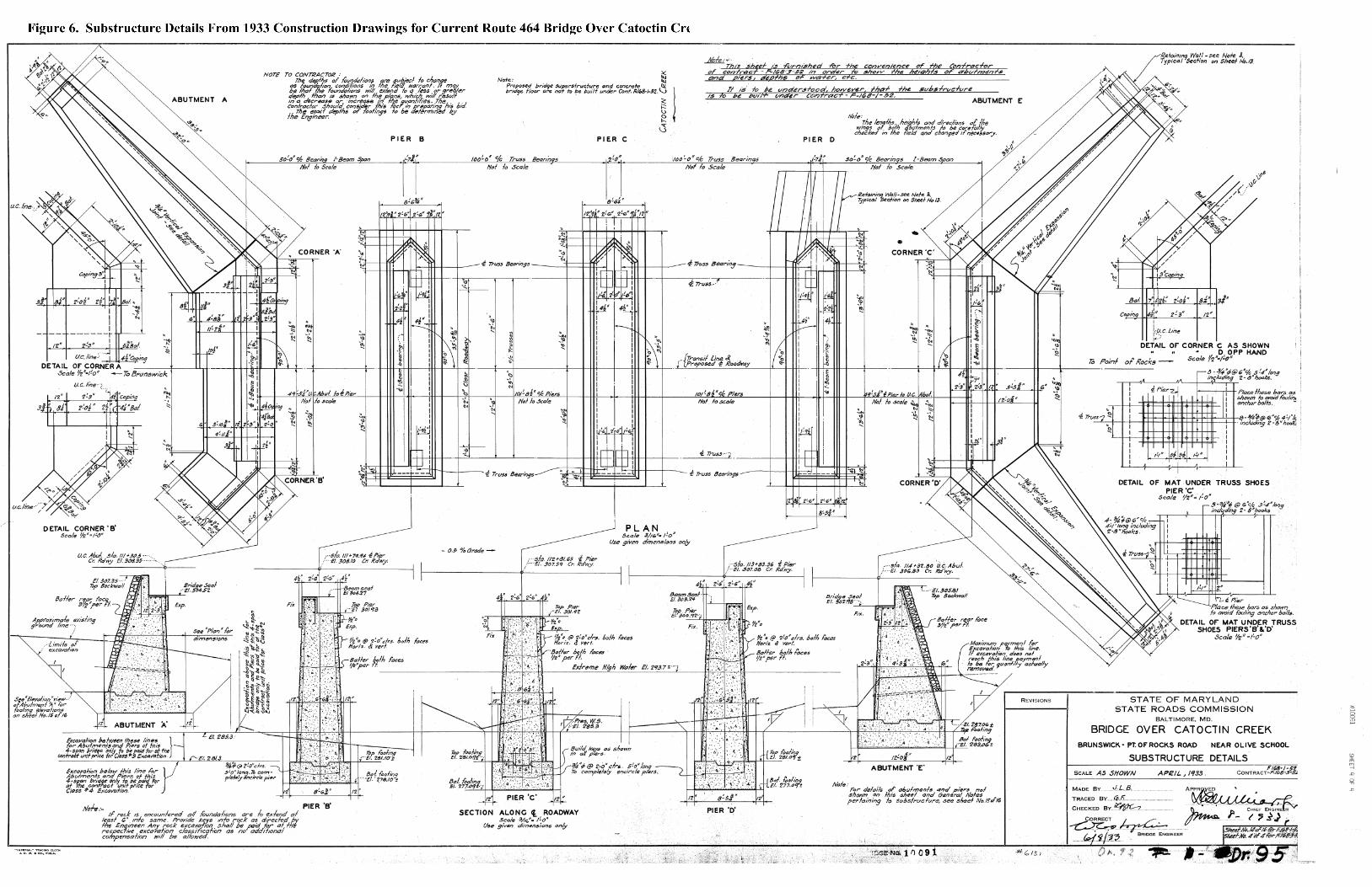
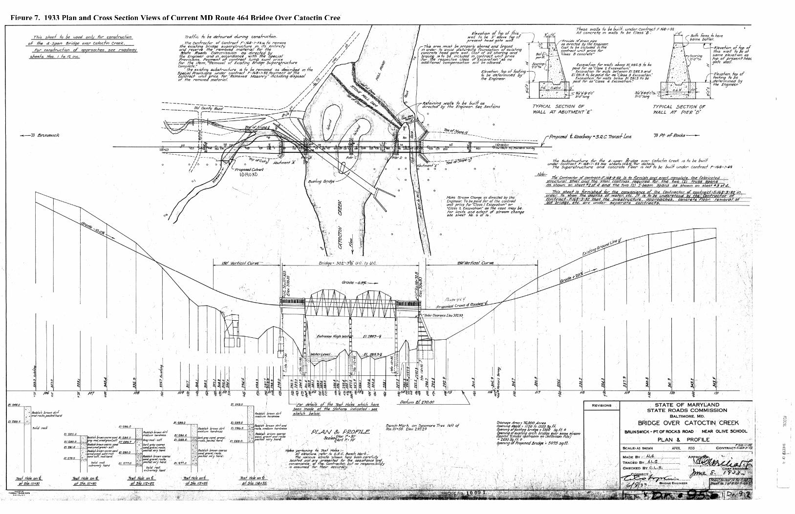
As of 1808, there were 104 grist mills operating within Frederick County. Within Catoctin Creek and its tributaries, there were more than 67 mill sites identified, with approximately 48 mills along the Catoctin Creek. Besides the grist and flour mills on the Catoctin Creek, there were saw, cider, fulling, linseed oil, plaster, and powder mills. Some of the previous dams and roads that had a more direct influence on the MD Route 464 crossing of Catoctin Creek include the dam/mills located approximately 1.6 miles downstream at the previous Arnold Road crossing of Catoctin Creek and Bells Mill, which is located a few hundred feet downstream of MD Route 464, with the dam located at the crossing of MD Route 464. There are many other dams located within the watershed including one near MD Route 180 over the Catoctin Creek, approximately 1.5 miles upstream of the crossing. As observed in the field assessment, the banks along the Catoctin Creek consist mostly of fine, laminated sediments, consistent with mill dam deposits, that are now being eroded. The more linear pattern of the Creek shown in the 1808 Map of Frederick County differs significantly from its current path. There appears to be significant relocation of the Creek, now typically located along the east and west valley walls. This relocation possibly occurred as a result of the construction of the mill dams and roads. This relocation also appears to have occurred when the bed elevation was significantly higher. The bank sediments represent mill pond or dam sediments. The stream is currently going through vertical degradation in some locations and exhibiting lateral movement in others. The stream is predominately located along the valley wall and is currently eroding bedrock outcrops, with lateral movement being away from the bedrock. The 1873 Atlas of Frederick County (See Attachment A for Map) also shows a road (currently abandoned) that runs parallel to Catoctin Creek with two crossings from Arnold Road to existing MD Route 464. There are numerous locations where large bedrock boulders are scattered along the Creek. One of the boulders approximately 1,500 feet downstream of the bridge has a bore hole (Photo 37), which represents blasting of the bedrock for either utilities or dam construction or to improve flow passage for the mill or logging operations. The old bridge plans, dated 1933 and shown in Attachment A, show the previous two-span bridge located with the east abutment approximately 100 feet downstream, between piers C and D of the current bridge; the west abutment was located at Pier B. The
unnamed tributary currently entering upstream and along the west abutment was previously entering Catoctin Creek downstream of the west abutment. The east abutment (Photo 85) is in severe disrepair and currently obstructing exit flows from the bridge. There are no signs of the older pier or east abutment. However, there is significant deposition in the locations of those older substructure units, so any evidence may be buried (Photo 83). Also, the old drawings show two islands between the dam and the 1933 bridge. Currently, the deposition extends from approximately 100 feet downstream to approximately 100 feet upstream of the dam. There has been significant loss of capacity through the bridge since 1933. The old bridge plans, dated 1933, show a stone mill dam extending from the west hillside to a land feature between the easternmost pier (Pier D) and the east abutment of the proposed bridge. That land feature has since eroded away, leaving the two retaining walls that tied the concrete gates to Pier D and the east abutment. The mill race went over concrete gates along the east abutment to the mill building approximately 1,000 feet downstream. Portions of the retaining wall have collapsed (Photo 91), as have the concrete gates. The remnants are located immediately upstream of Pier D.
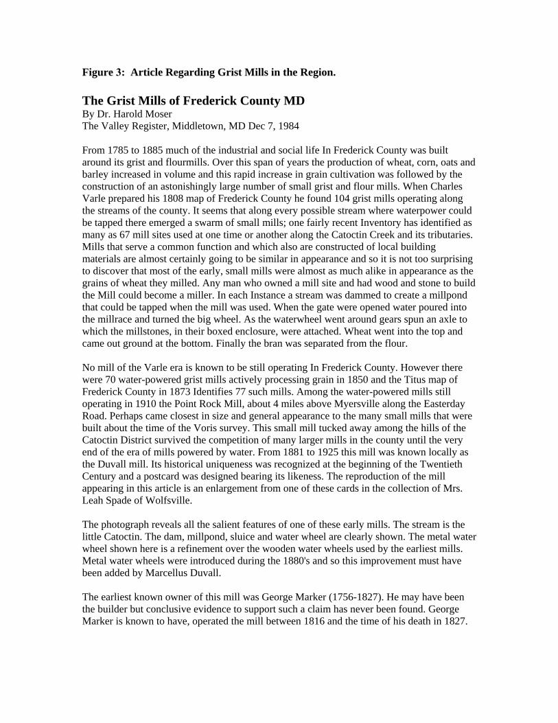
Figure 3: Article Regarding Grist Mills in the Region. The Grist Mills of Frederick County MD By Dr. Harold Moser The Valley Register, Middletown, MD Dec 7, 1984 From 1785 to 1885 much of the industrial and social life In Frederick County was built around its grist and flourmills. Over this span of years the production of wheat, corn, oats and barley increased in volume and this rapid increase in grain cultivation was followed by the construction of an astonishingly large number of small grist and flour mills. When Charles Varle prepared his 1808 map of Frederick County he found 104 grist mills operating along the streams of the county. It seems that along every possible stream where waterpower could be tapped there emerged a swarm of small mills; one fairly recent Inventory has identified as many as 67 mill sites used at one time or another along the Catoctin Creek and its tributaries. Mills that serve a common function and which also are constructed of local building materials are almost certainly going to be similar in appearance and so it is not too surprising to discover that most of the early, small mills were almost as much alike in appearance as the grains of wheat they milled. Any man who owned a mill site and had wood and stone to build the Mill could become a miller. In each Instance a stream was dammed to create a millpond that could be tapped when the mill was used. When the gate were opened water poured into the millrace and turned the big wheel. As the waterwheel went around gears spun an axle to which the millstones, in their boxed enclosure, were attached. Wheat went into the top and came out ground at the bottom. Finally the bran was separated from the flour. No mill of the Varle era is known to be still operating In Frederick County. However there were 70 water-powered grist mills actively processing grain in 1850 and the Titus map of Frederick County in 1873 Identifies 77 such mills. Among the water-powered mills still operating in 1910 the Point Rock Mill, about 4 miles above Myersville along the Easterday Road. Perhaps came closest in size and general appearance to the many small mills that were built about the time of the Voris survey. This small mill tucked away among the hills of the Catoctin District survived the competition of many larger mills in the county until the very end of the era of mills powered by water. From 1881 to 1925 this mill was known locally as the Duvall mill. Its historical uniqueness was recognized at the beginning of the Twentieth Century and a postcard was designed bearing its likeness. The reproduction of the mill appearing in this article is an enlargement from one of these cards in the collection of Mrs. Leah Spade of Wolfsville. The photograph reveals all the salient features of one of these early mills. The stream is the little Catoctin. The dam, millpond, sluice and water wheel are clearly shown. The metal water wheel shown here is a refinement over the wooden water wheels used by the earliest mills. Metal water wheels were introduced during the 1880's and so this improvement must have been added by Marcellus Duvall. The earliest known owner of this mill was George Marker (1756-1827). He may have been the builder but conclusive evidence to support such a claim has never been found. George Marker is known to have, operated the mill between 1816 and the time of his death in 1827.
Jacob Palmer owned the mill between 1839 and 1866 and under his management the mill enjoyed its most prosperous years. By 1850 the mill was processing annually 8000 bushels of grain and turning out 1100 barrels of flour. Miller Palmer added a sawmill to the operation and he employed three laborers to help run the plant. The prevailing wage for a sawmill assistant was $16 per month. Mill hands were paid $20 per month. The mill barely survived the economic depression in the early 1870's. Mill ownership changed three times between 1866 and 1881 and finally, on April 4, 1881, the mill was sold to Marcellus Duvall who was the last Miller to operate the Facility. At 45 years of age he was an experienced miller coming from a family of millers. However, his experience and skill as a milletr were not enough to overcome the tide of change that was sweeping the milling industry. Improved transportation and the emergence of large urban milling centers gradually brought to an end the era of local, water-powered grist and flour mills. In 1903, at the age of 67, Marcellus Duvall had the ownership of the mill transferred to his wife, Cornelia (Stottlemyer) Duvall. The mill property remained with the Duvall family until 1926 (Marcellus died In 1925) but the mill must have ceased operation a number of years before the property was sold. Today only a small fragment of a mill wall remains to mark the site of the once busy center. Neighbors report that much of the mill area has been destroyed by vandals. Dense undergrowth now borders the headwaters of the Catoctin creek and a fine country home now stands at the place where the miller once lived.
Duvall Mill, Myersville MD, along the Easterday Road also know as Point Rock Mill, and owned by George Marker between 1815-1827
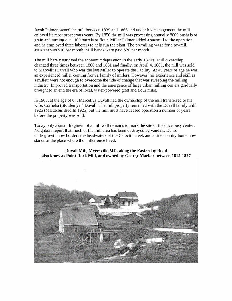
Figure 4. Map Showing Mills and Forges in the Region in 1808
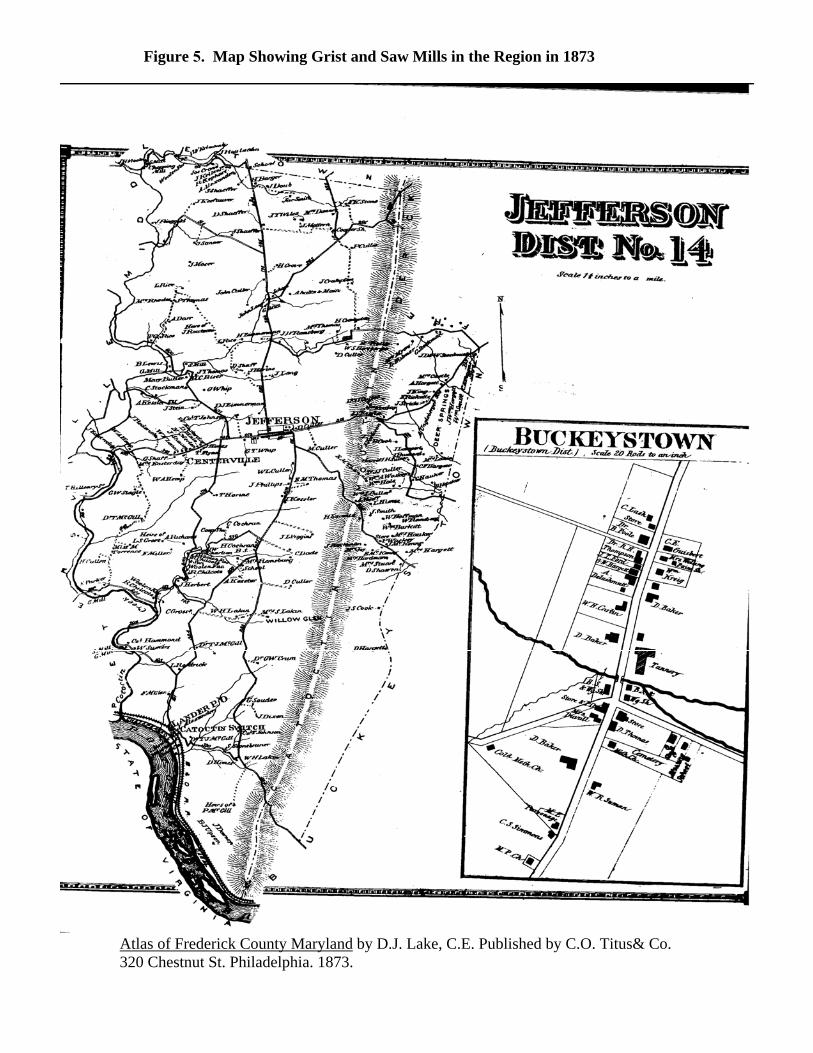
Figure 5. Map Showing Grist and Saw Mills in the Region in 1873
Atlas of Frederick County Maryland by D.J. Lake, C.E. Published by C.O. Titus& Co. 320 Chestnut St. Philadelphia. 1873.

Attachment A:
II. Visual Assessment A. Base Level Reach
B. Project Reach
C. Supply Reach
II. Visual Assessment A. Base level Reach. The downstream-most base-level point used in the assessment is approximately 5,000 feet downstream of MD Route 464 over Catoctin Creek (Structure #10091). The location of the base-level reach begins 5,000 feet downstream and extends to the millrace approximately 1,000 feet downstream of Structure #10091. The description of the base-level reach is broken into four segments highlighting different features. 5,000 feet downstream of Structure #10091 to an Unnamed Tributary Confluence at a distance of 400 feet upstream.
Approximately 5,000 feet downstream of MD Route 464 the valley becomes confined by the east and west valley walls at the downstream end of a meander bend. The base-level control consists of exposed bedrock of unknown durability. This location is a degraded, local base-level control (Photo 4). A low-flow high-gradient feature (LFHG) or armored riffle, approximately 200
feet long, is composed of bedrock outcrops and large pieces of fractured bedrock. Bedrock outcrops and forest constitute most of the banks. A large mid-channel bar within this LFHG is heavily vegetated with young trees.
The bar material consists of large, angular bedrock fragments and quartz gravels and sands. There is some debris collected within the island. An unnamed tributary enters from the east along the valley wall. The tributary is
an entrenched F-type channel with bed material composed of bedrock and quartz gravels. The channel has a ford to get back and forth through an automobile junk yard. Removal of the downstream LFHG feature will cause further incision and lateral movement to the tributary. This tributary supplements the bed load and sediments forming the large mid-channel bar immediately downstream. At the top of the riffle, there are some large exposed bedrock outcrops or
boulders, which may indicate the presence of a dam in this location. There are signs of lateral movement in a westerly direction. The channel classification in this location is F-type.
Unnamed Tributary Confluence to Hovine Run Confluence at a distance of approximately 2,000 feet upstream.
The base level for this segment begins at the top of the steep LFHG feature just downstream of the unnamed tributary described above. Degradation of that steep riffle will cause incision and increase lateral movement in an easterly direction. Within this segment there is a single, long, and mildly sloped LFHG feature
composed of quartz gravels and bedrock fragments with bars. The LFHG feature is located approximately 1,200 feet upstream of the unnamed tributary confluence, where the stream moves from the west valley wall into the east bank or terrace. For most of this segment, the channel is located along the west valley wall.
Erosion is occurring along the valley wall where bedrock outcrops are being scoured and tree fall is occurring. The east bank height goes from 9 feet at the lower end (Photo 12) to 8 feet at the upper end. The banks consist of fine, laminated sediments, including a highly cohesive layer below and above the water surface. At the downstream end of this segment there are no signs of gravel or bedrock. The east bank at the upper end of the segment has fine, laminated
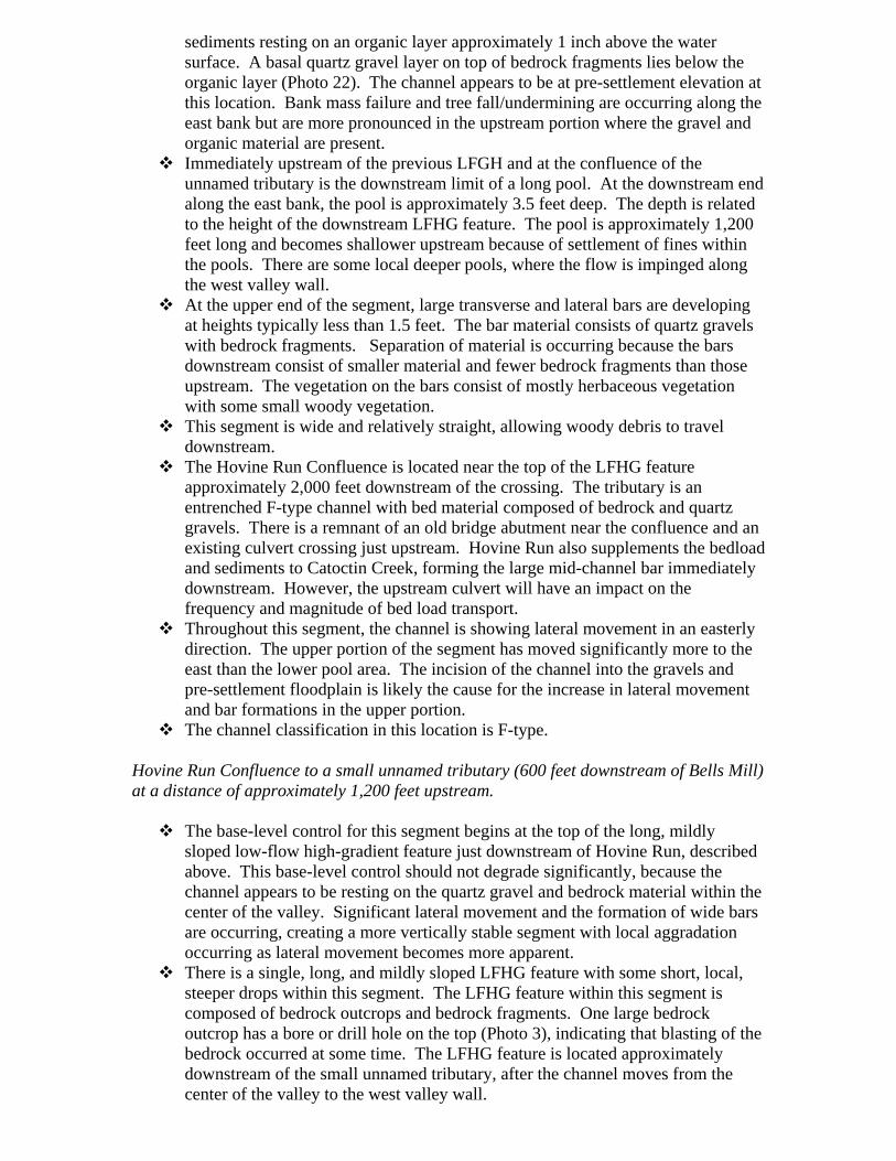
sediments resting on an organic layer approximately 1 inch above the water surface. A basal quartz gravel layer on top of bedrock fragments lies below the organic layer (Photo 22). The channel appears to be at pre-settlement elevation at this location. Bank mass failure and tree fall/undermining are occurring along the east bank but are more pronounced in the upstream portion where the gravel and organic material are present. Immediately upstream of the previous LFGH and at the confluence of the
unnamed tributary is the downstream limit of a long pool. At the downstream end along the east bank, the pool is approximately 3.5 feet deep. The depth is related to the height of the downstream LFHG feature. The pool is approximately 1,200 feet long and becomes shallower upstream because of settlement of fines within the pools. There are some local deeper pools, where the flow is impinged along the west valley wall. At the upper end of the segment, large transverse and lateral bars are developing
at heights typically less than 1.5 feet. The bar material consists of quartz gravels with bedrock fragments. Separation of material is occurring because the bars downstream consist of smaller material and fewer bedrock fragments than those upstream. The vegetation on the bars consist of mostly herbaceous vegetation with some small woody vegetation. This segment is wide and relatively straight, allowing woody debris to travel
downstream. The Hovine Run Confluence is located near the top of the LFHG feature
approximately 2,000 feet downstream of the crossing. The tributary is an entrenched F-type channel with bed material composed of bedrock and quartz gravels. There is a remnant of an old bridge abutment near the confluence and an existing culvert crossing just upstream. Hovine Run also supplements the bedload and sediments to Catoctin Creek, forming the large mid-channel bar immediately downstream. However, the upstream culvert will have an impact on the frequency and magnitude of bed load transport. Throughout this segment, the channel is showing lateral movement in an easterly
direction. The upper portion of the segment has moved significantly more to the east than the lower pool area. The incision of the channel into the gravels and pre-settlement floodplain is likely the cause for the increase in lateral movement and bar formations in the upper portion. The channel classification in this location is F-type.
Hovine Run Confluence to a small unnamed tributary (600 feet downstream of Bells Mill) at a distance of approximately 1,200 feet upstream.
The base-level control for this segment begins at the top of the long, mildly sloped low-flow high-gradient feature just downstream of Hovine Run, described above. This base-level control should not degrade significantly, because the channel appears to be resting on the quartz gravel and bedrock material within the center of the valley. Significant lateral movement and the formation of wide bars are occurring, creating a more vertically stable segment with local aggradation occurring as lateral movement becomes more apparent. There is a single, long, and mildly sloped LFHG feature with some short, local,
steeper drops within this segment. The LFHG feature within this segment is composed of bedrock outcrops and bedrock fragments. One large bedrock outcrop has a bore or drill hole on the top (Photo 3), indicating that blasting of the bedrock occurred at some time. The LFHG feature is located approximately downstream of the small unnamed tributary, after the channel moves from the center of the valley to the west valley wall.
For most of this segment, the channel is located along the west valley wall. Erosion is occurring along the valley wall where bedrock outcrops are being scoured and tree fall is occurring. The east bank height is approximately 7.5 feet in this segment. The banks consist of fine, laminated sediments including a highly cohesive layer below and above the water surface. Bank mass failure and tree fall/undermining are occurring along the east bank but are more pronounced in the downstream portion where the flow is directed off of the west valley wall. Immediately upstream of the previous LFGH and before the channel flows along
the west valley wall is the downstream limit of a long pool. At the downstream end along the east bank, the pool is approximately 3.5 feet deep. The depth is related to the height of the downstream LFHG feature. There are some local deeper pools where the flow is impinged along the west valley wall. At the upper end of the segment, benches or side bars have formed along the east
bank at heights typically less than 2.5 feet. The bar material consists of quartz gravels with bedrock fragments. The vegetation on the bars consists of mostly herbaceous vegetation with some small woody vegetation. This segment is wide and relatively straight, allowing woody debris to travel
downstream. The confluence of a very small, unnamed tributary is located near the top of the
LFHG feature approximately 1,500 feet downstream of the crossing. The tributary is an entrenched F-type channel with bed material of fines because it is located within the fine, laminated sediments. The tributary is overgrown with herbaceous and woody vegetation. The channel is showing lateral movement in an easterly direction along the lower
portion of this segment. The upper portion of the segment is protected by the large, bedrock outcrops and bedrock bottom. As the lower portion continues to move to the east, the upper portion will continue to move east as well. The channel classification in this location is F-type.
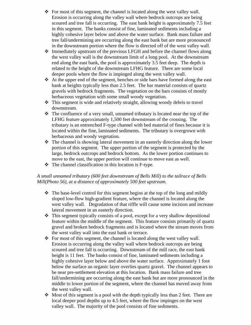
A small unnamed tributary (600 feet downstream of Bells Mill) to the tailrace of Bells Mill(Photo 56), at a distance of approximately 500 feet upstream.
The base-level control for this segment begins at the top of the long and mildly sloped low-flow high-gradient feature, where the channel is located along the west valley wall. Degradation of that riffle will cause some incision and increase lateral movement in an easterly direction. This segment typically consists of a pool, except for a very shallow depositional
feature within the middle of the segment. This feature consists primarily of quartz gravel and broken bedrock fragments and is located where the stream moves from the west valley wall into the east bank or terrace. For most of this segment, the channel is located along the west valley wall.
Erosion is occurring along the valley wall where bedrock outcrops are being scoured and tree fall is occurring. Downstream of the mill race, the east bank height is 11 feet. The banks consist of fine, laminated sediments including a highly cohesive layer below and above the water surface. Approximately 1 foot below the surface an organic layer overlies quartz gravel. The channel appears to be near pre-settlement elevation at this location. Bank mass failure and tree fall/undermining are occurring along the east bank but are more pronounced in the middle to lower portion of the segment, where the channel has moved away from the west valley wall. Most of this segment is a pool with the depth typically less than 2 feet. There are
local deeper pool depths up to 4.5 feet, where the flow impinges on the west valley wall. The majority of the pool consists of fine sediments.

In the middle of this segment, large transverse and lateral bars are developing at heights typically less than 1.5 feet. The bar material consists of quartz gravels with bedrock fragments. The vegetation on the bars consists of mostly herbaceous vegetation. This segment is wide and relatively straight, allowing woody debris to travel
downstream. The tailrace of the mill is located at the top of this segment and provides very
little input of bed load. The mill race is eroding and the building is abandoned and in disrepair. Throughout this segment, the channel is exhibiting lateral movement in an
easterly direction. The middle and lower portions of this segment have moved significantly more to the east than has the upper portion. The channel classification in this location is F-type.
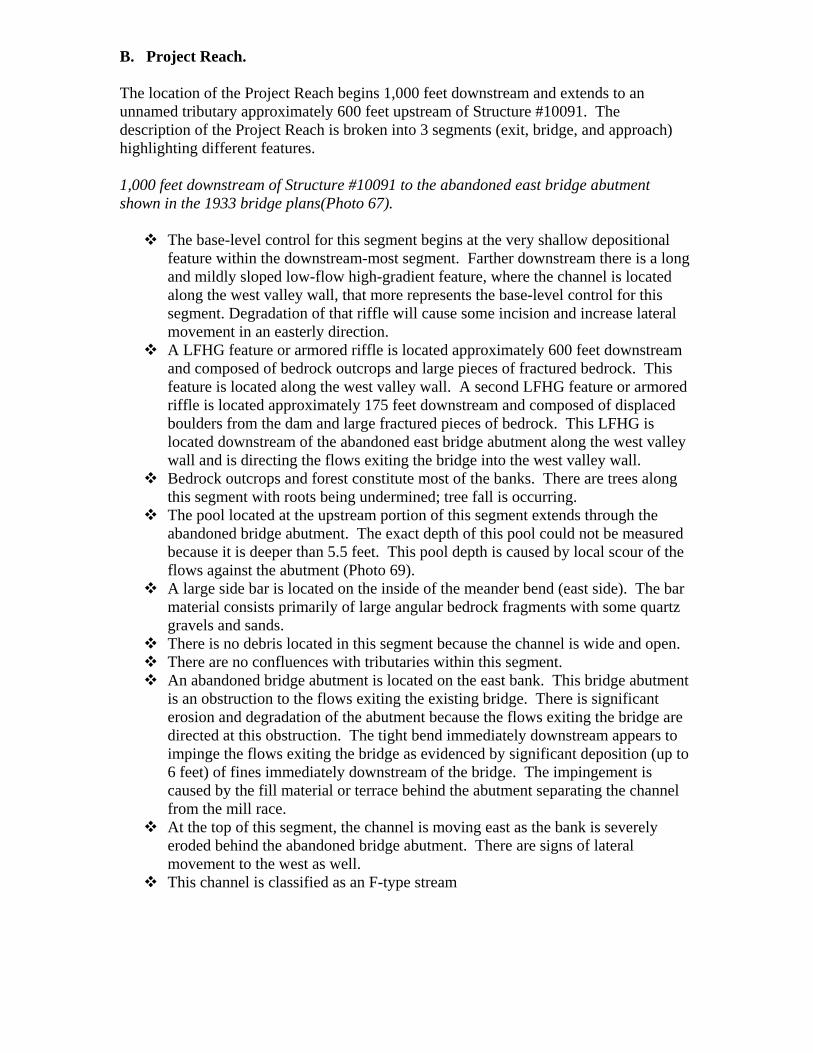
B. Project Reach. The location of the Project Reach begins 1,000 feet downstream and extends to an unnamed tributary approximately 600 feet upstream of Structure #10091. The description of the Project Reach is broken into 3 segments (exit, bridge, and approach) highlighting different features. 1,000 feet downstream of Structure #10091 to the abandoned east bridge abutment shown in the 1933 bridge plans(Photo 67).
The base-level control for this segment begins at the very shallow depositional feature within the downstream-most segment. Farther downstream there is a long and mildly sloped low-flow high-gradient feature, where the channel is located along the west valley wall, that more represents the base-level control for this segment. Degradation of that riffle will cause some incision and increase lateral movement in an easterly direction. A LFHG feature or armored riffle is located approximately 600 feet downstream
and composed of bedrock outcrops and large pieces of fractured bedrock. This feature is located along the west valley wall. A second LFHG feature or armored riffle is located approximately 175 feet downstream and composed of displaced boulders from the dam and large fractured pieces of bedrock. This LFHG is located downstream of the abandoned east bridge abutment along the west valley wall and is directing the flows exiting the bridge into the west valley wall. Bedrock outcrops and forest constitute most of the banks. There are trees along
this segment with roots being undermined; tree fall is occurring. The pool located at the upstream portion of this segment extends through the
abandoned bridge abutment. The exact depth of this pool could not be measured because it is deeper than 5.5 feet. This pool depth is caused by local scour of the flows against the abutment (Photo 69). A large side bar is located on the inside of the meander bend (east side). The bar
material consists primarily of large angular bedrock fragments with some quartz gravels and sands. There is no debris located in this segment because the channel is wide and open. There are no confluences with tributaries within this segment. An abandoned bridge abutment is located on the east bank. This bridge abutment
is an obstruction to the flows exiting the existing bridge. There is significant erosion and degradation of the abutment because the flows exiting the bridge are directed at this obstruction. The tight bend immediately downstream appears to impinge the flows exiting the bridge as evidenced by significant deposition (up to 6 feet) of fines immediately downstream of the bridge. The impingement is caused by the fill material or terrace behind the abutment separating the channel from the mill race. At the top of this segment, the channel is moving east as the bank is severely
eroded behind the abandoned bridge abutment. There are signs of lateral movement to the west as well. This channel is classified as an F-type stream
The abandoned East Bridge Abutment shown in the 1933 bridge plans (100 feet downstream of Structure #1009) to150 feet upstream of the crossing..
The base-level control for this segment begins at the low-flow high-gradient feature or armored riffle located downstream of the abandoned bridge abutment. The LFGH consists of displaced boulders from the dam and large fractured pieces of bedrock. Degradation of that riffle will cause some incision and increase lateral movement in an easterly direction. A LFHG feature or armored riffle is located immediately downstream of the
bridge face and extends upstream almost to Pier D. This LFHG is short, steep, and composed of displaced boulders – possibly riprap – and large pieces of fractured bedrock. A second LFHG is located immediately upstream of the bridge face. This LFHG is located where the existing dam has breached (Photo 74). The material is large boulders that formed the dam. The east bank is 12 feet high and composed of fine, laminated sediments with no
indication of gravel or organic layers (Photo 104). The right bank consists primarily of fine sediments upstream and downstream of Structure #10091 and the dam. The depositional areas downstream of the bridge are vegetated with herbaceous plants and mature trees. Depositional areas under and upstream of the bridge are vegetated with herbaceous and small woody vegetation. The scour pool located at Pier D is approximately 4 feet deep (Photo 89). A
second pool that begins upstream of the breached dam is shallow, with depths typically less than 2 feet. A large side bar on the west side extends upstream of the dam and continues
through the bridge and downstream of the abandoned bridge abutment (Photo 68). The bar consists mostly of sand and fine gravels. The upstream dam limits any larger material from depositing on this bar. Downstream of the bridge, the bar is heavily vegetated with mature trees. In the existing condition, the breach in the dam directs debris to Pier D (Photo
92). There is also other debris scattered below the bridge. Displaced grout bags are visible around the pier, indicating that the debris collected at the bridge increases pier scour. There is also a broken section of stone retaining wall associated with the mill race in the scour hole of Pier D. There is an unnamed tributary entering Catoctin Creek from the west, under the
bridge in front of the west abutment (Abutment A). The tributary is located within the depositional feature under the bridge and provides very little bed load to the system. It is entrenched and may add to the fine sediment deposition. There are retaining walls attached to Pier D and the upstream wingwall of the east
abutment (Abutment E). These retaining walls obstruct the flow entering the easternmost span. Downstream of this span a high bank lies between the channel and the abandoned mill race. Immediately upstream of the bridge is an imbricated rock dam that has breached adjacent to Pier D. The height of this dam is typically 6 feet from the upstream water surface. Because of the alignment of the dam, Piers B and C are skewed to the overtopping flows. This dam also provides significant backwater upstream. The upstream pool is filled with fines, and approximately 1,000 feet upstream there is significant aggradation, lateral movement, and bar development. The dam affects the frequency and magnitude of bed load material reaching the bridge. Piers B and C are located downstream of the dam within the high deposition (greater than 6 feet). The channel will continue to migrate east in the vicinity of the bridge because of
the dam alignment and location, the breach in the dam, and its location within the valley. This channel is classified as an F-type stream
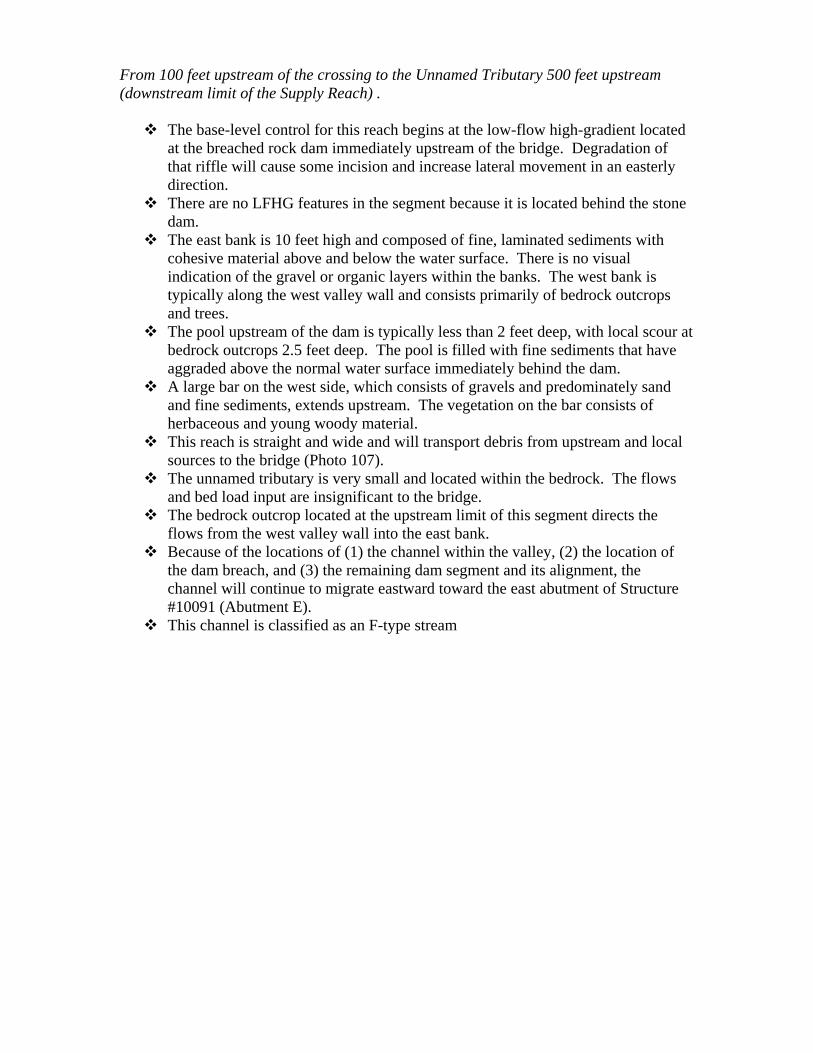
From 100 feet upstream of the crossing to the Unnamed Tributary 500 feet upstream (downstream limit of the Supply Reach) .
The base-level control for this reach begins at the low-flow high-gradient located at the breached rock dam immediately upstream of the bridge. Degradation of that riffle will cause some incision and increase lateral movement in an easterly direction. There are no LFHG features in the segment because it is located behind the stone
dam. The east bank is 10 feet high and composed of fine, laminated sediments with
cohesive material above and below the water surface. There is no visual indication of the gravel or organic layers within the banks. The west bank is typically along the west valley wall and consists primarily of bedrock outcrops and trees. The pool upstream of the dam is typically less than 2 feet deep, with local scour at
bedrock outcrops 2.5 feet deep. The pool is filled with fine sediments that have aggraded above the normal water surface immediately behind the dam. A large bar on the west side, which consists of gravels and predominately sand
and fine sediments, extends upstream. The vegetation on the bar consists of herbaceous and young woody material. This reach is straight and wide and will transport debris from upstream and local
sources to the bridge (Photo 107). The unnamed tributary is very small and located within the bedrock. The flows
and bed load input are insignificant to the bridge. The bedrock outcrop located at the upstream limit of this segment directs the
flows from the west valley wall into the east bank. Because of the locations of (1) the channel within the valley, (2) the location of
the dam breach, and (3) the remaining dam segment and its alignment, the channel will continue to migrate eastward toward the east abutment of Structure #10091 (Abutment E). This channel is classified as an F-type stream
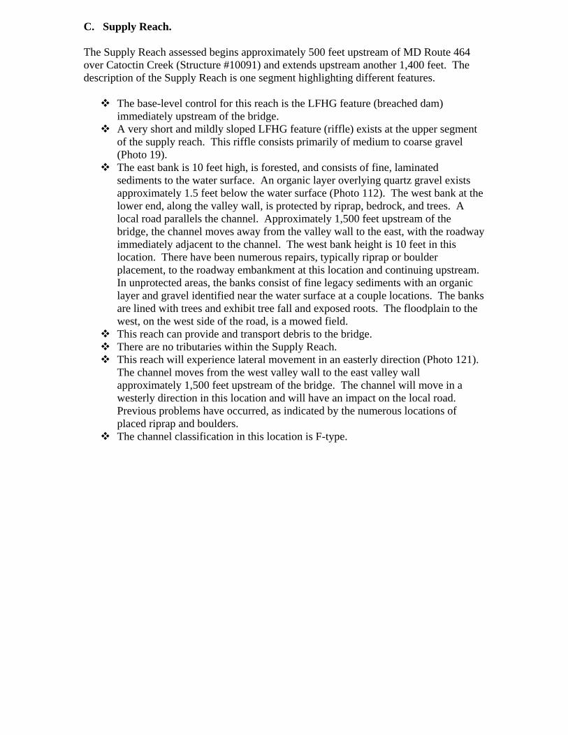
C. Supply Reach. The Supply Reach assessed begins approximately 500 feet upstream of MD Route 464 over Catoctin Creek (Structure #10091) and extends upstream another 1,400 feet. The description of the Supply Reach is one segment highlighting different features.
The base-level control for this reach is the LFHG feature (breached dam) immediately upstream of the bridge. A very short and mildly sloped LFHG feature (riffle) exists at the upper segment
of the supply reach. This riffle consists primarily of medium to coarse gravel (Photo 19). The east bank is 10 feet high, is forested, and consists of fine, laminated
sediments to the water surface. An organic layer overlying quartz gravel exists approximately 1.5 feet below the water surface (Photo 112). The west bank at the lower end, along the valley wall, is protected by riprap, bedrock, and trees. A local road parallels the channel. Approximately 1,500 feet upstream of the bridge, the channel moves away from the valley wall to the east, with the roadway immediately adjacent to the channel. The west bank height is 10 feet in this location. There have been numerous repairs, typically riprap or boulder placement, to the roadway embankment at this location and continuing upstream. In unprotected areas, the banks consist of fine legacy sediments with an organic layer and gravel identified near the water surface at a couple locations. The banks are lined with trees and exhibit tree fall and exposed roots. The floodplain to the west, on the west side of the road, is a mowed field. This reach can provide and transport debris to the bridge. There are no tributaries within the Supply Reach. This reach will experience lateral movement in an easterly direction (Photo 121).
The channel moves from the west valley wall to the east valley wall approximately 1,500 feet upstream of the bridge. The channel will move in a westerly direction in this location and will have an impact on the local road. Previous problems have occurred, as indicated by the numerous locations of placed riprap and boulders. The channel classification in this location is F-type.


![Welcome [parkcitygroup.actonsoftware.com]parkcitygroup.actonsoftware.com/acton/attachment... · HACCP or GFSI Food Safety Plans? § 117.330. To the extent that an existing HACCP plan](https://img.pdfslide.net/doc/110x75/5fcb47a5b4a414204d2e0891/welcome-haccp-or-gfsi-food-safety-plans-117330-to-the-extent-that-an-existing.jpg)