Embed Size (px)
Citation preview
1ATTACHMENT A4
TRAFFIC PATTERNS
1
2
Waste Isolation Pilot PlantHazardous Waste PermitMarch 2018
(This page intentionally blank)
1234
1

Waste Isolation Pilot PlantHazardous Waste Permit
March 2018
ATTACHMENT A4
TRAFFIC PATTERNSTABLE OF CONTENTS
A4-1 Traffic Information and Traffic Patterns..............................................................................1
A4-2 Facility Access and Traffic.................................................................................................1
A4-3 Waste Handling Building Traffic.........................................................................................3
A4-4 Underground Traffic...........................................................................................................4
PERMIT ATTACHMENT A4Page A4-i
1234
1
2
3
4
5
6
78

Waste Isolation Pilot PlantHazardous Waste PermitMarch 2018
LIST OF TABLES
Table Title
Table A4-1 Waste Isolation Pilot Plant Site Design Designation Traffic Parameters a
LIST OF FIGURES
Figure Title
Figure A4-1 General Location of the WIPP FacilityFigure A4-2 WIPP Traffic Flow DiagramFigure A4-2-NFB WIPP Traffic Flow Diagram with Building 416Figure A4-3 Waste Transport Routes in Waste Handling Building - Container Storage
UnitFigure A4-3a Typical Transport Route for TRUPACT-II and Standard Large Box 2Figure A4-3b Typical Transport Route for TRUPACT-II and Standard Large Box 2 in
Room 108Figure A4-4 Typical Underground Transport Route Using E-140Figure A4-4a Typical Underground Transport Route Using W-30Figure A4-5 RH Bay Waste Transport RoutesFigure A4-6 RH Bay Cask Loading Room Waste Transport RouteFigure A4-7 RH Bay Canister Transfer Cell Waste Transport Route
PERMIT ATTACHMENT A4Page A4-ii
1234
1
2
34
5
6
7891011121314151617181920
21

Waste Isolation Pilot PlantHazardous Waste Permit
March 2018
ATTACHMENT A4
TRAFFIC PATTERNA4-1 Traffic Information and Traffic Patterns
Access to the WIPP facility is provided by two access roads that connect with U.S. Highway 62/180, 13 mi (21 km) to the north, and NM Highway 128 (Jal Highway), 4 mi (6.4 km) to the south (Figure A4-1). These access roads were built for the Permittees to transport TRU mixed waste to the site. Both access roads are owned and maintained by the Department of Energy (DOE). Signs and pavement markings are located in accordance with the Uniform Traffic Control Devices Manual. Access-road design designation parameters, such as traffic volume, are presented in Table A4-1.
A4-2 Facility Access and Traffic
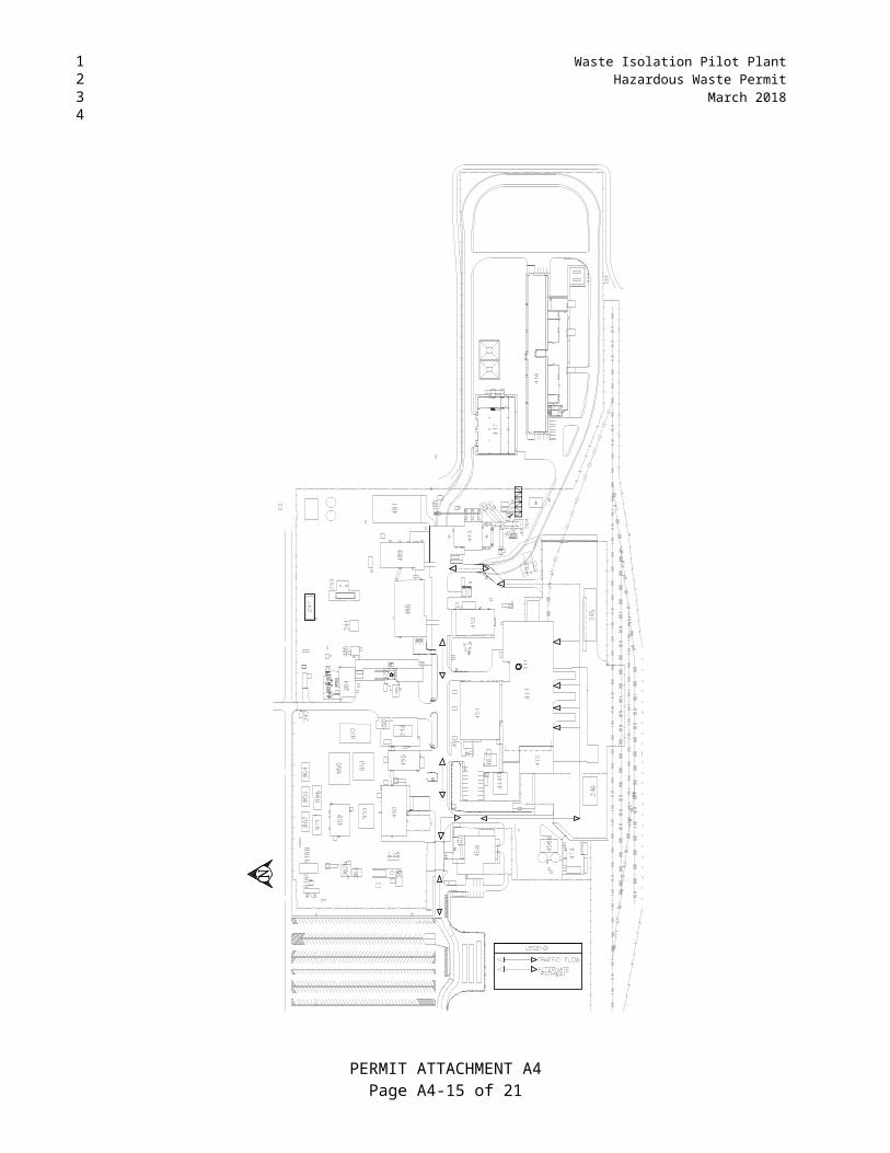
Access to the facility for personnel, visitors, and trucks carrying supplies and TRU mixed waste is provided through a security checkpoint (vehicle trap). After passing through the security checkpoint, TRU mixed waste transport trucks will normally turn right (south) before reaching the Support Building and then left (east) to park in the parking area HWMU just east of the air locks (Figure A4-2). Outgoing trucks depart the same way they arrived, normally out of the west end of the parking area, north through the fence gate and out through the vehicle trap. An alternate inbound route is to continue straight ahead from the security checkpoint to the second road and to turn south to enter the truck parking area. The alternate outbound route is also the reverse of this route. Salt transport trucks, which remove mined salt from the Salt Handling Shaft area, will not cross paths with TRU mixed waste transporters; instead, they will proceed from the Salt Handling Shaft northward to the salt pile. After passing through security, access for large equipment may be provided through the east gate. Figure A4-2 shows surface traffic flow at the WIPP facility.
The site speed limit for motor vehicles is 10 mph (16 kph) and 5 mph (8 kph) for rail movements. Speed limits are clearly posted at the entrance to the site and enforced by security officers. There are no traffic signals. Stop signs are located at the major intersections of roadways with the main east-west road. Safety requirements are communicated to all site personnel via General Employee Training within 30 days of their employment. Employee access to on-site facilities requires an annual refresher course to reinforce the safety requirements. Security officers monitor vehicular traffic for compliance with site restrictions, and provide instructions to off-site delivery shipments. Vehicular traffic other than the waste transporters use the same roads, but there will be no interference because there are two lanes available on the primary and alternate routes for waste shipments. Pedestrian traffic is limited to the sidewalks and prominently marked crosswalks. Site traffic is composed mostly of pickup trucks and electric carts with a frequency of perhaps 10 per hour at peak periods. Emergency vehicles are exercised periodically for maintenance and personnel training, with an average frequency of one each per day. They are used for their intended purpose on an as-required basis.
The traffic circulation system is designed in accordance with American Association of State Highway and Transportation Officials (AASHTO) Site Planning Guides for lane widths, lateral clearance to fixed objects, minimum pavement edge radii, and other geometric features. Objects in or near the roadway are prominently marked.
PERMIT ATTACHMENT A4Page A4-1 of 21
1234
1
2
3
45678910
11
12131415161718192021222324
2526272829303132333435363738
39404142

Waste Isolation Pilot PlantHazardous Waste PermitMarch 2018
On-site roads, sidewalks, and paved areas are used for the distribution and storage of vehicles and personnel and are designed to handle all traffic generated by employees, visitors, TRU mixed waste shipments, and movements of operational and maintenance vehicles. The facility entrance and TRU mixed waste haul roads are designed for AASHTO H20-S16 wheel loading. Service roads are designed for AASHTO H10 wheel loading. Access and on-site paved roads are designed to bear the anticipated maximum load of115,000 lbs (52,163.1 kg), the maximum allowable weight of a truck/trailer carrying loaded Contact-Handled or Remote-Handled Packages. The facility is designed to handle approximately eight truck trailers per day, each carrying one or more Contact-Handled or Remote-Handled Packages. This is equivalent to 3,640 TRU mixed waste-carrying vehicles per year.
The calculations to support the anticipated maximum load of 115,000 lbs. are shown below:
Soil Resistance R (psi) - is taken directly from the WIPP Soil Report and Bechtel calculation because there is no change.
A. Pavement Thickness
The traffic frequency increase from 10 shipments per day to 10.15 shipments per day has only minimal impact on the Total Expanded Average Load (EAL) and the traffic index (TI) as shown below, both important parameters in pavement design.
Total EAL (TEAL):13,780 ~ constant for 5 or more axles over 20 years, taken from Table 7-651.2A - Highway Design Manual (HDM).TEAL = 13,780 × 25yr./20yr. = 17,225Using 10.15 shipments per day ~ 17,225 × 10.15 = 174,834
Conversion of EAL to Traffic Index (TI).For TEAL of 174,834 ~ TI = 7.5 - (from HDM, Table 7-651.2B)
Asphalt Concrete Thickness TAC:GE = 0.0032 × TI × (100 -R)....R = 80GE - Gravel Equivalent (Ft).GE = 0.0032 × 7.5 × 20 = 0.48′ ...GfAC = 2.01 TAC = 0.48/2.01 = 0.24′ use 2½″ AC Surface Course.(Actually used: 3″)Gf - Gravel Equivalent Factor (constant from Table 7-651.2C from HDM).
B. Bituminous Treated Base
GE = 0.0032 × TI × (100 -R) .... R = 55 ~ caliche subbase GE = 1.08′ GEBTB = 1.08 - 2.01 × 0.21 = 0.66′TBTB = GEBTB/GfBTB = 0.66/1.2 = 0.55′ Use 4″ BTBGfBTB ~ taken from table 7-651.2C
C. Caliche Subbase ~ TCSB
GE = 0.0032 × TI × (100 -R) .....R = 50 - prepared subgradeGE = 1.2
PERMIT ATTACHMENT A4Page A4-2 of 21
1234
12345678910
11
1213
14
151617
1819202122
2324
25262728293031
32
33343536
37
3839

Waste Isolation Pilot PlantHazardous Waste Permit
March 2018
GECSB = 1.2 - (0.21× 2.07) - (0.33 × 1.2) 0.37′TCBS = 0.37/1.0 = 0.37′ ~ 4½″
Based on the results of the above calculation, the site paved roads designated for waste transportation are safe to be used by the heavier truckloads carrying shipping casks used in RH TRU mixed waste transportation to the WIPP.
A4-3 Waste Handling Building Traffic
CH TRU mixed waste will arrive by tractor-trailer at the WIPP facility in sealed Contact Handled Packages. Prior to unloading the packages from the trailer, security checks, radiological surveys, and shipping documentation reviews will be performed. A forklift or Yard Transfer Vehicle will remove the Contact Handled Packages and transport them a short distance through an air lock that is designed to maintain differential pressure in the WHB. The forklift or Yard Transfer Vehicle will place the shipping containers at one of the two TRUPACT-II unloading docks (TRUDOCK) inside the WHB or, in the case of the TRUPACT-III, at the payload transfer station in Room 108.
The TRUPACT-II may hold up to two 55-gallon drum seven-packs, two 85-gallon drum four-packs, two 100-gallon drum three-packs, two standard waste boxes (SWB), or one ten-drum overpack (TDOP). A HalfPACT may hold seven 55-gallon drums, one SWB, or four 85-gallon drums. The TRUPACT-III holds a single SLB2. A six-ton overhead bridge crane or Facility Transfer Vehicle with a transfer table will be used to remove the contents of the Contact Handled Package. Waste containers will be surveyed for radioactive contamination and decontaminated or returned to the Contact Handled Package as necessary.
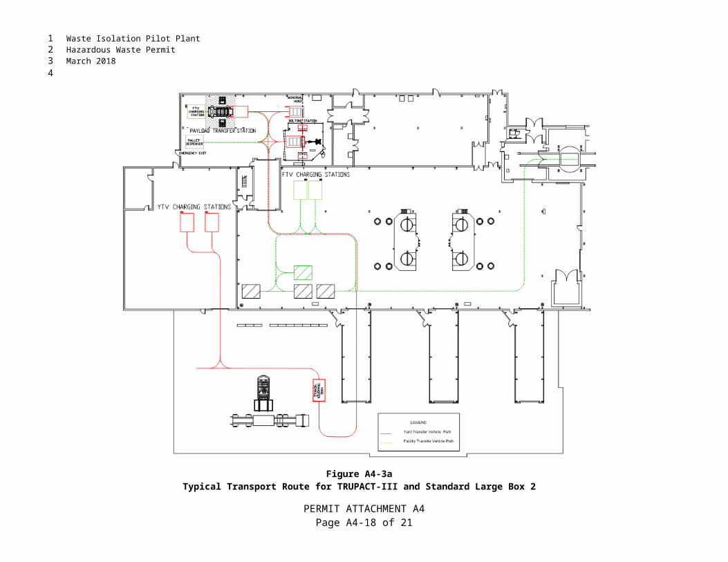
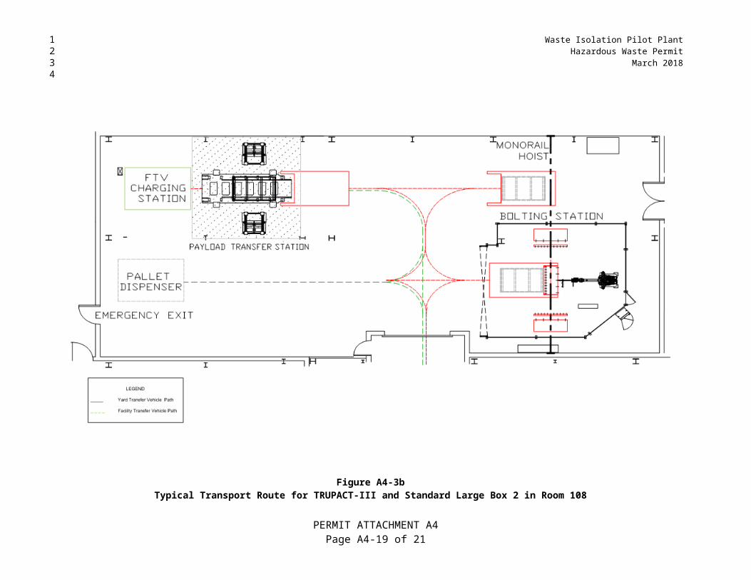
Each facility pallet will accommodate four 55-gallon drum seven-packs, four SWBs, four 85-gallon drum four-packs, four 100-gallon drum three-packs, two TDOPs, or an SLB2. Waste containers will be secured to the facility pallet prior to transfer. A forklift or facility transfer vehicle will transport the loaded facility pallet the air lock at the Waste Shaft (Figures A4-3, A4-3a, and A4-3b). The facility transfer vehicle will be driven onto the waste shaft conveyance deck, where the loaded facility pallet will be transferred to the waste shaft conveyance and downloaded for emplacement.
RH TRU mixed waste will arrive at the WIPP facility in a payload container contained in a shielded cask loaded on a tractor-trailer. Prior to unloading the cask from the trailer, radiological surveys, security checks, and shipping documentation reviews will be performed, and the trailer carrying the cask will be moved into the Parking Area or directly into the RH Bay of the Waste Handling Building Unit.
The cask is unloaded from the trailer in the RH Bay and is placed on the Cask Transfer Car. The Cask Transfer Car is used to move the cask to the Cask Unloading Room. At this point, a crane moves the waste to the Hot Cell or the Transfer Cell. Some RH TRU mixed waste may be moved to the Hot Cell for overpacking before being moved to the Transfer Cell. Once in the Transfer Cell, the Transfer Cell Shuttle Car moves the waste beneath the facility cask. A crane is used to move the waste from the Transfer Cell Shuttle Car into the facility cask. The Facility Cask Transfer Car then moves the facility cask to the underground. A more detailed description of waste handling in the WHB is included in Attachment A1. Figures A4-5, A4-6 and A4-7 show RH TRU mixed waste transport routes.
PERMIT ATTACHMENT A4Page A4-3 of 21
1234
12
345
6
7891011121314
15161718192021
22232425262728
2930313233
343536373839404142

Waste Isolation Pilot PlantHazardous Waste PermitMarch 2018
A4-4 Underground Traffic
The Permittees shall designate the traffic routes of TRU mixed waste handling equipment and construction equipment and record this designation on a map that is posted in a location where it can be examined by personnel entering the underground. The map will be updated whenever the routes are changed. Maps will be available in facility files until facility closure. The ventilation and traffic flow path in the TRU mixed waste handling areas underground are restricted and separate from those used for mining and haulage (construction) equipment, except that during waste transport in W-30, ventilation need not be separated north of S-1600 (Figures A4-4 and A4-4a). In general, the Permittees restrict waste traffic to the intake ventilation drift to maximize isolation of this activity from personnel. The exhaust drift in the waste disposal area will normally not be used for personnel access. Non-waste and non-construction traffic is generally comprised of escorted visitors only and is minimized during each of the respective operations.
Adequate clearances that exceed the mining regulations of 30 CFR §57 exist underground for safe passage of vehicles and pedestrians. Pedestrians/personnel are required to yield to vehicles in the WIPP underground facility. This condition is reinforced through the WIPP equipment operating procedures, the WIPP Safety Manual, the WIPP safety briefing required for all underground visitors, the General Employee Training annual refresher course, and the Underground annual refresher course that are mandated by 30 CFR §57, the New Mexico Mine Code, and DOE Order 5480.20A.
In addition, other physical means are utilized to safeguard pedestrians/personnel when underground such as:
All equipment operators are required to sound the vehicle horn when approaching intersections.
All airlock and bulkhead vehicle doors are equipped with warning bells or strobe lights to alert personnel when door opening is imminent.
Hemispherical mirrors are used at blind intersections so that persons can see around corners.
All heavy equipment is required to have operational back-up alarms.
Heavily used intersections are well lighted.
Typically, the traffic routes during waste disposal in all Panels will use the same main access drifts.
All traffic safety is regulated and enforced by the Federal and State mine codes of regulations (30 CFR §57 and New Mexico State Mine Code). The agencies that administer these codes make regular inspection tours of the WIPP underground facilities for the purpose of enforcement.
All underground equipment is designed for off-road use since all driving surfaces are excavated in salt. No loads on the underground roadways will exceed the bearing strength of in situ halite.
PERMIT ATTACHMENT A4Page A4-4 of 21
1234
1
23456789101112
13141516171819
2021
2223
2425
2627
28
29
3031
32333435
3637

Waste Isolation Pilot PlantHazardous Waste Permit
March 2018
TABLES
PERMIT ATTACHMENT A4Page A4-5 of 21
1234
1

Waste Isolation Pilot PlantHazardous Waste PermitMarch 2018
(This page intentionally blank)
PERMIT ATTACHMENT A4Page A4-6 of 21
1234
1

Waste Isolation Pilot PlantHazardous Waste Permit
March 2018
Table A4-1Waste Isolation Pilot Plant Site Design Designation Traffic Parameters a
Traffic Parameter
North Access Road (No. of Vehicles, unless otherwise
stated)
South Access Road (No. of Vehicles, unless otherwise
stated)
On-Site Waste Haul Roads Contact-Handled and
Remote-Handled Package Traffic)
Average Daily Traffic (ADT)b 800 800 8
Design Hourly Volume (DHV)c 144 144 NA g
Hourly Volume(Max. at Shift Change)
250 250 NA
Distribution (D)d 67% 67% NA
Trucks (T)e 2% 2% 100%
Design Speed h ,i 70 mph (113 kph) 60 mph (97 kph) 25 mph (40 kph)
Control of Access f None None Fulla For WIPP personnel and TRU mixed waste shipments only.b ADT—Estimated number of vehicles traveling in both directions per day.c DHV—A two-way traffic count with directional distribution.d D—The percentage of DHV in the predominant direction of travel.e T—The percentage of ADT comprised of trucks (excluding light delivery trucks).f Control of Access—The extent of roadside interference or restriction of movement.g NA—Not applicable.h mph—miles per hour.i kph—kilometers per hour.
PERMIT ATTACHMENT A4Page A4-7 of 21
1234
12

Waste Isolation Pilot PlantHazardous Waste PermitMarch 2018
(This page intentionally blank)
PERMIT ATTACHMENT A4Page A4-8 of 21
1234
1

Waste Isolation Pilot PlantHazardous Waste Permit
March 2018
FIGURES
PERMIT ATTACHMENT A4Page A4-9 of 21
1234
1

Waste Isolation Pilot PlantHazardous Waste PermitMarch 2018
(This page intentionally blank)
PERMIT ATTACHMENT A4Page A4-10 of 21
1234
1

Waste Isolation Pilot PlantHazardous Waste Permit
March 2018
Figure A4-1General Location of the WIPP Facility
PERMIT ATTACHMENT A4Page A4-11 of 21
1234

Waste Isolation Pilot PlantHazardous Waste PermitMarch 2018
Figure A4-2WIPP Traffic Flow Diagram
PERMIT ATTACHMENT A4Page A4-12 of 21
1234

Waste Isolation Pilot PlantHazardous Waste Permit
March 2018
Figure A4-2-NFBWIPP Traffic Flow Diagram with Building 416
PERMIT ATTACHMENT A4Page A4-13 of 21
1234

Waste Isolation Pilot PlantHazardous Waste PermitMarch 2018
Figure A4-3Waste Transport Routes in Waste Handling Building - Container Storage Unit
PERMIT ATTACHMENT A4Page A4-14 of 21
1234
Waste Isolation Pilot PlantHazardous Waste Permit
March 2018
Figure A4-3aTypical Transport Route for TRUPACT-III and Standard Large Box 2
PERMIT ATTACHMENT A4Page A4-15 of 21
1234

Waste Isolation Pilot PlantHazardous Waste PermitMarch 2018
Figure A4-3bTypical Transport Route for TRUPACT-III and Standard Large Box 2 in Room 108
PERMIT ATTACHMENT A4Page A4-16 of 21
1234

Waste Isolation Pilot PlantHazardous Waste Permit
March 2018
Figure A4-4Typical Underground Transport Route Using E-140
PERMIT ATTACHMENT A4Page A4-17 of 21
1234
Waste Isolation Pilot PlantHazardous Waste PermitMarch 2018
Figure A4-4aTypical Underground Transport Route Using W-30
PERMIT ATTACHMENT A4Page A4-18 of 21
1234
Waste Isolation Pilot PlantHazardous Waste Permit
March 2018
Figure A4-5RH Bay Waste Transport Routes
PERMIT ATTACHMENT A4Page A4-19 of 21
1234

Waste Isolation Pilot PlantHazardous Waste PermitMarch 2018
Figure A4-6RH Bay Cask Loading Room Waste Transport Route
PERMIT ATTACHMENT A4Page A4-20 of 21
1234

Waste Isolation Pilot PlantHazardous Waste Permit
March 2018
Figure A4-7RH Bay Canister Transfer Cell Waste Transport Route
1
PERMIT ATTACHMENT A4Page A4-21 of 21
1234