Embed Size (px)
Citation preview

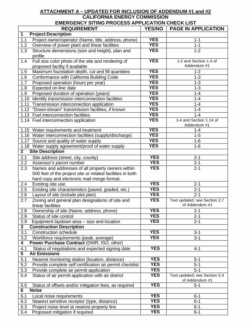
ATTACHMENT A – UPDATED FOR INCLUSION OF ADDENDUM #1 and #2 CALIFORNIA ENERGY COMMISSION
EMERGENCY SITING PROCESS APPLICATION CHECK LIST REQUIREMENT YES/NO PAGE IN APPLICATION
1 Project Description 1.1 Project owner/operator (Name, title, address, phone) YES 1-1 1.2 Overview of power plant and linear facilities YES 1-1 1.3 Structure demensions (size and height), plan and
profile YES 1-2
1.4 Full size color photo of the site and rendering of proposed facility if available
YES 1-2 and Section 1.4 of Addendum #1
1.5 Maximum foundation depth, cut and fill quantities YES 1-2 1.6 Conformance with California Building Code YES 1-3 1.7 Proposed operation (hours per year) YES 1-3 1.8 Expected on-line date YES 1-3 1.9 Proposed duration of operation (years) YES 1-4 1.10 Identify transmission interconnection facilities YES 1-4 1.11 Transmission interconnection application YES 1-4 1.12 “Down-stream” transmission facilities, if known YES 1-4 1.13 Fuel interconnection facilities YES 1-4 1.14 Fuel interconnection application YES 1-4 and Section 1.14 of
Addendum #1 1.15 Water requirements and treatment YES 1-4 1.16 Water interconnection facilities (supply/discharge) YES 1-5 1.17 Source and quality of water supply YES 1-6 1.18 Water supply agreement/proof of water supply YES 1-6 2 Site Description 2.1 Site address (street, city, county) YES 2-1 2.2 Assessor’s parcel number YES 2-1 2.3 Names and addresses of all property owners within
500 feet of the project site or related facilities in both hard copy and electronic mail merge format.
YES 2-1
2.4 Existing site use YES 2-1 2.5 Existing site characteristics (paved, graded, etc.) YES 2-1 2.6 Layout of site (include plot plan) YES 2-1 2.7 Zoning and general plan designations of site and
linear facilities YES Text updated; see Section 2.7
of Addendum #1
2.8 Ownership of site (Name, address, phone) YES 2-1 2.9 Status of site control YES 2-1 2.9 Equipment laydown area – size and location YES 2-1 3 Construction Description 3.1 Construction schedule YES 3-1 3.2 Workforce requirements (peak, average) YES 3-1 4 Power Purchase Contract (DWR, ISO, other) 4.1 Status of negotiations and expected signing date YES 4-1 5 Air Emissions 5.1 Nearest monitoring station (location, distance) YES 5-1 5.2 Provide complete self certification air permit checklist YES 5-1 5.3 Provide complete air permit application YES 5-1 5.4 Status of air permit application with air district YES Text updated; see Section 5.4
of Addendum #1 5.5 Status of offsets and/or mitigation fees, as required YES 5-1 6 Noise 6.1 Local noise requirements YES 6-1 6.2 Nearest sensitive receptor (type, distance) YES 6-1 6.3 Project noise level at nearest property line YES 6-1 6.4 Proposed mitigation if required YES 6-1

REQUIREMENT YES/NO PAGE IN APPLICATION 7 Hazardous Materials 7.1 Type and volume of hazardous materials on-site YES 7-1 and Section 7.1/7.2 of
Addendum #2 7.2 Storage facilities and containment YES 7-1 and Section 7.1/7.2 of
Addendum #2 8 Biological resources 8.1 Legally protected species* and their habitat on site,
adjacent to site and along right of way for linear facilities (*threatened or endangered species on State or federal lists, State fully protected species)
YES 8-1
8.2 Designated critical habitat on site or adjacent to site (wetlands, vernal pools, riparian habitat, preserves)
YES 8-1
8.4 Proposed mitigation as required YES 8-1 9 Land Use 9.1 Local land use restrictions (height, use, etc.) YES Text updated; see Section 9.1
of Addendum #1 9.2 Use of adjacent parcels (include map) YES 9-1 9.3 Ownership of adjacent parcels – site and linears YES 9-1 9.4 Demographics of census tract where project is
located (most current available) YES 9-1
10 Public Services 10.1 Ability to serve letter from Fire District YES 10-1 10.2 Nearest fire station YES 10-1 11 Traffic and Transportation 11.1 Level of Service (LOS) measurements on
surrounding roads – a.m. and p.m. peaks YES 11-1
11.2 Traffic Control Plan for roads during construction YES 11-1 11.3 Traffic impact of linear facility construction YES 11-1 11.4 Equipment transport route YES 11-1 11.5 Parking requirements – workforce and equipment YES 11-1 12 Soils and Water Resources 12.1 Wastewater volume, quality, treatment YES 12-1 12.2 Status of permits for wastewater discharge or draft
permit (WDR/NPDES) YES 12-2
12.3 Draft Erosion Prevention and Sedimentation Control Plan or Mitigation Strategy
YES 12-3 and Section 12.3 of Addendum #1
12.4 Spill Prevention/Water Quality Protection Plans YES 12-3, Section 12.4 of Addendum #1, Updated in
Section 12.4 of Addendum #2 13 Cultural Resources 13.1 Identification of known historic/prehistoric sites YES 13-1 13.2 Proposed mitigation if required YES 13-1 13.3 Notification of Native Americans YES 13-1 14 Paleontological Resources 14.1 Identification of known paleontologic sites YES 14-1 14.2 Proposed mitigation if required YES 14-1 15 Visual resources 15.1 Plan for landscaping and screening to meet local
requirements YES 15-1
15.2 Full size color photo of the site and rendering of proposed facility with any proposed visual mitigation if available
YES 15-1
16 Transmission System Engineering 16.1 Conformance with Title 8, High Voltage Electrical
Safety Orders, CPUC General Order 95 (or NESC), CPUC Rule 21, PTO Interconnection Requirements, and National Electric Code
YES 16-1

7.1 Type and volume of hazardous materials onsite 7.2 Storage facilities and containment This section includes supplemental information requested by the CEC. No text changes were made to Sections 7.1 or 7.2 of the May 11, 2001 CEC Application.

Spill Prevention, Control,
And Countermeasure (SPCC) Plan
For:
PG&E Dispersed Generating LLC 3497 Main Street
Chula Vista, Ca 91911 Chula Vista Site Control Room
Facility Contact: Thomas Coleman (619)-420-3291
May 21, 2001

TABLE OF CONTENTS (I) Executive Summary (II) Oil Spill Regulations and the SPCC (III) The SPCC Plan (IV) Professional Engineer Certification - 40 CFR 112.3 1.0 SPCC PLAN REVIEW - 40 CFR 112.5(b) 2.0 MANAGEMENT APPROVAL - 40 CFR 112.7 3.0 PAST CMSD SPILL HISTORY - 40 CFR 112.7(a) 4.0 FACILITY GENERAL INFORMATION - 40 CFR 112.7 5.0 POTENTIAL SPILL VOLUMES AND RATES - 40 CFR 112.7(b) 6.0 CONTAINMENT AND DIVERSIONARY STRUCTURES- 40 CFR 112.7(c)(1) 7.0 DEMONSTRATION OF PRACTICABILITY - 40 CFR 112.7(d) 8.0 FACILITY DRAINAGE - 40 CFR 112.7(e)(1) 9.0 BULK STORAGE TANKS - 40 CFR 112.7(e)(2) 10.0 TRANSFER OPERATIONS AND PROCESSES - 40 CFR 112.7(e)(3) 11.0 TRUCK LOADING/UNLOADING - 40 CFR 112.7(e)(4) 12.0 INSPECTION AND RECORDS - 40 CFR 112.7(e)(8) 13.0 SECURITY - 40 CFR 112.7(e)(9) 14.0 TRAINING AND SPILL PREVENTION PROCEDURES - 40 CFR 112.7(e)(10)

LIST OF ATTACHMENTS Attachment #1 Facility Diagrams (Site Location Plan, Facility Layout Plan, and Surface
Drainage Direction and Storm Drain Locations) Attachment #2 Oil Spill Contingency Plan Attachment #3 Certification of Applicability Form Attachment #4 Evacuation Plan Attachment #5 First Responder Forms Attachment #6 Response and Clean-up Form Attachment #7 Spill Reporting Numbers Attachment #8 SPCC Decision Analysis

PG&E-DG – SPCC Plan
Page #1
(I) Executive Summary This Spill Prevention Control and Countermeasure (SPCC) Plan is one of many plans and procedures at PG&E-DG designed to prevent and/or minimize pollution. This plan is not developed as a stand-alone document. All procedures and practices described in this plan are intended to complement other plans and procedures developed for other regulatory programs. For example, several Best Management Practices (BMP’s) in the Storm Water Pollution Prevention Plan (SWPPP) are specifically related to oil pollution prevention. This document does not attempt to duplicate practices laid out in other plans. This plan is intended to meet the requirements outlined in 40 CFR 112.7. For a more complete understanding of PG&E-DG’s practices and procedures designed to prevent pollution and respond to spills, consult the following documents: • Storm Water Pollution Prevention Practice Plan (SWPPP) • Risk Management Plan (RMP) • Hazardous Materials Business Plan (Business Plan) (II) Oil Spill Regulations and the SPCC Spills of oils, related petroleum products, and other hazardous substances into surface waters, sanitary sewer systems, or storm sewer systems, present potentially serious environmental, and human health hazards that must be prevented and controlled. In the event that spills occur, timely and efficient countermeasures must be initiated to contain and recover these substances in order to mitigate adverse effects. The US Congress initially set up the legislative framework to address oil spill events with the 1970 Water Quality Improvement Act, which established reporting obligations and a prohibition on the discharge of harmful quantities of oil (i.e., those which caused a sheen on the water). With the passage of the Federal Water Pollution Control Act of 1972, more commonly known as the Clean Water Act (CWA), the 1970 Water Quality Improvement Act was updated and restrictions on the discharge of hazardous substances were added. In 1990, Congress passed the Oil Pollution Act (OPA) in response to the Exxon Valdez spill. OPA, in part, amended the CWA by strengthening the oil spill provisions to include more stringent reporting and cleanup requirements and more severe penalties for discharges. The Environmental Protection Agency (EPA) and the United States Coast Guard (USCG) are the two main Federal agencies that address and regulate facilities that handle, transfer and store oil and petroleum products. Both agencies have promulgated certain requirements, which when appropriately implemented by facilities, enable the facilities to prevent, control, respond, and mitigate discharges. The USCG and the Department of Transportation (DOT) have regulatory jurisdiction authority over the fuel and oil transportation-related facilities and operations, while the Environmental Protection Agency (EPA) regulates non-transportation related facilities and operations. Tank trucks transporting fuel to a facility are engaged in interstate commerce, the unloading of this fuel is under the jurisdiction of the DOT. If the fuel or oil is being transferred to or from a ship or barge, the operation is under the jurisdiction of the USCG. All pipelines from a storage facility are under the jurisdiction of the DOT, Office of Pipeline

PG&E-DG – SPCC Plan
Page #2
Safety, unless the pipeline transfer is to a vessel, which is under the USCG jurisdiction. All other storage and handling of oil within the facility is under the authority of the EPA. (III) The SPCC Plan The intention of a Spill Prevention, Control and Countermeasures (SPCC) Plan is to establish the procedures and equipment required to prevent the discharge of oil and hazardous substances in harmful quantities. The Plan also establishes the activities required to mitigate discharges, should they occur. In accordance with 40 CRF 112.7, this plan addresses the following subject areas: • Certification of the plan by a registered professional engineer • Documentation of required reviews of plan • Written facility management approval • Oil spill history with brief descriptions of corrective and preventive actions • Facility location, description, and contact information • Diagram/layout of facility • Spill prediction flow direction, rate of flow, and maximum quantities • Description of drainage, containment, and diversionary structures • Description of bulk storage tanks and a description of transfer operations • Inspections and records discussion • Description of facility/operations security • Description of personnel training and spill prevention procedures • Certification of Substantial Harm Determination Form (IV) Professional Engineer Certification - 40 CFR 112.3
PROFESSIONAL ENGINEER CERTIFICATION PE CERTIFICATION STATEMENT: I hereby certify that I have examined the facility, and, being familiar with the provisions of 40 CFR Part 112, attest that this SPCC Plan has been prepared in accordance with good engineering practices. REGISTERED PROFESSIONAL: ENGINEER: Zachary F. Jacobs P.E. REA SIGNATURE: ____________________________________ REGISTRATION NUMBER: M 29154 STATE: California DATE: 05/21/01

PG&E-DG – SPCC Plan
Page #3
1.0 FACILITY GENERAL INFORMATION - 40 CFR 112.7 1. FACILITY NAME: Chula Vista Peak Power Generating Plant 2. TYPE OF FACILITY: Natural Gas Turbine Electric Generation Peaking Power Plant 3. LOCATION OF FACILITY:
3497 Main Street Chula Vista, Ca 91911 Chula Vista Site Control Room (619)420-3291
4. NAME AND ADDRESS OF OWNER/OPERATOR: PG&E Generating Company, LLC 345 California Street San Francisco, CA 94104 (415) 288-5678
5. DESIGNATED PERSON ACCOUNTABLE FOR OIL SPILL AT THE FACILITY: Thomas Coleman, Power Plant Operations Manager
(570) 449-4606 Cell (619) 498-0126 Job Trailer Chula Vista Site Control Room (619) 420-3291 Other Contacts: Steve Shorts-OPS- (619) 227-4177 Ken Boykin - OPS- (856) 261-8149 Bill Jolly (301) 706-7504 Cell Environmental Betty Kutsky - (301) 280-6949 Anne Volgemar (301) 280-6800 Greg Filippelli (301) 280-6800 Catherine McDavid (805) 898-1895 or (301)-280-6878 Safety and Health Rich Stephens (301) 280-6438 Beverly Larson (301) 280-6800
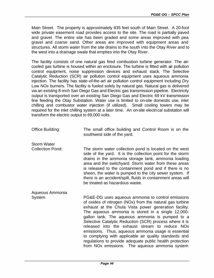
6. FACILITY DESCRIPTION: The power plant is located at 3497 Main Street in the City of Chula Vista, CA. The
property consists of one legal parcel (APN 629-062-04-00) that has no frontage on
PG&E-DG – SPCC Plan
Page #4
Main Street. The property is approximately 835 feet south of Main Street. A 20-foot wide private easement road provides access to the site. The road is partially paved and gravel. The entire site has been graded and some areas improved with pea gravel and coarse sand. Other areas are improved with equipment areas and structures. All storm water from the site drains to the south into the Otay River and to the west into a drainage swale that empties into the Otay River.
The facility consists of one natural gas fired combustion turbine generator. The air-
cooled gas turbine is housed within an enclosure. The turbine is fitted with air pollution control equipment, noise suppression devices and exhaust stack. The Selective Catalytic Reduction (SCR) air pollution control equipment uses aqueous ammonia injection. The facility has state-of-the-art air pollution control equipment including Dry Low NOx burners. The facility is fueled solely by natural gas. Natural gas is delivered via an existing 8-inch San Diego Gas and Electric gas transmission pipeline. Electricity output is transported over an existing San Diego Gas and Electric 69 kV transmission line feeding the Otay Substation. Water use is limited to on-site domestic use, inlet chilling and combustor water injection (if utilized). Small cooling towers may be required for the inlet chilling system at a later time. An on-site electrical substation will transform the electric output to 69,000 volts.
Office Building: The small office building and Control Room is on the southwest side of the yard.
Storm Water Collection Pond: The storm water collection pond is located on the west
side of the yard. It is the collection point for the storm drains in the ammonia storage tank, ammonia loading area and the switchyard. Storm water from these areas is released to the containment pond and if there is no sheen, the water is pumped to the city sewer system. If there is an accident/spill, fluids in containment areas will be treated as hazardous waste.
Aqueous Ammonia System PG&E-DG uses aqueous ammonia to control emissions
of oxides of nitrogen (NOx) from the natural gas turbine exhaust at the Chula Vista power generation facility. The aqueous ammonia is stored in a single 12,000-gallon tank. The aqueous ammonia is pumped to a Selective Catalytic Reduction (SCR) process where it is released into the exhaust stream to reduce NOx emissions. Thus, aqueous ammonia usage is essential to complying with applicable air quality standards and regulations to provide adequate public health protection from NOx emissions. The aqueous ammonia system

PG&E-DG – SPCC Plan
Page #5
will only be pressurized when the turbine operates, which is estimated to be less than 5,000 hours per year.
Ammonia at normal temperatures and pressures is a
colorless gas made up of one part nitrogen and three parts hydrogen (NH3). It is lighter than air and has a sharp pungent odor that serves as a warning of its presence. Although ammonia is a relatively toxic substance, it is not a cumulative poison. It is highly soluble in water and forms a solution known as ammonium hydroxide, which is commonly used as a household cleaner. The Department of Transportation (DOT) classifies aqueous ammonia as a nonflammable liquid.
Switchyard: The switchyard contains oil-filled electrical equipment.
The equipment is classified as non-PCB containing. The transformer contains approximately 5,500 gallons of mineral oil.
Yard Enclosure: The plant yard is protected by an eight-foot high chain-
link fence with slats. Fences and gates have barbed wire for additional security.
7. ADJACENT PROPERTY USE
The properties to the north and east are occupied by auto storage and wrecking yards. The property to the west is currently vacant, but was previously used as a trailer storage yard. A single-family home residential area is located across the vacant lot to the west. The surrounding area south of Main Street is characterized by similar auto storage and dismantling activities. The Otay River Valley is located along the property’s southern boundary.
8. OPERATING SCHEDULE:
The Chula Vista Power Generating Plant functions to provide peak power and emergency power. It feeds power to the SDG&E grid. It can be operated directly from the power control office that is located at the site. The facility is currently manned with a permanent operator. However, remote operation will commence in the future. The plant will operate on an “as needed” basis, and will provide power during the peak demand hours of the summer months.
9. OIL SPILL HISTORY: There have not been any oil spills at Chula Vista Peak Power Generating Plant.

PG&E-DG – SPCC Plan
Page #6
10. INVENTORY AND SPILL POTENTIAL: The inventory of oil-filled equipment and spill prevention data is presented below. The oil-filled equipment spill prevention techniques currently utilized and the potential for oil spills is discussed in this section.
The electric generators and the turbine engines have oil reservoirs for lubrication. The reservoirs and associated piping are contained within the engine compartments. The floors of the building have trench and floor drains to divert any oil releases into sump and then are cleaned up and disposed. The substation is equipped with energized oil-filled transformers and circuit breakers. The highest potential for spillage associated with this operating equipment would result from a casing rupture. The largest potential leakage from any single piece of equipment in the yard is 5,576 gallons. The Contingency Plan describes the emergency response for investigation, containment, and cleanup of oil releases.
11. CONTAINMENT STRUCTURES AND EQUIPMENT: All oil and hazardous materials are located in areas with secondary containment that
will hold in excess 110% of the largest container. This ensures that if there is a tank or case failure, oil spill will not reach navigable water.
12. FACILITY ADDITIONS:
The existing facility is adequate for containing an oil spill. No additional improvements are required at this time.
13. FLOODPLAIN: The Federal Emergency Management Administration (FEMA) floodplain maps show
the site as being within a 100-year floodplain. However, the maps were prepared prior to the filling of the site that occurred several years ago. The FEMA maps indicate the 100-year floodplain level at the site is 44 feet Above Mean Sea Level (AMSL). However, the site has been filled to a minimum elevation of 55 feet AMSL. Thus, the site is 10 to 11 feet above the 100-year floodplain level.
14. ENVIONMENTAL COMPLIANCE: The facility is designed to be compliant with all governing local, State and Federal
Law and Regulations, including but not limited to the Chula Vista industrial zone codes, Air Pollution Control permits, Department of Environmental Health permits, and local fire department requirements. Storm water pollution prevention is addressed through compliance with the General Permit and site-specific SWPPP.

PG&E-DG – SPCC Plan
Page #7
2.0 SPCC PLAN REVIEW - 40 CFR 112.5(b) To keep the SPCC Plan up to date, the regulations identify circumstances that require review and potential amendments. In accordance with 40 CFR 112, PG&E-DG is required to amend the SPCC Plan for the following reasons: • Amendments may be required by the Environmental Protection Agency (EPA) after
review of the SPCC Plan, submitted because of a spill event. • A review is required and amendments may be necessary whenever there is a change
in facility design, construction, operation, or maintenance that materially affects the potential for an oil spill.
• A review is required every three years. Amendments to the plan must be made if the review of the plan indicates that more effective control and prevention technology will significantly reduce the likelihood of a spill event.
EPA Reporting and Plan Amendments PG&E-DG must submit the PG&E-DG SPCC Plan and any amendments to the EPA (Region 9) when: • A discharge of more than 1,000 gallons (approximately 24 barrels) of oil into navigable
waters in a single spill event occurs; or • A discharge of oil in harmful quantities, as defined in 40 CFR part 110, occurs into
navigable waters in two reportable spill events within any 12-month period, which is regulated by this plan.
Within 60 days of the occurrence of either of these two conditions, PG&E-DG Chula Vista Operator will submit to EPA (Region 9) the following: • Name of the facility, owner or operator. • Location of the facility. • Maximum storage or handling capacity of the facility. • Description of the facility, including maps, flow diagrams, and topographical maps. • Complete copy of PG&E-DG SPCC Plan with any amendments. • The cause of such spill, including a failure analysis of the system or subsystem in
which the failure occurred. The failure analysis is to examine and explain the reason for the failure resulting in the spill event. The analysis should be explicit, definitive, and not general. Detailed analysis of the failure should be submitted concerning the nature of the failure that caused the spill.
• Supply corrective actions and/or countermeasures taken, including an adequate description of equipment repairs and/or replacements.
• Additional prevention measures taken or contemplated to minimize the possibility of recurrence.
• Other information as the EPA (Region 9) may require. Facility Modification Review and Amendment PG&E-DG is required to amend this SPCC Plan to reflect changes in facility design, construction, operation, or maintenance, which materially affects the potential for an oil

PG&E-DG – SPCC Plan
Page #8
spill. This change could be either the result of construction of a new facility or modification to an existing facility. The Chula Vista Operator is responsible for reviewing all plans for new construction, maintenance, or remodeling, to determine if amendments of the PG&E-DG SPCC Plan are required. If the plan must be amended, an environmental engineer will be responsible for having the plan amended and see that the amendments are implemented as soon as possible but no later than six months after the changes in design, construction, operation or maintenance occurred. Three year Review and Amendment PG&E-DG Environmental Systems is required to review and evaluate the PG&E-DG SPCC Plan at least every three years. This review must include an assessment of new technology that has become available for the prevention of spills since the plan was last reviewed. A complete facility inspection must be performed to verify compliance with the SPCC Plan and confirmation that all past recommendations have been implemented. Evidence of SPCC Review and Amendment All SPCC Plan amendments and reviews, except those proposed by EPA, will be certified by a registered Professional Engineer. Evidence of these reviews and applicable certifications is recorded in the table below. Administrative modifications should be made, as appropriate, to ensure the accuracy of plan information in response to modifications in the assignment of personnel or contact information (i.e., telephone numbers). PG&E-DG Chula Vista Operator will be responsible for keeping the definitive copy of this plan and all amendments. Date Reason For
Review Amendments PG&E-DG Environmental
Manager and Professional Engineer

PG&E-DG – SPCC Plan
Page #9
3.0 MANAGEMENT APPROVAL CERTIFICATION - 40 CFR 112.7 I have reviewed this plan and certify in accordance with 40 CFR 112.7 that the procedures and practices in the plan are combined with a solid management commitment to provide all the necessary funds and manpower to fully implement the plan as it is described in this document within six months. Name: _________________________________ Title: __________________________________ Signature: ______________________________ Date: ________ Note: This must be signed by management at a level with authority to commit the necessary resources.
PG&E-DG – SPCC Plan
Page #10
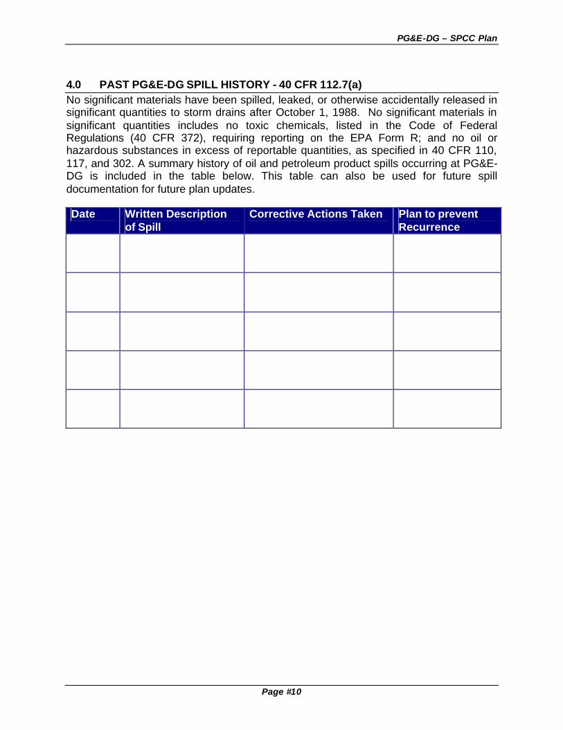
4.0 PAST PG&E-DG SPILL HISTORY - 40 CFR 112.7(a) No significant materials have been spilled, leaked, or otherwise accidentally released in significant quantities to storm drains after October 1, 1988. No significant materials in significant quantities includes no toxic chemicals, listed in the Code of Federal Regulations (40 CFR 372), requiring reporting on the EPA Form R; and no oil or hazardous substances in excess of reportable quantities, as specified in 40 CFR 110, 117, and 302. A summary history of oil and petroleum product spills occurring at PG&E-DG is included in the table below. This table can also be used for future spill documentation for future plan updates. Date Written Description
of Spill Corrective Actions Taken Plan to prevent
Recurrence

PG&E-DG – SPCC Plan
Page #11
5.0 POTENTIAL SPILL VOLUMES AND RATES - 40 CFR 112.7(b) Where experience indicates a reasonable potential for equipment failure (such as tank overflow, rupture, or leakage), the table below includes a prediction of the direction, rate of flow, and total quantity of hazardous substance that could be discharged from the facility as a result of each major type of failure. This information is summarized in the following table: Source Possible Quantity Released Direction of Flow Rate
of Flow
Ammonia Tank
This is the worst case scenario where a seam splits in a tank and the tank is full. Therefore the quantity of release would be the entire tank volume of 1,000 to 22,000 gallons.
Assuming a complete failure of the secondary containment, the direction would be to the nearest storm drain.
400 gpm
Ammonia Tank Overfill
Since all of PG&E-DG’s transfer operations are fully manned, the volume of spill will be minimized. It is predicted that a maximum overflow would be about 500 gallons.
If secondary containment fails, flow would be directed towards storm drains.
Pump Rate 80 to 100 gpm
Transformer Oils
5,500 gallons of mineral oils contained in the transformers could be released if the case is ruptured.
If secondary containment fails, flow would be directed towards storm drains.
400 gpm
Leaking Generator
Lubricating oils could leak slowly into containment areas. This could be due to many variables that are addressed in the preventive maintenance plan.
These systems have built in containment. Loss to the environment is highly unlikely
Minor rates of flow
Leaking Pipe or valves
If piping systems leak during a pumping operation, a 100-gallon discharge is predicted as a maximum.
Flow direction to the bay if secondary containment fails and/or piping is directly over water.
Minor rates of flow
PG&E-DG – SPCC Plan
Page #12
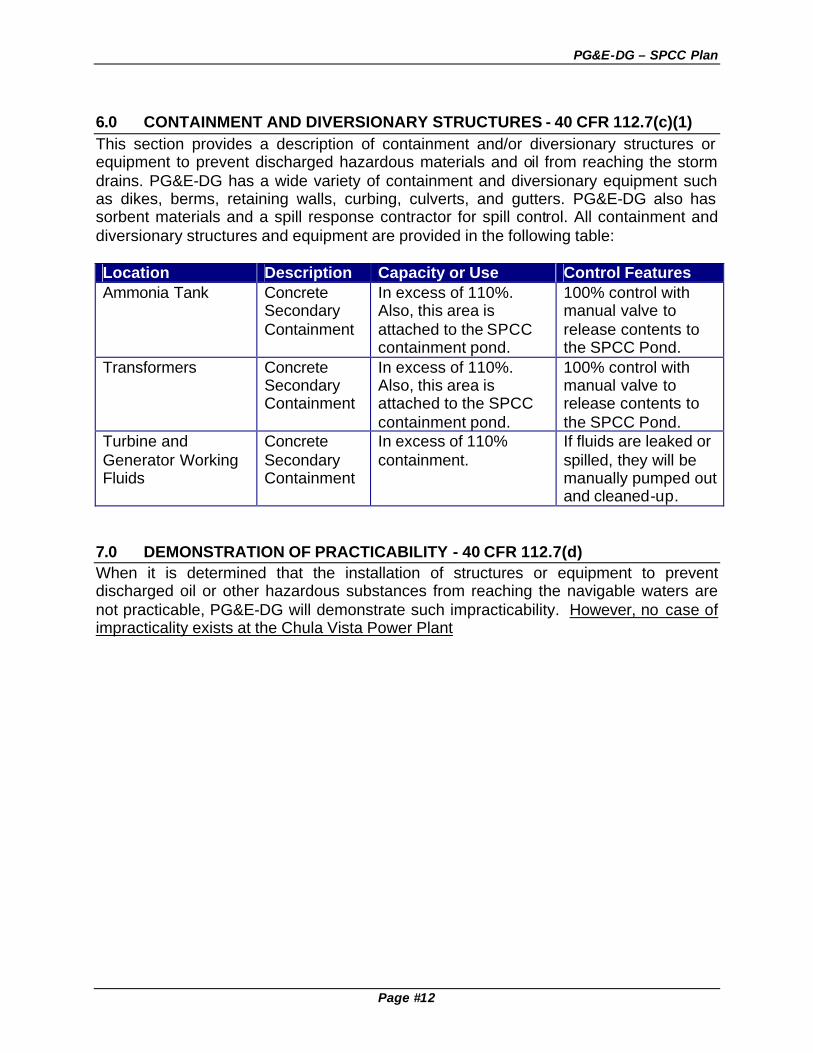
6.0 CONTAINMENT AND DIVERSIONARY STRUCTURES - 40 CFR 112.7(c)(1) This section provides a description of containment and/or diversionary structures or equipment to prevent discharged hazardous materials and oil from reaching the storm drains. PG&E-DG has a wide variety of containment and diversionary equipment such as dikes, berms, retaining walls, curbing, culverts, and gutters. PG&E-DG also has sorbent materials and a spill response contractor for spill control. All containment and diversionary structures and equipment are provided in the following table: Location Description Capacity or Use Control Features Ammonia Tank Concrete
Secondary Containment
In excess of 110%. Also, this area is attached to the SPCC containment pond.
100% control with manual valve to release contents to the SPCC Pond.
Transformers Concrete Secondary Containment
In excess of 110%. Also, this area is attached to the SPCC containment pond.
100% control with manual valve to release contents to the SPCC Pond.
Turbine and Generator Working Fluids
Concrete Secondary Containment
In excess of 110% containment.
If fluids are leaked or spilled, they will be manually pumped out and cleaned-up.
7.0 DEMONSTRATION OF PRACTICABILITY - 40 CFR 112.7(d) When it is determined that the installation of structures or equipment to prevent discharged oil or other hazardous substances from reaching the navigable waters are not practicable, PG&E-DG will demonstrate such impracticability. However, no case of impracticality exists at the Chula Vista Power Plant

PG&E-DG – SPCC Plan
Page #13
8.0 PG&E-DG FACILITY DRAINAGE - 40 CFR 112.7(e)(1) PG&E-DG has designed and installed a variety of curbs and berms to control facility drainage. The majority of the curbs and berms are designed to direct and segregate storm water on the facility. For example, storm water from vegetation areas is segregated from storm water in on roadways and in containment areas. Similarly, PG&E-DG has performed grading to minimize the potential for storm water run-off and run-on at facility boundaries. All surface drainage at the facility flows into the Otay River via the storm drain system Attachment #1 provides a facility diagram and existing storm drainage locations at the facility. SPCC Facility Drainage Practices: • All outdoors secondary containment areas empty into the containment pond, which is
later discharged to the POTW. • All storm drains at PG&E-DG will have clearly-labeled warnings (i.e., “Drains to Otay
River”) • If valves used for the drainage of containment areas are manually-operated.
Procedures are in place to ensure that they closed when not in use.

PG&E-DG – SPCC Plan
Page #14
9.0 BULK STORAGE TANKS - 40 CFR 112.7(e)(2) PG&E-DG has several types aboveground storage tanks. The main bulk storage tank is located at the facility Aqueous Ammonia system, which is used for the Selective Catalytic Reduction (SCR) System. Other bulk storage containers include transformers that contain non-PCB cooling oil. • No tanks are to be used for the storage of oil or other hazardous materials unless its
material and construction are compatible with the material stored and conditions of storage such as pressure and temperature.
• All permanent bulk storage tank installations are constructed so that a secondary means of containment is provided for the entire contents of the largest single tank plus sufficient freeboard to allow for precipitation. Rainwater that accumulates in containment areas is collected and discharged to the sewer or as hazardous waste (if determined to be hazardous). All secondary containment systems will be drained after storm events, spills or leaks, in a timely manner, to prevent the overflow of the secondary containment system.
• All hazardous materials storage areas shall be free of cracks, gaps or holes and be impervious to contain any release material for a period of at least 24 hours.
• Tank installations should, as far as practical, be fail-safe engineered or updated into a fail-safe engineered installation to avoid spills. Consideration should be given to providing one or more of the following devices: (A) High liquid level alarms with an audible or visual signal at a constantly manned operation. (B) Considering size and complexity of the facility, high liquid level pump cutoff devices designed to stop flow at a predetermined tank content level.
• All visible oil leaks from tank seams, gaskets, rivets and bolts sufficiently large to cause the accumulation of oil in diked areas shall be promptly corrected.
• All storage tanks or containers will be labeled as to the contents of the type of petroleum products and the department, which is responsible for the product. If the material is waste oil the proper hazardous waste label will be affixed to the tank or container. Empty drums, tanks, or containers will be labeled as such.
• Mobile or portable oil or hazardous material tanks will be positioned or located so as to prevent spilled materials from reaching navigable waters, as practicable. A secondary means of containment, such as dikes or catchment basins, will be furnished for the largest single compartment or tank if practical.
• The PG&E-DG Operator will conduct all batch discharges to the sewer. All batch discharges will be tested prior to the discharge to the city sewer connection to assure discharge limits are met and no unauthorized materials are released into the city sewer system. Any non-routine batch discharges will require authorization from the City of San Diego's Metropolitan Industrial Wastewater Department prior to discharge. PG&E-DG Chula Vista Operator will be responsible for filing a Batch Discharge Request to discharge into the city sewer connection. All discharge to the industrial sewer will be in compliance with the facilities Industrial User Discharge (IUD) Permit.
• All tanks, containers, and secondary containment system will be inspected by the facility operator or his designated representative for the area to ensure leaks, spills or other damage has not occurred to these containers.

PG&E-DG – SPCC Plan
Page #15
10.0 TRUCK LOADING/UNLOADING - 40 CFR 112.7(e)(4) All hazardous substance and oil transfers that involve a tank truck will follow basic procedures to minimize the potential for spills. SPCC Truck Loading and Unloading Practices: • Tank truck loading/unloading procedures will meet the minimum requirements and
regulation established by the Department of Transportation. • PG&E-DG Operators and suppliers personnel will have secondary containment. • All containers or tanks should be placed so as to avoid damage or collision with
traffic and other obstacles. • All tanks and containers should be completely inspected prior to and during delivery to
ensure that no leak exists or drain valves are open • An interlocked warning light or physical barrier system, or warning signs, should be
provided in loading/unloading areas to prevent vehicular departure before complete disconnect of flexible or fixed transfer lines.
• Prior to filling and departure of any tank truck, the lowermost drain and all outlets of such vehicles should be closely examined for leakage. If necessary, outlets will be tightened, adjusted, or replaced to prevent liquid leakage while in transit.
• PG&E-DG has detailed procedures for aqueous ammonia unloading procedures.

PG&E-DG – SPCC Plan
Page #16
11.0 INSPECTION AND RECORDS - 40 CFR 112.7(e)(8) Inspections required by this part are in accordance with written procedures developed for the facility. These written procedures and a record of the inspections, signed by the appropriate supervisor or inspector, will be made part of the SPCC Plan and maintained for a period of three years. PG&E-DG’s Chula Vista Operator is directly responsible for ensuring compliance with the PG&E-DG’s SPCC Plan. PG&E-DG Operator will coordinate inspections with all individuals that are directly affected by this plan. 12.0 SECURITY - 40 CFR 112.7(e)(9) Security measures at this facility are designed to prevent spills due to unauthorized entry and vandalism to the facility. PG&E-DG’s Security consists of round-the-clock surveillance of the facility, which greatly reduces the likelihood of leaks or spills caused by unauthorized tampering or vandalism. A fence with barbed wire to prevent people from entering surrounds the entire facility. Entrance gates are kept locked at all times. PG&E-DG’s Security performs inspections on security systems such as access control, lighting, fencing, and others, to ensure their adequacy and effectiveness. 13.0 TRAINING AND SPILL PREVENTION PROCEDURES - 40 CFR 112.7(e)(10) SPCC training is conducted for applicable plant operators and maintenance personnel regularly to insure that the facility operators are fami liar with oil spill prevention procedures. Individual training sessions emphasize any or all of the following subjects: overview of SPCC regulations, SPCC Manual review, facility inspections, oil release potential, oil spill response procedures, emergency contacts, oil spill history, storm water discharge policy, oil transfer operating procedures, or equipment modifications. The Training Coordinator keeps training records. The cause of most oil and hazardous substance spills is improper procedures rather than equipment failure. In most cases, proper inspection and maintenance can avoid equipment failures. The PG&E-DG SPCC training program is comprised of general and specific training in relation to job responsibility. A basic description of training is as follows: All new employees will receive basic safety and environmental training that outlines the safe handling of chemical and petroleum products. This training will include a minimum of the following items: • A review of PG&E-DG’s Written Hazard Communication Program. • Understanding of the pertinent pollution prevention subjects of the facility SPCC plan. • A discussion of environmental procedures and requirements as they apply to a new
employee's job. • A review of spill notification and emergency response procedures for spill that may
occurs within the yard. • An acknowledgment by the new employee that failure to comply with PG&E-DG and
federal and state regulations concerning oil spill prevention may result in adverse

PG&E-DG – SPCC Plan
Page #17
action against the employee, including disciplinary action, suspension, or termination, depending on the circumstances.
All employees that have job functions, which involve storage or handling of petroleum products or the hazardous materials/wastes, will receive, spill prevention training. This training will include the following: • A review of the pertinent sections of the SPCC plan, including procedures and
requirements related to the specific job responsibilities. • A review of potential spill areas and any past spills that have occurred in the
department and the corrective action to prevent such spills from happening again. • Inspection procedures of all storage of petroleum products and any hazardous
materials storage areas. Additional Training: Power plant and substation workers may go through an apprentice training program to learn his/her job. This on-the-job training includes procedures for spill prevention and cleanup and the handling of hazardous materials and hazardous wastes. Spill prevention and cleanup procedures are detailed in the Plant's Emergency Response Plan. All people handling PCB-contaminated materials are specially trained for their jobs. Their training includes video presentations, training sessions, and printed materials. New procedures or reminders are issued to the employees, as necessary. Each employee who handles PCB-contaminated materials receives training each year. Power Plant maintenance foremen hold weekly "Master Tailboard" meetings and the Operations foremen hold "Tailboard" meetings at the start of a shift to discuss jobs and their safety issues. Formal "Accident Prevention Meetings " are held six (6) times per year for a total of 6 hours a year per employee. PG&E-DG personnel may receive fire and fire extinguisher instruction. Electricians who work with the electrical equipment receive additional "hands-on" training. Each worker also receives a PG&E Fire Prevention Manual, which is used as a reference source, and PG&E-DG's Accident Prevention Book, which includes rules on fire protection. All physical and semi-physical PG&E employees may receive 6 hours per year of First Aid instruction. The instruction is presented by qualified personnel and includes CPR training. All personnel who are issued, or may have to wear a respirator are given training as specified in the PG&E-DG Respirator Manual.

XX
XX
XX
XX
X
X
X X
XX
XX
XX
XX
X
X
X
XX
XX
X
X
XXX
XX
XX
XX
XX
XXXXXXXXX
Transform
er Containm
ent Area
EN
TR
AN
CE
INT
ER
NA
L RO
AD
(D.G
.)
INT
ER
NA
L RO
AD
(D.G
.)
N
AC
CE
SS
RO
AD
Containm
ent Pond
Curb
Industrial Waste W
ater to Sew
erBrow
Ditch
Curb
Berm
ed Areas
10' x 10' x 2' Thick
12 T
on Rip-R
apE
nergy Dissipator
Rolled
Curb
10' x 5' x 2' Thick
12 T
on Rip-R
apE
nergy Dissipator
15' x 5' x 2' Thick
12 T
on Rip-R
apE
nergy Dissipator
Exiting 10' D
rainage Easem
ent
Spill P
revention Control and C
ountermeasure P
lan (SP
CC
) Site M
apC
:\Jaeger\Master S
ets\M
aster Set-C
hula Vista
\Chula V
ista Ram
co Binder
\Storm
Water P
lan.dwg
Am
monia T
ankC
ontainment A
rea
Trees
Planted A
reas
Denotes run-off point
3497 Main S
t, Chula V
ista, CA
SIT
E M
AP
Run-on

Attachment #2 – PG&E-DG SPCC Plan
Attachment #2
OIL SPILL CONTINGENCY PLAN 1.0 INTRODUCTION The purpose of this plan is to provide the procedures to follow when an oil or petroleum product spill occurs. This plan has been prepared according to the guidelines of the National Response Team Hazardous Materials Emergency Planning Guide and the regulations of the State of California as defined in the California Code of Regulations, Title 22, Division 4, Chapter 30, Article 20. The CCR Title 22 requirements for contingency plans embody those in 40 CFR 112, 110 and 109. 2.0 AUTHORITIES AND RESPONSIBILITIES The following discussion defines the authorities and responsibilities of PG&E-DG personnel as they pertain specifically to oil releases and associated emergencies, i.e. fires and explosions. Facility Operator (Primary Emergency Coordinator) The Facility Operator is responsible for coordinating all emergency response measures at the facility. The Facility Operator is familiar with all aspects of the facility's contingency plan, all operations and activities at the facility, the location of all records for the facility, and the facility layout. This person has the authority to commit the resources needed to carry out the contingency plan and the responsibility to respond all emergencies. Operating Foreman In addition to the Facility Operator, there are several alternate people who are responsible for coordinating emergency response measures at the facility. The Operating Foremen will coordinate with the Facility Operator or act on his/her behalf. The Operating Foremen are familiar with all aspects of the facility's contingency plan, all operations and activities at the facility, the location(s) of all applicable emergency response records for the facility, and the facility layout. These people have the authority to commit the necessary resources needed to carry out the contingency plan and the responsibility to respond to the emergency. - Assess incident: Identify hazardous materials or wastes involved. Assess effects to human health and the environment. - Activate alarm to evacuate facility personnel, if required. - Develop a plan of action to isolate incident. - Assemble emergency response team. - Follow up with reporting, recording, and monitoring review of the incident and incident response. Employee at the Scene The responsibilities of an employee at the scene of a fire, explosion, or release are: 1) To immediately report the emergency to the Facility Manager or their Supervisor. 2) To provide the following information to the Facility Operator: 1. Caller's name telephone number and identification. 2. Location and type of emergency 3. Source of spill, (if known) 4. To remain at the scene to prevent other people or vehicles from entering the emergency
area until relieved by the Facility Operator. Barricade the area, if possible.

Attachment #2 – PG&E-DG SPCC Plan
Attachment #2
5. To initiate action to stop the source of the spill, if possible. Environmental Coordinator The responsibilities of the Environmental Coordinator are to verify the spill, determine whether it is reportable, and coordinate the necessary agency notifications, and to ensure that waste and debris are disposed of according to applicable State and Federal regulations. 3.0 RESPONSE ACTIONS FOR OIL SPILLS Phase I - Notifications Upon discovery of a spill, the Facility Operator must notify the EH&S Supervisor, who will verify if the spill is reportable and will coordinate the necessary agency notifications. If this is not possible, the Facility Operator may have to contact the appropriate agencies and PG&E-DG key personnel. (See Section III-iii to III-iv) A reportable spill is defined as any quantity of oil that reaches a waterway and/or an oil quantity greater than 42 gallons on land. Phase II - Evaluation and Initiation of Action The Facility Operator must gather as much information as possible to assess the magnitude and severity of the spill in order to initiate appropriate cleanup actions. This may involve telephone calls to operations or maintenance personnel who may have seen the spill, or to office personnel who can assist in data collection. The Facility Operator must perform the following: A. Upon discovery of a spill, attempt to keep the situation from worsening by: Immediately stop the source of the discharge. He may have to: 1. shut off equipment or pumps; 2. plug a hole in operating equipment or a tank; 3. close a valve; 4. right an overturned container or piece of operating equipment. Simultaneously pursuing containment of the discharge with the following containment techniques: 1. Double check to make sure that storm drain valves are closed. 2. For relatively small spills, apply absorbent to the surface of the oil and reapply until there is
enough to absorb all the liquid. 3. For larger spills, construct earthen dikes or ditches around the spill to prevent the discharge
from flowing off-site or into waterways. 4. Prevent discharge into storm drains by sealing off with plastic and/or earthen dikes. 5. If the discharge has or is likely to reach a waterway, call for the assistance of a cleanup firm
(listed in Section III Part I), who can deploy booms, sorbent booms or underflow dams. 6. Attend to any injured. Administer first aid. Call an ambulance or paramedic. 7. Identify the PCB concentration. If this information is not readily available on the equipment
or from the office records, samples must be taken and sent immediately for laboratory analysis.
8. Assess the possible hazard to human health and take appropriate actions:

Attachment #2 – PG&E-DG SPCC Plan
Attachment #2
- Isolate spill from human and vehicular contact. (Use cones, stanchions, and tape; post signs.) Order all personnel not involved with the cleanup operation to leave the area.
- If the emergency threatens them notify all facility personnel for evacuation. - If the emergency threatens human health outside the facility boundaries and local areas
must be evacuated, the State Office of Emergency Services and the local emergency assistance organizations must be notified.
Assess the potential for fires, explosions or additional spills and take appropriate actions: i. Stop processes or operations where necessary. ii. Isolate affected containers or equipment. iii. Remove non-affected, potentially hazardous materials. Assemble the emergency response personnel and provide a briefing detailing the cleanup procedures, protective clothing to be worn and equipment to be used. If facility operations are stopped, monitor for leaks, pressure buildup, gas generation, or ruptures in valves, pipes or other equipment. Phase III - Cleanup and Disposal Cleanup efforts must be undertaken to restore the affected area to its pre-spill condition to the maximum extent possible. i. For relatively small spills, absorbent will be applied and reapplied until there is enough to
absorb all the liquid. This material will be picked up with stiff brooms and shovels and placed in approved waste containers for disposal in accordance with applicable regulations.
ii. For large spills, the Facility Operator will call for the assistance of a cleanup company which is on contract with PG&E-DG. Cleanup resources are listed in Section III Part I. These firms have the necessary equipment, such as vacuum trucks, pumps and sorbents, for cleanup of major spills.
iii. For spills in buildings or on paved areas, a second application of absorbent will be spread over the contaminated area and swept with stiff brooms to remove residues, which may remain. Absorbent will then be placed on the surface and swept up to remove any remaining moisture.
iv. For oil spills on soil, the contaminated soil will be removed until there is no visual evidence of contamination. For oil spills above 50 ppm PCB, sampling and soil removal will be performed until the contamination measures less than 5 ppm PCB. Soil which has been removed will be placed in approved waste containers for disposal in accordance with applicable regulations.
For spills in catchment basins or oil retention ponds, the oil will be removed by using absorbents or with the assistance of a cleanup company. If the spill is relatively small, rolls of will be cut into manageable lengths and floated on the surface of the water to absorb the oil. For large spills, cleanup companies may use skimming and separation devices or sorbents. The Facility Operator is responsible for determining when the cleanup is complete. Depending on the nature and magnitude of the spill, this decision may be made in consultation with state or local agencies that have jurisdiction in the affected area.

Attachment #2 – PG&E-DG SPCC Plan
Attachment #2
After completion of cleanup, contaminated disposable protective clothing will be removed by cleanup personnel immediately and placed in an approved waste container for disposal. Gloves will be removed and hands will be thoroughly cleaned with waterless hand cleaner or soap and water and wiped with rags and paper towels. Rags and other waste material will also be placed in approved waste containers for disposal in accordance with federal, state and local regulations. Disposal All oil and oily debris recovered from a spill are considered hazardous waste and must be disposed in accordance with the following state and federal regulations: 1. Oil and oily debris must be packaged for disposal in oil drums or hazardous waste
dumpsters; if materials or oil are PCB-contaminated, then containers must be a "PCB-approved" type.
2. Any container (box, barrel, tank, can) that contains PCBs at 50 ppm or above, but below 500 ppm, must have a label or tag indicating that the PCB concentration is less than 500 ppm.
3. Containers of oil-soaked materials to be disposed of must be clearly labeled as "Hazardous Waste." Containers must also be labeled with the date they were placed in storage (i.e., accumulation start date).
4. All shipments of hazardous waste must be accompanied by a Hazardous Waste Manifest. The Environmental Coordinator must inspect disposal materials to ensure that they are properly packaged, labeled, and manifested as required prior to shipment. Phase IV - Documentation Reportable oil spills will be carefully documented so that sufficient information is available to notify concerned agencies. 1. The following facts about the spill will be recorded: i. Location of the incident. ii. Time, date and duration (hours) of spill. iii. Source(s) of spill. iv. Description and quantity of product spilled. v. Cause(s) of spill, including a failure analysis of system or subsystem in which the failure
occurred. vi. Resources affected or threatened by the spill. vii. Description and status of cleanup efforts. 2. For major spills, the documentation will include photographs of the following: i. Origin of the spill. ii. Pathway of the discharge. iii. Affected areas. For spills suspected of involving PCBs in unknown quantities, samples will be taken of the spilled material. Clean glass jars with Teflon liners or other appropriate sample containers will be used for sample collection. Sample collection will be documented (time, date, location, sampler, witness) and chain-of-custody procedures will be maintained. The sealed samples

Attachment #2 – PG&E-DG SPCC Plan
Attachment #2
and chain-of-custody documents will be sent to a laboratory for analysis as soon as possible or stored in a secure area. 4.0 RESPONSE FOR FIRES Phase I - Evaluation and Initiation of Action In the event of a fire or explosion, immediately notify the local Fire Department listed in Section H of Part III. The Facility Operator must then gather as much information as possible to assess the magnitude and severity of the fire or explosion to initiate emergency action. a. Identify the source of the fire or explosion. b. Assess the possible hazard to human health and take appropriate actions:
i. Isolate the fire area. Order all personnel not involved with the emergency to leave the area.
ii. If the emergency threatens them notify all facility personnel for evacuation (see Evacuation Plan).
iii. If the emergency threatens human health outside the facility boundaries and local areas must be evacuated, the State Office of Emergency Services and the local emergency assistance organizations.
c. Assemble the emergency response personnel and provide a briefing detailing the fire fighting procedures, protective clothing to be worn and equipment to be used. d. Assess the potential for the fire spreading or explosion occurring and take appropriate actions:
i. Stop processes or operations where necessary. ii. Isolate affected containers or equipment. iii. Remove non-affected, potentially hazardous materials.
e. If facility operations are stopped, monitor for leaks, pressure buildup, gas generation, or ruptures in valves, pipes or other equipment. f. If the fire is accompanied by an oil spill or release (spraying, misting), initiate emergency response for oil spills as described in Section C.2, Part III. Phase II - Containment, Termination and Cleanup a. Containment and Termination When it is safe to do so, facility personnel will attempt to contain the fire with appropriate fire extinguishers and/or the on-site fire water system until the local fire authorities arrive on the scene. b. Cleanup If the fire is accompanied by an oil spill, contain the spill and follow cleanup procedures in sections above.
Attachment #2 – PG&E-DG SPCC Plan
Attachment #2
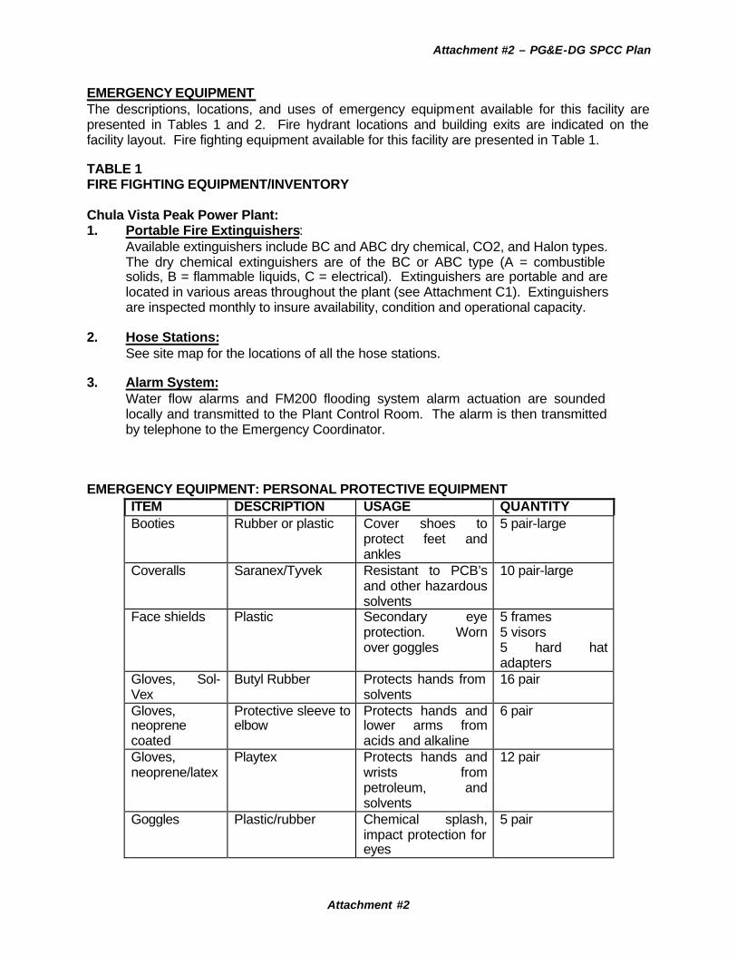
EMERGENCY EQUIPMENT The descriptions, locations, and uses of emergency equipment available for this facility are presented in Tables 1 and 2. Fire hydrant locations and building exits are indicated on the facility layout. Fire fighting equipment available for this facility are presented in Table 1. TABLE 1 FIRE FIGHTING EQUIPMENT/INVENTORY Chula Vista Peak Power Plant: 1. Portable Fire Extinguishers:
Available extinguishers include BC and ABC dry chemical, CO2, and Halon types. The dry chemical extinguishers are of the BC or ABC type (A = combustible solids, B = flammable liquids, C = electrical). Extinguishers are portable and are located in various areas throughout the plant (see Attachment C1). Extinguishers are inspected monthly to insure availability, condition and operational capacity.
2. Hose Stations: See site map for the locations of all the hose stations.
3. Alarm System: Water flow alarms and FM200 flooding system alarm actuation are sounded locally and transmitted to the Plant Control Room. The alarm is then transmitted by telephone to the Emergency Coordinator.
EMERGENCY EQUIPMENT: PERSONAL PROTECTIVE EQUIPMENT
ITEM DESCRIPTION USAGE QUANTITY Booties Rubber or plastic Cover shoes to
protect feet and ankles
5 pair-large
Coveralls Saranex/Tyvek Resistant to PCB’s and other hazardous solvents
10 pair-large
Face shields Plastic Secondary eye protection. Worn over goggles
5 frames 5 visors 5 hard hat adapters
Gloves, Sol-Vex
Butyl Rubber Protects hands from solvents
16 pair
Gloves, neoprene coated
Protective sleeve to elbow
Protects hands and lower arms from acids and alkaline
6 pair
Gloves, neoprene/latex
Playtex Protects hands and wrists from petroleum, and solvents
12 pair
Goggles Plastic/rubber Chemical splash, impact protection for eyes
5 pair

Attachment #2 – PG&E-DG SPCC Plan
Attachment #2
Hard hats Top guard slotted cap
Impact protection for head
2 each
Respirator cartridges
GMC-H Protection from organic vapors, asbestos
7 boxes of 8 each
Self Contained Breathing Apparatus
MSA-Ultralite, pressure demand
Approx. 30 minute supply of air
2 units with 2 spare bottles
COMMUNICATIONS EQUIPMENT Telephones are located in the Control Room Building. Cellular phones and pagers are available for communications with Operators at all times for operations and during emergencies. EVACUATION PLAN The Plant Manager or, in his absence, the Primary Emergency Coordinator Supervisor will make an assessment of the hazard involved, and after careful deliberation may order a partial or total evacuation of the Plant. Consideration must be given to the protection of life, property, the necessity to maintain system operations and the prevention of further hazard/damage. EMERGENCY ASSISTANCE
The following agencies will be called for assistance, if needed, during an emergency.
1) Ambulance/Paramedics 911
2) Fire Department 911
3) Hospitals 911
5) Physicians/Medical Clinics - 911 4) Police: 911 5) California Office of Emergency Services: Telephone No. (800) 852-7550

Attachment #3 – PG&E-DG SPCC Plan
Attachment #3 – PG&E-DG SPCC Plan
Certification of Applicability of an EPA Facility Response Plan (FRP)
[Sources: 40 CER 112, Also known as the "Certification of Substantial Harm Determination Form"]
Note: If there is a “yes” answer to one or more of the five questions below,
then an EPA FRP is required. Facility Name and Address: PG&E Dispersed Generation Company, LLC 3497 Main Street Chula Vista, CA 91911 1. Does the facility transfer oil over water to or from vessels and does the facility have a total oil
storage capacity greater than or equal to 42,000 gallons? Yes _____ No __X____ 2. Does the facility have a total oil storage capacity greater than or equal to 1 million gallons and
does the facility lack secondary containment that is sufficiently large to contain the capacity of the largest aboveground oil storage tank plus sufficient freeboard to allow for precipitation within any aboveground oil storage tank area? Yes ______ No __X___
3. Does the facility have a total oil storage capacity greater than or equal to 1 million gallons and
is the facility located at a distance (as calculated using the appropriate formula in 40 CFR 112 or a comparable formula) such that a discharge from the facility could cause injury to fish and wildlife and sensitive environments? Yes ______ No __X___
4. Does the facility have a total oil storage capacity greater than or equal to 1 million gallons and
is the facility located at a distance (as calculated using the appropriate formula in 40 CFR 112 or a comparable formula) such that a discharge from the facility would shut down a public drinking water intake? Yes _____ No __X___
5. Does the facility have a total oil storage capacity greater than or equal to 1 million gallons and
has the facility experienced a reportable oil spill in an amount greater than or equal to 10,000 gallons within the last 5 years? Yes ______ No __X___
“An EPA Facility Response Plan (FRP) is NOT Required” CERTIFICATION I certify under penalty of law that I personally examined and am familiar with the information submitted in this document, and that based on my inquiry of those individuals responsible for obtaining this information, I believe that the submitted information is true, accurate, and complete. Signature Date Name (type or print) Title:

Attachment #4 – PG&E-DG SPCC Plan
Attachment #4
EVACUATION PLAN
Chula Vista Peak Power Generating Plant The Chula Vista Power Generating Plant functions to provide peak power and emergency power. The plant will operate on an “as needed” basis, and will provide power during the peak demand hours of the summer months. While no emergency is anticipated, and all measures are taken to prevent such an emergency, it is possible that an evacuation of this facility may become necessary pending the occurrence of a disaster such as an earthquake, flood, fire, storm, air pollution, tsunami (tidal wave), epidemic, or riot. A plant emergency requiring total or partial evacuation may result from one or more of the following events: equipment fire (plant or switchyard), natural gas fire, hazardous material related fire, chemical release, or other condition placing plant personnel in imminent danger. In any situation requiring evacuation, the facility will take all measures necessary to preserve and secure human health, property, and the environment. A. Responsibility of the On-Scene Emergency Coordinator: 1. In the absence of The Operating Foreman, Production Supervisor, the Plant Operator being
the facility’s sole attendant, shall function as the On-Scene Emergency Coordinator. 2. Upon assessment of the hazard, the Emergency Coordinator shall order a partial or total
evacuation giving primary consideration to safety of personnel. 3. If the Operating Foreman, or Production Supervisor becomes aware of an existing or
impending hazard at the facility prior to the plant operator, they shall contact him/her by mobile radio, telephone, or pager to order evacuation.
B. Primary and Secondary Evacuation Routes: 1. Primary Route - Facility personnel shall evacuate via the office building exiting onto the
Albany access street. 2. Secondary Route - If the primary route is blocked or the emergency requiring evacuation
has occurred, exit shall be made through the west side of the facility. C. Assembly of Evacuated Personnel: 1. If multiple personnel are evacuated through the primary route, they shall assemble at the
foot of Albany Street provide the names of those unaccounted for to the Emergency Coordinator.
D. Re-entry of evacuated personnel to the plant: 1. Only those personnel designated by the Emergency Coordinator shall attempt to re-enter
the facility. 2. Upon instructions from the Emergency Coordinator, necessary personnel will re-enter the
facility in an orderly fashion following the reverse route used to evacuate earlier. 3. Should the route used to evacuate be unavailable for re-entry, an alternate route may be
prescribed by the Emergency Coordinator, and followed. 4. Upon re-entering the facility, a report of conditions as well as all present shall be given to the
Emergency Coordinator.

Attachment #5 – PG&E-DG SPCC Plan
Attachment #5
FIRST RESPONDER'S RELEASE INVESTIGATION REPORT CHULA VISTA PEAK POWER PLANTS
1. Name of first responder ______________ 2. Plant _________
3. Classification _______________________ 4. Dept. _________
5. Location of release ________________________________________
____________________________________________________________
6. Date and Time of release ___________________________________ 7. Severity of release:
( )SMALL-under 20 Gal ( )MED-under 100 Gal ( )LRG-over 100 Gal 8. Any exposures/medical treatment: ( )by Company panel doctor
( )by Hospital (First Aid) 9. Nature of release __________________________________________
____________________________________________________________
10. First responder's narrative description (How did release occur;
why; objects; equipment; tool uses; circumstances; assigned duties.) Be specific.
____________________________________________________________
____________________________________________________________
____________________________________________________________
____________________________________________________________
____________________________________________________________
11. First responder's recommendations to prevent a recurrence of this
type of release.
____________________________________________________________ ____________________________________________________________
____________________________________________________________

Attachment #5 – PG&E-DG SPCC Plan
Attachment #5
12. Supervisor's comments: Causative agent most directly related to release (object, substance, material, conditions)
____________________________________________________________
____________________________________________________________
____________________________________________________________
13. Unsafe mechanical/physical/environmental conditions at time
of release. (Be Specific)
____________________________________________________________
____________________________________________________________
____________________________________________________________
____________________________________________________________ 14. Unsafe act by operator and/or others contributing to the
release. (Be Specific.) ____________________________________________________________
____________________________________________________________
____________________________________________________________
____________________________________________________________
15. Personal factors (lack of knowledge or skill, slow reaction,
fatigue, etc.)
____________________________________________________________
____________________________________________________________
____________________________________________________________ 16. Personal protective equipment required (protective glasses,
chemical suit, hard-hat, face shield, gloves, boots, SCBA)
____________________________________________________________
____________________________________________________________ Was first responder using required equipment? ______________ If not, why? ______________________________________________
____________________________________________________________

Attachment #5 – PG&E-DG SPCC Plan
Attachment #5
17. Supervisor's recommendations: _____________________________
____________________________________________________________
____________________________________________________________
____________________________________________________________
____________________________________________________________
Supervisor's signature _______________________ Date ________ 18. Other opinions and/or recommendations:
____________________________________________________________
____________________________________________________________
____________________________________________________________
____________________________________________________________
____________________________________________________________
____________________________________________________________
____________________________________________________________
____________________________________________________________
____________________________________________________________
____________________________________________________________

Attachment #6 – PG&E-DG SPCC Plan
Attachment #6
INVESTIGATION REPORT FORM - SPILL CLEAN-UP REPORT Report Date: _____________________
1. Source of spill:
2. Date and time of spill:
3. Date and time cleanup completed:
4. Was cleanup delayed? ___________ If so, describe nature of:
Emergency/adverse weather
Length of delay
5. Describe spill location and nature of materials contaminated:
6. Circle one: Did spill occur in outdoor electrical substation, other restricted access
location, or non-restricted access area?
7. Pre-cleanup sampling data (if needed) and description of sampling methodology used
to establish spill boundaries.
8. Describe solid surfaces that were cleaned and cleaning method used:
9. Approximate depth of soil excavation:
10. Amount of soil removed:____________________________________
11. Attach post-cleanup verification sampling data. Describe post-cleanup sampling
methodology and analytical technique
EPA spill cleanup requirements have been met. The information contained in this report
is true to the best of my knowledge. Name Title Date

Attachment #7 – PG&E-DG SPCC Plan
Attachment #7
CHULA VISTA PEAK POWER PLANT EMERGENCY TELEPHONE NUMBERS
EMERGENCY COORDINATORS The following is a list of Emergency Coordinators at the Chula Vista Peak Power Generating Plant. The Operating Foreman on shift is available 24 hours a day, seven days a week and shall be notified in the event of an emergency. Additional Emergency Coordinators who are trained to respond to emergencies are also listed below. In case of no response from those named above, ask for shift operations responsible person. STOP HERE: EMERGENCY/ENVIRONMENTAL COORDINATOR WILL MAKE ANY ADDITIONAL
NOTIFICATIONS PAST THIS POINT. 1. If the hazardous substance is released or threatens to be released into the
environment in amount equal to or greater than its reportable quantity (RQ). Contact Normal Wk Hrs Off Duty Hrs National Response Center (800) 424-8802 (800) 424-8802 CA Office of Emergency Services (800) 852-7550 (800) 852-7550 AB2185 Local Implementing Agency
San Diego County Hazardous Material (619) 271-4320 911
Chula Vista Fire Department 911 911
2. If the hazardous substance is released or threatens to be released into the Otay River: Contact Normal Wk Hrs Off Duty Hrs National Response Center (800) 424-8802 (800) 424-8802 (Only if RQ is exceeded) CA Office of Emergency Services (800) 852-7550 (800) 852-7550 (Only if RQ is exceeded)
San Diego County Hazardous Material (619) 235-2111 911
Chula Vista Fire Department 911 911 S.D. Regional Water Quality (619) 286-1255
Control Board Department of Fish and Game (800) 952-5400 (800) 952-5400

Attachment #7 – PG&E-DG SPCC Plan
Attachment #7
EPA (415) 744-2000 (415) 744-2000 CA Department of Health Services, (619) 338-2222 911
Toxic Substances Control Div. U.S. Coast Guard (619) 683-6505 (24 hours) 3. If any quantity of oil is released or threatens to be released into the bay, follow the
guidelines in Item #2 above and in addition: Contact Normal Wk Hrs Off Duty Hrs California State Lands Commission Notify during
Normal wk hrs
4. Other agencies that may need to be notified depending on the incident: Contact Normal Wk Hrs Off Duty Hrs California Highway Patrol 911 911 Chula Vista Fire Department 911 911 Chula Vista Police Department 911 911 SDAPCD (858) 650-4700 Ambulance/ Paramedics 911 911 5. Notify the California Public Utilities Commission only in the event of a "serious
incident." This determination will be made jointly by the Plant Manager, Emergency and Environmental Coordinators.
Contact one of the following Normal Wk Hrs Off Duty Hrs Byron Shovlain (415) 557-1128 (415) 751-5004 Ray Duschane (415) 557-7699 (510) 471-1619 Grayson Grove (415) 557-3182 (510) 937-1137 Harry Strahl (415) 557-3107 (510) 933-1767 Russell Copeland (415) 557-3104 (510) 672-4323 Note: Notification is only required when any of the following criteria are met: 1. Personnel accidents involving PG&E-DG owned facilities resulting in death or hospitalization
of employees or the general public. 2. Power outages resulting in substantial service interruption or reduction due to facility failure,
damage or system overload. 3. A hazardous materials release that poses a threat to human health, safety, property, or the
environment. 4. Any incident having significant public impact that attracts media attention.

Attachment #8 – PG&E-DG SPCC Plan
Attachment #8
SPCC DECISION ANALYSIS
FACILITY Chula Vista Peak Power Generating Plant REGION 9, San Diego
Evaluator Thomas Coleman Date 04-20-01 Address 3497 Main Street Chula Vista, Ca 91911
STEP 1 - SPCC PLAN REQUIREMENTS Yes No 1. Does the facility have aboveground oil storage in excess of
660 gallons in a single container? (includes tanks and equipment) Χ
2. Does the facility have an aggregate aboveground oil storage volume in excess of 1,320 gallons? (includes tanks and equipment)
Χ
3. Does the facility have underground oil storage volume in excess of 42,000 gallons?
Χ
4. Does the facility store any containerized PCB-contaminated waste liquids between 50 and 500 ppm for disposal?
Χ
(If the answer to ANY of these questions is "Yes," go to Question #5. If "No," a SPCC plan is not required)
5. Could an oil spill at this facility be expected to discharge harmful quantities to "navigable" waters, including storm drains and drainage ditches, if left unattended before it could be cleaned up?
Χ
(If the answer to Question #5 is "Yes," a SPCC plan must be prepared. Go to Step 2
to determine the need for secondary containment. If the answers are ALL "No," a SPCC plan is not required)
STEP 2 - SPCC SECONDARY CONTAINMENT RECOMMENDATIONS Yes No 1. Are the "navigable" waters within 50 feet of the facility? Χ
2. Is the sensitivity of the site high? (i.e. next to a school, daycare, food processing plant, or environmentally sensitive area)
Χ
3. Are large volumes of oil transferred three or more times a week? (i.e. pumping or handling or oil products, excluding vehicle fueling)
Χ
4. Is the total facility aboveground oil volume > 100,000 gallons? Χ
5. Does the spill drainage pathway have an average slope greater than 10 percent, and does the runoff drainage area have low permeability? (i.e. average runoff coefficient > 0.6, as for compacted earth, asphalt paving, or concrete paving)
Χ
(If any one of the above questions has a "Yes" answer, secondary containment should be considered.
If two or more have "Yes" answers, secondary containment is strongly recommended. Keep in mind, however, that the SPCC regulations allow practicability to influence the final decision)

12.4 Soil Prevention/Water Quality Protection Plans This section includes supplemental information requested by the CEC. No text changes were made to Section 12.4 of the May 11, 2001 CEC Application. The attached Storm Water Pollution Prevention Plan (SWPPP) replaces the corresponding SWPPP in Addendum #1 dated May 18, 2001.

In order to add the second turbine and generator (Chula Vista II) to the Chula Vista facility, several minor modifications will be made to the Storm Water Pollution Prevention Plan (SWPPP). Most of the changes are in the form of modified facility description and site map changes. Also, some of the sample points for the monitoring plan will be changed. All of the changes will occur to the SWPPP for Chula Vista II prior to operation of the modified facility. The following provides a section by section listing of changes to be made: Section 1.0 Introduction Modification will be made to the facility description to include the Chula Vista II unit. Similarly, modifications will be made to the drainage pattern description to include the Chula Vista II units. Any changes to the industrial activities at the site as a result of the addition of Chula Vista II will be considered in the development of revisions to the SWPPP. 2.0 SWPPP Planning and Site Maps No changes will be made based on adding another turbine. 3.0 Description of Potential Pollutant Sources The description will be updated, if necessary, to include a description of Chula Vista II equipment and operations consistent with the information presented, e.g., industrial processes on-site, hazardous materials handling and storage areas, etc. Section 4.0 Non-Structural Best Management Practices (BMP’s) Procedures developed for Chula Vista I BMPs will be considered for the equipment and operations associated with Chula Vista II. The BMPs will be as consistent (as applicable) with current practices of Chula Vista I. Section 5.0 Area Structural BMP’s Procedures developed for Chula Vista I BMPs will be considered for the equipment and operations associated with Chula Vista II. The BMPs will be as consistent (as applicable) with current practices of Chula Vista I. Section 6.0 Storm Water Monitoring Plan The monitoring plan will have the same overall objectives, however additional sample points may be determined based on the new facility layout.

STORM WATER GENERAL PERMIT
STORM WATER POLLUTION PREVENTION PLAN (SWPPP)
And
STORM WATER MONITORING PLAN
For:
PG&E Dispersed Generating Company, LLC Chula Vista Peak Power Generating Plant
3497 Main Street, Chula Vista, CA
In Compliance With: The Terms and Conditions of the General Permit
To Discharge Storm Water Associated With Industrial Activity
Prepared With Assistance From: Jacobs Consulting
5161 Ellsworth Street San Diego, Ca 62110
May, 2001
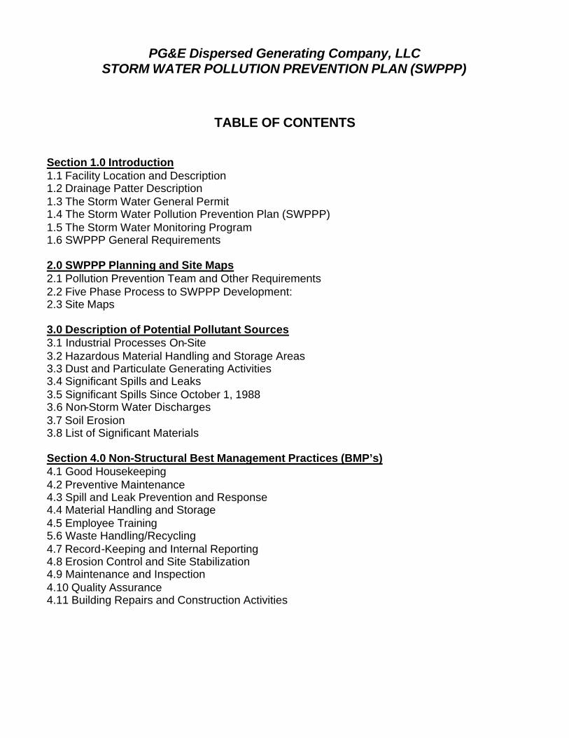
PG&E Dispersed Generating Company, LLC STORM WATER POLLUTION PREVENTION PLAN (SWPPP)
TABLE OF CONTENTS Section 1.0 Introduction 1.1 Facility Location and Description 1.2 Drainage Patter Description 1.3 The Storm Water General Permit 1.4 The Storm Water Pollution Prevention Plan (SWPPP) 1.5 The Storm Water Monitoring Program 1.6 SWPPP General Requirements 2.0 SWPPP Planning and Site Maps 2.1 Pollution Prevention Team and Other Requirements 2.2 Five Phase Process to SWPPP Development: 2.3 Site Maps 3.0 Description of Potential Pollutant Sources 3.1 Industrial Processes On-Site 3.2 Hazardous Material Handling and Storage Areas 3.3 Dust and Particulate Generating Activities 3.4 Significant Spills and Leaks 3.5 Significant Spills Since October 1, 1988 3.6 Non-Storm Water Discharges 3.7 Soil Erosion 3.8 List of Significant Materials Section 4.0 Non-Structural Best Management Practices (BMP’s) 4.1 Good Housekeeping 4.2 Preventive Maintenance 4.3 Spill and Leak Prevention and Response 4.4 Material Handling and Storage 4.5 Employee Training 5.6 Waste Handling/Recycling 4.7 Record-Keeping and Internal Reporting 4.8 Erosion Control and Site Stabilization 4.9 Maintenance and Inspection 4.10 Quality Assurance 4.11 Building Repairs and Construction Activities

PG&E – Dispersed Generating Company, LLC STORM WATER POLLUTION PREVENTION PLAN (SWPPP)
TABLE OF CONTENTS (Cont.) Section 5.0 Area Structural BMP’s 5.1 Ammonia Tank Containment Area 5.2 Loading Platform Area 5.3 Transformer Foundation Area 5.4 Ammonia Sensor Alarms Area 5.5 SPCC Containment Pond Area Section 6.0 Storm Water Monitoring Plan 6.1 Introduction and Objectives 6.2 Visual Inspection an Monitoring of Storm Water Flows 6.3 Sample Storm Water Discharge Locations 6.4 Storm Water Sampling Procedure: 6.5 Annual Inspection 6.6 Annual Comprehensive Site Compliance Evaluation 6.7 Record-Keeping 6.8 Annual Reporting Section 7.0 - ATTACHMENTS A - Notice of Intent (NOI) B - Annual Report Form C – Form 1 - Sampling and Analysis Results (First and Second Event) D – Form 2 – Quarterly Visual Observations of Authorized Non-Storm Water Discharges E – Form 3 – Quarterly Visual Observations of Unauthorized Non-Storm Water Discharges F – Form 4 - Monthly Visual Observation of Storm Water Discharges G – Form 5 – Annual Comprehensive Site Compliance Evaluation Section 8.0 – Annual Reports From Past Years

PG&E Dispersed Generating Company, LLC STORM WATER POLLUTION PREVENTION PLAN (SWPPP)
Section 1.0 Introduction
1.1 Facility Location and Description PG&E Dispersed Generating Company, LLC (PG&E-DG) operates a power generation facility that falls under Standard Industrial Classification (SIC) Codes 3511 and 3612. The industrial facilities at this site are exposed to storm water therefore, the facility must be covered under the Storm Water General Permit. PG&E-DG filed a Notice of Intent on February 19, 2001 (See Attachments). The power plant is located at 3497 Main Street in the City of Chula Vista, CA. The property consists of one legal parcel (APN 629-062-04-00) that has no frontage on Main Street. The property is approximately 835 feet south of Main Street. A 20-foot wide private easement road provides access to the site. The road is partially paved and gravel. The entire site has been graded and some areas improved with pea gravel and coarse sand. Other areas are improved with equipment areas and structures. All storm water from the site drains to the south into the Otay River and to the west into a drainage swale that empties into the Otay River. The properties to the north and east are occupied by auto storage and wrecking yards. The property to the west is currently vacant, but was previously used as a trailer storage yard. A single-family home residential area is located across the vacant lot to the west. The surrounding area south of Main Street is characterized by similar auto storage and dismantling activities. The Otay River Valley is located along the property’s southern boundary. The facility is designed to be compliant with all governing local, State and Federal Law and Regulations, including but not limited to the Chula Vista industrial zone codes, Air Pollution Control permits, Department of Environmental Health permits, and local fire department requirements. Storm water pollution prevention is addressed through compliance with the General Permit and this SWPPP. The facility consists of two natural gas fired combustion turbines and one generator. The air-cooled gas turbine is housed within an enclosure. The turbine is fitted with air pollution control equipment, noise suppression devices and exhaust stack. The Selective Catalytic Reduction (SCR) air pollution control equipment uses aqueous ammonia injection. The facility has state-of-the-art air pollution control equipment including Dry Low NOx burners. The facility is fueled solely by natural gas. Natural gas is delivered via an existing 8-inch San Diego Gas and Electric gas transmission pipeline. Electricity output is transported over an existing San Diego Gas and Electric 69 kV transmission line feeding the Otay Substation. Water use is limited to on-site domestic use. An on-site electrical substation will transform the electric output to 69,000 volts.

PG&E Dispersed Generating Company, LLC STORM WATER POLLUTION PREVENTION PLAN (SWPPP)
1.2 Drainage Patter Description The only portions of the site that are paved are the concrete pads for turbine and equipment enclosures, ammonia unloading area, and the electrical substation. The paved area includes approximately 14,000 sq. ft. (8-percent of the 3.8-acre site). The Chula Vista site maintains no storm drains on site. Storm water discharges to storm conveyance systems, which originate upland from PG&E-DG and make their way to the Otay River at this facility. The Federal Emergency Management Administration (FEMA) floodplain maps show the site as being within a 100-year floodplain. However, the maps were prepared prior to the filling of the site that occurred several years ago. The FEMA maps indicate the 100-year floodplain level at the site is 44 feet Above Mean Sea Level (AMSL). However, the site has been filled to a minimum elevation of 55 feet AMSL. Thus, the site is 10 to 11 feet above the 100-year floodplain level. 1.3 The Storm Water General Permit The General Permit is a comprehensive permit that requires facility operators to: 1. Eliminate unauthorized non-storm water discharges 2. Develop and implement a Storm Water Pollution Prevention Plan (SWPPP) 3. Perform Storm Water Monitoring of authorized non-storm water discharges 4. Prepare an Annual Report containing all records including Visual Inspection and
Storm Water Monitoring results The General Permit prohibits discharges of material other than storm water (non-storm water discharges) that are not authorized by the General Permit. This PG&E-DG facility fits into the Light Industry category and falls under the General Permit based on its SIC Codes. 1.4 The Storm Water Pollution Prevention Plan (SWPPP) The General Permit requires development and implementation of an SWPPP emphasizing storm water pollution prevention Best Management Practices (BMP’s). This approach provides the flexibility necessary to establish appropriate BMP’s for different types of industrial activities and pollutant sources. The General Permit covers many different types of facilities, the Regional Water Quality Control Board (RWQCB) and the State Water Board recognize that there is no single best way of developing or organizing an SWPPP. However, the regulation identifies general requirements that are essential elements, which all facility operators must consider and address in their SWPPP. All facility operators must prepare, retain on site, and implement an SWPPP. The SWPPP has two major objectives: (1) To help identify the sources of pollution that affect the quality of industrial storm
water discharges and authorized non-storm water discharges. This PG&E-DG

PG&E Dispersed Generating Company, LLC STORM WATER POLLUTION PREVENTION PLAN (SWPPP)
facility is new and will establish the procedures to eliminate all non-storm water discharges.
(2) To describe and assure the implementation of BMP's to reduce or prevent pollutants in industrial storm water discharges and authorized non-storm water discharges.
All conveyances will be evaluated to determine whether they convey unauthorized non-storm water discharges to the storm drain system. Unauthorized non-storm water discharges will be eliminated at this site. 1.5 The Storm Water Monitoring Program The General Permit requires development and implementation of a storm water monitoring program. The objectives of the monitoring program are to: 1. Demonstrate compliance with the General Permit 2. Aid in the implementation of the SWPPP 3. Measure the effectiveness of the BMP’s in reducing or preventing pollutants in
storm water discharges and authorized non-storm water discharges All facility operators are required to: 1. Perform visual observations of storm water discharges and authorized storm water
discharges. 2. Collect and analyze samples of storm water discharges. Analysis must include pH,
total suspended solids (TSS), total organic carbon (TOC), specific conductance, toxic chemicals, and other pollutants, which are likely to be present in storm water.
1.6 SWPPP General Requirements The SWPPP will be retained on site and made available upon request of an authorized representative of the San Diego RWQCB upon proof of proper credentials. The SWPPP will be revised, updated and implemented prior to changes in industrial activities that: 1. may significantly increase the quantities of pollutants in storm water discharge, 2. cause a new area of industrial activity at the facility to be exposed to storm water, or 3. begin an industrial activity, which would introduce a new pollutant source at the
facility.

PG&E Dispersed Generating Company, LLC STORM WATER POLLUTION PREVENTION PLAN (SWPPP)
2.0 SWPPP Planning and Site Maps 2.1 Pollution Prevention Team and Other Requirements The General Permit requires that the SWPPP identify specific individuals to a storm water pollution prevention team responsible for developing and implementing the SWPPP. The SWPPP team will implement the plan, perform inspections, and conduct all monitoring program activities as required by the General Permit. The PG&E-DG Regional Manager shall be primarily responsible for all SWPPP compliance activities. A committee will be comprised of the following personnel to assure compliance with the SWPPP : Name Title SWPPP Title Thomas Coleman
Regional Manager SWPPP Program Manager
Assistant Operations Manager
SWPPP Assistant
Safety Official SWPPP Training Coordinator
2.2 Five Phase Process to SWPPP Development and Implementation: The SWPPP has objectives that are focused on identifying and evaluating sources of pollutants associated with industrial activities that may affect the quality of storm water discharges from the PG&E-DG Chula Vista facility. One of the central themes is identifying and implementing site-specific best management practices (BMP’s) to reduce or prevent pollutants in storm water discharges. BMP’s may include a variety of pollution prevention procedures or other structural pollution control measures. They are generally categorized as Non-Structural BMP’s (activity schedules, prohibitions of practices, maintenance procedures, and other low-cost measures) and as Structural BMP’s (treatment measures, run-off controls, over-head coverage.) To achieve the objectives of the SWPPP, PG&E-DG uses a five-phase process for development and implementation displayed in the flow-chart on the following page:

PG&E Dispersed Generating Company, LLC STORM WATER POLLUTION PREVENTION PLAN (SWPPP)
FIVE PHASES FOR DEVELOPING AND IMPLEMENTING INDUSTRIAL STORM WATER POLLUTION PREVENTION PLANS
1 - PLANNING AND ORGANIZATION Form Pollution Prevention Team Review other plans (Business Plan and Risk Management Plan)
2 - ASSESSMENT PHASE Develop Site Maps Identifying Drainage Flow Patterns Identify Potential Pollutant Sources Inventory of Materials and Chemicals On Site List All Significant Spills and Leaks Identify and Eliminate All Non-Storm Water Discharges
3 - BEST MANAGEMENT PRACTICES IDENTIFICATION PHASE Implement Non-Structural BMP’s Design, Install and Utilize Structural BMP’s Select Activity, Procedural, and Other Site-Specific BMP’s
4 - IMPLEMENTATION PHASE Train Employees to Prevent Storm Water Pollution Implement BMP’s On-Site Through Training and Procedures Conduct Record-Keeping and All Required Reporting
5 - EVALUATION / MONITORING Conduct Annual Site Evaluations and Feedback Review Monitoring Information For BMP Improvement Evaluate BMP’s For Effectiveness Review and Revise the SWPPP as needed

PG&E Dispersed Generating Company, LLC STORM WATER POLLUTION PREVENTION PLAN (SWPPP)
2.3 Site Maps This SWPPP includes a site map to illustrate the facility. Site maps are essential for understanding the facility and surroundings. The site map should be clear and understandable. The following information is included on the site map: • The facility boundaries • The outline of all storm water drainage areas within the facility boundaries • Portions of the drainage area impacted by run-on from surrounding areas • Direction of flow of each drainage area • On-site surface water bodies and areas of soil erosion • Identify nearby water bodies (such as the Otay River) and municipal storm drain
inlets where the facility's storm water discharges • The location of the storm water collection and conveyance system and associated
points of discharge, and direction of flow. • Structural control measures that affect storm water discharges, run-off and run-on
(examples of structural control measures are catch basins, berms, detention ponds, secondary containment, oil/water separators, diversion barriers, etc.)
• Identify all impervious areas of the facility, including paved areas, buildings, covered storage areas, or other roofed structures.
• Locations where materials are directly exposed to precipitation • Identify areas of industrial activity (i.e., storage areas and storage tanks, shipping
and receiving areas, fueling areas, vehicle and equipment storage/maintenance areas, material handling and processing areas, waste treatment and disposal areas, dust or particulate generating areas, cleaning and rinsing areas, and other areas of industrial activity which are potential pollutant sources)
A Site Map is Provided on the Following Page:
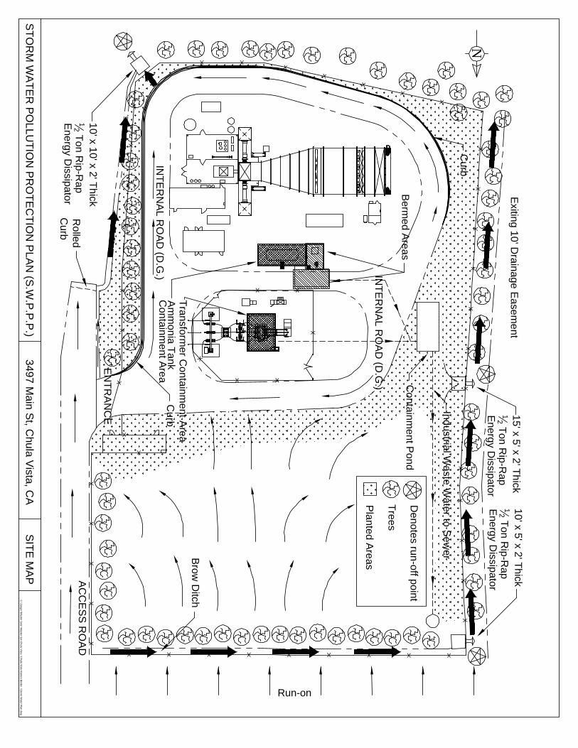
XX
XX
XX
XX
X
X
X X
XX
XX
XX
XX
X
X
X
XX
XX
X
X
XXX
XX
XX
XX
XX
XXXXXXXXX
Transform
er Containm
ent Area
EN
TR
AN
CE
INT
ER
NA
L RO
AD
(D.G
.)
INT
ER
NA
L RO
AD
(D.G
.)
N
AC
CE
SS
RO
AD
Containm
ent Pond
Curb
Industrial Waste W
ater to Sew
erBrow
Ditch
Curb
Berm
ed Areas
10' x 10' x 2' Thick
12 T
on Rip-R
apE
nergy Dissipator
Rolled
Curb
10' x 5' x 2' Thick
12 T
on Rip-R
apE
nergy Dissipator
15' x 5' x 2' Thick
12 T
on Rip-R
apE
nergy Dissipator
Exiting 10' D
rainage Easem
ent
ST
OR
M W
AT
ER
PO
LLUT
ION
PR
OT
EC
TIO
N P
LAN
(S.W
.P.P
.P.)
C:\Jaeger\M
aster Sets
\Master S
et-Chula V
ista\C
hula Vista R
amco B
inder\S
torm W
ater Plan.dw
g
Am
monia T
ankC
ontainment A
rea
Trees
Planted A
reas
Denotes run-off point
3497 Main S
t, Chula V
ista, CA
SIT
E M
AP
Run-on

PG&E Dispersed Generating Company, LLC STORM WATER POLLUTION PREVENTION PLAN (SWPPP)
3.0 Description of Potential Pollutant Sources Included in this section of the SWPPP is a narrative description of the industrial activities at the Chula Vista site. There are very few potential pollutants utilized and/or generated in the processes and activities at the site that could potentially affect the storm water quality. Most of the site consists of roadways, rooftops, and machinery space. The following items describe the facility's industrial activities and potential pollutant sources: 3.1 Industrial Processes On-Site Gas Turbine: The facility consists of one natural gas fired combustion turbine and associated generator. The air-cooled gas turbine (approximately 70 feet in length, 15 feet wide and 11 feet high) is housed within an enclosure 100 feet in width, 80 feet long and 25 feet high. The turbine is fitted with air pollution control equipment, noise suppression devices and an exhaust stack. The Selective Catalytic Reduction (SCR) air pollution control equipment uses aqueous ammonia injection and is approximately 70 feet in length, 35 feet wide and 40 feet high. The exhaust stack is approximately 15 wide, 20 long and 45 feet high. Electrical Substation: The facility taps into the existing 69,000-volt line along the eastern edge of the site. An on-site electrical substation will transform the electric output to 69,000 volts to match the existing line. The electrical substation has transformers that contain cooling oils (non-PCB). Approximately 5,200 gallons of insulation oil will be contained in the transformers. The entire foundation where the substation is mounted has a secondary containment system that would catch oil if a leak were to occur. At a minimum, the secondary containment volume is large enough to contain 110% of the total oil contained. Aqueous Ammonia System: PG&E-DG uses aqueous ammonia to control emissions of oxides of nitrogen (NOx) from the natural gas turbine exhaust at the Chula Vista power generation facility. The aqueous ammonia is stored in a single 12,000-gallon tank. The aqueous ammonia is pumped to a Selective Catalytic Reduction (SCR) process where it is released into the exhaust stream to reduce NOx emissions. Thus, aqueous ammonia usage is essential to complying with applicable air quality standards and regulations to provide adequate public health protection from NOx emissions. The aqueous ammonia system will only be pressurized when the turbine operates, which is estimated to be less than 5,000 hours per year (although the storage tank will probably always have a slight positive pressure). Ammonia at normal temperatures and pressures is a colorless gas made up of one part nitrogen and three parts hydrogen (NH3). It is lighter than air and has a sharp pungent odor that serves as a warning of its presence. Although ammonia is a relatively toxic substance, it is not a cumulative poison. It is highly soluble in water and forms a solution

PG&E Dispersed Generating Company, LLC STORM WATER POLLUTION PREVENTION PLAN (SWPPP)
known as ammonium hydroxide, which is commonly used as a household cleaner. The Department of Transportation (DOT) classifies aqueous ammonia as a nonflammable liquid. The ammonia tank is located on a large foundation that has full secondary containment with approximately 150% capacity of the 12,000 gallon storage tank. Therefore, if the tank were to fail, the entire contents could be contained and there would be no possibility for discharge into the storm drain system or directly into the Otay River. 3.2 Hazardous Material Handling and Storage Areas Aqueous Ammonia: Shipments of aqueous ammonia arrive at the facility as needed. There are very specific procedures in place to ensure that spills and accidents do not occur. Also, there is a loading pad that is designed to capture and contain the ammonia if a spill were to occur during offloading. Therefore, the potential for aqueous ammonia to discharge to the Otay River is virtually eliminated. Transformer Oils: Transformer oils are encased in the transformers when they arrive. The oils will be changed every couple of years. The area has secondary containment and discharges to the storm water system are highly unlikely. Miscellaneous Maintenance Fluids: Maintenance personnel will utilize small quantities of hazardous materials to maintain the facility and keep equipment in good operation. These materials include lubricants, solvents, and paints. These materials will be stored in a hazardous materials storage cabinet on site. The maintenance personnel will be trained in storm water pollution prevention and hazardous material management. This will ensure that hazardous materials used on-site do not discharge with storm water. 3.3 Dust and Particulate Generating Activities PG&E-DG has very few industrial activities that generate dust or particulate that may be deposited within the facility's boundaries. The majority of particulate generated on-site will be from truck traffic and miscellaneous maintenance functions (i.e. welding and painting). The emission from the turbine will be negligible with respect to storm water contamination. 3.4 Significant Spills and Leaks PG&E-DG has operated at this location in May, 2001. PG&E-DG has no knowledge or relation to any materials spilled or leaked in significant quantities into storm water discharges or non-storm water discharges since April 17, 1994. 3.5 Significant Spills Since October 1, 1988 Similarly, PG&E-DG has no knowledge of any significant materials having been spilled, leaked, or otherwise accidentally released in significant quantities to storm drains after October 1, 1988.

PG&E Dispersed Generating Company, LLC STORM WATER POLLUTION PREVENTION PLAN (SWPPP)
3.6 Non-Storm Water Discharges PG&E-DG will have zero non-storm water discharges to the storm drain system or the Otay River. The plant is a new installation and efforts are focused on having no non-storm water discharges to the Otay River. 3.7 Soil Erosion Soil erosion will be managed at this facility. The facility is designed to manage storm water flows with minimal erosion. A dissipater is installed where the storm water flows into the Otay River Valley. Similarly, berms, grading, and vegetation are used extensively to ensure that storm water flows are controlled and erosion is minimized. 3.8 List of Significant Materials PG&E-DG has very few significant materials handled and stored at the site. Essentially, the following substances are the vast majority of potential pollutants on-site: • Aqueous Ammonia (<19% by weight) • Transformer Oil (Non PCB) • Other Lubricants • Miscellaneous paints and Maintenance materials
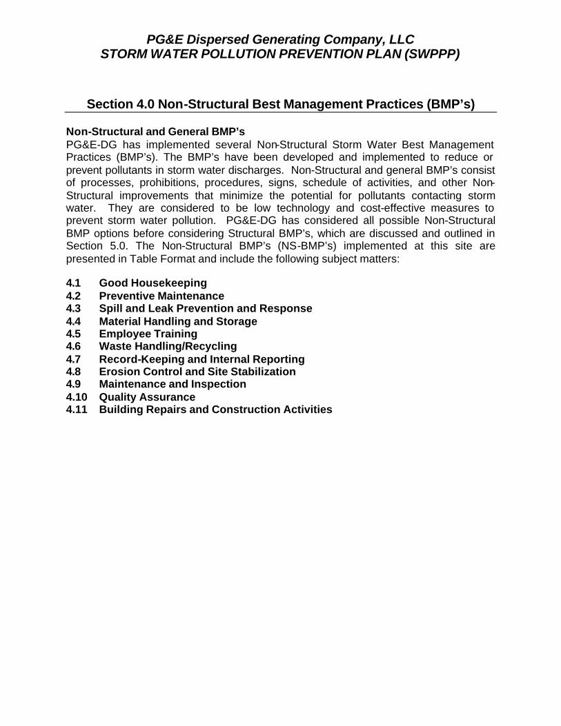
PG&E Dispersed Generating Company, LLC STORM WATER POLLUTION PREVENTION PLAN (SWPPP)
Section 4.0 Non-Structural Best Management Practices (BMP’s)
Non-Structural and General BMP’s PG&E-DG has implemented several Non-Structural Storm Water Best Management Practices (BMP’s). The BMP’s have been developed and implemented to reduce or prevent pollutants in storm water discharges. Non-Structural and general BMP’s consist of processes, prohibitions, procedures, signs, schedule of activities, and other Non-Structural improvements that minimize the potential for pollutants contacting storm water. They are considered to be low technology and cost-effective measures to prevent storm water pollution. PG&E-DG has considered all possible Non-Structural BMP options before considering Structural BMP’s, which are discussed and outlined in Section 5.0. The Non-Structural BMP’s (NS-BMP’s) implemented at this site are presented in Table Format and include the following subject matters: 4.1 Good Housekeeping 4.2 Preventive Maintenance 4.3 Spill and Leak Prevention and Response 4.4 Material Handling and Storage 4.5 Employee Training 4.6 Waste Handling/Recycling 4.7 Record-Keeping and Internal Reporting 4.8 Erosion Control and Site Stabilization 4.9 Maintenance and Inspection 4.10 Quality Assurance 4.11 Building Repairs and Construction Activities

PG&E Dispersed Generating Company, LLC STORM WATER POLLUTION PREVENTION PLAN (SWPPP)
4.1 NS-BMP #1 Non-Structural BMP Good Housekeeping
The process of practical procedures to maintain a clean and orderly site, to separate water from pollutants, and to separate pollutants from water is essential to Storm Water Pollution Prevention. The following items are performed at this site: • All Spills will be prevented from entering storm drains or
discharge points. • PG&E-DG will eliminate illegal connections to the storm
drain. There never have been and Never will be. Only Storm Water is allowed to discharge to the Storm Drain System.
• PG&E-DG will routinely inspect and clean out all storm drains, discharge point & catch basins.
• A continuous effort to control litter by sweeping and picking up litter regularly is practiced.
• Efforts are in place to keep storm drains and other discharge points (drainage channels, sheet flow areas, etc.) clear throughout the entire facility
• PG&E-DG has a policy to collect all wash water (and other non-storm water sources) and discharge to the sanitary sewer. Use "dry" cleaning methods (sweep rather than hose wash down) to clean shop floors, storage areas, access roads and equipment.
• Secondary containment measures for waste storage areas are in place.
• SDG&E will Label all storm drain inlets "No Dumping" • All spills will be cleaned up immediately to minimize
safety hazards and deter spreading.

PG&E Dispersed Generating Company, LLC STORM WATER POLLUTION PREVENTION PLAN (SWPPP)
4.2 NS-BMP #2 Non-Structural BMP Preventive Maintenance
Preventive Maintenance includes the regular inspection and maintenance, including testing, of structural controls (catch basins, secondary containment, etc.) as well as other site equipment and systems. PG&E-DG has implemented and maintains a preventive maintenance (“PM”) program that establishes specific procedures and requirements to help prevent breakdowns and failures of equipment. PG&E-DG PM program revolves around inspections, testing of plant equipment, and includes a records keeping program. This record system helps to assure scheduling of tests, inspections, test results, and corrective action. PG&E-DG PM program includes all equipment and plant areas having potential for discharge. Inspection areas in the PM program includes: storage facilities, transfer pipelines, loading and unloading areas, pipes, pumps and valves, tank corrosion (internal and external), tank supports or foundation deterioration, primary and secondary containment, housekeeping, tank drain valves and integrity of storm water collection systems. Only qualified personnel are designated to inspect equipment and plant areas. These individuals work in production and facilities related departments and have been trained to perform frequent visual inspections of their respective systems and equipment. Many routine inspections, combined with general yard clean up are conducted frequently at PG&E-DG, and thus aid in the overall effectiveness of the PM program.
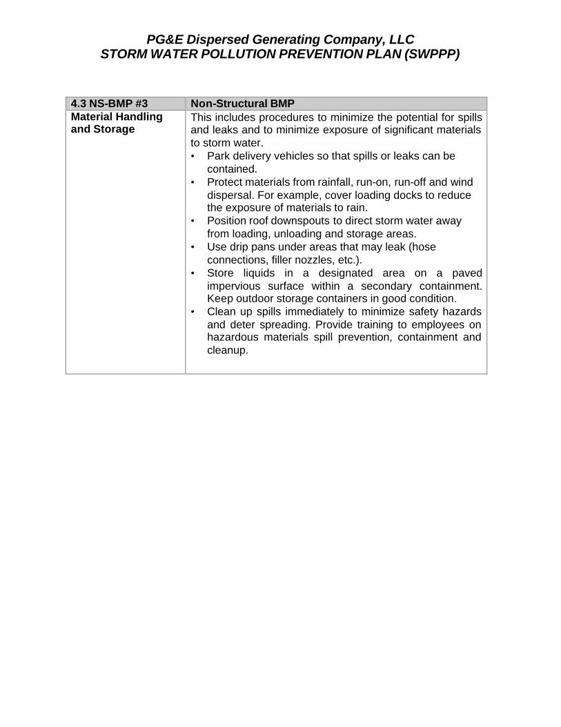
PG&E Dispersed Generating Company, LLC STORM WATER POLLUTION PREVENTION PLAN (SWPPP)
4.3 NS-BMP #3 Non-Structural BMP Material Handling and Storage
This includes procedures to minimize the potential for spills and leaks and to minimize exposure of significant materials to storm water. • Park delivery vehicles so that spills or leaks can be
contained. • Protect materials from rainfall, run-on, run-off and wind
dispersal. For example, cover loading docks to reduce the exposure of materials to rain.
• Position roof downspouts to direct storm water away from loading, unloading and storage areas.
• Use drip pans under areas that may leak (hose connections, filler nozzles, etc.).
• Store liquids in a designated area on a paved impervious surface within a secondary containment. Keep outdoor storage containers in good condition.
• Clean up spills immediately to minimize safety hazards and deter spreading. Provide training to employees on hazardous materials spill prevention, containment and cleanup.
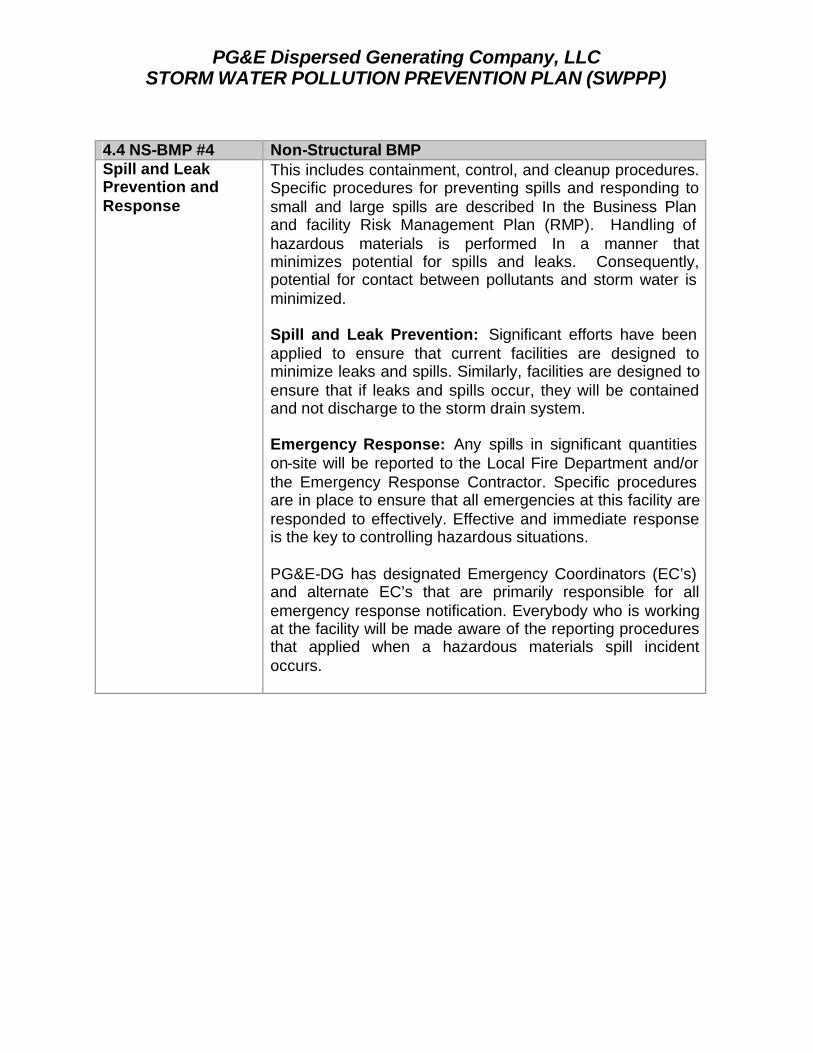
PG&E Dispersed Generating Company, LLC STORM WATER POLLUTION PREVENTION PLAN (SWPPP)
4.4 NS-BMP #4 Non-Structural BMP Spill and Leak Prevention and Response
This includes containment, control, and cleanup procedures. Specific procedures for preventing spills and responding to small and large spills are described In the Business Plan and facility Risk Management Plan (RMP). Handling of hazardous materials is performed In a manner that minimizes potential for spills and leaks. Consequently, potential for contact between pollutants and storm water is minimized. Spill and Leak Prevention: Significant efforts have been applied to ensure that current facilities are designed to minimize leaks and spills. Similarly, facilities are designed to ensure that if leaks and spills occur, they will be contained and not discharge to the storm drain system. Emergency Response: Any spills in significant quantities on-site will be reported to the Local Fire Department and/or the Emergency Response Contractor. Specific procedures are in place to ensure that all emergencies at this facility are responded to effectively. Effective and immediate response is the key to controlling hazardous situations. PG&E-DG has designated Emergency Coordinators (EC’s) and alternate EC’s that are primarily responsible for all emergency response notification. Everybody who is working at the facility will be made aware of the reporting procedures that applied when a hazardous materials spill incident occurs.

PG&E Dispersed Generating Company, LLC STORM WATER POLLUTION PREVENTION PLAN (SWPPP)
4.5 NS-BMP #5 Non-Structural BMP On-Site Personnel Training
This includes training of all on-site personnel whose actions or lack thereof could result in the discharge of pollutants. Such personnel include employees of PG&E-DG as well as other on-site personnel, subcontractors, contractors, suppliers, and others. This also includes training of personnel who are responsible for: 1) Implementing the BMP Program, 2) Conducting inspections, sampling, and visual
observations, and 3) Managing the site drainage system. Training should
address topics such as good housekeeping, material handling and storage, spill response, and actions necessary to implement all BMP’s identified in this SWPPP.
4) Records will be maintained of all training sessions. All employees have access to the Facility Safety Manual and SWPP Plan (as well as other operating procedure documents such as the Health and Safety Plan and Business Plan). Initial employee training at the facility includes a course that provides training in the new employees' specific operating area. The employee is trained In proper operating and maintenance procedures. All new employees at PG&E-DG are initially indoctrinated into the risks of working with pollutants and hazardous materials and how they relate to the SWPPP. All employees are made aware of PG&E-DG SWPPP objectives, safety hazards, practices for preventing discharges, and procedures for responding properly and rapidly to hazardous incidents. Additional specialized training is conducted for personnel directly involved with Spill Prevention and Response.

PG&E Dispersed Generating Company, LLC STORM WATER POLLUTION PREVENTION PLAN (SWPPP)
4.6 NS-BMP #6 Non-Structural BMP Waste Handling / Recycling
This includes procedures and processes to handle, store, recycle, and dispose of waste materials. Proper disposal of wastes, and recycle when possible will eliminate illegal discharges. Reduce, reuse and recycle hazardous and non-hazardous wastes when possible. • PG&E-DG will cover and berm waste storage areas
when applicable. • Keep outside areas (dumpsters, parking lots, etc.) free of
trash and debris. • Always store wastes indoors when possible. • Keep waste containers covered. • PG&E-DG has a policy to use non-toxic substitutes for
chemicals when possible. • PG&E will recycle cleaning solutions, oil, antifreeze,
batteries and fluids as much as possible in a continuous effort to improve.
• The following are some resources used for Disposal and Recycling of wastes:
RECYCLING:
NON-HAZARDOUS WASTE RECYCLING: County Recycling Hotline: (619) 467-0903 or (800) 237-2583
HAZARDOUS WASTE RECYCLING: Call the State Department of Toxic Substances Control to get a
copy of the "Directory of Industrial Recyclers and Listing of Hazardous Wastes
Available for Recycling": (916) 323-6042 DISPOSAL:
NON-HAZARDOUS WASTE DISPOSAL: County Landfills (Allied Systems, Inc.): (619) 278-6061
City Landfill (Miramar) Information: (619) 573-1418 or (619) 573-1420
HAZARDOUS WASTE DISPOSAL: County Hazardous Materials Duty Specialist: (619) 338-2231
EXCHANGE PROGRAMS: Call the California Integrated Waste Management Board to get a copy of the "California Materials Exchange (CALMAX) Catalog" :
(916) 255-2369

PG&E Dispersed Generating Company, LLC STORM WATER POLLUTION PREVENTION PLAN (SWPPP)
4.7 NS-BMP #7 Non-Structural BMP Record-Keeping and Internal Reporting
This includes procedures to ensure that all records of inspections, spills, maintenance activities, corrective actions, visual observations, etc., are developed, retained, and provided, as necessary, to the appropriate personnel. The Site Operator maintains records and plans. Other records maintained in this area include: • Hazardous Materials Business Plan • The facility’s Safety Procedures Manual • Risk Management Plan (RMP) Technical Document • Material Safety Data Sheets (MSDS) • Inspection Records • All PG&E-DG Training Records

PG&E Dispersed Generating Company, LLC STORM WATER POLLUTION PREVENTION PLAN (SWPPP)
4.8 NS-BMP #8 Non-Structural BMP Erosion Control and Ground Maintenance
Areas where building or grounds maintenance is conducted can contribute contaminants to runoff when measure have not been taken to prevent discharges. The overuse of pesticides and fertilizers, over-watering and inadequate erosion control may result in an illegal discharge. This includes all sediment and erosion control activities. This may include the planting and maintenance of vegetation, diversion of run-on and runoff, placement of sandbags, silt screens, or other sediment and erosion control devices, etc.
The existing on-site drainage pattern is to the southern property line and the Otay River and to the west where runoff flows from the property into the Otay River. The existing drainage swale is part of the City of Chula Vista storm drain system that conveys runoff from north of Main Street to the Otay River.
The grading directs surface runoff to a catch basin with a built-in filtration system in the southwest corner of the site. An 18-inch RCP storm drain conveys surface runoff to a headwall and energy dissipater located in an existing drainage swale immediately southwest of the project site.
• Utilize native vegetation to reduce water, fertilizer or pesticide needs.
• Use landscaping pesticides and fertilizers only as needed.
• Avoid over-watering to prevent excess runoff. • Use integrated pest management (IPM) where
appropriate. • Sweep paved surfaces, rather than hosing down or using
blowers. • Properly contain and dispose of wash water, sweepings
and sediments. • Educate employees on pollution prevention measures.
Landscape maintenance is performed regularly. Landscaped areas are watered when necessary, using minimum amounts o f water to maintain vegetation. Use of fertilizers and pesticides is generally not necessary. If these chemicals are used, manufacturers' Instructions are followed, and the minimum quantity needed to do the job is used. All chemicals used for vegetation are applied by a landscape maintenance contractor and are not stored on-site.

PG&E Dispersed Generating Company, LLC STORM WATER POLLUTION PREVENTION PLAN (SWPPP)
4.9 NS-BMP #9 Non-Structural BMP Maintenance and Inspections
The storm drain system is regularly inspected and maintained. All conveyance systems are inspected monthly during the dry season, and weekly and after storms during the rainy season. Any obstructions of debris observed during inspection are removed promptly. Spilled or leaked materials that could be transported by storm water are also removed, and the source of the spill or leak is eliminated. Accumulated sediments, leaves, and other debris are removed from the catch basins monthly (and before ft rains). This BMP includes an inspection schedule of all potential pollutant sources. Tracking and follow-up procedures will be implemented to ensure adequate corrective actions are taken and adequate BMP’s are developed and implemented.

PG&E Dispersed Generating Company, LLC STORM WATER POLLUTION PREVENTION PLAN (SWPPP)
4.10 NS-BMP #10 Non-Structural BMP Quality Assurance This includes procedures to ensure that the SWPPP is
adequate and that all elements of the SWPPP and Monitoring and Reporting Program are completely implemented. PG&E-DG will implement a procedure to ensure that all monitoring (visual and testing) will be conducted in compliance with the SWPPP and with the regulations. This will be accomplished through a series of management checks and reviews. The Annual Report will have an internal due date that is sufficient to ensure that it is reviewed prior to submittal.

PG&E Dispersed Generating Company, LLC STORM WATER POLLUTION PREVENTION PLAN (SWPPP)
4.11 NS-BMP #11 Non-Structural BMP Building Repairs and Construction Activities
Areas where building repair, remodeling and minor construction are conducted can contribute contaminants to runoff when measure have not been taken to prevent discharges. PG&E-DG will perform the following during construction and repair activities: • Use soil erosion control techniques if bare ground is
temporarily or permanently exposed. • Enclose painting operations, consistent with local air
quality operations and minimize or eliminate overspray on the ground or other surfaces where rainfall will contact.
• Properly store and dispose of waste materials generated from the activity.
• Properly store materials that are normally used in repair and remodeling such as paints and solvents.
• Sweep paved surfaces, rather than hosing down or using blowers.
• Properly contain and dispose of wash water, sweepings and sediments.
• Clean up spills immediately to minimize safety hazards and deter spreading.
• Control litter by sweeping and picking up trash on a regular basis.
• Maintain good housekeeping practices while work is underway.
• Train all employees about Best Management Practices to Prevent Storm Water Pollution.

PG&E Dispersed Generating Company, LLC STORM WATER POLLUTION PREVENTION PLAN (SWPPP)
Section 5.0 Area Structural BMP’s Structural BMP’s are the most effective type of pollution prevention measures that have been considered and implemented at this site. Structural BMP’s generally consist of structural devices that reduce or prevent pollutants in storm water discharges. Below is an example list of structural BMP’s that were considered at this facility: Area Structural BMP’s Overhead Coverage
This includes structures that provide coverage over or enclosure of materials, work areas, and potential pollutant sources.
Retention Ponds
This includes basins, ponds, surface impoundment’s, bermed areas, etc., which prevent pollutants from being discharged from the site.
Control Devices
This includes berms or other devices that channel or route water away from potential pollutant sources.
Secondary Containment Structures
This includes structures around storage tanks and other areas for the purpose of containing leaks and spills.
Treatment This includes inlet controls, infiltration devices, oil/water separators, detention ponds, vegetative swales, etc., which remove pollutants from water before it discharged.
At the Chula Vista facility, the Structural BMP’s are divided into areas where they are applied. The areas may have one or more struc tural BMP’s in place. Also, most of the areas have non-structural BMP’s to enhance the Area Structural BMP’s. Each Area Structural BMP is divided into a separate description for simplicity. There is some overlap between Areas, Non-Structural BMP’s and Structural BMP’s, which tends to create support and continuity. Also, the tabular form of the BMP’s provides an excellent training format for facility personnel. The Area Structural BMP’s include the following: 5.1 Ammonia Tank Containment Area 5.2 Loading Platform Area 5.3 Transformer Foundation Area 5.4 Ammonia Sensor Alarms Area 5.5 SPCC Containment Pond Area

PG&E Dispersed Generating Company, LLC STORM WATER POLLUTION PREVENTION PLAN (SWPPP)
5.1 Structural BMP #1 - Ammonia Tank Containment The aqueous ammonia is stored in a single 12,000-gallon tank. The aqueous ammonia is pumped to a Selective Catalytic Reduction (SCR) process where it is released into the exhaust stream to reduce NOx emissions. The ammonia tank is located on a large foundation that has full secondary containment with approximately 150% capacity of the 12,000 gallon storage tank. Therefore, if the tank were to fail, the entire contents could be contained and there would be no possibility for discharge into the storm drain system or into the Otay River. Area Activities Potential
Sources Pollutant Best Management Practices
1) Ammonia Tank Containment
Ammonia Storage
Spills and leaks Leaking or damaged tanks Storm water flows Berm failure Reactions with incompatible materials
Ammonia • The tank is surrounded by a berm that provides sufficient volume to contain possible spills.
• There are no material compatibility issues with the tank, its contents or the containment system.
• The secondary containment area is free of cracks and gaps, and the surface is sufficiently impervious to contain leaks and spills until they can be cleaned up.
• The surface area inside containment areas is sloped towards a low point that is used to collect spills and rainwater.
• Rainwater is collected and a manual valve allows the rainwater to be released to the containment pond.
• The area is fitted with ammonia sensors and alarms that immediately notify PG&E-DG of a spill or release.

PG&E Dispersed Generating Company, LLC STORM WATER POLLUTION PREVENTION PLAN (SWPPP)
5.2 Structural BMP #2 - Unloading Platform Area
The unloading platform area is a concrete pad that is approximately 35 feet long and 25 feet wide. The pad provides a safe area for shipments of aqueous ammonia. Tank trucks with approximately 6,000 gallons of aqueous ammonia park on the pad to perform the unloading operation. Two trained individuals perform the unloading process following specific procedures, which minimizes the likelihood for accidents and spills. The unloading pad itself is designed to control spills if such an event were to occur. The unloading pad is slopped to a sump, which provides containment in the event of a spill. Storm water from the unloading platform will be pumped to the ammonia tank secondary containment area and later discharged to the industrial sewer. This eliminates the possibility of storm water discharges from the ammonia unloading area.
Area Activities Potential
Sources Pollutant Best Management Practices
2) Loading Platform Area
Loading and Unloading of Aqueous Ammonia
Spills and Leaks Line Break Pump failure Human Error Storm water flows Reactions with incompatible materials
Aqueous Ammonia Truck Leaks
• The area is constructed of a large concrete pad that is sloped to a collection sump. The slope and sump are available to ensure directional control of aqueous ammonia in the event of a spill or line break.
• The storage and transfer of aqueous ammonia is performed in compliance with local State and Federal environmental, safety and fire codes. Workers are trained and a procedure is in place.
• The area is free of cracks and gaps, and the surface is sufficiently impervious to contain leaks and spills until they can be cleaned up. • There are no incompatible material issues with aqueous ammonia.

PG&E Dispersed Generating Company, LLC STORM WATER POLLUTION PREVENTION PLAN (SWPPP)
5.3 Structural BMP #3 - Transformer Foundation Area
This area has an electrical substation on site. The substation transforms the electricity generated into the electric output to 69,000 volts. The facility taps into the existing 69,000-volt line along the eastern edge of the site. The transformers are located on a 23’ X 21’ foundation. The electrical substation has transformers that contain cooling oils (non-PCB). Approximately 5,200 gallons of insulation oil is contained in the transformers. The entire foundation where the substation is mounted has an integrated secondary containment system that would retain oil if a leak were to occur. At a minimum, the secondary containment volume is large enough to contain 110% of the total oil contained. Transformer oils are encased in the transformers when they arrive. The oils will be changed every couple of years. Accumulated storm water in the secondary containment area is directed to a sump and is discharged to the industrial sewer. The area has secondary containment and discharges to the storm water system are highly unlikely. Area Activities Pollutant
Sources Pollutant Best Management Practices
3) Transformer Foundation Area
None Spills and Leaks Leaking or damaged tanks Storm water flows Berm failure
Insulation Oil (Non-PCB)
• The area is surrounded by a curb that provides sufficient volume to contain all possible spills.
• The storage of toxic, corrosive, reactive or ignitable materials and wastes at PG&E-DG complies with all local and state fire codes.
• The area is free of cracks and gaps, and the surface is sufficiently impervious to contain leaks and spills until they can be cleaned up.
• The surface area inside containment areas is sloped towards a low point which is be used to collect accumulated rainwater.

PG&E Dispersed Generating Company, LLC STORM WATER POLLUTION PREVENTION PLAN (SWPPP)
5.4 Structural BMP #4 - Ammonia Sensor Alarms Area
The installation of Ammonia sensors is a California Accident Release Program (CalARP) requirement. This requirement will aid in the prevention and minimization of pollution if the ammonia system integrity is compromised. There are six ammonia sensors placed around the ammonia tank and the injection grid. When triggered, these sensors will set off a series of alarms and procedures to shut the system down and stop the release. The ammonia system lines that are not in a secondary containment area are positioned over gravel and are over 75 feet from the nearest storm water discharge point. The combination of a quick system shutdown and the distance to the nearest storm water discharge point minimize the possibility for an ammonia discharge to the Otay River.
Area Activities Potential
Sources Pollutant Best Management Practices
4) Ammonia Sensor Alarms
Closed Loop System
Spills and Leaks Leaking or damaged tanks
Ammonia • The use of Aqueous Ammonia is in compliance with the California Accident Release Program (CalARP) as well as with all local and federal codes. Information on accident prevention and response are contained within the facility Risk Management Plan (RMP) and the facility Hazardous Materials Business Plan.
• Personnel are trained on the Business Plan and the RMP as well as this SWPPP.
• Alarms are triggered to ensure that the ammonia system is shut down as soon as a release occurs (see RMP for details). A quick shutdown will ensure that aqueous ammonia does not discharge to the Otay River.
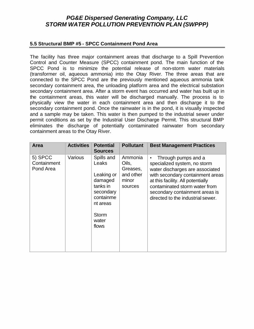
PG&E Dispersed Generating Company, LLC STORM WATER POLLUTION PREVENTION PLAN (SWPPP)
5.5 Structural BMP #5 - SPCC Containment Pond Area The facility has three major containment areas that discharge to a Spill Prevention Control and Counter Measure (SPCC) containment pond. The main function of the SPCC Pond is to minimize the potential release of non-storm water materials (transformer oil, aqueous ammonia) into the Otay River. The three areas that are connected to the SPCC Pond are the previously mentioned aqueous ammonia tank secondary containment area, the unloading platform area and the electrical substation secondary containment area. After a storm event has occurred and water has built up in the containment areas, this water will be discharged manually. The process is to physically view the water in each containment area and then discharge it to the secondary containment pond. Once the rainwater is in the pond, it is visually inspected and a sample may be taken. This water is then pumped to the industrial sewer under permit conditions as set by the Industrial User Discharge Permit. This structural BMP eliminates the discharge of potentially contaminated rainwater from secondary containment areas to the Otay River.
Area Activities Potential Sources
Pollutant Best Management Practices
5) SPCC Containment Pond Area
Various Spills and Leaks Leaking or damaged tanks in secondary containment areas Storm water flows
Ammonia Oils, Greases, and other minor sources
• Through pumps and a specialized system, no storm water discharges are associated with secondary containment areas at this facility. All potentially contaminated storm water from secondary containment areas is directed to the industrial sewer.

PG&E Dispersed Generating Company, LLC STORM WATER POLLUTION PREVENTION PLAN (SWPPP)
Section 6.0 – Storm Water Monitoring Plan 6.1 Introduction and Objectives This Storm Water Monitoring Plan has been prepared in accordance with Section B of the Storm Water General Permit. The focus of this plan is to assure that runoff discharges are in compliance with discharge standards and that management practices in place that effectively control pollutants from entering the storm drainage system. The objectives of the Storm Water Monitoring Program are to: • Assure that storm water discharges are in compliance with the Discharge
Prohibitions, Effluent Limitations, and Receiving Water Limitations specified in this General Permit
• Assure practices at the facility to reduce or prevent pollutants in storm water discharges
• Aid in the implementation and revision of the SWPPP • Measure the effectiveness of best management practices (BMP's) to prevent and
reduce pollutants in storm water discharges. 6.2 Visual Inspection an Monitoring of Storm Water Flows PG&E-DG will collect storm water samples during the first hour of discharge from the first storm event of the wet season, (i.e. first storm after October 1st 2001) and at least one other storm event in the wet season. All storm water discharge locations will be sampled. Sampling of stored or contained storm water will occur at the time the stored or contained storm water is released. If PG&E-DG does not collect samples from the first storm event of the wet season, two other storm events during the wet season will be collected. Also, an explanation why the first storm event was not sampled, will be provided in the Annual Report. The samples shall be analyzed for: 1. Total suspended solids (TSS) pH, specific conductance, and total organic carbon
(TOC). Oil and grease (O&G) may be substituted for TOC; and 2. Toxic chemicals and other pollutants that are likely to be present in storm water
discharges in significant quantities. 3. There are no additional chemicals to be analyzed based on the Standard Industrial
Classification (SIC) Code. 6.3 Sample Storm Water Discharge Locations PG&E-DG visually observes and collect samples of storm water discharges from all drainage areas. When the facility's storm water discharges are commingled with run-on from surrounding areas, the operator will identify visual observation and sample collection locations that have not been commingled by run-on. The non-mingled storm water represents the quality and quantity of the facility's storm water discharges.

PG&E Dispersed Generating Company, LLC STORM WATER POLLUTION PREVENTION PLAN (SWPPP)
All storm drains and outfalls from the property will be sampled. The storm drain and out-fall areas are identified on the Site Map. 6.4 Storm Water Sampling Procedure: Sampling will consist of a grab sample from a storm event that produces significant storm water discharge that is preceded by at least three (3) working days of dry weather. The grab sample should be taken during the first 60 minutes of the discharge. If a sample can not be taken during the first sixty (60) minutes, reasons for not collecting a grab sample will be documented in the records. The exact time will be documented. NOTE: All sampling and sample preservation shall be in accordance with the current edition of "Standard Methods for the Examination of Water and Wastewater" (American Public Health Association). All laboratory analyses must be conducted according to test procedures under 40 CFR Part 136, unless other test procedures have been specified in this General Permit or by the Regional Water Board. All metals shall be reported as total metals. All laboratory analyses shall be conducted at a laboratory certified for such analyses by the State Department of Health Services. Wet Season Visual Observations - PG&E-DG will visually observe storm water discharges from one storm event per month during the wet season (October 1st through May 30th). During this Wet Season, all storm drains and outfalls will be visually inspected during the first hour of one storm event per month that produces significant storm water discharge. Visual observations are only required of storm water discharges that occur during daylight hours that are preceded by at least three (3) working days without storm water discharges and that occur during scheduled facility operating hours. This inspection will be conducted to observe the presence of floating and suspended material, oil and grease, discoloration, turbidity, and odor, etc. Records shall be maintained of observation dates, locations observed, and response taken to reduce or prevent pollutants in storm water discharges. (See Observation Forms Section 7.0) Dry Season Observations - No less than twice during the dry season (June 1st through September 30th), all storm drains will be visually inspected for the presence of non-storm water discharges. All non-storm water discharges will be sampled and analyzed. Results shall be recorded and maintained. This facility does not have non-storm water discharges. If PG&E-DG identifies any non-storm water discharges, they will be investigated and eliminated. (See Observation Forms Section 7.0) Sampling and Observation Exceptions - PG&E-DG shall be prepared to collect samples and conduct visual observations at the beginning of the wet season (i.e. October 1st 2001) and throughout the wet season until the minimum requirements are completed with the following exceptions: 1. PG&E-DG is not required to collect a sample and conduct visual observations due to
dangerous weather conditions, such as flooding, electrical storm, etc. Similarly, samples are not required when storm water discharges begin after scheduled facility

PG&E Dispersed Generating Company, LLC STORM WATER POLLUTION PREVENTION PLAN (SWPPP)
operating hours or when storm water discharges are not preceded by three working days without discharge.
2. PG&E-DG may conduct visual observations and sample collection more than one hour after discharge begins if the PG&E-DG determines that the objectives will be satisfied. PG&E-DG shall include an explanation in the Annual Report why the visual observations and sample collection was conducted after the first hour of discharge.
6.5 Annual Inspection At a minimum, an annual inspection of the facility will be performed. This inspection will identify any areas of noncompliance. The inspection shall include the types and volumes of industrial activity in comparison with the pollution prevention measures. A certification of compliance, based upon the site inspection requirement of the General Permit and the SWPPP shall be submitted with the annual report. (First report due July 1st and annually thereafter.) 6.6 Annual Comprehensive Site Compliance Evaluation The Operator shall conduct one Annual Comprehensive Site Compliance Evaluation in each reporting period (July 1-June 30). The SWPPP shall be revised, as appropriate, and the revisions implemented within 90 days of the evaluation. Evaluations shall include the following: § A review of all visual observation records, inspection records, and sampling and
analysis results. § A visual inspection of all potential pollutant sources for evidence of, or the potential
for, pollutants entering the drainage system. § A review and evaluation of all BMP’s (both structural and non-structural) to
determine whether the BMP’s are adequate properly implemented and maintained. This will also help determine if additional BMP’s are needed. A visual inspection of equipment needed to implement the SWPPP, such as spill response equipment, will be included.
§ The evaluation report that includes, (i) Identification of personnel performing the evaluation, (ii) The date(s) of the evaluation, (iii) Necessary SWPPP revisions, (iv) Schedule for implementing SWPPP revisions, (v) All incidents of non-compliance and the corrective actions taken, and (vi) Include a certification that the facility operator is in compliance with this
General Permit (See Section 7.0 Evaluation Form).

PG&E Dispersed Generating Company, LLC STORM WATER POLLUTION PREVENTION PLAN (SWPPP)
6.7 Record-Keeping Records of all Storm Water Monitoring information and copies of all reports (including the Annual Reports) required by the General Permit will be retained for a period of five years. These records shall include: (a) The date, places, and time of she Inspections, sampling, and visual
observations; (b) The individual(s) performing these functions; (c) The date and time of analysis; (d) The laboratory and individual who performed the analysis; (e) Wet and dry season visual observation records; and (f) Visual and sample collection exception records. (g) The records of any corrective actions and follow-up activities that resulted from
the visual observations. 6.8 Annual Reporting PG&E-DG shall submit an Annual Report by July 1st of each year to the Executive Officer of the San Diego Regional Water Quality Control Board (RWQCB). The report shall include a summary of visual observations, and sampling results. The report shall also have a narrative evaluation of the visual observation and sampling and analysis results with laboratory reports. The report shall have the write -up of the Annual Comprehensive Site Compliance Evaluation. The annual report shall have all records associated with storm water attached. PG&E-DG shall prepare and submit their Annual Reports using the annual report forms provided by the San Diego RWQCB. The Annual Report shall be signed and certified in accordance with Standard Provisions General Permit as presented below: “I certify under penalty of law that this document and all attachments were prepared under my direction or supervision in accordance with a system designed to ensure that qualified personnel properly gather, and evaluate the information submitted. Based on my inquiry of the person or persons who manage the system, or those persons directly responsible for gathering the information, the information submitted, is, to the best of my knowledge and belief, true, accurate, and complete. I am aware that there are significant penalties for submitting false information, including the possibility of fine and imprisonment for knowing violations."