Embed Size (px)
Citation preview
Ash Pond 1, Clinch River Plant
Attachment D
Construction Quality Assurance Plan
Quality Assurance/Quality Control Plan
Pond 1 Ash Disposal Area Closure
Clinch River Plant
Appalachian Power Company
Clinch River Plant, Carbo, Virginia
April 2016
Prepared by: American Electric Power Service Corporation
and Appalachian Power Company
1 Riverside Plaza
Columbus, OH 43215
and
Amec Foster Wheeler
Environment & Infrastructure Inc.
9725 Cogdill Road
Knoxville, TN 37932
Pond 1A/1B - Clinch River Plant
Pond 1A/1B Pond Closure QA/ QC Plan Page i April 2016
TABLE OF CONTENTS
1.0 PERSONNEL AND QUALIFICATIONS ......................................................................................................... 3
1.01 Construction Quality Assurance Certifying Engineer .......................................................................... 3
1.02 Quality Assurance Officer .................................................................................................................... 3
1.03 Quality Assurance Inspectors .............................................................................................................. 3
2.0 RECORD RETENTION PROCEDURES ......................................................................................................... 5
3.0 SAMPLE ARCHIVING ................................................................................................................................ 6
4.0 CONSTRUCTION PROCEDURES ................................................................................................................ 7
4.01 SUBGRADE CONSTRUCTION ............................................................................................................... 7
4.01.1 Contouring and Structural Fill ..................................................................................................... 7
4.02 Cap System Construction ....................................................................................................................... 7
4.02.1 Pre Construction Testing ................................................................................................................. 7
4.03 30 mil PVC Geomembrane Installation .................................................................................................. 8
4.03.1 Material Specifications ................................................................................................................ 8
4.03.2 30 mil PVC Installation Inspections ................................................................................................. 8
4.03.3 Destructive Testing ...................................................................................................................... 9
4.04 Infiltration Drainage Layer Construction .......................................................................................... 10
4.04.1 Geocomposite Drainage Net ..................................................................................................... 10
4.04.2 Cap Protection Layer (Vegetative Cover Soil) ............................................................................ 11
4.05 Drainage Collection System…………………………………………………………………………………………………………….12
4.05.1 12 oz. Nonwoven Geotextile……………………………………………………………………………………….………12
4.05.2 Aggregate……………………………………………..…………………………………………………………………………..14
4.05.3 Rip Rap and Grouted Rip Rap……………………………………………………………………………………………..14
4.05.4 Piping Systems……………………………………………………………………………………………………………………15
4.05.5 Concrete…………………………………………………………………………………………………………………………….15
4.05.6 Gabion Mattress Installation………………………………………………………………………………………………16
5.0 TABLES ................................................................................................................................................... 17
Pond 1A/1B - Clinch River Plant
Pond 1A/1B Pond Closure QA/ QC Plan Page ii April 2016
LIST OF ACRONYMS
AEP American Electric Power
APCo Appalachian Power Company
CQA Construction Quality Assurance
GDN Geocomposite Drainage Net
PVC Polyvinyl Choloride
QAO Quality Assurance Officer
QA/QC Quality Assurance/Quality Control
VDEQ Virginia Department of Environment Quality
Pond 1A/1B - Clinch River Plant
Pond 1A/1B Closure QA/ QC Plan Page 3 April 2016
1.0 PERSONNEL AND QUALIFICATIONS
The quality assurance personnel involved in the Pond 1 Closure construction activities includes
a Construction Quality Assurance (CQA) Certifying Engineer, Quality Assurance (QA) Officer,
and QA Inspectors (collectively referred to hereafter as CQA Personnel). The qualifications,
responsibilities, and authority of these personnel are defined in the following sections.
1.01 Construction Quality Assurance Certifying Engineer
The CQA Certifying Engineer shall have overall CQA responsibility and authority to ensure
the Closure is constructed as specified and in accordance with this QA/QC Plan. The CQA
Certifying Engineer shall be a registered Professional Engineer (P.E.) in the Commonwealth
of Virginia and shall be an employee or representative (consulting engineer) of American
Electric Power (AEP). All construction certification documents shall be prepared under the
direction of the CQA Certifying Engineer.
1.02 Quality Assurance Officer
The QA Officer shall direct the CQA activities during construction and shall supervise the
QA Inspectors. The QA Officer shall be an employee or representative of AEP and shall
understand the site design, proper construction practices, and the applicability and theory
of the quality assurance activities.
Specific responsibilities and areas of authority of the QA Officer include:
Review and fully understand all aspects of the proposed closure plan and construction
techniques.
Keep and maintain QA/QC records and provide QA Reports to the CQA Certifying
Engineer documenting results of inspections, testing, and remedial actions during
construction.
Advise the CQA Certifying Engineer of work that should be corrected, rejected, or
uncovered for inspection, and identify work that may require special testing, inspection,
or approval.
Review inspection and test results and reject defective work.
Direct the QA Inspectors in performing site inspections and testing.
Advise the CQA Certifying Engineer where deviations from design plans and
construction requirements are detected.
Archive QA/QC samples.
1.03 Quality Assurance Inspectors
The QA Inspectors shall be employees of AEP, Appalachian Power Company (APCo), or
an independent consultant or inspection services contractor contracted by AEP. The QA
Inspectors shall be trained in the proper use of the test methods and equipment for which
they are responsible. They shall be able to calibrate their equipment, conduct the required
tests, record and interpret data, and record their observations.
Pond 1A/1B - Clinch River Plant
Pond 1A/1B Closure QA/ QC Plan Page 4 April 2016
Specific responsibilities of the QA Inspectors include:
1. Conduct observations and tests to assess compliance with the plans,
construction requirements, and quality assurance documents.
2. Monitor tests and construction procedures conducted by the construction contractors.
3. Report to the QA Officer the results of all inspections and observations including
work that does not meet the construction requirements, fails to meet contract
requirements, or deviates from permissible construction procedures.
Pond 1A/1B - Clinch River Plant
Pond 1A/1B Closure QA/ QC Plan Page 5 April 2016
2.0 RECORD RETENTION PROCEDURES
The QA Officer shall be responsible for keeping and maintaining QA/QC records during the
diversion construction for Ash Pond 1A/1B. QA/QC records shall be kept and maintained at the
field office. Upon completion of the construction phase, the QA/QC records or summaries of
QA/QC records shall be included in the construction certification report. Hard copies of the records
shall be stored and maintained at the Clinch River Plant.
QA/QC records that shall be kept and maintained include, but shall not be limited to the
following:
1. QA Officers' and QA Inspectors' daily logs;
2. Equipment calibration records;
3. Field testing records;
4. Laboratory testing records and reports; and,
5. Record drawings showing plan views of test locations; cross sections; necessary details; and
any deviations from the approved plans and construction requirements.
Pond 1A/1B - Clinch River Plant
Pond 1A/1B Closure QA/ QC Plan Page 6 April 2016
3.0 SAMPLE ARCHIVING
The QA Officer shall be responsible for archiving QA/QC samples during each phase of the
construction. QA/QC samples shall be archived at an on-site location during each construction
phase until VDEQ approves the construction certification report, after which the samples will be
discarded.
QA/QC samples sent off-site for testing shall be kept by the respective laboratories for 90 days after
the sample is received to ensure samples are available in the event re-testing is required. Specific
QA/QC samples or other materials may be archived on-site at the request of AEP.
Pond 1A/1B - Clinch River Plant
Pond 1A/1B Closure QA/ QC Plan Page 7 April 2016
4.0 CONSTRUCTION PROCEDURES
The following sections discuss the construction procedures and associated CQA for subgrade
earthwork and cap system construction.
4.01 SUBGRADE CONSTRUCTION
The proposed facility subgrade elevations are shown on the plans and will be established by
an excavation and grading of the in-situ materials. If required, clean fill material from other
borrow sources will be obtained to complete the subgrade construction. Subgrade
construction activities at the site will include stripping existing vegetation, placement and
compaction of in-situ material, and proof-rolling. All of these activities will be performed and
monitored on a daily basis by CQA Personnel.
4.01.1 Contouring and Structural Fill
In areas where subgrade will be established by excavation, soil and/or ash will be cut
to the lines and grades shown on the plans. Excavated materials generated from this
process will be used as contouring fill or structural fill. Excavated soil may be stockpiled
for future use as cover soil.
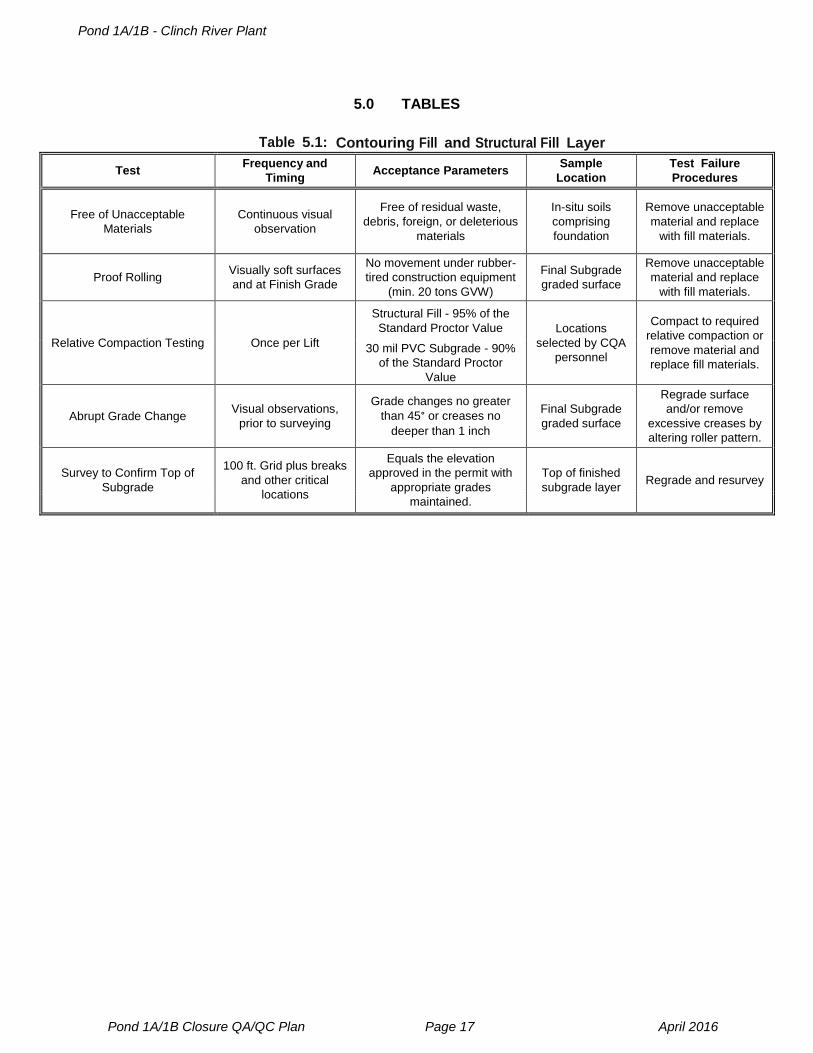
Quality assurance criteria for contouring fill and structural fill shall include the following
and are listed in Table 5.1:
Relative compaction testing of each lift of contouring or structural fill in
accordance to ASTM D6938.
The final subgrade surface will be visually inspected by the CQA Personnel and
proofrolled to verify a stable in-situ foundation exists prior to geosynthetic
installation.
The finished subgrade surface will be firm, uniform, and consistent with the
design lines and grades.
4.02 Cap System Construction
The cap system includes sequentially 30 mil PVC geomembrane, an infiltration drainage layer
(Geocomposite Drainage Net), and vegetative cover soils, as shown on the plans.
Construction of the cap system will be performed in accordance with this QA/QC Plan.
4.02.1 Pre Construction Testing
The cap system should be tested for puncture resistance prior to construction in
general accordance with ASTM D5514 “Standard Test Method for Large Scale
Hydrostatic Puncture Testing of Geosynthetics, Procedure C”. In accordance with
ASTM D5514, a 2-ft by 2-ft geomembrane sample over laid with the geocomposite
sample shall be compressed between the ash subgrade bottom layer and the cover
soil upper layer. The fly ash shall be compacted in the lower box to establish a firm
smooth subgrade. Cover soil placed in the upper box shall be a compacted 18” lift to
approximately 90 percent of the standard proctor (ASTM D698).
Once the testing apparatus is set up; first a 5-psi pressure will be applied to simulate
Pond 1A/1B - Clinch River Plant
Pond 1A/1B Closure QA/ QC Plan Page 8 April 2016
the load induced by the dozer and sustained for approximately 7 hours. Finally, the
pressure should be increased to 7 psi to simulate the static load of additional
placement of topsoil cover soil for approximately 20 hours. Upon completion of the
test, the geomembrane shall be visually inspected for punctures. The test is
considered passed if there are no punctures found in the geomembrane.
The cover soil sample shall be taken from the project borrow site and shall contain
particle sizes up to the maximum allowable per the construction specifications. The
largest particle contained in the sample shall be in direct contact with the
geomembrane. The largest particle size that undergoes a successful puncture
resistance test will determine the maximum particle size approved for this project. A
test shall be ran for each borrow source or if soils within a borrow source significantly
change.
4.03 30 mil PVC Geomembrane Installation
The final subgrade surface will be covered with an approved geomembrane. The
geomembrane serves as the principal hydraulic barrier to infiltration in the cap system and will
be installed in accordance with project construction requirements. All geomembrane
installation activities will be monitored on a daily basis by CQA Personnel.
4.03.1 Material Specifications
Quality assurance activities for the geomembrane material consist of obtaining written
documentation and test results from the synthetic liner manufacturer that the supplied
geomembrane liner panels comply with the minimum specifications for a 30 mil PVC
liner pursuant to ASTM D7176 PVC Material Specifications. Prior to or coincident with
shipment of geomembrane to the project site, the QA Officer shall review and approve
submittals from the Geomembrane Manufacturer which shall include:
1. Geomembrane Manufacturer's geomembrane specification sheets;
2. Geomembrane Manufacturer's Quality Control Certificates; and,
3. Other information required by the construction requirements.
No geomembrane shall be installed until the QA Officer has reviewed all certifications
and supporting test data and determined that the geomembrane furnished for the
project is acceptable for use.
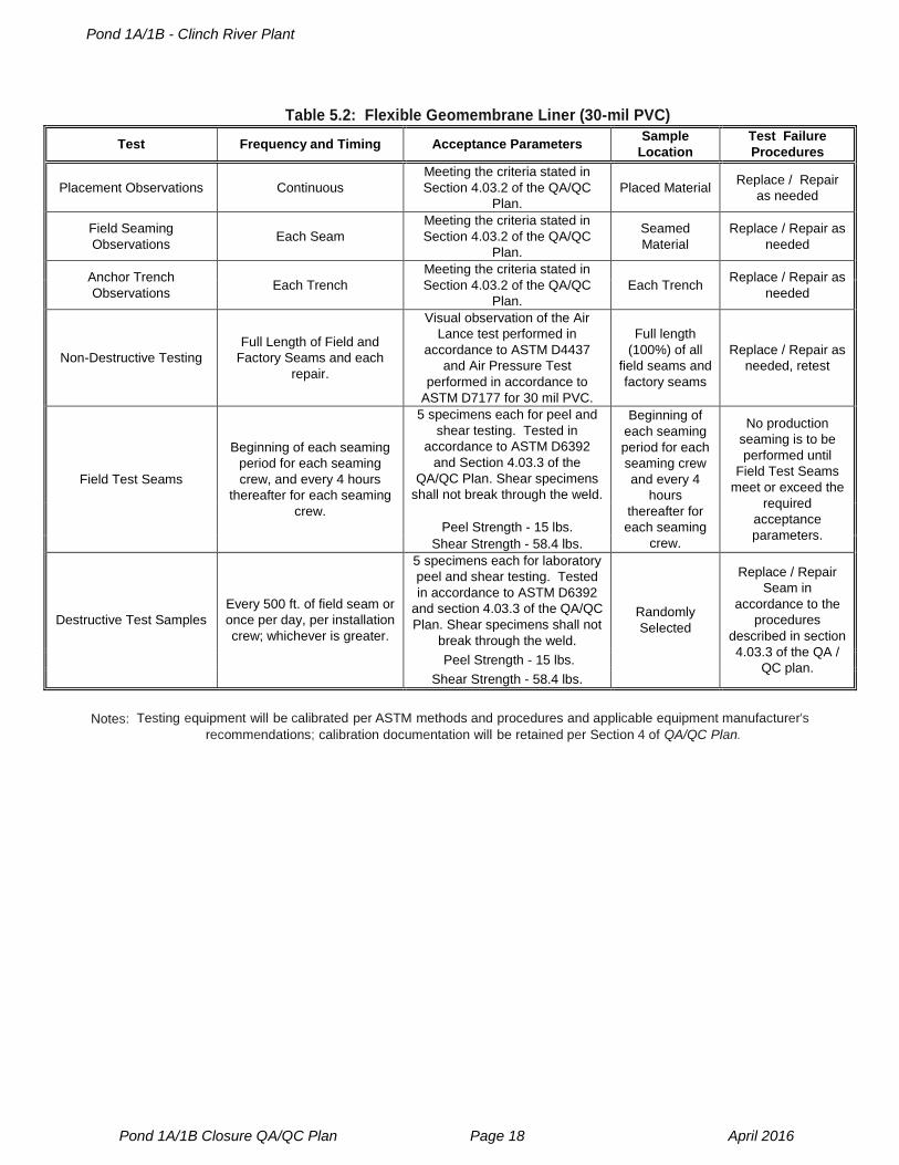
4.03.2 30 mil PVC Installation Inspections
Installation of the 30 mil PVC geomembrane involves the placement of the liner panels,
field seaming of adjacent panels together, repairs, non-destructive testing, anchoring
of the geosynthetics’ perimeter in trenches, and geosynthetic attachment to
penetrations. Quality assurance inspection for liner installation primarily consists of
the visual examination of these activities as described in the following paragraphs and
as listed in Table 5.2:
Quality assurance inspection of 30 mil PVC placement includes:
1. Final inspection for imperfections in the subgrade surface and observe repairs.
2. Observe that proper procedures are followed during 30 mil PVC geomembrane
layout; including, but not limited to, the weather conditions and panel layout
Pond 1A/1B - Clinch River Plant
Pond 1A/1B Closure QA/ QC Plan Page 9 April 2016
order.
3. Visually inspect the entire surface of each panel for tears, punctures, etc. Any
defects shall be marked for repair.
4. Observe that temporary anchorage is adequate to prevent shifting during
seaming.
Quality assurance inspection of 30 mil PVC field seaming includes observations to
verify that:
1. The 30 mil PVC panel is free from dirt, dust, and moisture.
2. Weather conditions are acceptable for seaming.
3. The 30 mil PVC geomembrane is not damaged during seaming process.
Quality assurance inspection of 30 mil geomembrane anchors and penetration
attachments includes observations to verify that:
1. Anchor trench depths, widths, and locations are as shown on the plans.
2. Trench surface and trench backfill are free of sharp edges and jagged rocks.
3. Anchor Trench backfill is compacted to 95% of the standard Proctor value.
4. The geomembrane is properly installed in the trench or to the penetration.
5. Backfilling and compaction operations do not damage the geomembrane.
In addition to the above visual inspections, the factory and field fabricated seams shall
be tested as follows:
1. All factory seams shall be non-destructively tested, by specified methods,
either at the factory or in the field after installation.
2. All field seams shall be non-destructively tested, by means of an air lance or
air pressure testing, over their full length in accordance with Table 5.2. All
areas where the seam is discontinuous shall be marked for repair, repaired by
patching, and retested.
3. When seaming by thermal fusion (i.e., using a hot wedge or hot air welder),
each seaming apparatus shall be tested by constructing and testing field test
seams for peel and shear at the beginning of each seaming period and at least
once every four hours thereafter for each seaming crew used each day. Field
test seams shall meet the requirements set forth in section 4.03.3. When
seaming by chemical fusion or adhesion, no seaming apparatus is used, and;
therefore, field test seams are not applicable and shall not be constructed.
4. Destructive test seam sampling for laboratory peel and shear testing shall be
performed at the frequencies listed in Table 5.2. The cut-out sections shall be
a minimum of 12 inches wide by 40 inches long with the seam centered length-
wise. The CQA Personnel shall randomly locate the sampling location and
shall not inform the seaming crew in advance of the location. All holes in the
geomembrane resulting from sampling shall be immediately repaired by
patching and non-destructively tested.
4.03.3 Destructive Testing
Destructive testing includes peel and shear testing of the field test seam samples and
the destructive test seam samples. Peel and shear tests shall be conducted in
accordance with the test methods listed in Table 5.2. Laboratory samples shall be 12
inches by 18 inches in size and labeled with the sample date, time, location,
equipment, and operator. Samples shall be shipped to the laboratory in containers
Pond 1A/1B - Clinch River Plant
Pond 1A/1B Closure QA/ QC Plan Page 10 April 2016
that prevent deformation of the samples prior to testing. For each seam sample
(including both field test seams and destructive test seams), five specimens for shear
seam strength and five specimens for peel strength shall be tested. To be acceptable,
the average of the peak loads recorded for the five specimens must meet the minimum
seam strength criteria listed in Table 5.2.
For production field seams that fail testing, the seam shall be patched between the
failed location and any passed test locations or the installer shall retrace the seam to
an intermediate location (at least ten feet from the failed test location), sample, and
retest. If this sample passes, then the seam shall be patched between the
intermediate location and the original failed location. If the test fails, then the process
is repeated. In all cases, acceptable seams shall be bounded by two passed test
locations.
4.04 Infiltration Drainage Layer Construction
The purpose of the infiltration drainage layer is to provide drainage of any precipitation that
percolates through the cover soil. It is comprised of a geocomposite drainage net (GDN) and
shall be constructed in accordance with project construction requirements and all installation
activities will be monitored on a daily basis by CQA Personnel.
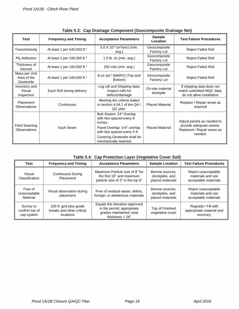
4.04.1 Geocomposite Drainage Net
The geocomposite drainage net (GDN) will consist of a high density polyethylene
(HDPE) geonet with nonwoven, needle-punched geotextiles heat-bonded to its upper
and lower surfaces.
The geocomposite drainage net manufactures quality control certificates shall verify
the following properties using the test method, frequency, and minimum value listed in
Table 5.3.
1. Transmissivity;
2. Ply Adhesion;
3. Thickness of the geonet; and,
4. Mass per unit area of geotextile.
Prior to or coincident with shipment of geocomposite drainage net to the project site,
the QA Officer shall review and approve submittals from the geocomposite drainage
net manufacturer which shall include:
1. Geocomposite drainage net manufacturer's specification sheet(s);
2. Geocomposite drainage net manufacturer's quality control (MQC) certificates;
and,
3. Other information required by the technical specifications.
No geocomposite drainage net shall be installed until the QA Officer has reviewed all
certifications and supporting test data and determined that the geocomposite drainage
net furnished for the project is acceptable for use.
All geocomposite drainage net delivery, handling, and unloading shall be performed in
the presence of the CQA Personnel. During unloading, the contractor and CQA
Personnel shall conduct an inspection of all delivered geocomposite drainage net for
Pond 1A/1B - Clinch River Plant
Pond 1A/1B Closure QA/ QC Plan Page 11 April 2016
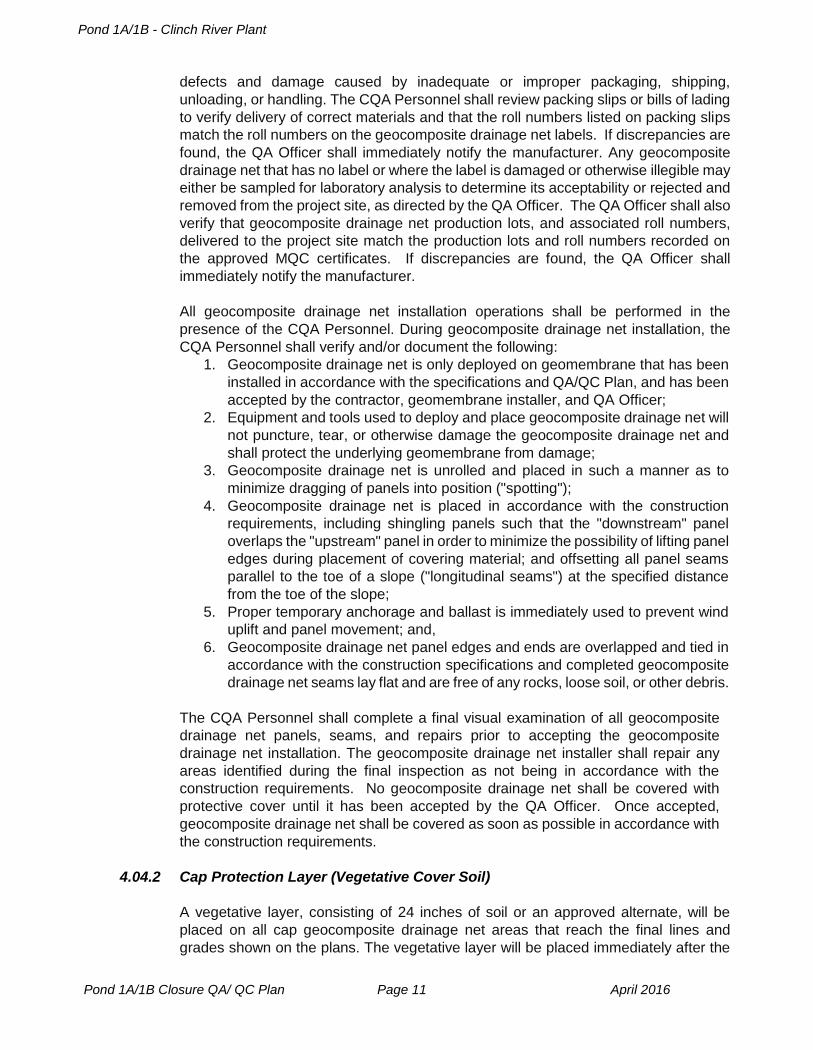
defects and damage caused by inadequate or improper packaging, shipping,
unloading, or handling. The CQA Personnel shall review packing slips or bills of lading
to verify delivery of correct materials and that the roll numbers listed on packing slips
match the roll numbers on the geocomposite drainage net labels. If discrepancies are
found, the QA Officer shall immediately notify the manufacturer. Any geocomposite
drainage net that has no label or where the label is damaged or otherwise illegible may
either be sampled for laboratory analysis to determine its acceptability or rejected and
removed from the project site, as directed by the QA Officer. The QA Officer shall also
verify that geocomposite drainage net production lots, and associated roll numbers,
delivered to the project site match the production lots and roll numbers recorded on
the approved MQC certificates. If discrepancies are found, the QA Officer shall
immediately notify the manufacturer.
All geocomposite drainage net installation operations shall be performed in the
presence of the CQA Personnel. During geocomposite drainage net installation, the
CQA Personnel shall verify and/or document the following:
1. Geocomposite drainage net is only deployed on geomembrane that has been
installed in accordance with the specifications and QA/QC Plan, and has been
accepted by the contractor, geomembrane installer, and QA Officer;
2. Equipment and tools used to deploy and place geocomposite drainage net will
not puncture, tear, or otherwise damage the geocomposite drainage net and
shall protect the underlying geomembrane from damage;
3. Geocomposite drainage net is unrolled and placed in such a manner as to
minimize dragging of panels into position ("spotting");
4. Geocomposite drainage net is placed in accordance with the construction
requirements, including shingling panels such that the "downstream" panel
overlaps the "upstream" panel in order to minimize the possibility of lifting panel
edges during placement of covering material; and offsetting all panel seams
parallel to the toe of a slope ("longitudinal seams") at the specified distance
from the toe of the slope;
5. Proper temporary anchorage and ballast is immediately used to prevent wind
uplift and panel movement; and,
6. Geocomposite drainage net panel edges and ends are overlapped and tied in
accordance with the construction specifications and completed geocomposite
drainage net seams lay flat and are free of any rocks, loose soil, or other debris.
The CQA Personnel shall complete a final visual examination of all geocomposite
drainage net panels, seams, and repairs prior to accepting the geocomposite
drainage net installation. The geocomposite drainage net installer shall repair any
areas identified during the final inspection as not being in accordance with the
construction requirements. No geocomposite drainage net shall be covered with
protective cover until it has been accepted by the QA Officer. Once accepted,
geocomposite drainage net shall be covered as soon as possible in accordance with
the construction requirements.
4.04.2 Cap Protection Layer (Vegetative Cover Soil)
A vegetative layer, consisting of 24 inches of soil or an approved alternate, will be
placed on all cap geocomposite drainage net areas that reach the final lines and
grades shown on the plans. The vegetative layer will be placed immediately after the

Pond 1A/1B - Clinch River Plant
Pond 1A/1B Closure QA/ QC Plan Page 12 April 2016
geocomposite drainage net is installed in the completed areas of each facility
development phase. The vegetative layer will be constructed using soils obtained from
on-site and off-site borrow sources. The cap erosion layer shall consist of a maximum
particle size of 9 inches for the first 18 inches and a maximum particle size of 3 inches
for the top 6 inches.
Quality assurance criteria for the vegetative layer are listed in Table 5.4 and also
include the following:
Materials (e.g., topsoil, fertilizer, seed) provided meet construction specifications;
Materials are placed as specified;
During the construction care period (a minimum of one full growing season),
erosion protection is to be maintained; and,
If required, periodic irrigation will be utilized to produce satisfactory growth.
4.05 Drainage Collection System
A system of drainage collection channels and pipes will be installed, as indicated in the
Construction Specifications and Project Drawings, to collect and divert surface water. The
drainage collection systems will be constructed in accordance with the Construction
Specifications and Project Drawings.
Quality assurance criteria for the drainage system will include visual inspection and testing
of the following components and materials throughout the construction of drainage collection
systems:
12 oz. Non-Woven Geotextile
Aggregate
Rip Rap and Grouted Rip Rap
Piping Systems
Concrete
Gabion Mattress Installation
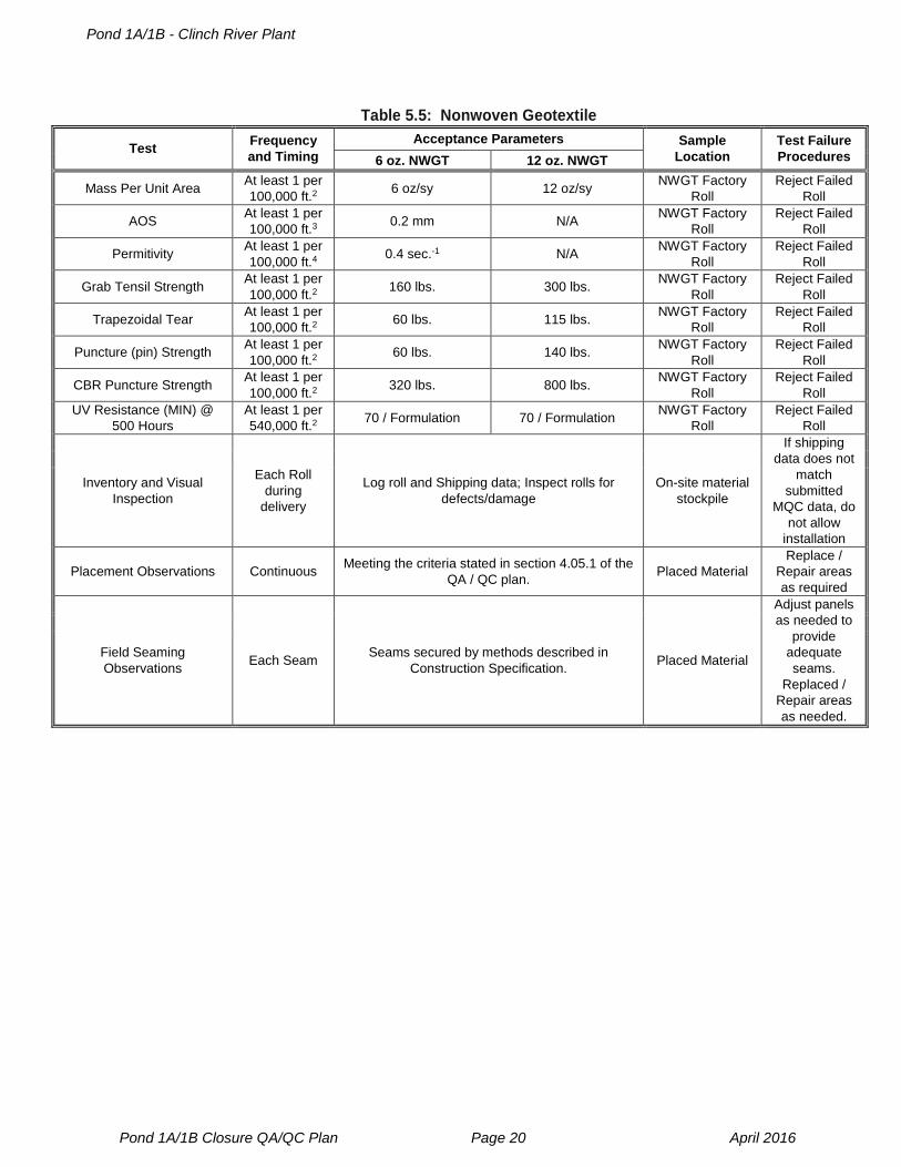
4.05.1 12 oz. Nonwoven Geotextile
12 oz. Nonwoven Geotextile (NWGT) shall be installed in accordance with the
Construction Specifications and Project Drawings.
The 12 oz. nonwoven geotextile quality control certificates shall verify the following
properties using the test method, frequency, and minimum values listed in Table 5.5.
1. Mass per Unit Area
2. Grab Tensile Strength
3. Trapezoid Tear
4. Puncture Strength
5. CBR Puncture Strength
6. UV Resistance (MIN) @ 500 Hours
Prior to or coincident with shipment of 12 oz. nonwoven geotextile to the project site,
the QA Officer shall review and approve submittals from the geotextile manufacturer
which shall include:
1. 12 oz. nonwoven geotextile manufacturer’s specification sheet(s);
2. 12 oz. nonwoven geotextile manufacturer’s quality control (MQC) certificates;
Pond 1A/1B - Clinch River Plant
Pond 1A/1B Closure QA/ QC Plan Page 13 April 2016
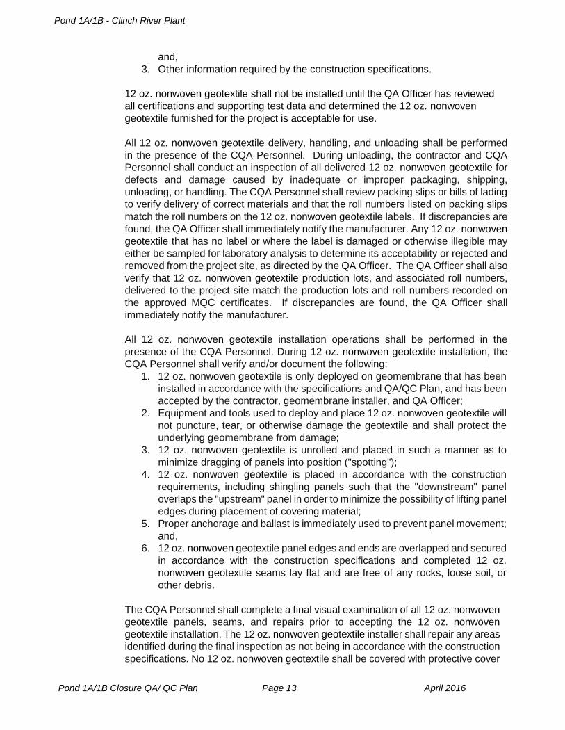
and,
3. Other information required by the construction specifications.
12 oz. nonwoven geotextile shall not be installed until the QA Officer has reviewed
all certifications and supporting test data and determined the 12 oz. nonwoven
geotextile furnished for the project is acceptable for use.
All 12 oz. nonwoven geotextile delivery, handling, and unloading shall be performed
in the presence of the CQA Personnel. During unloading, the contractor and CQA
Personnel shall conduct an inspection of all delivered 12 oz. nonwoven geotextile for
defects and damage caused by inadequate or improper packaging, shipping,
unloading, or handling. The CQA Personnel shall review packing slips or bills of lading
to verify delivery of correct materials and that the roll numbers listed on packing slips
match the roll numbers on the 12 oz. nonwoven geotextile labels. If discrepancies are
found, the QA Officer shall immediately notify the manufacturer. Any 12 oz. nonwoven
geotextile that has no label or where the label is damaged or otherwise illegible may
either be sampled for laboratory analysis to determine its acceptability or rejected and
removed from the project site, as directed by the QA Officer. The QA Officer shall also
verify that 12 oz. nonwoven geotextile production lots, and associated roll numbers,
delivered to the project site match the production lots and roll numbers recorded on
the approved MQC certificates. If discrepancies are found, the QA Officer shall
immediately notify the manufacturer.
All 12 oz. nonwoven geotextile installation operations shall be performed in the
presence of the CQA Personnel. During 12 oz. nonwoven geotextile installation, the
CQA Personnel shall verify and/or document the following:
1. 12 oz. nonwoven geotextile is only deployed on geomembrane that has been
installed in accordance with the specifications and QA/QC Plan, and has been
accepted by the contractor, geomembrane installer, and QA Officer;
2. Equipment and tools used to deploy and place 12 oz. nonwoven geotextile will
not puncture, tear, or otherwise damage the geotextile and shall protect the
underlying geomembrane from damage;
3. 12 oz. nonwoven geotextile is unrolled and placed in such a manner as to
minimize dragging of panels into position ("spotting");
4. 12 oz. nonwoven geotextile is placed in accordance with the construction
requirements, including shingling panels such that the "downstream" panel
overlaps the "upstream" panel in order to minimize the possibility of lifting panel
edges during placement of covering material;
5. Proper anchorage and ballast is immediately used to prevent panel movement;
and,
6. 12 oz. nonwoven geotextile panel edges and ends are overlapped and secured
in accordance with the construction specifications and completed 12 oz.
nonwoven geotextile seams lay flat and are free of any rocks, loose soil, or
other debris.
The CQA Personnel shall complete a final visual examination of all 12 oz. nonwoven
geotextile panels, seams, and repairs prior to accepting the 12 oz. nonwoven
geotextile installation. The 12 oz. nonwoven geotextile installer shall repair any areas
identified during the final inspection as not being in accordance with the construction
specifications. No 12 oz. nonwoven geotextile shall be covered with protective cover
Pond 1A/1B - Clinch River Plant
Pond 1A/1B Closure QA/ QC Plan Page 14 April 2016
until it has been accepted by the QA Officer. Once accepted, 12 oz. nonwoven
geotextile shall be covered as soon as possible in accordance with the construction
requirements.
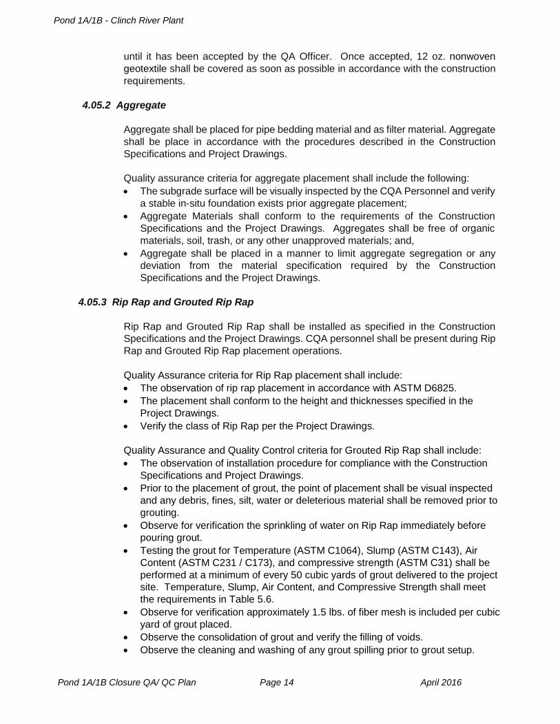
4.05.2 Aggregate
Aggregate shall be placed for pipe bedding material and as filter material. Aggregate
shall be place in accordance with the procedures described in the Construction
Specifications and Project Drawings.
Quality assurance criteria for aggregate placement shall include the following:
The subgrade surface will be visually inspected by the CQA Personnel and verify
a stable in-situ foundation exists prior aggregate placement;
Aggregate Materials shall conform to the requirements of the Construction
Specifications and the Project Drawings. Aggregates shall be free of organic
materials, soil, trash, or any other unapproved materials; and,
Aggregate shall be placed in a manner to limit aggregate segregation or any
deviation from the material specification required by the Construction
Specifications and the Project Drawings.
4.05.3 Rip Rap and Grouted Rip Rap
Rip Rap and Grouted Rip Rap shall be installed as specified in the Construction
Specifications and the Project Drawings. CQA personnel shall be present during Rip
Rap and Grouted Rip Rap placement operations.
Quality Assurance criteria for Rip Rap placement shall include:
The observation of rip rap placement in accordance with ASTM D6825.
The placement shall conform to the height and thicknesses specified in the
Project Drawings.
Verify the class of Rip Rap per the Project Drawings.
Quality Assurance and Quality Control criteria for Grouted Rip Rap shall include:
The observation of installation procedure for compliance with the Construction
Specifications and Project Drawings.
Prior to the placement of grout, the point of placement shall be visual inspected
and any debris, fines, silt, water or deleterious material shall be removed prior to
grouting.
Observe for verification the sprinkling of water on Rip Rap immediately before
pouring grout.
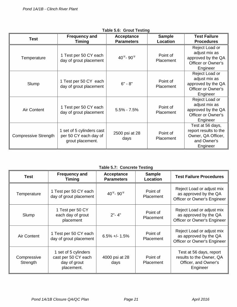
Testing the grout for Temperature (ASTM C1064), Slump (ASTM C143), Air
Content (ASTM C231 / C173), and compressive strength (ASTM C31) shall be
performed at a minimum of every 50 cubic yards of grout delivered to the project
site. Temperature, Slump, Air Content, and Compressive Strength shall meet
the requirements in Table 5.6.
Observe for verification approximately 1.5 lbs. of fiber mesh is included per cubic
yard of grout placed.
Observe the consolidation of grout and verify the filling of voids.
Observe the cleaning and washing of any grout spilling prior to grout setup.
Pond 1A/1B - Clinch River Plant
Pond 1A/1B Closure QA/ QC Plan Page 15 April 2016
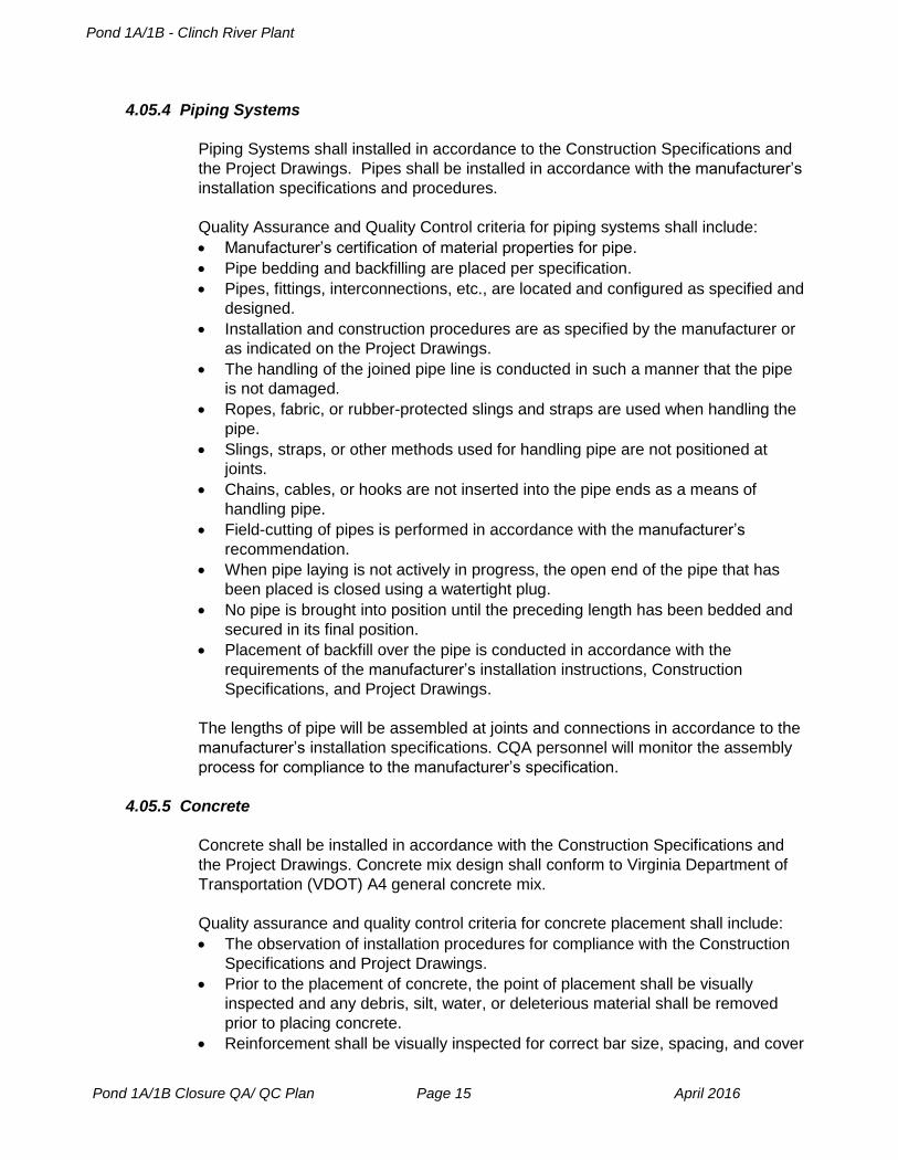
4.05.4 Piping Systems
Piping Systems shall installed in accordance to the Construction Specifications and
the Project Drawings. Pipes shall be installed in accordance with the manufacturer’s
installation specifications and procedures.
Quality Assurance and Quality Control criteria for piping systems shall include:
Manufacturer’s certification of material properties for pipe.
Pipe bedding and backfilling are placed per specification.
Pipes, fittings, interconnections, etc., are located and configured as specified and
designed.
Installation and construction procedures are as specified by the manufacturer or
as indicated on the Project Drawings.
The handling of the joined pipe line is conducted in such a manner that the pipe
is not damaged.
Ropes, fabric, or rubber-protected slings and straps are used when handling the
pipe.
Slings, straps, or other methods used for handling pipe are not positioned at
joints.
Chains, cables, or hooks are not inserted into the pipe ends as a means of
handling pipe.
Field-cutting of pipes is performed in accordance with the manufacturer’s
recommendation.
When pipe laying is not actively in progress, the open end of the pipe that has
been placed is closed using a watertight plug.
No pipe is brought into position until the preceding length has been bedded and
secured in its final position.
Placement of backfill over the pipe is conducted in accordance with the
requirements of the manufacturer’s installation instructions, Construction
Specifications, and Project Drawings.
The lengths of pipe will be assembled at joints and connections in accordance to the
manufacturer’s installation specifications. CQA personnel will monitor the assembly
process for compliance to the manufacturer’s specification.
4.05.5 Concrete
Concrete shall be installed in accordance with the Construction Specifications and
the Project Drawings. Concrete mix design shall conform to Virginia Department of
Transportation (VDOT) A4 general concrete mix.
Quality assurance and quality control criteria for concrete placement shall include:
The observation of installation procedures for compliance with the Construction
Specifications and Project Drawings.
Prior to the placement of concrete, the point of placement shall be visually
inspected and any debris, silt, water, or deleterious material shall be removed
prior to placing concrete.
Reinforcement shall be visually inspected for correct bar size, spacing, and cover
Pond 1A/1B - Clinch River Plant
Pond 1A/1B Closure QA/ QC Plan Page 16 April 2016
prior to concrete placement.
Testing the concrete for Temperature (ASTM C1064), Slump (ASTM C143), Air
Content (ASTM C231 / C173), and compressive strength (ASTM C31) shall be
performed at a minimum of every 50 cubic yards of concrete delivered to the
project site. Temperature, Slump, Air Content, and Compressive Strength shall
meet the requirements in Table 5.7.
4.05.6 Gabion Mattress Installation
Gabion mattresses shall be installed in accordance with the Construction
Specifications, manufacturer installation specifications, and the Project Drawings.
Gabion mattresses shall be Maccaferri (or approved equal) galvanized gabion
mattresses and filled with sound aggregate or rock fragments imported to the site
from a commercial quarry. Fill aggregate shall not consist of any demolished
concrete materials.
Quality assurance and quality control criteria for gabion mattress installation shall
include:
The observation of the installation process for compliance with the Construction
Specifications and the Project Drawings.
Gabion mattresses comply with the manufacturer’s specifications.
The observation of gabion mattress subgrade is in compliance with section
4.01.1 Contouring and Structural Fill Requirements.
Gabion anchor stakes shall be visually inspected for spacing and dimension
requirements as specified in the Project Drawings and the manufacturer’s
specifications.
Fill aggregate used for gabion mattresses fill shall comply with the aggregate
size for the lower diversion channel and the upper diversion channel as specified
by the Construction Requirements and the Project Drawings.
Pond 1A/1B - Clinch River Plant
Pond 1A/1B Closure QA/QC Plan Page 17 April 2016
5.0 TABLES
Table 5.1: Contouring Fill and Structural Fill Layer
Test Frequency and
Timing Acceptance Parameters
Sample
Location
Test Failure
Procedures
Free of Unacceptable
Materials
Continuous visual
observation
Free of residual waste,
debris, foreign, or deleterious
materials
In-situ soils
comprising
foundation
Remove unacceptable
material and replace
with fill materials.
Proof Rolling Visually soft surfaces
and at Finish Grade
No movement under rubber-
tired construction equipment
(min. 20 tons GVW)
Final Subgrade
graded surface
Remove unacceptable
material and replace
with fill materials.
Relative Compaction Testing Once per Lift
Structural Fill - 95% of the
Standard Proctor Value Locations
selected by CQA
personnel
Compact to required
relative compaction or
remove material and
replace fill materials.
30 mil PVC Subgrade - 90%
of the Standard Proctor
Value
Abrupt Grade Change Visual observations,
prior to surveying
Grade changes no greater
than 45° or creases no
deeper than 1 inch
Final Subgrade
graded surface
Regrade surface
and/or remove
excessive creases by
altering roller pattern.
Survey to Confirm Top of
Subgrade
100 ft. Grid plus breaks
and other critical
locations
Equals the elevation
approved in the permit with
appropriate grades
maintained.
Top of finished
subgrade layer Regrade and resurvey
Pond 1A/1B - Clinch River Plant
Pond 1A/1B Closure QA/QC Plan Page 18 April 2016
Table 5.2: Flexible Geomembrane Liner (30-mil PVC)
Test Frequency and Timing Acceptance Parameters Sample
Location
Test Failure
Procedures
Placement Observations Continuous
Meeting the criteria stated in
Section 4.03.2 of the QA/QC
Plan.
Placed Material Replace / Repair
as needed
Field Seaming
Observations Each Seam
Meeting the criteria stated in
Section 4.03.2 of the QA/QC
Plan.
Seamed
Material
Replace / Repair as
needed
Anchor Trench
Observations Each Trench
Meeting the criteria stated in
Section 4.03.2 of the QA/QC
Plan.
Each Trench Replace / Repair as
needed
Non-Destructive Testing
Full Length of Field and
Factory Seams and each
repair.
Visual observation of the Air
Lance test performed in
accordance to ASTM D4437
and Air Pressure Test
performed in accordance to
ASTM D7177 for 30 mil PVC.
Full length
(100%) of all
field seams and
factory seams
Replace / Repair as
needed, retest
Field Test Seams
Beginning of each seaming
period for each seaming
crew, and every 4 hours
thereafter for each seaming
crew.
5 specimens each for peel and
shear testing. Tested in
accordance to ASTM D6392
and Section 4.03.3 of the
QA/QC Plan. Shear specimens
shall not break through the weld.
Beginning of
each seaming
period for each
seaming crew
and every 4
hours
thereafter for
each seaming
crew.
No production
seaming is to be
performed until
Field Test Seams
meet or exceed the
required
acceptance
parameters.
Peel Strength - 15 lbs.
Shear Strength - 58.4 lbs.
Destructive Test Samples
Every 500 ft. of field seam or
once per day, per installation
crew; whichever is greater.
5 specimens each for laboratory
peel and shear testing. Tested
in accordance to ASTM D6392
and section 4.03.3 of the QA/QC
Plan. Shear specimens shall not
break through the weld.
Randomly
Selected
Replace / Repair
Seam in
accordance to the
procedures
described in section
4.03.3 of the QA /
QC plan. Peel Strength - 15 lbs.
Shear Strength - 58.4 lbs.
Notes: Testing equipment will be calibrated per ASTM methods and procedures and applicable equipment manufacturer's
recommendations; calibration documentation will be retained per Section 4 of QA/QC Plan.
Pond 1A/1B - Clinch River Plant
Pond 1A/1B Closure QA/QC Plan Page 19 April 2016
Table 5.3: Cap Drainage Component (Geocomposite Drainage Net)
Test Frequency and Timing Acceptance Parameters Sample
Location Test Failure Procedures
Transmissivity At least 1 per 540,000 ft.2 5.0 X 10⁻⁴ (m2/sec) (min.
avg.)
Geocomposite
Factory Lot Reject Failed Roll
Ply Adhesion At least 1 per 100,000 ft.2 1.0 lb. /in (min. avg.) Geocomposite
Factory Lot Reject Failed Roll
Thickness of
Geonet At least 1 per 100,000 ft.2 250 mils (min. avg.)
Geocomposite
Factory Lot Reject Failed Roll
Mass per Unit
Area of the
Geotextile
At least 1 per 100,000 ft.2 8 oz./yd.2 (MARV) (Top and
Bottom)
Geocomposite
Factory Lot Reject Failed Roll
Inventory and
Visual
Inspection
Each Roll during delivery
Log roll and Shipping data;
Inspect rolls for
defects/damage
On-site material
stockpile
If shipping data does not
match submitted MQC data,
do not allow installation
Placement
Observations Continuous
Meeting the criteria stated
in section 4.04.1 of the QA /
QC plan.
Placed Material Replace / Repair areas as
required
Field Seaming
Observations Each Seam
Butt Seams: 24" Overlap
with ties spaced every 6
inches
Placed Material
Adjust panels as needed to
provide adequate seams.
Replaced / Repair areas as
needed.
Panel Overlap: 3-6" overlap
with ties spaced every 5 ft.
Covering Geotextile shall be
mechanically seamed.
Table 5.4: Cap Protection Layer (Vegetative Cover Soil)
Test Frequency and Timing Acceptance Parameters Sample Location Test Failure Procedures
Visual
Classification
Continuous During
Placement
Maximum Particle size of 9" for
the first 18" and maximum
particle size of 3" in the top 6"
Borrow sources,
stockpiles, and
placed materials
Reject unacceptable
materials and use
acceptable materials
Free of
Unacceptable
Material
Visual observation during
placement
Free of residual waste, debris,
foreign, or deleterious materials
Borrow sources,
stockpiles, and
placed materials
Reject unacceptable
materials and use
acceptable materials
Survey to
confirm top of
cap system
100 ft. grid plus grade
breaks and other critical
locations
Equals the elevation approved
in the permit; appropriate
grades maintained; total
thickness = 24"
Top of Finished
vegetative cover
Regrade / Fill with
appropriate material and
resurvey.
Pond 1A/1B - Clinch River Plant
Pond 1A/1B Closure QA/QC Plan Page 20 April 2016
Table 5.5: Nonwoven Geotextile
Test Frequency
and Timing
Acceptance Parameters Sample
Location
Test Failure
Procedures 6 oz. NWGT 12 oz. NWGT
Mass Per Unit Area At least 1 per
100,000 ft.2 6 oz/sy 12 oz/sy
NWGT Factory
Roll
Reject Failed
Roll
AOS At least 1 per
100,000 ft.3 0.2 mm N/A
NWGT Factory
Roll
Reject Failed
Roll
Permitivity At least 1 per
100,000 ft.4 0.4 sec.-1 N/A
NWGT Factory
Roll
Reject Failed
Roll
Grab Tensil Strength At least 1 per
100,000 ft.2 160 lbs. 300 lbs.
NWGT Factory
Roll
Reject Failed
Roll
Trapezoidal Tear At least 1 per
100,000 ft.2 60 lbs. 115 lbs.
NWGT Factory
Roll
Reject Failed
Roll
Puncture (pin) Strength At least 1 per
100,000 ft.2 60 lbs. 140 lbs.
NWGT Factory
Roll
Reject Failed
Roll
CBR Puncture Strength At least 1 per
100,000 ft.2 320 lbs. 800 lbs.
NWGT Factory
Roll
Reject Failed
Roll
UV Resistance (MIN) @
500 Hours
At least 1 per
540,000 ft.2 70 / Formulation 70 / Formulation
NWGT Factory
Roll
Reject Failed
Roll
Inventory and Visual
Inspection
Each Roll
during
delivery
Log roll and Shipping data; Inspect rolls for
defects/damage
On-site material
stockpile
If shipping
data does not
match
submitted
MQC data, do
not allow
installation
Placement Observations Continuous Meeting the criteria stated in section 4.05.1 of the
QA / QC plan. Placed Material
Replace /
Repair areas
as required
Field Seaming
Observations Each Seam
Seams secured by methods described in
Construction Specification. Placed Material
Adjust panels
as needed to
provide
adequate
seams.
Replaced /
Repair areas
as needed.
Pond 1A/1B - Clinch River Plant
Pond 1A/1B Closure QA/QC Plan Page 21 April 2016
Table 5.6: Grout Testing
Test Frequency and
Timing
Acceptance
Parameters
Sample
Location
Test Failure
Procedures
Temperature 1 Test per 50 CY each
day of grout placement 40°F- 90°F
Point of
Placement
Reject Load or
adjust mix as
approved by the QA
Officer or Owner's
Engineer
Slump 1 Test per 50 CY each
day of grout placement 6" - 8"
Point of
Placement
Reject Load or
adjust mix as
approved by the QA
Officer or Owner's
Engineer
Air Content 1 Test per 50 CY each
day of grout placement 5.5% - 7.5%
Point of
Placement
Reject Load or
adjust mix as
approved by the QA
Officer or Owner's
Engineer
Compressive Strength
1 set of 5 cylinders cast
per 50 CY each day of
grout placement.
2500 psi at 28
days
Point of
Placement
Test at 56 days,
report results to the
Owner, QA Officer,
and Owner's
Engineer
Table 5.7: Concrete Testing
Test Frequency and
Timing
Acceptance
Parameters
Sample
Location Test Failure Procedures
Temperature 1 Test per 50 CY each
day of grout placement 40°F- 90°F
Point of
Placement
Reject Load or adjust mix
as approved by the QA
Officer or Owner's Engineer
Slump
1 Test per 50 CY
each day of grout
placement
2"- 4" Point of
Placement
Reject Load or adjust mix
as approved by the QA
Officer or Owner's Engineer
Air Content 1 Test per 50 CY each
day of grout placement 6.5% +/- 1.5%
Point of
Placement
Reject Load or adjust mix
as approved by the QA
Officer or Owner's Engineer
Compressive
Strength
1 set of 5 cylinders
cast per 50 CY each
day of grout
placement.
4000 psi at 28
days
Point of
Placement
Test at 56 days, report
results to the Owner, QA
Officer, and Owner's
Engineer


![[List University Name] Quality Assurance Program ... Assurance Foms/University... · [List University Name] Quality Assurance Program Description Document ... Quality Assurance Program](https://img.pdfslide.net/doc/110x75/5ab8c3d37f8b9aa6018d08ac/list-university-name-quality-assurance-program-assurance-fomsuniversitylist.jpg)