Embed Size (px)
Citation preview
1
ATTITUDE CONTROL OF THE ASTEROID ORIGINS SATELLITE 1 (AOSAT 1)
Raviteja Nallapu,* Saumil Shah,† Erik Asphaug, ‡ and Jekan Thangavelautham§
Exploration of asteroids and small-bodies can provide valuable insight into the
origins of the solar system, into the origins of Earth and the origins of the build-
ing blocks of life. However, the low-gravity and unknown surface conditions of
asteroids presents a daunting challenge for surface exploration, manipulation
and for resource processing. This has resulted in the loss of several landers or
shortened missions. Fundamental studies are required to obtain better readings
of the material surface properties and physical models of these small bodies.
The Asteroid Origins Satellite 1 (AOSAT 1) is a CubeSat centrifuge laboratory
that spins at up to 4 rpm to simulate the milligravity conditions of sub 1 km as-
teroids. Such a laboratory will help to de-risk development and testing of land-
ing and resource processing technology for asteroids. Inside the laboratory are
crushed meteorites, the remains of asteroids. The laboratory is equipped with
cameras and actuators to perform a series of science experiments to better un-
derstand material properties and asteroid surface physics. These results will
help to improve our physics models of asteroids. The CubeSat has been de-
signed to be low-cost and contains 3-axis magnetorquers and a single reaction-
wheel to induce spin. In our work, we first analyze how the attitude control sys-
tem will de-tumble the spacecraft after deployment. Further analysis has been
conducted to analyze the impact and stability of the attitude control system to
shifting mass (crushed meteorites) inside the spacecraft as its spinning in its cen-
trifuge mode. These analyses been performed to bound the science payload mass
and identify fail-safe methods to guarantee spin stability and stop spinning when
commanded to do so. The spacecraft will need to remain stationary when trans-
mitting important science data to Earth and for conducting accretion experi-
ments. AOSAT 1 will be the first in a series of low-cost CubeSat centrifuges
that will be launched setting the stage for a larger, permanent, on-orbit centri-
fuge laboratory for experiments in planetary science, life sciences and manufac-
turing.
* PhD Student, Space and Terrestrial Robotic Exploration Laboratory, Arizona State University, 781 E. Terrace Mall,
Tempe, AZ. † GNC Engineer, United Launch Alliance (ULA), ‡ Professor and Ronald Greeley Chair of Planetary Science, Space and Terrestrial Robotic Exploration Laboratory,
Arizona State University, 781 E. Terrace Mall, Tempe, AZ § Assistant Professor, Space and Terrestrial Robotic Exploration Laboratory, Arizona State University, 781 E. Terrace
Mall, Tempe, AZ
(Preprint)
2
INTRODUCTION
Missions to asteroids and comets help us answer some of the fundamental questions about or-
igins of the solar system, earth and the building blocks of life. However, these missions present
unique challenges owing to their low gravity environments, since getting into an orbit around an
asteroid or landing is hard. Techniques like grappling can end up pushing rubble particles, while
landings might experience forces enough to attain bounce-off with escape velocities. These prob-
lems were observed in Hayabusa -11, Phillae
2, and Phobos missions
3. There is an important need
to gain fundamental understanding of asteroid physics, formation and material science to enable
ambitious future landing, sample return and resource-mining missions. What better way to pre-
pare for these missions by simulating asteroid surface conditions.
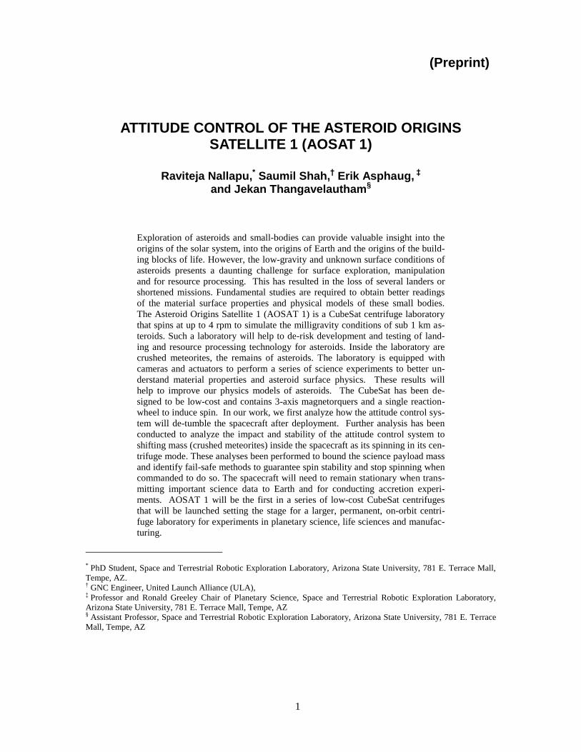
However, simulating asteroid surface conditions remains a formidable challenge. The chal-
lenge comes from simulating the low-gravity conditions. Figures 1 present some conventional
methods to simulate low-gravity conditions on earth. These include parabolic flight, use of neu-
tral buoyancy within large water tanks and drop towers. In a parabolic flight, an aircraft is ma-
neuvered to create brief periods of micro-gravity conditions last 10-20 seconds4. Neutral buoyan-
cy methods suspend objects in water, with buoyant attachments that compensates for the objects
mass5. Finally, drop towers contain a chamber that fall for 5-10 seconds enabling the contents of
the chamber to briefly experience microgravity conditions6. These conventional methods simulate
low-gravity conditions for too brief a time period or impose simulation artifacts that prevent cor-
relation with real asteroid surface conditions.
Figure 1. Methods to simulate low-gravity conditions include use of parabolic flight (left), neutral
buoyancy in large water tanks (center) and use of drop towers (right).
A promising solution to simulating low-gravity conditions is using a centrifuge operating in
Low-Earth Orbit7. The centrifuge consist of a mass m, spinning at a radius r, at an angular veloci-
ty ω, which create a centrifugal force of magnitude Fc=m r 2. The concept of a space centrifuge
is not new and has been a popular topic of science fiction. However, we have yet to see a habita-
tion centrifuge or centrifuge science laboratory operate in space. Our focus is to create a centri-
fuge science laboratory to simulate the surface conditions and the physics of small bodies.
We have proposed utilizing a 3U CubeSat to test the concept. CubeSats are emerging as low-
cost platform to perform space science and technology research. They offer the possibility of
short development times, wide use of Commercial-Off-the-Shelf Technologies (COTS), frequent
launches and training of graduate and undergraduate students. Our first CubeSat science labora-
tory mission is called Asteroid Origins Satellite-1 (AOSAT-1)8,17,18
. The spacecraft, a 3U, 34 cm
× 10 cm × 10 cm (size of a loaf of bread) will contain a science chamber that takes two-thirds of
the spacecraft volume and contain crushed meteorite. One third of the spacecraft contains the
spacecraft electronics, Guidance Navigation and Control (GNC), communications electronics and
the power system. GNC plays a critical part on the AOSAT-1 demonstrator mission and is the
focus of this paper. This paper discusses the GNC strategies used to develop the AOSAT-1
3
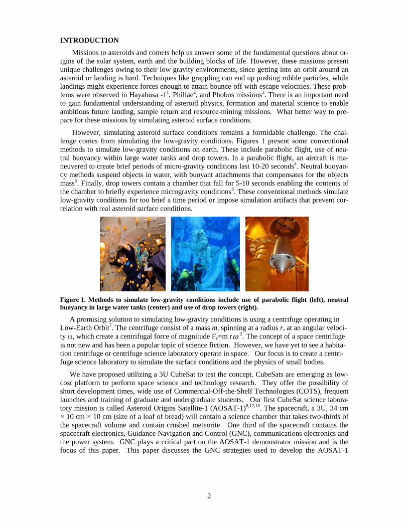
spacecraft. The spacecraft produces artificial gravity by spinning at 1 RPM as shown in Figure 2,
using magnetorquers and a reaction-wheel. This is sufficient to simulate the gravitational forces
experienced on a sub 1 km asteroid. A major advantage of a centrifuge science laboratory such as
AOSAT 1 is that it can simulate asteroid surface conditions without having to go to an asteroid,
which remains a long and expensive endeavor. These centrifuges can help use prepare for future
mission by testing new technologies under asteroid conditions.
Figure 2. AOSAT-1 Model with its spin axis.
We begin with an overview of the mission and concept of operations. We then move to out-
line attitude control requirements of the mission followed by presentation of the rigid-body equa-
tions of motion and the physics. A discussion on attitude determination of the spacecraft with
mass uncertainties is presented followed by simulation results of the expected GNC performance.
Finally, we conclude the paper with a summary of findings and future work.
MISSION
AOSAT-1 will be launched aboard a rocket resupply mission to the International Space Sta-
tion (ISS). The CubeSat will be deployed from ISS into a low earth orbit (LEO) at a 370-440 km
altitude. Each orbit is about 92 minutes long. The spacecraft upon deployment undergoes a man-
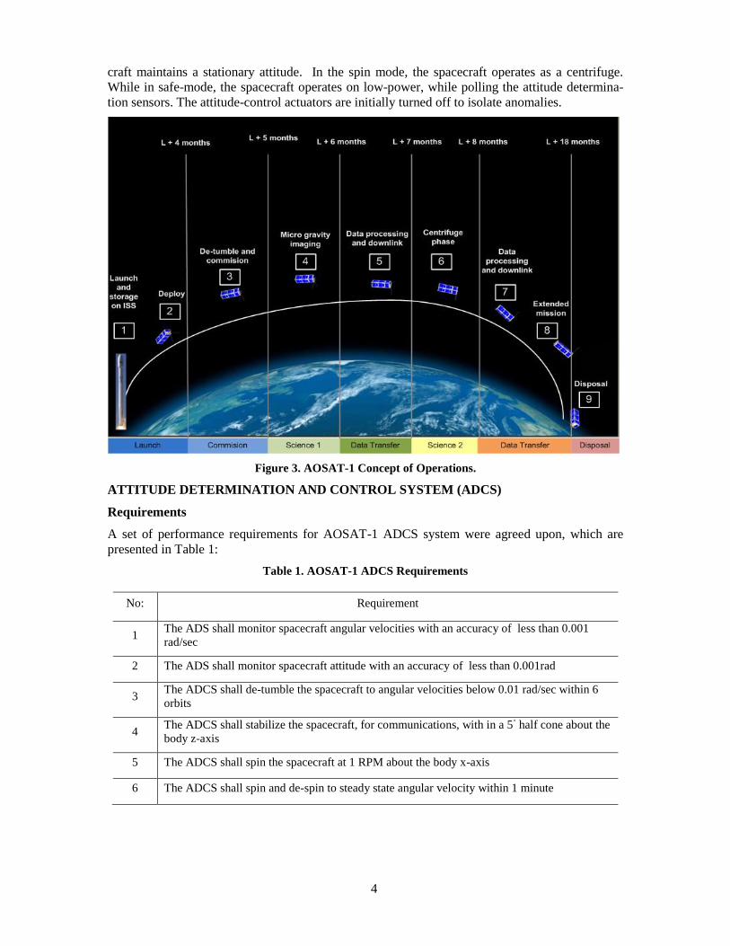
datory 20 minutes of unpowered flight. The concept of operations of AOSAT-1 is summarized in
Figure 3.The spacecraft is expected to tumble due deployment disturbances. Once the spacecraft
is powered, it will proceed with a de-tumbling sequence, followed by first contact with ground
control. Following first contact, the spacecraft will undergo a commissioning phase for about 1
month followed by Science-1 phase.
After the commissioning phase, the regolith stowed in the chamber is released into the payload
chamber and monitored under microgravity using a suite of cameras. Following the extended
microgravity experiments, AOSAT-1 will operate in a centrifuge mode, during Science-2 phase.
The spacecraft spins at 1 RPM about the body axis for experiments lasting 1-3 hours. The rego-
lith dynamics will be monitored using the onboard cameras. After each experiment, critical data
will be communicated back to ground using a UHF link to the ASU ground station.
Having outlined the major phases of the mission, the Attitude Control System (ACS), will
have the following 5 modes: De-tumble, nominal mode, spin mode, de-spin mode, and a safe
mode. De-tumble is executed upon power-up, post deployment. In the nominal mode, the space-
4
craft maintains a stationary attitude. In the spin mode, the spacecraft operates as a centrifuge.
While in safe-mode, the spacecraft operates on low-power, while polling the attitude determina-
tion sensors. The attitude-control actuators are initially turned off to isolate anomalies.
Figure 3. AOSAT-1 Concept of Operations.
ATTITUDE DETERMINATION AND CONTROL SYSTEM (ADCS)
Requirements
A set of performance requirements for AOSAT-1 ADCS system were agreed upon, which are
presented in Table 1:
Table 1. AOSAT-1 ADCS Requirements
No: Requirement
1 The ADS shall monitor spacecraft angular velocities with an accuracy of less than 0.001
rad/sec
2 The ADS shall monitor spacecraft attitude with an accuracy of less than 0.001rad
3 The ADCS shall de-tumble the spacecraft to angular velocities below 0.01 rad/sec within 6
orbits
4 The ADCS shall stabilize the spacecraft, for communications, with in a 5
◦ half cone about the
body z-axis
5 The ADCS shall spin the spacecraft at 1 RPM about the body x-axis
6 The ADCS shall spin and de-spin to steady state angular velocity within 1 minute
5
Requirements 1 and 2, are the ADS (Attitude Determination System) requirements, and will not
be discussed here. Requirements 3-6 are the ACS (Attitude Control System) requirements em-
ployed during different phases of operation.
Subsystem Components
The AOSAT-1 chassis is composed of TYVAK’s Intrepid platform [9]. This platform con-
sists of an Inertial Measurement Unit (IMU), sun sensor, and 3-axis magnetometers and 3-axis
magnetorquer coils. In addition, a Blue Canyon micro-reaction wheel is included on the space-
craft to enable higher torques and smooth rotations about the x-axis. Therefore, the total available
control input ( τ c) is
+ (1)
Where τ m denotes the control-torque generated by the magneto-torquer, and τ rw denotes the
control-torque generated by the single reaction wheel along x-axis.
Attitude Dynamics
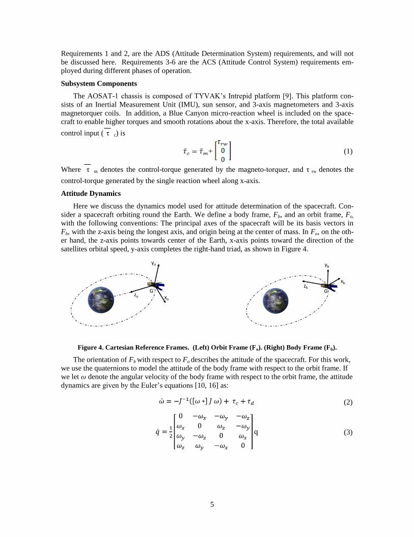
Here we discuss the dynamics model used for attitude determination of the spacecraft. Con-
sider a spacecraft orbiting round the Earth. We define a body frame, Fb, and an orbit frame, Fo,
with the following conventions: The principal axes of the spacecraft will be its basis vectors in
Fb, with the z-axis being the longest axis, and origin being at the center of mass. In Fo, on the oth-
er hand, the z-axis points towards center of the Earth, x-axis points toward the direction of the
satellites orbital speed, y-axis completes the right-hand triad, as shown in Figure 4.
Figure 4. Cartesian Reference Frames. (Left) Orbit Frame (Fo). (Right) Body Frame (Fb).
The orientation of Fb with respect to Fo describes the attitude of the spacecraft. For this work,
we use the quaternions to model the attitude of the body frame with respect to the orbit frame. If
we let ω denote the angular velocity of the body frame with respect to the orbit frame, the attitude
dynamics are given by the Euler’s equations [10, 16] as:
(2)
(3)
6
Here, τ c denotes the control torque as given by equation 2, and τ d denotes the net disturbance
torque. Equations 2 and 3 represent the attitude control model for a spacecraft in 3 dimensions.
Nominal model
If we choose J to be a constant matrix, and set τd =0, then equations 2 and 3 represents the nomi-
nal attitude control model.
Robust modelling
On the contrary if J can vary, and τd≠0 then equations 2 and 3 represents the attitude control
model for a more robust system. Modelling J and τd are discussed as follows:
Inertia Uncertainty
Strictly speaking for any real system, J cannot be known with perfect accuracy, even if the
object studied is rigid and with no moving parts. In such situations, we experimentally determine
a nominal value of J from experiments, and augment an uncertainty given by the standard devia-
tion of these experiments. However, AOSAT 1, has moving regolith inside it, which constantly
changes the moment of inertia compared a simpler rigid body spacecraft. Therefore, we charac-
terize the moment of inertia in a differently using a point mass model.
In this method, various components inside the spacecraft were listed along with their masses
mi, and centers of mass inside the body ri. The weighted average of the center of masses of all the
components gives the CG of the combined spacecraft.
(4)
With rg known, the body frame can now be defined with origin translated to rg., i.e.,
(5)
Here r’i denotes the position vector of the ith component in the body frame. Then by defining
ω= [ ω1 ω2 ω3] T
as a symbolic variable, the angular momentum vector H= [ H1 H2 H3] T
of the
spacecraft while exhibiting pure rotation is given by:
(6)
The moment of inertia tensor directly falls out as the co-efficients of ω, given by:
(7)
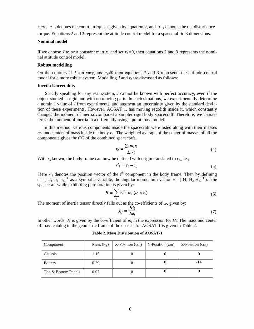
In other words, Jij is given by the co-efficient of ωj in the expression for Hi. The mass and center
of mass catalog in the geometric frame of the chassis for AOSAT 1 is given in Table 2.
Table 2. Mass Distribution of AOSAT-1
Component Mass (kg) X-Position (cm) Y-Position (cm) Z-Position (cm)
Chassis 1.15 0 0 0
Battery 0.29 0 0 -14
Top & Bottom Panels 0.07 0 0 0
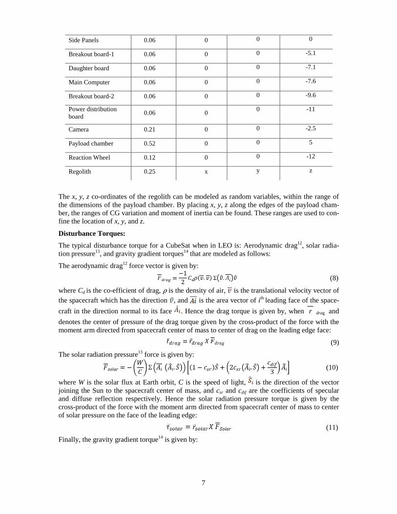
7
Side Panels 0.06 0 0 0
Breakout board-1 0.06 0 0 -5.1
Daughter board 0.06 0 0 -7.1
Main Computer 0.06 0 0 -7.6
Breakout board-2 0.06 0 0 -9.6
Power distribution
board 0.06 0
0 -11
Camera 0.21 0 0 -2.5
Payload chamber 0.52 0 0 5
Reaction Wheel 0.12 0 0 -12
Regolith 0.25 x y z
The x, y, z co-ordinates of the regolith can be modeled as random variables, within the range of
the dimensions of the payload chamber. By placing x, y, z along the edges of the payload cham-
ber, the ranges of CG variation and moment of inertia can be found. These ranges are used to con-
fine the location of x, y, and z.
Disturbance Torques:
The typical disturbance torque for a CubeSat when in LEO is: Aerodynamic drag12
, solar radia-
tion pressure13
, and gravity gradient torques14
that are modeled as follows:
The aerodynamic drag12
force vector is given by:
(8)
where Cd is the co-efficient of drag, ρ is the density of air, is the translational velocity vector of
the spacecraft which has the direction , and is the area vector of ith
leading face of the space-
craft in the direction normal to its face . Hence the drag torque is given by, when r drag and
denotes the center of pressure of the drag torque given by the cross-product of the force with the
moment arm directed from spacecraft center of mass to center of drag on the leading edge face:
(9)
The solar radiation pressure13
force is given by:
(10)
where W is the solar flux at Earth orbit, C is the speed of light, is the direction of the vector
joining the Sun to the spacecraft center of mass, and csr and cdif are the coefficients of specular
and diffuse reflection respectively. Hence the solar radiation pressure torque is given by the
cross-product of the force with the moment arm directed from spacecraft center of mass to center
of solar pressure on the face of the leading edge:
(11)
Finally, the gravity gradient torque14
is given by:
8
(12)
where, r b is the position vector joining center of earth to the center of mass of the spacecraft.
Therefore, the total disturbance torque can now be written as:
+ (13)
SIMULATIONS AND RESULTS
Simulations were developed in MATLAB and applied to the 4 functional control modes. The re-
sults of the simulation are presented below.
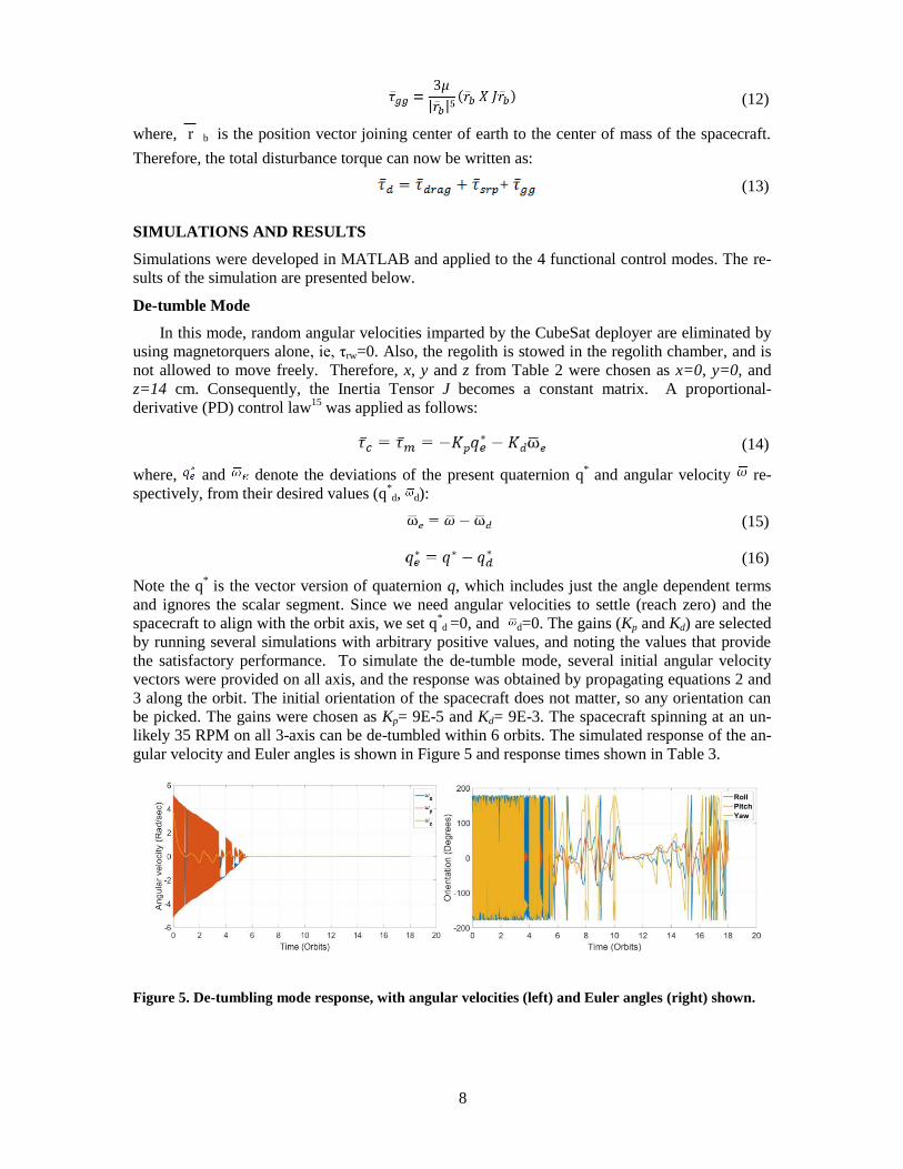
De-tumble Mode
In this mode, random angular velocities imparted by the CubeSat deployer are eliminated by
using magnetorquers alone, ie, τrw=0. Also, the regolith is stowed in the regolith chamber, and is
not allowed to move freely. Therefore, x, y and z from Table 2 were chosen as x=0, y=0, and
z=14 cm. Consequently, the Inertia Tensor J becomes a constant matrix. A proportional-
derivative (PD) control law15
was applied as follows:
(14)
where, and denote the deviations of the present quaternion q* and angular velocity re-
spectively, from their desired values (q*d, d):
(15)
(16)
Note the q* is the vector version of quaternion q, which includes just the angle dependent terms
and ignores the scalar segment. Since we need angular velocities to settle (reach zero) and the
spacecraft to align with the orbit axis, we set q*d =0, and d=0. The gains (Kp and Kd) are selected
by running several simulations with arbitrary positive values, and noting the values that provide
the satisfactory performance. To simulate the de-tumble mode, several initial angular velocity
vectors were provided on all axis, and the response was obtained by propagating equations 2 and
3 along the orbit. The initial orientation of the spacecraft does not matter, so any orientation can
be picked. The gains were chosen as Kp= 9E-5 and Kd= 9E-3. The spacecraft spinning at an un-
likely 35 RPM on all 3-axis can be de-tumbled within 6 orbits. The simulated response of the an-
gular velocity and Euler angles is shown in Figure 5 and response times shown in Table 3.
Figure 5. De-tumbling mode response, with angular velocities (left) and Euler angles (right) shown.
9
Note that the body frame does not have to align with the response frame here, since the de-tumble
logic places more emphasis on reducing the angular velocity errors than the quaternion errors.
Table 3. De-tumbling Time
Initial Angular Velocity De-tumbling time (Orbits)
30 5.32
35 5.77
40 6.05
45 6.43
50 6.93
55 7.10
60 7.60
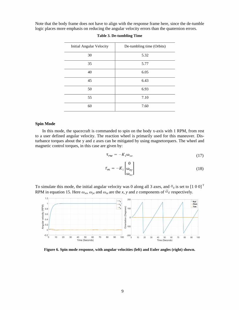
Spin Mode
In this mode, the spacecraft is commanded to spin on the body x-axis with 1 RPM, from rest
to a user defined angular velocity. The reaction wheel is primarily used for this maneuver. Dis-
turbance torques about the y and z axes can be mitigated by using magnetorquers. The wheel and
magnetic control torques, in this case are given by:
(17)
(18)
To simulate this mode, the initial angular velocity was 0 along all 3 axes, and d is set to [1 0 0] T
RPM in equation 15. Here ωxe, ωye and ωze are the x, y and z components of respectively.
Figure 6. Spin mode response, with angular velocities (left) and Euler angles (right) shown.
10
Gains for this mode we chosen as K1=7E-3 and K2=7E-4. As seen in Figure 6, the spacecraft can
achieved a desired, constant angular velocity in less than 10 seconds.
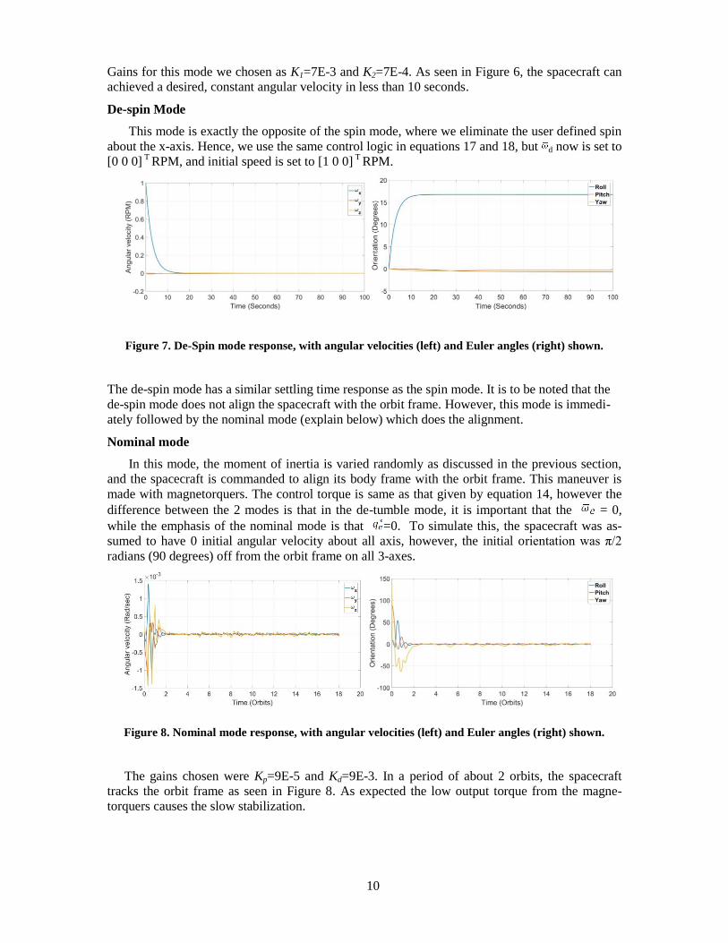
De-spin Mode
This mode is exactly the opposite of the spin mode, where we eliminate the user defined spin
about the x-axis. Hence, we use the same control logic in equations 17 and 18, but d now is set to
[0 0 0] T
RPM, and initial speed is set to [1 0 0] T
RPM.
Figure 7. De-Spin mode response, with angular velocities (left) and Euler angles (right) shown.
The de-spin mode has a similar settling time response as the spin mode. It is to be noted that the
de-spin mode does not align the spacecraft with the orbit frame. However, this mode is immedi-
ately followed by the nominal mode (explain below) which does the alignment.
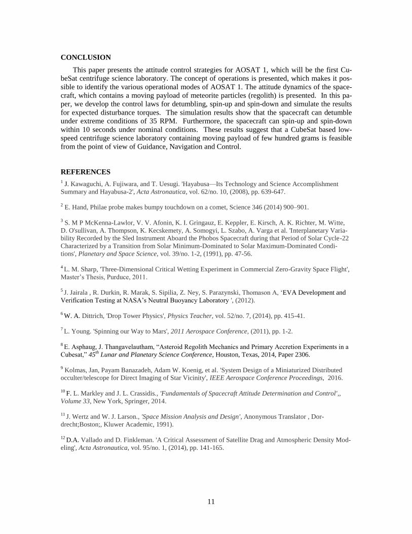
Nominal mode
In this mode, the moment of inertia is varied randomly as discussed in the previous section,
and the spacecraft is commanded to align its body frame with the orbit frame. This maneuver is
made with magnetorquers. The control torque is same as that given by equation 14, however the
difference between the 2 modes is that in the de-tumble mode, it is important that the = 0,
while the emphasis of the nominal mode is that =0. To simulate this, the spacecraft was as-
sumed to have 0 initial angular velocity about all axis, however, the initial orientation was π/2
radians (90 degrees) off from the orbit frame on all 3-axes.
Figure 8. Nominal mode response, with angular velocities (left) and Euler angles (right) shown.
The gains chosen were Kp=9E-5 and Kd=9E-3. In a period of about 2 orbits, the spacecraft
tracks the orbit frame as seen in Figure 8. As expected the low output torque from the magne-
torquers causes the slow stabilization.
11
CONCLUSION
This paper presents the attitude control strategies for AOSAT 1, which will be the first Cu-
beSat centrifuge science laboratory. The concept of operations is presented, which makes it pos-
sible to identify the various operational modes of AOSAT 1. The attitude dynamics of the space-
craft, which contains a moving payload of meteorite particles (regolith) is presented. In this pa-
per, we develop the control laws for detumbling, spin-up and spin-down and simulate the results
for expected disturbance torques. The simulation results show that the spacecraft can detumble
under extreme conditions of 35 RPM. Furthermore, the spacecraft can spin-up and spin-down
within 10 seconds under nominal conditions. These results suggest that a CubeSat based low-
speed centrifuge science laboratory containing moving payload of few hundred grams is feasible
from the point of view of Guidance, Navigation and Control.
REFERENCES
1 J. Kawaguchi, A. Fujiwara, and T. Uesugi. 'Hayabusa—Its Technology and Science Accomplishment
Summary and Hayabusa-2', Acta Astronautica, vol. 62/no. 10, (2008), pp. 639-647.
2 E. Hand, Philae probe makes bumpy touchdown on a comet, Science 346 (2014) 900–901.
3 S. M P McKenna-Lawlor, V. V. Afonin, K. I. Gringauz, E. Keppler, E. Kirsch, A. K. Richter, M. Witte,
D. O'sullivan, A. Thompson, K. Kecskemety, A. Somogyi, L. Szabo, A. Varga et al. 'Interplanetary Varia-
bility Recorded by the Sled Instrument Aboard the Phobos Spacecraft during that Period of Solar Cycle-22
Characterized by a Transition from Solar Minimum-Dominated to Solar Maximum-Dominated Condi-
tions', Planetary and Space Science, vol. 39/no. 1-2, (1991), pp. 47-56.
4 L. M. Sharp, 'Three-Dimensional Critical Wetting Experiment in Commercial Zero-Gravity Space Flight',
Master’s Thesis, Purduce, 2011.
5 J. Jairala , R. Durkin, R. Marak, S. Sipilia, Z. Ney, S. Parazynski, Thomason A, ‘EVA Development and
Verification Testing at NASA’s Neutral Buoyancy Laboratory ', (2012).
6 W. A. Dittrich, 'Drop Tower Physics', Physics Teacher, vol. 52/no. 7, (2014), pp. 415-41.
7 L. Young. 'Spinning our Way to Mars', 2011 Aerospace Conference, (2011), pp. 1-2.
8 E. Asphaug, J. Thangavelautham, “Asteroid Regolith Mechanics and Primary Accretion Experiments in a
Cubesat,” 45th
Lunar and Planetary Science Conference, Houston, Texas, 2014, Paper 2306.
9 Kolmas, Jan, Payam Banazadeh, Adam W. Koenig, et al. 'System Design of a Miniaturized Distributed
occulter/telescope for Direct Imaging of Star Vicinity', IEEE Aerospace Conference Proceedings, 2016.
10
F. L. Markley and J. L. Crassidis., 'Fundamentals of Spacecraft Attitude Determination and Control',,
Volume 33, New York, Springer, 2014.
11
J. Wertz and W. J. Larson., 'Space Mission Analysis and Design', Anonymous Translator , Dor-
drecht;Boston;, Kluwer Academic, 1991).
12
D.A. Vallado and D. Finkleman. 'A Critical Assessment of Satellite Drag and Atmospheric Density Mod-
eling', Acta Astronautica, vol. 95/no. 1, (2014), pp. 141-165.
12
13 M. List, S. Bremer, B. Rievers, et al. 'Modelling of Solar Radiation Pressure Effects: Parameter Analysis
for the MICROSCOPE Mission', International Journal of Aerospace Engineering, vol. 2015/ (2015), pp. 1-
14.
14
Y. Wang and S. Xu. 'Attitude Stability of a Spacecraft on a Stationary Orbit Around an Asteroid Sub-
jected to Gravity Gradient Torque', Celestial Mechanics and Dynamical Astronomy, vol. 115, 2013, pp.
333-352.
15
D. Torczynski, A. Rouzbeh, and P. Massioni. 'Magnetorquer Based Attitude Control for a Nanosatellite
Testplatform', AIAA Infotech at Aerospace, 2010.
16
J. Diebel, "Representing attitude: Euler angles, unit quaternions, and rotation vectors." Matrix 58.15-16
(2006): 1-35.
17
J. Thangavelautham, A. Thoesen, F. Gadau, G. Hutchins, E. Asphaug, I. Alizadeh, “Low-Cost Science
Laboratory in Microgravity Using a CubeSat Centrifuge Framework,” Proceedings of the 65th Internation-
al Astronautical Congress, Toronto, Canada, 2014.
18
J. Lightholder, A. Thoesen, E. Adamson, J. Jakubowski, R. Nallapu, S. Smallwood, L. Raura, A. Klesh,
E. Asphaug, J. Thangavelautham, “Asteroid Origins Satellite (AOSAT) I: An On-orbit Centrifuge Science
Laboratory,” Acta Astronautica, Vol 133, 2017, pp. 81-94.