Embed Size (px)
Citation preview
Altivar 610
EAV64381 12/2014
EA
V64
381.
01
www.schneider-electric.com
Altivar 610Variable Speed Drives
Installation Manual
12/2014

The information provided in this documentation contains general descriptions and/or technical character-istics of the performance of the products contained herein. This documentation is not intended as a substitute for and is not to be used for determining suitability or reliability of these products for specific user applications. It is the duty of any such user or integrator to perform the appropriate and complete risk analysis, evaluation and testing of the products with respect to the relevant specific application or use thereof. Neither Schneider Electric nor any of its affiliates or subsidiaries shall be responsible or liable for misuse of the information contained herein. If you have any suggestions for improvements or amendments or have found errors in this publication, please notify us.
No part of this document may be reproduced in any form or by any means, electronic or mechanical, including photocopying, without express written permission of Schneider Electric.
All pertinent state, regional, and local safety regulations must be observed when installing and using this product. For reasons of safety and to help ensure compliance with documented system data, only the manufacturer should perform repairs to components.
When devices are used for applications with technical safety requirements, the relevant instructions must be followed.
Failure to use Schneider Electric software or approved software with our hardware products may result in injury, harm, or improper operating results.
Failure to observe this information can result in injury or equipment damage.
© 2014 Schneider Electric. All rights reserved.
2 EAV64381 12/2014
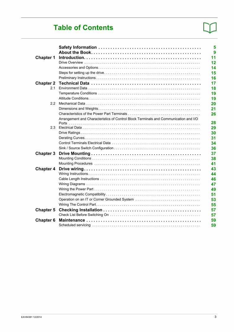
Table of Contents
Safety Information . . . . . . . . . . . . . . . . . . . . . . . . . . . . . . . . . . . . . . . . . . . 5About the Book. . . . . . . . . . . . . . . . . . . . . . . . . . . . . . . . . . . . . . . . . . . . . . 9
Chapter 1 Introduction. . . . . . . . . . . . . . . . . . . . . . . . . . . . . . . . . . . . . . . . . . . . . . . . . 11Drive Overview . . . . . . . . . . . . . . . . . . . . . . . . . . . . . . . . . . . . . . . . . . . . . . . . . . . . . . . . . . . 12Accessories and Options. . . . . . . . . . . . . . . . . . . . . . . . . . . . . . . . . . . . . . . . . . . . . . . . . . . . 14Steps for setting up the drive. . . . . . . . . . . . . . . . . . . . . . . . . . . . . . . . . . . . . . . . . . . . . . . . . 15Preliminary Instructions . . . . . . . . . . . . . . . . . . . . . . . . . . . . . . . . . . . . . . . . . . . . . . . . . . . . . 16
Chapter 2 Technical Data . . . . . . . . . . . . . . . . . . . . . . . . . . . . . . . . . . . . . . . . . . . . . . 172.1 Environment Data . . . . . . . . . . . . . . . . . . . . . . . . . . . . . . . . . . . . . . . . . . . . . . . . . . . . . . . . . 18
Temperature Conditions . . . . . . . . . . . . . . . . . . . . . . . . . . . . . . . . . . . . . . . . . . . . . . . . . . . . 19Altitude Conditions. . . . . . . . . . . . . . . . . . . . . . . . . . . . . . . . . . . . . . . . . . . . . . . . . . . . . . . . . 19
2.2 Mechanical Data . . . . . . . . . . . . . . . . . . . . . . . . . . . . . . . . . . . . . . . . . . . . . . . . . . . . . . . . . . 20Dimensions and Weights. . . . . . . . . . . . . . . . . . . . . . . . . . . . . . . . . . . . . . . . . . . . . . . . . . . . 21Characteristics of the Power Part Terminals . . . . . . . . . . . . . . . . . . . . . . . . . . . . . . . . . . . . . 26Arrangement and Characteristics of Control Block Terminals and Communication and I/O Ports . . . . . . . . . . . . . . . . . . . . . . . . . . . . . . . . . . . . . . . . . . . . . . . . . . . . . . . . . . . . . . . . . . . 28
2.3 Electrical Data . . . . . . . . . . . . . . . . . . . . . . . . . . . . . . . . . . . . . . . . . . . . . . . . . . . . . . . . . . . . 29Drive Ratings . . . . . . . . . . . . . . . . . . . . . . . . . . . . . . . . . . . . . . . . . . . . . . . . . . . . . . . . . . . . . 30Derating Curves. . . . . . . . . . . . . . . . . . . . . . . . . . . . . . . . . . . . . . . . . . . . . . . . . . . . . . . . . . . 31Control Terminals Electrical Data . . . . . . . . . . . . . . . . . . . . . . . . . . . . . . . . . . . . . . . . . . . . . 34Sink / Source Switch Configuration . . . . . . . . . . . . . . . . . . . . . . . . . . . . . . . . . . . . . . . . . . . . 36
Chapter 3 Drive Mounting . . . . . . . . . . . . . . . . . . . . . . . . . . . . . . . . . . . . . . . . . . . . . . 37Mounting Conditions . . . . . . . . . . . . . . . . . . . . . . . . . . . . . . . . . . . . . . . . . . . . . . . . . . . . . . . 38Mounting Procedures . . . . . . . . . . . . . . . . . . . . . . . . . . . . . . . . . . . . . . . . . . . . . . . . . . . . . . 41
Chapter 4 Drive wiring . . . . . . . . . . . . . . . . . . . . . . . . . . . . . . . . . . . . . . . . . . . . . . . . . 43Wiring Instructions . . . . . . . . . . . . . . . . . . . . . . . . . . . . . . . . . . . . . . . . . . . . . . . . . . . . . . . . . 44Cable Length Instructions . . . . . . . . . . . . . . . . . . . . . . . . . . . . . . . . . . . . . . . . . . . . . . . . . . . 46Wiring Diagrams . . . . . . . . . . . . . . . . . . . . . . . . . . . . . . . . . . . . . . . . . . . . . . . . . . . . . . . . . . 47Wiring the Power Part . . . . . . . . . . . . . . . . . . . . . . . . . . . . . . . . . . . . . . . . . . . . . . . . . . . . . . 49Electromagnetic Compatibility . . . . . . . . . . . . . . . . . . . . . . . . . . . . . . . . . . . . . . . . . . . . . . . . 51Operation on an IT or Corner Grounded System . . . . . . . . . . . . . . . . . . . . . . . . . . . . . . . . . 53Wiring The Control Part . . . . . . . . . . . . . . . . . . . . . . . . . . . . . . . . . . . . . . . . . . . . . . . . . . . . . 55
Chapter 5 Checking Installation . . . . . . . . . . . . . . . . . . . . . . . . . . . . . . . . . . . . . . . . . 57Check List Before Switching On . . . . . . . . . . . . . . . . . . . . . . . . . . . . . . . . . . . . . . . . . . . . . . 57
Chapter 6 Maintenance . . . . . . . . . . . . . . . . . . . . . . . . . . . . . . . . . . . . . . . . . . . . . . . . 59Scheduled servicing . . . . . . . . . . . . . . . . . . . . . . . . . . . . . . . . . . . . . . . . . . . . . . . . . . . . . . . 59
EAV64381 12/2014 3

4 EAV64381 12/2014
Safety Information
Important Information
NOTICERead these instructions carefully, and look at the equipment to become familiar with the device before trying to install, operate, or maintain it. The following special messages may appear throughout this documentation or on the equipment to warn of potential hazards or to call attention to information that clarifies or simplifies a procedure.
PLEASE NOTEElectrical equipment should be installed, operated, serviced, and maintained only by qualified personnel. No responsibility is assumed by Schneider Electric for any consequences arising out of the use of this material.
A qualified person is one who has skills and knowledge related to the construction and operation of electrical equipment and its installation, and has received safety training to recognize and avoid the hazards involved.
Qualification Of PersonnelOnly appropriately trained persons who are familiar with and understand the contents of this manual and all other pertinent product documentation are authorized to work on and with this product. In addition, these persons must have received safety training to recognize and avoid hazards involved. These persons must have sufficient technical training, knowledge and experience and be able to foresee and detect potential hazards that may be caused by using the product, by changing the settings and by the mechanical, electrical and electronic equipment of the entire system in which the product is used. All persons working on and with the product must be fully familiar with all applicable standards, directives, and accident prevention regulations when performing such work.
EAV64381 12/2014 5
Intended UseThis product is a drive for three-phase synchronous and asynchronous motors and intended for industrial use according to this manual.The product may only be used in compliance with all applicable safety regulations and directives, the specified requirements and the technical data.Prior to using the product, you must perform a risk assessment in view of the planned application. Based on the results, the appropriate safety measures must be implemented.Since the product is used as a component in an entire system, you must ensure the safety of persons by means of the design of this entire system (for example, machine design). Any use other than the use explicitly permitted is prohibited and can result in hazards. Electrical equipment should be installed, operated, serviced, and maintained only by qualified personnel.
Product Related InformationRead and understand these instructions before performing any procedure with this drive.
DANGERHAZARD OF ELECTRIC SHOCK, EXPLOSION OR ARC FLASH
Only appropriately trained persons who are familiar with and understand the contents of this manual and all other pertinent product documentation and who have received safety training to recognize and avoid hazards involved are authorized to work on and with this drive system. Installation, adjustment, repair and maintenance must be performed by qualified personnel.The system integrator is responsible for compliance with all local and national electrical code requirements as well as all other applicable regulations with respect to grounding of all equipment.Many components of the product, including the printed circuit boards, operate with mains voltage. Do not touch. Use only electrically insulated tools.Do not touch unshielded components or terminals with voltage present.Motors can generate voltage when the shaft is rotated. Prior to performing any type of work on the drive system, block the motor shaft to prevent rotation.AC voltage can couple voltage to unused conductors in the motor cable. Insulate both ends of unused conductors of the motor cable.Do not short across the DC bus terminals or the DC bus capacitors or the braking resistor terminals.Before performing work on the drive system:
Disconnect all power, including external control power that may be present.Place a Do Not Turn On label on all power switches.Lock all power switches in the open position. Wait 15 minutes to allow the DC bus capacitors to discharge. The DC bus LED is not an indicator of the absence of DC bus voltage that can exceed 800 Vdc.Measure the voltage on the DC bus between the DC bus terminals (PA/+, PC/-) using a properly rated voltmeter to verify that the voltage is <42 VdcIf the DC bus capacitors do not discharge properly, contact your local Schneider Electric represen-tative. Do not repair or operate the product.
Install and close all covers before applying voltage.
Failure to follow these instructions will result in death or serious injury.
WARNINGUNEXPECTED MOVEMENTDrive systems may perform unexpected movements because of incorrect wiring, incorrect settings, incorrect data or other errors.
Carefully install the wiring in accordance with the EMC requirements.Do not operate the product with unknown or unsuitable settings or data.Perform a comprehensive commissioning test.
Failure to follow these instructions can result in death, serious injury, or equipment damage.
6 EAV64381 12/2014
Damaged products or accessories may cause electric shock or unanticipated equipment operation.
Contact your local Schneider Electric sales office if you detect any damage whatsoever.
(1) For USA: Additional information, refer to NEMA ICS 1.1 (latest edition), Safety Guidelines for the Application, Installation, and Maintenance of Solid State Control and to NEMA ICS 7.1 (latest edition), Safety Standards for Construction and Guide for Selection, Installation and Operation of Adjustable-Speed Drive Systems.
DANGERELECTRIC SHOCK OR UNANTICIPATED EQUIPMENT OPERATIONDo not use damaged products or accessories.
Failure to follow these instructions will result in death or serious injury.
WARNINGLOSS OF CONTROL
The designer of any control scheme must consider the potential failure modes of control paths and, for critical control functions, provide a means to achieve a safe state during and after a path failure. Examples of critical control functions are emergency stop, overtravel stop, power outage and restart.Separate or redundant control paths must be provided for critical control functions.System control paths may include communication links. Consideration must be given to the implications of unanticipated transmission delays or failures of the link.Observe all accident prevention regulations and local safety guidelines (1).Each implementation of the product must be individually and thoroughly tested for proper operation before being placed into service.
Failure to follow these instructions can result in death, serious injury, or equipment damage.
NOTICEDESTRUCTION DUE TO INCORRECT MAINS VOLTAGEBefore switching on and configuring the product, verify that it is approved for the mains voltage
Failure to follow these instructions can result in equipment damage.
WARNINGHOT SURFACES
Ensure that any contact with hot surfaces is avoided.Do not allow flammable or heat-sensitive parts in the immediate vicinity of hot surfaces.Verify that the heat dissipation is sufficient by performing a test run under maximum load conditions.
Failure to follow these instructions can result in death, serious injury, or equipment damage.
EAV64381 12/2014 7

8 EAV64381 12/2014

About the Book
At a Glance
Document ScopeThe purpose of this document is:
to give you mechanical and electrical information related to the drive,to show you how to install and wire this drive.
Validity NoteNOTE: The products listed in the document are not all available at the time of publication of this document online. The data, illustrations and product specifications listed in the guide will be completed and updated as the product availabilities evolve. Updates to the guide will be available for download once products are released on the market.
This documentation is valid for the Altivar 610 drive.
The technical characteristics of the devices described in this document also appear online. To access this information online:
The characteristics that are presented in this manual should be the same as those characteristics that appear online. In line with our policy of constant improvement, we may revise content over time to improve clarity and accuracy. If you see a difference between the manual and online information, use the online information as your reference.
Related DocumentsUse your tablet or your PC to quickly access detailed and comprehensive information on all our products on www.schneider-electric.com
The internet site provides the information you need for products and solutionsThe whole catalog for detailed characteristics and selection guidesThe CAD files to help design your installation, available in over 20 different file formatsAll software and firmware to maintain your installation up to dateA large quantity of White Papers, Environment documents, Application solutions, Specifications... to gain a better understanding of our electrical systems and equipment or automationAnd finally all the User Guides related to your drive, listed below:
You can download these technical publications and other technical information from our website at www.schneider-electric.com.
Step Action
1 Go to the Schneider Electric home page www.schneider-electric.com.
2 In the Search box type the reference of a product or the name of a product range.Do not include blank spaces in the model number/product range.To get information on grouping similar modules, use asterisks (*).
3 If you entered a reference, go to the Product Datasheets search results and click on the reference that interests you.If you entered the name of a product range, go to the Product Ranges search results and click on the product range that interests you.
4 If more than one reference appears in the Products search results, click on the reference that interests you.
5 Depending on the size of your screen, you may need to scroll down to see the data sheet.
6 To save or print a data sheet as a .pdf file, click Download XXX product datasheet.
Title of Documentation Reference NumberAltivar 610 Quick Start EAV64374 (English), EAV64379 (Chinese)Altivar 610 Installation Manual EAV64381 (English), EAV64386 (Chinese)Altivar 610 Programming Manual EAV64387 (English), EAV64393 (Chinese)Altivar 610 Communication Parameters File EAV64394 (English)Altivar 610 Modbus Manual EAV64395 (English)Altivar 610 PROFIBUS DP manual EAV64396 (English)
EAV64381 12/2014 9

Standards and TerminologyThe technical terms, terminology, and the corresponding descriptions in this manual normally use the terms or definitions in the relevant standards.
In the area of drive systems this includes, but is not limited to, terms such as error, error message, failure, fault, fault reset, protection, safe state, safety function, warning, warning message, and so on.
Among others, these standards include:IEC 61800 series: Adjustable speed electrical power drive systemsIEC 61508 Ed.2 series: Functional safety of electrical/electronic/programmable electronic safety-relatedEN 954-1 Safety of machinery - Safety related parts of control systemsEN ISO 13849-1 & 2 Safety of machinery - Safety related parts of control systems.IEC 61158 series: Industrial communication networks - Fieldbus specificationsIEC 61784 series: Industrial communication networks - ProfilesIEC 60204-1: Safety of machinery - Electrical equipment of machines – Part 1: General requirements
10 EAV64381 12/2014

Altivar 610
EAV64381 12/2014
Introduction
Chapter 1Introduction
What Is in This Chapter?This chapter contains the following topics:
Topic Page
Drive Overview 12
Accessories and Options 14
Steps for setting up the drive 15
Preliminary Instructions 16
EAV64381 12/2014 11
Drive Overview
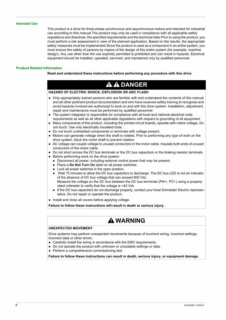
Frame SizesThe family of Altivar 610 includes 6 frame sizes for a wide range of applications and power requirements
Frame Size 1 Frame Size 2
3-phase 380...415 V, 0.75...7.5 kW, 1...10 HP 3-phase 380...415 V, 11 and 15 kW, 15 and 20 HP
ATV610U07N4...U75N4 ATV610D11N4 and D15N4
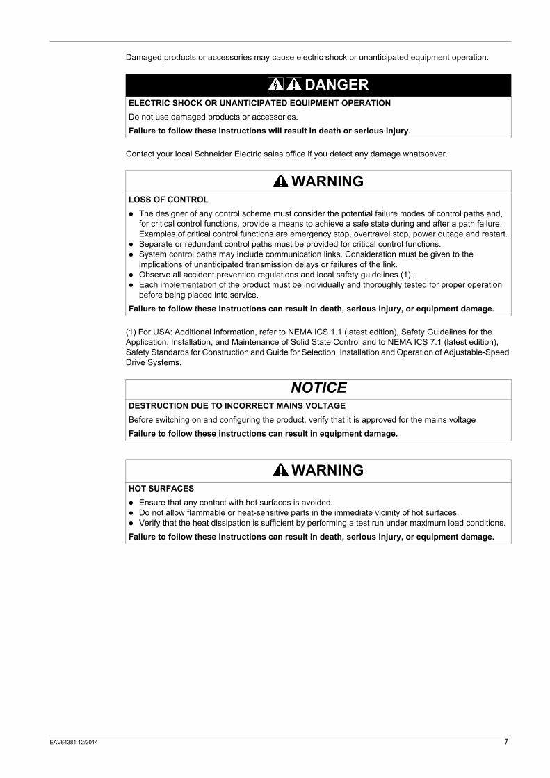
Frame Size 3 Frame Size 4
3-phase 380...415 V, 18.5 and 22 kW, 25 and 30 HP 3-phase 380...415 V, 30...45 kW, 40...60 HP
ATV610D18N4 and D22N4 ATV610D30N4...D45N4
12 EAV64381 12/2014
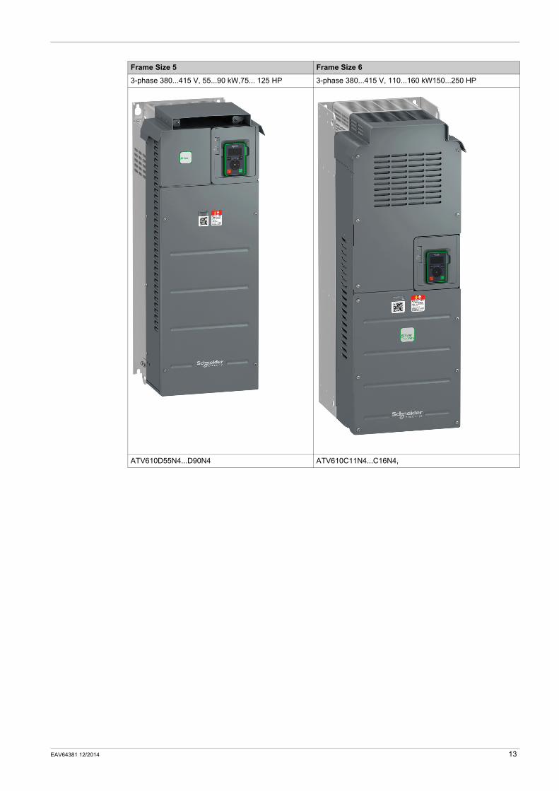
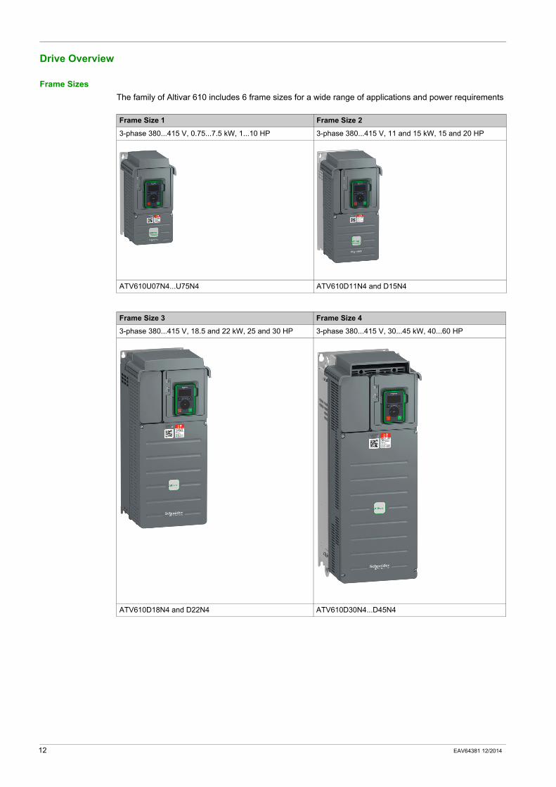
Frame Size 5 Frame Size 6
3-phase 380...415 V, 55...90 kW,75... 125 HP 3-phase 380...415 V, 110...160 kW150...250 HP
ATV610D55N4...D90N4 ATV610C11N4...C16N4,
EAV64381 12/2014 13
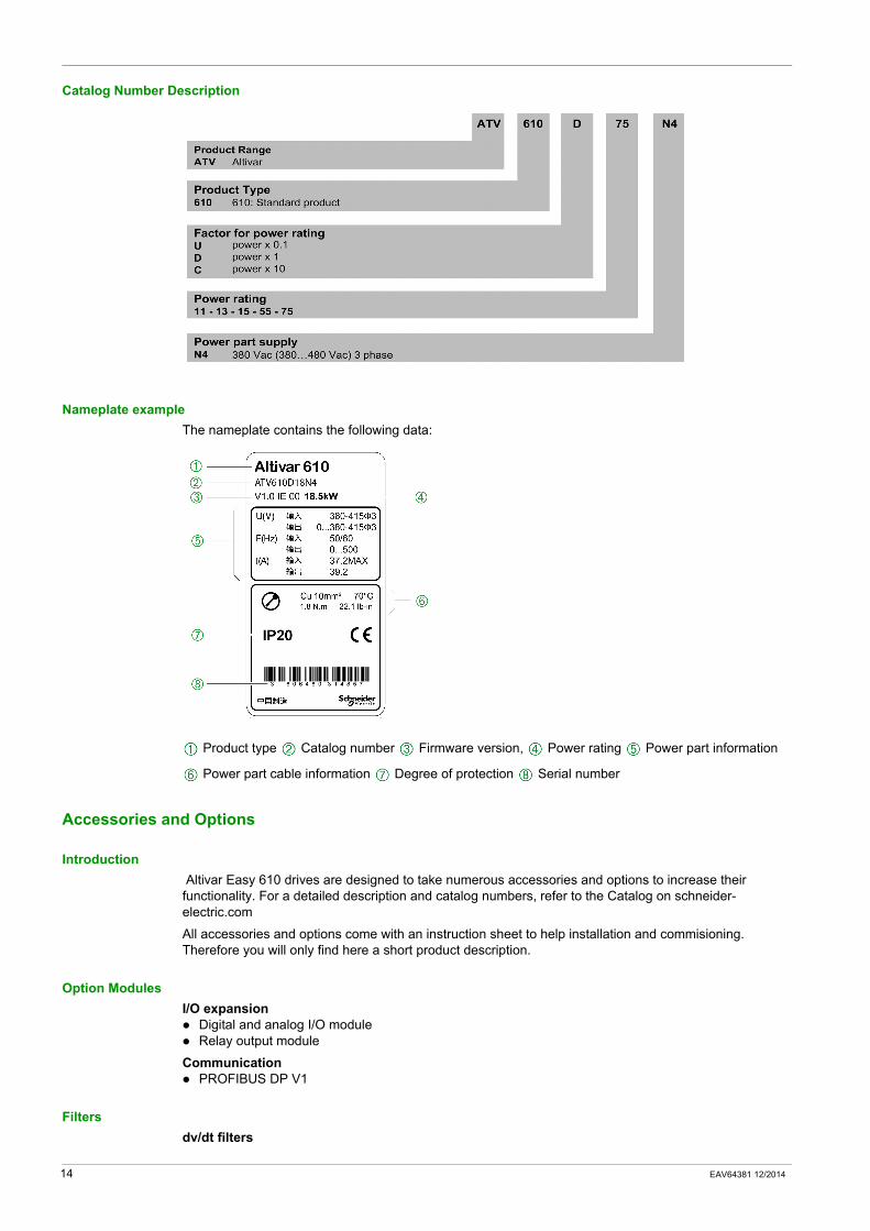
Catalog Number Description
Nameplate exampleThe nameplate contains the following data:
Product type Catalog number Firmware version, Power rating Power part information
Power part cable information Degree of protection Serial number
Accessories and Options
Introduction Altivar Easy 610 drives are designed to take numerous accessories and options to increase their functionality. For a detailed description and catalog numbers, refer to the Catalog on schneider-electric.com
All accessories and options come with an instruction sheet to help installation and commisioning. Therefore you will only find here a short product description.
Option ModulesI/O expansion
Digital and analog I/O moduleRelay output module
CommunicationPROFIBUS DP V1
Filtersdv/dt filters
14 EAV64381 12/2014
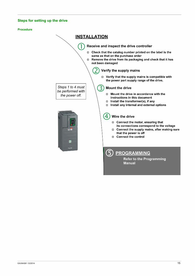
Steps for setting up the drive
Procedure
EAV64381 12/2014 15
Preliminary Instructions
Handling and Storage
To help protect the drive before installation, handle and store the device in its packaging. Ensure that the ambient conditions are acceptable.
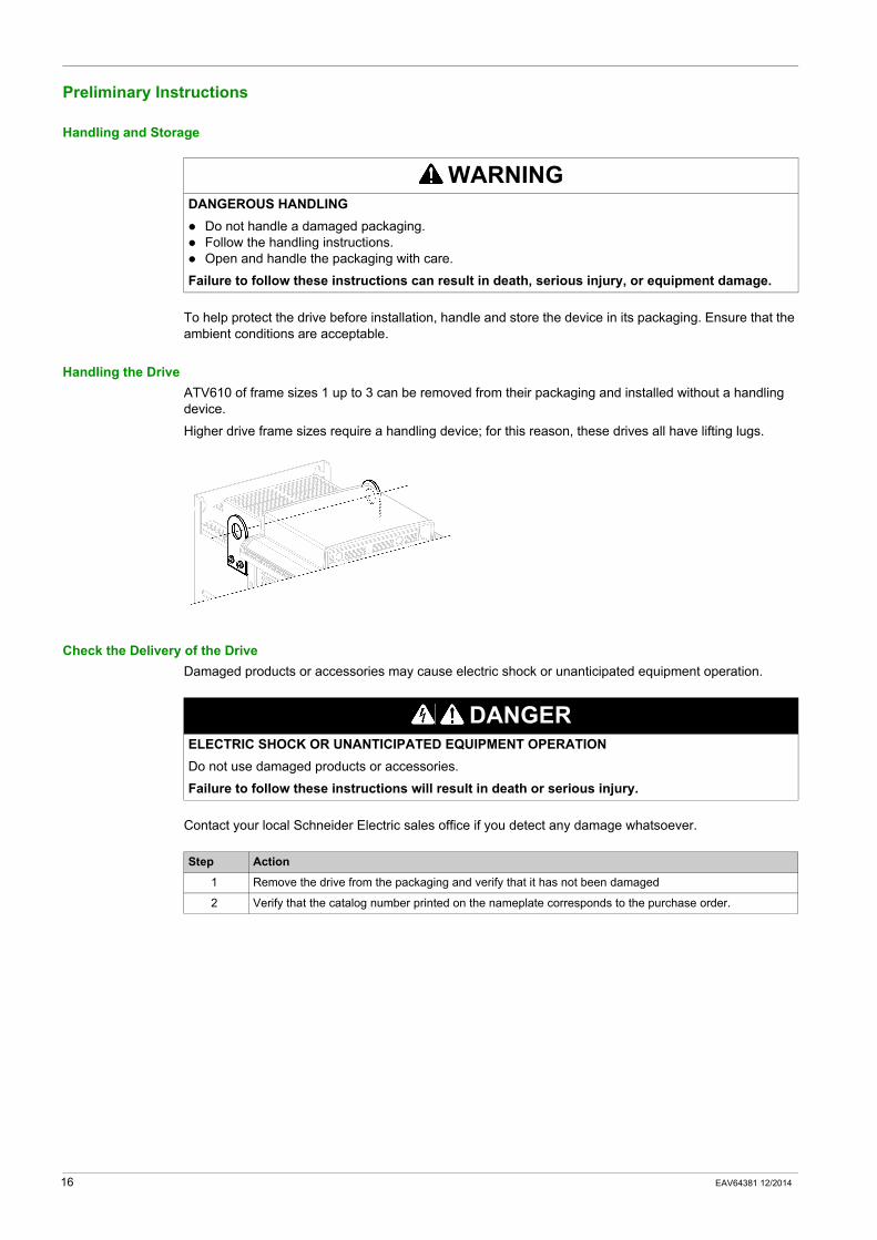
Handling the DriveATV610 of frame sizes 1 up to 3 can be removed from their packaging and installed without a handling device.
Higher drive frame sizes require a handling device; for this reason, these drives all have lifting lugs.
Check the Delivery of the DriveDamaged products or accessories may cause electric shock or unanticipated equipment operation.
Contact your local Schneider Electric sales office if you detect any damage whatsoever.
WARNINGDANGEROUS HANDLING
Do not handle a damaged packaging.Follow the handling instructions.Open and handle the packaging with care.
Failure to follow these instructions can result in death, serious injury, or equipment damage.
DANGERELECTRIC SHOCK OR UNANTICIPATED EQUIPMENT OPERATIONDo not use damaged products or accessories.
Failure to follow these instructions will result in death or serious injury.
Step Action
1 Remove the drive from the packaging and verify that it has not been damaged
2 Verify that the catalog number printed on the nameplate corresponds to the purchase order.
16 EAV64381 12/2014

Altivar 610
EAV64381 12/2014
Technical Data
Chapter 2Technical Data
What Is in This Chapter?This chapter contains the following sections:
Section Topic Page
2.1 Environment Data 18
2.2 Mechanical Data 20
2.3 Electrical Data 29
EAV64381 12/2014 17

Environment Data
Section 2.1Environment Data
What Is in This Section?This section contains the following topics:
Topic Page
Temperature Conditions 19
Altitude Conditions 19
18 EAV64381 12/2014
Temperature Conditions
Climatic Environmental Conditions for Transportation and StorageThe environment during transportation and storage must be dry and free from dust.
Climatic Environmental Conditions for OperationThe maximum permissible ambient temperature during operation depends on the mounting distances between the devices and on the required power. Observe the pertinent instructions in the chapter Drive Mounting (see page 37).
(1) Refer to Derating Curves section (see page 31).
Altitude Conditions
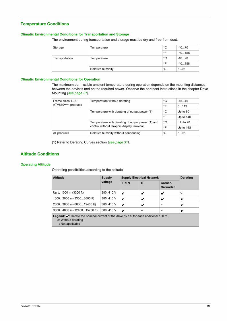
Operating AltitudeOperating possibilities according to the altitude
Storage Temperature °C -40...70
°F -40...158
Transportation Temperature °C -40...70
°F -40...158
Relative humidity % 5...95
Frame sizes 1...6 ATV610••••• products
Temperature without derating °C -15...45
°F 5...113
Temperature with derating of output power (1) °C Up to 60
°F Up to 140
Temperature with derating of output power (1) and control without Graphic display terminal
°C Up to 70
°F Up to 168
All products Relative humidity without condensing % 5...95
Altitude Supply voltage
Supply Electrical Network Derating
TT/TN IT Corner-Grounded
Up to 1000 m (3300 ft) 380..410 V o
1000...2000 m (3300...6600 ft) 380..410 V
2000...3800 m (6600...12400 ft) 380..410 V –
3800...4800 m (12400...15700 ft) 380..410 V – –
Legend: : Derate the nominal current of the drive by 1% for each additional 100 m.o: Without derating–: Not applicable
EAV64381 12/2014 19

Mechanical Data
Section 2.2Mechanical Data
What Is in This Section?This section contains the following topics:
Topic Page
Dimensions and Weights 21
Characteristics of the Power Part Terminals 26
Arrangement and Characteristics of Control Block Terminals and Communication and I/O Ports 28
20 EAV64381 12/2014
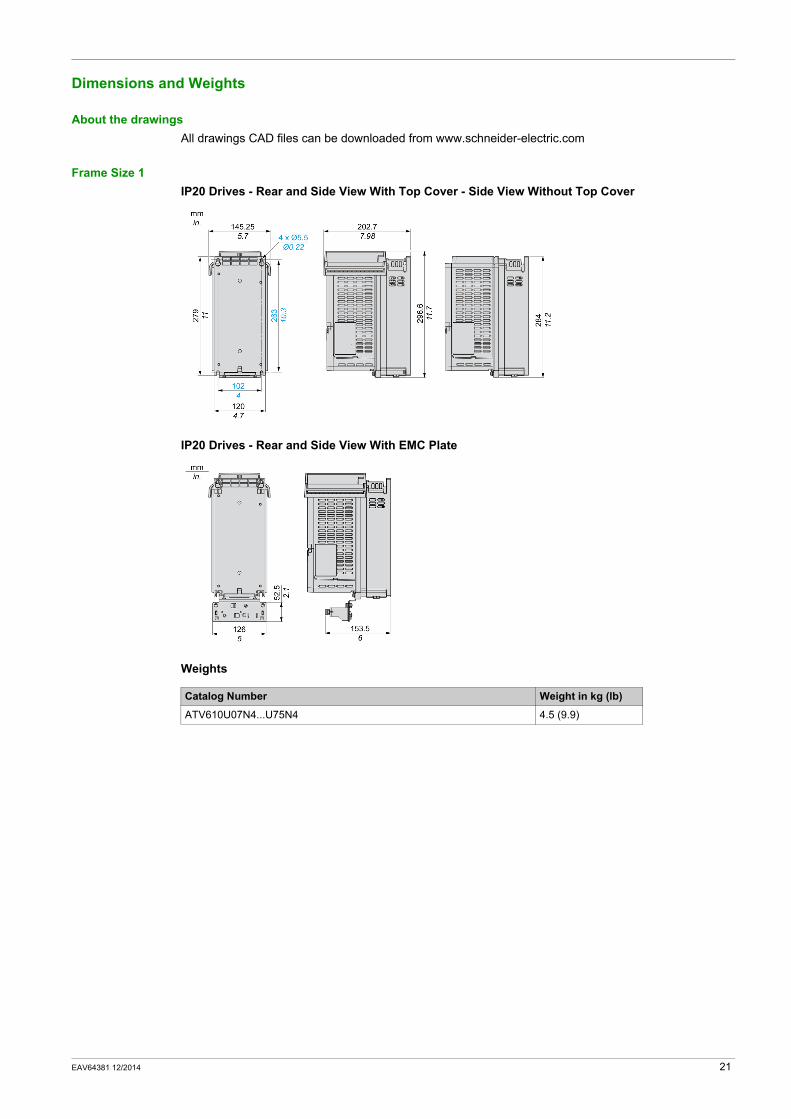
Dimensions and Weights
About the drawingsAll drawings CAD files can be downloaded from www.schneider-electric.com
Frame Size 1IP20 Drives - Rear and Side View With Top Cover - Side View Without Top Cover
IP20 Drives - Rear and Side View With EMC Plate
Weights
Catalog Number Weight in kg (lb)
ATV610U07N4...U75N4 4.5 (9.9)
EAV64381 12/2014 21
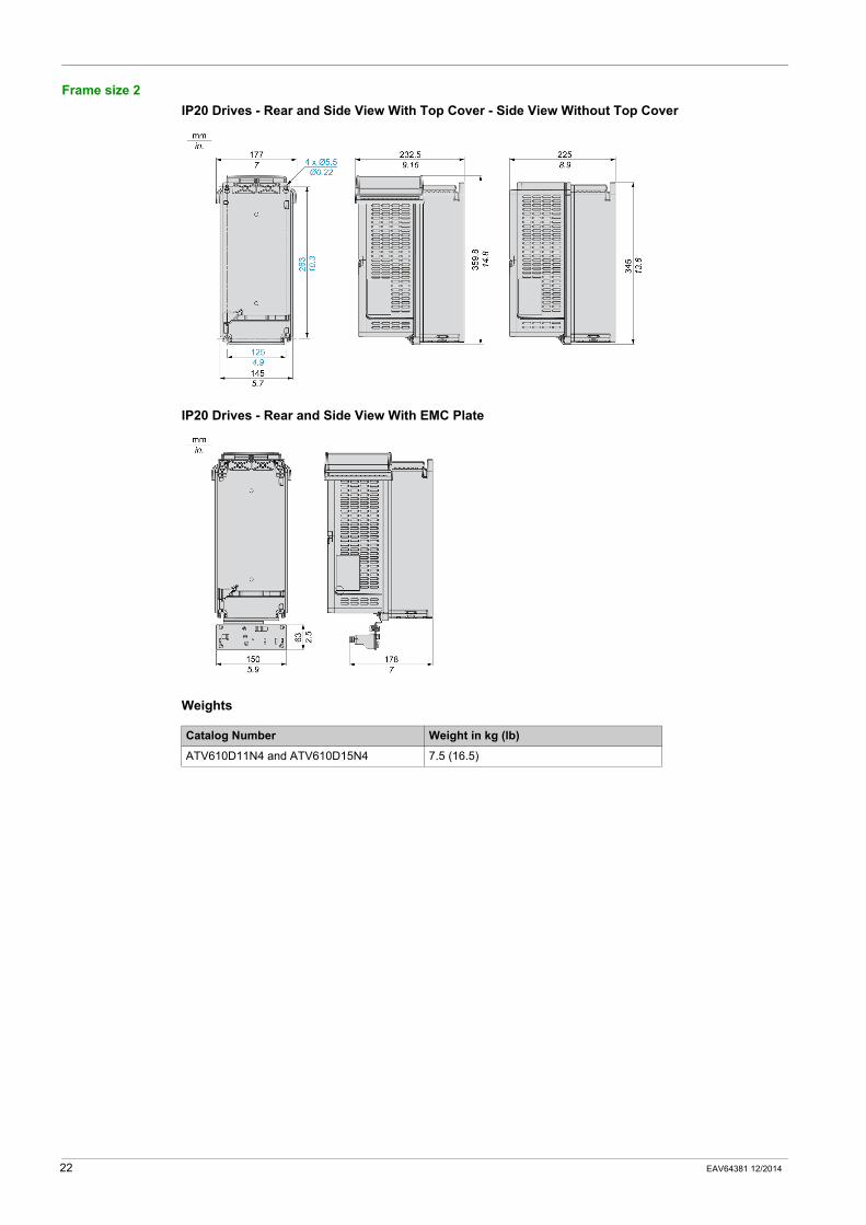
Frame size 2IP20 Drives - Rear and Side View With Top Cover - Side View Without Top Cover
IP20 Drives - Rear and Side View With EMC Plate
Weights
Catalog Number Weight in kg (lb)
ATV610D11N4 and ATV610D15N4 7.5 (16.5)
22 EAV64381 12/2014
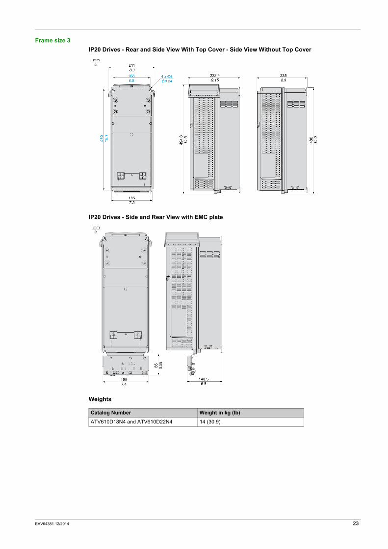
Frame size 3IP20 Drives - Rear and Side View With Top Cover - Side View Without Top Cover
IP20 Drives - Side and Rear View with EMC plate
Weights
Catalog Number Weight in kg (lb)
ATV610D18N4 and ATV610D22N4 14 (30.9)
EAV64381 12/2014 23
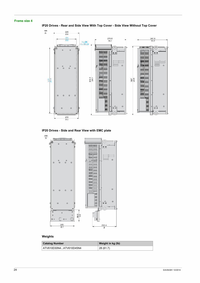
Frame size 4IP20 Drives - Rear and Side View With Top Cover - Side View Without Top Cover
IP20 Drives - Side and Rear View with EMC plate
Weights
Catalog Number Weight in kg (lb)
ATV610D30N4...ATV610D45N4 28 (61.7)
24 EAV64381 12/2014
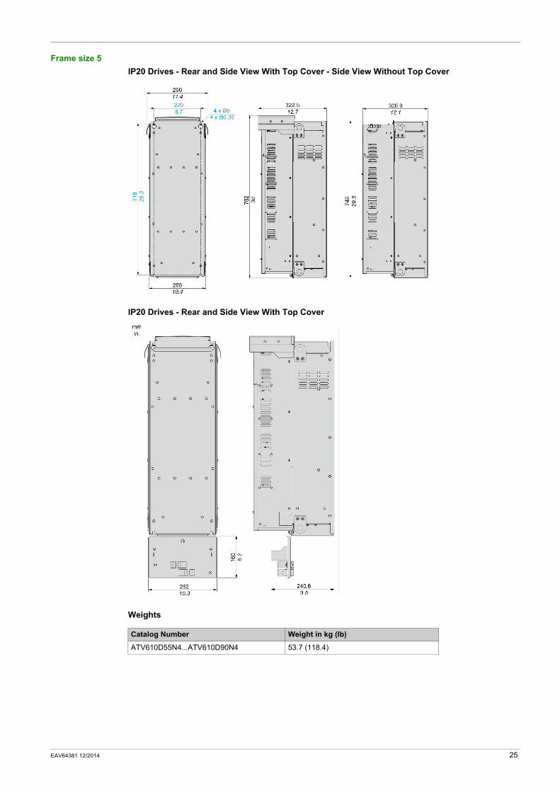
Frame size 5IP20 Drives - Rear and Side View With Top Cover - Side View Without Top Cover
IP20 Drives - Rear and Side View With Top Cover
Weights
Catalog Number Weight in kg (lb)
ATV610D55N4...ATV610D90N4 53.7 (118.4)
EAV64381 12/2014 25
Characteristics of the Power Part Terminals
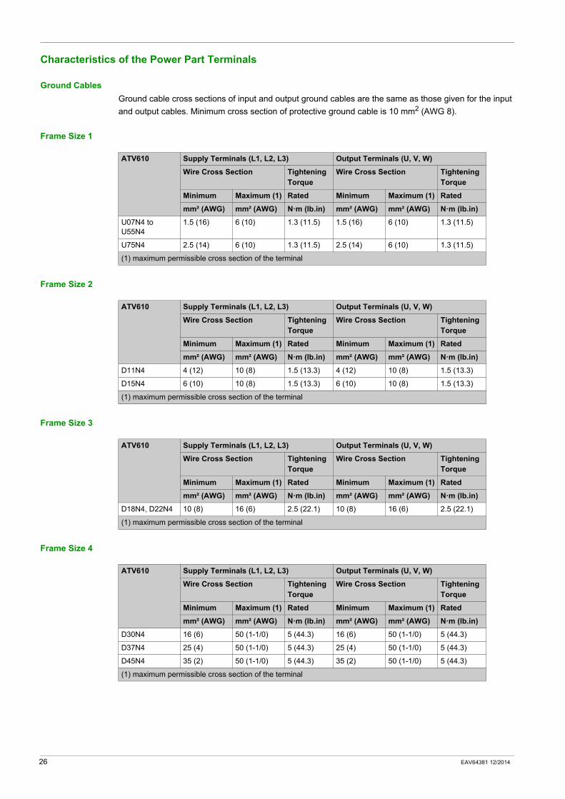
Ground CablesGround cable cross sections of input and output ground cables are the same as those given for the input and output cables. Minimum cross section of protective ground cable is 10 mm2 (AWG 8).
Frame Size 1
Frame Size 2
Frame Size 3
Frame Size 4
ATV610 Supply Terminals (L1, L2, L3) Output Terminals (U, V, W)
Wire Cross Section Tightening Torque
Wire Cross Section Tightening Torque
Minimum Maximum (1) Rated Minimum Maximum (1) Rated
mm² (AWG) mm² (AWG) N·m (lb.in) mm² (AWG) mm² (AWG) N·m (lb.in)
U07N4 to U55N4
1.5 (16) 6 (10) 1.3 (11.5) 1.5 (16) 6 (10) 1.3 (11.5)
U75N4 2.5 (14) 6 (10) 1.3 (11.5) 2.5 (14) 6 (10) 1.3 (11.5)
(1) maximum permissible cross section of the terminal
ATV610 Supply Terminals (L1, L2, L3) Output Terminals (U, V, W)
Wire Cross Section Tightening Torque
Wire Cross Section Tightening Torque
Minimum Maximum (1) Rated Minimum Maximum (1) Rated
mm² (AWG) mm² (AWG) N·m (lb.in) mm² (AWG) mm² (AWG) N·m (lb.in)
D11N4 4 (12) 10 (8) 1.5 (13.3) 4 (12) 10 (8) 1.5 (13.3)
D15N4 6 (10) 10 (8) 1.5 (13.3) 6 (10) 10 (8) 1.5 (13.3)
(1) maximum permissible cross section of the terminal
ATV610 Supply Terminals (L1, L2, L3) Output Terminals (U, V, W)
Wire Cross Section Tightening Torque
Wire Cross Section Tightening Torque
Minimum Maximum (1) Rated Minimum Maximum (1) Rated
mm² (AWG) mm² (AWG) N·m (lb.in) mm² (AWG) mm² (AWG) N·m (lb.in)
D18N4, D22N4 10 (8) 16 (6) 2.5 (22.1) 10 (8) 16 (6) 2.5 (22.1)
(1) maximum permissible cross section of the terminal
ATV610 Supply Terminals (L1, L2, L3) Output Terminals (U, V, W)
Wire Cross Section Tightening Torque
Wire Cross Section Tightening Torque
Minimum Maximum (1) Rated Minimum Maximum (1) Rated
mm² (AWG) mm² (AWG) N·m (lb.in) mm² (AWG) mm² (AWG) N·m (lb.in)
D30N4 16 (6) 50 (1-1/0) 5 (44.3) 16 (6) 50 (1-1/0) 5 (44.3)
D37N4 25 (4) 50 (1-1/0) 5 (44.3) 25 (4) 50 (1-1/0) 5 (44.3)
D45N4 35 (2) 50 (1-1/0) 5 (44.3) 35 (2) 50 (1-1/0) 5 (44.3)
(1) maximum permissible cross section of the terminal
26 EAV64381 12/2014
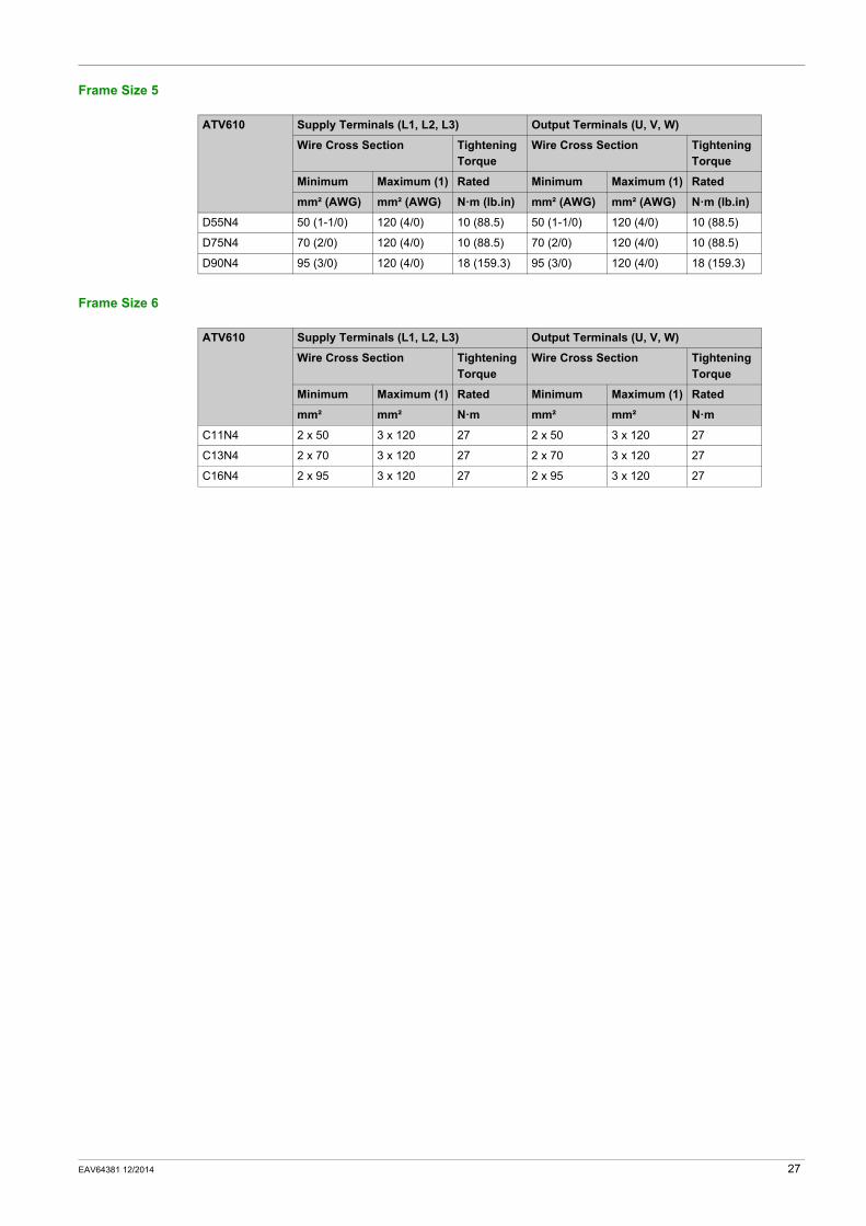
Frame Size 5
Frame Size 6
ATV610 Supply Terminals (L1, L2, L3) Output Terminals (U, V, W)
Wire Cross Section Tightening Torque
Wire Cross Section Tightening Torque
Minimum Maximum (1) Rated Minimum Maximum (1) Rated
mm² (AWG) mm² (AWG) N·m (lb.in) mm² (AWG) mm² (AWG) N·m (lb.in)
D55N4 50 (1-1/0) 120 (4/0) 10 (88.5) 50 (1-1/0) 120 (4/0) 10 (88.5)
D75N4 70 (2/0) 120 (4/0) 10 (88.5) 70 (2/0) 120 (4/0) 10 (88.5)
D90N4 95 (3/0) 120 (4/0) 18 (159.3) 95 (3/0) 120 (4/0) 18 (159.3)
ATV610 Supply Terminals (L1, L2, L3) Output Terminals (U, V, W)
Wire Cross Section Tightening Torque
Wire Cross Section Tightening Torque
Minimum Maximum (1) Rated Minimum Maximum (1) Rated
mm² mm² N·m mm² mm² N·m
C11N4 2 x 50 3 x 120 27 2 x 50 3 x 120 27
C13N4 2 x 70 3 x 120 27 2 x 70 3 x 120 27
C16N4 2 x 95 3 x 120 27 2 x 95 3 x 120 27
EAV64381 12/2014 27
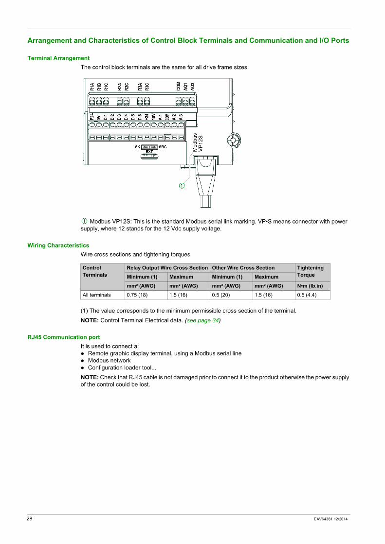
Arrangement and Characteristics of Control Block Terminals and Communication and I/O Ports
Terminal ArrangementThe control block terminals are the same for all drive frame sizes.
Modbus VP12S: This is the standard Modbus serial link marking. VP•S means connector with power supply, where 12 stands for the 12 Vdc supply voltage.
Wiring CharacteristicsWire cross sections and tightening torques
(1) The value corresponds to the minimum permissible cross section of the terminal.
NOTE: Control Terminal Electrical data. (see page 34)
RJ45 Communication portIt is used to connect a:
Remote graphic display terminal, using a Modbus serial lineModbus networkConfiguration loader tool...
NOTE: Check that RJ45 cable is not damaged prior to connect it to the product otherwise the power supply of the control could be lost.
Control Terminals
Relay Output Wire Cross Section Other Wire Cross Section Tightening TorqueMinimum (1) Maximum Minimum (1) Maximum
mm² (AWG) mm² (AWG) mm² (AWG) mm² (AWG) N•m (lb.in)
All terminals 0.75 (18) 1.5 (16) 0.5 (20) 1.5 (16) 0.5 (4.4)
28 EAV64381 12/2014
Electrical Data
Section 2.3Electrical Data
What Is in This Section?This section contains the following topics:
Topic Page
Drive Ratings 30
Derating Curves 31
Control Terminals Electrical Data 34
Sink / Source Switch Configuration 36
EAV64381 12/2014 29
Drive Ratings
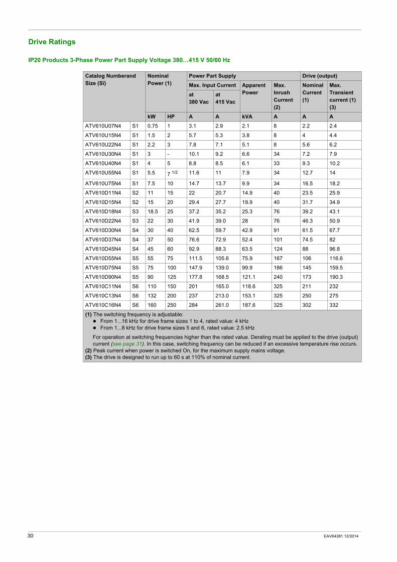
IP20 Products 3-Phase Power Part Supply Voltage 380…415 V 50/60 Hz
Catalog Numberand Size (Sï)
Nominal Power (1)
Power Part Supply Drive (output)
Max. Input Current ApparentPower
Max. Inrush Current (2)
NominalCurrent (1)
Max. Transient current (1) (3)
at380 Vac
at415 Vac
kW HP A A kVA A A A
ATV610U07N4 S1 0.75 1 3.1 2.9 2.1 8 2.2 2.4
ATV610U15N4 S1 1.5 2 5.7 5.3 3.8 8 4 4.4
ATV610U22N4 S1 2.2 3 7.8 7.1 5.1 8 5.6 6.2
ATV610U30N4 S1 3 - 10.1 9.2 6.6 34 7.2 7.9
ATV610U40N4 S1 4 5 8.8 8.5 6.1 33 9.3 10.2
ATV610U55N4 S1 5.5 7 1/2 11.6 11 7.9 34 12.7 14
ATV610U75N4 S1 7.5 10 14.7 13.7 9.9 34 16.5 18.2
ATV610D11N4 S2 11 15 22 20.7 14.9 40 23.5 25.9
ATV610D15N4 S2 15 20 29.4 27.7 19.9 40 31.7 34.9
ATV610D18N4 S3 18.5 25 37.2 35.2 25.3 76 39.2 43.1
ATV610D22N4 S3 22 30 41.9 39.0 28 76 46.3 50.9
ATV610D30N4 S4 30 40 62.5 59.7 42.9 91 61.5 67.7
ATV610D37N4 S4 37 50 76.6 72.9 52.4 101 74.5 82
ATV610D45N4 S4 45 60 92.9 88.3 63.5 124 88 96.8
ATV610D55N4 S5 55 75 111.5 105.6 75.9 167 106 116.6
ATV610D75N4 S5 75 100 147.9 139.0 99.9 186 145 159.5
ATV610D90N4 S5 90 125 177.8 168.5 121.1 240 173 190.3
ATV610C11N4 S6 110 150 201 165.0 118.6 325 211 232
ATV610C13N4 S6 132 200 237 213.0 153.1 325 250 275
ATV610C16N4 S6 160 250 284 261.0 187.6 325 302 332
(1) The switching frequency is adjustable:From 1...16 kHz for drive frame sizes 1 to 4, rated value: 4 kHzFrom 1...8 kHz for drive frame sizes 5 and 6, rated value: 2.5 kHz
For operation at switching frequencies higher than the rated value. Derating must be applied to the drive (output) current (see page 31). In this case, switching frequency can be reduced if an excessive temperature rise occurs.
(2) Peak current when power is switched On, for the maximum supply mains voltage.(3) The drive is designed to run up to 60 s at 110% of nominal current.
30 EAV64381 12/2014
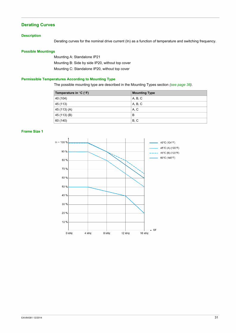
Derating Curves
DescriptionDerating curves for the nominal drive current (In) as a function of temperature and switching frequency.
Possible MountingsMounting A: Standalone IP21
Mounting B: Side by side IP20, without top cover
Mounting C: Standalone IP20, without top cover
Permissible Temperatures According to Mounting TypeThe possible mounting type are described in the Mounting Types section (see page 38).
Frame Size 1
Temperature in °C (°F) Mounting Type
40 (104) A, B, C
45 (113) A, B, C
45 (113) (A) A, C
45 (113) (B) B
60 (140) B, C
EAV64381 12/2014 31
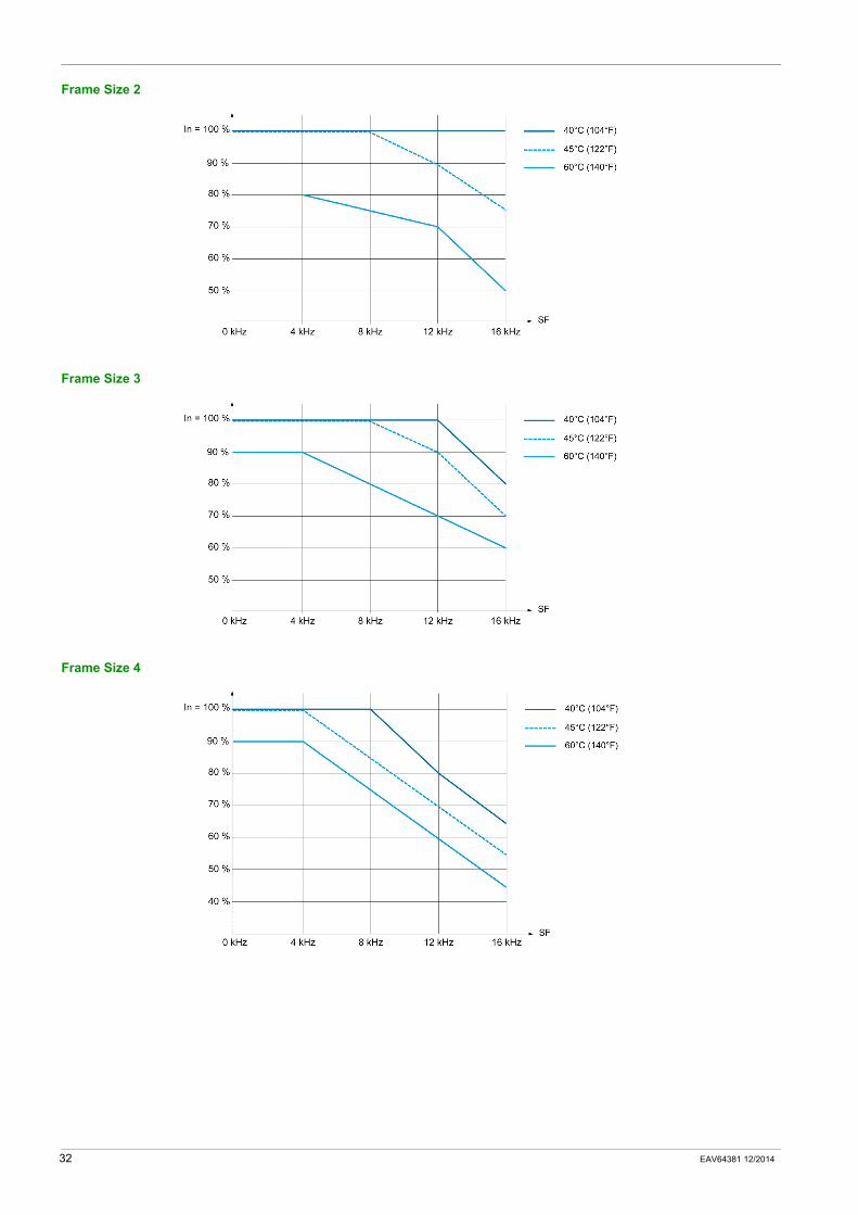
Frame Size 2
Frame Size 3
Frame Size 4
32 EAV64381 12/2014
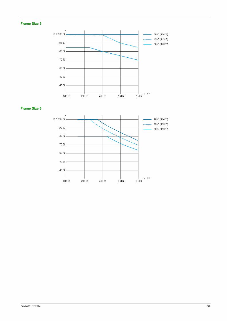
Frame Size 5
Frame Size 6
EAV64381 12/2014 33
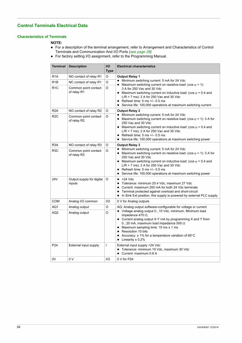
Control Terminals Electrical Data
Characteristics of TerminalsNOTE:
For a description of the terminal arrangement, refer to Arrangement and Characteristics of Control Terminals and Communication And I/O Ports (see page 28)For factory setting I/O assignment, refer to the Programming Manual.
Terminal Description I/O Type
Electrical characteristics
R1A NO contact of relay R1 O Output Relay 1Minimum switching current: 5 mA for 24 VdcMaximum switching current on resistive load: (cos ϕ = 1): 3 A for 250 Vac and 30 VdcMaximum switching current on inductive load: (cos ϕ = 0.4 and L/R = 7 ms): 2 A for 250 Vac and 30 VdcRefresh time: 5 ms +/– 0.5 msService life: 100,000 operations at maximum switching current
R1B NC contact of relay R1 O
R1C Common point contact of relay R1
O
R2A NO contact of relay R2 O Output Relay 2Minimum switching current: 5 mA for 24 VdcMaximum switching current on resistive load: (cos ϕ = 1): 3 A for 250 Vac and 30 VdcMaximum switching current on inductive load: (cos ϕ = 0.4 and L/R = 7 ms): 2 A for 250 Vac and 30 VdcRefresh time: 5 ms +/– 0.5 msService life: 100,000 operations at maximum switching power
R2C Common point contact of relay R2
O
R3A NO contact of relay R3 O Output Relay 3Minimum switching current: 5 mA for 24 VdcMaximum switching current on resistive load: (cos ϕ = 1): 3 A for 250 Vac and 30 VdcMaximum switching current on inductive load: (cos ϕ = 0.4 and L/R = 7 ms): 2 A for 250 Vac and 30 VdcRefresh time: 5 ms +/– 0.5 msService life: 100,000 operations at maximum switching power
R3C Common point contact of relay R3
O
24V Output supply for digital inputs
O +24 VdcTolerance: minimum 20.4 Vdc, maximum 27 VdcCurrent: maximum 200 mA for both 24 Vdc terminalsTerminal protected against overload and short-circuitIn Sink Ext position, this supply is powered by external PLC supply
COM Analog I/O common I/O 0 V for Analog outputs
AQ1 Analog output O AQ: Analog output software-configurable for voltage or currentVoltage analog output 0...10 Vdc, minimum. Minimum load impedance 470 Ω,Current analog output X-Y mA by programming X and Y from 0...20 mA, maximum load impedance 500 ΩMaximum sampling time: 10 ms ± 1 msResolution 10 bitsAccuracy: ± 1% for a temperature variation of 60°CLinearity ± 0.2%
AQ2 Analog output O
P24 External input supply I External input supply +24 VdcTolerance: minimum 19 Vdc, maximum 30 VdcCurrent: maximum 0.8 A
0V 0 V I/O 0 V for P24
34 EAV64381 12/2014
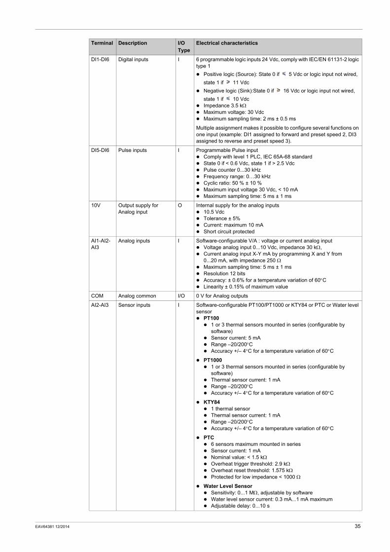
DI1-DI6 Digital inputs I 6 programmable logic inputs 24 Vdc, comply with IEC/EN 61131-2 logic type 1
Positive logic (Source): State 0 if 5 Vdc or logic input not wired, state 1 if 11 VdcNegative logic (Sink):State 0 if 16 Vdc or logic input not wired, state 1 if 10 VdcImpedance 3.5 kΩMaximum voltage: 30 VdcMaximum sampling time: 2 ms ± 0.5 ms
Multiple assignment makes it possible to configure several functions on one input (example: DI1 assigned to forward and preset speed 2, DI3 assigned to reverse and preset speed 3).
DI5-DI6 Pulse inputs I Programmable Pulse inputComply with level 1 PLC, IEC 65A-68 standardState 0 if < 0.6 Vdc, state 1 if > 2.5 VdcPulse counter 0...30 kHzFrequency range: 0…30 kHzCyclic ratio: 50 % ± 10 %Maximum input voltage 30 Vdc, < 10 mAMaximum sampling time: 5 ms ± 1 ms
10V Output supply for Analog input
O Internal supply for the analog inputs10.5 VdcTolerance ± 5% Current: maximum 10 mAShort circuit protected
AI1-AI2-AI3
Analog inputs I Software-configurable V/A : voltage or current analog inputVoltage analog input 0...10 Vdc, impedance 30 kΩ,Current analog input X-Y mA by programming X and Y from 0...20 mA, with impedance 250 ΩMaximum sampling time: 5 ms ± 1 msResolution 12 bitsAccuracy: ± 0.6% for a temperature variation of 60°CLinearity ± 0.15% of maximum value
COM Analog common I/O 0 V for Analog outputs
AI2-AI3 Sensor inputs I Software-configurable PT100/PT1000 or KTY84 or PTC or Water level sensor
PT1001 or 3 thermal sensors mounted in series (configurable by software)Sensor current: 5 mARange –20/200°CAccuracy +/– 4°C for a temperature variation of 60°C
PT10001 or 3 thermal sensors mounted in series (configurable by software)Thermal sensor current: 1 mARange –20/200°CAccuracy +/– 4°C for a temperature variation of 60°C
KTY841 thermal sensorThermal sensor current: 1 mARange –20/200°CAccuracy +/– 4°C for a temperature variation of 60°C
PTC6 sensors maximum mounted in seriesSensor current: 1 mANominal value: < 1.5 kΩOverheat trigger threshold: 2.9 kΩOverheat reset threshold: 1.575 kΩProtected for low impedance < 1000 Ω
Water Level SensorSensitivity: 0...1 MΩ, adjustable by softwareWater level sensor current: 0.3 mA...1 mA maximumAdjustable delay: 0...10 s
Terminal Description I/O Type
Electrical characteristics
EAV64381 12/2014 35
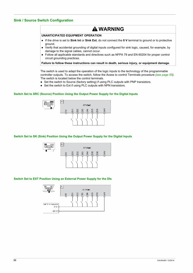
Sink / Source Switch Configuration
The switch is used to adapt the operation of the logic inputs to the technology of the programmable controller outputs. To access the switch, follow the Acess to control Terminals procedure (see page 55). The switch is located below the control terminals.
Set the switch to Source (factory setting) if using PLC outputs with PNP transistors.Set the switch to Ext if using PLC outputs with NPN transistors.
Switch Set to SRC (Source) Position Using the Output Power Supply for the Digital Inputs
Switch Set to SK (Sink) Position Using the Output Power Supply for the Digital Inputs
Switch Set to EXT Position Using an External Power Supply for the DIs
WARNINGUNANTICIPATED EQUIPMENT OPERATION
If the drive is set to Sink Int or Sink Ext, do not connect the 0 V terminal to ground or to protective ground.Verify that accidental grounding of digital inputs configured for sink logic, caused, for example, by damage to the signal cables, cannot occur.Follow all applicable standards and directives such as NFPA 79 and EN 60204 for proper control circuit grounding practices.
Failure to follow these instructions can result in death, serious injury, or equipment damage.
36 EAV64381 12/2014

Altivar 610
EAV64381 12/2014
Drive Mounting
Chapter 3Drive Mounting
What Is in This Chapter?This chapter contains the following topics:
Topic Page
Mounting Conditions 38
Mounting Procedures 41
EAV64381 12/2014 37
Mounting Conditions
Before You Begin
The metal surfaces of the product may exceed 100 °C (212 °F) during operation.
Attaching A Label With Safety Instructions
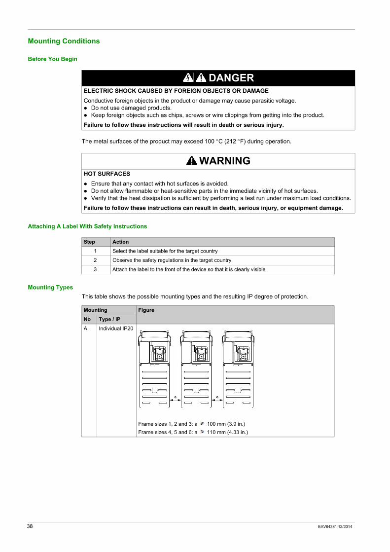
Mounting TypesThis table shows the possible mounting types and the resulting IP degree of protection.
DANGERELECTRIC SHOCK CAUSED BY FOREIGN OBJECTS OR DAMAGEConductive foreign objects in the product or damage may cause parasitic voltage.
Do not use damaged products.Keep foreign objects such as chips, screws or wire clippings from getting into the product.
Failure to follow these instructions will result in death or serious injury.
WARNINGHOT SURFACES
Ensure that any contact with hot surfaces is avoided.Do not allow flammable or heat-sensitive parts in the immediate vicinity of hot surfaces.Verify that the heat dissipation is sufficient by performing a test run under maximum load conditions.
Failure to follow these instructions can result in death, serious injury, or equipment damage.
Step Action
1 Select the label suitable for the target country
2 Observe the safety regulations in the target country
3 Attach the label to the front of the device so that it is clearly visible
Mounting Figure
No Type / IP
A Individual IP20
Frame sizes 1, 2 and 3: a 100 mm (3.9 in.)Frame sizes 4, 5 and 6: a 110 mm (4.33 in.)
38 EAV64381 12/2014
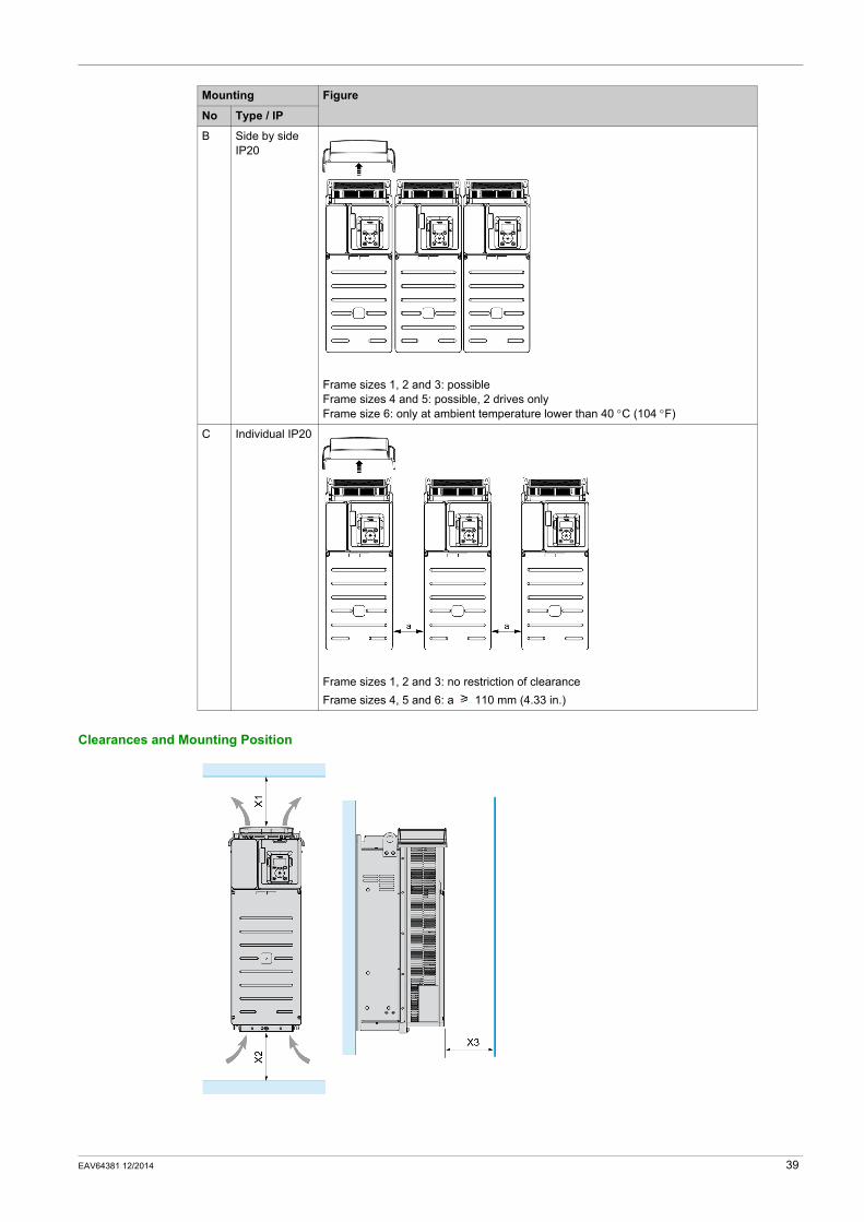
Clearances and Mounting Position
B Side by side IP20
Frame sizes 1, 2 and 3: possibleFrame sizes 4 and 5: possible, 2 drives onlyFrame size 6: only at ambient temperature lower than 40 °C (104 °F)
C Individual IP20
Frame sizes 1, 2 and 3: no restriction of clearanceFrame sizes 4, 5 and 6: a 110 mm (4.33 in.)
Mounting Figure
No Type / IP
EAV64381 12/2014 39
Minimum clearance regarding the drive frame size
X1: free space in top of the drive
X2: free space in bottom of the drive
X3: free space in front of the drive
General Mounting InstructionsMount the device in a vertical position (±10°). This is required for cooling the device.Attach it on the mounting surface in compliance with standards, using 4 screws with captive washer according to the table given in Mounting Procedures.The use of washers is required with all mounting screws.Tighten the fixation screws with respect to the tightening torques given in this manual.Do not mount the device close to heat sources.Avoid heat accumulations.Adhere to the minimum installation distances for required cooling.Do not mount the device on flammable materials.
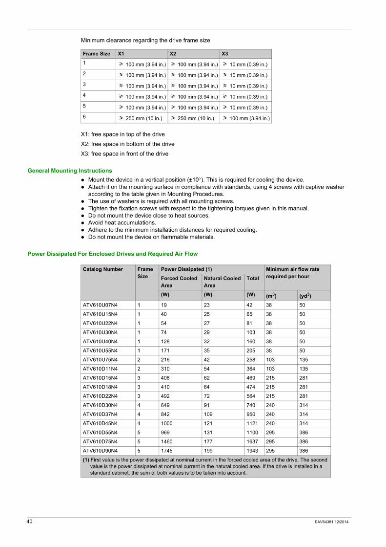
Power Dissipated For Enclosed Drives and Required Air Flow
Frame Size X1 X2 X3
1 100 mm (3.94 in.) 100 mm (3.94 in.) 10 mm (0.39 in.)
2 100 mm (3.94 in.) 100 mm (3.94 in.) 10 mm (0.39 in.)
3 100 mm (3.94 in.) 100 mm (3.94 in.) 10 mm (0.39 in.)
4 100 mm (3.94 in.) 100 mm (3.94 in.) 10 mm (0.39 in.)
5 100 mm (3.94 in.) 100 mm (3.94 in.) 10 mm (0.39 in.)
6 250 mm (10 in.) 250 mm (10 in.) 100 mm (3.94 in.)
Catalog Number Frame Size
Power Dissipated (1) Minimum air flow rate required per hourForced Cooled
AreaNatural Cooled Area
Total
(W) (W) (W) (m3) (yd3)
ATV610U07N4 1 19 23 42 38 50
ATV610U15N4 1 40 25 65 38 50
ATV610U22N4 1 54 27 81 38 50
ATV610U30N4 1 74 29 103 38 50
ATV610U40N4 1 128 32 160 38 50
ATV610U55N4 1 171 35 205 38 50
ATV610U75N4 2 216 42 258 103 135
ATV610D11N4 2 310 54 364 103 135
ATV610D15N4 3 408 62 469 215 281
ATV610D18N4 3 410 64 474 215 281
ATV610D22N4 3 492 72 564 215 281
ATV610D30N4 4 649 91 740 240 314
ATV610D37N4 4 842 109 950 240 314
ATV610D45N4 4 1000 121 1121 240 314
ATV610D55N4 5 969 131 1100 295 386
ATV610D75N4 5 1460 177 1637 295 386
ATV610D90N4 5 1745 199 1943 295 386
(1) First value is the power dissipated at nominal current in the forced cooled area of the drive. The second value is the power dissipated at nominal current in the natural cooled area. If the drive is installed in a standard cabinet, the sum of both values is to be taken into account.
40 EAV64381 12/2014
Mounting Procedures
Mounting Screws
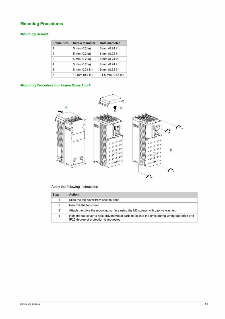
Mounting Procedure For Frame Sizes 1 to 4
Apply the following instructions
Frame Size Screw diameter Hole diameter
1 5 mm (0.2 in) 6 mm (0.24 in)
2 5 mm (0.2 in) 6 mm (0.24 in)
3 5 mm (0.2 in) 6 mm (0.24 in)
4 5 mm (0.2 in) 6 mm (0.24 in)
5 8 mm (0.31 in) 9 mm (0.35 in)
6 10 mm (0.4 in) 11.5 mm (0.45 in)
Step Action
1 Slide the top cover from back to front
2 Remove the top cover
3 Attach the drive the mounting surface using the M5 screws with captive washer.
4 Refit the top cover to help prevent metal parts to fall into the drive during wiring operation or if IP20 degree of protection is requested.
EAV64381 12/2014 41
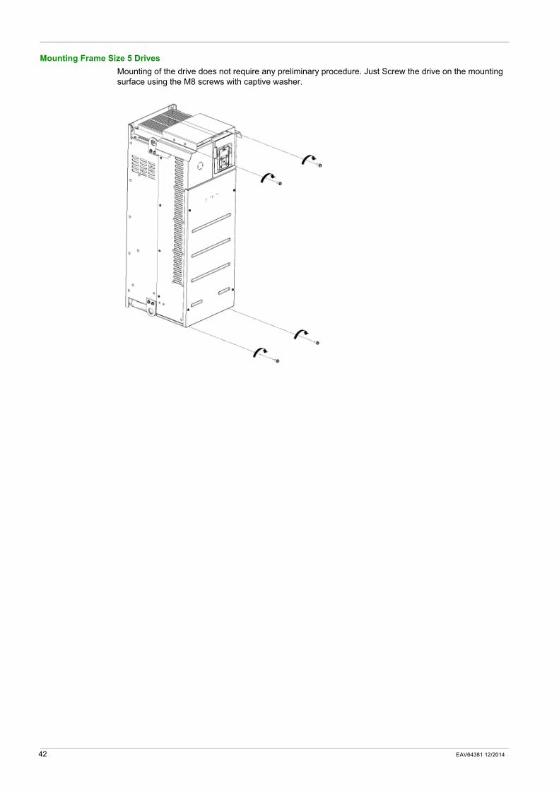
Mounting Frame Size 5 DrivesMounting of the drive does not require any preliminary procedure. Just Screw the drive on the mounting surface using the M8 screws with captive washer.
42 EAV64381 12/2014
Altivar 610
EAV64381 12/2014
Drive wiring
Chapter 4Drive wiring
What Is in This Chapter?This chapter contains the following topics:
Topic Page
Wiring Instructions 44
Cable Length Instructions 46
Wiring Diagrams 47
Wiring the Power Part 49
Electromagnetic Compatibility 51
Operation on an IT or Corner Grounded System 53
Wiring The Control Part 55
EAV64381 12/2014 43
Wiring Instructions
General Instructions
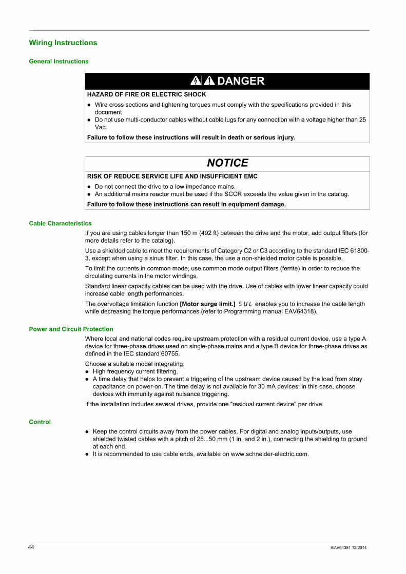
Cable CharacteristicsIf you are using cables longer than 150 m (492 ft) between the drive and the motor, add output filters (for more details refer to the catalog).
Use a shielded cable to meet the requirements of Category C2 or C3 according to the standard IEC 61800-3, except when using a sinus filter. In this case, the use a non-shielded motor cable is possible.
To limit the currents in common mode, use common mode output filters (ferrite) in order to reduce the circulating currents in the motor windings.
Standard linear capacity cables can be used with the drive. Use of cables with lower linear capacity could increase cable length performances.
The overvoltage limitation function [Motor surge limit.] SUL enables you to increase the cable length while decreasing the torque performances (refer to Programming manual EAV64318).
Power and Circuit ProtectionWhere local and national codes require upstream protection with a residual current device, use a type A device for three-phase drives used on single-phase mains and a type B device for three-phase drives as defined in the IEC standard 60755.
Choose a suitable model integrating:High frequency current filtering,A time delay that helps to prevent a triggering of the upstream device caused by the load from stray capacitance on power-on. The time delay is not available for 30 mA devices; in this case, choose devices with immunity against nuisance triggering.
If the installation includes several drives, provide one "residual current device" per drive.
ControlKeep the control circuits away from the power cables. For digital and analog inputs/outputs, use shielded twisted cables with a pitch of 25...50 mm (1 in. and 2 in.), connecting the shielding to ground at each end.It is recommended to use cable ends, available on www.schneider-electric.com.
DANGERHAZARD OF FIRE OR ELECTRIC SHOCK
Wire cross sections and tightening torques must comply with the specifications provided in this documentDo not use multi-conductor cables without cable lugs for any connection with a voltage higher than 25 Vac.
Failure to follow these instructions will result in death or serious injury.
NOTICERISK OF REDUCE SERVICE LIFE AND INSUFFICIENT EMC
Do not connect the drive to a low impedance mains.An additional mains reactor must be used if the SCCR exceeds the value given in the catalog.
Failure to follow these instructions can result in equipment damage.
44 EAV64381 12/2014
Equipment Grounding
Tighten the grounding screws according to the instructions given in the Ground Cables section (see page 26).
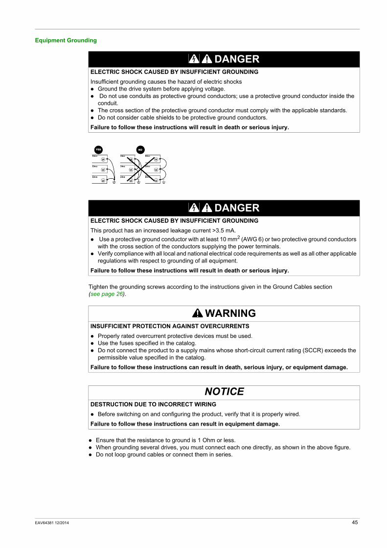
Ensure that the resistance to ground is 1 Ohm or less.When grounding several drives, you must connect each one directly, as shown in the above figure.Do not loop ground cables or connect them in series.
DANGERELECTRIC SHOCK CAUSED BY INSUFFICIENT GROUNDINGInsufficient grounding causes the hazard of electric shocks
Ground the drive system before applying voltage. Do not use conduits as protective ground conductors; use a protective ground conductor inside the conduit.The cross section of the protective ground conductor must comply with the applicable standards.Do not consider cable shields to be protective ground conductors.
Failure to follow these instructions will result in death or serious injury.
DANGERELECTRIC SHOCK CAUSED BY INSUFFICIENT GROUNDINGThis product has an increased leakage current >3.5 mA.
Use a protective ground conductor with at least 10 mm2 (AWG 6) or two protective ground conductors with the cross section of the conductors supplying the power terminals.Verify compliance with all local and national electrical code requirements as well as all other applicable regulations with respect to grounding of all equipment.
Failure to follow these instructions will result in death or serious injury.
WARNINGINSUFFICIENT PROTECTION AGAINST OVERCURRENTS
Properly rated overcurrent protective devices must be used.Use the fuses specified in the catalog.Do not connect the product to a supply mains whose short-circuit current rating (SCCR) exceeds the permissible value specified in the catalog.
Failure to follow these instructions can result in death, serious injury, or equipment damage.
NOTICEDESTRUCTION DUE TO INCORRECT WIRING
Before switching on and configuring the product, verify that it is properly wired.
Failure to follow these instructions can result in equipment damage.
EAV64381 12/2014 45
Cable Length Instructions
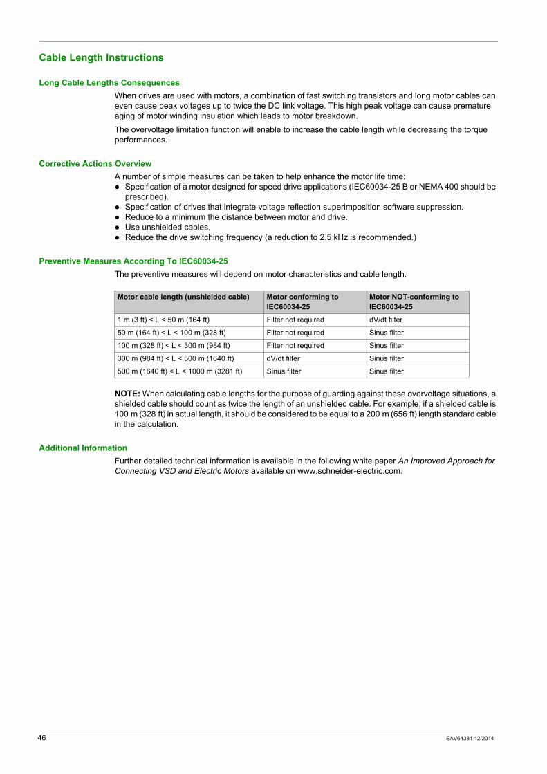
Long Cable Lengths ConsequencesWhen drives are used with motors, a combination of fast switching transistors and long motor cables can even cause peak voltages up to twice the DC link voltage. This high peak voltage can cause premature aging of motor winding insulation which leads to motor breakdown.
The overvoltage limitation function will enable to increase the cable length while decreasing the torque performances.
Corrective Actions OverviewA number of simple measures can be taken to help enhance the motor life time:
Specification of a motor designed for speed drive applications (IEC60034-25 B or NEMA 400 should be prescribed).Specification of drives that integrate voltage reflection superimposition software suppression.Reduce to a minimum the distance between motor and drive.Use unshielded cables. Reduce the drive switching frequency (a reduction to 2.5 kHz is recommended.)
Preventive Measures According To IEC60034-25The preventive measures will depend on motor characteristics and cable length.
NOTE: When calculating cable lengths for the purpose of guarding against these overvoltage situations, a shielded cable should count as twice the length of an unshielded cable. For example, if a shielded cable is 100 m (328 ft) in actual length, it should be considered to be equal to a 200 m (656 ft) length standard cable in the calculation.
Additional InformationFurther detailed technical information is available in the following white paper An Improved Approach for Connecting VSD and Electric Motors available on www.schneider-electric.com.
Motor cable length (unshielded cable) Motor conforming to IEC60034-25
Motor NOT-conforming to IEC60034-25
1 m (3 ft) < L < 50 m (164 ft) Filter not required dV/dt filter
50 m (164 ft) < L < 100 m (328 ft) Filter not required Sinus filter
100 m (328 ft) < L < 300 m (984 ft) Filter not required Sinus filter
300 m (984 ft) < L < 500 m (1640 ft) dV/dt filter Sinus filter
500 m (1640 ft) < L < 1000 m (3281 ft) Sinus filter Sinus filter
46 EAV64381 12/2014
Wiring Diagrams
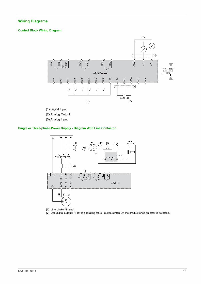
Control Block Wiring Diagram
(1) Digital Input
(2) Analog Output
(3) Analog Input
Single or Three-phase Power Supply - Diagram With Line Contactor
(1) Line choke (if used).(2) Use digital output R1 set to operating state Fault to switch Off the product once an error is detected.
EAV64381 12/2014 47
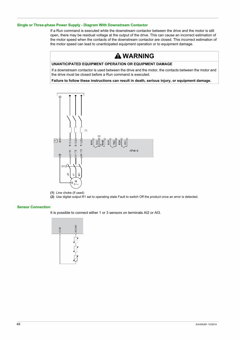
Single or Three-phase Power Supply - Diagram With Downstream ContactorIf a Run command is executed while the downstream contactor between the drive and the motor is still open, there may be residual voltage at the output of the drive. This can cause an incorrect estimation of the motor speed when the contacts of the downstream contactor are closed. This incorrect estimation of the motor speed can lead to unanticipated equipment operation or to equipment damage.
(1) Line choke (if used)(2) Use digital output R1 set to operating state Fault to switch Off the product once an error is detected.
Sensor ConnectionIt is possible to connect either 1 or 3 sensors on terminals AI2 or AI3.
WARNINGUNANTICIPATED EQUIPMENT OPERATION OR EQUIPMENT DAMAGEIf a downstream contactor is used between the drive and the motor, the contacts between the motor and the drive must be closed before a Run command is executed.
Failure to follow these instructions can result in death, serious injury, or equipment damage.
48 EAV64381 12/2014
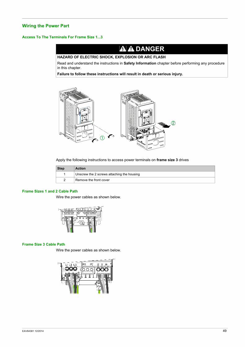
Wiring the Power Part
Access To The Terminals For Frame Size 1...3
Apply the following instructions to access power terminals on frame size 3 drives
Frame Sizes 1 and 2 Cable PathWire the power cables as shown below.
Frame Size 3 Cable PathWire the power cables as shown below.
DANGERHAZARD OF ELECTRIC SHOCK, EXPLOSION OR ARC FLASHRead and understand the instructions in Safety Information chapter before performing any procedure in this chapter.
Failure to follow these instructions will result in death or serious injury.
Step Action
1 Unscrew the 2 screws attaching the housing
2 Remove the front cover
EAV64381 12/2014 49
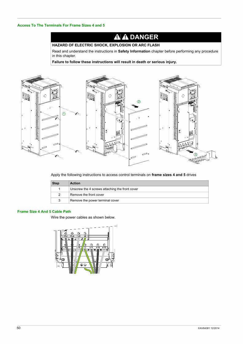
Access To The Terminals For Frame Sizes 4 and 5
Apply the following instructions to access control terminals on frame sizes 4 and 5 drives
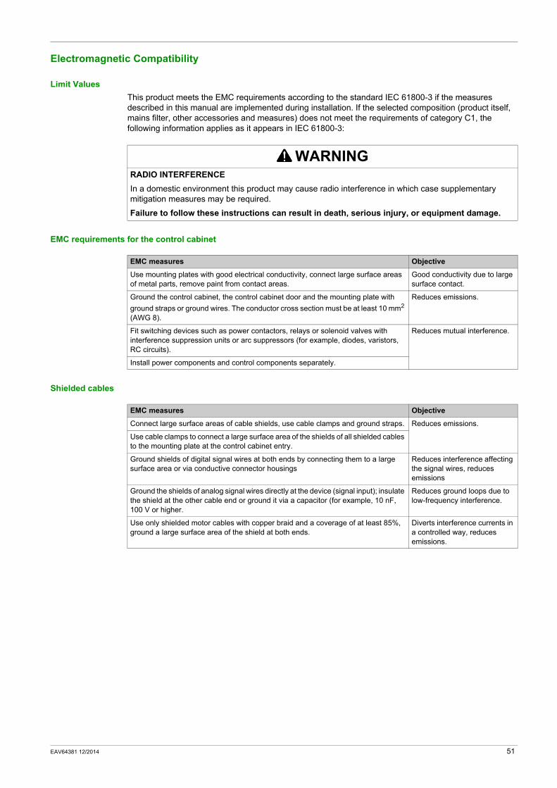
Frame Size 4 And 5 Cable PathWire the power cables as shown below.
DANGERHAZARD OF ELECTRIC SHOCK, EXPLOSION OR ARC FLASHRead and understand the instructions in Safety Information chapter before performing any procedure in this chapter.
Failure to follow these instructions will result in death or serious injury.
Step Action
1 Unscrew the 4 screws attaching the front cover
2 Remove the front cover
3 Remove the power terminal cover
50 EAV64381 12/2014
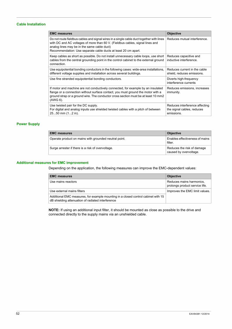
Electromagnetic Compatibility
Limit ValuesThis product meets the EMC requirements according to the standard IEC 61800-3 if the measures described in this manual are implemented during installation. If the selected composition (product itself, mains filter, other accessories and measures) does not meet the requirements of category C1, the following information applies as it appears in IEC 61800-3:
EMC requirements for the control cabinet
Shielded cables
WARNINGRADIO INTERFERENCEIn a domestic environment this product may cause radio interference in which case supplementary mitigation measures may be required.
Failure to follow these instructions can result in death, serious injury, or equipment damage.
EMC measures Objective
Use mounting plates with good electrical conductivity, connect large surface areas of metal parts, remove paint from contact areas.
Good conductivity due to large surface contact.
Ground the control cabinet, the control cabinet door and the mounting plate with ground straps or ground wires. The conductor cross section must be at least 10 mm2 (AWG 8).
Reduces emissions.
Fit switching devices such as power contactors, relays or solenoid valves with interference suppression units or arc suppressors (for example, diodes, varistors, RC circuits).
Reduces mutual interference.
Install power components and control components separately.
EMC measures Objective
Connect large surface areas of cable shields, use cable clamps and ground straps. Reduces emissions.
Use cable clamps to connect a large surface area of the shields of all shielded cables to the mounting plate at the control cabinet entry.
Ground shields of digital signal wires at both ends by connecting them to a large surface area or via conductive connector housings
Reduces interference affecting the signal wires, reduces emissions
Ground the shields of analog signal wires directly at the device (signal input); insulate the shield at the other cable end or ground it via a capacitor (for example, 10 nF, 100 V or higher.
Reduces ground loops due to low-frequency interference.
Use only shielded motor cables with copper braid and a coverage of at least 85%, ground a large surface area of the shield at both ends.
Diverts interference currents in a controlled way, reduces emissions.
EAV64381 12/2014 51
Cable Installation
Power Supply
Additional measures for EMC improvementDepending on the application, the following measures can improve the EMC-dependent values:
NOTE: If using an additional input filter, it should be mounted as close as possible to the drive and connected directly to the supply mains via an unshielded cable.
EMC measures Objective
Do not route fieldbus cables and signal wires in a single cable duct together with lines with DC and AC voltages of more than 60 V. (Fieldbus cables, signal lines and analog lines may be in the same cable duct)Recommendation: Use separate cable ducts at least 20 cm apart.
Reduces mutual interference.
Keep cables as short as possible. Do not install unnecessary cable loops, use short cables from the central grounding point in the control cabinet to the external ground connection.
Reduces capacitive and inductive interference.
Use equipotential bonding conductors in the following cases: wide-area installations, different voltage supplies and installation across several buildings.
Reduces current in the cable shield, reduces emissions.
Use fine stranded equipotential bonding conductors. Diverts high-frequency interference currents
If motor and machine are not conductively connected, for example by an insulated flange or a connection without surface contact, you must ground the motor with a ground strap or a ground wire. The conductor cross section must be at least 10 mm2 (AWG 6).
Reduces emissions, increases immunity.
Use twisted pair for the DC supply.For digital and analog inputs use shielded twisted cables with a pitch of between 25...50 mm (1...2 in).
Reduces interference affecting the signal cables, reduces emissions.
EMC measures Objective
Operate product on mains with grounded neutral point. Enables effectiveness of mains filter.
Surge arrester if there is a risk of overvoltage. Reduces the risk of damage caused by overvoltage.
EMC measures Objective
Use mains reactors Reduces mains harmonics, prolongs product service life.
Use external mains filters Improves the EMC limit values.
Additional EMC measures, for example mounting in a closed control cabinet with 15 dB shielding attenuation of radiated interference
52 EAV64381 12/2014
Operation on an IT or Corner Grounded System
DefinitionIT system: Isolated or impedance grounded neutral. Use a permanent insulation monitoring device compatible with nonlinear loads, such as an XM200 type or equivalent.
Corner grounded system: System with one phase grounded.
Operation
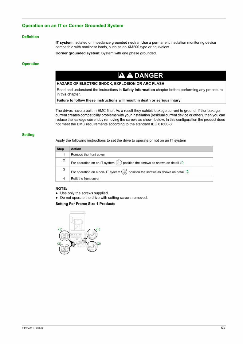
The drives have a built-in EMC filter. As a result they exhibit leakage current to ground. If the leakage current creates compatibility problems with your installation (residual current device or other), then you can reduce the leakage current by removing the screws as shown below. In this configuration the product does not meet the EMC requirements according to the standard IEC 61800-3.
SettingApply the following instructions to set the drive to operate or not on an IT system
NOTE: Use only the screws supplied.Do not operate the drive with setting screws removed.
Setting For Frame Size 1 Products
DANGERHAZARD OF ELECTRIC SHOCK, EXPLOSION OR ARC FLASHRead and understand the instructions in Safety Information chapter before performing any procedure in this chapter.
Failure to follow these instructions will result in death or serious injury.
Step Action
1 Remove the front cover
2For operation on an IT system position the screws as shown on detail
3For operation on a non- IT system position the screws as shown on detail
4 Refit the front cover
EAV64381 12/2014 53
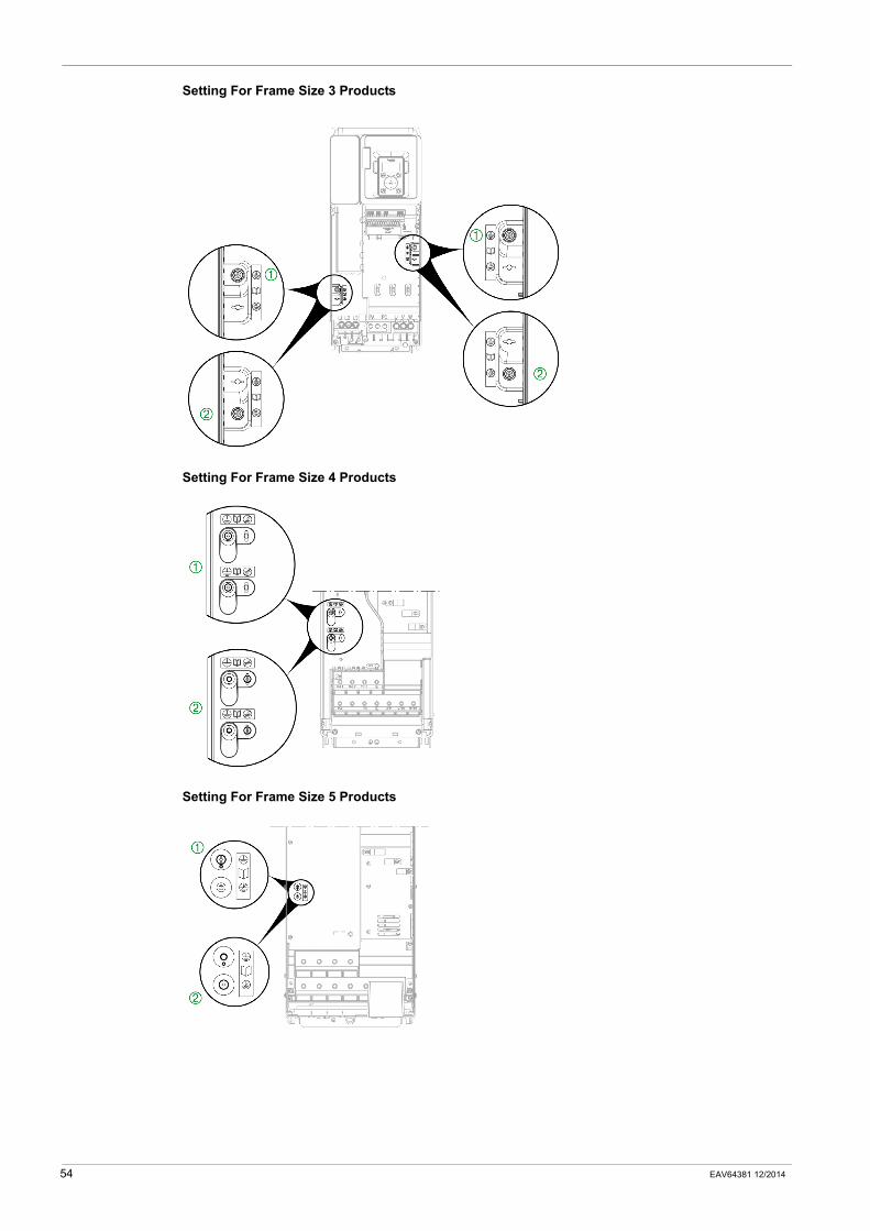
Setting For Frame Size 3 Products
Setting For Frame Size 4 Products
Setting For Frame Size 5 Products
54 EAV64381 12/2014
Wiring The Control Part
Preliminary Steps
Access to the Terminals
To access the control terminals, refer to the procedure described in the Wiring the Power Part chapter (see page 49).
DANGERHAZARD OF ELECTRIC SHOCK, EXPLOSION OR ARC FLASHRead and understand the instructions in Safety Information chapter before performing any procedure in this chapter.
Failure to follow these instructions will result in death or serious injury.
WARNINGUNINTENDED BEHAVIOR OF INPUTS AND OUTPUTSThe functions of the inputs and outputs depend on the selected operating mode and the settings of the corresponding parameters.
Verify that the wiring is appropriate for the settings.Only start the system if there are no persons or obstructions in the hazardous area.When commissioning, carefully run tests for all operating states and potential error situations.
Failure to follow these instructions can result in death, serious injury, or equipment damage.
DANGERHAZARD OF ELECTRIC SHOCK, EXPLOSION OR ARC FLASHRead and understand the instructions in Safety Information chapter before performing any procedure in this chapter.
Failure to follow these instructions will result in death or serious injury.
EAV64381 12/2014 55

56 EAV64381 12/2014

Altivar 610
EAV64381 12/2014
Checking Installation
Chapter 5Checking Installation
Check List Before Switching On
Mechanical InstallationVerify the mechanical installation of the entire drive system:
Electrical installationVerify the electrical connections and the cabling:
Covers And SealsVerify that all covers and seals of the control cabinet are properly installed to meet the required degree of protection.
Step Action
1 Does the installation meet the specified distance requirements?
2 Did you tighten all fastening screws with the specified tightening torque?
Step Action
1 Did you connect all protective ground conductors?
2 Do all fuses and circuit breaker have the correct rating; are the fuses of the specified type? (refer to the catalog).
3 Did you connect or insulate all wires at the cable ends?
4 Did you properly connect and install all cables and connectors?
5 Do all plug-in terminals colors and markings correspond to the colors and marking of the control block?
6 Did you properly connect the signal wires?
7 Are the required shield connections EMC-compliant?
8 Did you take all measures for EMC compliance?
EAV64381 12/2014 57

58 EAV64381 12/2014
Altivar 610
EAV64381 12/2014
Maintenance
Chapter 6Maintenance
Scheduled servicing
Servicing
NOTE: The fan operation depends of the drive thermal state. The drive may be running and the fan not.
Diagnostic And TroubleshootingRefer to the Programming Manual available on www.schneider-electric.com.
Spares and repairsServiceable product. Please refer to your Customer Care Center.
DANGERHAZARD OF ELECTRIC SHOCK, EXPLOSION OR ARC FLASHRead and understand the instructions in Safety Information chapter before performing any procedure in this chapter.
Failure to follow these instructions will result in death or serious injury.
WARNINGHOT SURFACES
Ensure that any contact with hot surfaces is avoided.Do not allow flammable or heat-sensitive parts in the immediate vicinity of hot surfaces.Verify that the heat dissipation is sufficient by performing a test run under maximum load conditions.
Failure to follow these instructions can result in death, serious injury, or equipment damage.
NOTICERISK OF DAMAGE TO THE DRIVEPerform the following activities.
Failure to follow these instructions can result in equipment damage.
Environment Part concerned Action Periodicity
Knock on the product
Housing - control block (led - display)
Verify the drive visual aspect At least each year
Corrosion Terminals - connector - screws - EMC plate
Inspect and clean if required
Dust Terminals - fans - blowholes - enclosures air inlets and outlets - cabinets air filters
Inspect and clean if required
Temperature Around the product Verify and correct if required
Cooling Fan Verify the fan operation At least each year
Replace the fan, see catalog and the instructions sheets on www.schneider-electric.com.
After 3 to 5 years, depending on the operating conditions
Vibration Terminal connections Verify tightening torques At least each year
EAV64381 12/2014 59

Long time storage
CAUTIONRISK OF DERATED PERFORMANCE DUE TO CAPACITOR AGINGThe product capacitor performances after a long time storage above 2 years can be degraded.In that case, before using the product, apply the following procedure:
Use a variable AC supply connected between L1 and L2Increase AC supply voltage to have:
80% of rated voltage during 30 min100% of rated voltage for another 30 min
Failure to follow these instructions can result in injury or equipment damage.
60 EAV64381 12/2014

ATV610_installation_manual_EAV64381_02
12/2014