Embed Size (px)
Citation preview
BRAINPowerSupplyDesktop PC Power Supply
Nonstop (Uninterruptible / No Power-interruption) Power Supply
15 HNSP9-520P-S20 series Specification, design, and prices in the catalog are subject to change without prior notice. Do not copy. Copyright 2013 Nipron Co., Ltd.
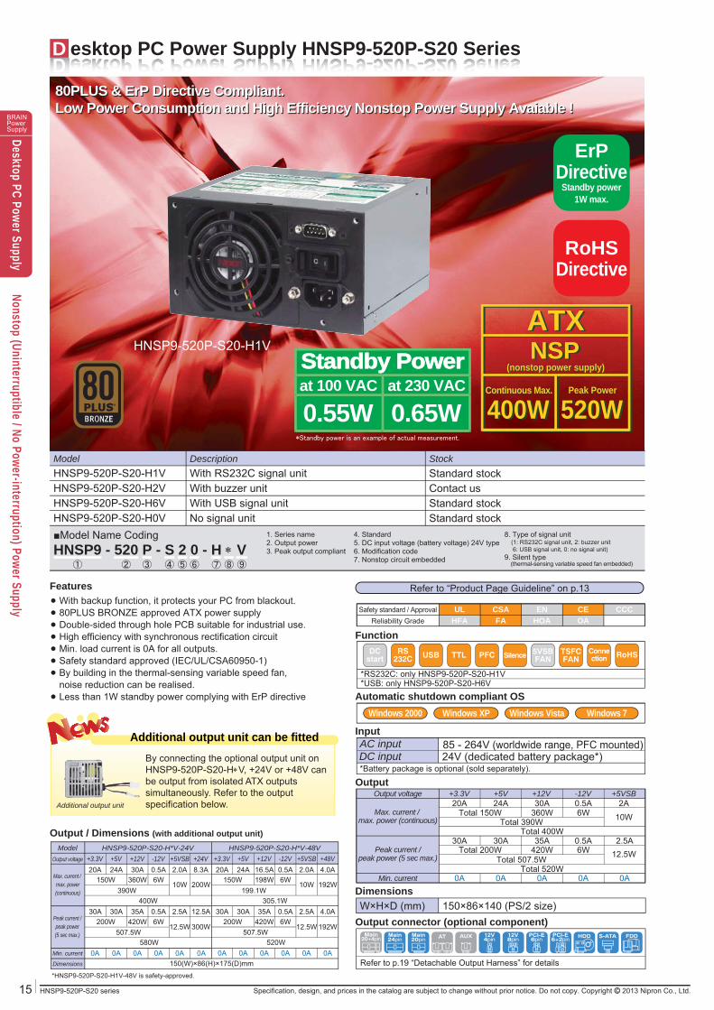
D esktop PC Power Supply HNSP9-520P-S20 Series
85 - 264V (worldwide range, PFC mounted)
●●●●●●●
●
Function
*USB: only HNSP9-520P-S20-H6V*RS232C: only HNSP9-520P-S20-H1V
RS232C USB PFC Silence 5VSB
FANTSFCFAN RoHSConne
ctionDCstart TTL
Model StockDescription
HNSP9-520P-S20-H6V Standard stockWith USB signal unitHNSP9-520P-S20-H0V Standard stockNo signal unit
HNSP9-520P-S20-H2V Contact usWith buzzer unitHNSP9-520P-S20-H1V Standard stockWith RS232C signal unit
1. Series name2. Output power3. Peak output compliant
4. Standard5. DC input voltage (battery voltage) 24V type6. Modification code7. Nonstop circuit embedded
8. Type of signal unit (1: RS232C signal unit, 2: buzzer unit 6: USB signal unit, 0: no signal unit)9. Silent type (thermal-sensing variable speed fan embedded)
■Model Name CodingHNSP9 - 520 P - S 2 0 - H V
① ② ④ ⑦ ⑨③ ⑤ ⑥ ⑧
HNSP9-520P-S20-H1V
DimensionsW×H×D (mm) 150×86×140 (PS/2 size)
Safety standard / Approval UL ENCSA CE CCCReliability Grade HFA HOAFA OA
ErPDirective
Standby power1W max.
Output connector (optional component)
OutputOutput voltage
Max. current / max. power (continuous)
Peak current /peak power (5 sec max.)
+3.3V20A
30A
+12V30A
360W
35A420W
Total 400W
Total 520W
+5V24A
Total 390W
30A
Total 507.5W
Total 150W
Total 200W
-12V0.5A6W
6W0.5A
+5VSB2A
10W
2.5A12.5W
InputAC inputDC input 24V (dedicated battery package*)*Battery package is optional (sold separately).
Refer to “Product Page Guideline” on p.13
Additional output unit can be fittedBy connecting the optional output unit on HNSP9-520P-S20-HV, +24V or +48V can be output from isolated ATX outputs simultaneously. Refer to the output specification below.Additional output unit
Output / Dimensions (with additional output unit)Model HNSP9-520P-S20-H*V-24V
Output voltage
Peak current /peak power(5 sec max.)
Max. current / max. power(continuous)
+3.3V20A
150W390W
400W
10W 200W360W 6W
24A 30A 0.5A 2.0A 8.3A
0A 0A 0A 0A 0A 0A
30A200W
507.5W580W
12.5W 300W420W 6W
30A 35A 0.5A 2.5A 12.5A
+5V +12V +24V-12V +5VSB
Min. current
Dimensions
HNSP9-520P-S20-H*V-48V+3.3V20A
150W199.1W
305.1W
10W 192W198W 6W
24A 16.5A 0.5A 2.0A 4.0A
0A 0A 0A 0A 0A 0A
30A200W
150(W)×86(H)×175(D)mm
507.5W520W
12.5W 192W420W 6W
30A 35A 0.5A 2.5A 4.0A
+5V +12V +48V-12V +5VSB
Standby PowerStandby Power
0.55Wat 100 VAC
0.65Wat 230 VAC
Automatic shutdown compliant OSWindows Vista Windows 7Windows XPWindows 2000
Main24pin
Main20pin
HDD FDDS-ATAAT AUXMain20+4pin
12V4pin
12V8pin
PCI-E6pin
PCI-E6+2pin
Refer to p.19 “Detachable Output Harness” for details*HNSP9-520P-S20-H1V-48V is safety-approved.
*Standby power is an example of actual measurement.
RoHSDirective
ATXNSPATXNSP
(nonstop power supply)(nonstop power supply)
400W400W 520W520WContinuous Max.Continuous Max. Peak PowerPeak Power
FeaturesWith backup function, it protects your PC from blackout.80PLUS BRONZE approved ATX power supplyDouble-sided through hole PCB suitable for industrial use.High efficiency with synchronous rectification circuitMin. load current is 0A for all outputs.Safety standard approved (IEC/UL/CSA60950-1)By building in the thermal-sensing variable speed fan,noise reduction can be realised.Less than 1W standby power complying with ErP directive
Min. current 0A 0A0A 0A 0A
80PLUS & ErP Directive Compliant.Low Power Consumption and High Efficiency Nonstop Power Supply Avaiable !80PLUS & ErP Directive Compliant.Low Power Consumption and High Efficiency Nonstop Power Supply Avaiable !
BRAINPowerSupplyDesktop PC Power Supply
Nonstop (Uninterruptible / No Power-interruption) Power Supply
HNSP9-520P-S20 seriesSpecification, design, and prices in the catalog are subject to change without prior notice. Do not copy. Copyright 2013 Nipron Co., Ltd. 16
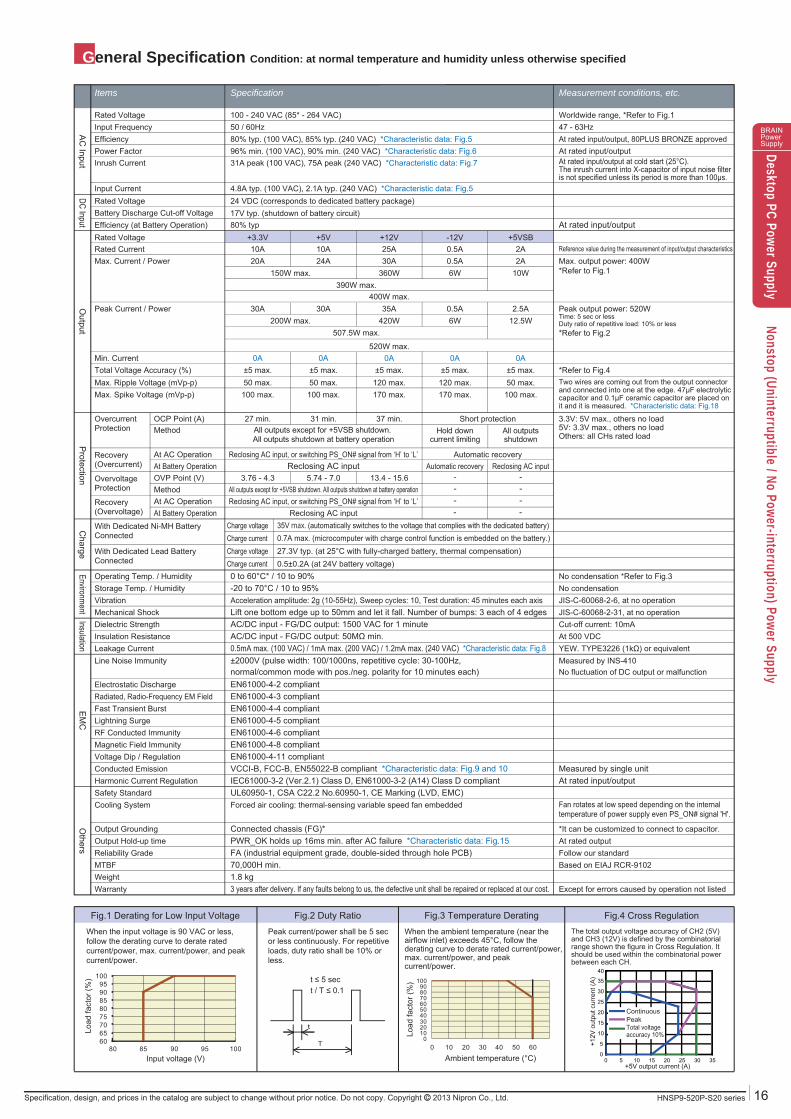
General Specification Condition: at normal temperature and humidity unless otherwise specified
Fan rotates at low speed depending on the internaltemperature of power supply even PS_ON# signal 'H'.
+5V output current (A)
+12V
out
put c
urre
nt (A
)t ≤ 5 sect / T ≤ 0.1
AC
InputO
utputP
rotectionEnvironm
entC
hargeInsulation
EM
CO
thersDC Input
SpecificationItems Measurement conditions, etc.
Rated Voltage 100 - 240 VAC (85* - 264 VAC) Worldwide range, *Refer to Fig.1
Rated Voltage +3.3V +5VSB-12V+12V+5V
390W max.400W max.
520W max.
507.5W max.
Max. Current / Power 20A 2A0.5A6W 10W
30A360W
24A Max. output power: 400W*Refer to Fig.1
OvercurrentProtection
Recovery(Overcurrent)
OCP Point (A) 27 min. Short protection37 min.31 min.
OvervoltageProtection
Recovery(Overvoltage)
OVP Point (V) 3.76 - 4.3 - -Automatic recovery Reclosing AC input
13.4 - 15.65.74 - 7.0Reclosing AC input
Reclosing AC input
At AC Operation
At AC Operation
At Battery Operation
At Battery Operation
Automatic recoveryReclosing AC input, or switching PS_ON# signal from ‘H’ to ‘L’
----
Reclosing AC input, or switching PS_ON# signal from ‘H’ to ‘L’
Total Voltage Accuracy (%) ±5 max. ±5 max.±5 max.±5 max.±5 max.
Max. Spike Voltage (mVp-p) 100 max. 100 max.170 max.170 max.100 max.Two wires are coming out from the output connectorand connected into one at the edge. 47μF electrolyticcapacitor and 0.1μF ceramic capacitor are placed onit and it is measured. *Characteristic data: Fig.18
Max. Ripple Voltage (mVp-p) 50 max. 50 max.120 max.120 max.50 max.
Peak Current / Power 30A 2.5A0.5A35A30A Peak output power: 520WTime: 5 sec or lessDuty ratio of repetitive load: 10% or less*Refer to Fig.2
Charge voltage 35V max. (automatically switches to the voltage that complies with the dedicated battery)
Charge voltage 27.3V typ. (at 25°C with fully-charged battery, thermal compensation)Charge current 0.7A max. (microcomputer with charge control function is embedded on the battery.)
Charge current 0.5±0.2A (at 24V battery voltage)
150W max.
200W max. 420W 6W 12.5W
Rated Current 10A 2A0.5A25A10A
Method All outputsshutdown
Hold downcurrent limiting
All outputs except for +5VSB shutdown. All outputs shutdown at battery operation
All outputs except for +5VSB shutdown. All outputs shutdown at battery operationMethod --
Min. Current 0A 0A0A0A0A
Efficiency (at Battery Operation)Battery Discharge Cut-off Voltage
80% typ17V typ. (shutdown of battery circuit)
At rated input/output
Reference value during the measurement of input/output characteristics
Rated Voltage 24 VDC (corresponds to dedicated battery package)
Operating Temp. / Humidity
With Dedicated Ni-MH BatteryConnected
With Dedicated Lead BatteryConnected
0 to 60°C* / 10 to 90% No condensation *Refer to Fig.3
Line Noise Immunity ±2000V (pulse width: 100/1000ns, repetitive cycle: 30-100Hz,normal/common mode with pos./neg. polarity for 10 minutes each)
Measured by INS-410 No fluctuation of DC output or malfunction
Warranty 3 years after delivery. If any faults belong to us, the defective unit shall be repaired or replaced at our cost. Except for errors caused by operation not listedWeight 1.8 kgMTBF 70,000H min. Based on EIAJ RCR-9102Reliability Grade FA (industrial equipment grade, double-sided through hole PCB) Follow our standardOutput Hold-up time PWR_OK holds up 16ms min. after AC failure *Characteristic data: Fig.15 At rated output
*It can be customized to connect to capacitor.Output Grounding Connected chassis (FG)*
Cooling System Forced air cooling: thermal-sensing variable speed fan embedded
Harmonic Current Regulation IEC61000-3-2 (Ver.2.1) Class D, EN61000-3-2 (A14) Class D compliant At rated input/outputConducted Emission VCCI-B, FCC-B, EN55022-B compliant *Characteristic data: Fig.9 and 10 Measured by single unit
Electrostatic Discharge EN61000-4-2 compliant
Voltage Dip / Regulation EN61000-4-11 compliantMagnetic Field Immunity EN61000-4-8 compliantRF Conducted Immunity EN61000-4-6 compliantLightning Surge EN61000-4-5 compliantFast Transient Burst EN61000-4-4 compliantRadiated, Radio-Frequency EM Field EN61000-4-3 compliant
Safety Standard UL60950-1, CSA C22.2 No.60950-1, CE Marking (LVD, EMC)
Leakage Current 0.5mA max. (100 VAC) / 1mA max. (200 VAC) / 1.2mA max. (240 VAC) *Characteristic data: Fig.8 YEW. TYPE3226 (1kΩ) or equivalentAt 500 VDCCut-off current: 10mA
Insulation Resistance AC/DC input - FG/DC output: 50MΩ min.Dielectric Strength AC/DC input - FG/DC output: 1500 VAC for 1 minuteMechanical Shock Lift one bottom edge up to 50mm and let it fall. Number of bumps: 3 each of 4 edges JIS-C-60068-2-31, at no operationVibration Acceleration amplitude: 2g (10-55Hz), Sweep cycles: 10, Test duration: 45 minutes each axis JIS-C-60068-2-6, at no operationStorage Temp. / Humidity -20 to 70°C / 10 to 95% No condensation
Input Current 4.8A typ. (100 VAC), 2.1A typ. (240 VAC) *Characteristic data: Fig.5
Inrush Current 31A peak (100 VAC), 75A peak (240 VAC) *Characteristic data: Fig.7 At rated input/output at cold start (25°C). The inrush current into X-capacitor of input noise filter is not specified unless its period is more than 100μs.
Power Factor 96% min. (100 VAC), 90% min. (240 VAC) *Characteristic data: Fig.6Efficiency 80% typ. (100 VAC), 85% typ. (240 VAC) *Characteristic data: Fig.5 At rated input/output, 80PLUS BRONZE approved
At rated input/output
Input Frequency 50 / 60Hz 47 - 63Hz
When the input voltage is 90 VAC or less, follow the derating curve to derate rated current/power, max. current/power, and peak current/power.
Peak current/power shall be 5 sec or less continuously. For repetitive loads, duty ratio shall be 10% or less.
Fig.1 Derating for Low Input Voltage Fig.3 Temperature DeratingFig.2 Duty Ratio
t
T0
102030405060708090
100
0 10 20 30 40 50 60
Load
fact
or (%
)
6065707580859095
100
80 85 90 95 100Input voltage (V)
Load
fact
or (%
)
0
5
10
15
20
25
30
35
40
0 5 10 15 20 25 30 35
Total voltageaccuracy 10%
*Refer to Fig.4
3.3V: 5V max., others no load5V: 3.3V max., others no loadOthers: all CHs rated load
Standby Power
When the ambient temperature (near the airflow inlet) exceeds 45°C, follow the derating curve to derate rated current/power, max. current/power, and peak current/power.
Ambient temperature (°C)
Fig.4 Cross RegulationThe total output voltage accuracy of CH2 (5V) and CH3 (12V) is defined by the combinatorial range shown the figure in Cross Regulation. It should be used within the combinatorial power between each CH.
ContinuousPeak
17 HNSP9-520P-S20 series Specification, design, and prices in the catalog are subject to change without prior notice. Do not copy. Copyright 2013 Nipron Co., Ltd.
BRAINPowerSupplyDesktop PC Power Supply
Nonstop (Uninterruptible / No Power-interruption) Power Supply
Signal Input / Output Specification Condition: at normal temperature and humidity unless otherwise specified
//
Internal Structure Additional Output Unit
Items Specification Note
Input SignalO
utput Signal
Output ON / OFF Control Signal(PS_ON#)
Battery Shutdown Signalfor TTL (SHUT DOWN_T)
Fan Control Signal(FAN_C)
Blackout Detection Signalfor TTL (AC FAIL_T)
Low Battery Voltage Signalfor TTL (BATT LOW_T)
Low Battery Voltage Signalfor RS232C (BATT LOW_R)
Low Battery Voltage Signalfor USB (BATT LOW_U)
Blackout Detection Signalfor RS232C (AC FAIL_R)
Buzzer Noise
Blackout Detection Signalfor USB (AC FAIL_U)
Battery Shutdown Signalfor RS232C (SHUT DOWN_R)
+3.3V, +5V, +12V, and -12V outputs shutdown with ‘H’ or ‘OPEN’ input.(During the backup operation, battery connection is shut off with ‘H’ or ‘OPEN’ input.)
The pin 22 of MAIN1 connector,the pin 6 of SIG connector
+3.3V SENSE The input terminal to detect the voltage of +3.3V output; by connecting to the load terminal,only the line drop of the + side of the output cable is compensated.
The pin 2 of MAIN1 connector
Normal Output Signal (PWR_OK) ‘H’signal is delivered at normal output (detection delay time: 100 - 500ms). The pin 21 of MAIN1 connector
The pin 5 of SIG connector
The pin 2 of SIG connector
Apply to only HNSP9-520P-S20-H1VThe pin 4 of front panel RS232C connector
The pin 4 of SIG connector
Fan Monitor Signal (FAN_M) Two cycle pulses per one rotation of the fan motor are delivered (open collector output).Duty ratio of the pulse shall be 0.5 typ. (Interval between the signals becomes longer at low speed and shorter at high speed.)The signal remains 'L' or 'OPEN' when the fan stops caused by any failure or malfunction.
One rotation
Battery connection is shut down with ‘L’ input (60ms min. input).(available only during the backup operation)
The signal goes ‘OPEN' at low AC input voltage and blackout detection (open collector output).(detection voltage: 75 VAC typ., detection delay time: 16 - 40ms after AC input failure at rated input/output)
‘Negative (-9V typ.)’ is delivered at low AC input voltage and blackout detection.(detection voltage: 75 VAC typ., detection delay time: 16 - 40ms after AC input failure at rated input/output)
'Negative (-9V typ.)' is delivered when the battery terminal voltage decreases to 19V typ.('positive (+9V typ.)' is delivered when the battery package is not connected.)
The equivalent data signal of BATT LOW_R 'negative' is delivered when the battery terminal voltage decreases to 19V typ.(The equivalent data signal of BATT LOW_R 'positive' is delivered when the battery package is not connected.)
Buzzer noise is delivered at blackout (the volume can be adjusted).Note: The buzzer may go off for a few seconds when AC input is turned on or interrupted.
The equivalent data signal of AC FAIL_R 'negative' is delivered at low AC input voltage and blackout detection.(detection voltage: 75 VAC typ., detection delay time: 16 - 40ms after AC input failure at rated input/output)
The signal goes ‘OPEN’ when the battery terminal voltage decreases to 19V typ.(open collector output). ‘L’ is delivered when the battery package is not connected.
Battery connection is shut down with ‘positive (+2.4V min.)’ input (60ms min. input). (available only during the backup operation)
The control terminal of fan motor; the fan motor is forcibly rotated at full speed at ‘L’ input.
Apply to only HNSP9-520P-S20-H1VThe pin 8 of front panel RS232C connector
The pin 3 of SIG connector
The pin 1 of SIG connector
Apply to only HNSP9-520P-S20-H1VThe pin 1 of front panel RS232C connector
Apply to only HNSP9-520P-S20-H6VFront panel USB connector
Apply to only HNSP9-520P-S20-H2V
Apply to only HNSP9-520P-S20-H6VFront panel USB connector
Signal Circuit
Output Signal C
ircuitInput Signal C
ircuit
(PS_ON#)
(PWR_OK)
(‘L’≤0.8V, 2.0V≤‘H’)
Power supply side +5VSB
Signal input terminal
1mA max.5.25V max.
4.7kΩ typ.
(‘L’≤0.4V, 2.4V≤‘H’)
Power supply side +5VSB
Signal input terminal
1mA max.5.25V max.
4.7kΩ typ.
(‘L’<0.4V)
Power supply side+5V(CH2)
Signal output terminal
5mA max.5.25V max.
1kΩ typ.
(‘L’<0.4V)
Power supply side
Signal output terminal
5mA max.5.25V max.
ADM232AARN (Analog Devices)or equivalent
Inner logic
Power supply side
RS232C output
ADM232AARN (Analog Devices)or equivalent
Inner logic
Power supply side
RS232C input
USB1.1 standard compliant (B type connector) *Dedicated driver software needs to be installed to the PC (Existing UPS services or other softwares that use RS232C signal can be used with USB signal).
(AC FAIL_T), (FAN M), (BATT LOW_T) (AC FAIL_R), (BATT LOW_R) (AC FAIL_U), (BATT LOW_U)
(SHUT DOWN_T)(SHUT DOWN_R)
Apply to only HNSP9-520P-S20-H1V
Apply to only HNSP9-520P-S20-H1V Apply to only HNSP9-520P-S20-H6V
Additionaloutput unit
18HNSP9-520P-S20 seriesSpecification, design, and prices in the catalog are subject to change without prior notice. Do not copy. Copyright 2013 Nipron Co., Ltd.
BRAINPowerSupplyDesktop PC Power Supply
Nonstop (Uninterruptible / No Power-interruption) Power Supply
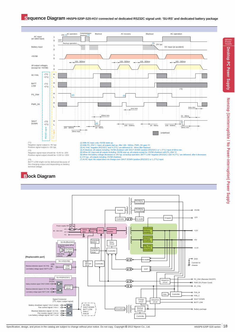
Sequence Diagram HNSP9-520P-S20-H1V connected w/ dedicated RS232C signal unit: ‘SU-RS’ and dedicated battery package
AC input(at rated input)
PS_ON#
+5VSB
All output voltages(except for +5VSB)
PWR_OK
10
10
10
1
0
H
L
H
L
H
L
H
L
H
L
Battery input
AC FAIL
SHUTDOWN
BATTLOW
ON
OFF
19V typ.////
100 - 500ms 100 - 500ms100 - 500ms 100 - 500ms
16ms max.
100 - 500ms100 - 500ms100 - 500ms 16ms min.
60ms min.
1ms min. 1ms min.
16 - 40ms
16 - 40ms
16 - 40ms
Undefined
-(*1)+(*1)
-(*1)+(*1)
-(*2)+(*1)
TTL
sign
al
RS23
2C s
igna
l
(*1)Negative signal output is -9V typ.Positive signal output is +9V typ.(*2)Negative signal input should be +0.4V to -20V.Positive signal output should be +2.8V to +20V.
(*3)BATT LOW might not be delivered because of the charging output and depending on bettery terminal voltage
(*3)
PFCSynchronousrectifying/smoothing
Rectifying/smoothing
+5V
+3.3V
+5VSB
FAN_M
-12V
Rectifying/smoothing
FAN_C
GND
Connect tochassis
AC L
AC N
FG
Noisefilter
PS_ON# (Remote ON/OFF)
PWR OK (Power Good)
AC_FAIL
Rectifyingcircuit
Resonance inverter
Inverter
+12V
OVP
Chargecircuit
Sequencecircuit
ControllerFAN
SHUT DOWN
BATT LOW
Battery package
DropperError amplifier
Drivecircuit
Synchronousrectifying/smoothing
Mag. amp.rectifying/smoothing
Error amplifier
Backupinverter
Controller
Sequencecircuit
Smoothing
Controller
Block Diagram
SU-RS(RS232C)
Signal Connector(TTL input / output signal)
Blackout detection signal / AC FAILFan monitor signal / FAN M
Low battery voltage signal / BATT LOW
Fan control signal / FAN CBattery shutdown signal / SHUT DOWN
RS232Cdriver
AC FAILSHUT DOWNBATT LOWFAN CFAN M
1
51
42
3
D-sub(9-Pin)
SU-US2(USB)
USB(B) USB
driver
[Replaceable part]
Blackout detection signal / AC FAIL
Low battery voltage signal / BATT LOW
Battery shutdown signal / SHUT DOWN 4
Blackout detection signal / AC FAIL 8
Low battery voltage signal / BATT LOW
Oscillator(2.8kHz)
Adjusting volume
A buzzer goes off atblackout
SU-BU(buzzer)
(1) With AC input, only +5VSB starts up. (2) With PS_ON# ‘L’ input, all outputs start up. After 100 - 500ms, PWR_OK goes ‘H'.(3) AC FAIL ‘negative (RS232C)’ and ‘H (TTL)’ are delivered 16 - 40ms after blackout.(4) At blackout, all outputs including +5VSB shutdown with SHUT DOWN ‘positive (RS232C)’ or ‘L (TTL)’ input of 60ms min.(5) When AC input and all outputs including +5VSB start up, all outputs except for +5VSB shutdown with PS_ON# ‘H'.(6) When the battery voltage decreases to 19V typ. at backup operation, BATT LOW ‘negative (RS232C)’ and ‘H (TTL)’ are delivered; after it decreases to 17V typ., all outputs including +5VSB shutdown. (7) At AC input, the output does not change even SHUT DOWN ‘positive (RS232C)’ or ‘L (TTL)' input.
(4)
(1)
(2)
(3)
(5)
(6)
(7)
AC operation Instantaneousblackout
Blackout AC recovery
Backup operation
AC operationBlackout
DC input (at accident)
Power supply SW
85 - 264 VAC
Temperaturedetection
Overheatprotectioncircuit
Controller
Controller
Inputdetection circuit

Outline Drawing
WH-M2022-300
WH-M2022-500
300±10 20-pin
500±10 20-pin
WH-VG208-500
WH-V0408-500
WH-M2422-500 500±15 24-pin
WH-S0310-500
WH-S0610-500-01
WH-S0610-500
peripheral (HD)
FD
S-ATA
500±15 12V 4-pin
WH-PP610-850
WH-PS610-850
WH-PS710-850
500±1512V 4-pin PCI-E 6-pin
500±10PCI-E 6-pin
150±15 150±15550±15
150±15 150±15550±15
150±15 150±15550±15
850±15
SIG-1500±15
SIG-2500±15
SIG-3500±15
WH-V0808-500 500±15 12V 8-pin
WH-VV208-500-02
WH-G0808-500
WH-GG208-500
WH-VG208-500-02
12V 8-pin 500±10
12V 8-pin
12V 8-pin
MAIN1
MAIN2
FUNCTION+3.3V
+3.3V SE+12V+5V+5VCOMCOMCOMCOM-12V
+5VSB+3.3V+3.3V+12V+5V+5VCOMCOMCOMCOM
PWR_OKPS_ON
+5V+3.3V
MAX CURRENT6 A
-6 A6 A6 A6 A6 A6 A6 A0.5A4 A6 A6 A6 A6 A6 A6 A6 A6 A6 A
5 mA1 mA6 A6 A
PIN No.1234567891011121314151617181920212212
FUNCTIONCOMCOMCOMCOM+12V+12V+12V+12V+3.3V+5VCOMCOM+12V+3.3V+5VCOMCOM+12V
AC_FAILSHUT DOWN_TBATT LOW_TFAN_CFAN_MPS_ONCOM
+3.3V SENC
+5VSB
MAX CURRENT6 A6 A6 A6 A6 A6 A6 A6 A6 A6 A6 A6 A6 A6 A6 A6 A6 A6 A
5 mA1 mA5 mA
-5 mA1 mA2 A
--
2 A
PIN No.12345678123456789
10123456789
10
12V1-2
HD
SIGNipron
12V2
12V1
MAIN2
MAIN1
SIG
HD
BATT
POWER SWITCH
150±1
138
114
IEC320
64
43
6
16
FAN BLOW52
72
6
140±
1
86±1
49
74
AC INLET
26
40
6
max
.8
20 110
146
6
Optional connectorprotection seal Optional output
Mounting hole for optional unit
HD
BATT
MAIN1 / MAIN2
12V1 / 12V2
SIG
CP-01322130/CP-01302130(CviLux) or Equivalent
CP-01308130(CviLux) or Equivalent
CP-01310130(CviLux) or Equivalent
S10B-PADSS-1(JST) or Equivalent
B03P-VL(JST) or Equivalent
*The screw depth of penetration into PSU is 12mm max.*Dimensional tolerance shall be ±0.5 unless otherwise specified.
12V2
12V1
MAIN2
MAIN1
SIG
HD
BATT
MAI
N
SIG
HD
12V
12V
500±10PCI-E 6+2-pin
500±10PCI-E 6-pinPCI-E 6+2-pin
MAINMain power cable
12V12V power cable
HDHD power cable
SIGSIG cable
Model Length and Type of Connector Output Port AllocationDetachable Output Harness
MAI
NM
AIN
MA
IN12
V12
V12
V12
V12
V12
V12
VH
DH
DH
DSI
GSI
GSI
G
MAIN 12V HD SIG1 model 1 model1 model2 models
Acceptable cable(s)
■Installation directionThe unit can be installed in any directions.
Contact us if you have a problem with interference with chassis as flat panel (metal plate type) is available.
Rating & Caution label
LabelDescription
Production No.Others
Mounting hole
Mounting hole
Spacer
SEAL
INGST
ICKER
SEALINGSTICKER
How to process the mounting holes(Recommended)
Optional Components Sold Separately
.
BRAINPowerSupplyDesktop PC Power Supply
Nonstop (Uninterruptible / No Power-interruption) Power Supply
19 HNSP9-520P-S20 series Specification, design, and prices in the catalog are subject to change without prior notice. Do not copy. Copyright 2013 Nipron Co., Ltd.

BRAINPowerSupplyDesktop PC Power Supply
Nonstop (Uninterruptible / No Power-interruption) Power Supply
20HNSP9-520P-S20 seriesSpecification, design, and prices in the catalog are subject to change without prior notice. Do not copy. Copyright 2013 Nipron Co., Ltd.
BRAINPowerSupply
Optional Components Sold Separately
*The backup time is a reference value at initial use; it is not a guaranteed value.
P.402 BS11A-P24/2.3L 5-inch bay fixed type(W×D×H=146×190×37mm)
P.409
P.413
BS10A-H24/2.0L
P.405 BS12A-P24/5.0L
P.404 RBS02A-P24/2.3L
BS22A-H24/2.0L
ModelACC2637WH2820WH2747WH2892-02WH2884WH2812
DescriptionAutomatic startup unit20-pin extension harness (600mm) 20-pin extension harness (450mm) 20-pin extension harness (200mm) Battery extension cable (450mm) PCI-E 6-pin connector conversion harness
ModelWH5105WH5105-02WH5055ACC5046ACC5077WH5073
Description12V 4-pin connector conversion harness (80mm) 12V 4-pin connector conversion harness (320mm) AT connector conversion harnessHarness with PS_ON switchPS_ON terminal short connectorPS_ON terminal short 20-pin harness
Other Optional Components
ACC2734AC power cordretention clamp
It prevents the slipping of AC power cord (WH2753, WH2753-02) and operationalMistakes of power switch. *In some cases, the clamp (ACC2734) might not be possible mounted to a commercial AC power cord.
SU-RS RS232C signal unitAutomatic shutdown is possible with RS232C.(standard equipment for HNSP9-520P-S20-H1V)
SU-US2 USB signal unit
SU-BU Buzzer unitBuzzer noise is delivered at blackout (the volume can be adjusted). (standard equipment for HNSP9-520P-S20-H2V)
WH2753
WH2967
125 VAC 12A[PSE]
USB communicationcable
USB communication cableThe cable can be used with power supplies equipped with SU-US2 (USB signal unit). [RoHS]
WH2601-02 RS232C communicationcable
WH2753-02 AC power cord
AC power cord
Automatic shutdownsoftware Dedicated to Windows 2000 / XP / Vista / 7
*Free software "NSP Pro 2" available at our web-site*The UPS service of Windows 2000 and XP available
SoftwarePicture Model Type Description
Picture Model Type Description
Picture Model Type Description
Cable
Tim
e (m
inut
e)
200150100 50 0
10
20
Load (W)
200150100 50 0
10
20
Load (W)
Tim
e (m
inut
e)
Battery packagePage Picture Model Type Shape (size) Backup Time
Load (W) 350250 300150 200 100 0
10
20
30
Tim
e (m
inut
e)
Tim
e (m
inut
e)
Load (W) 300250200 150 100 0
10
20
Tim
e (m
inut
e)
Load (W) 300250200 150 100 0
10
20
Lead
Ni-MH
Ni-MH
Lead
Lead
5-inch bay fixed type(W×D×H=146×200×38mm)
5-inch bay fixed type(W×D×H=146×210×41mm)
5-inch bay 2-unit fixed type(W×D×H=146×190×74.9mm)
5-inch bay fixed, removable type(W×D×H=146×245×42mm)
125 VAC 12A (tracking resistance type) [PSE]
Parts / Unit
NSP Pro 2
*reference image
Dedicated to Windows 2000 / XP / Vista / 7. The cable can be used with power supplies equipped with SU-RS (RS232C signal unit). [RoHS]
Automatic shutdown is possible with USB.(standard equipment for HNSP9-520P-S20-H6V)
BRAINPowerSupplyDesktop PC Power Supply
Nonstop (Uninterruptible / No Power-interruption) Power Supply
21 HNSP9-520P-S20 series Specification, design, and prices in the catalog are subject to change without prior notice. Do not copy. Copyright 2013 Nipron Co., Ltd.
Characteristics Data HNSP9-520P-S20-H1V (Examples of actual measurement)
0102030405060708090
100
0 100 200 300 400 5000
1
2
3
4
5
0102030405060708090
100
0 100 200 300 400 5000
100
200
300
400
500
VCCI Class BVCCI Class B VCCI Class BVCCI Class B
100 VAC240 VAC
100 VAC240 VAC
Output
Measuring point: L-FG
Measuring point: N-FG
Measuring point: L-FG
Measuring point: N-FG
100 VAC 0.18mA 0.17mA
200 VAC 0.30mA 0.29mA
240 VAC 0.35mA 0.35mA
Rated load Min. load
Input: 100 VACLoad: RatedTime axis:10ms/DIV
Input: 100 VACLoad: RatedTime axis:10ms/DIV
Input: 100 VACLoad: RatedMode: Peak
Input: 230 VACLoad: RatedMode: Peak
+12V
-12V
100 VAC
+5VSB
+5V
+3.3V
PS_ON#PWR_OK
Efficiency
Input current
Power factor
Input VA
Effi
cien
cy [%
]
Output power [W]
Inpu
t cur
rent
[A]
Pow
er fa
ctor
[%]
Output power [W]
Inpu
t VA
[VA
]
Inrush current: 21.6A (at 100 VAC)
Inrush current: 61.0A (at 240 VAC)
Input: 100 / 200 / 240 VACLoad: Rated and min. loadMeasurement conditions: IEC60950 compliant
● Fig.6 Power Factor / Input VA vs. Output Power● Fig.5 Efficiency / Input Current vs. Output Power
● Fig.7 Inrush Current
● Fig.10 Conducted Emission at 230 VAC● Fig.9 Conducted Emission at 100 VAC
● Fig.8 Leakage Current
● Fig.12 Falling Characteristics at 100 VAC when REMOTE goes Off ● Fig.11 Rising Characteristics at 100 VAC
BRAINPowerSupplyDesktop PC Power Supply
Nonstop (Uninterruptible / No Power-interruption) Power Supply
22HNSP9-520P-S20 seriesSpecification, design, and prices in the catalog are subject to change without prior notice. Do not copy. Copyright 2013 Nipron Co., Ltd.
Characteristics Data HNSP9-520P-S20-H1V (Examples of actual measurement)
020406080
100120140160180
0 100 200 300 400 500
0123456789
1011121314
0 5 10 15 20 25 30 35 40 45
+3.3V+5V
+12V
3.311 V 3.311 V 3.308 V 3.308 V
85 VAC 100 VAC 240 VAC 264 VAC
3.303 V 3.303 V 3.298 V 3.298 V
5.072 V 5.073 V 5.072 V 5.072 V
5.009 V 5.009 V 5.009 V 5.009 V
12.028 V 12.027 V 12.015 V 12.014 V
11.982 V 11.982 V
3.311 V
132 VAC
3.303 V
5.073 V
5.010 V
12.026 V
11.980 V
3.308 V
176 VAC
3.299 V
5.073 V
5.008 V
12.014 V
11.978 V 11.976 V 11.976 V
Expected service life (yr)
VCCI Class B VCCI Class B
Expected service life (yr)
● Fig.19 Ambient Temperature vs. Expected Service Life
Input: 100 VACLoad: RatedOperating time: 24 consecutive hours
● Fig.20 Over Current Protection (V-I Characteristic)
Input: 240 VACLoad: RatedTime axis: 10ms/DIV
OutputOutput Rated loadMin. load
+12V output 0A 25A+5V output 0A 10A
+3.3V output 0A 10A
AC input voltage
+3.3V output (rated load)
+3.3V output (min. load)
+5V output (rated load)
+5V output (min. load)
+12V output (rated load)
+12V output (min. load)
PWR_OKOutput voltageAC FAIL
■ Electrolytic capacitors
Intake air temp. 20°C 30°C 40°C 45°C
approx. 48 approx. 24 approx. 12 approx. 8.6※ Lifetime shall be 15 years at longest due to deterioration of sealing plates.
■ Fan
Ambient temp. 20°C 30°C 40°C 45°C
approx. 13 approx. 13 approx. 13 approx. 11
Input: 240 VACLoad: RatedTime axis: 10ms/DIV
PWR_OK: the point that PWR_OK signal goes to “L”Output voltage: the point any output voltage decreases to 95% except +5VSBAC FAIL: the point that AC FAIL signal is delivered
Output power [W]
Hol
d-up
tim
e [m
s]
+12V output voltage(500mV/DIV)
+12V output current(25A/DIV)
+5V output voltage(500mV/DIV)
+3.3V output voltage(500mV/DIV)
+12V output voltage(20mV/DIV)
+5V output voltage(10mV/DIV)
+3.3V output voltage(20mV/DIV)
Output current [A]
Out
put v
olta
ge [V
]
Input: 100 VACLoad: RatedTime axis: 200μs/DIV
Input: 100 VACLoad: RatedTime axis: 2μs/DIV
Input: 100 VAC
● Fig.14 Falling Characteristics at 240 VAC when REMOTE goes Off ● Fig.13 Rising Characteristics at 240 VAC
● Fig.15 Output Hold-up Time vs. Output Power
● Fig.17 Output Voltage Regulation ● Fig.18 Ripple and Spike Voltage
● Fig.16 Dynamic Load Fluctuation Characteristics at 1kHz
+12V
-12V
240 VAC
+5VSB
+5V
+3.3V
PS_ON#PWR_OK