Embed Size (px)
Citation preview
Audi Vorsprung durch Technik
AudiService Training
43
9
Audi 2.0l TFSI fl exible fuel engine
All rights reserved.
Technical specifi cations subject to
change.
Copyright
AUDI AG
I/VK-35
AUDI AG
D-85045 Ingolstadt
Technical status 05/10
Printed in Germany
A10.5S00.57.20
Self-Study Programme 439
2
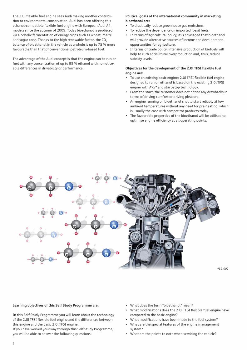
The 2.0l fl exible fuel engine sees Audi making another contribu-
tion to environmental conservation. Audi has been off ering this
ethanol-compatible fl exible fuel engine with European Audi A4
models since the autumn of 2009. Today bioethanol is produced
via alcoholic fermentation of energy crops such as wheat, maize
and sugar cane. Thanks to the high renewable factor, the CO2
balance of bioethanol in the vehicle as a whole is up to 75 % more
favourable than that of conventional petroleum-based fuel.
The advantage of the Audi concept is that the engine can be run on
fuel with any concentration of up to 85 % ethanol with no notice-
able diff erences in drivability or performance.
Political goals of the international community in marketing
bioethanol are:
• To drastically reduce greenhouse gas emissions.
• To reduce the dependency on imported fossil fuels.
• In terms of agricultural policy, it is envisaged that bioethanol
will provide alternative sources of income and development
opportunities for agriculture.
• In terms of trade policy, intensive production of biofuels will
help to curb agricultural overproduction and, thus, reduce
subsidy levels.
Objectives for the development of the 2.0l TFSI fl exible fuel
engine are:
• To use an existing basic engine; 2.0l TFSI fl exible fuel engine
designed to run on ethanol is based on the existing 2.0l TFSI
engine with AVS* and start-stop technology.
• From the start, the customer does not notice any drawbacks in
terms of driving comfort or driving pleasure.
• An engine running on bioethanol should start reliably at low
ambient temperatures without any need for pre-heating, which
is usually the case with competitor products today.
• The favourable properties of the bioethanol will be utilised to
optimise engine effi ciency at all operating points.
Learning objectives of this Self Study Programme are:
In this Self Study Programme you will learn about the technology
of the 2.0l TFSI fl exible fuel engine and the diff erences between
this engine and the basic 2.0l TFSI engine.
If you have worked your way through this Self Study Programme,
you will be able to answer the following questions:
• What does the term "bioethanol" mean?
• What modifi cations does the 2.0l TFSI fl exible fuel engine have
compared to the basic engine?
• What modifi cations have been made to the fuel system?
• What are the special features of the engine management
system?
• What are the points to note when servicing the vehicle?
439_002
3
!• The Self Study Programme explains the basics of the design and function of new models, new automotive
components or new technologies.
It is not a Repair Manual! Figures given are for explanatory purposes only and refer to the software version
valid at the time of preparation of the SSP.
For maintenance and repair work, always refer to the current technical literature. Terms shown in italics and
marked by an asterisk (*) are explained in the glossary at the back of this Self Study Programme.
Note
Reference
IntroductionBrief technical description _________________________________________________________________________________________________________________________________ 4
Specifi cations ________________________________________________________________________________________________________________________________________________ 5
BioethanolBasic information ___________________________________________________________________________________________________________________________________________ 6
Specifi cations for bioethanol ______________________________________________________________________________________________________________________________ 7
Comparison of fuel properties _____________________________________________________________________________________________________________________________ 7
Why E85, and not pure alcohol? ___________________________________________________________________________________________________________________________ 7
Production process __________________________________________________________________________________________________________________________________________ 9
Modifi cations to the basic engineDevelopment goals ________________________________________________________________________________________________________________________________________10
Cylinder liners ______________________________________________________________________________________________________________________________________________11
Cylinder head _______________________________________________________________________________________________________________________________________________11
Cranktrain ___________________________________________________________________________________________________________________________________________________12
Conrod _______________________________________________________________________________________________________________________________________________________12
Fuel systemIntroduction ________________________________________________________________________________________________________________________________________________13
Fuel quality sender G446 __________________________________________________________________________________________________________________________________16
Engine managementOverview of the Bosch MED 17.1 system ________________________________________________________________________________________________________________20
Cold starting ________________________________________________________________________________________________________________________________________________22
Cold starting with ethanol ________________________________________________________________________________________________________________________________23
Fuel ingress into the engine oil and fuel extraction from the engine oil _____________________________________________________________________________26
ServiceScope of maintenance _____________________________________________________________________________________________________________________________________28
Control and auxiliary drive ________________________________________________________________________________________________________________________________28
AnnexGlossary _____________________________________________________________________________________________________________________________________________________29
Test your knowledgeSummary ____________________________________________________________________________________________________________________________________________________31
Self Study Programmes ___________________________________________________________________________________________________________________________________31
Contents
4
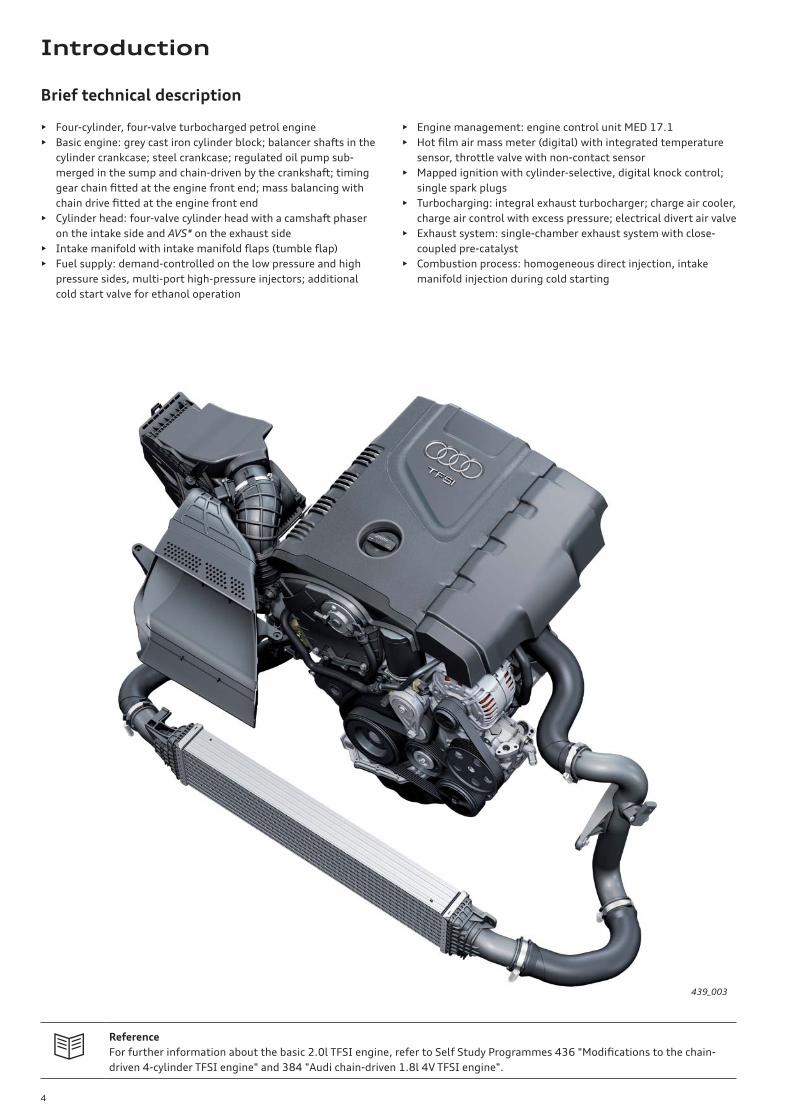
Brief technical description
• Four-cylinder, four-valve turbocharged petrol engine
• Basic engine: grey cast iron cylinder block; balancer shafts in the
cylinder crankcase; steel crankcase; regulated oil pump sub-
merged in the sump and chain-driven by the crankshaft; timing
gear chain fi tted at the engine front end; mass balancing with
chain drive fi tted at the engine front end
• Cylinder head: four-valve cylinder head with a camshaft phaser
on the intake side and AVS* on the exhaust side
• Intake manifold with intake manifold fl aps (tumble fl ap)
• Fuel supply: demand-controlled on the low pressure and high
pressure sides, multi-port high-pressure injectors; additional
cold start valve for ethanol operation
• Engine management: engine control unit MED 17.1
• Hot fi lm air mass meter (digital) with integrated temperature
sensor, throttle valve with non-contact sensor
• Mapped ignition with cylinder-selective, digital knock control;
single spark plugs
• Turbocharging: integral exhaust turbocharger; charge air cooler,
charge air control with excess pressure; electrical divert air valve
• Exhaust system: single-chamber exhaust system with close-
coupled pre-catalyst
• Combustion process: homogeneous direct injection, intake
manifold injection during cold starting
Reference
For further information about the basic 2.0l TFSI engine, refer to Self Study Programmes 436 "Modifi cations to the chain-
driven 4-cylinder TFSI engine" and 384 "Audi chain-driven 1.8l 4V TFSI engine".
439_003
Introduction
5
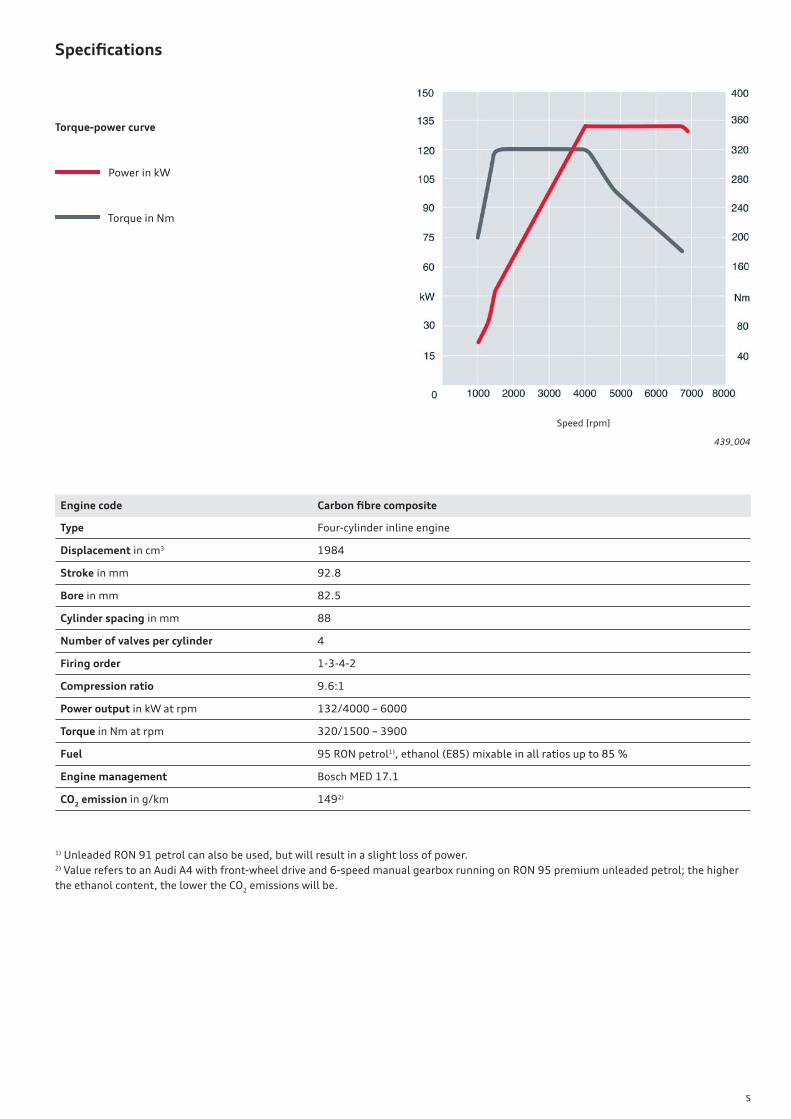
Specifi cations
Torque-power curve
Power in kW
Torque in Nm
1) Unleaded RON 91 petrol can also be used, but will result in a slight loss of power.2) Value refers to an Audi A4 with front-wheel drive and 6-speed manual gearbox running on RON 95 premium unleaded petrol; the higher
the ethanol content, the lower the CO2 emissions will be.
Engine code Carbon fi bre composite
Type Four-cylinder inline engine
Displacement in cm3 1984
Stroke in mm 92.8
Bore in mm 82.5
Cylinder spacing in mm 88
Number of valves per cylinder 4
Firing order 1-3-4-2
Compression ratio 9.6:1
Power output in kW at rpm 132/4000 – 6000
Torque in Nm at rpm 320/1500 – 3900
Fuel 95 RON petrol1), ethanol (E85) mixable in all ratios up to 85 %
Engine management Bosch MED 17.1
CO2 emission in g/km 1492)
439_004
Speed [rpm]
6
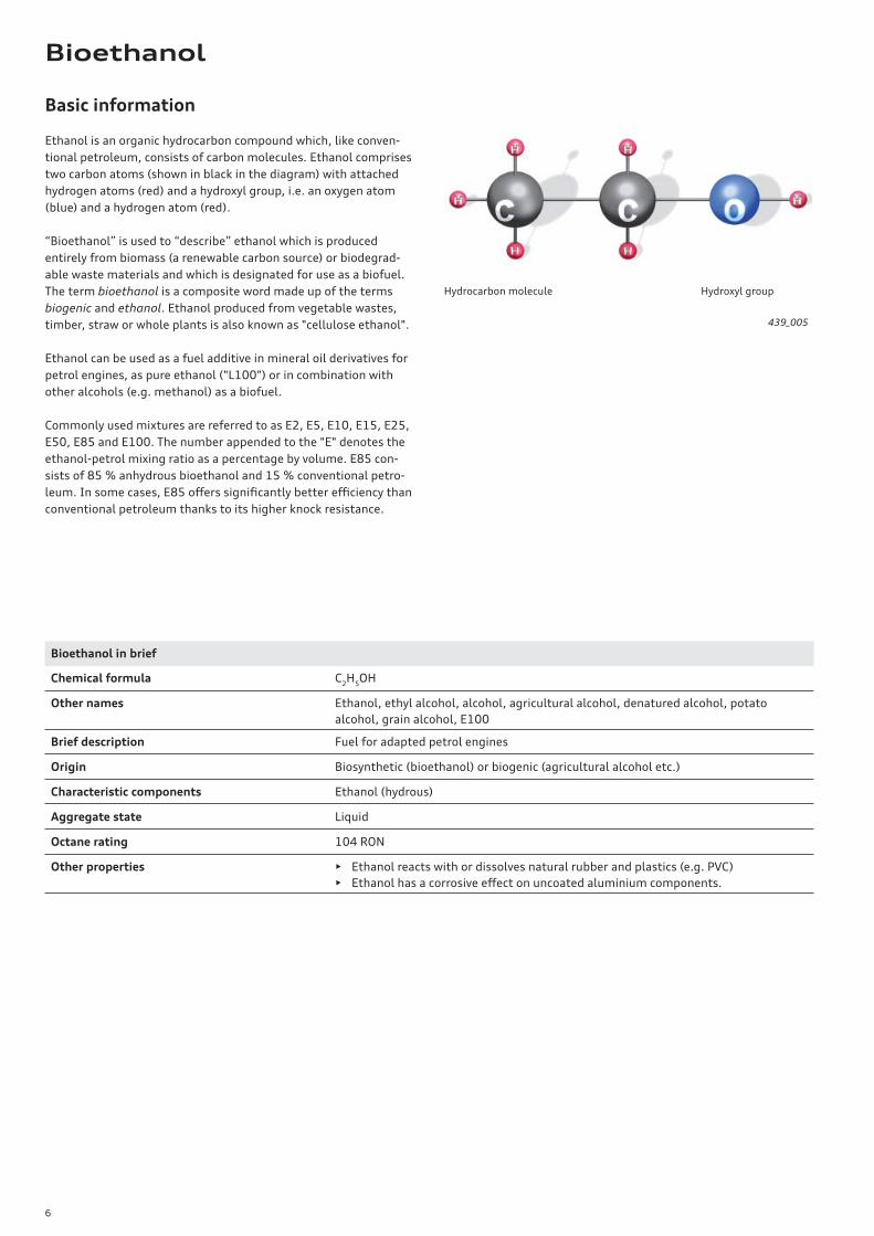
Basic information
Ethanol is an organic hydrocarbon compound which, like conven-
tional petroleum, consists of carbon molecules. Ethanol comprises
two carbon atoms (shown in black in the diagram) with attached
hydrogen atoms (red) and a hydroxyl group, i.e. an oxygen atom
(blue) and a hydrogen atom (red).
“Bioethanol” is used to “describe” ethanol which is produced
entirely from biomass (a renewable carbon source) or biodegrad-
able waste materials and which is designated for use as a biofuel.
The term bioethanol is a composite word made up of the terms
biogenic and ethanol. Ethanol produced from vegetable wastes,
timber, straw or whole plants is also known as "cellulose ethanol".
Ethanol can be used as a fuel additive in mineral oil derivatives for
petrol engines, as pure ethanol ("L100") or in combination with
other alcohols (e.g. methanol) as a biofuel.
Commonly used mixtures are referred to as E2, E5, E10, E15, E25,
E50, E85 and E100. The number appended to the "E" denotes the
ethanol-petrol mixing ratio as a percentage by volume. E85 con-
sists of 85 % anhydrous bioethanol and 15 % conventional petro-
leum. In some cases, E85 off ers signifi cantly better effi ciency than
conventional petroleum thanks to its higher knock resistance.
Bioethanol in brief
Chemical formula C2H
5OH
Other names Ethanol, ethyl alcohol, alcohol, agricultural alcohol, denatured alcohol, potato
alcohol, grain alcohol, E100
Brief description Fuel for adapted petrol engines
Origin Biosynthetic (bioethanol) or biogenic (agricultural alcohol etc.)
Characteristic components Ethanol (hydrous)
Aggregate state Liquid
Octane rating 104 RON
Other properties • Ethanol reacts with or dissolves natural rubber and plastics (e.g. PVC)
• Ethanol has a corrosive eff ect on uncoated aluminium components.
439_005
Hydrocarbon molecule Hydroxyl group
Bioethanol
7
!
Specifi cations for bioethanol
European standard DIN EN 228 allows up to 5 % ethanol to be
added to conventional petroleum (E5).
In Europe, fuels containing more than 5 % bioethanol must be
labelled appropriately.
Today, with few exceptions, nearly all modern Audi petrol engines
will run on E10 fuels.
Vehicles with fi rst-generation FSI* naturally aspirated engines are
not suitable for E10 fuel:
• A2 1.6l FSI, up to model year 2006
• A3 1.6l FSI, up to model year 2004
• A3 2.0l FSI, up to model year 2004
• A4 2.0l FSI, up to model year 2004
Comparison of fuel properties
Why E85, and not pure alcohol?
Due to the fact that ethanol has a fi xed boiling point (78 °C), an
ignitable mixture cannot form inside the cold engine. This is why
the ethanol is mixed with 15 % fuel.
E = ethanol, 85 = 85 % ethanol and 15 % petroleum.
There is no reason why pure ethanol should not be used in vehicles
which do not cool down completely or have an engine heater.
As a fuel, bioethanol off ers the following advantages:
• High octane rating (110 octane*)
• Contains no sulphur
• Contains no aromatic compounds
• High oxygen content
Premium unleaded petrol to DIN EN 228 E85 (better than DIN 51625-10.2007)
Density at 15 °C in kg/m3 720 – 775 780 – 788
Calorifi c value in MJ/litre 31.0 22.7
RON min. 95 min. 103 (depending on summer fuel/winter
fuel specifi cations)
MON min. 85 min. 90 (depending on summer fuel/winter
fuel specifi cations)
Enthalpy of vaporisation* in kJ/kg 440 840
Higher alcohols C3 – C5 in % by vol. not specifi ed 1.8
Water in % by vol. not specifi ed 0.3
Acid as AcOH in mg/litre not specifi ed 40
Oxygen content in % by vol. max. 2.7 max. 32 (in the case of E90)
Sulphur content in ppm max. 50 max. 8
Note
Audi A4 fi tted with an auxiliary heater (petrol-driven 8E9 models from model years 2000 – 2008 must be fi lled with super
plus unleaded petrol if the auxiliary heater is in operation). No conversion is possible.
8
CO2 reduction
Until now, reductions in CO2 emissions have principally been
achieved by the improvement of vehicles and engines. Today
bioethanol is produced via alcoholic fermentation of energy crops
such as wheat, maize and sugar cane. Due to the high regenerative
component, the CO2 balance of bioethanol within the overall
vehicle is up to 75 % better than that of conventional, petroleum-
based fuels.
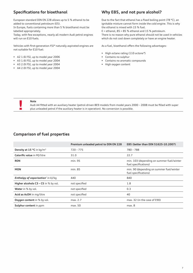
Production
Basically, a distinction is made between fi rst and second genera-
tion biofuels. First-generation biofuels are produced either from oil
or sugar-bearing plants which are in competition with food produc-
tion. The oil-bearing plants are processed into diesel fuels by
pressing and esterifi cation and the sugar-bearing plants are
converted to ethyl alcohol by fermentation.
Second-generation biofuels are obtained from organic wastes such
as straw, wood scraps, agricultural waste products, old timber,
sawmill by-products and inferior-grade forest timber.
In addition, use is made of fast-growing plants and timber varie-
ties which can also be grown in fi elds previously set aside. Second-
generation biofuels are fuels which have the capacity to improve
the overall CO2 balance.
This is not the case with fi rst-generation biofuels because large
quanties of fossil fuels are needed to produce them.
In accordance with a resolution passed by the European Parlia-
ment, new second-generation production processes will be imple-
mented in future so that bioethanol can be manufactured in large
volumes and more cost-eff ectively without producing high CO2
emissions.
From 2017 onwards, new production installations have to show a
reduction potential of at least 60 %. Existing installations must
verifi ably achieve 50 %.
Ethanol manufactured via the fi rst-generation production process
are already able to meet this requirement. This target can be met
by making more eff ective use of, for example, sugar beet, which
has a high energy yield (see diagram).
Conclusion: fi rst-generation ethanol, too, has the potential for
high CO2 reduction.
The use of regenerative fuels can potentially lead to signifi cant
savings taking the overall process into account. The plants convert
atmospheric CO2 to biomass during their growth phase. This
renewable energy can be subtracted from the automobile's emis-
sions.
439_006
CO
2 r
ed
uct
ion
po
ten
tia
l [%
]
Foodstuff s
1st generation 2nd generation
Waste materials, cellulose
New installations as of 2017
Existing installations
Current installations
Ethanol Biodiesel Hydrogenated
vegetable oil
Biogas 2nd generation
ethanol
BTL fuel*
State of the art
CO2-optimised
9
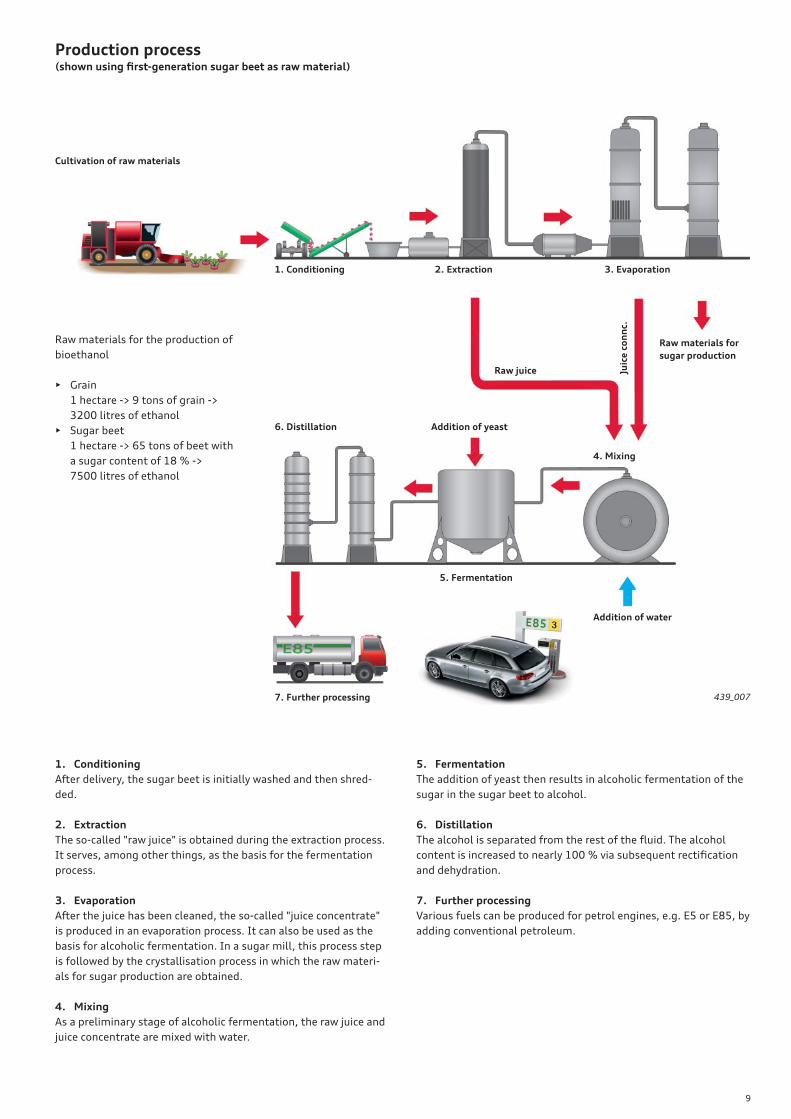
Production process(shown using fi rst-generation sugar beet as raw material)
Cultivation of raw materials
1. Conditioning
6. Distillation
7. Further processing
Addition of yeast
4. Mixing
Addition of water
5. Fermentation
2. Extraction 3. Evaporation
Raw materials for
sugar production
Raw juice Juic
e c
on
nc.
Raw materials for the production of
bioethanol
• Grain
1 hectare -> 9 tons of grain ->
3200 litres of ethanol
• Sugar beet
1 hectare -> 65 tons of beet with
a sugar content of 18 % ->
7500 litres of ethanol
439_007
1. Conditioning
After delivery, the sugar beet is initially washed and then shred-
ded.
2. Extraction
The so-called "raw juice" is obtained during the extraction process.
It serves, among other things, as the basis for the fermentation
process.
3. Evaporation
After the juice has been cleaned, the so-called "juice concentrate"
is produced in an evaporation process. It can also be used as the
basis for alcoholic fermentation. In a sugar mill, this process step
is followed by the crystallisation process in which the raw materi-
als for sugar production are obtained.
4. Mixing
As a preliminary stage of alcoholic fermentation, the raw juice and
juice concentrate are mixed with water.
5. Fermentation
The addition of yeast then results in alcoholic fermentation of the
sugar in the sugar beet to alcohol.
6. Distillation
The alcohol is separated from the rest of the fl uid. The alcohol
content is increased to nearly 100 % via subsequent rectifi cation
and dehydration.
7. Further processing
Various fuels can be produced for petrol engines, e.g. E5 or E85, by
adding conventional petroleum.
10
Development goals
1. Driveability is identical in all ethanol concentrations
The advantage of the Audi concept is that the 2.0l TFSI fl exible
fuel engine can run on petrol with any ethanol concentration.
Although the engine is confi gured to run on E85, the customer
does not necessarily have to fi ll the tank with this mixture, but can
also run the vehicle on regular unleaded petrol or other mixing
ratios without any noticeable diff erences in drivability or perform-
ance.
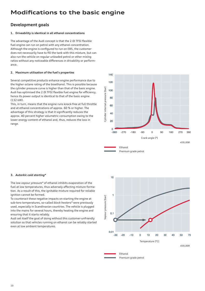
2. Maximum utilisation of the fuel's properties
Several competitive products enhance engine performance due to
the higher octane rating of the bioethanol. This is possible because
the cylinder pressure curve is higher than that of the basic engine.
Audi has optimised the 2.0l TFSI fl exible fuel engine for effi ciency,
hence its power output is identical to that of the basic engine
(132 kW).
This, in turn, means that the engine runs knock-free at full throttle
and at ethanol concentrations of approx. 60 % or higher. The
advantage of this strategy is that it signifi cantly reduces the
approx. 40 percent higher volumetric consumption owing to the
lower energy content of ethanol and, thus, reduces the loss in
range.
3. Autarkic cold starting*
The low vapour pressure* of ethanol inhibits evaporation of the
fuel at low temperatures, thus adversely aff ecting mixture forma-
tion. As a result of this, the ignitable mixture required for reliable
ignition cannot be formed.
To counteract these negative impacts on starting the engine at
sub-tero temperatures, so-called block heaters* were previously
used, especially in Scandinavian countries. The vehicle is plugged
into the mains for several hours, thereby heating the engine and
ensuring that it starts reliably.
Audi set itself the goal of doing without this customer-unfriendly
solution so that vehicles running on ethanol can be reliably started
even at low ambient temperatures.
439_008
439_009
Cyl
ind
er
inte
rna
l p
ress
ure
[b
ar]
Crank angle [°]
Va
po
ur
pre
ssu
re [
ba
r]
Temperature [°C]
Ethanol
Premium grade petrol
Ethanol
Premium grade petrol
Modifi cations to the basic engine
11
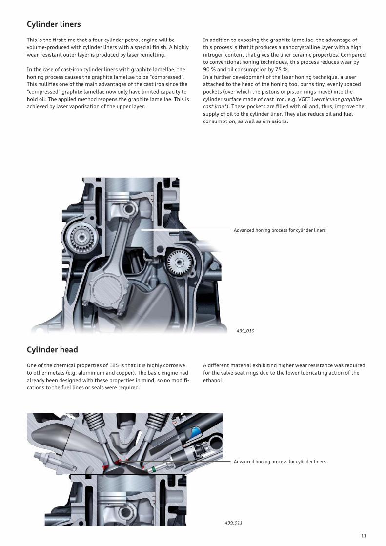
Cylinder liners
This is the fi rst time that a four-cylinder petrol engine will be
volume-produced with cylinder liners with a special fi nish. A highly
wear-resistant outer layer is produced by laser remelting.
In the case of cast-iron cylinder liners with graphite lamellae, the
honing process causes the graphite lamellae to be "compressed".
This nullifi es one of the main advantages of the cast iron since the
"compressed" graphite lamellae now only have limited capacity to
hold oil. The applied method reopens the graphite lamellae. This is
achieved by laser vaporisation of the upper layer.
Cylinder head
One of the chemical properties of E85 is that it is highly corrosive
to other metals (e.g. aluminium and copper). The basic engine had
already been designed with these properties in mind, so no modifi -
cations to the fuel lines or seals were required.
439_010
Advanced honing process for cylinder liners
439_011
Advanced honing process for cylinder liners
In addition to exposing the graphite lamellae, the advantage of
this process is that it produces a nanocrystalline layer with a high
nitrogen content that gives the liner ceramic properties. Compared
to conventional honing techniques, this process reduces wear by
90 % and oil consumption by 75 %.
In a further development of the laser honing technique, a laser
attached to the head of the honing tool burns tiny, evenly spaced
pockets (over which the pistons or piston rings move) into the
cylinder surface made of cast iron, e.g. VGCI (vermicular graphite
cast iron*). These pockets are fi lled with oil and, thus, improve the
supply of oil to the cylinder liner. They also reduce oil and fuel
consumption, as well as emissions.
A diff erent material exhibiting higher wear resistance was required
for the valve seat rings due to the lower lubricating action of the
ethanol.
12
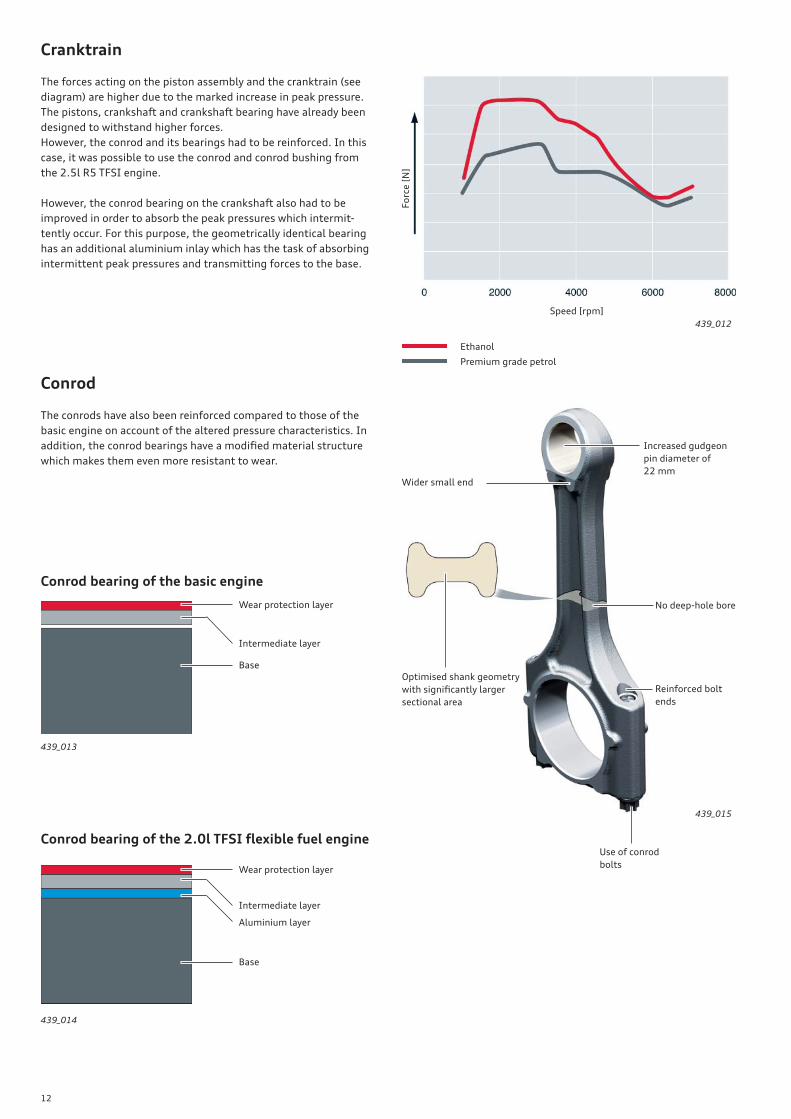
Cranktrain
The forces acting on the piston assembly and the cranktrain (see
diagram) are higher due to the marked increase in peak pressure.
The pistons, crankshaft and crankshaft bearing have already been
designed to withstand higher forces.
However, the conrod and its bearings had to be reinforced. In this
case, it was possible to use the conrod and conrod bushing from
the 2.5l R5 TFSI engine.
However, the conrod bearing on the crankshaft also had to be
improved in order to absorb the peak pressures which intermit-
tently occur. For this purpose, the geometrically identical bearing
has an additional aluminium inlay which has the task of absorbing
intermittent peak pressures and transmitting forces to the base.
Conrod
The conrods have also been reinforced compared to those of the
basic engine on account of the altered pressure characteristics. In
addition, the conrod bearings have a modifi ed material structure
which makes them even more resistant to wear.
Conrod bearing of the basic engine
Conrod bearing of the 2.0l TFSI fl exible fuel engine
439_015
Optimised shank geometry
with signifi cantly larger
sectional area
Use of conrod
bolts
No deep-hole bore
Reinforced bolt
ends
Increased gudgeon
pin diameter of
22 mmWider small end
439_013
439_014
439_012
Wear protection layer
Intermediate layer
Base
Wear protection layer
Intermediate layer
Base
Aluminium layer
Fo
rce
[N
]
Speed [rpm]
Ethanol
Premium grade petrol
13
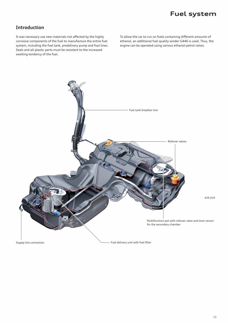
Introduction
It was necessary use new materials not aff ected by the highly
corrosive components of the fuel to manufacture the entire fuel
system, including the fuel tank, predelivery pump and fuel lines.
Seals and all plastic parts must be resistant to the increased
swelling tendency of the fuel.
To allow the car to run on fuels containing diff erent amounts of
ethanol, an additional fuel quality sender G446 is used. Thus, the
engine can be operated using various ethanol-petrol ratios.
439_016
Fuel tank breather line
Supply line connection
Multifunction pot with rollover valve and lever sensor
for the secondary chamber
Fuel delivery unit with fuel fi lter
Rollover valves
Fuel system
14
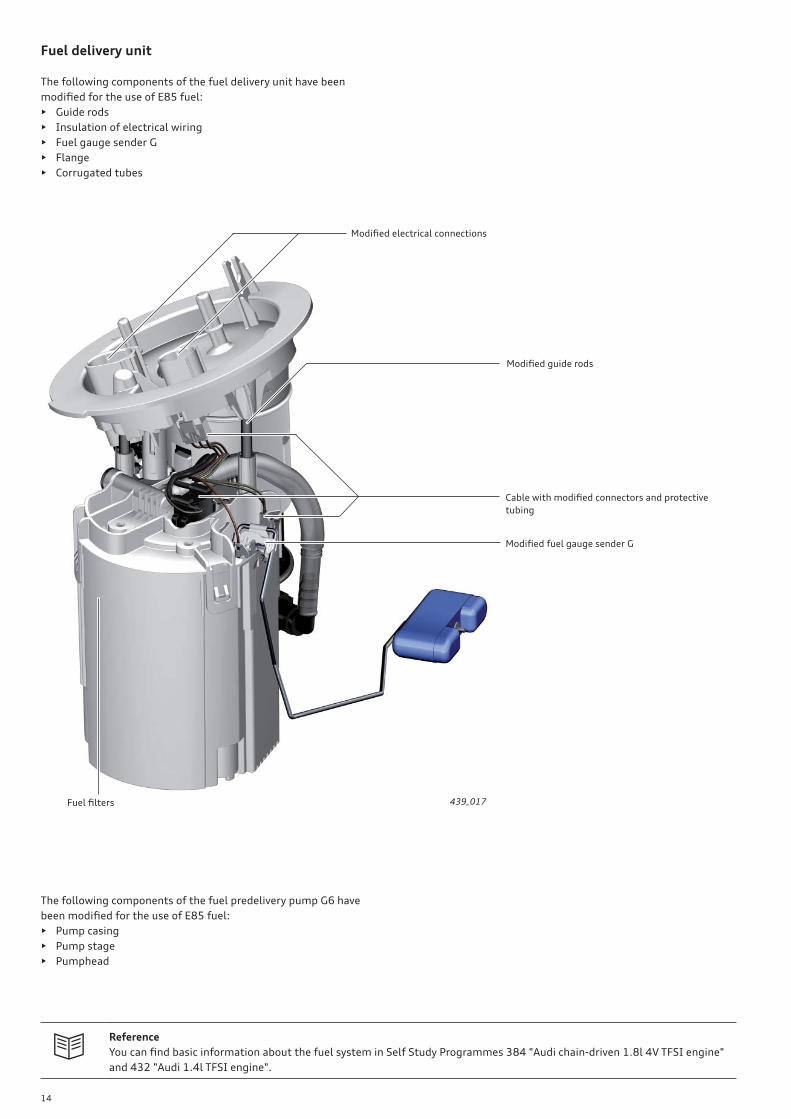
Fuel delivery unit
The following components of the fuel delivery unit have been
modifi ed for the use of E85 fuel:
• Guide rods
• Insulation of electrical wiring
• Fuel gauge sender G
• Flange
• Corrugated tubes
The following components of the fuel predelivery pump G6 have
been modifi ed for the use of E85 fuel:
• Pump casing
• Pump stage
• Pumphead
Reference
You can fi nd basic information about the fuel system in Self Study Programmes 384 "Audi chain-driven 1.8l 4V TFSI engine"
and 432 "Audi 1.4l TFSI engine".
439_017
Modifi ed electrical connections
Cable with modifi ed connectors and protective
tubing
Modifi ed fuel gauge sender G
Modifi ed guide rods
Fuel fi lters
15
!
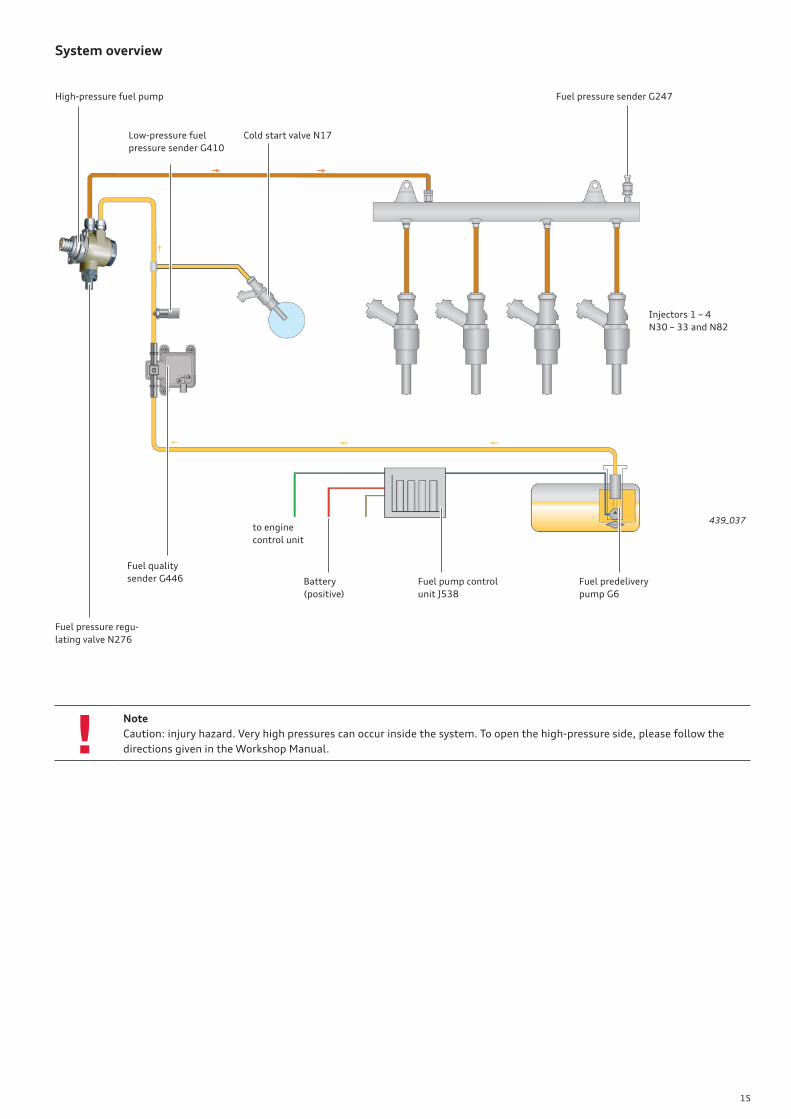
System overview
439_037
High-pressure fuel pump
Fuel pressure regu-
lating valve N276
to engine
control unit
Low-pressure fuel
pressure sender G410
Fuel pressure sender G247
Injectors 1 – 4
N30 – 33 and N82
Fuel predelivery
pump G6
Fuel pump control
unit J538
Battery
(positive)
Fuel quality
sender G446
Cold start valve N17
Note
Caution: injury hazard. Very high pressures can occur inside the system. To open the high-pressure side, please follow the
directions given in the Workshop Manual.
16
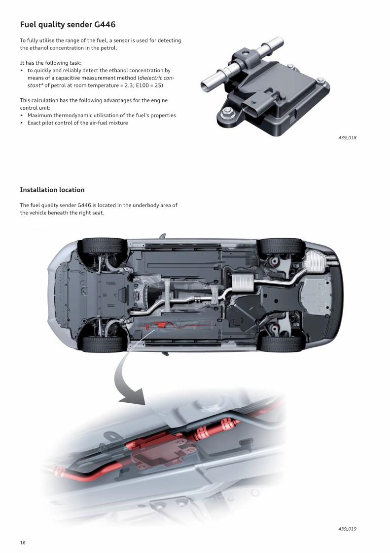
Fuel quality sender G446
To fully utilise the range of the fuel, a sensor is used for detecting
the ethanol concentration in the petrol.
It has the following task:
• to quickly and reliably detect the ethanol concentration by
means of a capacitive measurement method (dielectric con-
stant* of petrol at room temperature = 2.3; E100 = 25)
This calculation has the following advantages for the engine
control unit:
• Maximum thermodynamic utilisation of the fuel's properties
• Exact pilot control of the air-fuel mixture
Installation location
The fuel quality sender G446 is located in the underbody area of
the vehicle beneath the right seat.
439_018
439_019
17
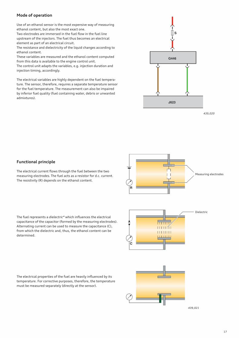
Mode of operation
Use of an ethanol sensor is the most expensive way of measuring
ethanol content, but also the most exact one.
Two electrodes are immersed in the fuel fl ow in the fuel line
upstream of the injectors. The fuel thus becomes an electrical
element as part of an electrical circuit.
The resistance and dielectricity of the liquid changes according to
ethanol content.
These variables are measured and the ethanol content computed
from this data is available to the engine control unit.
The control unit adapts the variables, e.g. injection duration and
injection timing, accordingly.
The electrical variables are highly dependent on the fuel tempera-
ture. The sensor, therefore, requires a separate temperature sensor
for the fuel temperature. The measurement can also be impaired
by inferior fuel quality (fuel containing water, debris or unwanted
admixtures).
Functional principle
The electrical current fl ows through the fuel between the two
measuring electrodes. The fuel acts as a resistor for d.c. current.
The resistivity (R) depends on the ethanol content.
The fuel represents a dielectric* which infl uences the electrical
capacitance of the capacitor (formed by the measuring electrodes).
Alternating current can be used to measure the capacitance (C),
from which the dielectric and, thus, the ethanol content can be
determined.
The electrical properties of the fuel are heavily infl uenced by its
temperature. For corrective purposes, therefore, the temperature
must be measured separately (directly at the sensor).
439_020
439_021
Measuring electrodes
Dielectric
18
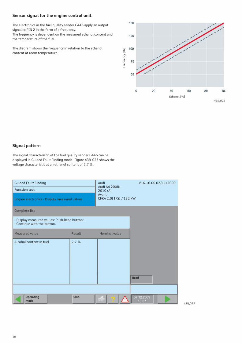
Sensor signal for the engine control unit
The electronics in the fuel quality sender G446 apply an output
signal to PIN 2 in the form of a frequency.
The frequency is dependent on the measured ethanol content and
the temperature of the fuel.
The diagram shows the frequency in relation to the ethanol
content at room temperature.
Signal pattern
The signal characteristic of the fuel quality sender G446 can be
displayed in Guided Fault Finding mode. Figure 439_023 shows the
voltage characteristic at an ethanol content of 2.7 %.
Fre
qu
en
cy [
Hz]
Ethanol [%]
439_022
Guided Fault Finding Audi V16.16.00 02/11/2009Audi A4 2008>2010 (A)AvantCFKA 2.0l TFSI / 132 kW
Function test
Engine electronics - Display measured values
Complete list
Measured value
Alcohol content in fuel 2.7 %
Result Nominal value
- Display measured values: Push Read button:- Continue with the button.
Read
SkipOperating
mode439_023
19
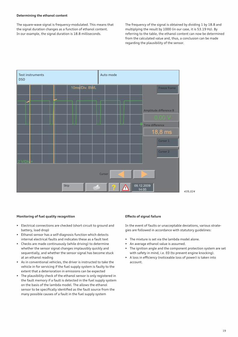
Determining the ethanol content
The square-wave signal is frequency-modulated. This means that
the signal duration changes as a function of ethanol content.
In our example, the signal duration is 18.8 milliseconds.
Monitoring of fuel quality recognition
• Electrical connections are checked (short circuit to ground and
battery, load drop)
• Ethanol sensor has a self-diagnosis function which detects
internal electrical faults and indicates these as a fault text
• Checks are made continuously (while driving) to determine
whether the sensor signal changes implausibly quickly and
sequentially, and whether the sensor signal has become stuck
at an ethanol reading
• As in conventional vehicles, the driver is instructed to take the
vehicle in for servicing if the fuel supply system is faulty to the
extent that a deterioration in emissions can be expected
• The plausibility check of the ethanol sensor is only registered in
the fault memory if a fault is detected in the fuel supply system
on the basis of the lambda model. The allows the ethanol
sensor to be specifi cally identifi ed as the fault source from the
many possible causes of a fault in the fuel supply system
Eff ects of signal failure
In the event of faults or unacceptable deviations, various strate-
gies are followed in accordance with statutory guidelines:
• The mixture is set via the lambda model alone.
• An average ethanol value is assumed.
• The ignition angle and the component protection system are set
with safety in mind, i.e. E0 (to prevent engine knocking).
• A loss in effi ciency (noticeable loss of power) is taken into
account.
The frequency of the signal is obtained by dividing 1 by 18.8 and
multiplying the result by 1000 (in our case, it is 53.19 Hz). By
referring to the table, the ethanol content can now be determined
from the calculated value and, thus, a conclusion can be made
regarding the plausibility of the sensor.
Test instruments
DSO
Auto mode
Freeze frame
Cursor 1
Time diff erence
Amplitude diff erence B
Cursor 2
Cursor
Skip
439_024
20
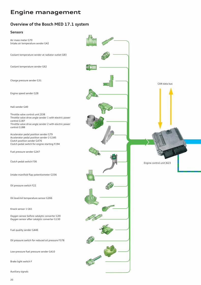
Overview of the Bosch MED 17.1 system
Sensors
Air mass meter G70
Intake air temperature sender G42
Coolant temperature sender G62
Coolant temperature sender at radiator outlet G83
Charge pressure sender G31
Engine speed sender G28
Engine control unit J623
CAN data bus
Hall sender G40
Throttle valve control unit J338
Throttle valve drive angle sender 1 with electric power
control G187
Throttle valve drive angle sender 2 with electric power
control G188
Accelerator pedal position sender G79
Accelerator pedal position sender 2 G185
Clutch position sender G476
Clutch pedal switch for engine starting F194
Clutch pedal switch F36
Fuel pressure sender G247
Oil pressure switch F22
Intake manifold fl ap potentiometer G336
Oil level/oil temperature sensor G266
Knock sensor 1 G61
Oxygen sensor before catalytic converter G39
Oxygen sensor after catalytic converter G130
Fuel quality sender G446
Oil pressure switch for reduced oil pressure F378
Low-pressure fuel pressure sender G410
Brake light switch F
Auxiliary signals
Engine management
21
Diagnostic port
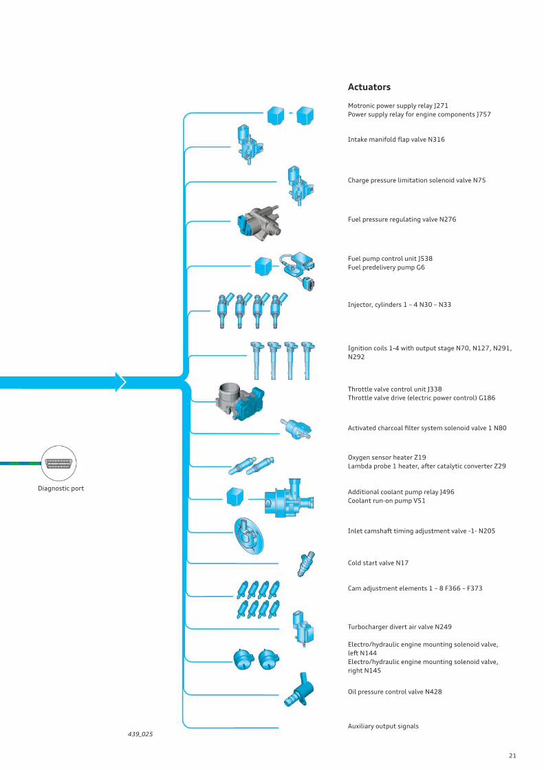
Actuators
Motronic power supply relay J271
Power supply relay for engine components J757
Intake manifold fl ap valve N316
Charge pressure limitation solenoid valve N75
Fuel pressure regulating valve N276
Fuel pump control unit J538
Fuel predelivery pump G6
Injector, cylinders 1 – 4 N30 – N33
Ignition coils 1-4 with output stage N70, N127, N291,
N292
Throttle valve control unit J338
Throttle valve drive (electric power control) G186
Activated charcoal fi lter system solenoid valve 1 N80
Oxygen sensor heater Z19
Lambda probe 1 heater, after catalytic converter Z29
Additional coolant pump relay J496
Coolant run-on pump V51
Inlet camshaft timing adjustment valve -1- N205
Cold start valve N17
Cam adjustment elements 1 – 8 F366 – F373
Turbocharger divert air valve N249
Electro/hydraulic engine mounting solenoid valve,
left N144
Electro/hydraulic engine mounting solenoid valve,
right N145
Oil pressure control valve N428
Auxiliary output signals439_025
22
Cold starting
Using the information on fuel quality, the correct mixture can be
set immediately after cold starting.
The vapour pressure* and, thus, the carburetion characteristics
vary according to fuel quality (the ethanol content in the petrol).
At about 13 °C, pure ethanol (E100) has the same vapour pressure
as commercially available petrol at –30 °C. (refer to "Autarkic cold
starting" on page 10)
Thanks to the FSI* technology, it is possible to implement a
high-pressure multi-injection fuel system. This system renders
engine preheating superfl uous and ensures reliable cold starting at
temperatures as low as –25 °C.
The multi-injection fuel system has three injection windows
instead of the previous two.
Whereas in the twin injection system the injection windows are
during the intake and compression strokes, in the multi-injection
system the compression stroke injection is subdivided into two
variable injection packages. The timing and quantity of the indi-
vidual injection packages are freely selectable.
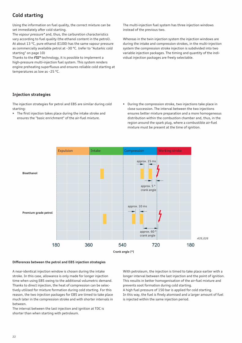
Injection strategies
The injection strategies for petrol and E85 are similar during cold
starting:
• The fi rst injection takes place during the intake stroke and
ensures the "basic enrichment" of the air-fuel mixture.
Diff erences between the petrol and E85 injection strategies
A near-identical injection window is chosen during the intake
stroke. In this case, allowance is only made for longer injection
time when using E85 owing to the additional volumetric demand.
Thanks to direct injection, the heat of compression can be selec-
tively utilised for mixture formation during cold starting. For this
reason, the two injection packages for E85 are timed to take place
much later in the compression stroke and with shorter intervals in
between.
The interval between the last injection and ignition at TDC is
shorter than when starting with petroleum.
With petroleum, the injection is timed to take place earlier with a
longer interval between the last injection and the point of ignition.
This results in better homogenisation of the air-fuel mixture and
prevents soot formation during cold starting.
A high fuel pressure of 150 bar is applied for cold starting.
In this way, the fuel is fi nely atomised and a larger amount of fuel
is injected within the same injection period.
Expulsion Intake Compression Working stroke
approx. 15 ms
approx. 5 °
crank angle
approx. 10 ms
approx. 60 °
crank angle
Bioethanol
Premium grade petrol
Crank angle [°]
439_026
• During the compression stroke, two injections take place in
close succession. The interval between the two injections
ensures better mixture preparation and a more homogeneous
distribution within the combustion chamber and, thus, in the
region around the spark plug, where a combustible air-fuel
mixture must be present at the time of ignition.
23
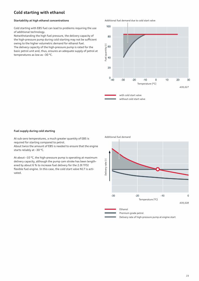
Fuel supply during cold starting
At sub-zero temperatures, a much greater quantity of E85 is
required for starting compared to petrol.
About twice the amount of E85 is needed to ensure that the engine
starts reliably at –30 °C.
At about –10 °C, the high-pressure pump is operating at maximum
delivery capacity, although the pump cam stroke has been length-
ened by about 6 % to increase fuel delivery for the 2.0l TFSI
fl exible fuel engine. In this case, the cold start valve N17 is acti-
vated.
Cold starting with ethanol
Startability at high ethanol concentrations
Cold starting with E85 fuel can lead to problems requiring the use
of additional technology.
Notwithstanding the high fuel pressure, the delivery capacity of
the high-pressure pump during cold starting may not be suffi cient
owing to the higher volumetric demand for ethanol fuel.
The delivery capacity of the high-pressure pump is rated for the
basic petrol unit and, thus, ensures an adequate supply of petrol at
temperatures as low as –30 °C.
Additional fuel demand due to cold start valve
Additional fuel demand
Temperature [°C]
439_027
with cold start valve
Ethanol
without cold start valve
Premium grade petrol
Delivery rate of high-pressure pump at engine start
Temperature [°C]
439_028
De
live
ry r
ate
[-]
Fu
el
qu
an
tity
[-]
24
Cold start valve N17
To ensure that enough fuel is available for starting at temperatures
below –10 °C, an additional cold start valve has been integrated in
the low-pressure fuel system.
The cold start valve is positioned downstream of the throttle valve
in the intake manifold.
The distribution of fuel between the high-pressure system and the
low-pressure system is confi gured so that the cold start valve
admits only as much fuel as cannot be delivered by the high-
pressure pump.
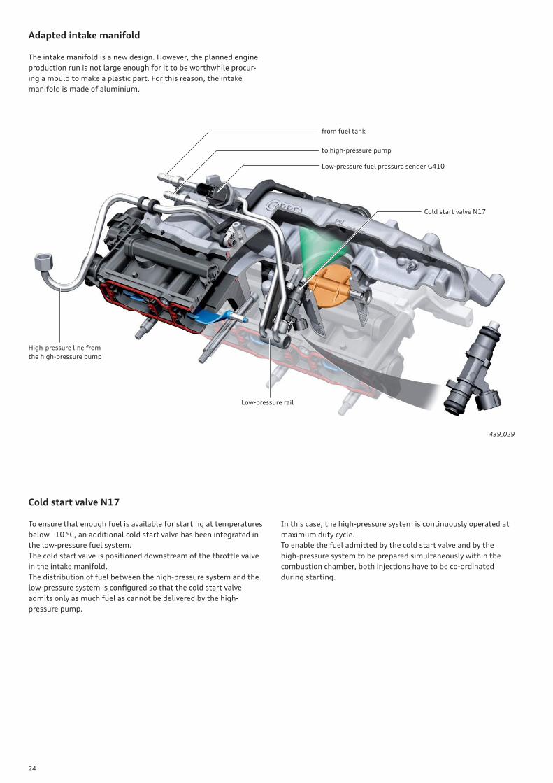
Adapted intake manifold
The intake manifold is a new design. However, the planned engine
production run is not large enough for it to be worthwhile procur-
ing a mould to make a plastic part. For this reason, the intake
manifold is made of aluminium.
439_029
Low-pressure fuel pressure sender G410
High-pressure line from
the high-pressure pump
Cold start valve N17
from fuel tank
to high-pressure pump
Low-pressure rail
In this case, the high-pressure system is continuously operated at
maximum duty cycle.
To enable the fuel admitted by the cold start valve and by the
high-pressure system to be prepared simultaneously within the
combustion chamber, both injections have to be co-ordinated
during starting.
25
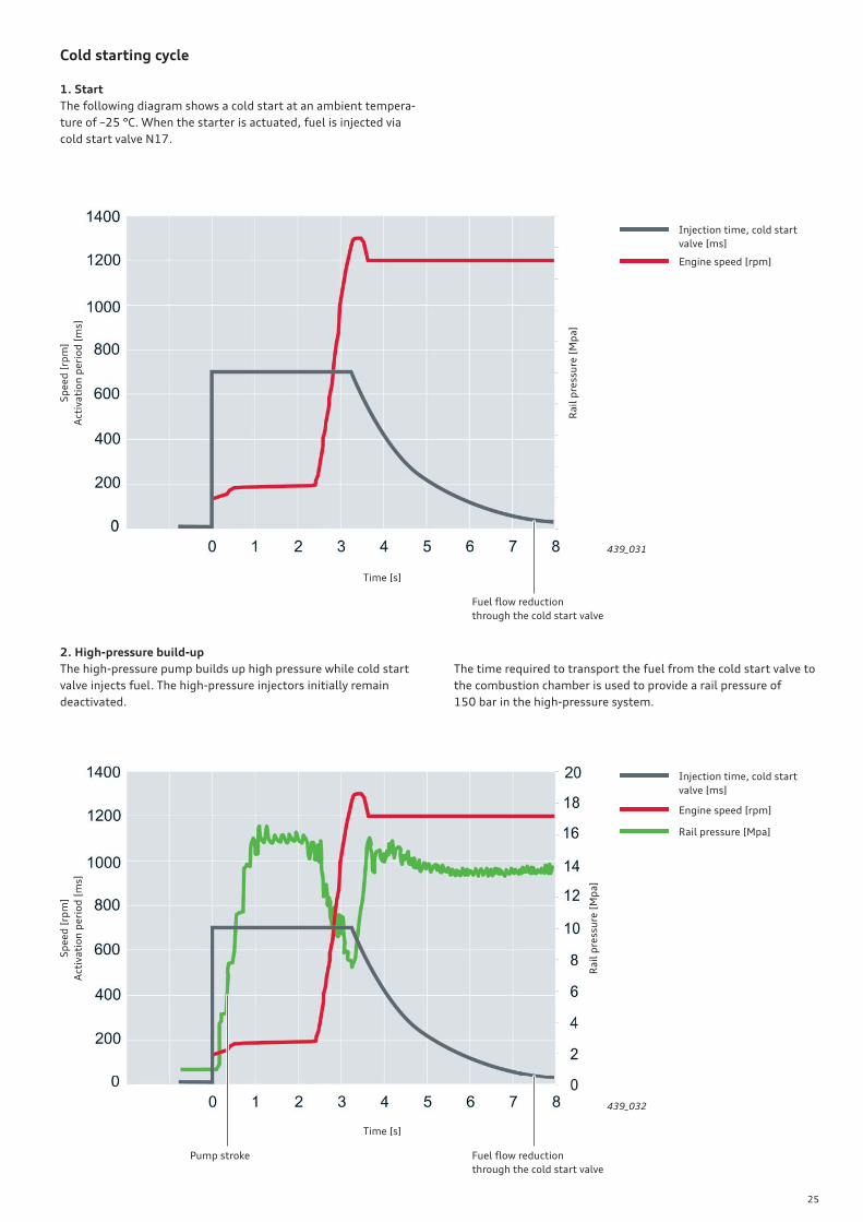
Cold starting cycle
1. Start
The following diagram shows a cold start at an ambient tempera-
ture of –25 °C. When the starter is actuated, fuel is injected via
cold start valve N17.
2. High-pressure build-up
The high-pressure pump builds up high pressure while cold start
valve injects fuel. The high-pressure injectors initially remain
deactivated.
The time required to transport the fuel from the cold start valve to
the combustion chamber is used to provide a rail pressure of
150 bar in the high-pressure system.
Time [s]
Time [s]
Sp
ee
d [
rpm
]
Act
iva
tio
n p
eri
od
[m
s]
Sp
ee
d [
rpm
]
Act
iva
tio
n p
eri
od
[m
s]
Ra
il p
ress
ure
[M
pa
]
Ra
il p
ress
ure
[M
pa
]
Pump stroke Fuel fl ow reduction
through the cold start valve
Fuel fl ow reduction
through the cold start valve
439_032
439_031
Injection time, cold start
valve [ms]
Injection time, cold start
valve [ms]
Engine speed [rpm]
Engine speed [rpm]
Rail pressure [Mpa]
26
Fuel ingress into the engine oil and fuel extraction from the engine oil
Introduction
Lubricant, fuel and water form a complex emulsion which has the
capacity to leach active agents out of and contaminate the oil.
A high fuel content in the engine oil gives the oil a very low viscos-
ity, thereby thinning out the lubrication fi lter. In addition to this,
cavitation* can occur due to rapid vaporisation of the fuel.
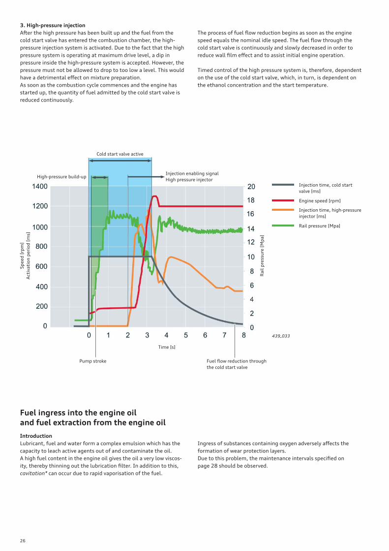
3. High-pressure injection
After the high pressure has been built up and the fuel from the
cold start valve has entered the combustion chamber, the high-
pressure injection system is activated. Due to the fact that the high
pressure system is operating at maximum drive level, a dip in
pressure inside the high-pressure system is accepted. However, the
pressure must not be allowed to drop to too low a level. This would
have a detrimental eff ect on mixture preparation.
As soon as the combustion cycle commences and the engine has
started up, the quantity of fuel admitted by the cold start valve is
reduced continuously.
The process of fuel fl ow reduction begins as soon as the engine
speed equals the nominal idle speed. The fuel fl ow through the
cold start valve is continuously and slowly decreased in order to
reduce wall fi lm eff ect and to assist initial engine operation.
Timed control of the high pressure system is, therefore, dependent
on the use of the cold start valve, which, in turn, is dependent on
the ethanol concentration and the start temperature.
Time [s]
Sp
ee
d [
rpm
]
Act
iva
tio
n p
eri
od
[m
s]
Ra
il p
ress
ure
[M
pa
]
Injection enabling signal
High pressure injectorHigh-pressure build-up
Cold start valve active
Pump stroke Fuel fl ow reduction through
the cold start valve
439_033
Injection time, cold start
valve [ms]
Engine speed [rpm]
Injection time, high-pressure
injector [ms]
Rail pressure [Mpa]
Ingress of substances containing oxygen adversely aff ects the
formation of wear protection layers.
Due to this problem, the maintenance intervals specifi ed on
page 28 should be observed.
27
Eff ects on the engine management system
Ingress of E85 fuel into the engine oil occurs during the warm-up
phase due to the larger quantity of fuel injected and, in particular,
the eff ect of the fi xed boiling point.
During cold starting, a larger additional amount of fuel is injected
into the engine to provide for the additional volumetric demand
and additional start enrichment of the air-fuel mixture. However,
this is the smallest fraction of the total amount injected during the
entire warm-up phase.
The fuel which is not directly involved in the combustion process
and comes into contact with engine components that have not yet
reached a temperature of 78 °C re-condenses and is either expelled
by the exhaust system or bypasses the piston rings and is
entrained in the engine oil.
The process continues until all engine components in the combus-
tion chamber have safely exceeded the boiling point of ethanol.
This point is reached at an engine oil temperature of approx. 35 °C.
From then on, more ethanol is extracted from the engine oil than
is entrained in the engine oil.
Fuel ingress into the engine oil can be particularly high if the
vehicle is frequently driven short distances in succession.
Volume [%]
Engine oil temperature [°C]
Tem
pe
ratu
re [
°C]
Ing
ress
am
ou
nt
[%]
Ingress > extraction Extraction > ingress
Ethanol
Premium grade petrol
439_034
439_035
Fuel extraction process
At an engine oil temperature of 78 °C, the ethanol evaporates
completely. The evaporated ethanol is now admitted into the
combustion system via the crankcase breather.
In this case, the engine management system must take special
measures at idle so that stoichiometric combustion* can take
place.
Depending on the situation and the ethanol concentration in the
fuel, the following measures may be taken:
• The injected fuel mass is decreased by reducing the injection
time of the injectors.
• If this is not enough, the fuel pressure is reduced to 30 bar.
• In extreme cases, the ignition timing can even be retarded.
• Finally, the idling speed is additionally increased.
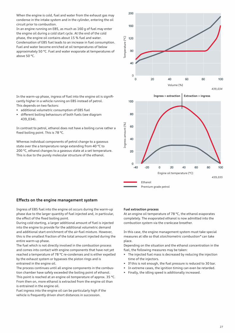
In the warm-up phase, ingress of fuel into the engine oil is signifi -
cantly higher in a vehicle running on E85 instead of petrol.
This depends on two factors:
• additional volumetric consumption of E85 fuel
• diff erent boiling behaviours of both fuels (see diagram
439_034).
In contrast to petrol, ethanol does not have a boiling curve rather a
fi xed boiling point. This is 78 °C.
Whereas individual components of petrol change to a gaseous
state over the a temperature range extending from 40 °C to
200 °C, ethanol changes to a gaseous state at a set temperature.
This is due to the purely molecular structure of the ethanol.
When the engine is cold, fuel and water from the exhaust gas may
condense in the intake system and in the cylinder, entering the oil
circuit prior to combustion.
In an engine running on E85, as much as 160 g of fuel may enter
the engine oil during a cold start cycle. At the end of the cold
phase, the engine oil contains about 15 % fuel and water.
Condensation of E85 fuel leads to an increase in fuel consumption.
Fuel and water become enriched at oil temperatures of below
approximately 50 °C. Fuel and water evaporate at temperatures of
above 50 °C.
28
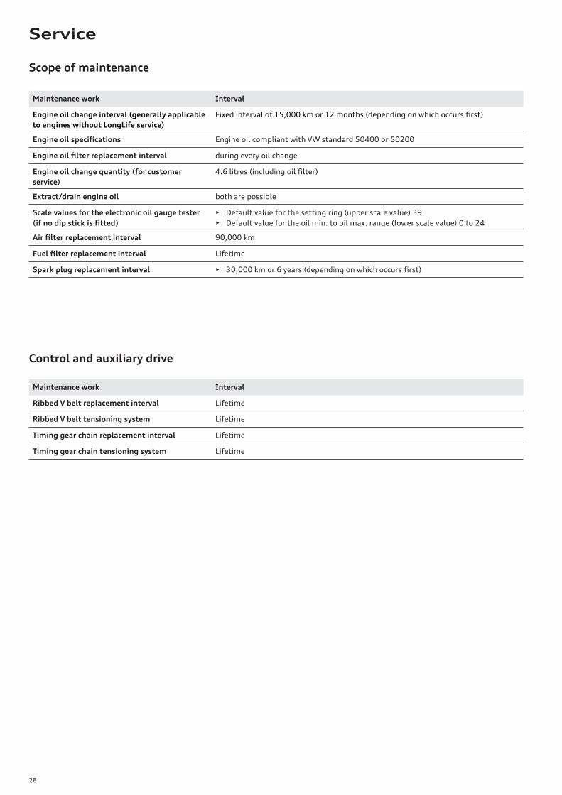
Scope of maintenance
Control and auxiliary drive
Maintenance work Interval
Engine oil change interval (generally applicable
to engines without LongLife service)
Fixed interval of 15,000 km or 12 months (depending on which occurs fi rst)
Engine oil specifi cations Engine oil compliant with VW standard 50400 or 50200
Engine oil fi lter replacement interval during every oil change
Engine oil change quantity (for customer
service)
4.6 litres (including oil fi lter)
Extract/drain engine oil both are possible
Scale values for the electronic oil gauge tester
(if no dip stick is fi tted)
• Default value for the setting ring (upper scale value) 39
• Default value for the oil min. to oil max. range (lower scale value) 0 to 24
Air fi lter replacement interval 90,000 km
Fuel fi lter replacement interval Lifetime
Spark plug replacement interval • 30,000 km or 6 years (depending on which occurs fi rst)
Maintenance work Interval
Ribbed V belt replacement interval Lifetime
Ribbed V belt tensioning system Lifetime
Timing gear chain replacement interval Lifetime
Timing gear chain tensioning system Lifetime
Service
29
Glossary
Autarkic cold starting
A cold starting system which runs, or can be run, independently of
other components (block heater). This facilitates high-pressure
multi injection based on FSI technology, rendering engine preheat-
ing superfl uous and enabling the engine to be reliably cold started
at temperatures as low as –25 °C.
AVS
Audi valvelift system
The Audi valvelift system has been developed to optimise the
exhaust-intake cycles in internal combustion engines. In the 2.0l
TFSI engine, the system is not installed on the intake side rather
on the exhaust side. To is achieved by separation of the fi ring order,
and hence pulse charging of the exhaust turbocharger.
Block heater
To counteract the detrimental eff ects of the low ethanol vapour
pressure on engine starting at sub-zero temperatures, so-called
block heaters are used, especially in Scandinavian countries. The
vehicle is plugged into the mains for several hours in order to heat
the engine block, thereby ensuring that the ignitable air-fuel
mixture combusts and that the engine starts reliably.
BTL fuel
Biomass To Liquid
These are synthetic fuels produced from biomass. They can be used
to produce, as an end product, fuels that slightly diff er chemically
from conventional fuels, such as petrol or diesel, but which are
suitable for use in petrol or diesel engines. BTL fuels are second-
generation biofuels.
Cavitation
(lat.: “cavitare”, meaning to “hollow out”) Is the formation and
collapse of cavities within liquids due to pressure fl uctations. A
distinction is made between two borderline cases, between which
there are many transitional forms. In the case of pressure cavita-
tion or hard (transient) cavitation, the cavities mainly contain
vapour of the enveloping fl uid. Such cavities collapse by bubble
implosion under the infl uence of external pressure (microscopic
vapour shock). In the case of soft or stable gas cavitation, gases
dissolved from the fl uid enter the cavitation bubbles and soften or
prevent their collapse.
Dielectric
Is a low-conducting or non-conducting nonmetallic substance
which is subjected to electrical or electromagnetic fi elds and
whose charge carriers are generally not freely moveable. A dielec-
tric can be either a gas, a liquid or a solid.
Dielectric constant (permittivity constant)
Is the ratio of ε to the electrical fi eld constant ε0 (permittivity of
the vacuum) εr = ε/ε
0. The dimensionless variable ε
r describes the
fi eld weakening eff ect of dielectric polarisation within electrically
insulating materials.
Enthalpy of vaporisation
The enthalpy of vaporisation ΔVH is the energy required to trans-
form 1 mole of any substance from a liquid to a gaseous state
under isothermal and isobar conditions.
FSI
Fuel Stratifi ed Injection
A technology used on petrol engines of the VW Group for direct
fuel injection into the combustion chamber at pressures of higher
than 100 bar.
Octane
A measure of a fuel’s ability to resist burning prematurely or
uncontrollably by spontaneous combustion in the combustion
chamber. The higher the octane rating, the greater the energy yield
of the fuel.
Stoichiometric combustion
Describes the air-fuel ratio at which all the fuel molecules react
fully with the oxygen in the air, without oxygen being absent or any
uncombusted oxygen remaining.
It takes 14.8 kg of air to completely combust 1 kilogram of regular
unleaded petrol, 14.7 kg of air to completely combust 1 kilogram
of premium unleaded petrol, 9.0 kg of air to completely combust
1 kilogram of ethanol and 14.5 kg of air to completely combust
1 kilogram of diesel.
Vapour pressure
Is a material and temperature dependent gas pressure and is the
ambient pressure below which a liquid – at constant temperature
– begins to enter a gaseous state.
Vermicular graphite casting
Is an iron-carbon casting material containing graphite in a ver-
micular form (vermiculus is latin, meaning "little worm"). In
general, the term "cast iron with vermicular graphite" is used if at
least 80 % of the graphite is vermicular and the remainder is in a
spheroidal - but not lamellar - form. Cast iron with vermicular
graphite has a well-defi ned modulus of 0.2 %. On average, its
strength is at least 50 % higher than the strength of cast iron with
lamellar graphite, but is dependent both on the wall thickness and
on the silicon content. Compared to grey cast iron, weight savings
of up to 15 % can be achieved by the reduction of wall thickness.
Annex
30
1. What is meant by fl exible fuel?
a) The engine can run on petrol and liquefi ed petroleum gas.
b) The engine can run on petrol and diesel.
c) The engine can run on petrol and bioethanol.
2. What is the task of sender G446?
a) The fuel pressure sender gauges the fuel pressure in the rail.
b) The fuel pressure sender measures the ethanol concentration.
c) The fuel pressure sender is responsible for exact air-fuel mixture pre-control.
3. What are the characteristic features of the 2.0l TFSI fl exible fuel engine?
a) Use of the 2.0l TFSI engine with AVS and start-stop technology.
b) No noticeable drawbacks in terms of ride comfort and driving pleasure.
c) Development of a special engine pre-heating system for countries with cold climates.
4. What does the term "bioethanol" mean?
a) A marketing name.
b) An organic hydrocarbon compound.
c) A fuel produced from fast-growing plants, timber varieties and organic wastes.
5. What modifi cations does the 2.0l TFSI fl exible fuel engine have compared to the basic engine?
a) Use of a block heater.
b) Use of reinforced conrods.
c) Increased engine power.
6. What modifi cations have been made to the fuel system?
a) Use of a modifi ed fuel tank.
b) Use of a modifi ed fuel delivery unit.
c) Use of a fuel quality sender G446.
7. What are the special features of the engine management system?
a) Shorter injection times at idle.
b) Increased entrainment of fuel components not involved in the combustion process occurs up to an oil temperature of 35 °C.
c) Reduction in idle speed.
8. What are the points to note when servicing the vehicle?
a) Fixed service intervals and no LongLife Service.
b) Spark plug replacement every 60,000 km.
c) Replacement of the fuel fi lter during every service.
Test solutions:
1 c; 2 bc; 3 ab; 4 bc; 5 b; 6 bc; 7 ab; 8 a
□□□
□□□
□□□
□□□
□□□
□□□
□□□
□□□
Test your knowledge
31
Summary
Ethanol is a practical and inexpensive alternative to petrol. It does
necessitates neither the introduction of fundamentally new engine
technology nor the installation of fuel pressure accumulators, such
as when running a vehicle on LPG liquid gas or CNG natural gas.
The Audi 2.0l TFSI fl exible fuel engine is the world's fi rst fl ex fuel
engine incorporating TFSI technology. It utilises biofuel E85 and
conventional petrol to achieve optimal effi ciency without any
limitations. The CO2 balance can be improved by up to 75 percent
by using regenerative biofuels.
Thanks to the newly developed high-pressure multi injection
system, the 2.0l TFSI fl exible fuel engine is also able to start at
low ambient temperatures when running on E85.
Compared to its premium-segment competitors, the Audi A4 with
2.0l TFSI fl exible fuel engine represents a new benchmark. While
delivering identical performance to the basic petrol version, the
Audi A4 with 2.0l TFSI fl exible fuel engine is easily the best vehicle
concept in its class in terms of fuel economy.
Self Study Programmes
439_038 439_039 439_040 439_041
SSP 384 Audi chain-driven 1.8l 4V TFSI engine, order number: A06.5S00.29.20
SSP 436 Modifi cations to the chain-driven 4-cylinder TFSI engine, order number: A08.5S00.52.20
SSP 411 Audi 2.8l and 3.2l FSI engine with Audi valvelift system, order number: A07.5S00.42.20
SSP 451 Audi TT RS with 2.5l R5 TFSI engine, order number: A10.5S00.67.20

Audi Vorsprung durch Technik
AudiService Training
43
9
Audi 2.0l TFSI fl exible fuel engine
All rights reserved.
Technical specifi cations subject to
change.
Copyright
AUDI AG
I/VK-35
AUDI AG
D-85045 Ingolstadt
Technical status 05/10
Printed in Germany
A10.5S00.57.20
Self-Study Programme 439