Embed Size (px)
Citation preview
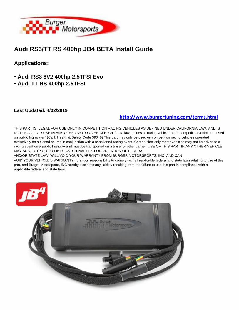
Audi RS3/TT RS 400hp JB4 BETA Install Guide
Applications:
• Audi RS3 8V2 400hp 2.5TFSI Evo
• Audi TT RS 400hp 2.5TFSI
Last Updated: 4/02/2019
THIS PART IS LEGAL FOR USE ONLY IN COMPETITION RACING VEHICLES AS DEFINED UNDER CALIFORNIA LAW, AND IS
NOT LEGAL FOR USE IN ANY OTHER MOTOR VEHICLE. California law defines a "racing vehicle" as "a competition vehicle not used
on public highways." (Calif. Health & Safety Code 39048) This part may only be used on competition racing vehicles operated
exclusively on a closed course in conjunction with a sanctioned racing event. Competition-only motor vehicles may not be driven to a
racing event on a public highway and must be transported on a trailer or other carrier. USE OF THIS PART IN ANY OTHER VEHICLE
MAY SUBJECT YOU TO FINES AND PENALTIES FOR VIOLATION OF FEDERAL
AND/OR STATE LAW, WILL VOID YOUR WARRANTY FROM BURGER MOTORSPORTS, INC, AND CAN
VOID YOUR VEHICLE'S WARRANTY. It is your responsibility to comply with all applicable federal and state laws relating to use of this
part, and Burger Motorsports, INC hereby disclaims any liability resulting from the failure to use this part in compliance with all
applicable federal and state laws.
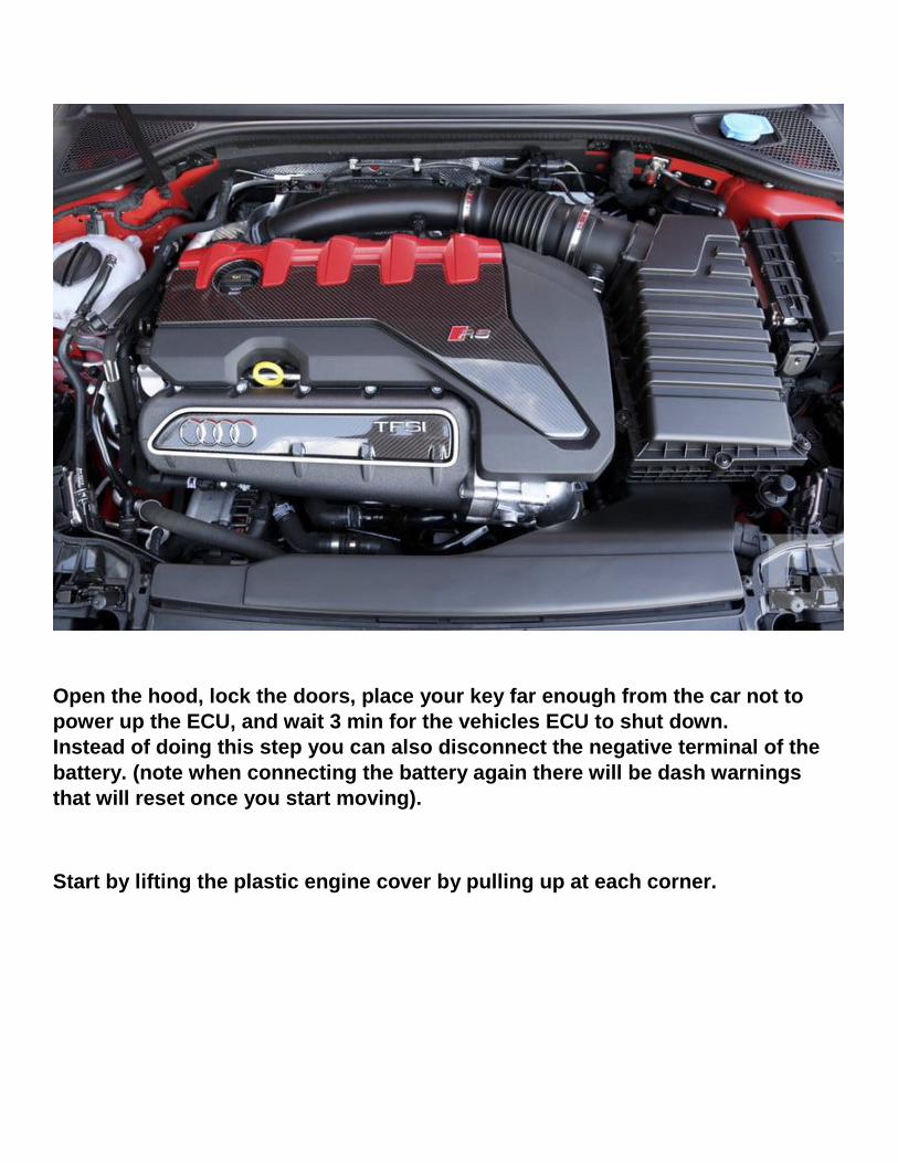
Open the hood, lock the doors, place your key far enough from the car not to
power up the ECU, and wait 3 min for the vehicles ECU to shut down.
Instead of doing this step you can also disconnect the negative terminal of the
battery. (note when connecting the battery again there will be dash warnings
that will reset once you start moving).
Start by lifting the plastic engine cover by pulling up at each corner.
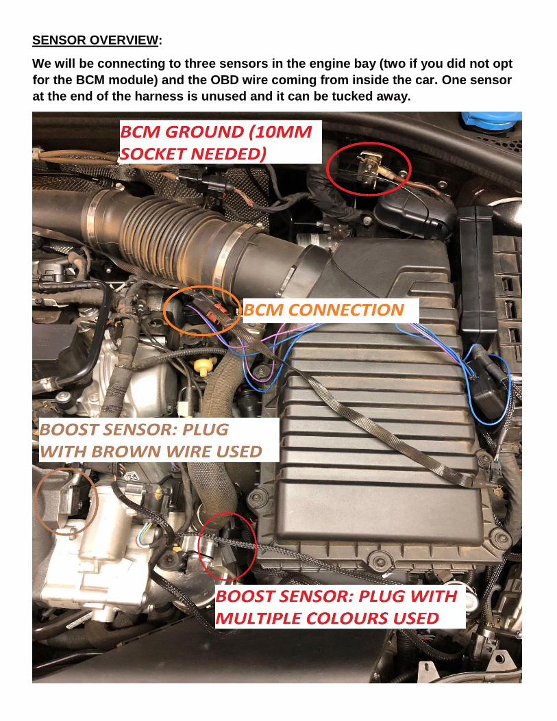
SENSOR OVERVIEW:
We will be connecting to three sensors in the engine bay (two if you did not opt
for the BCM module) and the OBD wire coming from inside the car. One sensor
at the end of the harness is unused and it can be tucked away.
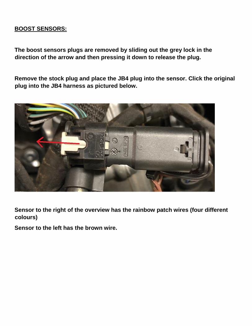
BOOST SENSORS:
The boost sensors plugs are removed by sliding out the grey lock in the
direction of the arrow and then pressing it down to release the plug.
Remove the stock plug and place the JB4 plug into the sensor. Click the original
plug into the JB4 harness as pictured below.
Sensor to the right of the overview has the rainbow patch wires (four different
colours)
Sensor to the left has the brown wire.
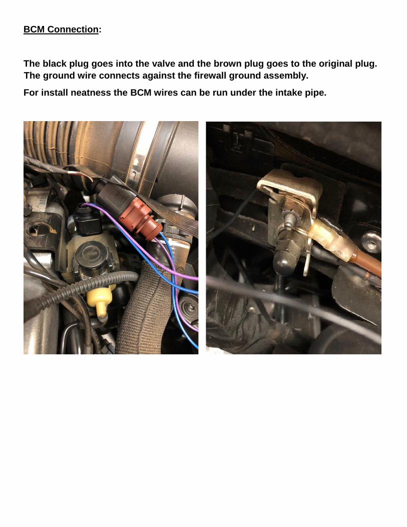
BCM Connection:
The black plug goes into the valve and the brown plug goes to the original plug.
The ground wire connects against the firewall ground assembly.
For install neatness the BCM wires can be run under the intake pipe.
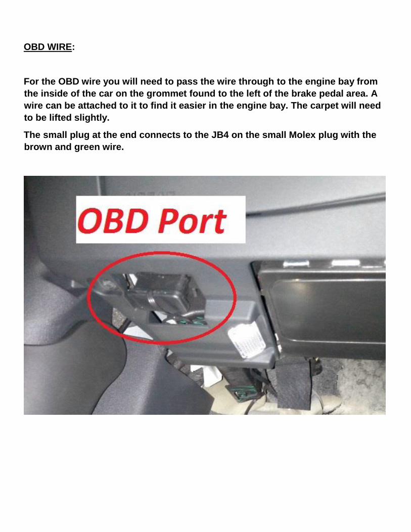
OBD WIRE:
For the OBD wire you will need to pass the wire through to the engine bay from
the inside of the car on the grommet found to the left of the brake pedal area. A
wire can be attached to it to find it easier in the engine bay. The carpet will need
to be lifted slightly.
The small plug at the end connects to the JB4 on the small Molex plug with the
brown and green wire.
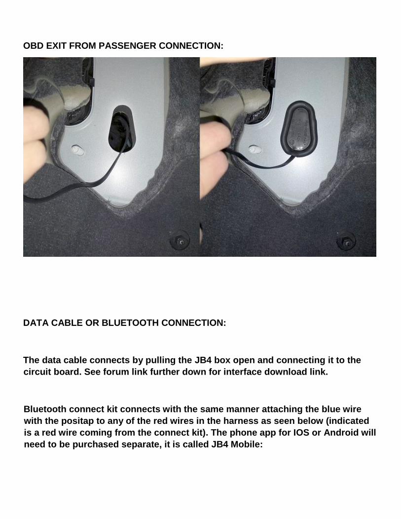
OBD EXIT FROM PASSENGER CONNECTION:
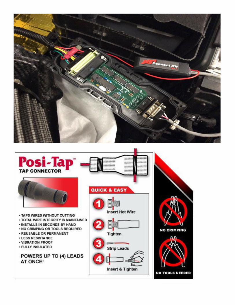
DATA CABLE OR BLUETOOTH CONNECTION:
The data cable connects by pulling the JB4 box open and connecting it to the
circuit board. See forum link further down for interface download link.
Bluetooth connect kit connects with the same manner attaching the blue wire
with the positap to any of the red wires in the harness as seen below (indicated
is a red wire coming from the connect kit). The phone app for IOS or Android will
need to be purchased separate, it is called JB4 Mobile:

The install is now complete. If you disconnected the battery on start up you will
have several dash warnings. The modules will reset themselves as you drive of
and the ECU completes a safety test.
Map information, Bluetooth module and general information on the unit can be
found at our support forum here:
https://www.n54tech.com/forums/showthread.php?t=56120
For technical support and sales queries email [email protected]