Embed Size (px)
Citation preview
Features andBenefits
Morph
the AVPthe AVP
• Advanced Audio Jackfield Concept • Next Generation Flexibility• AES/EBU Digital and Analog Audio Application
Full Normals
Full NormalsSwitching Grounds
Full NormalsSwitching Grounds
Full Normals
Half Normals
Half NormalsSwitching Grounds
Half NormalsSwitching Grounds
Half Normals
No Normals
No Normals
Bantam
Longframe
Captive Screw
Application: AES/EBU, Analog• Morph modules can be effortlessly identified, mixed and changed. Entire racks of jackfields can be re-configured anytime• EDAC/ELCO 3 pin interface • Modules are front mounted, providing a simple module interchange method• Maximized designations
2RU Jackfield Frame
The award-winning Morph Audio System excels in specialty application requirements as found in mobile units and harsh environments. Its
EDAC 3-pin terminations can withstand a 50 gravity vibration with no loss of continuity. In addition, the Morph System’s short depth and
light weight, allows installation in the tightest spaces.
… see page 38
1 RU
1.5 RU
2 RU
23
Audio
Patent information: see inside back cover.www.jackfields.comPartnering in Broadcast, Telecom & Satellite Solutions
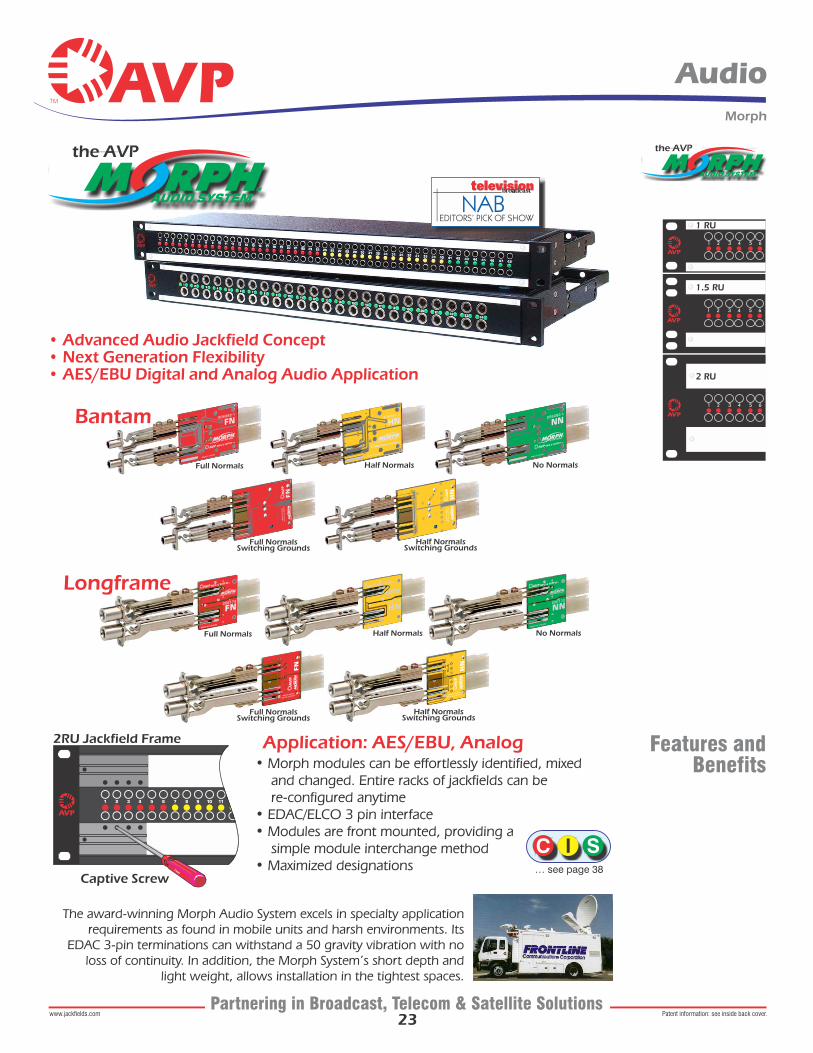
AssemblyDrawing
Keep an inventory of Morph Modules and empty Morph frames to allow custom jackfield assembly or re-configuration in minutes! Morph modules fit 1, 1.5 & 2 Rack Unit frames.
Circuit Indicator Full Normals Half Normals No Normals
Captive Jack Screws are locked in the panel • easy 'front-of-the-rack' assembly and re-arrangement • no more frantic searches for dropped screws. Screw holes are hidden by paper insert and clear window • Use the same 2.5mm hex wrench as used with AVP video panels
Maximized Designations
Gold PlatedContact Terminals
Mating Connector Kit Included
Module slides in and out of the rear of the panel.
Assembly Drawing
19.00”/ 483mm
Top View
*Easy-Tie Pivoting Cable Bar
10.0
0”/ 2
55m
m
5.25
”/ 1
35m
m
the AVP
24
Morph
Audio
MatingConnector Kit
Tooling
EDAC Hand Crimp ToolAVP Model AT-EHCT
EDAC Insertion ToolAVP Model AT-EIT
Each Morph Jackfield is shipped complete with its crimp-pin mating connector kit and a captive hex driver.
EDAC Ejection ToolAVP Model AT-EET
(See ordering information for more details)
Patent information: see inside back cover.www.jackfields.comPartnering in Broadcast, Telecom & Satellite Solutions
MK224P-E03CMK226P-E03CMK224P-E03SMK226P-E03S
EDAC 3Pin Primaries Kit for 2x24 Patchbay, CrimpEDAC 3Pin Primaries Kit for 2x26 Patchbay, CrimpEDAC 3Pin Primaries Kit for 2x24 Patchbay, SolderEDAC 3Pin Primaries Kit for 2x26 Patchbay, Solder
Mating Connector Kits, below, do not include the captive hex driver. Please contact AVP if required.
• Contacts and Crimp Tools Accommodate from 28 AWG to 18 AWG, Solid or Stranded Conductor Diameters from .012" (0.30) to .049" (1.25) and an Insulation Diameter up to .074" (1.88)• Multiple Smaller Gauge Wires may be Crimped Together• Crimp Resistance from 0.5 Milliohms (18 AWG) to 1.5 Milliohms (28AWG)
CRIMP CHARACTERISTICS
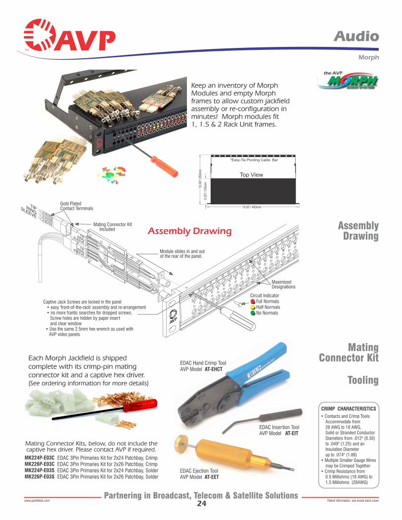
LongframeOrdering
Information
Complete JackfieldsAM-A224E1-L-FN-E03AM-A224E1-L-HN-E03AM-A224E1-L-NN-E03
Individual ComponentsAM-A-FN-E03AM-A-HN-E03AM-A-NN-E03AM-A224E1-ZMK224P-E03CMK226P-E03CMK224P-E03SMK226P-E03S
1RU, 2x24 Frame with 24 Dual Full Normal Modules (AM-A-FN-E03) installed , Mating Connector Kit1RU, 2x24 Frame with 24 Dual Half Normal Modules (AM-A-HN-E03) installed , Mating Connector Kit1RU, 2x24 Frame with 24 Dual No Normal Modules (AM-A-NN-E03) installed , Mating Connector Kit
Dual Longframe Module, Full Normals, EDAC 3 pin termination Dual Longframe Module, Half Normals, EDAC 3 pin termination Dual Longframe Module, No Normals, EDAC 3 pin termination1RU, 2x24 Frame, empty EDAC 3Pin Primaries Kit for 2x24 Patchbay, CrimpEDAC 3Pin Primaries Kit for 2x26 Patchbay, CrimpEDAC 3Pin Primaries Kit for 2x24 Patchbay, SolderEDAC 3Pin Primaries Kit for 2x26 Patchbay, Solder
Popular Models and Components
Model Description
M E03A 2 E L
Installed Module Type
Options, add to end of Model Number
FNHNNNFNSGHNSG
-KZ-KS-SGVM
Full NormalsHalf NormalsNo NormalsFull Normals Switching GroundsHalf Normal Switching Grounds
No Mating Connector KitSolder Mating Connector KitStrapped grounds at each vertical jack pair
the AVP
Number of Dual Modules
Series
Panel Height
2426
AT
1152
24 Modules26 Modules
Mosaic Mosaic (Black CIS)
1 Rack Unit 1.75”, 44mm1.5 Rack Unit 2.62”, 66mm2 Rack Unit 3.50”, 89mm
25
Morph
Audio
LongframeAudio
Patchcords1’
1.5’
2’
3’
4’
6’
10’
300mm
450mm
600mm
900mm
1200mm
1800mm
3.05m
LPC-1-BLACK
LPC-1.5-BLACK
LPC-2-BLACK
LPC-3-BLACK
LPC-4-BLACK
LPC-6-BLACK
LPC-10-BLACK
LPC-1-RED
LPC-1.5-RED
LPC-2-RED
LPC-3-RED
LPC-4-RED
LPC-6-RED
LPC-10-RED
LPC-1-GREEN
LPC-1.5-GREEN
LPC-2-GREEN
LPC-3-GREEN
LPC-4-GREEN
LPC-6-GREEN
LPC-10-GREEN
LPC-1-BLUE
LPC-1.5-BLUE
LPC-2-BLUE
LPC-3-BLUE
LPC-4-BLUE
LPC-6-BLUE
LPC-10-BLUE
LPC-1-YELLOW
LPC-1.5-YELLOW
LPC-2-YELLOW
LPC-3-YELLOW
LPC-4-YELLOW
LPC-6-YELLOW
LPC-10-YELLOW
Longframe Patchcords
110 Ohm AES/EBU Digital and Analog Audio Application ... more patchcords available on page 56
Patent information: see inside back cover.www.jackfields.comPartnering in Broadcast, Telecom & Satellite Solutions
Designation Layouts... www.jackfields.com/support
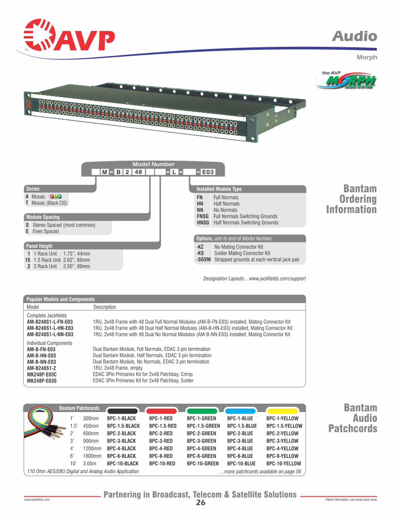
BantamOrdering
Information
Complete JackfieldsAM-B248S1-L-FN-E03AM-B248S1-L-HN-E03AM-B248S1-L-NN-E03
Individual ComponentsAM-B-FN-E03AM-B-HN-E03AM-B-NN-E03AM-B248S1-ZMK248P-E03CMK248P-E03S
1RU, 2x48 Frame with 48 Dual Full Normal Modules (AM-B-FN-E03) installed, Mating Connector Kit1RU, 2x48 Frame with 48 Dual Half Normal Modules (AM-B-HN-E03) installed, Mating Connector Kit1RU, 2x48 Frame with 48 Dual No Normal Modules (AM-B-NN-E03) installed, Mating Connector Kit
Dual Bantam Module, Full Normals, EDAC 3 pin terminationDual Bantam Module, Half Normals, EDAC 3 pin terminationDual Bantam Module, No Normals, EDAC 3 pin termination1RU, 2x48 Frame, emptyEDAC 3Pin Primaries Kit for 2x48 Patchbay, CrimpEDAC 3Pin Primaries Kit for 2x48 Patchbay, Solder
Model Description
M 48 E03B 2 L
Installed Module Type
FNHNNNFNSGHNSG
Full NormalsHalf NormalsNo NormalsFull Normals Switching GroundsHalf Normals Switching Grounds
Popular Models and Components
the AVP
Series
Module Spacing
Panel Height
AT
SE
1152
Mosaic Mosaic (Black CIS)
Stereo Spaced (most common)Even Spaced
1 Rack Unit 1.75”, 44mm1.5 Rack Unit 2.62”, 66mm2 Rack Unit 3.50”, 89mm
Options, add to end of Model Number
-KZ-KS-SGVM
No Mating Connector KitSolder Mating Connector KitStrapped grounds at each vertical jack pair
26
Morph
Audio
…more patchcords available on page 56
BantamAudio
Patchcords1’
1.5’
2’
3’
4’
6’
10’
300mm
450mm
600mm
900mm
1200mm
1800mm
3.05m
BPC-1-BLACK
BPC-1.5-BLACK
BPC-2-BLACK
BPC-3-BLACK
BPC-4-BLACK
BPC-6-BLACK
BPC-10-BLACK
BPC-1-RED
BPC-1.5-RED
BPC-2-RED
BPC-3-RED
BPC-4-RED
BPC-6-RED
BPC-10-RED
BPC-1-GREEN
BPC-1.5-GREEN
BPC-2-GREEN
BPC-3-GREEN
BPC-4-GREEN
BPC-6-GREEN
BPC-10-GREEN
BPC-1-BLUE
BPC-1.5-BLUE
BPC-2-BLUE
BPC-3-BLUE
BPC-4-BLUE
BPC-6-BLUE
BPC-10-BLUE
BPC-1-YELLOW
BPC-1.5-YELLOW
BPC-2-YELLOW
BPC-3-YELLOW
BPC-4-YELLOW
BPC-6-YELLOW
BPC-10-YELLOW
Bantam Patchcords
110 Ohm AES/EBU Digital and Analog Audio Application
Patent information: see inside back cover.www.jackfields.comPartnering in Broadcast, Telecom & Satellite Solutions
Designation Layouts... www.jackfields.com/support
27
Audio
Patent information: see inside back cover.www.jackfields.comPartnering in Broadcast, Telecom & Satellite Solutions
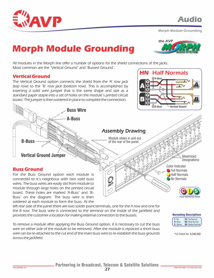
Normaling Descriptions
Circuit Identification System
TN: Tip NormalRN: Ring NormalSN: Sleeve Normal
T: TipR: RingS: Sleeve
Vertical GroundThe Vertical Ground option connects the shield from the ‘A’ row jack (top row) to the ‘B’ row jack (bottom row). This is accomplished by inserting a solid wire jumper that is the same shape and size as a standard paper staple into a set of holes on the module’s printed circuit board. The jumper is then soldered in place to complete the connection.
Buss GroundFor the Buss Ground option each module is connected to it’s neighbour with two solid buss wires. The buss wires are easily slid from module to module through large holes on the printed circuit board. These holes are marked ‘A-Buss’ and ‘B-Buss’ on the diagram. The buss wire is then soldered at each module to form the buss. At the left rear side of the panel there are two solder point terminals, one for the A row and one for the B row. The buss wire is connected to the terminal on the inside of the jackfield and provides the customer a location for making external connection to the busses.
To remove a module after applying the Buss Ground option, it is necessary to cut the buss wire on either side of the module to be removed. After the module is replaced a short buss wire can be re-attached to the cut end of the main buss wire to re-establish the buss grounds across the jackfield.
Morph Module Grounding
A
B
HN Half NormalsA-Buss
Vertical GroundB-Buss
Color Indicator Full Normals Half Normals No Normals
Maximized Designations
A-Buss
Buss Wire
B-Buss
Vertical Ground Jumper
Module slides in and out of the rear of the panel.
Assembly Drawing
the AVP
*US Patent No. 6,540,562
All modules in the Morph line offer a number of options for the shield connections of the jacks. Most common are the ‘Vertical Ground’ and ‘Bussed Ground’.
Morph Module Grounding
28
Midsize Video, Bantam Audio & Data Combo
Audio/Video/Data
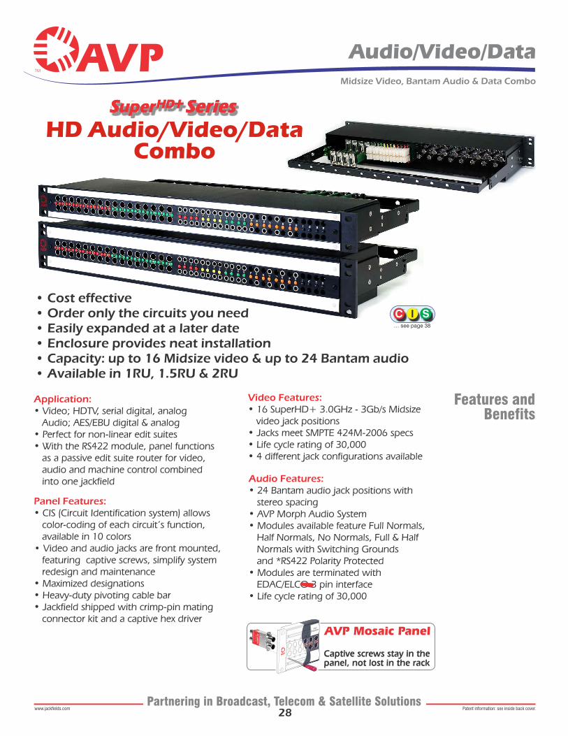
• Cost effective• Order only the circuits you need• Easily expanded at a later date• Enclosure provides neat installation• Capacity: up to 16 Midsize video & up to 24 Bantam audio• Available in 1RU, 1.5RU & 2RU
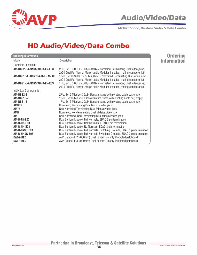
HD Audio/Video/Data Combo
Audio Features: • 24 Bantam audio jack positions with stereo spacing• AVP Morph Audio System• Modules available feature Full Normals, Half Normals, No Normals, Full & Half Normals with Switching Grounds and *RS422 Polarity Protected • Modules are terminated with EDAC/ELCO 3 pin interface• Life cycle rating of 30,000
Video Features: • 16 SuperHD+ 3.0GHz - 3Gb/s Midsize video jack positions• Jacks meet SMPTE 424M-2006 specs• Life cycle rating of 30,000• 4 different jack configurations available
Panel Features: • CIS (Circuit Identification system) allows color-coding of each circuit’s function, available in 10 colors• Video and audio jacks are front mounted, featuring captive screws, simplify system redesign and maintenance• Maximized designations• Heavy-duty pivoting cable bar• Jackfield shipped with crimp-pin mating connector kit and a captive hex driver
Application: • Video; HDTV, serial digital, analog Audio; AES/EBU digital & analog• Perfect for non-linear edit suites• With the RS422 module, panel functions as a passive edit suite router for video, audio and machine control combined into one jackfield
Features andBenefits
… see page 38
AVP Mosaic Panel
Captive screws stay in thepanel, not lost in the rack
Patent information: see inside back cover.www.jackfields.comPartnering in Broadcast, Telecom & Satellite Solutions
29
Audio/Video/Data
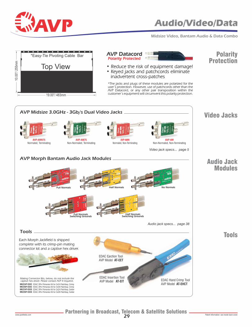
AVP Midsize 3.0GHz - 3Gb/s Dual Video Jacks
AVP Morph Bantam Audio Jack Modules
Tools
AVP-AMNNormaled, Non-Terminating
AVP-AMNon-Normaled, Non-Terminating
AVP-AM75Non-Normaled, Terminating
AVP-AMN75Normaled, Terminating
Full Normals
Full NormalsSwitching Grounds
Half Normals
Half NormalsSwitching Grounds
No Normals
Video Jacks
Audio JackModules
Video jack specs... page 5
Audio jack specs... page 38
Midsize Video, Bantam Audio & Data Combo
Patent information: see inside back cover.www.jackfields.comPartnering in Broadcast, Telecom & Satellite Solutions
Tools
PolarityProtection
Each Morph Jackfield is shipped complete with its crimp-pin mating connector kit and a captive hex driver.
EDAC Hand Crimp ToolAVP Model AT-EHCT
19.00”/ 483mm
Top View
*Easy-Tie Pivoting Cable Bar
10.0
0”/ 2
55m
m
EDAC Insertion ToolAVP Model AT-EIT
EDAC Ejection ToolAVP Model AT-EET
Polarity Protected
• Reduce the risk of equipment damage! • Keyed jacks and patchcords eliminate inadvertent cross-patches *The jacks and plugs of these modules are polarized for the user’s protection. However, use of patchcords other than the AVP Datacord, or any other pair transposition within the customer’s equipment will circumvent this polarity protection.
MK224P-E03CMK226P-E03CMK224P-E03SMK226P-E03S
EDAC 3Pin Primaries Kit for 2x24 Patchbay, CrimpEDAC 3Pin Primaries Kit for 2x26 Patchbay, CrimpEDAC 3Pin Primaries Kit for 2x24 Patchbay, SolderEDAC 3Pin Primaries Kit for 2x26 Patchbay, Solder
Mating Connector Kits, below, do not include the captive hex driver. Please contact AVP if required.
30
Audio/Video/Data Midsize Video, Bantam Audio & Data Combo
Patent information: see inside back cover.www.jackfields.comPartnering in Broadcast, Telecom & Satellite Solutions
AM-DBS2-L-AMN75/AM-B-FN-E03
AM-DBS15-L-AMN75/AM-B-FN-E03
AM-DBS1-L-AMN75/AM-B-FN-E03
AM-DBS2-ZAM-DBS15-ZAM-DBS1-ZAMN75AM75AMNAMAM-B-FN-E03AM-B-HN-E03AM-B-NN-E03AM-B-FNSG-E03AM-B-HNSG-E03DAT-2-REDDAT-3-RED
2RU, 2x16 3.0GHz - 3Gb/s AMN75 Normaled, Terminating Dual video jacks, 2x24 Dual Full Normal Morph audio Modules installed, mating connector kit1.5RU, 2x16 3.0GHz - 3Gb/s AMN75 Normaled, Terminating Dual video jacks, 2x24 Dual Full Normal Morph audio Modules installed, mating connector kit1RU, 2x16 3.0GHz - 3Gb/s AMN75 Normaled, Terminating Dual video jacks, 2x24 Dual Full Normal Morph audio Modules installed, mating connector kit
2RU, 2x16 Midsize & 2x24 Bantam frame with pivoting cable bar, empty1.5RU, 2x16 Midsize & 2x24 Bantam frame with pivoting cable bar, empty 1RU, 2x16 Midsize & 2x24 Bantam frame with pivoting cable bar, empty Normaled, Terminating Dual Midsize video jackNon-Normaled,Terminating Dual Midsize video jackNormaled, Non-Terminating Dual Midsize video jackNon-Normaled, Non-Terminating Dual Midsize video jackDual Bantam Module, Full Normals, EDAC 3 pin terminationDual Bantam Module, Half Normals, EDAC 3 pin terminationDual Bantam Module, No Normals, EDAC 3 pin terminationDual Bantam Module, Full Normals Switching Grounds, EDAC 3 pin terminationDual Bantam Module, Full Normals Switching Grounds, EDAC 3 pin terminationAVP Datacord, 2’ (600mm) Dual Bantam Polarity Protected patchcordAVP Datacord, 3’ (900mm) Dual Bantam Polarity Protected patchcord
Model Description
Ordering Information
Complete Jackfields
Individual Components
OrderingInformation
HD Audio/Video/Data Combo
31
Programmable Audio
Audio
Patent information: see inside back cover.www.jackfields.comPartnering in Broadcast, Telecom & Satellite Solutions
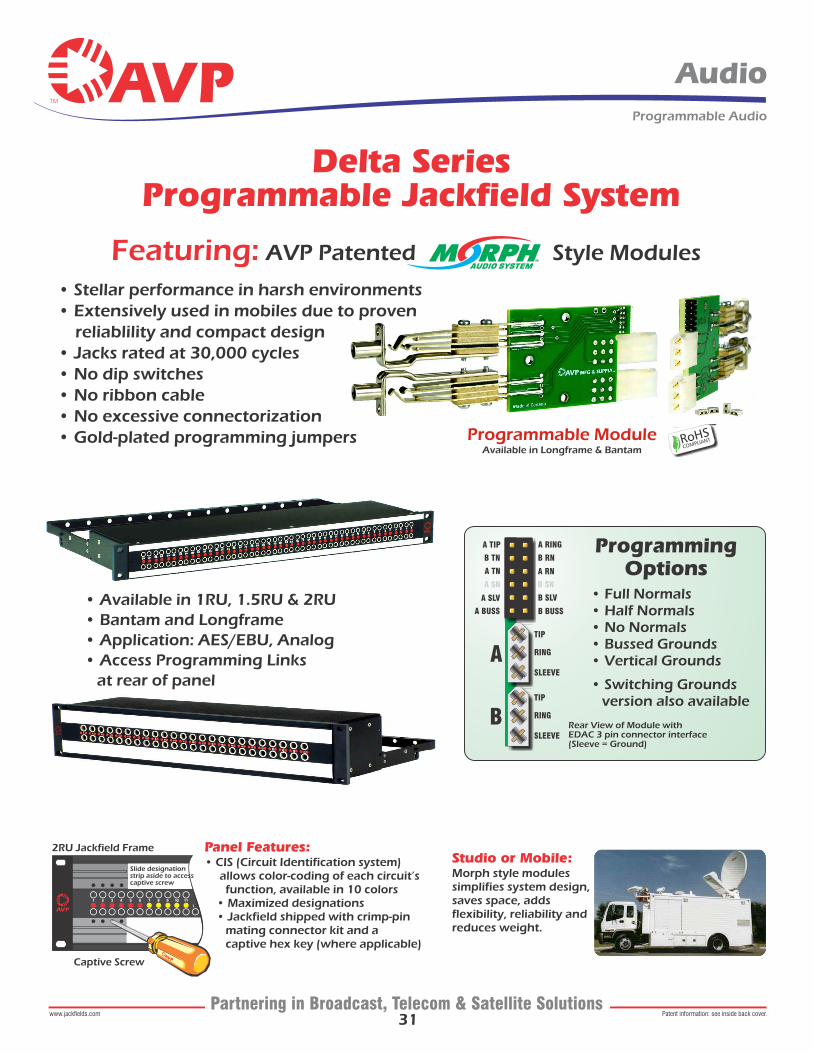
Delta Series Programmable Jackfield System
Captive Screw
2RU Jackfield Frame
Slide designation strip aside to access captive screw
Panel Features: • CIS (Circuit Identification system) allows color-coding of each circuit’s function, available in 10 colors • Maximized designations • Jackfield shipped with crimp-pin mating connector kit and a captive hex key (where applicable)
Studio or Mobile: Morph style modulessimplifies system design, saves space, adds flexibility, reliability and reduces weight.
Programmable ModuleAvailable in Longframe & Bantam
Featuring: AVP Patented Style Modules
• Available in 1RU, 1.5RU & 2RU• Bantam and Longframe• Application: AES/EBU, Analog• Access Programming Links at rear of panel
• Stellar performance in harsh environments• Extensively used in mobiles due to proven reliablility and compact design• Jacks rated at 30,000 cycles• No dip switches• No ribbon cable • No excessive connectorization• Gold-plated programming jumpers
Rear View of Module with EDAC 3 pin connector interface(Sleeve = Ground)
ProgrammingOptions
• Full Normals • Half Normals • No Normals • Bussed Grounds • Vertical Grounds
• Switching Grounds version also available
A BUSS B BUSS
A SLV B SLV
A SN
A
B
B SN
A TN A RN
B TN B RN
A TIP A RING
TIP
TIP
RING
RING
SLEEVE
SLEEVE