Embed Size (px)
Citation preview

VSX-21AUDIO/VIDEO
MULTI-CHANNEL RECEIVER
Operating Instructions

2<ARB7181>
Information to UserAlteration or modifications carried out without appropriate authorization may invalidate the user's right to operate the equipment.
IMPORTANT
The lightning flash with arrowhead symbol, withinan equilateral triangle, is intended to alert theuser to the presence of uninsulated "dangerousvoltage" within the product's enclosure that maybe of sufficient magnitude to constitute a risk ofelectric shock to persons.
The exclamation point within an equilateraltriangle is intended to alert the user to the presenceof important operating and maintenance(servicing) instructions in the literatureaccompanying the appliance.
CAUTION:TO PREVENT THE RISK OF ELECTRIC SHOCK, DONOT REMOVE COVER (OR BACK). NO USER-SER-VICEABLE PARTS INSIDE. REFER SERVICING TOQUALIFIED SERVICE PERSONNEL.
RISK OF ELECTRIC SHOCKDO NOT OPEN
CAUTION
This equipment has been tested and found to comply with the limits for a Class B digital device, pursuant to Part 15 of the FCC Rules.These limits are designed to provide reasonable protection against harmful interference in a residential installation. This equipmentgenerates, uses, and can radiate radio frequency energy and, if not installed and used in accordance with the instructions, may causeharmful interference to radio communications. However, there is no guarantee that interference will not occur in a particularinstallation. If this equipment does cause harmful interference to radio or television reception, which can be determined by turningthe equipment off and on, the user is encouraged to try to correct the interference by one or more of the following measures:
– Reorient or relocate the receiving antenna.– Increase the separation between the equipment and receiver.– Connect the equipment into an outlet on a circuit different from that to which the receiver is connected.– Consult the dealer or an experienced radio/TV technician for help.
Thank you for buying this Pioneer product.Please read through these operating instructions so you will knowhow to operate your model properly. After you have finishedreading the instructions, put them away in a safe place for futurereference.
THE POWER SWITCH IS SECONDARY CONNECTED ANDTHEREFORE DOES NOT SEPARATE THE UNIT FROM MAINSPOWER IN THE STANDBY POSITION.
IMPORTANT NOTICEThe serial number for this equipment is located on the rear panel.
Please write this serial number on your enclosed warranty card
and keep it in a secure area. This is for your security.
WARNING: TO PREVENT FIRE OR SHOCK HAZARD, DO NOT
EXPOSE THIS APPLIANCE TO RAIN OR MOISTURE.
[For Canadian model]CAUTION: TO PREVENT ELECTRIC SHOCK DO NOT USE THIS
(POLARIZED) PLUG WITH AN EXTENSION CORD, RECEPTACLE
OR OTHER OUTLET UNLESS THE BLADES CAN BE FULLY
INSERTED TO PREVENT BLADE EXPOSURE.
ATTENTION: POUR PREVENIR LES CHOCS ELECTRIQUES NE
PAS UTIL ISER CETTE F ICHE POLARISEE AVEC UN
PROLONGATEUR, UNE PRISE DE COURANT OU UNE AUTRE
SORTIE DE COURANT, SAUF SI LES LAMES PEUVENT ETRE
INSEREES A FOND SANS EN LAISSER AUCUNE PARTIE A
DECOUVERT.

SE
T U
PO
PE
RA
TIO
N
3<ARB7181>
READ INSTRUCTIONS — All the safety and operatinginstructions should be read before the product isoperated.
RETAIN INSTRUCTIONS — The safety and operatinginstructions should be retained for future reference.
HEED WARNINGS — All warnings on the product andin the operating instructions should be adhered to.
FOLLOW INSTRUCTIONS — All operating and useinstructions should be followed.
CLEANING — Unplug this product from the wall outletbefore cleaning. The product should be cleaned onlywith a polishing cloth or a soft dry cloth. Never cleanwith furniture wax, benzine, insecticides or othervolatile liquids since they may corrode the cabinet.
ATTACHMENTS — Do not use attachments notrecommended by the product manufacturer as theymay cause hazards.
WATER AND MOISTURE — Do not use this productnear water — for example, near a bathtub, washbowl, kitchen sink, or laundry tub; in a wet basement;or near a swimming pool; and the like.
ACCESSORIES — Do not place this product on anunstable cart, stand, tripod, bracket, or table. Theproduct may fall, causing serious injury to a child oradult, and serious damage to the product. Use onlywith a cart, stand, tripod, bracket, or tablerecommended by the manufacturer, or sold withthe product. Any mounting of the product shouldfollow the manufacturer’s instructions, and shoulduse a mounting accessory recommended by themanufacturer.
CART — A product and cart combination should bemoved with care. Quick stops, excessive force, anduneven surfaces may cause the product and cartcombination to overturn.
GROUNDING OR POLARIZATION
¶ If this product is equipped with a polarized alternatingcurrent line plug (a plug having one blade wider thanthe other), it will fit into the outlet only one way. Thisis a safety feature. If you are unable to insert the plugfully into the outlet, try reversing the plug. If the plugshould still fail to fit, contact your electrician toreplace your obsolete outlet. Do not defeat thesafety purpose of the polarized plug.
¶ If this product is equipped with a three-wiregrounding type plug, a plug having a third (grounding)pin, it will only fit into a grounding type power outlet.This is a safety feature. If you are unable to insert theplug into the outlet, contact your electrician toreplace your obsolete outlet. Do not defeat thesafety purpose of the grounding type plug.
POWER-CORD PROTECTION — Power-supply cordsshould be routed so that they are not likely to bewalked on or pinched by items placed upon oragainst them, paying particular attention to cords atplugs, convenience receptacles, and the point wherethey exit from the product.
OUTDOOR ANTENNA GROUNDING — If an outsideantenna or cable system is connected to the product,be sure the antenna or cable system is grounded soas to provide some protection against voltage surgesand built-up static charges. Article 810 of the NationalElectrical Code, ANSI/NFPA 70, provides informationwith regard to proper grounding of the mast andsupporting structure, grounding of the lead-in wireto an antenna discharge unit, size of groundingconductors, location of antenna-discharge unit,connection to grounding electrodes, andrequirements for the grounding electrode. See FigureA.
LIGHTNING — For added protection for this productduring a lightning storm, or when it is left unattendedand unused for long periods of time, unplug it fromthe wall outlet and disconnect the antenna or cablesystem. This will prevent damage to the productdue to lightning and power-line surges.
POWER LINES — An outside antenna system shouldnot be located in the vicinity of overhead power linesor other electric light or power circuits, or where itcan fall into such power lines or circuits. Wheninstalling an outside antenna system, extreme careshould be taken to keep from touching such powerlines or circuits as contact with them might be fatal.
OVERLOADING — Do not overload wall outlets,extension cords, or integral convenience receptaclesas this can result in a risk of fire or electric shock.
OBJECT AND LIQUID ENTRY — Never push objects ofany kind into this product through openings as theymay touch dangerous voltage points or short-outparts that could result in a fire or electric shock.Never spill liquid of any kind on the product.
SERVICING — Do not attempt to service this productyourself as opening or removing covers may exposeyou to dangerous voltage or other hazards. Refer allservicing to qualified service personnel.
DAMAGE REQUIRING SERVICE — Unplug this productfrom the wall outlet and refer servicing to qualifiedservice personnel under the following conditions:
¶ When the power-supply cord or plug is damaged.¶ If liquid has been spilled, or objects have fallen into
the product.¶ If the product has been exposed to rain or water.¶ If the product does not operate normally by following
the operating instructions. Adjust only those controlsthat are covered by the operating instructions as animproper adjustment of other controls may result indamage and will often require extensive work by aqualified technician to restore the product to itsnormal operation.
¶ If the product has been dropped or damaged in anyway.
¶ When the product exhibits a distinct change inperformance — this indicates a need for service.
REPLACEMENT PARTS — When replacement partsare required, be sure the service technician has usedreplacement parts specified by the manufacturer orhave the same characteristics as the original part.Unauthorized substitutions may result in fire, electricshock, or other hazards.
SAFETY CHECK — Upon completion of any service orrepairs to this product, ask the service technician toperform safety checks to determine that the productis in proper operating condition.
WALL OR CEILING MOUNTING — The product shouldnot be mounted to a wall or ceiling.
HEAT — The product should be situated away from heatsources such as radiators, heat registers, stoves, orother products (including amplifiers) that produceheat.
IMPORTANT SAFETY INSTRUCTIONS
GROUNDCLAMP
ANTENNADISCHARGE UNIT(NEC SECTION 810-20)
GROUNDING CONDUCTORS(NEC SECTION 810-21)
GROUND CLAMPS
POWER SERVICE GROUNDINGELECTRODE SYSTEM(NEC ART 250, PART H)
ELECTRICSERVICEEQUIPMENT
Fig. A
ANTENNALEAD INWIRE
NEC — NATIONAL ELECTRICAL CODE
VENTILATION — Slots and openings in the cabinet areprovided for ventilation and to ensure reliableoperation of the product and to protect it fromoverheating, and these openings must not beblocked or covered. The openings should never beblocked by placing the product on a bed, sofa, rug,or other similar surface. This product should not beplaced in a built-in installation such as a bookcase orrack unless proper ventilation is provided or themanufacturer’s instructions have been adhered to.
POWER SOURCES — This product should be operatedonly from the type of power source indicated on themarking label. If you are not sure of the type ofpower supply to your home, consult your productdealer or local power company.
LOCATION – The appliance should be installed in astable location.
NONUSE PERIODS – The power cord of the applianceshould be unplugged from the outlet when leftunused for a long period of time.
4<ARB7181>
Features
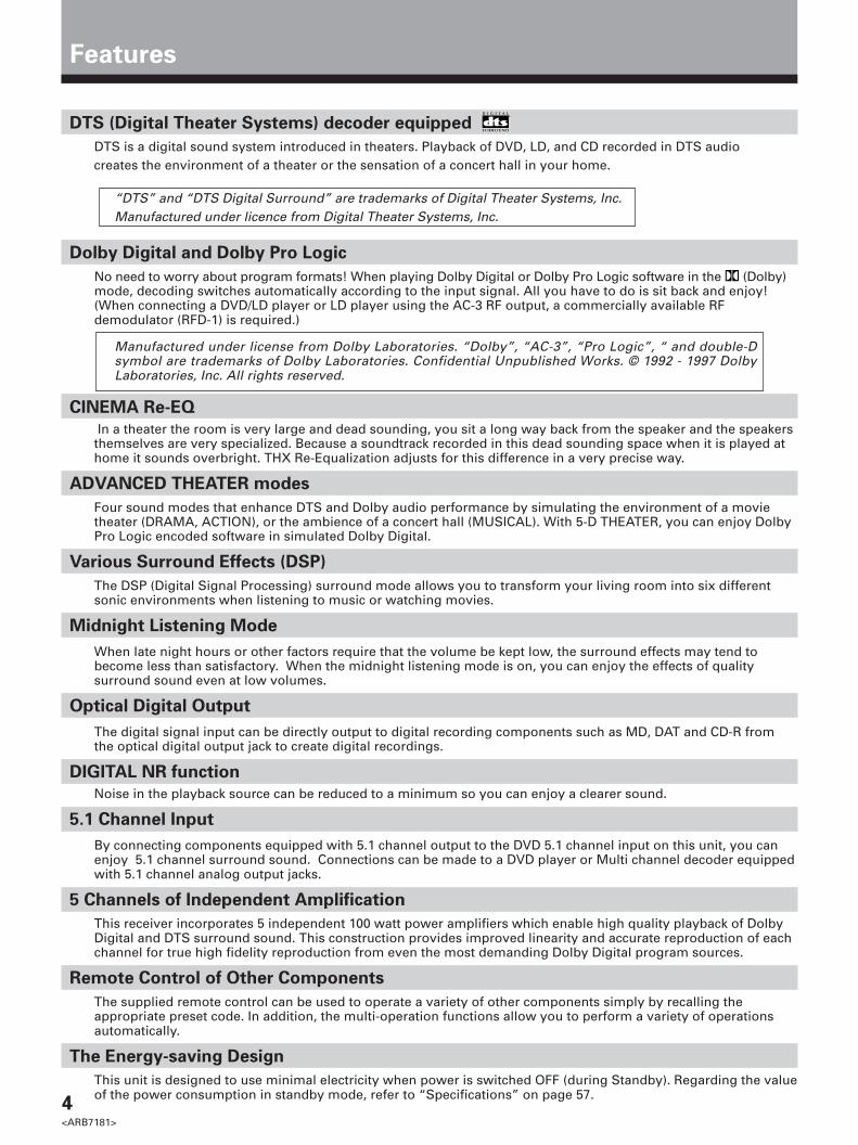
DTS (Digital Theater Systems) decoder equipped R
DTS is a digital sound system introduced in theaters. Playback of DVD, LD, and CD recorded in DTS audiocreates the environment of a theater or the sensation of a concert hall in your home.
“DTS” and “DTS Digital Surround” are trademarks of Digital Theater Systems, Inc.Manufactured under licence from Digital Theater Systems, Inc.
Dolby Digital and Dolby Pro Logic
No need to worry about program formats! When playing Dolby Digital or Dolby Pro Logic software in the (Dolby)mode, decoding switches automatically according to the input signal. All you have to do is sit back and enjoy!(When connecting a DVD/LD player or LD player using the AC-3 RF output, a commercially available RFdemodulator (RFD-1) is required.)
Manufactured under license from Dolby Laboratories. “Dolby”, “AC-3”, “Pro Logic”, “ and double-Dsymbol are trademarks of Dolby Laboratories. Confidential Unpublished Works. © 1992 - 1997 DolbyLaboratories, Inc. All rights reserved.
CINEMA Re-EQ
In a theater the room is very large and dead sounding, you sit a long way back from the speaker and the speakersthemselves are very specialized. Because a soundtrack recorded in this dead sounding space when it is played athome it sounds overbright. THX Re-Equalization adjusts for this difference in a very precise way.
ADVANCED THEATER modes
Four sound modes that enhance DTS and Dolby audio performance by simulating the environment of a movietheater (DRAMA, ACTION), or the ambience of a concert hall (MUSICAL). With 5-D THEATER, you can enjoy DolbyPro Logic encoded software in simulated Dolby Digital.
Various Surround Effects (DSP)
The DSP (Digital Signal Processing) surround mode allows you to transform your living room into six differentsonic environments when listening to music or watching movies.
Midnight Listening Mode
When late night hours or other factors require that the volume be kept low, the surround effects may tend tobecome less than satisfactory. When the midnight listening mode is on, you can enjoy the effects of qualitysurround sound even at low volumes.
Optical Digital Output
The digital signal input can be directly output to digital recording components such as MD, DAT and CD-R fromthe optical digital output jack to create digital recordings.
DIGITAL NR function
Noise in the playback source can be reduced to a minimum so you can enjoy a clearer sound.
5.1 Channel Input
By connecting components equipped with 5.1 channel output to the DVD 5.1 channel input on this unit, you canenjoy 5.1 channel surround sound. Connections can be made to a DVD player or Multi channel decoder equippedwith 5.1 channel analog output jacks.
5 Channels of Independent Amplification
This receiver incorporates 5 independent 100 watt power amplifiers which enable high quality playback of DolbyDigital and DTS surround sound. This construction provides improved linearity and accurate reproduction of eachchannel for true high fidelity reproduction from even the most demanding Dolby Digital program sources.
Remote Control of Other Components
The supplied remote control can be used to operate a variety of other components simply by recalling theappropriate preset code. In addition, the multi-operation functions allow you to perform a variety of operationsautomatically.
The Energy-saving Design
This unit is designed to use minimal electricity when power is switched OFF (during Standby). Regarding the valueof the power consumption in standby mode, refer to “Specifications” on page 57.

SE
T U
PO
PE
RA
TIO
N
5<ARB7181>
Table of Contents
Introductory Information............................................................ 6
Checking the Supplied Accessories .......................................................... 6How to Use This Manual ........................................................................... 6Preparing the Remote Control .................................................................. 6Receiver Installation ................................................................................... 7When Making Cable Connections ............................................................. 7
Connections ................................................................................. 8
Antennas ..................................................................................................... 8Audio Components Connections .............................................................. 9Video Components Connections ............................................................ 10Digital Connections .................................................................................. 11DVD 5.1 Channel Connection .................................................................. 12Speakers ................................................................................................... 13
Preparations .............................................................................. 16
Setting Up for Surround Sound .............................................................. 16Setting Up the Remote Control ............................................................... 22Clearing the Remote Control Settings .................................................... 23
Names of Parts and Basic Operations..................................... 24
Display ...................................................................................................... 24Remote Control ........................................................................................ 25Front Panel ................................................................................................ 26
Sound Modes ............................................................................ 28
Switching ANALOG/DIGITAL Signal Input ............................................. 29Playing Sources with Dolby Digital or DTS Sound ............................... 30Selecting a Sound Mode ......................................................................... 31CINEMA Re-EQ playback ......................................................................... 33Listening in MIDNIGHT Listening Mode ................................................ 35
Tuner Operations....................................................................... 36
Automatic and Manual Tuning ................................................................ 36Direct Tuning ............................................................................................ 37Memorizing Frequently Tuned Stations ................................................. 38Recalling the Memorized Stations .......................................................... 39
Other Operations ...................................................................... 40
Playback .................................................................................................... 40Recording from Audio Components ...................................................... 42Recording from Video Components ....................................................... 43Remote Controlling Other Components ................................................ 44Background Control of Other Components ........................................... 51
Additional Information ............................................................. 52
Dolby Digital ............................................................................................. 52DTS ............................................................................................................ 53Troubleshooting ....................................................................................... 54Preset Code List ........................................................................................ 56Specifications ........................................................................................... 57

6<ARB7181>
Loading the batteries
Introductory Information
“AA” IEC LR6 batteries x 2FM wire antenna AM loop antenna Remote control unit
Checking the Supplied Accessories
Please check that you have received all of the following accessories with the receiver.
The following marks and symbols are used throughoutthis manual:
Provides additional information, precautions,and advice.
Indicates a blinking button, indicator, ordisplay.
Indicates a steadily lit button, indicator, ordisplay.
How to Use This Manual
When you notice a decrease in the operating range ofthe remote control, replace all batteries with new ones.
AA dry cell batteries ((“AA” IEC LR6)×2)
\
CAUTION!Incorrect use of batteries may result in such hazardsas leakage and bursting. Observe the followingprecautions.• Never use new and old batteries together.• Insert the plus and minus sides of the batteries
properly according to the marks in the battery case.• Batteries with the same shape may have different
voltages. Do not use different batteries together.
Preparing the Remote Control
This manual is divided into two main sections :
SET UPThis section explains how to make the necessaryconnections from the receiver to your other audio andvideo components. Receiver operations described laterin this section under the heading “Preparations” enableyou to set up and customize your home entertainmentcenter.
OPERATIONThis section provides complete information aboutoperation of the receiver and supplied remote control.
memo
When changing the batteries, it isrecommended that you load new batterieswithin five minutes of removing the oldbatteries. If not, the preset codes may becanceled and you will need to set them again.
Power connection
[SWITCHED 100 W (0.8 A) MAX]Switching this receiver on or putting it in standby also switches components connected to the receiver’s AC OUTLETjacks on and off. When connecting components to the AC OUTLET jacks, leave the power switch of the connectedcomponents in the ON position. Total power consumption of connected components should not exceed 100W (0.8 A) .
CAUTION!• To avoid malfunction, overheating, and possible fire risk, do not connect high-wattage appliances such as blow
dryers and irons to the AC OUTLET jacks.• Do not connect a monitor or TV set.
Even if the power consumption of the TV or monitor is within the acceptable limits, when monitors or TV sets areswitched on, they consume a large amount of power and may exceed the capacity of this receiver.
memo
9(
(
9

SE
T U
PO
PE
RA
TIO
N
7<ARB7181>
Introductory Information
Operating other PIONEER components
Receiver Installation
• Do not place objects directly on top of this unit. It will prevent proper heat dispersal.• When installing in a rack, etc., be sure to leave more than 8 inches of space above the receiver.
You can also control PIONEER components(and those made by other manufacturers) bypointing the receiver’s remote control directlyat the respective component. This type ofoperation does not require control cords. Allyou have to do is recall the appropriate presetcode (Refer to “Recalling preset codes” onpage 22).
memo
It is recommended that you place thereceiver to the left of your cassette and/or video decks. This will prevent noisecaused by leakage flux from thetransformer in the receiver. If youexperience noise during playback ofyour cassette and/or video decks, movethem farther away from the receiver.
Receiver
Leave more than 8 inches (20 cm)
When Making Cable Connections
Be careful not to arrange cables in a manner that bendsthe cables over the top of this unit as shown in theillustration. If the cables are brought over this unit, themagnetic field produced by the transformers in this unitmay cause a humming noise to come from the speakers.
Remote Control
Receiver
To CONTROL INterminal of another
PIONEER componentbearing the Î mark.
PIONEER componentbearing the Î mark.
Connecting an optional control cord allows you tooperate other PIONEER components simply by pointingthe receiver’s remote control at the remote sensor on thefront panel of the receiver. The receiver then sends theremote control signals to the other devices via theCONTROL OUT terminal.
Operating range of remote control unit
3030
23 feet(7m)
Remote control may not function properly if :• There are obstacles between the remote
control and the remote sensor.• Direct sunlight or fluorescent light is shining
onto the remote sensor.• The receiver is located near a device
emitting infrared rays.• Operated simultaneously with another
remote control which uses infrared rays.
Point the remote control toward the remote sensor Î onthe front panel of this unit to operate. The remote controlunit will operate the receiver for up to a distance of 23feet (7 m) within 30° angle on each side of the sensor ofthe remote sensor as illustrated below.
OUT INCONTROL
OUT
IN
CONTROL
memo
memo

8<ARB7181>
Connections
Antennas
Using external antennas
7 To improve FM reception
Connect an external FM antenna.
7 To improve AM reception
Connect a 15 to 18 feet (5~6 m) length of vinyl-coated wire to the AMantenna terminal in addition to the supplied AM loop antenna.For the best possible reception, suspend horizontally outdoors.
75 Ω coaxial cable
Outdoor antenna
15~18 feet (5~6 m)
7 AM loop antenna
3/8 in.(10mm)
1 Assemble the antenna. 2 Twist exposed wire strandstogether and insert into AMantenna terminals.
3 Attach to a wall, etc. (if desired)and face toward the directionproviding the best reception.
Indoor antenna
(Vinyl-coated wire)
Connect the FM wire antenna and fully extend (for best reception, attach horizontally alonga window frame, etc.).
AM loop antenna
FM wire antenna
(See below)
HGND
FMUNBAL 75Ω
LOOPANTENNA
AM
HGND
FMUNBAL 75Ω
LOOPANTENNA
AM
/DTS
VIDEOOUT
FMUNBAL
75Ω
OUT IN
IN
CONTROL
LOOPANTENNA
AM
ANTENNA
DIGITAL IN
OPT1
OPT2
OPT3
OPT
DIGITALOUT
COAX
DIGITALIN
PLAY REC
MD/TAPE 1
IN INOUT
PLAY REC
IN IN
IN IN IN
INOUT IN OUT
OUT
CD TAPE 2 MONITOR
TOMONITOR TV
S2
S2 S2 S2 S2 S2 S2
IN IN OUT
IN
IN OUT
OUT
IN OUT
OUT
R
L
R
L
TV/SAT
DVD/LD
VIDEO
DVD 5.1 CHINPUT
SURROUNDL
R CENTER
SUBWOOFER
DVD 5.1 CHFRONT
VCR 1 VCR 2
PCM/
/DTSPCM/
CENTERPREOUT
FRONTPREOUT
SUBWOOFERPREOUT
L
L
L
R
R
R
B
A
SURROUNDSPEAKERS
SORROUNDPREOUT
CENTERSPEAKER
L
R
CAUTION: SEE INSTRUCTION MANUAL
ATTENTION: SEE INSTRUCTION MANUAL
8~16Ω / SPEAKER8~16Ω / SPEAKER
IMPEDANCE SELECTOR
6~LESS THAN 8Ω /SPEAKER6~MOINS DE 8Ω /HAUT- PARLEUR
AC OUTLET
AC 120V 60Hz
FRONT SPEAKERS

SE
T U
PO
PE
RA
TIO
N
9<ARB7181>
Audio Components Connections
Connections
Be sure to switch power to standby and remove the power cord from the wall outlet when you make or changeconnections.
Connect your audio components as shown below. Refer to “Digital Connections” on page 11 when making digitalconnections from your DVD or LD player.
7 Audio cords
Use audio cords (not supplied) to connect the audiocomponents.
Connect red plugs to R (right)and white plugs to L (left).Be sure to insert completely.
L
R
/DTS
VIDEOOUT
FMUNBAL
75Ω
OUT IN
IN
CONTROL
LOOPANTENNA
AM
ANTENNA
DIGITAL IN
OPT1
OPT2
OPT3
OPT
DIGITALOUT
COAX
DIGITALIN
PLAY REC
MD/TAPE 1
IN INOUT
PLAY REC
IN IN
IN IN IN
INOUT IN OUT
OUT
CD TAPE 2 MONITOR
TOMONITOR TV
S2
S2 S2 S2 S2 S2 S2
IN IN OUT
IN
IN OUT
OUT
IN OUT
OUT
R
L
R
L
TV/SAT
DVD/LD
VIDEO
DVD 5.1 CHINPUT
SURROUNDL
R CENTER
SUBWOOFER
DVD 5.1 CHFRONT
VCR 1 VCR 2
PCM/
/DTSPCM/
CENTERPREOUT
FRONTPREOUT
SUBWOOFERPREOUT
L
L
L
R
R
R
B
A
SURROUNDSPEAKERS
SORROUNDPREOUT
CENTERSPEAKER
L
R
CAUTION: SEE INSTRUCTION MANUAL
ATTENTION: SEE INSTRUCTION MANUAL
8~16Ω / SPEAKER8~16Ω / SPEAKER
IMPEDANCE SELECTOR
6~LESS THAN 8Ω /SPEAKER6~MOINS DE 8Ω /HAUT- PARLEUR
AC OUTLET
AC 120V 60Hz
FRONT SPEAKERS
RECPLAY
L
R
L
R
RECPLAY
L
R
L
R
L
OUTPUT
R
» « «»
»
MD recorder
or Cassette deckCD player Cassette deck
*The arrows indicate the direction of the audio signal.
Cassette deck placement
Depending on where the cassette deck is placed, noisemay occur during playback of your cassette deck whichis caused by leakage flux from the transformer in thereceiver. If you experience noise, move the cassette deckfarther away from the receiver.

10<ARB7181>
Connections
Video Components Connections
7 Audio/Video cordsUse audio/video cords (not supplied) to connect thevideo components and a video cord to connect the TVor monitor.
Connect red plugs to R (right),white plugs to L (left), and theyellow plugs to VIDEO.Be sure to insert completely.
Video camera
(etc.)
7 Front
• When connecting components, the receiver should be off and the power cord unpluged.• Connect your video components as shown below. Also, refer to “Digital Connections” on page 11 when making
digital connections from your DVD or LD player.• Although only “S2” is printed on the S-Video jacks on the rear panel, S, S1 and S2 S-video connection can be made
as well.• If your TV monitor or video camera has an S-Video input, clearer picture reproduction is possible by connecting the
receiver to your TV monitor or video camera via the S-Video jack.
memoWhen connecting components equipped withS-video jacks, you can make connections tothis unit using S-video cords (not supplied).However, this unit is not designed to convertthe format of the video signal. Therefore, thesignal from the S2 IN cannot be output fromthe VIDEO OUT and similarly the signal fromthe VIDEO IN cannot be output from the S2OUT.
L R
VIDEO INPUT
VIDEOS-VIDEO L AUDIO R
VIDEO INPUT
/DTS
VIDEOOUT
FMUNBAL
75Ω
OUT IN
IN
CONTROL
LOOPANTENNA
AM
ANTENNA
DIGITAL IN
OPT1
OPT2
OPT3
OPT
DIGITALOUT
COAX
DIGITALIN
PLAY REC
MD/TAPE 1
IN INOUT
PLAY REC
IN IN
IN IN IN
INOUT IN OUT
OUT
CD TAPE 2 MONITOR
TOMONITOR TV
S2
S2 S2 S2 S2 S2 S2
IN IN OUT
IN
IN OUT
OUT
IN OUT
OUT
R
L
R
L
TV/SAT
DVD/LD
VIDEO
DVD 5.1 CHINPUT
SURROUNDL
R CENTER
SUBWOOFER
DVD 5.1 CHFRONT
VCR 1 VCR 2
PCM/
/DTSPCM/
CENTERPREOUT
FRONTPREOUT
SUBWOOFERPREOUT
L
L
L
R
R
R
B
A
SURROUNDSPEAKERS
SORROUNDPREOUT
CENTERSPEAKER
L
R
CAUTION: SEE INSTRUCTION MANUAL
ATTENTION: SEE INSTRUCTION MANUAL
8~16Ω / SPEAKER8~16Ω / SPEAKER
IMPEDANCE SELECTOR
6~LESS THAN 8Ω /SPEAKER6~MOINS DE 8Ω /HAUT- PARLEUR
AC OUTLET
AC 120V 60Hz
FRONT SPEAKERS
V
OUTPUT
L
R
V
OUTPUT
L
R
V
INPUTOUTPUT
V
L
R
L
R
V
INPUTOUTPUT
V
L
R
L
R
INPUT
VIDEO S-VIDEO
L R
» »
» »
« »«
TV
monitor
Video deck (1)
DVD player
(or LD player)
TV tuner
(or satellite tuner)
Video deck (2)
L
R
VIDEO

SE
T U
PO
PE
RA
TIO
N
11<ARB7181>
Digital Connections
Digital components can be connected as shown below. You can select up to four of the following be assigned to thedigital inputs on this unit: DVD/LD, TV/SAT, MD/TAPE, CD, VCR1 (VCR). To assign the digital inputs, refer to “Setting Upfor Surround Sound” on page 16.The digital signal input is output directly to digital recording components from the optical digital output jack.
When playing LD recorded in Dolby Digital
When connecting a DVD/LD player or LD player usingthe AC-3 RF output, a commercially available RFdemodulator (RFD-1) is required. The RF demodulatorchanges the RF signal to a digital signal which is thenprocessed by the receiver through the digital inputjacks. For more details, refer to the instruction manualsupplied with the RFD-1.
The factory setting for each of the digital inputs isdescribed below.
COAX : DVDOPT 1 : CDOPT 2 : MDOPT 3 : TV
memo
7 Digital audio cords/Optical cablesCommercially available digital audio coaxial cords(standard video cords can also be used) or opticalcables (not supplied) are used to connect digitalcomponents to this receiver.When you use optical digital input or output terminals,pull off the caps and insert the plugs. Be sure to insertcompletely.
Digital audio cord
(or standard video cord)Optical cable
/DTS
VIDEOOUT
FMUNBAL
75Ω
OUT IN
IN
CONTROL
LOOPANTENNA
AM
ANTENNA
DIGITAL IN
OPT1
OPT2
OPT3
OPT
DIGITALOUT
COAX
DIGITALIN
PLAY REC
MD/TAPE 1
IN INOUT
PLAY REC
IN IN
IN IN IN
INOUT IN OUT
OUT
CD TAPE 2 MONITOR
TOMONITOR TV
S2
S2 S2 S2 S2 S2 S2
IN IN OUT
IN
IN OUT
OUT
IN OUT
OUT
R
L
R
L
TV/SAT
DVD/LD
VIDEO
DVD 5.1 CHINPUT
SURROUNDL
R CENTER
SUBWOOFER
DVD 5.1 CHFRONT
VCR 1 VCR 2
PCM/
/DTSPCM/
CENTERPREOUT
FRONTPREOUT
SUBWOOFERPREOUT
L
L
L
R
R
R
B
A
SURROUNDSPEAKERS
SORROUNDPREOUT
CENTERSPEAKER
L
R
CAUTION: SEE INSTRUCTION MANUAL
ATTENTION: SEE INSTRUCTION MANUAL
8~16Ω / SPEAKER8~16Ω / SPEAKER
IMPEDANCE SELECTOR
6~LESS THAN 8Ω /SPEAKER6~MOINS DE 8Ω /HAUT- PARLEUR
AC OUTLET
AC 120V 60Hz
FRONT SPEAKERS
OUT
COAX
OUT
DIGITAL
IN
DIGITAL
OUT
DIGITAL
OUT
DIGITAL
»
» »
»
»
CD player DVD player MD recorderTV tuner
(or satellite tuner)
Connections

12<ARB7181>
Connections
DVD 5.1 Channel Connection
DVD and LD discs are often compatible with both 2 channel and 5.1 channel audio output formats. Refer to page 33 formore information on how to switch between the two input methods.Connections can be made from a DVD player or Multi channel decoder equipped with 5.1 analog outputs to the 5.1analog inputs on this unit.
memo
The 5.1 channel input can only be used when DVD/LD is selected.
/DTS
VIDEOOUT
FMUNBAL
75Ω
OUT IN
IN
CONTROL
LOOPANTENNA
AM
ANTENNA
DIGITAL IN
OPT1
OPT2
OPT3
OPT
DIGITALOUT
COAX
DIGITALIN
PLAY REC
MD/TAPE 1
IN INOUT
PLAY REC
IN IN
IN IN IN
INOUT IN OUT
OUT
CD TAPE 2 MONITOR
TOMONITOR TV
S2
S2 S2 S2 S2 S2 S2
IN IN OUT
IN
IN OUT
OUT
IN OUT
OUT
R
L
R
L
TV/SAT
DVD/LD
VIDEO
DVD 5.1 CHINPUT
SURROUNDL
R CENTER
SUBWOOFER
DVD 5.1 CHFRONT
VCR 1 VCR 2
PCM/
/DTSPCM/
CENTERPREOUT
FRONTPREOUT
SUBWOOFERPREOUT
L
L
L
R
R
R
B
A
SURROUNDSPEAKERS
SORROUNDPREOUT
CENTERSPEAKER
L
R
CAUTION: SEE INSTRUCTION MANUAL
ATTENTION: SEE INSTRUCTION MANUAL
8~16Ω / SPEAKER8~16Ω / SPEAKER
IMPEDANCE SELECTOR
6~LESS THAN 8Ω /SPEAKER6~MOINS DE 8Ω /HAUT- PARLEUR
AC OUTLET
AC 120V 60Hz
FRONT SPEAKERS
L
R
SURROUNDOUTPUT
L
R
FRONTOUTPUT
CENTER VIDEOOUT
SUB WOOFER
» » » » »
Components equippedwith 5.1 channel analogueoutput jacks

SE
T U
PO
PE
RA
TIO
N
13<ARB7181>
/DTS
VIDEOOUT
FMUNBAL
75Ω
OUT IN
IN
CONTROL
LOOPANTENNA
AM
ANTENNA
DIGITAL IN
OPT1
OPT2
OPT3
OPT
DIGITALOUT
COAX
DIGITALIN
PLAY REC
MD/TAPE 1
IN INOUT
PLAY REC
IN IN
IN IN IN
INOUT IN OUT
OUT
CD TAPE 2 MONITOR
TOMONITOR TV
S2
S2 S2 S2 S2 S2 S2
IN IN OUT
IN
IN OUT
OUT
IN OUT
OUT
R
L
R
L
TV/SAT
DVD/LD
VIDEO
DVD 5.1 CHINPUT
SURROUNDL
R CENTER
SUBWOOFER
DVD 5.1 CHFRONT
VCR 1 VCR 2
PCM/
/DTSPCM/
CENTERPREOUT
FRONTPREOUT
SUBWOOFERPREOUT
L
L
L
R
R
R
B
A
SURROUNDSPEAKERS
SORROUNDPREOUT
CENTERSPEAKER
L
R
CAUTION: SEE INSTRUCTION MANUAL
ATTENTION: SEE INSTRUCTION MANUAL
8~16Ω / SPEAKER8~16Ω / SPEAKER
IMPEDANCE SELECTOR
6~LESS THAN 8Ω /SPEAKER6~MOINS DE 8Ω /HAUT- PARLEUR
AC OUTLET
AC 120V 60Hz
FRONT SPEAKERS
INPUT
Speakers
Connections
• Use speakers with a nominal impedance of 6 Ω to 16 Ω.• The front speaker B terminal is only used in stereo mode (Not available during DVD 5.1 channel, DSP mode, or Dolby/
DTS mode).• When you use the speaker on your TV as a center speaker, please connect the CENTER PREOUT jack on this unit to
the audio input jack on your TV. In this case, the center speaker shown below is unnecessary. Refer to the instructionmanual supplied with the TV or monitor you are connecting to for more information.
• You can set the configuration of your speaker system, whether the sizes of the speakers are large or small, andwhether or not you have a sub woofer connected. (Refer to pages 16 to 18)
7 Speaker terminals
Front Speakers Surround SpeakersCenter Speaker
Be sure to completeall other connectionsbefore connectingthis unit to the ACpower source.
Powered Sub Woofer
Twist exposed wirestrands together.
Connection methods that differ from the exampleshown in this manual may be available. For moredetails, refer to the instruction manual supplied withthe sub woofer.
TV
(To be used as thecenter speaker)
3/8 in.(10mm)
Turn counter-clockwise to loosen, and insert the wire. Then turnclockwise to tighten.
(To the audio input)
L R C SL SR
Use speakers with nominalimpedance of 6 Ω to 8 Ω or 8 Ω to16 Ω.• When using speakers with
impedance of at least 6 Ω but lessthan 8 Ω, set the IMPEDANCESELECTOR to the “6~LESS THAN8 Ω” position.
• When using 8 Ω to 16 Ω, set theIMPEDANCE SELECTOR to “8~16Ω” position.

14<ARB7181>
Connecting additional amplifiers
To use separate amplifiers to power your speaker, make the connections shown below.
Do not make simultaneous connections to both the CENTER PREOUT jack and the CENTER SPEAKERterminals. (e.g. Do not connect a separate power amplifier to the CENTER PREOUT jack if you have alreadyconnected a center speaker to the CENTER SPEAKER terminal.)
L-Audio
(MONO)
Powered
sub woofer
Connections
(or)
memo
/DTS
VIDEOOUT
FMUNBAL
75Ω
OUT IN
IN
CONTROL
LOOPANTENNA
AM
ANTENNA
DIGITAL IN
OPT1
OPT2
OPT3
OPT
DIGITALOUT
COAX
DIGITALIN
PLAY REC
MD/TAPE 1
IN INOUT
PLAY REC
IN IN
IN IN IN
INOUT IN OUT
OUT
CD TAPE 2 MONITOR
TOMONITOR TV
S2
S2 S2 S2 S2 S2 S2
IN IN OUT
IN
IN OUT
OUT
IN OUT
OUT
R
L
R
L
TV/SAT
DVD/LD
VIDEO
DVD 5.1 CHINPUT
SURROUNDL
R CENTER
SUBWOOFER
DVD 5.1 CHFRONT
VCR 1 VCR 2
PCM/
/DTSPCM/
CENTERPREOUT
FRONTPREOUT
SUBWOOFERPREOUT
L
L
L
R
R
R
B
A
SURROUNDSPEAKERS
SORROUNDPREOUT
CENTERSPEAKER
L
R
CAUTION: SEE INSTRUCTION MANUAL
ATTENTION: SEE INSTRUCTION MANUAL
8~16Ω / SPEAKER8~16Ω / SPEAKER
IMPEDANCE SELECTOR
6~LESS THAN 8Ω /SPEAKER6~MOINS DE 8Ω /HAUT- PARLEUR
AC OUTLET
AC 120V 60Hz
FRONT SPEAKERS
INPUTIN
AUDIO
L
R
IN
AUDIO
L
IN
AUDIO
L
R R
» » »»
PIONEER
projection TV
(for centerchannel)
Amplifier
(for center channel)
Be sure to complete all otherconnections before connectingthis unit to the AC power source.
Amplifier
(for front channel)
Amplifier
(for rear channel)

SE
T U
PO
PE
RA
TIO
N
15<ARB7181>
• Install the left and right front speakers at equal distances from the TV.• When installing speakers near the TV, we recommend using magnetically shielded speakers to prevent
possible interference such as distortion in the color of the TV screen. If you do not have magneticallyshielded speakers and notice discoloration of the TV screen, place the speakers farther away from the TV.
• Install the center speaker above, below the TV so that the sound of the center channel is localized at the TVscreen.
CAUTION:
When installing the center speaker on top of the TV, be sure to secure it with tape or some other suitablemeans.Otherwise, the speaker may fall from the TV due to external shocks such as earthquakes, and it may lead toendangering those nearby or damaging the speaker.
• If possible, install the surround speakers slightly above ear level.• It may be difficult to obtain a cohesive surround effect if the surround speakers are installed farther away
from the listening position than the front and center speakers.
Speaker placement
To achieve the best possible surround sound, install your speakers as shown below. Be sure all speakers are installedsecurely to prevent accidents and improve sound quality.
Connections
SurroundLeft
SurroundRight
ListeningPosition
Front
Left
Front
RightCenter
Sub Woofer
memo

16<ARB7181>
Preparations
1 Press RECEIVER to turn the power on.
The STANDBY indicator goes out.
2 Press RECEIVER.
This switches the remote to the surround setup mode.
3 Press ! or ⁄ to select the mode you desire.
For best results, start with “SPEAKER setting mode” and make yourinitial adjustments in the order described below.
The current settings are displayed automatically.
SPEAKER (Front, Center, Surround) setting mode (page 17)
Use to specify the type of speakers you have connected.SUB WOOFER ON/OFF setting mode (page 18)
Use to specify the sub woofer as on or off.Crossover frequency setting mode (page 18)
Use to determine which frequencies will be sent to the sub woofer or“Large” speakers.LFE attenuator setting mode (page 18)
Use to specify the peak level for the LFE channel and the crossovernetwork for rerouted bass frequencies.Low cut filter ON/OFF setting mode (page 19)
Use to cut the distorted sound from the sub woofer.FRONT speaker distance setting mode (page 19)
Use to specify the distance from your listening position to your front speaker.CENTER speaker distance setting mode (page 19)
Use to specify the distance from your listening position to your center speaker.SURROUND speaker distance setting mode (page 19)
Use to specify the distance from your listening position to your surround speakers.Dynamic range control setting mode (page 20)
Use to compress the dynamic range of the sound track.Coaxial digital input setting (page 20)
Use to specify the input to be assigned to the coaxial digital input.Optical digital input 1 setting (page 20)
Use to specify the input to be assigned to the optical digital input 1.Optical digital input 2 setting (page 20)
Use to specify the input to be assigned to the optical digital input 2.Optical digital input 3 setting (page 21)
Use to specify the input to be assigned to the optical digital input 3.
4 Press % or fi to select the setting you desire.
The setting is entered automatically.
5 Repeat steps 3 and 4 to set other surround modes.
Setting Up for Surround Sound
Be sure to switch the power of this unit on (The STANDBY indicator goes out).
To ensure the best possible surround sound, be sure to complete the following set up operations. This is particularlyimportant when using the (Dolby)/DTS sound mode. You only need to make these settings once (unless you changethe placement of your current speaker system or add new speakers, etc.). Refer to the following pages for detaileddescriptions of the settings available for each mode.
DVD/LD
VCR 1
TV/SAT CD
TUNER
VCR 2 MD/TAPE
TV CONTROL
RECEIVER
DSP MODE
CH.SELECT ATT SIG.SELECT
MIDNIGHT
TEST TONE
AUDIO/VIDEO PRE-PROGRAMMED
REMOTE CONTROL UNIT
2 3
5
0
6
9 +10
TV/VCRCLASS
7 8
41
CHANNEL
MULTI CONTROL
ENTER
VOL VOL
FQ
FQ
+
–
TV FUNC
RECEIVER TV
MUTING
CN.LEVEL EFFECT
FL DIMMER FUNCTION DIRECT
MODE CHECKCOMMANDER
SET UP
Î
MEMU
1
2
3
4
• Press ENTER to to exit the setting mode.• The setting mode is automatically exited
if no operation is performed for 20seconds.
memo

SE
T U
P
17<ARB7181>
Preparations
1 Press % or fi to set the front speaker.
Front speaker (initial setting is “L (Large)”)
• Select “FL” if your speakers will reproduce bass frequencies effectively orif you did not connect a sub woofer.
• Select “FS” to send bass frequencies to the sub woofer. (The center andsurround speakers cannot be set to Large if the front speakers are set toSmall. In this case, all bass frequencies are sent to the sub woofer.)
2 Press % or fi to set the center speaker.
Center speaker (initial setting is “L (Large)”)
• Select “CL” if your speaker will reproduce bass frequencies effectively.• Select “CS” to send bass frequencies to the other speakers or sub woofer.• Select “C∗” if you did not connect a center speaker. In this case, the
center channel is output from the front speakers.
3 Press % or fi to set the surround speaker.
Surround speaker (initial setting is “L (Large)”)
• Select “SL” if your speakers will reproduce bass frequencies effectively.• Select “SS” to send bass frequencies to the other speakers or sub woofer.• Select “S∗” if you did not connect surround speakers. In this case, the
sound of the surround channels is output from the front and centerspeakers.
SPEAKER setting mode
Establishes the size and configuration of the speaker system you have connected.In the display, “F”, “C”, and “S” refer to front, center, and surround speakers respectively. Speaker size is denoted as“L” for large speakers, “S” for small speakers, and “∗” (asterisk) if no speaker is connected.
If the cone size of your speaker is larger than 5 in. (12 cm), please set to Large.
dB
SPSIGNALSELECTANALOG
A
dB
SPSIGNALSELECTANALOG
A
dB
SPSIGNALSELECTANALOG
A
2
22
2
memo
* Press ⁄ to advance to thenext setting, and press ! toreturn to previous setting.

18<ARB7181>
Preparations
SUB WOOFER ON/OFF setting mode
Sets whether the SUB WOOFER is used or not.
• Initial setting is “ON”.• Setting the front speaker size to “Small” in the SPEAKER setting mode automatically locks the sub woofer
in the “ON” position.
Press % or fi to select sub woofer ON or OFF.
memo
Crossover frequency setting mode
Setting speakers to “Small” in “SPEAKER setting mode” sends the respective channels’ bass frequencies to the subwoofer (or “Large” speakers). This function lets you determine which frequencies will be sent to the sub woofer or“Large” speakers.
• Initial setting is “100 Hz”.• If all speakers (front, center, and surround) are set to “Large” in SPEAKER setting mode, crossover
frequency cannot be set. (∗∗∗ appears in the display.)
Press % or fi to specify the crossover frequency for your smallspeakers (100 Hz, 150 Hz or 200 Hz).
100 Hz
Sends bass frequencies below 100 Hz to the sub woofer (or Largespeakers).
150 Hz
Sends bass frequencies below 150 Hz to the sub woofer (or Largespeakers).
200 Hz
Sends bass frequencies below 200 Hz to the sub woofer (or Largespeakers). We recommend setting 200 Hz when only small speakersare used.
memo
LFE attenuator setting mode
Dolby Digital and DTS audio sources include ultra-low bass tones. Set the LFE attenuator as needed to prevent theultra-low bass tones from distorting the sound from the speakers.
• Initial setting is “0 dB”.• When ∞ is selected (∗∗ appears in the display), LFE is not available.
memo
Press % or fi to set the attenuation level (0 dB, 10 dBor ∗∗ dB (∞)).
dB
SPSIGNALSELECTANALOG
A
dB
SPSIGNALSELECTANALOG
A
dB
SPSIGNALSELECTANALOG
A

SE
T U
P
19<ARB7181>
Preparations
Low cut filter ON/OFF setting mode
Turn the low cut filter ON when distorted sound is output through the sub woofer.
• Initial setting is “OFF”.• If the SUB WOOFER is set to “OFF” in the SUB WOOFER ON/OFF setting mode, the low cut filter cannot be
set.• The low cut filter is not effective when DTS signals are input.
Press % or fi to select low cut filter ON or OFF.
memo
CENTER speaker distance setting mode
Normally as the Center speaker is placed directly in front in the listening room, it is closer to the listening position thanthe Front speakers. This means that the sound from the Center speaker will be heard before the Front speakers. Toprevent this, set the Center speaker distance setting to delay the sound from the Center speaker so that the sound fromthe Front and Center speakers will be heard at the same time.
• Initial setting is 10 feet.• When “C∗” is selected in SPEAKER setting mode, the Center distance cannot be set.• One step equals about 1 foot.
Press % or fi to set the distance of the CENTER speaker fromthe main listening position (up to 30 steps).
memo
SURROUND speaker distance setting mode
Use to set the SURROUND speaker distance. Like the CENTER speaker position, the SURROUND speakers may be setin a location closer or farther than the FRONT speakers. Set the distance of the SURROUND speakers accurately to hearsounds coming from both FRONT and SURROUND speakers at the same time.
• Initial setting is 10 feet.• When “S∗” is selected in SPEAKER setting mode, the SURROUND distance cannot be set.• One step equals about 1 foot.
Press % or fi to set the distance of the SURROUND speakerfrom the main listening position (up to 30 steps).
memo
FRONT speaker distance setting mode
Sets the distance from the FRONT speaker to the listening position.
• Initial setting is 10 feet.• One step equals about 1 foot.
dB
SPSIGNALSELECTANALOG
A
memo
Press % or fi to set the distance of the FRONT speaker fromthe main listening position (up to 30 steps).dB
SPSIGNALSELECTANALOG
A
dB
SPSIGNALSELECTANALOG
A
dB
SPSIGNALSELECTANALOG
A

20<ARB7181>
Preparations
Dynamic range control setting mode
Dynamic range is the difference between the loudest and softest sounds in any given signal. The dynamic range controlhelps you play back sounds so the quieter sounds are audible yet the louder sounds don’t get distored. It does this bycompressing the dynamic range. When watching a movie at low volume, setting this function enables low level soundsto be heard more easily.
• Initial setting is “OFF”.• When the volume level is increased, set to OFF.• For listening enjoyment at low volumes, set to “MAX” for maximum dynamic range compression.• Dynamic range control is effective only when a Dolby Digital signal is being played back.
Press % or fi to set the dynamic range control (OFF, MAX orMID).
memo
dB
SPSIGNALSELECTANALOG
A
Coaxial digital input setting
Sets the input component to be assigned to the coaxial digital input jack.
• Initial setting is “DVD”.memo
Press % or fi to select the coaxial digital input (DVD, TV, CD,MD, VCR 1 or OFF).
dB
SPSIGNALSELECTANALOG
A
Optical digital input 1 setting
Sets the input component to be assigned to the optical input 1 jack.
• Initial setting is “CD”.memo
Press % or fi to select the optical digital input 1 (DVD, TV, CD,MD, VCR 1 or OFF).
dB
SPSIGNALSELECTANALOG
A
Optical digital input 2 setting
Sets the input to be assigned to the optical input 2 terminal.
• Initial setting is “MD”.memo
Press % or fi to select the optical digital input 2 (DVD, TV, CD,MD, VCR 1 or OFF).
dB
SPSIGNALSELECTANALOG
A
SE
T U
P
21<ARB7181>
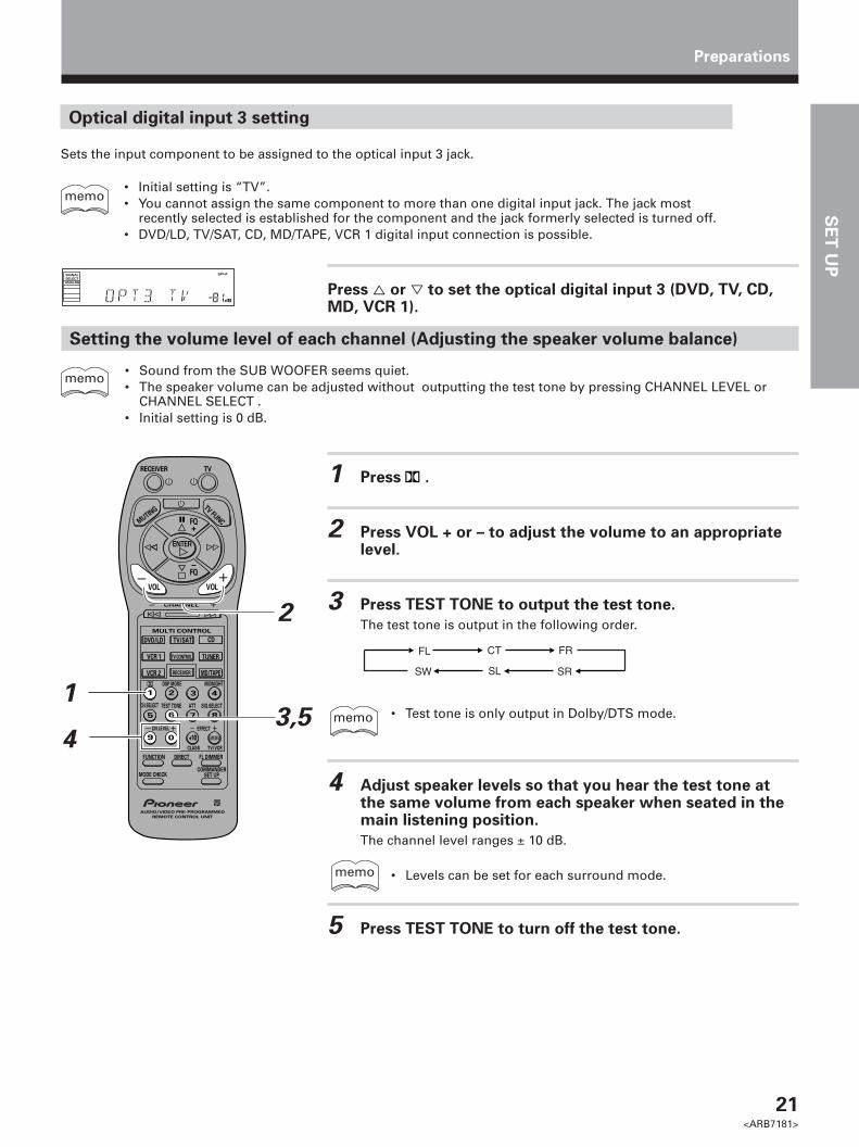
1 Press .
2 Press VOL + or – to adjust the volume to an appropriatelevel.
3 Press TEST TONE to output the test tone.
The test tone is output in the following order.
• Test tone is only output in Dolby/DTS mode.
4 Adjust speaker levels so that you hear the test tone atthe same volume from each speaker when seated in themain listening position.
The channel level ranges ± 10 dB.
• Levels can be set for each surround mode.
5 Press TEST TONE to turn off the test tone.
• Sound from the SUB WOOFER seems quiet.• The speaker volume can be adjusted without outputting the test tone by pressing CHANNEL LEVEL or
CHANNEL SELECT .• Initial setting is 0 dB.
Optical digital input 3 setting
Sets the input component to be assigned to the optical input 3 jack.
• Initial setting is “TV”.• You cannot assign the same component to more than one digital input jack. The jack most
recently selected is established for the component and the jack formerly selected is turned off.• DVD/LD, TV/SAT, CD, MD/TAPE, VCR 1 digital input connection is possible.
Press % or fi to set the optical digital input 3 (DVD, TV, CD,MD, VCR 1).
FL CT FR
SRSLSW
memo
dB
SPSIGNALSELECTANALOG
A
memo
Setting the volume level of each channel (Adjusting the speaker volume balance)
Preparations
DVD/LD
VCR 1
TV/SAT CD
TUNER
VCR 2 MD/TAPE
TV CONTROL
RECEIVER
DSP MODE
CH.SELECT ATT SIG.SELECT
MIDNIGHT
TEST TONE
AUDIO/VIDEO PRE-PROGRAMMED
REMOTE CONTROL UNIT
2 3
5
0
6
9 +10
TV/VCRCLASS
7 8
41
CHANNEL
MULTI CONTROL
ENTER
VOL VOL
FQ
FQ
+
–
TV FUNC
RECEIVER TV
MUTING
CN.LEVEL EFFECT
FL DIMMER FUNCTION DIRECT
MODE CHECKCOMMANDER
SET UP
Î
MEMU
1
2
3,54
memo
memo

22<ARB7181>
1 Press COMMANDER SET UP and 1 at the same time toselect the preset mode.
The MULTI CONTROL buttons on the remote control start to blink.
To cancel the preset mode
Press COMMANDER SET UP.
2 Press the MULTI CONTROL button for the component youwant to control.
Each button can be set to control one of the following components
DVD/LD : DVD/LD player: TV or Satellite tuner
CD : CD player: MD recorder or Tape recorder
VCR 1 : Video deckVCR 2 : Video deck
: TV or Cable TV tuner
The selected button lights steadily and the first manufacturer (andpreset code(s)) appear in the display.
Preparations
Setting Up the Remote Control
In addition to controlling the receiver, the supplied remote control can operate your other components (DVD, MD, VCR,TV, LD, CD, etc.). If your component(s) are listed in the “Preset Code List” on page 56, simply recall the correspondingpreset code.
Recalling preset codes
The following steps show you how to recall preset codes for each MULTI CONTROL button. Once the preset code isassigned, pressing the button will automatically set the remote to operate the respective component.
• Refer to “Preset Code List” on page 56 for the components and manufacturers available.• Refer to “Remote Controlling Other Components” on pages 44 to 50 and “Background Control of Other
Components” on page 51 for detailed explanations on how to operate your other components.
memo
dB
SPSIGNALSELECTANALOG
A
dB
SPSIGNALSELECTANALOG
A
TV/SAT
MD/TAPE
TV CONTROL
DVD/LD
VCR 1
TV/SAT CD
TUNER
VCR 2 MD/TAPE
TV CONTROL
RECEIVER
DSP MODE
CH.SELECT ATT SIG.SELECT
MIDNIGHT
TEST TONE
AUDIO/VIDEO PRE-PROGRAMMED
REMOTE CONTROL UNIT
2 3
5
0
6
9 +10
TV/VCRCLASS
7 8
41
CHANNEL
MULTI CONTROL
ENTER
VOL VOL
FQ
FQ
+
–
TV FUNC
RECEIVER TV
MUTING
CN.LEVEL EFFECT
FL DIMMER FUNCTION DIRECT
MODE CHECKCOMMANDER
SET UP
Î
MEMU
1
2

SE
T U
P
23<ARB7181>
Preparations
3 Press % or fi repeatedly to display the name of thecomponent’s manufacturer.
A list of all available preset codes is provided on page 56.
4 Point the remote toward the component to be controlled,enter the 3 digit setup code.
When you enter the setup code, the remote emits a power ON/OFFsignal. If the component turns ON or OFF, you have entered the propercode.If the component does not turn ON or OFF and there is more than onesetup code, press ! or ⁄ to select another code in step 3 or tryinputting another code (starting again from step 2).Some manufacturers use several sets of remote control signals and thefirst code may not correspond to your component.
Repeat steps 2 through 4 to assign preset codes for as manycomponents as necessary.
5 Press COMMANDER SET UP to exit the preset mode.
The remote control returns to the previous operation mode.
• When operating a PIONEER’S DVD/LD player, set themanufacturer code to “000” in the preset mode.
• All codes enrolled in the manufacturer code list can be seteven if a code is not displayed.
• RECEIVER cannot be preset.
dB
SPSIGNALSELECTANALOG
A
dB
SPSIGNALSELECTANALOG
A
dB
SPSIGNALSELECTANALOG
A
dB
SPSIGNALSELECTANALOG
A
dB
SPSIGNALSELECTANALOG
A
dB
SPSIGNALSELECTANALOG
A
dB
SPSIGNALSELECTANALOG
A
dB
SPSIGNALSELECTANALOG
A
dB
SPSIGNALSELECTANALOG
A
memo
Clearing the Remote Control Settings
Clears all presets and restores factory installed presets.
Press the COMMANDER SET UP and 0 at the same time formore 3 seconds.
• All the multi-control buttons on the remote control blinks. Afterblinking three times, all the settings are canceled.
0
COMMANDER
SET UP
DSP MODE
CH.SELECT ATT SIG.SELECT
MIDNIGHT
TEST TONE
AUDIO/VIDEO PRE-PROGRAMMED
REMOTE CONTROL UNIT
2 3
5
0
6
9 +10
TV/VCRCLASS
7 8
41
CN.LEVEL EFFECT
FL DIMMER FUNCTION DIRECT
MODE CHECKCOMMANDER
SET UP
Î
MEMU
(“VCR” is displayed on VSX-D508)

24<ARB7181>
Names of Parts and Basic Operations
8 DNR indicatorLights when the DIGITAL NR is on.
9 LOUDNESS indicatorLights when loudness is on (refer to “Front Panel”, 8,LOUDNESS on pages 26, 27).
0 DIRECT indicatorLights when direct playback is on (refer to “FrontPanel”, =, DIRECT on pages 26, 27).
- Tuner indicatorsSTEREO : Lights when an FM stereo broadcast isreceived in the auto stereo mode.TUNED : Lights when a broadcast is received.MONO : Lights when the tuner is set to receive FMbroadcasts in monaural.
= H.P indicatorLights when headphones are plugged in.
~ Speaker indicatorsLight to indicate the current speaker system (refer to“Front Panel”, 7, SPEAKERS (A/B) on pages 26, 27).SP 3 A : Lights when speaker system A is selected.SP 3 B : Lights when speaker system B is selected.
! Program format indicatorsThe following indicators light to show the channelsbeing played back.L : Left front*1*2, C : Center*1, R : Right front*1*2,LS : Left surround*1,S : Surround (mono)*2,RS : Right surround*1
*1: Indicates 5.1ch Dolby Digital/DTS playback.*2: Indicates Dolby surround playback.
@ LFE indicatorLFE (Low Frequency Effects) indicator lights toindicate that the program source contains an LFEchannel. The indicator to the left of LFE lights duringactual playback of the LFE signals (LFE signals are notpresent in all parts of the sound track).
# Character display
$ Volume level displayDisplays the volume level. Volume level is maintainedeven when the power is off. ---dB indicates theminimum level, and 0dB indicates the maximumlevel.• Depending on the level settings for individual
channels, the MAX level can range between –10dBand 0dB.
1 SIGNAL SELECT indicatorsLight to indicate the type of input signal selected forthe current component (refer to “Front Panel”, @,SIGNAL SELECT on pages 26, 27).ANALOG : Lights when the analog audio signals areselected.DIGITAL : Lights when the digital audio signals areselected.AC-3 : Lights when a source with Dolby Digital signalsis played.DTS : Lights when a source with DTS audio signals isplayed.
2 Digital indicators
dts : Lights when DTS signals are input. (Dolby/DTSmode is ON)
PRO LOGIC : When the Dolby mode on the receiveris on, this indicator lights during 2 channel playbackof Dolby Digital sources.
DIGITAL : When the Dolby mode on the receiver ison, this indicator lights to indicate playback of a DolbyDigital signal. However, PRO LOGIC lights during 2channel playback of Dolby Digital.
3 SFC (DSP) mode indicatorLights when the DSP mode or ADVANCED THEATERmode (except for 5-D THEATER) is selected.(Refer to “Surround modes” on page 28)
4 ATT indicatorLights when ATT (refer to “Remote Control”, 7,Number buttons on page 25) is used to reduce thelevel of the input signal (available in ANALOG modeonly).
5 Overload indicatorWhen “ANALOG” is selected in SIGNAL SELECT, thisindicator lights to show that an excessively strongsignal is being processed. When this occurs, pressATT on the remote control to attenuate the signal.Also, when “DIGITAL” is selected in SIGNALSELECTOR, this indicator lights to show that a sourcecontaining an excessive amount of information isbeing processed.When this occurs, refer to pages 31 and 32.
6 5-D THEATER indicatorLights when 5-D THEATER is selected.
7 MIDNIGHT indicatorLights when the MIDNIGHT mode is on.
Display
dB
SPSIGNALSELECTANALOGDIGITAL
AC-3DTS
PRO LOGIC
AB
DIGITALL C R
RSSLSLFE
SFC 5-D THEATERATT DNRMIDNIGHT LOUDNESS STEREO
H.PMONOTUNED
DIRECT
1 2 3 4 5 6 7 0 - = ~
! @ # $
8 9

25<ARB7181>
SE
T U
PO
PE
RA
TIO
N
Remote Control
These pages describe the buttons on the remote controlused to operate the receiver.
7 Number buttonsThese buttons can perform a variety of differentfunctions depending on the remote operation mode.• [RECEIVER operations (press RECEIVER first)]
: Press repeatedly to select the standard Dolby/DTS mode and the ADVANCED THEATER modes.(Refer to page 30, 32)DSP MODE : Press repeatedly to select a DSP soundmode (refer to page 31).MIDNIGHT : Press to hear surround sound effectivelyat low volumes (refer to page 35).CH.SELECT : Use to select a speaker when adjustingspeaker levels.TEST TONE : Press to switch the test tone on or offwhen listening to a surround mode (refer to page 21).ATT : Press to attenuate (lower) the level of the inputsignals and prevent distortion (refer to “Display”, 5,Overload indicator on page 24).SIG.SELECT : When the same component uses bothanalog and digital connections, use to select inputsignals as digital or analog.CH.LEVEL (–/+) : Use to adjust individual speaker levels.EFFECT (+/–) : Use to adjust the DSP mode effect level.• [TUNER operations (press TUNER first)]
Number buttons (0~9) : During preset tuning, use toinput the number of the preset station. Use to inputthe station frequency during direct tuning.CLASS (+10) : Press repeatedly to switch the presetstation classes during preset tuning.MENU : Press to activate direct tuning.
8 FUNCTION buttonPress repeatedly to select a source.
9 MODE CHECK buttonPress to confirm the current remote operation modeand to switch operation modes without changing thesource (refer to page 51).
0 Power buttonPress to turn on or put in standby all connectedcomponents other than this unit.
- TV/TV FUNC buttonPress TV to turn the TV’s power on or put in standby.Press TV FUNC to select the TV for remote controloperation.
= RECEIVER buttonPress to select the receiver for remote controloperation.
~ FL DIMMER buttonPress to adjust the brightness of the fluorescentdisplay. Four levels of brightness ranging from verydim to very bright can be selected.
! COMMANDER SET UP buttonUse to customize the remote control functions.(Refer to “Setting Up the Remote Control” starting onpage 22.)
@ DIRECT buttonUse to playback original source audio. When DIRECTis ON, Dolby, DSP, LOUDNESS, DIGITAL NR andMIDNIGHT mode are automatically turned OFF.
DVD/LD
VCR 1
TV/SAT CD
TUNER
VCR 2 MD/TAPE
TV CONTROL
RECEIVER
DSP MODE
CH.SELECT ATT SIG.SELECT
MIDNIGHT
TEST TONE
AUDIO/VIDEO PRE-PROGRAMMED
REMOTE CONTROL UNIT
2 3
5
0
6
9 +10
TV/VCRCLASS
7 8
41
CHANNEL
MULTI CONTROL
ENTER
VOL VOL
FQ
FQ
+
–
TV FUNC
RECEIVER TV
MUTING
CN.LEVEL EFFECT
FL DIMMER FUNCTION DIRECT
MODE CHECKCOMMANDER
SET UP
Î
MEMU
1
2
3
4
5
6
7
8
9
0
-
=
~!
@
1 RECEIVER buttonPress to switch the receiver on or to put in standby.
2 MUTING buttonPress to mute the volume. “MUTING” appears in thedisplay. Press again to cancel.
3 %˜fi˜@˜#˜ENTER buttonsSpecific use of these buttons is described inconjunction with the operations they are used in.ENTER : Press to switch the band (FM/AM) whenusing the tuner.
4 VOL (+/–) buttonsPress to adjust the volume. When VOL (+/–) buttonsare pressed while muting, muting is canceled.
5 CHANNEL (+/–) buttonUse to select preset stations when operating thetuner. When the remote is used to control othercomponents, this button may be used to changechannels, tracks, or chapters.
6 MULTI CONTROL buttonsUse these buttons to select the remote operationmode.For example, pressing TUNER sets the remote tooperate the tuner functions.
Names of Parts and Basic Operations

26<ARB7181>
Names of Parts and Basic Operations
Front Panel
1 STANDBY/ON buttonPress to switch the receiver on or put in standby.
2 STANDBY indicatorLights when the receiver is in standby mode. (Pleasenote that this receiver consumes a small amount ofpower (2.5 W) during the standby mode.)
3 CLASS buttonPress repeatedly to switch the preset station classes.(Refer to “Memorizing Frequency Tuned Stations” onpage 38 and “Recalling the Memorizing Stations” onpage 39)
4 MEMORY buttonPress to memorize a preset station.(Refer to “Memorizing Frequency Tuned Stations” onpage 38)
5 MPX MODE buttonPress to switch between auto stereo and monaural(“MONO”) reception of FM broadcasts. When thebroadcast signal is weak, selecting “MONO” willimprove the sound quality.
6 TUNING SELECT buttonPress to switch between STATION and FREQUENCY.
7 SPEAKERS buttonPress repeatedly to switch between A and B speakersystems as follows.
8 LOUDNESS buttonSwitches the loudness on or off. Use to raise the levelof the bass and treble so they can be more easilyheard when listening at low volumes.
9 BASS (+/–) buttonPress to adjust low frequencies in the range of ±6.
0 Display (Refer to page 24)
- TREBLE (+/–) buttonUsed to adjust high frequencies in the range of ±6.
= DIRECT buttonSwitches direct playback on or off. Use to bypass thereceiver’s tone control circuitry or level control forhigher fidelity to the program source. When DIRECTis ON, Dolby, DSP, LOUDNESS, DIGITAL NR andMIDNIGHT mode are automatically turned OFF.
~ Remote sensorPoint the remote control toward the remote sensor tooperate the receiver.
! /DTS buttonPress repeatedly to select the standard Dolby/DTSmode and the ADVANCED THEATER modes. (Refer topage 30, 32)
@ SIGNAL SELECT buttonUse to select input signals for the digital components.First press DVD/LD, TV/SAT, MD/TAPE 1, CD or VCR 1((, Function buttons) to select the component, thenpress SIGNAL SELECT repeatedly to select one of thefollowing:ANALOG : Selects the analog (R and L) audio signals.DIGITAL : Selects the digital audio signals. Thisreceiver automatically detects and displays theformat of the signal being input. AC-3 lights whenDolby Digital signals are input, and DTS lights whenDTS signals are input. (AC-3 and DTS decoding isswitched automatically.)
3 3 3 3A A+B OFFB
R
STANDBY/ON
STANDBY
PHONES
AUDIO/VIDEO MULTI-CHANNEL RECEIVER
STATIONTUNING SELECT
SIGNALSELECT MIDNIGHT
DOWN UP
BASS TREBLE
VCR 1 VCR 2 DVD/LD TV/SAT CD FM/AM MD/TAPE 1 VIDEO
LOUDNESS TAPE 2MONITORDIRECT
VIDEO INPUT
VIDEOS-VIDEO L
MASTERVOLUME
CLASS MEMORYMPX
MODE
+–+–
FREQUENCY
/ DTSDSP
MODECinemaRe - EQ
DIGITALNR
AUDIO RSPEAKERS
DVD 5.1CH
TM
1
* ( +_
2 3 4 5 6 7 8 9 0 - = ~ ! @ # $ ^% &
)

27<ARB7181>
SE
T U
PO
PE
RA
TIO
N
Names of Parts and Basic Operations
• SIGNAL SELECT is fixed in the “ANALOG” positionfor components not assigned to one of the fourdigital input jacks.
• Because the audio from a karaoke microphone andLD recorded with analog audio only is not outputfrom the digital output, set SIGNAL SELECT to“ANALOG”.
• This receiver can only play back Dolby Digital, PCM(32kHz, 44kHz, and 48kHz), and DTS digital signalformats. With digital signal formats other thanthese, set SIGNAL SELECT to “ANALOG”.
# DSP MODE buttonPress repeatedly to select a DSP sound mode (HALL 1,HALL 2, JAZZ, DANCE, THEATER 1, or THEATER 2).Use these modes to produce surround sound fromstandard (two channel) stereo sources.
$ MIDNIGHT buttonPress to hear effective surround sound at low volumelevels. The effect is automatically adjusted accordingto the volume level.
% Cinema Re-EQ buttonSwitches Cinema Re-EQ on or off. Use to highfrequency characteristics are reduced at the frontchannels (Front Left, Center, Front Right). (refer topage 33.)
^ DIGITAL NR buttonSwitches DIGITAL NR on or off. Use to reduce noisein digital audio sources (refer to page 34.)
& MASTER VOLUMEAfter turning on the desired component, rotate toadjust the volume.
* PHONES jackConnect headphones for private listening (thespeakers turn off automatically).
( STATION/FREQUENCY (+/–) buttonSTATION: Press to select the preset channel.FREQUENCY: Press to select the frequency.
) Function buttonsSelects the function. Each press switches the DVD/LDinput between DVD/LD and DVD 5.1 channel.
_ TAPE 2 MONITOR buttonSwitches the TAPE 2 monitor on or off (refer to page 42).
+ VIDEO INPUT jacksConnect a video camera, video game system, etc. tothe VIDEO INPUT jacks (refer to page 10).

28<ARB7181>
Sound Modes
This receiver incorporates two surround modes for enjoyment of a variety of program sources.
Surround modes
(Dolby) modeUse this mode when playing Dolby Digital or Dolby Pro Logic software. Decoding switches automatically according tothe input signal, so all you have to do is enjoy!You can identify Dolby Digital software by the DOLBY
D I G I T A Lor AC-3 D I G I T A L marks. Most Dolby Pro Logic software is marked
DOLBY SURROUND , but unmarked software may also incorporate Dolby Pro Logic.For more information about Dolby formats, refer to page 52.
ADVANCED THEATER modes
MUSICAL
Simulates the acoustic environment of a large concert hall and is suitable for music or musical sources markedDOLBY
D I G I T A L (
AC-3 D I G I T A L) or
R
.
DRAMA
Simulates the relaxed environment of a classic medium size movie theater, and is suitable for watching dramas onsources marked DOLBY
D I G I T A L (
AC-3 D I G I T A L) or
R
.
ACTION
Simulates the acoustic environment of a modern large movie theater. You can enjoy the power and dynamics ofmotion picture audio which is suitable for action movies on sources marked DOLBY
D I G I T A L (
AC-3 D I G I T A L) or
R
.
5-D THEATERSimulates the clear and dynamic five channel sound of Dolby Digital audio on Dolby Pro Logic software marked
DOLBY SURROUND . Also, when used with DTS or Dolby Digital sources, you can experience a sense of travelling with thesoundtrack.
DSP modesThe DSP (Digital Signal Processing) modes allow you to transform your living room into a variety of different sonicenvironments when playing standard (two-channel) stereo sources, Dolby Pro Logic sources, and Dolby Digital sources.
HALL 1Simulates the acoustic environment of a large concert hall of wooden construction. Complex delay of reflectedsounds coupled with reverberation effects create a dynamic and beautiful sound characteristic of an orchestraperforming in a concert hall, making it suitable for classical music
HALL 2Simulates the acoustic environment of a concert hall with stone walls. The rich reverberations and natural fullnessof the sound create the auditory impression of being in a concert hall, making it suitable for classical music.
JAZZSimulates the acoustic environment of a jazz club. Less delay on the reflected sounds emphasizes the sensation ofhearing a live band.
DANCESimulates the acoustic environment and strong bass sound of a nightclub with a square dance floor. A short delayon the reflected sounds emulates the raw power of the dance music.
THEATER 1Adjusts the delay of the reflected sound to simulate the acoustic environment of a medium sized movie theater.
THEATER 2Simulates the acoustic environment of a theater while maintaining proper localization of each channel.

29<ARB7181>
SE
T U
PO
PE
RA
TIO
N
Switching ANALOG/DIGITAL Signal Input
The input of the component set in the digital input setting (Refer to page 20, 21) can be switched to an analog or digitalinput signal by pressing the SIGNAL SELECT button.
1 Press SIG. SELECT on the remote control or SIGNALSELECT on the front panel to select the input signalcorresponding to the source component.
Each press switches between ANALOG and DIGITAL signal selection.
2
DVD/LD
VCR 1
TV/SAT CD
TUNER
VCR 2 MD/TAPE
TV CONTROL
RECEIVER
DSP MODE
CH.SELECT ATT SIG.SELECT
MIDNIGHT
TEST TONE
AUDIO/VIDEO PRE-PROGRAMMED
REMOTE CONTROL UNIT
2 3
5
0
6
9 +10
TV/VCRCLASS
7 8
41
CHANNEL
MULTI CONTROL
ENTER
VOL VOL
FQ
FQ
+
–
TV FUNC
RECEIVER TV
MUTING
CN.LEVEL EFFECT
FL DIMMER FUNCTION DIRECT
MODE CHECKCOMMANDER
SET UP
Î
MEMU
SIG.SELECT
• SIGNAL SELECT is fixed in the “ANALOG” position for components notassigned to one of the four digital input jacks.
• Because the audio from a karaoke microphone and LD recorded withanalog audio only is not output from the digital output, set SIGNALSELECT to “ANALOG”.
• This receiver can only play back Dolby Digital, PCM (32kHz, 44kHz, and48kHz), DTS digital signal formats. With digital signal formats other thanthese, set SIGNAL SELECT to “ANALOG”.
• When an LD or CD player compatible with DTS is played back withSIGNAL SELECT set in “ANALOG”, digital noise is output caused byplaying back the DTS directly (no decoding). To prevent noise, you need tomake digital connections (Refer to pages 20, 21) and set SIGNAL SELECTto “DIGITAL”.
• Some DVD players don’t output DTS signals. For more details, refer to theinstruction manual supplied with your DVD player.
memo
SIGNAL SELECT
Sound Modes
SPSIGNALSELECTANALOG
SIGNALSELECTANALOG
A
SPSIGNALSELECT
DIGITAL
SIGNALSELECT
DIGITAL
A
While SIGNAL SELECT is set to DIGITAL, AC-3 lights when a DolbyDigital signal is input, and DTS lights when a DTS signal is input
SPSIGNALSELECT
DIGITALAC-3
SIGNALSELECT
DIGITALAC-3
A
SPSIGNALSELECT
DIGITAL
DTS
SIGNALSELECT
DIGITAL
DTS
A
When a Dolby Digital signal is input.
When a DTS signal is input.

30<ARB7181>
Playing Sources with Dolby Digital or DTS Sound
Sound Modes
1 Follow steps 1 to 3 of the playback procedure. (Refer to“Playback” on page 40.)
1 Turn on the power of the playback component.2 Press RECEIVER to turn on the receiver.3 Press FUNCTION to select the source component you want to play.
2 Press SIG.SELECT on the remote control or SIGNALSELECT on the front panel to select DIGITAL.
(Refer to “Switching ANALOG/DIGITAL signal input” on the previouspage.)
3 Press to switch the Dolby/DTS mode on.
Each press changes the Dolby/DTS mode.
(Refer to “Switching the Dolby/DTS mode” on page 32.)
4 Start playback of the component you selected in step 1.
5 Press VOL (+/–) to adjust the volume level.
DVD/LD
VCR 1
TV/SAT CD
TUNER
VCR 2 MD/TAPE
TV CONTROL
RECEIVER
DSP MODE
CH.SELECT ATT SIG.SELECT
MIDNIGHT
TEST TONE
AUDIO/VIDEO PRE-PROGRAMMED
REMOTE CONTROL UNIT
2 3
5
0
6
9 +10
TV/VCRCLASS
7 8
41
CHANNEL
MULTI CONTROL
ENTER
VOL VOL
FQ
FQ
+
–
TV FUNC
RECEIVER TV
MUTING
CN.LEVEL EFFECT
FL DIMMER FUNCTION DIRECT
MODE CHECKCOMMANDER
SET UP
Î
MEMU
23
5
2
3
5
When playing LD recorded in Dolby Digital
When connecting a DVD/LD player or LD player using the AC-3 RF output, a commercially available RF demodulator(RFD-1) is required. The RF demodulator changes the RF signal to a digital signal which is then processed by thereceiver at the digital input jacks. For more details, refer to the instruction manual supplied with the RFD-1.Refer to pages 52, 53 for explanations of Dolby Digital, Dolby Pro Logic, and DTS.
memo
• When an LD or CD player compatible with DTS is played back withSIGNAL SELECT set in “ANALOG”, digital noise is output caused byplaying back the DTS directly (no decoding). To prevent noise, you need tomake digital connections (Refer to pages 20, 21) and set SIGNAL SELECTto “DIGITAL”.
memo

31<ARB7181>
SE
T U
PO
PE
RA
TIO
N
1 Press RECEIVER.
This sets the remote to select the sound mode.(You can skip this step when using the controls on the receiver.)
2 Select the sound mode.
• For (Dolby)/DTS mode \ Press
• For DSP modes \ Press DSP MODE repeatedlyEach press changes the DSP mode as follows:
Selecting a Sound Mode
To ensure the best possible surround sound, be sure to complete the set up procedures described in “Setting Up forSurround Sound” (starting on page 16) before using the sound modes. This is particularly important when using the (Dolby)/DTS sound mode. When using the sound modes, SPEAKERS A are used. If SPEAKERS B are selected and asound mode is turned on, selection automatically switches to SPEAKERS A only.
Surrround operation
Sound Modes
=HALL 1 = HALL 2 = JAZZ = DANCE
SFC OFF+ THEATER 2 + THEATER 1 +
memo
• The amount of effect of each DSP mode can be adjusted in the range of 10to 90 (the default setting value is 70) by pressing EFFECT +/–.
12
ATT
DVD/LD
VCR 1
TV/SAT CD
TUNER
VCR 2 MD/TAPE
TV CONTROL
RECEIVER
DSP MODE
CH.SELECT ATT SIG.SELECT
MIDNIGHT
TEST TONE
AUDIO/VIDEO PRE-PROGRAMMED
REMOTE CONTROL UNIT
2 3
5
0
6
9 +10
TV/VCRCLASS
7 8
41
CHANNEL
MULTI CONTROL
ENTER
VOL VOL
FQ
FQ
+
–
TV FUNC
RECEIVER TV
MUTING
CN.LEVEL EFFECT
FL DIMMER FUNCTION DIRECT
MODE CHECKCOMMANDER
SET UP
Î
MEMU
EFFECT +/–
2

32<ARB7181>
Switching the Dolby/DTS mode (ADVANCED THEATER mode)
Switch the Dolby/DTS mode by pressing the button. When Dolby/DTS mode is ON, Dolby Pro Logic, Dolby Digital,and DTS signal processing is performed automatically corresponding to the input signal.
Switch the Dolby/DTS mode on and off by pressing onthe remote control or /DTS on the front panel.
Each press changes the display as follows.
STANDARD
OFF
3 3 3
33
MUSICAL
5-D THEATER
DRAMA
ACTION
Refer to page 28 for more details about each surround effect.
memo
• The effects of Dolby/DTS mode can be adjusted in the range of 10 to 90by pressing EFFECT +/–. (The default setting is 70) . Also, the effect levelcan be set in each Dolby/DTS mode by pressing the EFFECT(+/–) button.STANDARD and 5-D THEATER modes cannot be changed.
• If the ADVANCED THEATER mode (MUSICAL, DRAMA, ACTION) is ONwhen the digital input is selected, the overload indicator may flicker. Ifthis bothers you, set the ADVANCED THEATER mode to STANDARD.
DVD/LD
VCR 1
TV/SAT CD
TUNER
VCR 2 MD/TAPE
TV CONTROL
RECEIVER
DSP MODE
CH.SELECT ATT SIG.SELECT
MIDNIGHT
TEST TONE
AUDIO/VIDEO PRE-PROGRAMMED
REMOTE CONTROL UNIT
2 3
5
0
6
9 +10
TV/VCRCLASS
7 8
41
CHANNEL
MULTI CONTROL
ENTER
VOL VOL
FQ
FQ–
TV FUNC
RECEIVER TV
MUTING
CN.LEVEL EFFECT
FL DIMMER FUNCTION DIRECT
MODE CHECKCOMMANDER
SET UP
Î
MEMU
/DTS
Sound Modes

33<ARB7181>
SE
T U
PO
PE
RA
TIO
N
DVD 5.1ch input playback
Connect a component with 5.1 channel output to enjoy the surround sound created by 5.1 channel playback.
Press DVD/LD on the unit.
Each press switches the input: DVD/LD j DVD/LD 5.1ch
dB
SPSIGNALSELECTANALOG
A
dB
SPSIGNALSELECTANALOGDIGITAL
AC-3
A
DIGITALL C R
RSLSLEF
j
memo • When DVD 5.1ch input is selected, Dolby mode, DSP mode,SIGNAL SELECT, input ATT, DIRECT, TONE, MIDNIGHT mode,DIGITAL NR and speakers B cannot be operated.
• When DVD 5.1ch input is selected, only the volume level andchannel levels can be set.
DVD/LD
Sound Modes
Cinema Re-EQ
Using Cinema Re-EQ
THX Cinema Re-EQ* is a process developed by Lucasfilm, Ltd. to make Dolby Surround soundtracks originally intendedfor playback at movie theaters sound more natural when played through a typical home theater set up. Due todifferences in room acoustics and the kind of speakers typically used in movie theaters compared to those found in thehome, some movie soundtracks can sound overly 'bright' when played on home systems. Cinema Re-EQ compensatesfor these differences for a more accurate presentation.
dB
SPSIGNALSELECTANALOGDIGITAL
AC-3
A
DIGITALL C R
RSLSLEFdB
SPSIGNALSELECTANALOGDIGITAL
AC-3
A
DIGITALL C R
RSLSLEF
j
1 Select an input source.
Like the other surround effects, Cinema Re-EQ is not set universally,but for each input source separately.
2 Press Cinema Re-EQ to switch the effect on/off.
Since the Cinema Re-EQ effect is designed to work with Dolbysurround software, ADVANCED THEATER (STANDARD) mode isswitched on automatically when Cinema Re-EQ is switched on.Likewise, if any other ADVANCED THEATER mode except STANDARDis switched off while Cinema Re-EQ is on, Cinema Re-EQ will also beswitched off.DSP effects cannot be used together with Cinema Re-EQ. Switching onCinema Re-EQ will automatically switch off any DSP effect currently set.
3 Playback the source material.
Cinema Re-EQ can safely be switched during playback.
* THX and Cinema Re-EQ are trademarks of Lucasfilm, Ltd.

34<ARB7181>
Reducing noise during playback (DIGITAL NR function)
When DIGITAL NR is on, extraneous noise during playback can be reduced.
Press DIGITAL NR on the front panel.
Each press switches DIGITAL NR on or off.
dB
SPSIGNALSELECTANALOGDIGITAL
AC-3
ADNR
DIGITAL NR
• In cases described below, DIGITAL NR cannot be used.1 Dolby/DTS mode is ON.2 DSP mode is ON.3 DVD 5.1ch input is selected.4 Dolby Digital or DTS signals are being input.
* When DIGITAL NR is on and Dolby Digital or DTS signals are input,DIGITAL NR is automatically switched off.
• In cases described below, noises may not be reduced even if DIGITAL NRis on.· Sudden noise· Extremely loud noise· Signals that do not contain many high frequencies
• For each source, DIGITAL NR is effective at and above levels shown below.· Cassette tape............................20 dB· Video tape ................................15 dB· AM tuner ........................ 10 to 15 dB· FM tuner ......................... 15 to 16 dB
* Depending on the condition of the source, there may not be a noticeableimprovement in the quality of the sound.
memo
Sound Modes

35<ARB7181>
SE
T U
PO
PE
RA
TIO
N
Listening in MIDNIGHT Listening Mode
When the volume is low, surround effects tend to become less than satisfactory. Turn the MIDNIGHT listening mode onto enjoy the effects of quality surround sound even at low volumes. This mode allows you to hear effective surroundsound of movies at low volume levels.
Press MIDNIGHT.
Each press switches MIDNIGHT listening mode on or off.
dB
SPSIGNALSELECTANALOGDIGITAL
AC-3
A
DIGITALL C R
RSLSLEF
MIDNIGHT
memo
The effect automatically adjusts according to the volume level.
DVD/LD
VCR 1
TV/SAT CD
TUNER
VCR 2 MD/TAPE
TV CONTROL
RECEIVER
DSP MODE
CH.SELECT ATT SIG.SELECT
MIDNIGHT
TEST TONE
AUDIO/VIDEO PRE-PROGRAMMED
REMOTE CONTROL UNIT
2 3
5
0
6
9 +10
TV/VCRCLASS
7 8
41
CHANNEL
MULTI CONTROL
ENTER
VOL VOL
FQ
FQ
+
–
TV FUNC
RECEIVER TV
MUTING
CN.LEVEL EFFECT
FL DIMMER FUNCTION DIRECT
MODE CHECKCOMMANDER
SET UP
Î
MEMU
MIDNIGHT
MIDNIGHT
Sound Modes

36<ARB7181>
Tuner Operations
Automatic and Manual Tuning
The following steps show you how to tune in FM and AM radio broadcasts using the automatic (search) and manual(step) tuning functions. If you already know the exact frequency of the station you want, see “Direct Tuning” on thefollowing page.
1 Press FUNCTION repeatedly on the remote or FM/AM onthe front panel to select the tuner. Press TUNER to setthe remote to the tuner operation mode.
The station you were previously tuned to is received automatically.
2 Press ENTER on the remote or FM/AM on the front panelto select the band (FM or AM).
Each press switches the band: FM j AM
3 Tune in the station.
For Automatic Tuning
Press and hold FQ +/– (%˜fi) for about one second, then release.The tuner starts searching the selected band and stops automatically atthe first station it locates. Repeat to locate other stations.For Manual Tuning
• To change frequencies one step at a time, press FQ +/– (%˜fi)repeatedly.
• To change frequencies quickly, hold down FQ +/– (%˜fi) and releasewhen you reach the frequency you want.
When using the front panel
Press FREQUENCY (+/–) until the frequency you want appears in thedisplay.
4 Adjust the volume.
MPX Mode
If the TUNED or STEREO indicators do not light when tuning an FM station,because the station is too far away or the broadcast signal is weak, pressMPX MODE on the front panel to switch to monaural (MONO) reception.This should improve reception enough for you to enjoy the broadcast.
1
23
4
j
2 4
3 MPX MODE
DVD/LD
VCR 1
TV/SAT CD
TUNER
VCR 2 MD/TAPE
TV CONTROL
RECEIVER
DSP MODE
CH.SELECT ATT SIG.SELECT
MIDNIGHT
TEST TONE
AUDIO/VIDEO PRE-PROGRAMMED
REMOTE CONTROL UNIT
2 3
5
0
6
9 +10
TV/VCRCLASS
7 8
41
CHANNEL
MULTI CONTROL
ENTER
VOL VOL
FQ
FQ
+
–
TV FUNC
RECEIVER TV
MUTING
CN.LEVEL EFFECT
FL DIMMER FUNCTION DIRECT
MODE CHECKCOMMANDER
SET UP
Î
MEMU
dB
SPSIGNALSELECTANALOG
A
dB
SPSIGNALSELECTANALOG
A
dB
SPSIGNALSELECTANALOG
A

37<ARB7181>
SE
T U
PO
PE
RA
TIO
N
Tuner Operations
Direct Tuning
The following steps show you how to tune directly to a specific frequency using the remote control.
1 Press FUNCTION repeatedly on the remote or FM/AM onthe front panel to select the tuner. Press TUNER to setthe remote to the tuner operation mode.
The station you were previously tuned to is received automatically.
2 Press ENTER to select the band (FM or AM).
Each press switches the band: FM j AM
3 Press MENU to activate the direct tuning mode.
The cursor blinks in the display on the front panel.
4 Use the number buttons to enter the frequency of thestation you want.
Example:
To tune station 106.00 (FM), press: 1 = ` = 6 = ` = `
To cancel before inputting the frequencyPress MENU, and enter the frequency again.
2
1
3
4
DVD/LD
VCR 1
TV/SAT CD
TUNER
VCR 2 MD/TAPE
TV CONTROL
RECEIVER
DSP MODE
CH.SELECT ATT SIG.SELECT
MIDNIGHT
TEST TONE
AUDIO/VIDEO PRE-PROGRAMMED
REMOTE CONTROL UNIT
2 3
5
0
6
9 +10
TV/VCRCLASS
7 8
41
CHANNEL
MULTI CONTROL
ENTER
VOL VOL
FQ
FQ
+
–
TV FUNC
RECEIVER TV
MUTING
CN.LEVEL EFFECT
FL DIMMER FUNCTION DIRECT
MODE CHECKCOMMANDER
SET UP
Î
MEMU
dB
SPSIGNALSELECTANALOG
A
dB
SPSIGNALSELECTANALOG
A
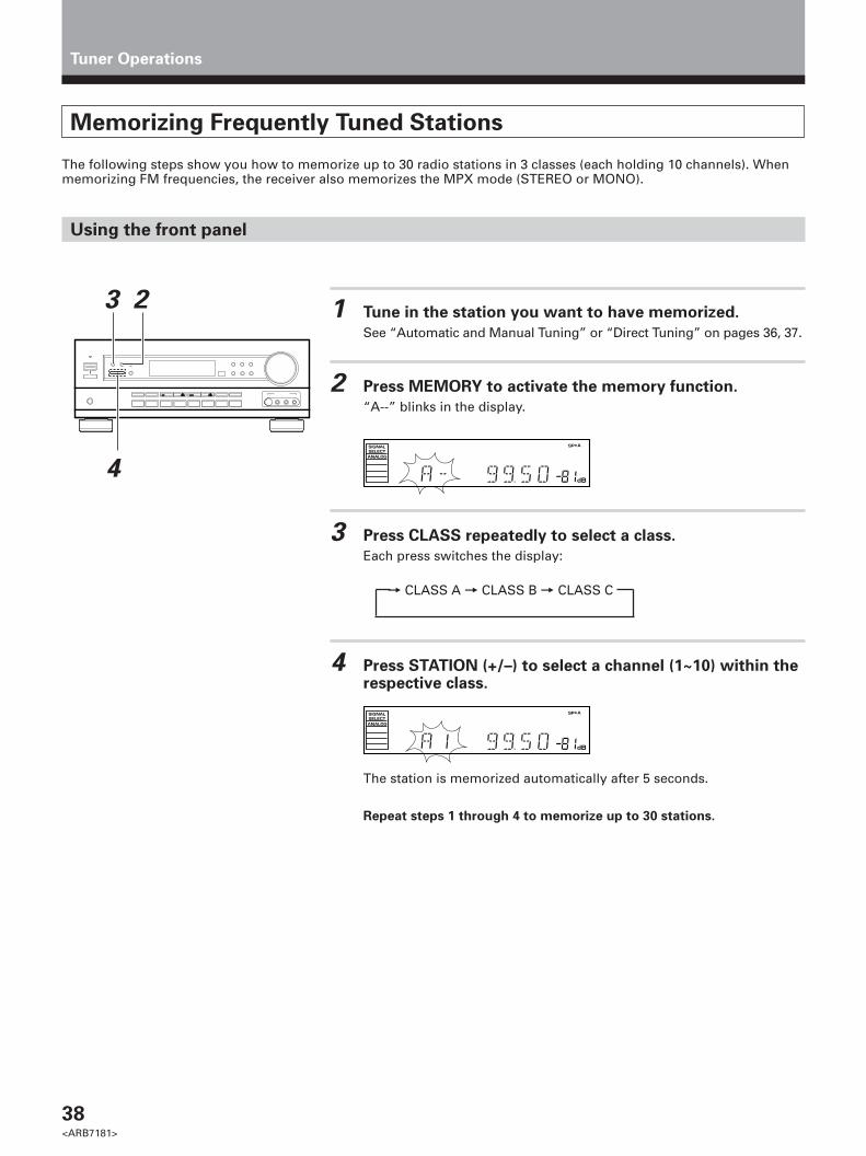
38<ARB7181>
Tuner Operations
Memorizing Frequently Tuned Stations
The following steps show you how to memorize up to 30 radio stations in 3 classes (each holding 10 channels). Whenmemorizing FM frequencies, the receiver also memorizes the MPX mode (STEREO or MONO).
Using the front panel
1 Tune in the station you want to have memorized.
See “Automatic and Manual Tuning” or “Direct Tuning” on pages 36, 37.
2 Press MEMORY to activate the memory function.
“A--” blinks in the display.
3 Press CLASS repeatedly to select a class.
Each press switches the display:
4 Press STATION (+/–) to select a channel (1~10) within therespective class.
The station is memorized automatically after 5 seconds.
Repeat steps 1 through 4 to memorize up to 30 stations.
= CLASS A = CLASS B = CLASS C
23
4dB
SPSIGNALSELECTANALOG
A
dB
SPSIGNALSELECTANALOG
A

39<ARB7181>
SE
T U
PO
PE
RA
TIO
N
Tuner Operations
Recalling the Memorized Stations
1 Press FUNCTION repeatedly on the remote or FM/AM onthe front panel to select the tuner. Press TUNER to setthe remote to the tuner operation mode.
The station you were previously tuned to is received automatically.
2 Press CLASS repeatedly to select a class.
Each press switches the display:
3 Use the number buttons to select the channel you want.
To select channel 7, press 7.To select channel 10, press `.For example : If 99.50 MHz (FM) was memorized in class B at channel 7.
To skip through each channel in orderPress CHANNEL +/– repeatedly.
Using the remote control
Using the front panel
1 Press FM/AM.
2 Press CLASS repeatedly to select a class.
3 Press STATION +/– to select the channel you want.
= CLASS A = CLASS B = CLASS C
2
13
dB
SPSIGNALSELECTANALOG
A
dB
SPSIGNALSELECTANALOG
A
DVD/LD
VCR 1
TV/SAT CD
TUNER
VCR 2 MD/TAPE
TV CONTROL
RECEIVER
DSP MODE
CH.SELECT ATT SIG.SELECT
MIDNIGHT
TEST TONE
AUDIO/VIDEO PRE-PROGRAMMED
REMOTE CONTROL UNIT
2 3
5
0
6
9 +10
TV/VCRCLASS
7 8
41
CHANNEL
MULTI CONTROL
ENTER
VOL VOL
FQ
FQ
+
–
TV FUNC
RECEIVER TV
MUTING
CN.LEVEL EFFECT
FL DIMMER FUNCTION DIRECT
MODE CHECKCOMMANDER
SET UP
Î
MEMU 2
1
3

40<ARB7181>
Playback
1 Turn on the power of the playback component.
2 Press RECEIVER to turn on the receiver.
Be sure that the standby indicator turns off onthe front panel.
3 Press FUNCTION to select the source you want to
playback.
The source you want to playback is displayed in the following order:
4 Press SIG. SELECT on the remote control or SIGNALSELECT on the front panel to select the input signalcorresponding to the source component.
(Refer to “Switching ANALOG/DIGITAL signal input” on page 29.)
5 Start playback of the component you selected in step 1.
6 Press VOL (+/–) to adjust the volume level in the range of--- dB (MIN) to 0 dB (MAX).
TUNER MD/TAPE 1 VCR 1
VCR 2TV/SAT DVD/LD
VIDEO
CD
2
6
3
DVD/LD
VCR 1
TV/SAT CD
TUNER
VCR 2 MD/TAPE
TV CONTROL
RECEIVER
DSP MODE
CH.SELECT ATT SIG.SELECT
MIDNIGHT
TEST TONE
AUDIO/VIDEO PRE-PROGRAMMED
REMOTE CONTROL UNIT
2 3
5
0
6
9 +10
TV/VCRCLASS
7 8
41
CHANNEL
MULTI CONTROL
ENTER
VOL VOL
FQ
FQ
+
–
TV FUNC
RECEIVER TV
MUTING
CN.LEVEL EFFECT
FL DIMMER FUNCTION DIRECT
MODE CHECKCOMMANDER
SET UP
Î
MEMU
2
3
6
STANDBYindicator
Other Operations
• Depending on the channel level setting, the MAX volume levelmay differ 0 to -10 dB from the level displayed.
• When this receiver is not going to be used for a long time, it isrecommended that you turn off the main power.
memo
4
4

41<ARB7181>
SE
T U
PO
PE
RA
TIO
N
Adjusting bass and treble (tone control)
Use BASS (+/–) or TREBLE (+/–) to adjust the low and high frequencies.
Press BASS (+/–) to adjust the low frequencies.
Press TREBLE (+/–) to adjust the high frequencies.
dB
SPSIGNALSELECTANALOG
A
dB
SPSIGNALSELECTANALOG
A
TREBLE +/–
BASS +/–
memo
• The tone control can be adjusted in a range of ±6.• Pressing + and – simultaneously restores the setting to 0.• In cases described below, the tone control cannot be adjusted.
1 Dolby/DTS mode is ON.2 DSP mode is ON.3 DVD 5.1ch input is selected.
Adjusting the brightness of the display
Use FL DIMMER to adjust the brightness of the fluorescent display.
Press FL DIMMER.
Four levels of brightness ranging from very dim to very bright can beselected. Each press changes the brightness of the display. When rotatingthrough the options, the default brightness can also be selected.
FL DIMMER
In standby, pressing STANDBY/ON while holding down the /DTS buttonreturns the display to the default brightness.
DVD/LD
VCR 1
TV/SAT CD
TUNER
VCR 2 MD/TAPE
TV CONTROL
RECEIVER
DSP MODE
CH.SELECT ATT SIG.SELECT
MIDNIGHT
TEST TONE
AUDIO/VIDEO PRE-PROGRAMMED
REMOTE CONTROL UNIT
2 3
5
0
6
9 +10
TV/VCRCLASS
7 8
41
CHANNEL
MULTI CONTROL
ENTER
VOL VOL
FQ
FQ
+
–
TV FUNC
RECEIVER TV
MUTING
CN.LEVEL EFFECT
FL DIMMER FUNCTION DIRECT
MODE CHECKCOMMANDER
SET UP
Î
MEMU
Other Operations
memo

42<ARB7181>
Recording from Audio Components
The following operations show you how to record audio to the cassette, DAT, or MD deck connected to the MD/TAPE 1or TAPE 2 MONITOR jacks.
1 Select the component you want to record.
Press SIG. SELECT on the remote or SIGNAL SELECT on the frontpanel to select “ANALOG” when making analog recordings, or“DIGITAL” when making digital recordings. (Refer to “SwitchingANALOG/DIGITAL signal input” on page 29.)
2 Prepare the program source.
(Tune in the radio station or load the CD, etc.)
3 Insert a blank tape into the cassette deck (MD/TAPE 1 orTAPE 2 MONITOR) and adjust the recording level (if necessary).
4 Start recording on the cassette deck, then start playbackfrom the source component.
Other Operations
1TAPE 2
MONITOR
SIGNAL SELECT
Record monitor (TAPE 2 MONITOR)
If you connect a cassette deck (etc.) with a record monitor function to theTAPE 2 MONITOR jacks, you can listen to the sound of the recording as it isbeing recorded.
Press TAPE 2 MONITOR to switch between the sound of therecording (TAPE 2 indicator on) and the sound of the sourcecomponent (TAPE 2 indicator off).
1
DVD/LD
VCR 1
TV/SAT CD
TUNER
VCR 2 MD/TAPE
TV CONTROL
RECEIVER
DSP MODE
CH.SELECT ATT SIG.SELECT
MIDNIGHT
TEST TONE
AUDIO/VIDEO PRE-PROGRAMMED
REMOTE CONTROL UNIT
2 3
5
0
6
9 +10
TV/VCRCLASS
7 8
41
CHANNEL
MULTI CONTROL
ENTER
VOL VOL
FQ
FQ
+
–
TV FUNC
RECEIVER TV
MUTING
CN.LEVEL EFFECT
FL DIMMER FUNCTION DIRECT
MODE CHECKCOMMANDER
SET UP
Î
MEMU
SIG. SELECT
The receiver’s volume, balance, tone (BASS, TREBLE, and LOUDNESS), and surround effects have no effecton the recorded signal.
memo
• This receiver outputs the input signal directly to the recordingdevice. As there is no conversion of the audio signal,recordings cannot be made from analog to digital, and similarlyfrom digital to analog.
• Recordings cannot be made from TAPE 2 MONITOR toMD/TAPE 1.
memo

43<ARB7181>
SE
T U
PO
PE
RA
TIO
N
Other Operations
Recording from Video Components
The following operations show you how to record audio and video to the video tape recorder connected to the VCR 1 orVCR 2 jacks.
1 Select the component you want to record.
Be sure to press SIG. SELECT on the remote or SIGNAL SELECT on thefront panel to choose “ANALOG”. (Refer to “Switching ANALOG/DIGITAL signal input” on page 29.)
2 Prepare the program source.
(Load the DVD or LD, etc.)
3 Insert a blank tape into the video tape recorder (VCR 1).
4 Start recording on the video tape recorder, then startplayback from the source component.
1
1
DVD/LD
VCR 1
TV/SAT CD
TUNER
VCR 2 MD/TAPE
TV CONTROL
RECEIVER
DSP MODE
CH.SELECT ATT SIG.SELECT
MIDNIGHT
TEST TONE
AUDIO/VIDEO PRE-PROGRAMMED
REMOTE CONTROL UNIT
2 3
5
0
6
9 +10
TV/VCRCLASS
7 8
41
CHANNEL
MULTI CONTROL
ENTER
VOL VOL
FQ
FQ
+
–
TV FUNC
RECEIVER TV
MUTING
CN.LEVEL EFFECT
FL DIMMER FUNCTION DIRECT
MODE CHECKCOMMANDER
SET UP
Î
MEMU
SIG. SELECT
SIGNAL SELECT
memo The receiver’s volume, balance, tone (BASS, TREBLE, and LOUDNESS), and surround effects have no effecton the recorded signal.
memo • Recording cannot be made from analog to digital, and similarlyfrom digital to analog.
• When recording a DVD, the recorded image may flicker or bedifficult to view because of the copy protection signalprogrammed on the DVD.
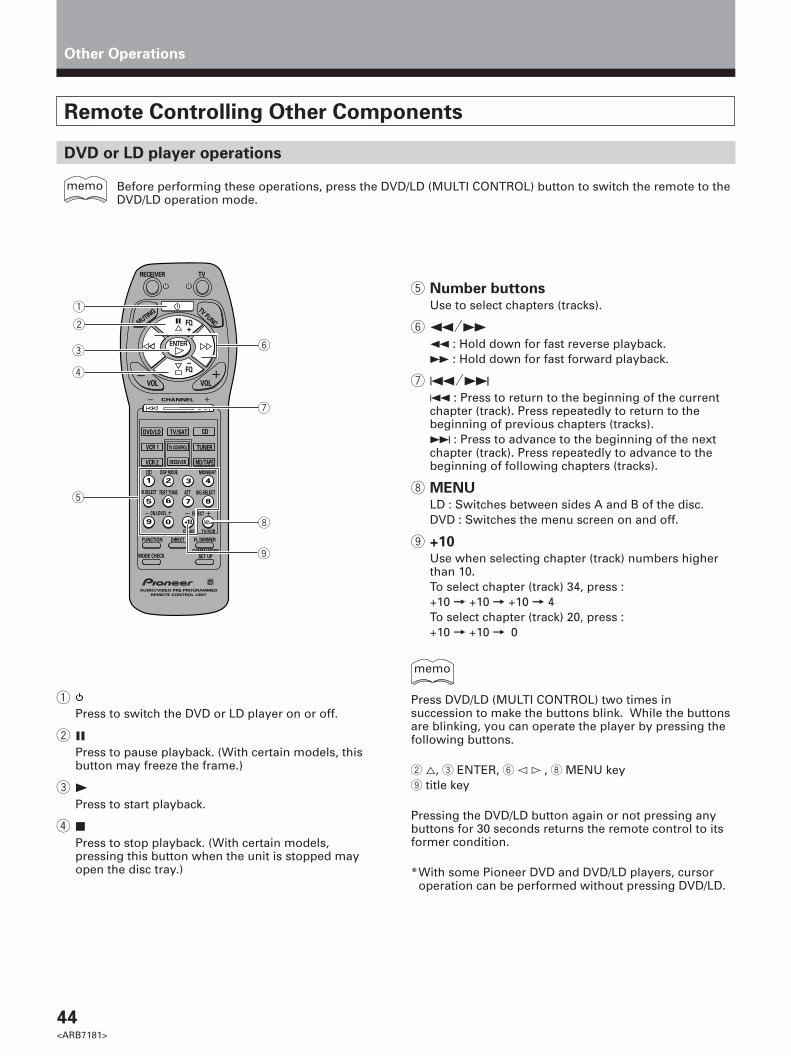
44<ARB7181>
Other Operations
Remote Controlling Other Components
DVD or LD player operations
Before performing these operations, press the DVD/LD (MULTI CONTROL) button to switch the remote to theDVD/LD operation mode.
5 Number buttonsUse to select chapters (tracks).
6 1˜¡1 : Hold down for fast reverse playback.¡ : Hold down for fast forward playback.
7 4˜¢4 : Press to return to the beginning of the currentchapter (track). Press repeatedly to return to thebeginning of previous chapters (tracks).¢ : Press to advance to the beginning of the nextchapter (track). Press repeatedly to advance to thebeginning of following chapters (tracks).
8 MENULD : Switches between sides A and B of the disc.DVD : Switches the menu screen on and off.
9 +10Use when selecting chapter (track) numbers higherthan 10.To select chapter (track) 34, press :+10 = +10 = +10 = 4To select chapter (track) 20, press :+10 = +10 = 0
DVD/LD
VCR 1
TV/SAT CD
TUNER
VCR 2 MD/TAPE
TV CONTROL
RECEIVER
DSP MODE
CH.SELECT ATT SIG.SELECT
MIDNIGHT
TEST TONE
AUDIO/VIDEO PRE-PROGRAMMED
REMOTE CONTROL UNIT
2 3
5
0
6
9 +10
TV/VCRCLASS
7 8
41
CHANNEL
MULTI CONTROL
ENTER
VOL VOL
FQ
FQ
+
–
TV FUNC
RECEIVER TV
MUTING
CN.LEVEL EFFECT
FL DIMMER FUNCTION DIRECT
MODE CHECKCOMMANDER
SET UP
Î
MEMU
1
2
3
4
5
6
7
9
8
memo
memo
Press DVD/LD (MULTI CONTROL) two times insuccession to make the buttons blink. While the buttonsare blinking, you can operate the player by pressing thefollowing buttons.
2 %, 3 ENTER, 6 @ # , 8 MENU key9 title key
Pressing the DVD/LD button again or not pressing anybuttons for 30 seconds returns the remote control to itsformer condition.
*With some Pioneer DVD and DVD/LD players, cursoroperation can be performed without pressing DVD/LD.
1Press to switch the DVD or LD player on or off.
2 8Press to pause playback. (With certain models, thisbutton may freeze the frame.)
3 3Press to start playback.
4 7Press to stop playback. (With certain models,pressing this button when the unit is stopped mayopen the disc tray.)

45<ARB7181>
SE
T U
PO
PE
RA
TIO
N
Other Operations
1Press to switch the TV on or off.
2 5Raises the volume of the TV.
3 ∞Lowers the volume of the TV.
4 Number buttonsUse to select a specific TV channel.
5 TVPress to switch the TV on or off. (This operation ispossible regardless of the current remote operationmode, however, it can only be used with thecomponent assigned to TV CONTROL.)
6 TV FUNCPress to switch the TV’s input (not possible with allmodels). (This operation is possible regardless of thecurrent remote operation mode.)
7 VOL (+/–)Use to adjust the volume of the TV.
8 CHANNEL (+/–)Use to select a TV channel.
TV operations
Before performing these operations, press TV CONTROL or TV/SAT (MULTI CONTROL) to switch the remoteto the TV operation mode.
memo
DVD/LD
VCR 1
TV/SAT CD
TUNER
VCR 2 MD/TAPE
TV CONTROL
RECEIVER
DSP MODE
CH.SELECT ATT SIG.SELECT
MIDNIGHT
TEST TONE
AUDIO/VIDEO PRE-PROGRAMMED
REMOTE CONTROL UNIT
2 3
5
0
6
9 +10
TV/VCRCLASS
7 8
41
CHANNEL
MULTI CONTROL
ENTER
VOL VOL
FQ
FQ
+
–
TV FUNC
RECEIVER TV
MUTING
CN.LEVEL EFFECT
FL DIMMER FUNCTION DIRECT
MODE CHECKCOMMANDER
SET UP
Î
MEMU
1
2
3
4
5
6
7
8

46<ARB7181>
Other Operations
1Press to switch the satellite tuner on or off.
2 5˜∞˜2˜3Use as cursor buttons to obtain information aboutprograms.
3 Number buttonsUse to select satellite channels.
4 ENTERPress to select the position selected using the cursorbuttons (5˜∞˜2˜3).
5 4˜¢ (GUIDE)Use to turn the program information screen on or off.
6 DISC (MENU)Use to turn the main menu on or off.
SAT (Satellite Tuner) operations
• The following operations are available from the receiver’s remote control after you recall a Satellite tunerpreset code (refer to “Setting up the Remote Control” on page 22).
• Before performing these operations, press the TV/SAT (MULTI CONTROL) button to switch the remote tothe TV/SAT operation mode.
memo
DVD/LD
VCR 1
TV/SAT CD
TUNER
VCR 2 MD/TAPE
TV CONTROL
RECEIVER
DSP MODE
CH.SELECT ATT SIG.SELECT
MIDNIGHT
TEST TONE
AUDIO/VIDEO PRE-PROGRAMMED
REMOTE CONTROL UNIT
2 3
5
0
6
9 +10
TV/VCRCLASS
7 8
41
CHANNEL
MULTI CONTROL
ENTER
VOL VOL
FQ
FQ
+
–
TV FUNC
RECEIVER TV
MUTING
CN.LEVEL EFFECT
FL DIMMER FUNCTION DIRECT
MODE CHECKCOMMANDER
SET UP
Î
MEMU
1
5
6
2
3

47<ARB7181>
SE
T U
PO
PE
RA
TIO
N
Other Operations
1Press to switch the CD player on or off.
2 8Press to pause playback.
3 3Press to start playback.
4 7Press to stop playback.
5 Number buttonsUse to select tracks.
6 1˜¡1 : Hold down for fast reverse playback.¡ : Hold down for fast forward playback.
7 4˜¢4 : Press to return to the beginning of the currenttrack. Press repeatedly to return to the beginning ofprevious tracks.¢ : Press to advance to the beginning of the nexttrack. Press repeatedly to advance to the beginning offollowing tracks.
8 MENUFor multi-disc CD changers, use to select the discnumbers (not possible with all models).For example, to select disc 34, press :3 = 4 = MENU.
9 +10Use when selecting track numbers higher than 10.For example, to select track 34, press :+10 = +10 = +10 = 4
CD player operations
Before performing these operations, press the CD (MULTI CONTROL) button to switch the remote to the CDoperation mode.
DVD/LD
VCR 1
TV/SAT CD
TUNER
VCR 2 MD/TAPE
TV CONTROL
RECEIVER
DSP MODE
CH.SELECT ATT SIG.SELECT
MIDNIGHT
TEST TONE
AUDIO/VIDEO PRE-PROGRAMMED
REMOTE CONTROL UNIT
2 3
5
0
6
9 +10
TV/VCRCLASS
7 8
41
CHANNEL
MULTI CONTROL
ENTER
VOL VOL
FQ
FQ
+
–
TV FUNC
RECEIVER TV
MUTING
CN.LEVEL EFFECT
FL DIMMER FUNCTION DIRECT
MODE CHECKCOMMANDER
SET UP
Î
MEMU
1
2
3
4
5
6
7
9
8
memo

48<ARB7181>
MD recorder operations
Before performing these operations, press the MD/TAPE (MULTI CONTROL) button to switch the remote tothe MD/TAPE operation mode.
memo
DVD/LD
VCR 1
TV/SAT CD
TUNER
VCR 2 MD/TAPE
TV CONTROL
RECEIVER
DSP MODE
CH.SELECT ATT SIG.SELECT
MIDNIGHT
TEST TONE
AUDIO/VIDEO PRE-PROGRAMMED
REMOTE CONTROL UNIT
2 3
5
0
6
9 +10
TV/VCRCLASS
7 8
41
CHANNEL
MULTI CONTROL
ENTER
VOL VOL
FQ
FQ
+
–
TV FUNC
RECEIVER TV
MUTING
CN.LEVEL EFFECT
FL DIMMER FUNCTION DIRECT
MODE CHECKCOMMANDER
SET UP
Î
MEMU
1
2
3
4
5
6
7
8
1Press to switch the MD recorder on or off.
2 8Press to pause playback.
3 3Press to start playback.
4 7Press to stop playback.
5 Number buttonsUse to select tracks.
6 1˜¡1 : Hold down for fast reverse playback.¡ : Hold down for fast forward playback.
7 4˜¢4 : Press to return to the beginning of the currenttrack. Press repeatedly to return to the beginning ofprevious tracks.¢ : Press to advance to the beginning of the nexttrack. Press repeatedly to advance to the beginning offollowing tracks.
8 +10Use when selecting track numbers higher than 10 or100.For example (in case of MJ-D707 (PIONEER)),1) To select track 15, press :+10 = 1 = 5
2) To select track 115, press :+10 = +10 = 1 = 1 = 5
To start recording
Press both 2 8 and 4 7 simultaneously.
Other Operations

49<ARB7181>
SE
T U
PO
PE
RA
TIO
N
1Press to switch the cassette deck on or off (notpossible with all models).
2 8Press to pause playback or recording.
3 3Press to start playback.
4 7Press to stop playback or recording.
5 1˜¡1 : Press to rewind the tape. Hold down duringplayback for fast reverse playback (not possible withall models).¡ : Press to fast forward the tape. Hold down duringplayback for fast forward playback (not possible withall models).
6 Number buttonsUse to operate deck 1 of a double cassette deck (notpossible with all cassette decks).
1 button (1)Press to rewind the tape. Hold down during playbackfor fast reverse playback (not possible with allmodels).
2 button (7)Press to stop playback or recording.
3 button (3)Press to start playback.
4 button (¡)Press to fast forward the tape. Hold down duringplayback for fast forward playback.
To start recording
Press both 2 8 and 4 7 simultaneously.You cannot record on deck 1 of a double cassette deck.
Cassette deck operations
Before performing these operations, press the MD/TAPE (MULTI CONTROL) button to switch the remote tothe MD/TAPE operation mode.
Other Operations
DVD/LD
VCR 1
TV/SAT CD
TUNER
VCR 2 MD/TAPE
TV CONTROL
RECEIVER
DSP MODE
CH.SELECT ATT SIG.SELECT
MIDNIGHT
TEST TONE
AUDIO/VIDEO PRE-PROGRAMMED
REMOTE CONTROL UNIT
2 3
5
0
6
9 +10
TV/VCRCLASS
7 8
41
CHANNEL
MULTI CONTROL
ENTER
VOL VOL
FQ
FQ
+
–
TV FUNC
RECEIVER TV
MUTING
CN.LEVEL EFFECT
FL DIMMER FUNCTION DIRECT
MODE CHECKCOMMANDER
SET UP
Î
MEMU
1
2
3
4
5
6
memo

50<ARB7181>
Other Operations
1Press to switch the VCR 1 or VCR 2 (VCR only on VSX-D508S) on or off (not possible with all models).
2 8Press to pause playback or recording.
3 3Press to start playback.
4 7Press to stop playback or recording.
5 Number buttonsUse to select a specific channel on the VCR's TVtuner.
6 1˜¡1 : Press to rewind the tape. Hold down duringplayback for fast reverse playback (not possible withall models).¡ : Press to fast forward the tape. Hold down duringplayback for fast forward playback (not possible withall models).
7 CHANNEL (+/–)Use to change the channel of the VCR’s TV tuner.
8 TV/VCRUse to switch the VCR’s antenna output between TVand VCR.
9 +10 (ENTER)Use to select the channel specified with the numberbuttons (not all models require this step).
To start recording
Press both 2 8 and 4 7 simultaneously.
VCR operations
Before performing these operations, press the VCR 1 or VCR 2 (MULTI CONTROL) button to switch theremote to the VCR operation mode.
DVD/LD
VCR 1
TV/SAT CD
TUNER
VCR 2 MD/TAPE
TV CONTROL
RECEIVER
DSP MODE
CH.SELECT ATT SIG.SELECT
MIDNIGHT
TEST TONE
AUDIO/VIDEO PRE-PROGRAMMED
REMOTE CONTROL UNIT
2 3
5
0
6
9 +10
TV/VCRCLASS
7 8
41
CHANNEL
MULTI CONTROL
ENTER
VOL VOL
FQ
FQ
+
–
TV FUNC
RECEIVER TV
MUTING
CN.LEVEL EFFECT
FL DIMMER FUNCTION DIRECT
MODE CHECKCOMMANDER
SET UP
Î
MEMU
1
2
3
4
5
6
7
9
8
memo

51<ARB7181>
SE
T U
PO
PE
RA
TIO
N
Background Control of Other Components
The following steps show you how to control one component while listening to another. This may be useful if you wantto rewind a tape while listening to CD, etc.
1 Select a component, then start playback.
For example:
Press FUNCTION to select the CD player, then press the CD button,andstart playing a CD. (You should hear the sound of the CD playing back.)
2 Press MODE CHECK to display the current operationmode.
The corresponding MULTI CONTROL button lights up.For example:
The CD button should light up to indicate that the remote is set tooperate the CD player.
3 Press MODE CHECK repeatedly to select anotheroperation mode.
Each time you press MODE CHECK, the next MULTI CONTROL buttonshould light, enabling you to operate the selected device.For example:
Press repeatedly to light the MD/TAPE button. The receiver’s functionremains set to CD (and you should still hear the CD player), but theremote control is now set to operate the tape deck.
4 Perform the desired operation(s).
The remote control remains in the selected operation mode, so youmay perform as many operations as necessary.For example :
Press 1 to rewind the tape.
5 Press MODE CHECK repeatedly to switch back to theoriginal operation mode.
You can also switch back to the original operation mode by pressingthe corresponding MULTI CONTROL button.For example :
Press MODE CHECK repeatedly to light the CD button, or press the CDbutton.
Other Operations
DVD/LD
VCR 1
TV/SAT CD
TUNER
VCR 2 MD/TAPE
TV CONTROL
RECEIVER
DSP MODE
CH.SELECT ATT SIG.SELECT
MIDNIGHT
TEST TONE
AUDIO/VIDEO PRE-PROGRAMMED
REMOTE CONTROL UNIT
2 3
5
0
6
9 +10
TV/VCRCLASS
7 8
41
CHANNEL
MULTI CONTROL
ENTER
VOL VOL
FQ
FQ
+
–
TV FUNC
RECEIVER TV
MUTING
CN.LEVEL EFFECT
FL DIMMER FUNCTION DIRECT
MODE CHECKCOMMANDER
SET UP
Î
MEMU
1
2,3,5
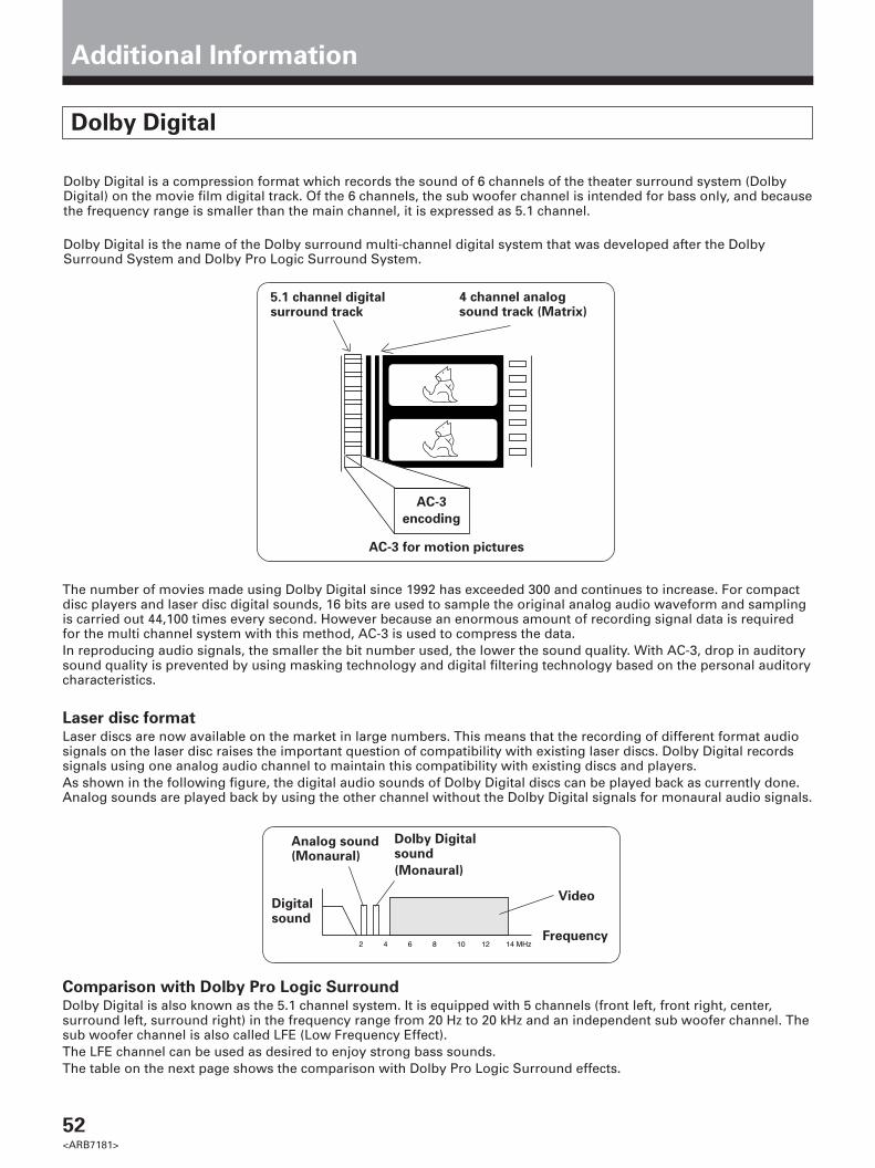
52<ARB7181>
Additional Information
Dolby Digital
Dolby Digital is a compression format which records the sound of 6 channels of the theater surround system (DolbyDigital) on the movie film digital track. Of the 6 channels, the sub woofer channel is intended for bass only, and becausethe frequency range is smaller than the main channel, it is expressed as 5.1 channel.
Dolby Digital is the name of the Dolby surround multi-channel digital system that was developed after the DolbySurround System and Dolby Pro Logic Surround System.
The number of movies made using Dolby Digital since 1992 has exceeded 300 and continues to increase. For compactdisc players and laser disc digital sounds, 16 bits are used to sample the original analog audio waveform and samplingis carried out 44,100 times every second. However because an enormous amount of recording signal data is requiredfor the multi channel system with this method, AC-3 is used to compress the data.In reproducing audio signals, the smaller the bit number used, the lower the sound quality. With AC-3, drop in auditorysound quality is prevented by using masking technology and digital filtering technology based on the personal auditorycharacteristics.
Laser disc formatLaser discs are now available on the market in large numbers. This means that the recording of different format audiosignals on the laser disc raises the important question of compatibility with existing laser discs. Dolby Digital recordssignals using one analog audio channel to maintain this compatibility with existing discs and players.As shown in the following figure, the digital audio sounds of Dolby Digital discs can be played back as currently done.Analog sounds are played back by using the other channel without the Dolby Digital signals for monaural audio signals.
5.1 channel digitalsurround track
4 channel analogsound track (Matrix)
AC-3
encoding
AC-3 for motion pictures
Digitalsound
2 4 6 8 10 12 14 MHzFrequency
Analog sound(Monaural)
Video
Dolby Digitalsound
(Monaural)
Comparison with Dolby Pro Logic SurroundDolby Digital is also known as the 5.1 channel system. It is equipped with 5 channels (front left, front right, center,surround left, surround right) in the frequency range from 20 Hz to 20 kHz and an independent sub woofer channel. Thesub woofer channel is also called LFE (Low Frequency Effect).The LFE channel can be used as desired to enjoy strong bass sounds.The table on the next page shows the comparison with Dolby Pro Logic Surround effects.
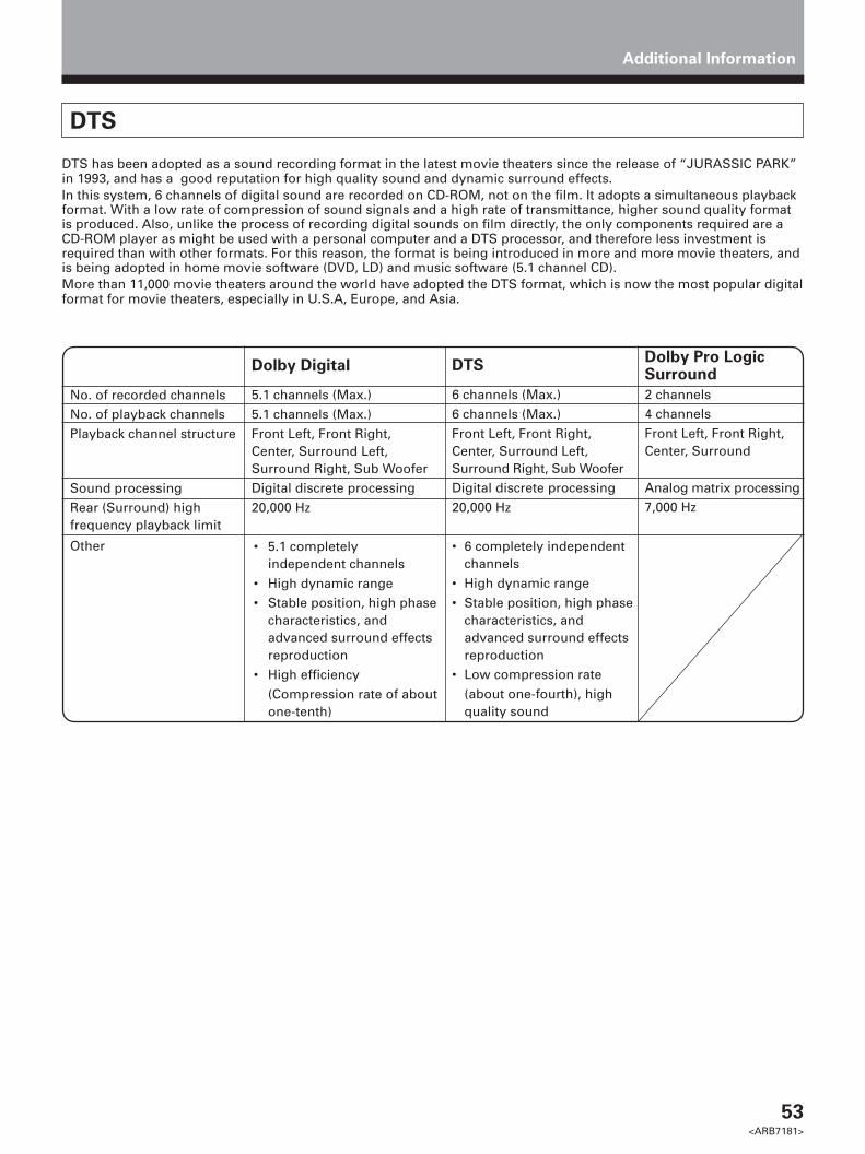
53<ARB7181>
DTS
DTS has been adopted as a sound recording format in the latest movie theaters since the release of “JURASSIC PARK”in 1993, and has a good reputation for high quality sound and dynamic surround effects.In this system, 6 channels of digital sound are recorded on CD-ROM, not on the film. It adopts a simultaneous playbackformat. With a low rate of compression of sound signals and a high rate of transmittance, higher sound quality formatis produced. Also, unlike the process of recording digital sounds on film directly, the only components required are aCD-ROM player as might be used with a personal computer and a DTS processor, and therefore less investment isrequired than with other formats. For this reason, the format is being introduced in more and more movie theaters, andis being adopted in home movie software (DVD, LD) and music software (5.1 channel CD).More than 11,000 movie theaters around the world have adopted the DTS format, which is now the most popular digitalformat for movie theaters, especially in U.S.A, Europe, and Asia.
Additional Information
No. of recorded channelsNo. of playback channelsPlayback channel structure
Sound processingRear (Surround) highfrequency playback limit
Other
Dolby Digital
5.1 channels (Max.)5.1 channels (Max.)Front Left, Front Right,Center, Surround Left,Surround Right, Sub WooferDigital discrete processing20,000 Hz
• 5.1 completelyindependent channels
• High dynamic range• Stable position, high phase
characteristics, andadvanced surround effectsreproduction
• High efficiency(Compression rate of aboutone-tenth)
Dolby Pro LogicSurround
2 channels4 channelsFront Left, Front Right,Center, Surround
Analog matrix processing7,000 Hz
DTS
6 channels (Max.)6 channels (Max.)Front Left, Front Right,Center, Surround Left,Surround Right, Sub WooferDigital discrete processing20,000 Hz
• 6 completely independentchannels
• High dynamic range• Stable position, high phase
characteristics, andadvanced surround effectsreproduction
• Low compression rate(about one-fourth), highquality sound

54<ARB7181>
Additional Information
Troubleshooting
Incorrect operations are often mistaken for trouble and malfunctions. If you think that there is something wrong withthis component, check the points below. Sometimes the trouble may lie in another component. Investigate the othercomponents and electrical appliances being used. If the trouble cannot be rectified even after exercising the checkslisted below, ask your nearest PIONEER authorized service center or your dealer to carry out repair work.
Cause
• The power plug is disconnected.
• The protection circuit may havebeen activated.
• Static electricity caused by dry air.
• Improper connections.
• Sound is muted.
• The volume is turned down.• The TAPE 2 MONITOR is ON.• Speakers are turned OFF.
• Improper connections.
• The input source is not properlyselected.
• Incorrect frequency.• The antenna is not connected.• AC-3 RF and/or digital cables are
near the antenna terminals andwires.
FM broadcasts
• The FM antenna is not fullyextended or is poorly positioned.
• Weak radio signals.
AM broadcasts
• The AM antenna is poorlypositioned.
• Weak radio signals.
• Interference cause by otherequipment (fluorescent lamp,motor, etc.).
Symptom
The power does not turn ON.
The unit does not respond when thebuttons are pressed.
No sound is output when a functionis selected.
No image is output when a functionis selected.
Considerable noise in radiobroadcasts.
Remedy
• Connect the power plug to the walloutlet.
• Disconnect the power plug fromthe outlet, and insert again.
• Disconnect the power plug fromthe outlet, and insert again.
• Make sure the component isconnected correctly (refer to pages9 to 14).
• Press MUTING on the remotecontrol.
• Adjust MASTER VOLUME.• Press the TAPE 2 MONITOR button.• Press SPEAKERS or SPEAKERS (A/B)
to select the speakers you connected.
• Make sure the component isconnected correctly (refer to pages10, 11).
• Press the correct function button.
• Tune in the correct frequency.• Connect the antenna (refer to page 8).• Route AC-3 RF and digital cables
away from the antenna terminalsand wires.
• Fully extend the FM wire antenna,position for best reception, andsecure to a wall.
• Connect an outdoor FM antenna(refer to page 8).
• Adjust the direction and positionfor best reception.
• Connect an additional internal orexternal AM antenna (refer to page 8).
• Turn off the equipment causing thenoise or move it away from thereceiver.
• Place the antenna farther awayfrom the equipment causing thenoise.

55<ARB7181>
Additional Information
Symptom
Broadcast stations cannot be selectedautomatically.
No sound from surround or centerspeakers.
Sound is produced from othercomponents, but not from LD or DVDplayer.
No sound is output or a noise isoutput when software with DTS isplayed back.
The sound is output intermittentlywhen software with DTS is playedback.
When a search is performed by aDTS compatible CD player duringplayback, noise is output.
Cannot be remote controlled.
The display is dark.
Cause
• Weak radio signals.
• Speaker settings are incorrect.
• The rear and/or center levels areturned down.
• The surround and/or centerspeakers are disconnected.
• SIGNAL SELECT is set incorrectly.
• The digital inputs are assignedincorrectly, or not at all.
• SIGNAL SELECT is set to“ANALOG”.
• A DVD player not compatible withDTS is used, or the setting of theDVD player is incorrect.
• The digital output level is adjustedon a CD player or other componentequipped with digital output leveladjustment capability. (The DTSsignal has been altered by theplayer, and cannot be read.)
• The overload indicator is lighting(refer to page 24).
• The search function performed bythe player slightly alters the digitalinformation, making it unreadable.
• The remote control batteries haveworn out.
• Too far away or bad angle ofoperation.
• There is an obstacle between thereceiver and the remote control.
• Strong light such as fluorescentlight is shining onto the unit'sremote control signal light-receiving window.
• A cord is connected to theCONTROL IN terminal on this unit.
• The FL DIMMER button is pushed.
Remedy
• Connect an outdoor antenna (referto page 8).
• Refer to “SPEAKER setting mode”on page 17 to check the speakersettings.
• Refer to “Setting the volume levelof each channel” on page 21 tocheck the speaker levels.
• Connect the speakers (refer topage 13).
• Set SIGNAL SELECT to ”DIGITAL” or”ANALOG” according to the type ofconnections made (refer to page 29).
• Set the digital input settingscorrectly (refer to page 16, 20, 21).
• Make digital connections (refer topage 11) and set SIGNAL SELECTto “DIGITAL” (refer to page 29).
• Refer to the instruction manualsupplied with the DVD player.
• Set the digital volume level of theplayer to full, or to the neutralposition.
• Set the ADVANCED THEATERmode to STANDARD (refer to page32).
• This is not a malfunction, but besure to turn the volume down toprevent the output of loud noisefrom your speakers.
• Replace the batteries (refer to page 6).
• Operate within 23 feet (7 m), 30° ofthe remote sensor on the frontpanel (refer to page 7).
• Remove the obstacle or operatefrom another position.
• Avoid exposing the remote sensoron the front panel to direct light.
• Connect cord to the correct jack.
• Press FL DIMMER on the remotecontrol repeatedly to return to thedefault.
If the unit does not operate normally due to external effects such as static electricityDisconnect the power plug from the outlet and insert again to return to normal operating conditions.

56<ARB7181>
Device
TAPE
CD
MD
TV
CATV*
Manufacturer
OPTIMUSPIONEERSONYTECHNICSKENWOODDENONRCAPHILIPSYAMAHAJVCTEACONKYOMARANTZSANYOOPTIMUSPIONEERSONYKENWOODSHARPTEACONKYODENONPIONEERRCAZENITHMAGNAVOXGE
PANASONICSONYTOSHIBAMITSUBISHIHITACHIJVCSHARPSANYOPHILIPSGOLDSTARRADIO
SHACKGRADIENTEPIONEERJERROLD
S.A.ZENITHPIONEER
Code
800800301,316,317,318304,326310,321,311309302,319,313312,322315,314,328303305,306,327,324,325320,308,307323,312,324313300300,329901903902904905906900,902601,610,615,616,617,618603,620607,610,603,612,629601,608,607,610,617,602,628618608,622,607604605,602,626,621609,610,602,621606,610,624,625,618613,623602,619,627621,614607610,623,621,602610,623,621,602
635600711,701,702,712,704,713,703714,716,715705,706,708,709707,717,710700
Manufacturer
TOSHIBASONYPANASONICJVCSAMSUNGSHARPAKAIRCAPIONEERSONYPANASONICKENWOODPHILIPSMITSUBISHIRCAPIONEER
RCASONYPIONEERRCA
ZENITHMAGNAVOXFISHERPANASONICTOSHIBAJVCHITACHISONYMITSUBISHI
SANYOSHARPGOLDSTAROPTIMUSGRANDIENTEPIONEERSONYTECHNICSKENWOODTEACDENONONKYOYAMAHAJVCFISHER
Code
001002003004005006007009000, 003101105,106103104100107100102 (DVD code)201,203202200401,406,408,414,405,413,411415403,404,417414,408,426,403410,426,412,427,425,420408,432,433405,409,426428,430,429,408,414,431,407408,401,406,436,434416,417,404,408409,420,421,422,423,424,408407410,412,425,435402,418,419411,409408,432,433,402,418,419452400,453801,806803804,807805810809,808811,812802813
Additional Information
Device
DVD
LD
SAT
VCR
TAPE
Preset Code List
* The CATV codes are preset into TV CONTROL.
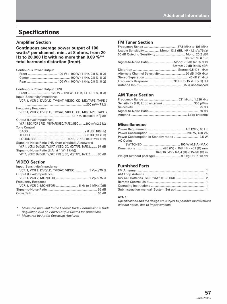
57<ARB7181>
Additional Information
Amplifier Section
Continuous average power output of 100watts* per channel, min., at 8 ohms, from 20Hz to 20,000 Hz with no more than 0.09 %**total harmonic distortion (front).
Continuous Power OutputFront .................................. 100 W + 100 W (1 kHz, 0.8 %, 8 Ω)Center ............................................... 100 W (1 kHz, 0.8 %, 8 Ω)Rear ................................... 100 W + 100 W (1 kHz, 0.8 %, 8 Ω)
Continuous Power Output (DIN)Front .......................... 120 W + 120 W (1 kHz, T.H.D. 1 %, 8 Ω)
Input (Sensitivity/Impedance)VCR 1, VCR 2, DVD/LD, TV/SAT, VIDEO, CD, MD/TAPE, TAPE 2
........................................................................200 mV/47 kΩFrequency Response
VCR 1, VCR 2, DVD/LD, TV/SAT, VIDEO, CD, MD/TAPE, TAPE 2.......................................................5 Hz to 100,000 Hz dB
Output (Level/Impedance)VCR 1 REC, VCR 2 REC, MD/TAPE REC, TAPE 2 REC ....... 200 mV/2.2 kΩ
Tone ControlBASS ................................................................. ± 6 dB (100 Hz)TREBLE .............................................................. ± 6 dB (10 kHz)LOUDNESS ................................. +9 dB/+7 dB (100 Hz/10 kHz)
Signal-to-Noise Ratio (IHF, short circuited, A network)VCR 1, VCR 2, DVD/LD, TV/SAT, VIDEO, CD, MD/TAPE, TAPE 2 .......... 97 dB
Signal-to-Noise Ratio [EIA, at 1 W (1 kHz)]VCR 1, VCR 2, DVD/LD, TV/SAT, VIDEO, CD, MD/TAPE, TAPE 2 .......... 80 dB
VIDEO SectionInput (Sensitivity/Impedance)
VCR 1, VCR 2, DVD/LD, TV/SAT, VIDEO ............... 1 Vp-p/75 ΩOutput (Level/Impedance)
VCR 1, VCR 2, MONITOR ...................................... 1 Vp-p/75 ΩFrequency Response
VCR 1, VCR 2, MONITOR .......................... 5 Hz to 7 MHz dBSignal-to-Noise Ratio .......................................................... 55 dBCross Talk ............................................................................. 55 dB
* Measured pursuant to the Federal Trade Commission’s TradeRegulation rule on Power Output Claims for Amplifiers.
** Measured by Audio Spectrum Analyzer.
SpecificationsSpecifications
+0–3
+0–3
FM Tuner SectionFrequency Range ...................................... 87.5 MHz to 108 MHzUsable Sensitivity ................. Mono: 13.2 dBf, IHF (1.3 µV/75 Ω)50 dB Quieting Sensitivity .................................. Mono: 20.2 dBf
Stereo: 38.6 dBfSignal-to-Noise Ratio ............................ Mono: 73 dB (at 85 dBf)
Stereo: 70 dB (at 85 dBf)Distortion .................................................... Stereo: 0.5 % (1 kHz)Alternate Channel Selectivity ............................. 60 dB (400 kHz)Stereo Separation ................................................... 40 dB (1 kHz)Frequency Response ............................. 30 Hz to 15 kHz (± 1) dBAntenna Input ................................................... 75 Ω unbalanced
AM Tuner SectionFrequency Range ........................................ 531 kHz to 1,620 kHzSensitivity (IHF, Loop antenna) .................................... 350 µV/mSelectivity ............................................................................ 25 dBSignal-to-Noise Ratio .......................................................... 50 dBAntenna ...................................................................Loop antenna
MiscellaneousPower Requirement ............................................ AC 120 V, 60 HzPower Consumption ............................................. 280 W, 400 VAPower Consumption in Standby mode ............................. 2.5 WAC Outlet
SWITCHED ............................................ 100 W (0.8 A) MAXDimensions ............................... 420 (W) × 158 (H) × 401 (D) mm
16-9/16 (W) × 6-1/4 (H) × 15-6/8 (D) inWeight (without package) ..............................9.8 kg (21 lb 10 oz)
Furnished PartsFM Antenna ................................................................................. 1AM Loop Antenna ....................................................................... 1Dry Cell Batteries (SIZE “AA” (IEC LR6)) ................................... 2Remote Control Unit ................................................................... 1Operating Instructions ................................................................ 1Sub instruction manual [System Set up] .................................. 1
NOTE:
Specifications and the design are subject to possible modificationswithout notice, due to improvements.

58<ARB7181>
WeWant You
LISTENINGFor A Lifetime
Selecting fine audio equipment such as the unit you’ve just purchasedis only the start of your musical enjoyment. Now it’s time to consider howyou can maximize the fun and excitement your equipment offers. Thismanufacturer and the Electronic Industries Association’s ConsumerElectronics Group want you to get the most out of your equipment byplaying it at a safe level. One that lets the sound come through loud andclear without annoying blaring or distortion-and, most importantly, withoutaffecting your sensitive hearing.
Sound can be deceiving. Over time your hearing “comfort level” adaptsto higher volumes of sound. So what sounds “normal” can actually be loudand harmful to your hearing. Guard against this by setting your equipmentat a safe level BEFORE your hearing adapts.
To establish a safe level:• Start your volume control at a low setting.• Slowly increase the sound until you can hear it comfortably and clearly,
and without distortion.
Once you have established a comfortable sound level:• Set the dial and leave it there.
Taking a minute to do this now will help to prevent hearing damage orloss in the future. After all, we want you listening for a lifetime.
We Want You Listening For A Lifetime
Used wisely, your new sound equipment will provide a lifetime of funand enjoyment. Since hearing damage from loud noise is often undetectableuntil it is too late, this manufacturer and the Electronic IndustriesAssociation’s Consumer Electronics Group recommend you avoidprolonged exposure to excessive noise. This list of sound levels is includedfor your protection.
DecibelLevel Example
30 Quiet library, soft whispers40 Living room, refrigerator, bedroom away from traffic50 Light traffic, normal conversation, quiet office60 Air conditioner at 20 feet, sewing machine70 Vacuum cleaner, hair dryer, noisy restaurant80 Average city traffic, garbage disposals, alarm clock
at two feet.
THE FOLLOWING NOISES CAN BE DANGEROUS UNDERCONSTANT EXPOSURE
90 Subway, motorcycle, truck traffic, lawn mower100 Garbage truck, chain saw, pneumatic drill120 Rock band concert in front of speakers, thunderclap140 Gunshot blast, jet plane180 Rocket launching pad
Information courtesy of the Deafness Research Foundation.
WeWant You
LISTENINGFor A Lifetime
For Assistance With Basic Set-up, Operation, or TroubleShooting, You May Contact Our Customer ServiceHotline at 1(800)421-1404(USA ONLY)
Power cord CAUTION!Handle the power cord by the plug. Do not pull out theplug by tugging the cord and never touch the power cordwhen your hands are wet as this could cause a shortcircuit or electric shock. Do not place the unit, a piece offurniture, etc., on the power cord, or pinch the cord.Never make a knot in the cord or tie it with other cords.The power cords should be routed such that they are notlikely to be stepped on. A damaged power cord cancause a fire or give you an electrical shock. Check thepower cord once in a while. When you find it damaged,ask your nearest PIONEER authorized service center oryour dealer for a replacement.
Maintenance of External Surfaces
• Use a polishing cloth or dry cloth to wipe off dustand dirt.
• When the surfaces are dirty, wipe with a soft clothdipped in some neutral cleanser diluted five or sixtimes with water, and wrung out well, and then wipeagain with a dry cloth. Do not use furniture wax orcleaners.
• Never use thinners, benzine, insecticide sprays orother chemicals on or near this unit, since these willcorrode the surfaces.
EST 1924
EIAEL
EC
TR
ONI C I ND
US
TR
IES
•A
SS O C I A T I O
N•
EST 1924
EIAEL
EC
TR
ONI C I ND
US
TR
IES
•A
SS O C I A T I O
N•

59<ARB7181>
Should this product require service in the U.S.A. and you wish to locate the nearest Pioneer
Authorized Independent Service Company, or if you wish to purchase replacement parts, operating
instructions, service manuals, or accessories, please call the number shown below.
8 0 0 – 4 2 1 – 1 4 0 4
Please do not ship your product to Pioneer without first calling the Customer Service Department at
the above listed number for assistance.
PIONEER ELECTRONICS SERVICE, INC.CUSTOMER SERVICE DEPARTMENTP.O. BOX 1760, LONG BEACH,CA 90801-1760, U.S.A.
For warranty information please see the Limited Warranty sheet included with your product.
Si ce produit doit être réparé au Canada, veuillez vous adresser à un distributeur autorisée Pioneerau Canada pour obtenir le nom de la Société de Service Autorisée Pioneer le plus près de chezvous. Ou encore, veuillez vous communiquer avec le Service de Clientèle de Pioneer:
Pioneer électroniques du Canada, Inc.Département de service au consommateurs300 Allstate Parkway, Markham, Ontario L3ROP2(905) 479-44111-877-283-5901
Should this product require service in Canada, please contact a Pioneer Canadian Authorized Dealerto locate the nearest Pioneer Authorized Service Company in Canada.Alternatively, please contact the Customer Service Department at the following address:
Pioneer Electronics of Canada, Inc.Customer Service Department300 Allstate Parkway, Markham, Ontario L3ROP2(905) 479-44111-877-283-5901
Pour obtenir des renseignements sur la garantie, veuillez vous reporter au feuillet sur la GarantieLimitée gui accompagne le produit.
For warranty information please see the Limited Warranty sheet included with your product.

60<ARB7181>
Published by Pioneer Electronic Corporation.Copyright © 1999 Pioneer Electronic Corporation.All rights reserved.
PIONEER ELECTRONIC CORPORATION 4-1, Meguro 1-Chome, Meguro-ku, Tokyo 153-8654, Japan
PIONEER ELECTRONICS [USA] INC. P.O. BOX 1540, Long Beach, California 90801-1540PIONEER ELECTRONICS OF CANADA, INC. 300 Allstate Parkway, Markham, Ontario L3R OP2, CanadaPIONEER ELECTRONIC [EUROPE] N.V. Haven 1087, Keetberglaan 1, 9120 Melsele, Belgium TEL: 03/570.05.11PIONEER ELECTRONICS AUSTRALIA PTY. LTD. 178-184 Boundary Road, Braeside, Victoria 3195, Australia, TEL: 03-9586-6300PIONEER ELECTRONICS DE MEXICO S.A. DE C.V. San Lorenzo Num 1009 3er piso Desp. 302 Col. Del Valle, Mexico D.F. C.P. 03100 TEL: 5-688-52-90
Printed in <ARB7181-A><99A00ZF0D00>


![MULTI CHANNEL AV RECEIVER STR-DH770 - Sony CHANNEL AV RECEIVER STR-DH770 Parts and Controls Receiver ... [18] Connecting 5.1-channel speaker system with front …](https://img.pdfslide.net/doc/110x75/5ab5b3567f8b9a6e1c8d1f5c/multi-channel-av-receiver-str-dh770-sony-channel-av-receiver-str-dh770-parts-and.jpg)