Embed Size (px)
Citation preview

GRAPHICAL MARIONETTE:
A MODERN-DAY PINOCCHIO
by
Delle Rae Maxwell
B.F.A., Rhode Island School of Design
1974
Submitted in partial fulfillmentof the requirements for
the degree of
MASTER OF SCIENCE IN VISUAL STUDIES
at the
MASSACHUSETTS INSTITUTE OF TECHNOLOGY
June 1983
Copyright (c) Massachusetts Institute of Technology 1983
Signature of authozr-. . . . .. . . . . . . . . . . . a. . . . . . . . . . . . . . . . . . . .
Department of Architecture
Friday, 13 May 1983
Certified by .......... . . . . . . . . . . . . . . . . . .Dr . Kenneth R . Sloan, Jr .
Assistant Professor of Computer GraphicsThesis Supervisor
Accepted by ........... ............................................Professor Nicholas Negroponte
Chairman, Departmental Committee for Graduate Students
RotcbMASSACHUSETTS INSTiTUTEOF TECHNOLOGY
AUG 5 1983
LIRPARIES

GRAPHICAL MARIONETTE:
A MODERN-DAY PINOCCHIO
by
Delle Rae Maxwell
submitted to the Department of Architecture on May 13, 1983in partial fulfillment of the requirements for the degree of
Master of Science in Visual Studies.
ABSTRACT
Representing the form and movement of human beings
naturally, expressively, and computationally is a challenging
endeavor. While the skeletal framework can be conveniently
described, conventional modelling techniques are generally
inadequate for rendering the flexible and irregular surface
features of the body. Detail that is sacrificed in articulating
the geometry of a life-like character can be compensated for by
realistically depicting the character's motion. It is theorized
that the most effective method of capturing the subtle dynamics
of human motion is to track that motion directly. With the goal
of complete body-tracking in view, a prototype system for
designing "graphical marionettes" animated by diverse inputs has
been developed.
The evolution of body modelling as both an artistic
and scientific concern are reviewed as precedents to current
modelling systems. The development of data structures,
animation programs, and some singular rendering techniques are
discussed within the context of the project. Several difficulties
in handling missing or occluded motion data are presented. Some
interesting animation scenarios are envisioned as future
applications of the system. Improvements to the present version
are suggested in the concluding chapter.
Thesis Supervisor: Dr. Kenneth R. Sloan, Jr.
Title: Assistant Professor of Computer Graphics
The work reported herein was supported by a grant from the Atari
Corporation.
2

TABLE OF CONTENTS
INTRODUCTION TO HUMAN MODELLING SYSTEMS ...................
CHAPTER ONE: HISTORY, BACKGROUND, AND CURRENT ISSUES ......
Replicants -...........................................................
The Measure of Man -...---.-...................................
Motion Study as a Scientific Discipline ..............
Human Motion Simulation . - -..............................
The Fundamental Tasks ... .............................
Related Research in Other Laboratories ...............
The Design of Natural Motion .........................
CHAPTER TWO: CONSTRUCTING THE GRAPHICAL
The Scope of the Project ..........
CHAPTER THREE: MODELLING THE BODY ......
A Further Measure of Man ..........
Establishing a Reference System ...
Motion Classification Terminology
From Body to Binary Tree: The Data
Components
MARIONETTE SYSTEM .
Structure .........
of the Body Data Base
Composing the Transformation Matrix ..................
Rendering Programs ...................................
CHAPTER FOUR: BODY-TRACKING ...............................
Background ...........................................
7
12
12
13
20
22
23
24
27
31
31
36
36
37
42
43
48
50
53
60
60
3
Developing the Body-Tracking Hardware ................
Interfacing Hardware and Software ....................
CHAPTER FIVE: EVOLUTION OF THE ANIMATION SYSTEM ...........
Keyframing ...........................................
A Walk Simulation ....................................
Underconstrained Systems .............................
CHAPTER SIX: SUMMATION .... s...................... .....
Extensions and Improvements ..........................
Future Animation Scenarios ...........................
APPENDIX A: A BRIEF USER'S MANUAL .........................
APPENDIX B: JOINT ROTATION LIMITS .........................
REFERENCES ............................. ..........
ACKNOWLEDGMENTS .................................. .... ...
4
64
67
69
69
71
81
84
84
85
88
99
104
109

TABLE OF FIGURES
Figure Page
1 From Metropolis, Human-to-Robot Feature Mapping ......... 8
2 Villard de Honnecourt, Notebook Page, c. 1235 ........... 14
3 Leonardo Da Vinci, Proportions of Head and Face ........ 15
4 Codex Huygens, Human Motion Study ..................... 17
5 Henry Dreyfuss Associates, "Humanscale" ............... 18
6 Labanotation Symbols .................................. 28
7 Combined Hardware and Software Diagram ................ 33
8 Skeleton and Stick Figure ............................. 37
9 Anatomical and Fundamental Positions .................. 39
10 Body Motion Reference Systems ......................... 40
11 General and Corresponding Binary Tree Structures ....... 45
12 Node Numbering Conventions for Body ................... 46
13 "Cloud Person" with One Random Variable ............... 55
14 "Cloud Person" Showing "Bones" ........................ 56
15 Bauhaus Theatre Performer ............................. 58
16 Keyframe Animation with Motion Traces.................. 72
17 Correspondence of Two Data Strutures .................. 76
18 Calculating Rotation Angles From Positional Data ....... 79
19 The Walk Simulation ................................... 80
5
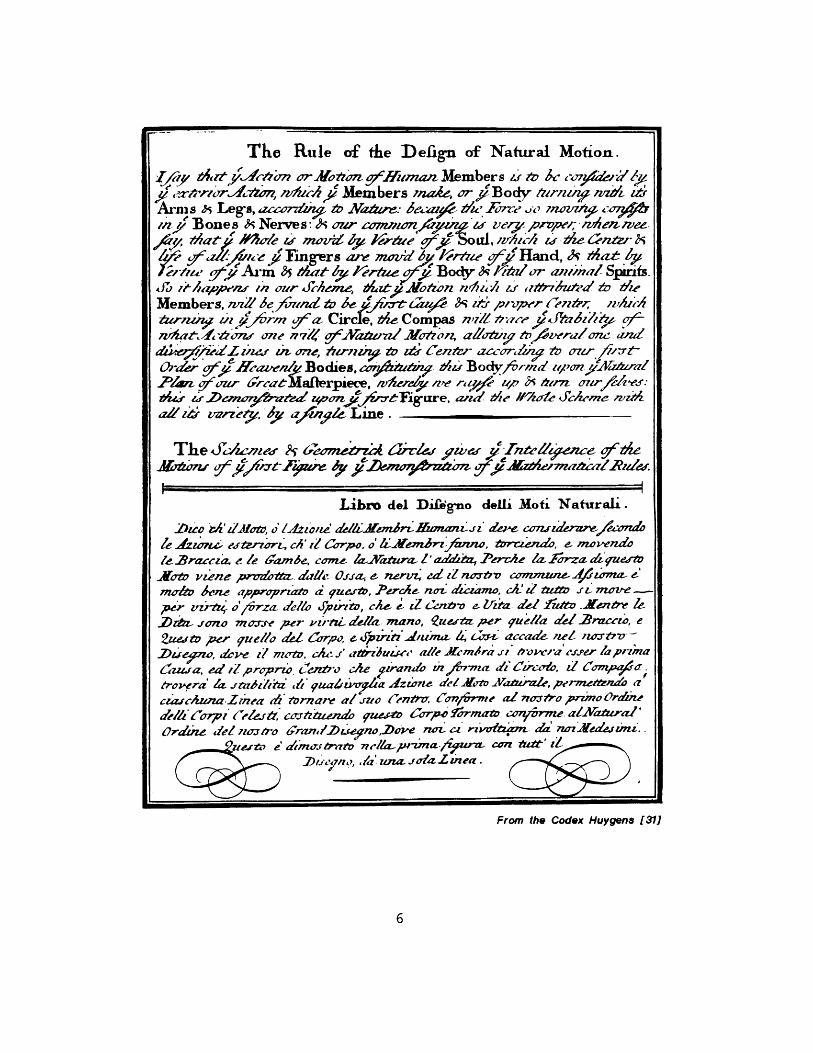
The Rule of die Defign of Natural Motion.
~j/~ ~z~A'1mOrmation g71 -zman Members i's- &~ kc~j4,
~~i ~ ~ ~~ Members ?na& e7%9 Bodylr/nnz4itArm s Ji Legs, azzonkiz & Na.*v: Aa;zA Z/'Fn L-7fo7/ 47$
i,n/ Bonesp -k Nerves:A ~Ozer a7,wIonA is ve-y pnvpt'/;,it'ee16,tht "r/e is moird Ivt Vere gV~S LI,,rti sZd d cn~l*
4 ~ , z- u Fng-ers are mcd,6 gro'9 ~adc~Mtl~I~iArt/m 35 th~at ly /'eriee40 Body A- K/vro awzrnal Spiits.
&ohn //u~p '?i ou- rheAe, 4 Mizyotwn zz-hit.i -h ~ -~u~di dieMembers, 7vzZI' &fiaund 'v& t16 u pl/vper Cn;/
twz~ azo /rm fa, Circle M>e Compas n,7LZ /ae ,1'knz'qt-t 10771d one 77q/e goCAMaian, Ae'oz, a&&IVz toev~era/one and-
a449!zedZ a &V4- one ?f'rflzi 47 £tf Center., azh ZDO7r,6,t-Order f Awnli Bodies, cO~drn Y,?4 fBody/- d zilon V-5/zr
Z/Am w ioza-6rat~laflerpiece, ,vhemre ne -,W, ze., O' &zn ~imlvv* &r lwwr ata zpvot,?# tgare, and the //'-4o/e c&-'me 'wzA
The &Iz.wev v 67eome&7z4 6Jrre yve- ;7ei7 ac ~'e
Libro del DiCftno delli M1ofi' Natirali.
k .Jzo'nw edtrzwr4 ,' Ca rpo. o/vn i de moveado1e- -Bracia. e le 6ramnA, come- ~~Yzue-1a~4 2ezetz ~z ~q
A'otv 'eene prvzonaz. azlle Orja, e- ne-ria ad zZ ?wcrz- comnmune 1.znma- e'm-t en.- apR~wcprzawv fi gu rto JercA4! noz- dzzmo, cki d &e zi- move-
per zrtu-i 1rza- deklA Xzrdo, Me- zZ Cnb&v e- lrlta delI- rUetz'.Xcvz&-!-b ion ao morzr' per- ,z p-irt del&- mano, i~eziz per rueiia "e 2rnzca, e
2Zuefz# per, 9 ue//o Yel C~zrpc, e4!zpzfi'd~zzza- 4 dzr- accade- net wr-
Cawta, ed 1Z propro. i:'ntrv che qziravdv M' /m-ma diz Czr-Cok d Cangpo~a;tr ,r Iz~z~~ i.zoedlt Vuzprefne'
cwc/zmaZ~ne ditorare altu eeo n" ConSrpwie zZ;7vozr/o pnimo OrdWzne
aWI/Crpi ji~ o~tzzwz f 9uZX & C-aTpC YraMZ& c47.rme. a/Natral'Ordzrie 1eZ,-zcjtYo 6'rarn/lae -oDow not -i rwvedtamn di izar.edejznu.
drnw-tr, n/t~~Ja~ma/igra-Contat, itlazi dzm.
From the Codex Huy gens [31)
6
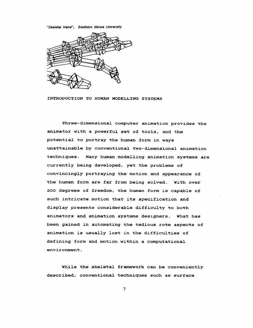
"Skeletal Hand", Southern Illinois University
INTRODUCTION TO HUMAN MODELLING SYSTEMS
Three-dimensional computer animation provides the
animator with a powerful set of tools, and the
potential to portray the human form in ways
unattainable by conventional two-dimensional animation
techniques. Many human modelling animation systems are
currently being developed, yet the problems of
convincingly portraying the'motion and appearance of
the human form are far from being solved. With over
200 degrees of freedom, the human form is capable of
such intricate motion that its specification and
display presents considerable difficulty to both
animators and animation systems designers. What has
been gained in automating the tedious rote aspects of
animation is usually lost in the difficulties of
defining form and motion within a computational
environment.
While the skeletal framework can be conveniently
described, conventional techniques such as surface
7
modelling and volumetric models are generally
inadequate for rendering the flexible and irregular
surface features of the body. In many cases the actual
physical mien of the graphic figure is relegated a
secondary status, due in part to the limits of
modelling techniques, and in part to greater concern
with motion representation. A primitive and
unconvincing appearance is the usual result.
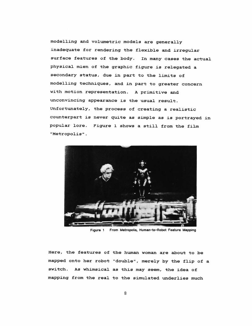
Unfortunately, the process of creating a realistic
counterpart is never quite as simple as is portrayed in
popular lore. Figure 1 shows a still from the film
"Metropolis".
Figure 1 From Metropolis, Human-to-Robot Feature Mapping
Here, the features of the human woman are about to be
mapped onto her robot "double", merely by the flip of a
switch. As whimsical as this may seem, the idea of
mapping from the real to the simulated underlies much
8

of the research in human modelling systems.
Numerous methodologies have been devised to record,
analyze, and describe the figure in motion. Notation
systems attempt to comprehensively define motion
primitives [5]. Although motion can be abstracted as a
series of rotations and translations of body segments,
it is the recombination of these primitives as smooth
natural motion that presents many obstacles. It is
theorized that the most natural and effective means of
accomplishing motion representation is to have a human
"scriptor" directly act out the motions that will
eventually be interpreted graphically. This method is
termed "scripting-by-enactment" [6]. The animated
output may be referred to as a "graphical marionette".
Scripting-by-enactment is accomplished by tracking the
actual motions of the human scriptor with position
sensing hardware [17].
Running parallel with the drive to incorporate
true- to-life human forms into computer graphics is the
drive to incorporate true-to-life, i.e. natural, human
actions into the use of computers and other machines.
Where we began by communicating non-interactively with
computers using an alpha-numeric format, we have
progressed to highly interactive styles and expanded
the I/O repertoire to include such means as
touch-sensitive displays and voice recognition/
synthesis. The next logical step to enhancing the
9
human-machine interface is to incorporate kinetic input,
or input by gesture. This technique furthers the
realization of the "fully responsive interface" [24],
facilitating conversation between the animator and the
computer, its various peripherals, and its graphic
inhabitants.
What is then needed in such a system are easily
defined body data structures, interchangeable drawing
modules which convincingly characterize the figure, and
quick feedback to the animator. The animator should be
able to script motion in the most direct way possible.
During system development, the animation progams must
be testable at each stage. This thesis explores these
issues of expressive appearance, user interface, and
natural motion within an animation application.
With the goal of integration with the completed
body-tracking hardware in view, a prototype system for
designing "graphical marionettes" animated by diverse
inputs has been developed. The body is abstracted as a
data structure and maintained as a template file.
Motion data contained in similar files can be mapped to
the corresponding body segments and processed in a
systematic fashion for each "frame" of animation. A
method for representing the body as "clouds" of points
is presented as a viable alternative to surface and
solid volume modelling. In addition to being
aesthetically engaging, its transparency obviates the
10
need to perform costly computation such as hidden
surface removal.
Chapter One provides a brief history of body and
motion modelling, and gives a synopsis of related
current research. Chapter Two presents an overview of
the Graphical Marionette project; both its long-range
and more immediate goals. Classification of the body
segments and motions, the creation of body templates,
methods for positioning the segments using rotational
primitives, and rendering programs are examined in
Chapter Three. Body-tracking techniques, a description
of the hardware configuration, and the
hardware-software interface are presented in Chapter
Four. Chapter Five chronicles the development of the
animation system in preparation for the actual tracking
data. Some of the problems with underconstrained
systems are mentioned. Chapter Six summarizes the
project and its concerns, and suggests some possible
future directions. Appendix A is intended as an
abbreviated user's manual to the current programs, and
Appendix B contains a table of joint rotation limits.
11
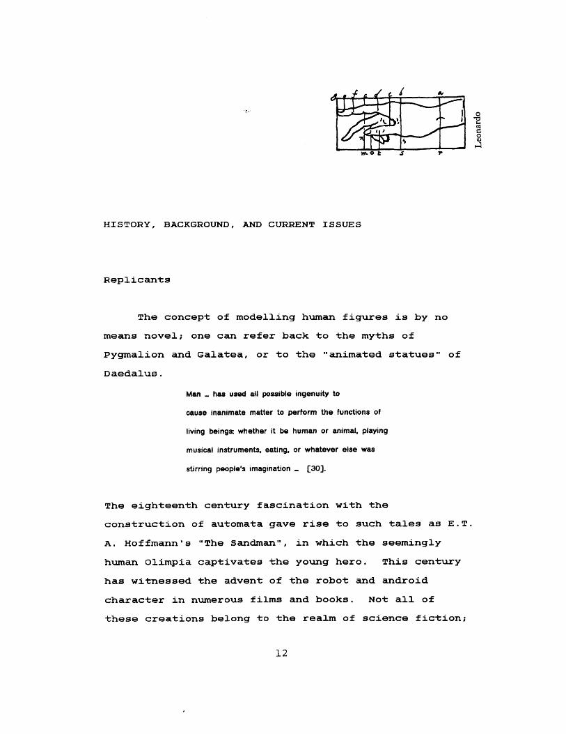
HISTORY, BACKGROUND, AND CURRENT ISSUES
Replicants
The concept of modelling human figures is by no
means novel; one can refer back to the myths of
Pygmalion and Galatea, or to the "animated statues" of
Daedalus.
Man . has used all possible ingenuity to
cause inanimate matter to perform the functions of
living beings: whether it be human or animal, playing
musical instruments, eating, or whatever else was
stirring people's imagination - [30].
The eighteenth century fascination with the
construction of automata gave rise to such tales as E.T.
A. Hoffmann's "The Sandman", in which the seemingly
human Olimpia captivates the young hero. This century
has witnessed the advent of the robot and android
character in numerous films and books. Not all of
these creations belong to the realm of science fiction;
12
robots, for example, have begun to be an integral part
of the manufacturing workforce. Accurate graphical
replication of the human figure in motion comprises an
important branch of research in computer science and
related disciplines.
The depiction of motion has an equally long
history.
The early Greeks were aware of the fact that
that the illusion of motion could be created by first
drawing a series of sequential pictures of motion
positions on a wall. By running or riding rapidly past
the pictures while gazing generally at them, the still
pictures appeared to spring to life, depicting the
motion originally conceived. [20]
Now, of course, the animation procedure is reversed;
one sits still and watches the images upon a screen
flashing by.
The Measure of Man
Our predominantly mathematical interpretation of
nature becomes evident when one considers the numerous
endeavors to create systems of proportion and order
devised to relate the human form to its environment.
The Pythagorean-Platonic tradition in the study of
geometry and proportion has wielded its influence in
13
psi'D 4
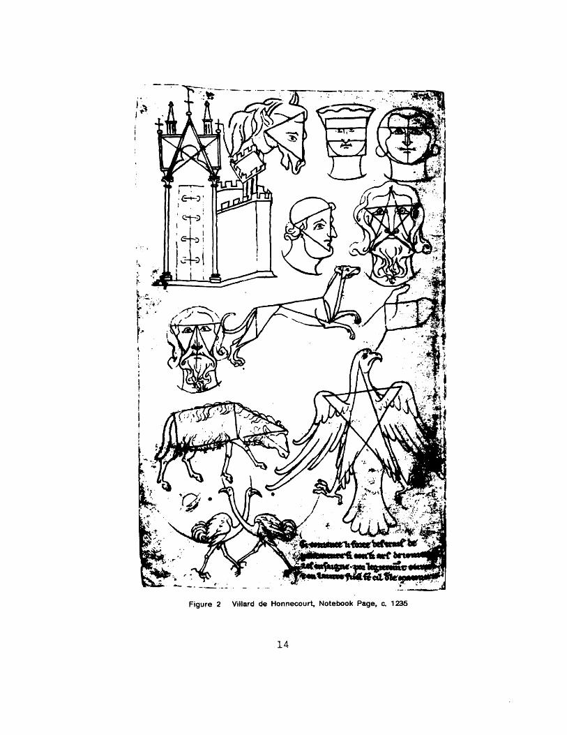
Figure 2 Villard de Honnecourt, Notebook Page, c. 1235
14
I '* ---m
the western world for over two thousand years, although
its use as a basis for human proportion reached its
zenith during the Middle Ages, Renaissance, and
Classical periods. Different uses of this tradition
were favored during different stylistic periods: the
medieval artist tends to project an established
geometrical norm into his imagery, as seen in Figure 2,
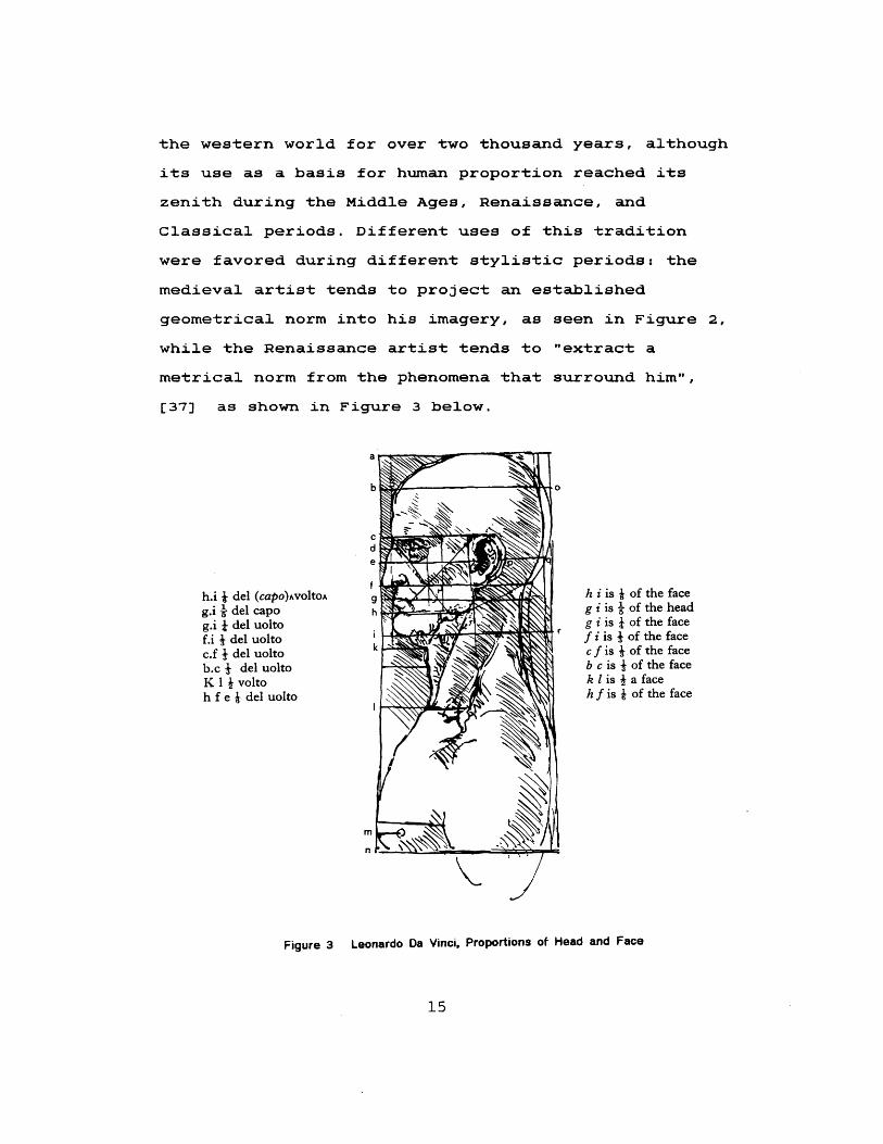
while the Renaissance artist tends to "extract a
metrical norm from the phenomena that surround him",
[37] as shown in Figure 3 below.
h.i * del (capo)AvoltoAg.i i del capog.i t del uoltof.i I del uoltoc.f 4 del uoltob.c I del uoltoK 1 I voltoh f e W del uolto
h i is * of the faceg i is l of the headg i is I of the face
r f i is J of the facecf is I of the faceb c is 4 of the facek 1 is 4 a faceh f is W of the face
mni
Figure 3 Leonardo Da Vinci, Proportions of Head and Face
15
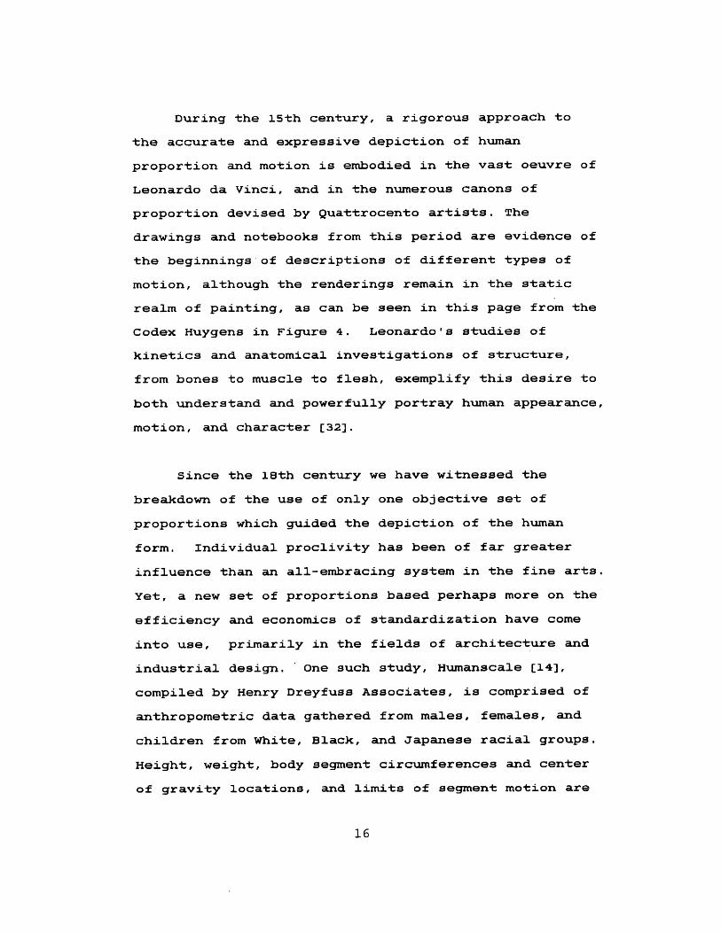
During the 15th century, a rigorous approach to
the accurate and expressive depiction of human
proportion and motion is embodied in the vast oeuvre of
Leonardo da Vinci, and in the numerous canons of
proportion devised by Quattrocento artists. The
drawings and notebooks from this period are evidence of
the beginnings of descriptions of different types of
motion, although the renderings remain in the static
realm of painting, as can be seen in this page from the
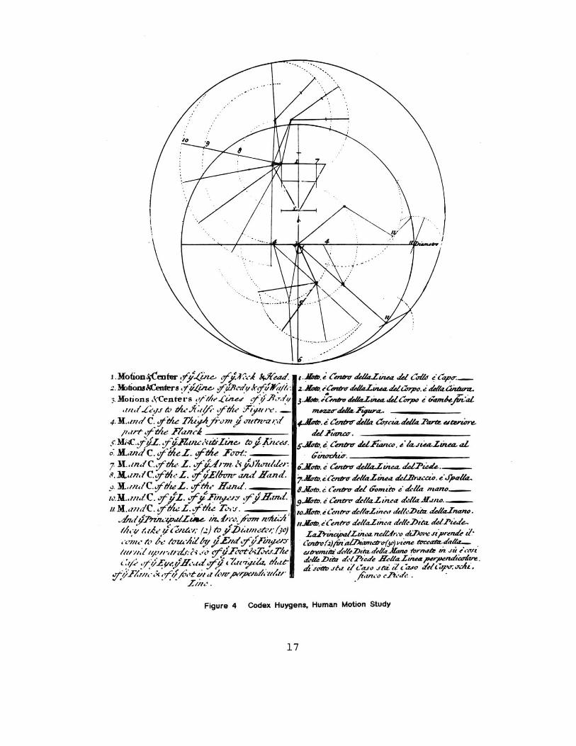
Codex Huygens in Figure 4. Leonardo's studies of
kinetics and anatomical investigations of structure,
from bones to muscle to flesh, exemplify this desire to
both understand and powerfully portray human appearance,
motion, and character [32].
Since the 18th century we have witnessed the
breakdown of the use of only one objective set of
proportions which guided the depiction of the human
form. Individual proclivity has been of far greater
influence than an all-embracing system in the fine arts.
Yet, a new set of proportions based perhaps more on the
efficiency and economics of standardization have come
into use, primarily in the fields of architecture and
industrial design. ' One such study, Humanscale [14),
compiled by Henry Dreyfuss Associates, is comprised of
anthropometric data gathered from males, females, and
children from White, Black, and Japanese racial groups.
Height, weight, body segment circumferences and center
of gravity locations, and limits of segment motion are
16
. NMotion 4Ceer uc464ze, 4Aead2. Nbons8Eenfras f4~~/
Notions W~(entet-s vL*11-e.Cztee IA4I
4.MRdhlelC. 9 ' die TA{X m/thLlcZJ
, rt qOy'd~e Jr/? _________
J Izrnd ca -aZ fse ~n
a . 'n1C.,fftzL. 5' e Hand._ __
1M.'ndC. ~ vFew~z v.iru~~M~audC. 4 /iLL$t/i 2 n
eCp/fe Z ff'Ad5iito iA Zl rztX7~~/
2. A"b e Cnvo A&L&uuAa W eu~ "a ao~n.5.,& e-aW;tPV&ZwaZeWpa e aa~n
4 gwro, e Zekpir& Aff dZaaWzz At& P ar ~rrrv
ddiuj ________
5 J~att i 42bv delAw 4 , zzeajw.uw
s4 it.i a'n, a4Z aeivea" lpZtiao. a.
9A.Ka e~ eA"~ del~ 6omdo el nfaan
wurav. i Centro,&e/A-Zincr Aele~.//r "MrPeWe
Za*6elz/wLzwa neUlw. dJPOM' "Rrende i/*
,A.ot2f,.t dauio frdc~a Welt&' 19mpT&cAd.I "~ o l ,ud.
Figure 4 Codex Huygens, Human Motion Study
17
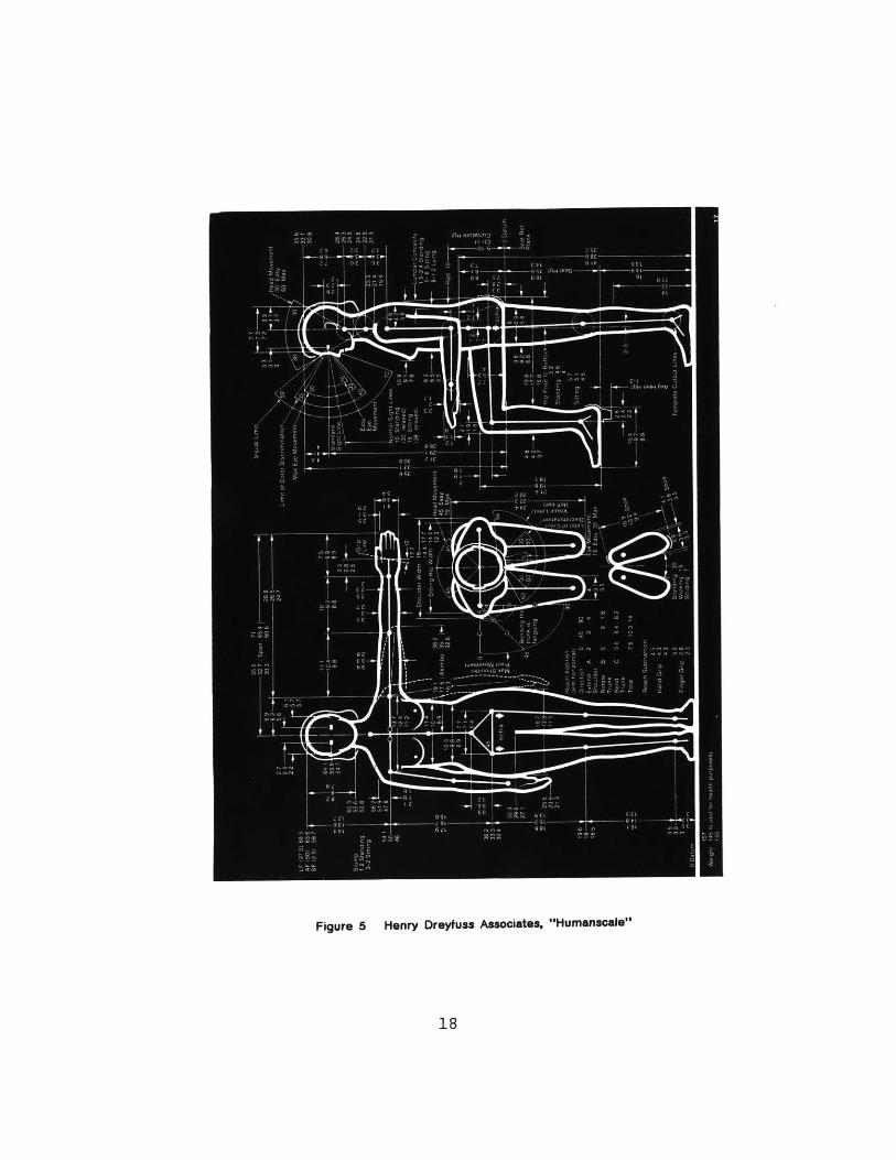
Figure 5 Henry Dreyfuss Associates, "Humanscale"
18
some of the factors considered. The measurements
gathered are summarized and analyzed, yielding a
statistical description for 95 percent of the people,
that is, those between the 2.5 and 97. 5 percentiles.
The "average" is the 50th percentile, which indicates
that the percentage of people at or below that certain
measurement is at 50. A page from Humanscale is shown
in Figure 5. This survey has provided the database for
Sammie, a human modelling system designed for "general
anthropometric analysis and design applications". [15]
The figure's proportions may be altered by varying the
percentiles, as well as change the somatotype of the
figure.
Yet even this seemingly extensive collection of
data on the human figure is not adequate to fully
describe the innumerable variations in proportion.
"There IS no standard size human!" is the observation
of Norman Badler [1], made in reference to the
employment of such a database in their own extensive
body modelling system at the University of Pennsylvania.
Perhaps a solution to the problem of seeking an
all-inclusive standardization is to consider the usage
in each instance. Research in human biomechanics
requires more precise measurement, even the measurement
of one particular person, as compared to the generation
of a human figure for animation, which may be
characterized by a certain degree of exaggeration.
19
Motion Study as a Scientific Discipline
Artistic interpretation of the meaning of motion
is only one aspect of the study of movement. An
observer in the medical field may be analysing movement
patterns to understand the difference between normal
and abnormal motion. An Olympic coach may wish to
closely observe the motion of an athlete, in order to
improve his or her performance. Designers of systems
such as Sammie need to observe the motions of a
simulated figure within a prospective work environment.
All of these applications require in varying degrees
involvement in disciplines such as kinesiology or
biomechanics.
Motion, the change of position of an object within
some frame of reference, is obviously a term
encompassing a lot of terrritory. In science, even
more than in art, systems of ordering and
classification are essential to the expansion of
knowledge in each particular field. In regards to
motion study, both the qualities and quantities must be
considered. Qualities of motion, exemplified by such
terms as contained, gentle, brusque, and the like are
useful in identifying motion. (These qualities are
also the most difficult to describe and reproduce
algorithmically !) The quantitative description, based
on measurement, is the concern of kinetics and
20

kinematics, both being a part of the science of
mechanics. With the kinematic approach, motion is
described without reference to mass or cause, referring
primarily to its measurement. Kinetics, or dynamics as
it is sometimes known, treats also the causes of motion,
which may be external or internal forces. The anatomy
of the body, its skeletal and musculature structure,
must also be studied in order to determine how motion
occurs.
A great deal of knowledge may be gained through
observation and measurement of the body in motion.
Photography and the subsequent motion picture allowed
for the viewing of the figure in motion, observable one
frame at a time. Stroboscopic images, made famous by
Edgerton and Killian show several instantaneous
postions on one negative of a stationary camera,
illuminated by a stroboscopic flash at some controlled
frequency. This produces an image which is sometimes
hard to analyze if certain parts of the body are
obscured by the path of the limbs. The technique of
electromyography (EMG) can be employed to measure the
extent of actual muscle contraction with surface or
needle electrodes placed near to the motor unit
controlling a certain muscle. The results may be
recorded on graph paper, or an oscilloscope. A tool
often used in gait analysis is the force plate. Placed
on the floor, it measures vertical and horizontal
forces exerted upon its plane. Electrogoniometers can
21
record joint angle changes in limb segments over time.
Such data can also be used to drive animated output, as
is mentioned later in the discussion of related human
modelling research. Other motion tracking devices will
be covered in greater detail in Chapter Four. As may
be imagined, such techniques produce extensive amounts
of data which would be difficult to classify and
analyze without the aid of a computer. With this aid,
not only can motion be analyzed in a controlled
environment, but motion and a graphical model can be
synthesized.
Human Motion Simulation
Recent developments in related computer fields
such as artificial intelligence, graphics, robotics,
and animation enable us to more closely approximate
human movement and gesture than ever before. Numerous
movement representation methods have been devised, both
"notation systems designed for recording movement, and
animation systems designed for the display of movement"
[2]. The aim of these systems ranges from entertainment,
characterized by a degree of artistic license in the
animation, to more detailed research applications;
simulations with the goal of modelling "exactly... a
process, theory or system" [28], drawing upon and
augmenting the knowledge of other related previously
mentioned discplines such as biomechanics and
22
kinesiology. Simulation systems generally can be
classified as kinematic or dynamic; the dynamic
simulation significantly increases the amount of
computation.
The Fundamental Tasks
Regardless of application, the fundamental
problems of representing human motion remain the same:
specifying the movements, and creating a graphical
image based on a physical model. The motion may be
directed by descriptive or analytic inputs, as
exemplified, respectively, by analog position sensors
or symbolic inputs (as in the Labanotation dance
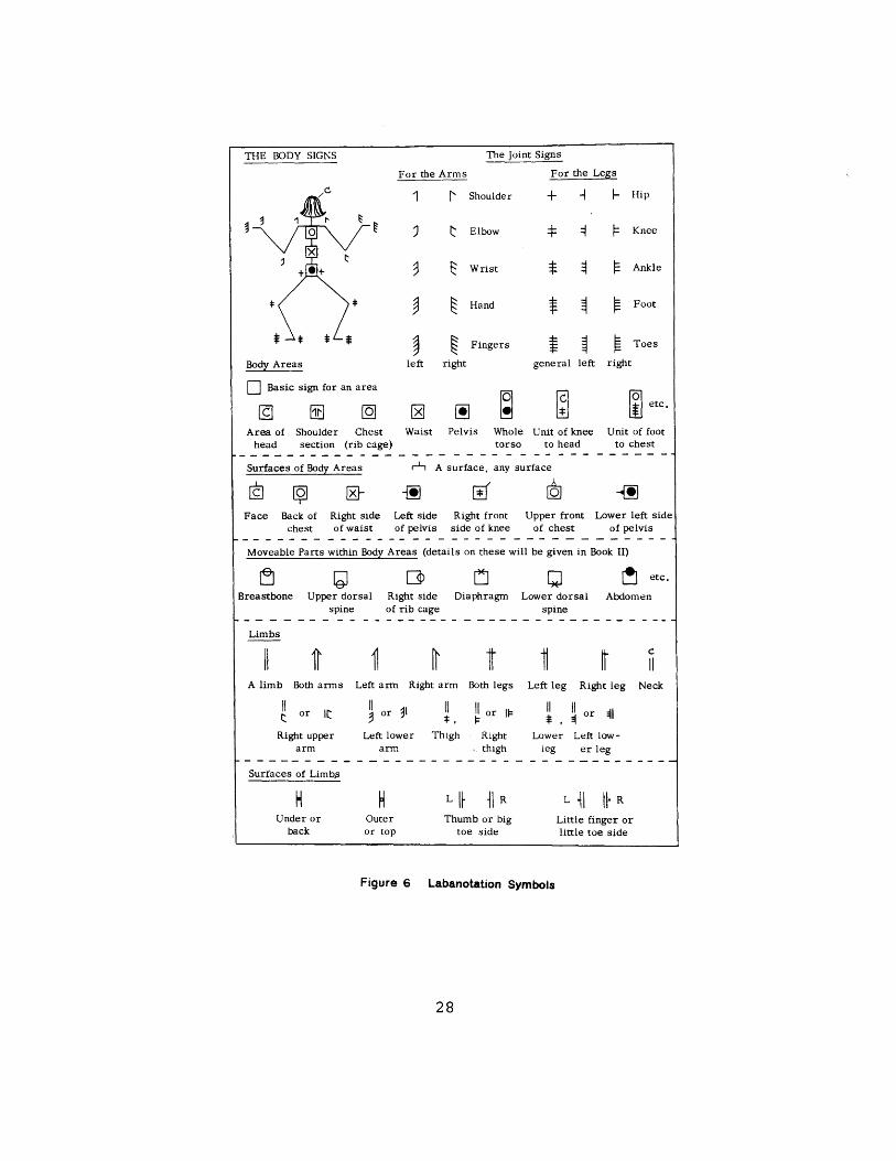
notation system [19] See also Figure 6). Processing
the input data, at the simplest level, requires
conversion to movement primitives which in turn are
used to animate the database model. These primitives
are primarily rotation, and to a lesser extent,
translation. The figure can be abstracted as a network
of linked segments driven by such motion.
The database, or description of the figure,
provides at least segment or joint names, connectivity
information, and segment lengths. Stick figures
provide a basis from which to work, but more realism is
achieved through wire frame or solid models. A more
natural-looking, but more complex figure may model
23
surface "skin" over the linear segments using a large
number of polygons, or surface patches. Such surface
modelling techniques are not entirely satisfactory, as
problems such as deformations of the surfaces near
moving joints occur. [5] Computational cost is high in
trying to rectify these problems. Other approaches,
such as volume models (cylinders, ellipsoids, or
spheres) are also being explored as alternatives to
these methods. This may seem familiar: perhaps it is
appropriate at this point to refer to the 13th century
illustration seen previously in Figure 2. At the other
end of the scale of "realism" are NYIT's whirling
geometric solids suggestive of a dancing figure,
exemplifying the creative use of such animation systems.
Nevertheless, a common goal, realistic portrayal
of human form and motion, constitutes a focal point for
diverse research. Brief descriptions of current
systems under development are presented as examples of
some of the techniques mentioned above.
Related Research at Other Laboratories
The University of Pennsylvania group, directed by
Badler, [1,2,3,4,5) is conducting human movement
research based primarily in these areas: computer
graphics used for motion synthesis, computer vision,
Labanotation [19] for movement notation, language
24
analysis, and robotics [2]. One of the applications of
this system is the simulation of the "activities of
several people in a workstation environment" [2).
Directions, facings, revolutions, contacts, and shapes,
concepts culled from the Labanotation system, are used
as positional and directional movement primitives. In
order to represent the dynamic qualities of movement,
i.e., how one moves (slow, quick, forceful), other
notation systems are being investigated which can be
incorporated with the concepts of Labanotation.
Describing these dynamic qualities using natural
language would require using motion verbs and their
modifiers developed within a special purpose task
specification language. This method extends this
research into ancillary fields such as language
analysis, thereby increasing the scope and complexity
of the research. The graphical representation is
modelled using spheres, which are mapped onto the
display as circles and ellipses, making for a somewhat
lumpy looking, albeit versatile character known as the
Bubble Person. The emphasis in this system is more on
the representation and synthesis of movement, and the
development of task specification languages, than on
the physiognomy of the figure.
At Ohio State University, Zeltzer and the Computer
Graphics Research Group are modelling human and animal
forms as skeletons, simulating the bone and joint
structures before tackling the problem of muscle and
25
flesh [38,39,40,41]. Articulated, realistically
modelled skeletal figures combined with motor control
programs have been used to create convincing walking
sequences over flat terrain. This system is not based
on a movement description notation such as the
Labanotation [19] used by Badler, et al [1,2,3,4,5], as
they doubt its extendability to other (non-human or
imaginary) figures. Their method is likened to the
GRAMPS [27] system, with its "facilities for defining
articulated objects" [41]. Joint movement primitives,
"bends", are called in two ways. The first is by
keyboard commands, entering rotation amounts for each
joint. Alternatively, an animator may choose to
describe "tasks" to a task manager, which calls motor
control programs, which then in turn activate local
motor programs. These local motor programs, or LMPs,
act upon the skeleton database by changing joint
rotation values, and thus represent bend primitives.
Work is being done to control the LMPs during cycles of
motion by the implementation of finite-state machines.
(The abstraction of the body and its motion as a set of
machines is a concept that Leonardo da Vinci discussed
in his own work!) An eventual goal here, as well as at
the University of Pennsylvania, is further development
of systems which accept natural language scripting as
input [41].
Yet another approach to human animation, under
development by Calvert, Chapman, and Patla at Simon
26
Fraser University applies both symbolic
(Labanotation-based) and analog (electrogonimeter)
inputs to motion control [10,11]. In this case, the
graphics display can be driven by both simultaneously.
The notation pattern can be built to produce an
animation duplicating that obtained from the analog
data. Modifications can be made after observing the
actual movement to check for subtleties which may have
been overlooked by the electrogoniometer's input.
Three potential applications are being investigated.
The system can first function as a tool assisting in
dance notation and its visualization. Second are its
clinical usages, primarily in studying motion
abnormalities. Lastly, the macrolanguage developed for
the human animations is also is used in robot
manipulator control [11]. Previous difficulties in the
synchronization of the two inputs [10] appear to have
been resolved in later versions [11]. Its
implementation as a kinematic simulation limits the
types of motion that can be performed, but this is
viewed as a reasonable compromise in terms of
practicality.
The Design of Natural Motion
Choreography of motion, whether in determining
primitive moves, planning a walk cycle, or
synchronizing multiple figures, has a predecessor in
27
THE BODY SIGNS The Joint Signs
For the Arms For the Legs
Shoulder -+-] |-
Elbow
Wrist
Hand
* ( (Ankle
Foot
Fingers Toes
left right general left right
ir reetc.
rea of Shoulder Chest Waist Pelvis Whole Unit of knee Unit of footiead section (rib cage) torso to head to chest
Surfaces of Body Areas r A surface, any surface
Face Back of Right side Left side Right front Upper front Lower left sidechest of waist of pelvis side of knee of chest of pelvis
Moveable Parts within Body Areas (details on these will be given in Book II)
Breastbone Upper dorsalspine
Fetc.
Right side Diaphragm Lower dorsal Abdomenof rib cage spine
Limbs
A limb Both arms Left arm Right arm Both legs Left leg Right leg Neck
or or 9 or ||or or
Right upper Left lower Thigh Right Lower Left low-arm arm thigh leg er leg
Surfaces of Limbs
HUnder or
back
HOuteror top
L 1I 11R
Thumb or bigtoe side
L 1 1. R
Little finger orlittle toe side
Figure 6 Labanotation Symbols
28
Hip
Knee
Body Areas
Bai si nfor n area
A
the field of dance. Some of the motion modelling
systems in use today have adapted Labanotation, a
system devised in 1928 by Rudolf Laban to record and
analyse motion in dance. With its comprehensive
categorization of direction, system of reference,
rotations, timimg, and so on, it has been relatively
straightforward to represent computationally. A page
from the glossary of symbols is shown in Figure 5. The
specification of HOW a motion is to be performed is not
something that this system accounts for, and must be
augmented by some other method. Ironically, dancers
themselves tend not to employ this system, because of
the large numbers of symbols which must be memorized.
A goal of many simulation systems is the use of
natural language for simple top-level dynamic motion
specification. With a flourish of the hand, commanding
"waltz over there across the floor!" is certainly more
natural and straightforward than relating trajectory
descriptions composed of joint angles, velocities and
accelerations to joint torques, which eventually are
used to graphically realize that trajectory. However,
this kind of simplicity at the animator's level
presupposes a complex "hidden" system drawing upon
knowlege gained from artificial intelligence and
robotics research as well as from language analysis.
Without prior knowledge about about dance, rhythm,
grace and implied direction, how easily can the concept
of "waltz" and even "across" be described? Is there a
29
point at which the verbal description fails to
communicate the desired action?
The manipulation of a graphic entity appearing to
move autonomously and smoothly, capturing the
subtleties of human gesture, remains a significant
issue and challenge. In response to this challenge, we
maintain that the most direct way to move a graphic
figure is by "showing" it how, as a choreographer might
instruct a dancer.
30
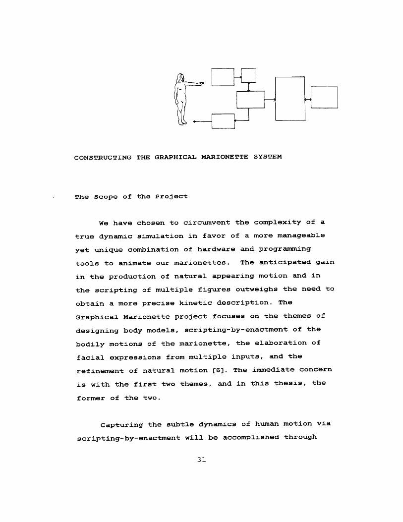
CONSTRUCTING THE GRAPHICAL MARIONETTE SYSTEM
The Scope of the Project
We have chosen to circumvent the complexity of a
true dynamic simulation in favor of a more manageable
yet unique combination of hardware and programming
tools to animate our marionettes. The anticipated gain
in the production of natural appearing motion and in
the scripting of multiple figures outweighs the need to
obtain a more precise kinetic description. The
Graphical Marionette project focuses on the themes of
designing body models, scripting-by-enactment of the
bodily motions of the marionette, the elaboration of
facial expressions from multiple inputs, and the
refinement of natural motion [6]. The immediate concern
is with the first two themes, and in this thesis, the
former of the two.
Capturing the subtle dynamics of human motion via
scripting-by-enactment will be accomplished through
31
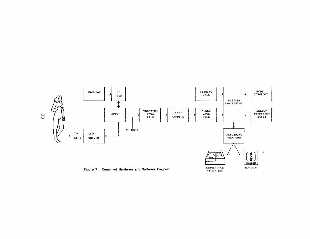
body tracking. The hardware being developed for this
project will parameterize human motion in real time and
make this data available to the other system components
in the host computer. To produce such a system,
concurrent work on building tracking hardware [17] and
this modelling software must occur. More importantly,
the two must interface properly. Figure 6 shows the
overall system architecture.
Two cameras will be used to sense the positions of
an array of LEDs attached to a garment worn by the
scriptor. These signals are sent to the Op-Eye as
"frames", a set of 15 or more discrete points, where
they are amplified and digitized, then output to the
AppleII. The Applell also serves as the master
controller of the tracking hardware. After further
low-level processing, the data is shipped to the host
via an RS-232 serial interface, and stored as a data
file.
Mapping of the positional data from the coordinate
space of the tracking device to the body data structure
must be done before passing the data to the animation
programs. conversion to rotational information must
also occur. A display processing module (the animation
programs) accepts input data used to update current
locations of the figure. For each frame, this module is
passed rotational data for each segment, as well as
viewing data, the body database, and commands for
32
DISPLAYPROCESSING
TRACKING DAAANGLE S]
LiAPL FILE MAPPIG FIL E
TO HOSTTO LED RENDERINGLFDs DRIVER PROGRAMS
Figure 7 Combined Hardware and Software Diagram IE-ONCE MONITOR
specifying rendering style and control of peripheral
devices such as the write-once videodisc, for immediate
playback. Appropriate rendering programs utilize the
final screen coordinate output to produce each frame of
animation on a color raster display.
The "scripting space" is defined by the fields of
view of the cameras and will be located in the MIT
Architecture Machine Group's "Media Room". This room
is about sixteen feet long, eleven feet wide and eight
feet high. The far wall is a back-projection screen
illuminated by a projector situated in an adjoining
room. For visual feedback, the scriptor may make use
of any combination of a CRT terminal, a graphics
monitor, the projection screen, a "head-mounted
display" [9], and a 3-D display [26]. The latter two
devices were created at the Architecture Machine Group.
Discussed in Chapter Three are the processes of
abstracting the body's structure and motion so that it
may be represented computationally. The "body
template" data structure, the composition of rotation
and translation matrices, and the rendering programs
are also described. Chapter Four is an overview of
body-tracking and the proposed system hardware. The
animation, to be driven ultimately by the tracking data,
has been implemented in several preliminary stages,
which are described in Chapter Five. The initial
method, joint angle input, can be done independently of
34
the body tracking, and provides a means of testing for
errors. Animation sequences can be created by
"keyframing", a traditional two-dimensional animation
method adapted to three dimensions. The next stage is
the use of simulated walk sequence data. This data is
created on the AppleII, transferred to the the host,
and mapped to the body model as the tracked data will
be mapped. Thus, it is useful in development and
preliminary debugging of the various system components.
During the early development of body tracking the
number of limbs that can be tracked will be limited.
The problem of determining limb position from partial
data arises. A typical example would be finding the
elbow position given that for the wrist and the
shoulder. Occlusion of one body part by another
creates the same difficulty. By checking anatomical
constraints and checking past history of a motion
sequence, interpolation of positions within a legal
range can be done. The concluding section of Chapter
Six discusses some interesting animation scenarios made
possible by scripting-by-enactment.
35
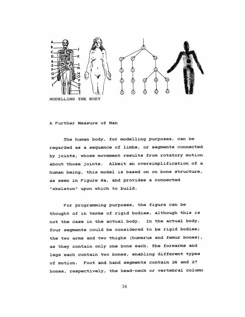
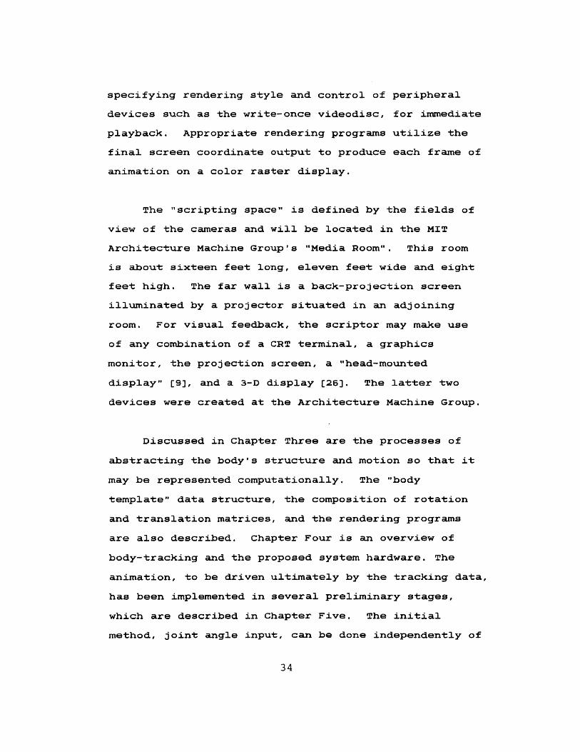
MODELLING THE BODY
A Further Measure of Man
The human body, for modelling purposes, can be
regarded as a sequence of limbs, or segments connected
by joints, whose movement results from rotatory motion
about those joints. Albeit an oversimplification of a
human being, this model is based on on bone structure,
as seen in Figure 8a, and provides a connected
"skeleton" upon which to build.
For programming purposes, the figure can be
thought of in terms of rigid bodies, although this is
not the case in the actual body. In the actual body,
four segments could be considered to be rigid bodies;
the two arms and two thighs (humerus and femur bones),
as they contain only one bone each. The forearms and
legs each contain two bones, enabling different types
of motion. Foot and hand segments contain 26 and 27
bones, respectively, the head-neck or vertebral column
36
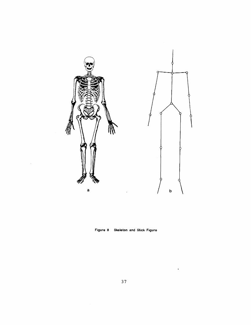
Figure 8 Skeleton and Stick Figure
37

consists of 24 vertebrae, a sacrum and a coccyx. A
wide variety of movements, twists, and deformations
possible through such an extensive array of bones make
a true body model extremely difficult to attain; one
must compromise by constructing the model as a series
of individual small rigid bodies.
This stick figure shown in Figure Bb models the
primary segments and joints in the body: pairs of feet,
lower legs, thighs, hips, shoulders, upper arms, lower
arms, and hands, and singly, the trunk, neck, and head.
This level of representation is enough to approximate
motion, yet not sufficent to show such subtleties as
hand gesture employing the fingers. Separate
"close-ups" are necessary to show such detail. Further
abstraction of the body's architecture is required to
devise an efficient data structure representing
relationships among the data.
The body may be divided into eight simple
components or SEGMENTS when considering motion
classification [20]. They are identified easily from
both the standpoints of anatomy and motion. Six come
in pairs; the feet, hands, lower legs, thighs, upper
arms, and the lower arms. The remaining two, the trunk
and the head-neck are treated as single segments when
identifying motion. When actually building a model,
the trunk and head-neck may be defined by several
segments, depending on the degree of articulation
38
desired.
Establishing a Reference System
In order to establish a system of classification
or movement notation one must establish a reference
system, analagous to the world coordinate system in 3d
graphics. There are two body postions which are
referred to as the standard or default positions within
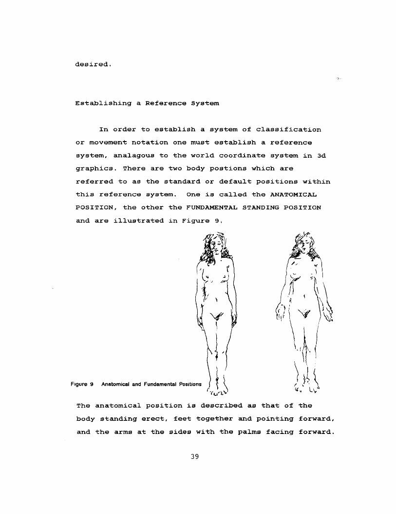
this reference system. One is called the ANATOMICAL
POSITION, the other the FUNDAMENTAL STANDING POSITION
and are illustrated in Figure 9.
Figure 9 Anatomical and Fundamental Positions e KThe anatomical position is described as that of the
body standing erect, feet together and pointing forward,
and the arms at the sides with the palms facing forward.
39
The fundamental position differs only in that the hands
are held with the palms facing the sides of the thighs.
Establishing a primary position is useful in
calibrating the relationships of the different body
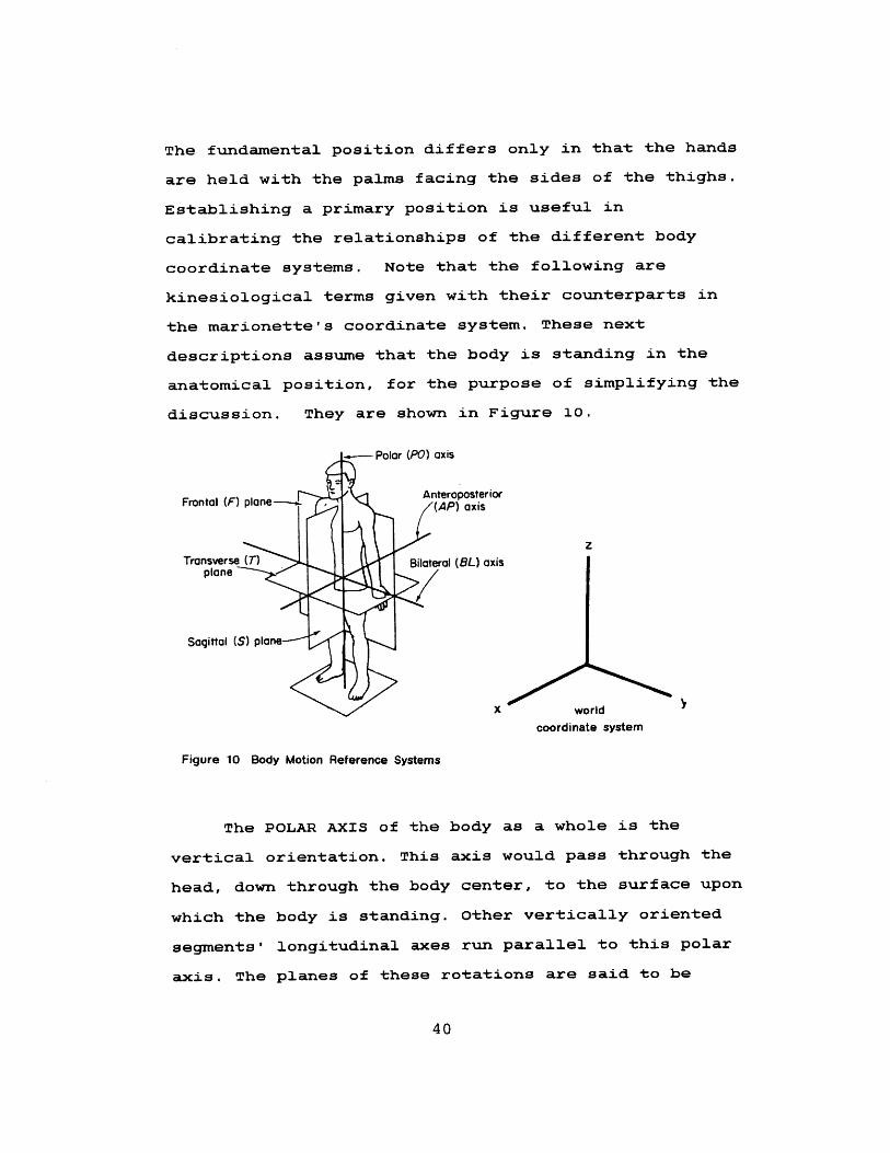
coordinate systems. Note that the following are
kinesiological terms given with their counterparts in
the marionette's coordinate system. These next
descriptions assume that the body is standing in the
anatomical position, for the purpose of simplifying the
discussion. They are shown in Figure 10.
Polar (PO) axis
Frontal (F) plane- Anteroposterior
zTransverse (T) Bilateral (BL) axis
plane
Sagittal (S) plane----
X worldcoordinate system
Figure 10 Body Motion Reference Systems
The POLAR AXIS of the body as a whole is the
vertical orientation. This axis would pass through the
head, down through the body center, to the surface upon
which the body is standing. Other vertically oriented
segments' longitudinal axes run parallel to this polar
axis. The planes of these rotations are said to be
40
parallel to the TRANSVERSE PLANE of the body as a whole.
This axis corresponds to the Z-AXIS in my world
coodinate system.
The BILATERAL AXIS is that which runs horizontal
relative to the supporting surface, and passing
sideways through the body. Imagine an axis drawn
through the left hip, center hip, then the right hip,
perpendicular to the polar axis. Horizontally oriented
joint axes run parallel to this axis. The planes of
motion about these axes are considered to be parallel
to the body's SAGITTAL PLANE. This axis corresponds to
the Y-AXIS in my world coordinate system.
The ANTEROPOSTERIOR AXIS is, like the bilateral
axis, horizontal, but runs from front to back through
the body. The horizontally oriented lengthwise axes of
the feet lie parallel to this axis. Rotation about
these axes are considered parallel to the body's
FRONTAL PLANE. The X-AXIS is the world coordinate
analogue of this axis. Most joint axes of the body in
the standard position are oriented horizontally,
parallel to the whole body's bilateral axis.
Now consider the body in motion. Most movements
are not so easily described as the simple orientations
of the anatomical position. For example, the elbow
flexion may occur parallel to any of the three planes.
Visualize the simple act of eating, of lifting a
41
forkful of food from plate to mouth. The shoulder,
elbow, wrist, and finger joints and related segments
move into positions which are far from being parallel
to the standard orientations. To further describe this
orientation in space, each segment has one or more AXIS
of ROTATION, exclusive to itself, as a part of the
general body database. Six variables specify position
(x,y,z) and orientation (#, e,4) of a segment in space;
it is therefore said to have six degrees of freedom
(DOF). The position and orientation of each segment in
relation to its neighboring segments' orientations
combine to create the innumerable complex motions of
the human figure.
Motion Classification Terminology
There are six basic segment movement classes:
FLEXION, EXTENSION, ABDUCTION, ADDUCTION, ROTATION, and
CIRCUMDUCTION. All but circumduction depend on rotatory
motion, in one of two ways. We can consider the body
segment as the "axis of rotation" in some cases (as in
a twisting motion), and in others it to be rotating
about an axis at one of its two ends, with the plane of
rotation traced through space by the segment itself. In
both cases the axis of rotation is perpendicular to the
plane of rotation, but not limited to one position in
space. Two of the previous terms are commonly used to
describe almost all of these classes of motion; FLEXION
42

covers about all bending motion, and ROTATION is used
to describe most segment orientations. Movements such
as flexion and extension nearly always refer to the
joint involved rather than the segment, whereas
rotation terminology refers to the segment(s) involved.
From Body to Binary Tree: The Data Structure
The sequence of rigid segments connected by joints
can be treated as a tree structure to describe the
body's connectivity. A convenient method for
expressing hierarchical structures such as the body, a
tree allows for a systematic processing of all the body
parts.
A tree is a nonlinear data structure which can be
viewed as a particular type of graph; a graph being a
representation of a system of connections or
relationships between a number of things. A GRAPH, G,
consists of a nonempty set V (the set of VERTICES), a
set E which is the set of EDGES, and a mapping from the
set of edges E to a set of pairs of elements of V [34].
There is at most one edge joining any pair of vertices.
A tree structure indicates a branching relationship
between its vertices, or NODES. Knuth defines a TREE
as a finite set T of one or more nodes such that
43

a) There is one specially designated node called the ROOT of
the tree, root(T); and
b) The remaining nodes (excluding the root) are partitioned
into m >= 0 disjoint sets TI,...,Tm, and each of these sets
in turn is a tree. The trees T1,....Tm are called the
SUBTREES of the root [21]
The LEVEL of a node is given as being its distance
from the root. Every node that is reachable from a node
N, is said to be a descendant of N. The nodes that are
reachable from that node N, through a single edge, are
called N's SONS. N can thus be referred to as their
FATHER. BROTHER nodes are those which are sons of the
same father. A node with no sons is called a TERMINAL
NODE or a LEAF. A tree TRAVERSAL or "tree walk" is a
procedure by which each node is visited in some
systematic fashion. The general tree structure can be
represented equivalently as a BINARY TREE. Knuth
defines a binary tree as "a finite set of nodes which
either is empty, or consists of a root and two disjoint
binary trees called the left and right subtrees of the
root." [21] This correspondence allows for a more
convenient computational representation of any tree,
and can be defined algorithmically. In contrast to the
way in which real trees grow, this structure is
visualized with the branches growing downwards from the
root. By studying the diagrams in Figure 11, one can
see the relationships of the components within a tree
structure, as well as that between a general and a
binary tree.
44
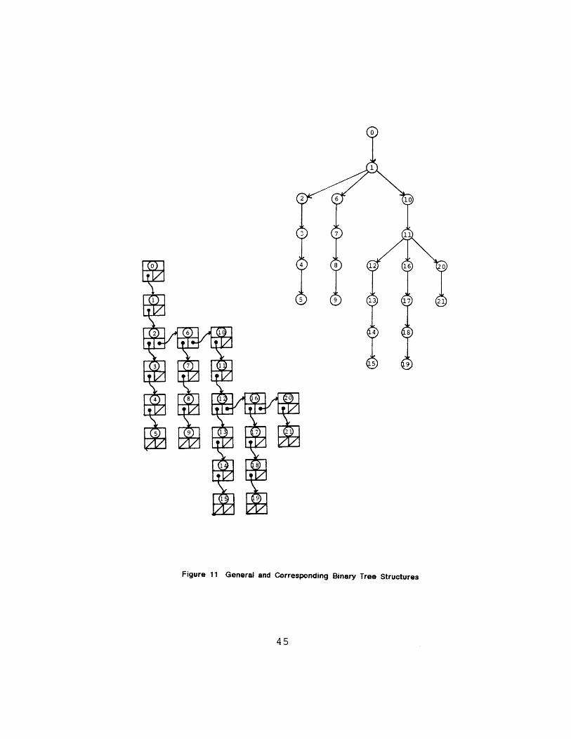
Figure 11 General and Corresponding Binary Tree Structures
45
worldcoordinate
system
2 V/112 root
x
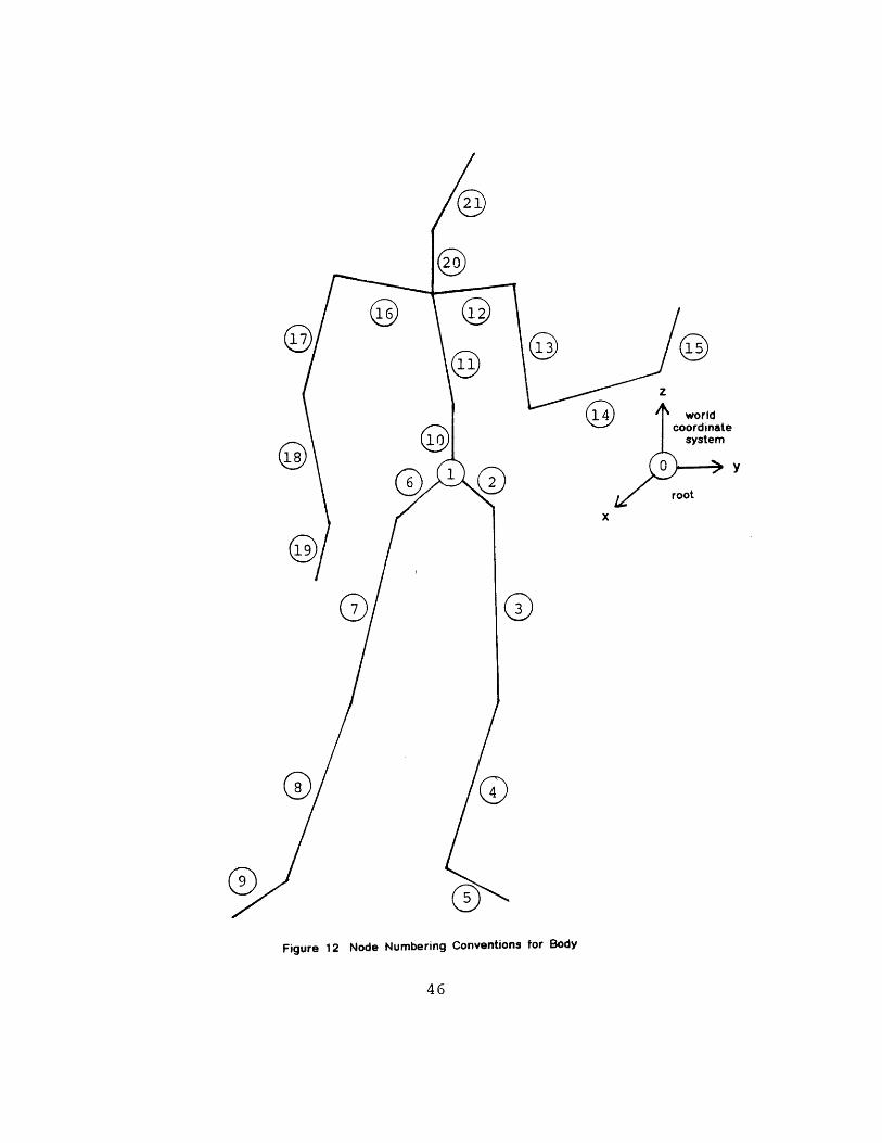
Figure 12 Node Numbering Conventions for Body
46
The numbering of the nodes in all of the body data
structures refer to the body segment names, rather than
the joint names. This is consistent with the motion
classification convention of rotation referring to the
segment(s) involved. This numbering begins with the
root node(O), which functions as a connection between
the world coordinate system and the center hip(l), and
continues as shown in Figure 12. When definining the
body's connectivity, the son and brother node are also
given. A "0" son or brother number indicates a leaf
node has been reached (i.e. the left and right subtrees
are null). The father's number is assigned at run time.
Traversing the "body tree" requires a STACK,
a linear list permitting the addition and deletion of
an element at one end. The addition process is called
PUSH, while the deletion is POP. The elements can be
removed only in the opposite order than the order in
which they were added; the bottom of the stack would
therefore be first element added, and the top the last
element added. A stack pointer keeps track of the top
element in the stack, and is incremented by one each
time a new element is added. To begin:
a) Initialize. Set stack pointer to 0, node to root
node number.
b) Check if the current node has a brother. If
there is one, push the brother onto stack and
47
increment the stack pointer by one.
c) Check if the current node has a son. If so, the
son now becomes the current node. Return to step
b and repeat until there are no more sons, then
proceed to step d.
d) Check the stack pointer to see if there are any
brothers waiting in the stack. If so, pop the
brother that is indexed by the pointer. This
becomes the current node.
Decrement the stack pointer by one, then return
to step b.
When all of the son and brother nodes have been visited,
the walk is complete.
components of the Body Data Base
The information for each body segment is
summarized as follows:
node number
name
current x-rotation
current y-rotation
current z-rotation
segment length
circumference
current 4x4 matrix(LTM)
48
son
brother
father
flag (bit(l))
Minimum and maximum rotation limits for each joint may
also be contained in this structure, but are not
essential at this point.
This data, although maintained as a single
structure at run time, is composed of a number of
smaller, related structures. Son and brother
information completely and flexibly specify the
connectivity of the body. Each segment has an
associated 4x4 matrix, controlling the motion of that
segment and its descendants, functioning much as the in
an actual limb would. The flag signals rotation
occurring at this joint so a new matrix will be
composed. The terms PROXIMAL and DISTAL are often used
to describe positions as "near" or "distant" from the
point of origin. Maximum and minimum extent of rotation
(current x,y,z) and translation (segment length), as
well as other anatomical constraints, may also be
stored in the data structure and used for error
checking and interpolation. The segment circumference
information is used later by the rendering programs.
Rotations in x, y, and z represent the rotational
transformation that the current segment must go through
such that its distal joint is contained in the z-axis
of the father's own local transformaton matrix (LTM).
49
The first rotation provides a twist around the previous
segment, the remaining two rotations line up the distal
joint with the z-axis. The segments' orientations
combine to create the innumerable complex motions of
the human figure. The LTM of a node represents the
history of all previous joint rotations and segment
translations plus the current rotations. Composing of
the LTM will be described shortly. The function of the
x, y, and z rotations are best understood in that
context.
Each segment exists in a coordinate system
embedded in its proximal end at 0,0,0. The z-axis
always points along the segment's longitudinal axis to
its distal end, which is also the proximal end of the
next segment. The distance between them is thus (0, 0,
length). When the body is standing in the anatomical
position, the positive x-axis points forward, and the
y-axis points in the direction that maintains a
right-handed coordinate system. In the case where the
z-axis points forward, as in the feet, the x-axis
points upward in relation to the whole body.
Composing the Transformation Matrix
The orientation of the distal joint of each
segment, saved as angles in the body data structure, is
described in relation to the father's coordinate system
50

after the latter has been translated along the father's
segment length. There must exist a composed
world-to-proximal-joint coordinate transformation that
causes the distal joint to be placed in the proper
relative orientation for subsequent rotation. Hence,
prior to actual operation on the current segment, the
current transformation matrix contains information
about all the relative rotations and translations of
the node's antecedents. To compose each local
coordinate system transformation matrix, independent of
any other segment, the operations are concatenated in
this order:
M[node] = identityjnat[node]
M' [node] = M[node] * rotxanat[node]
M' '[node] = M'[node] * roty.mat[node]
M'' '[node] = M' '[ node] * rotzjnat[node]
Me'''[node]= M ' ' '[node] * z_trans-mat[f ather]
In short: M' ' ' '[node] = rotx[node] * roty[node]
* rotz[node] * ztrans[father]
The world-to-proximal-joint transform is composed in
this order:
LTM[node] = M''' '[node] * LTM[father]
Matrix operations done in this order signify that
a coordinate system is being transformed, as opposed to
51
a point or set of points. The sequence can be thought
of as actually being performed from the last component,
backwards. The LTM is now updated by the current
angles and becomes the transformation matrix to be used
by the next node, that is, the son. In short, the
sequence for each segment is:
a) Orient to the father's coordinate system, with
proximal joint on the father's z-axis.
b) Translate the father's coordinate system to the
proximal joint.
c) Rotate about the z-axis.
d) Rotate about the y-axis.
e) Rotate about the x-axis.
f) Update to the new coordinate
system.
g) Draw the segment, using its limblength and other
associated data, in the new coordinate system.
Note that even though this allows us to visualize
each segment in its own coordinate system, the points
remain in the world coordinate system. Also, a
rotation of any given joint will affect the motion of
all of its descendants; if you move the shoulder, the
arm and hand are moved as well. Thus, a rotation of any
given joint will affect the motion of all of its
descendants (sons) -- if you move the shoulder, you
move the arm and hand as well. Segment/node [0]
connects the entire body to the world coordinate system.
52

Segment/node [1] is the center node of the entire body.
Both segments have a limblength of 0.
Rendering Programs
The initial body types are three: a stick figure,
a "cloud" figure composed of points distributed about
the longitudinal axes within ellipsoidal volumes, and a
handless and footless stick figure. The latter was
made specifically for the walk simulation program
described in Chapter Five. All of these provide simple,
quick visual feedback to the animator. Subsequent
"fleshed-out" models can be constructed from this
initial database after the animation has been scripted
and previewed.
Unfortunately, modelling the features of the body
is not a trivial task. Two techniques commonly used,
surface modelling and volume models both have certain
drawbacks, as mentioned in Chapter One. Some
experiments were done with volume models before
arriving at the current "cloud person". The ellipsoid,
out of all the simple volumes, appeared to be the shape
which best represented most of the parts of the human
form, but still appeared overstylized. By generating
points randomly within that volume, the ellipsoid shape
can be degraded enough so as to appear more like a limb,
that is, more irregular.
53
The first model used parametric representations of
an ellipse and a circle to generate the points about
the longitudinal axis [33]. "Circles of points" were
drawn at even intervals from the distal to proximal end
of each segment. A random number determined the radial
distance of the point between 0 (on the longitudinal
axis) and the maximum radius determined for that point
on the ellipse. Although efficient (a minimal number of
sine and cosine calculations), the circles of points
looked like horizontal slices through the body. (See
Figure 13)
In order to minimize this effect, the
distance along the z-axis, the distance about the
z-axis in degrees, and the radius were all multiplied
by a random number between 0 and 1. The result can be
seen in Figure 14 . The distribution of points may be
adjusted so that denser clustering along the
longitudinal axis gives the appearance of solid "bones".
color can also be regulated by the same distribution
function; the "bones" can be white, while the outer
points may be of some other darker color. The
advantages of using randomly distributed points are
mainly in the avoidance of both the hidden surface
removal computation normally used for solids and the
problem of holes or "singularities" occurring at
sharply bent joints.
54
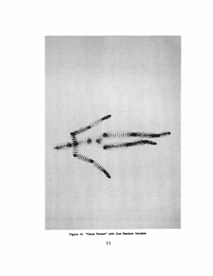
Figure 13 "Cloud Person" with One Random Variable
55
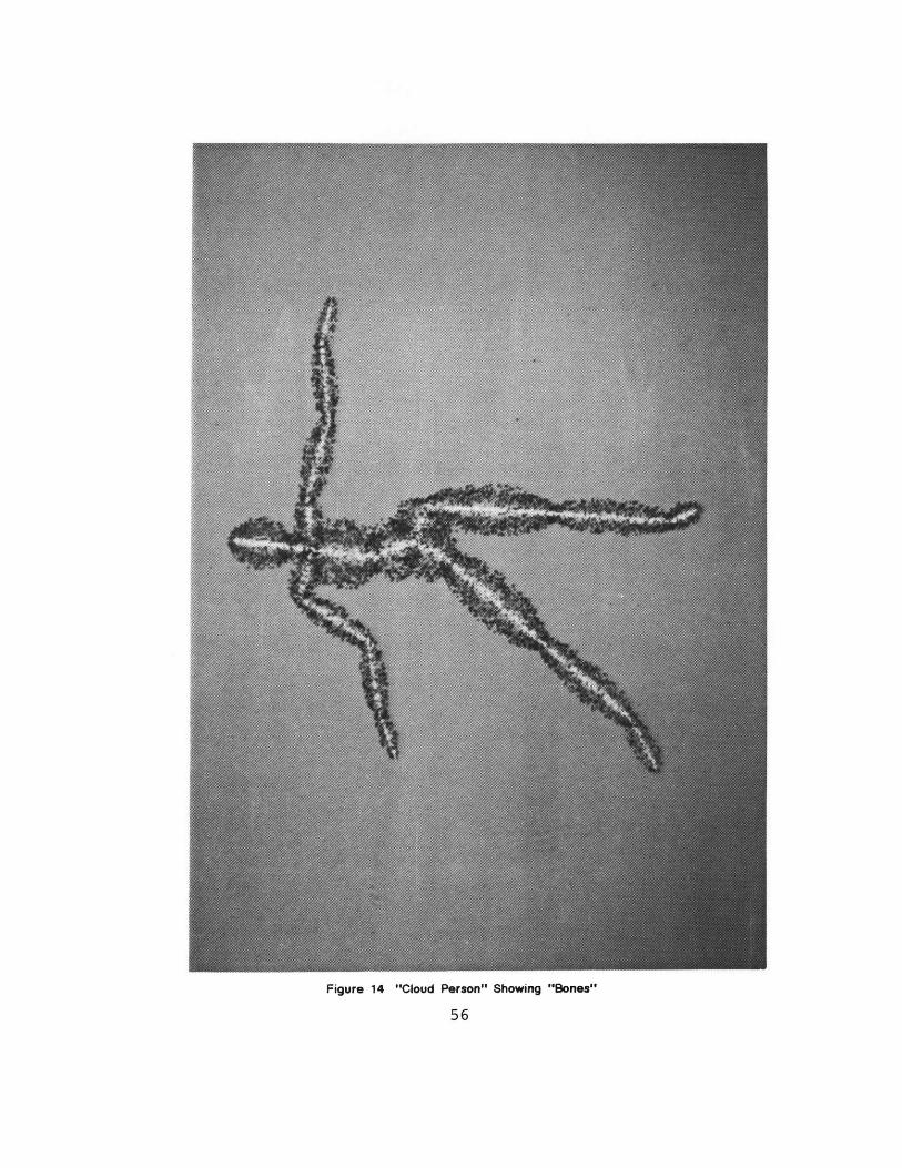
Figure 14 "Cloud Person" Showing "Bones"
56
The lengths of the body segments were obtained
from the Humanscale [14] survey, being the link
measurements of a fifty percentile female. These
dimensions only are useful as a general rule of thumb;
in rendering the body in diferent styles, one must
adjust the measurements. For example, to display a
stick figure of pleasing proportion, the shoulders must
be moved higher, the hips made wider, and the neck
shortened. This will help to account for the missing
bulk of muscles and flesh. For the cloud model, on the
other hand, the lengths of the feet, hands, and head
must be shortened to accomodate the extension of the
ellipsoid past the end of the segment. Segment
circumference, controlling the ellipsoid radius, must
also be adjusted until an aesthetic proportion is
achieved. The measurements for the body in the walk
simulation were obtained by algorithm generating
segments proportional to the torso, as is explained in
Chapter Five.
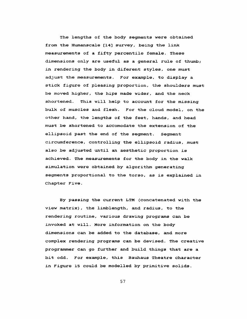
By passing the current LTM (concatenated with the
view matrix), the limblength, and radius, to the
rendering routine, various drawing programs can be
invoked at will. More information on the body
dimensions can be added to the database, and more
complex rendering programs can be devised. The creative
programmer can go further and build things that are a
bit odd. For example, this Bauhaus Theatre character
in Figure 15 could be modelled by primitive solids.
57
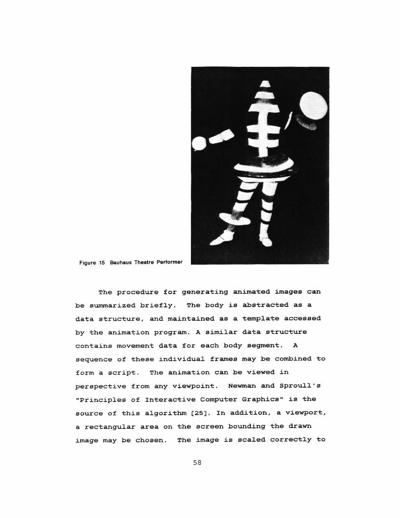
Figure 15 Bauhaus Theatre Pertormer
The procedure for generating animated images can
be summarized briefly. The body is abstracted as a
data structure, and maintained as a template accessed
by the animation program. A similar data structure
contains movement data for each body segment. A
sequence of these individual frames may be combined to
form a script. The animation can be viewed in
perspective from any viewpoint. Newman and Sproull's
"Principles of Interactive Computer Graphics" is the
source of this algorithm [25]. In addition, a viewport,
a rectangular area on the screen bounding the drawn
image may be chosen. The image is scaled correctly to
58
the dimensions of this viewport, and clipped if
necessary. Rendering programs are written as separate
and interchangeable modules. A stick figure, and
several variations on a volume model can be chosen.
These programs are written to be compatible with any
body model that has been created as a template. The
development of the animation programs is described in
greater detail in Chapter Five.
59-
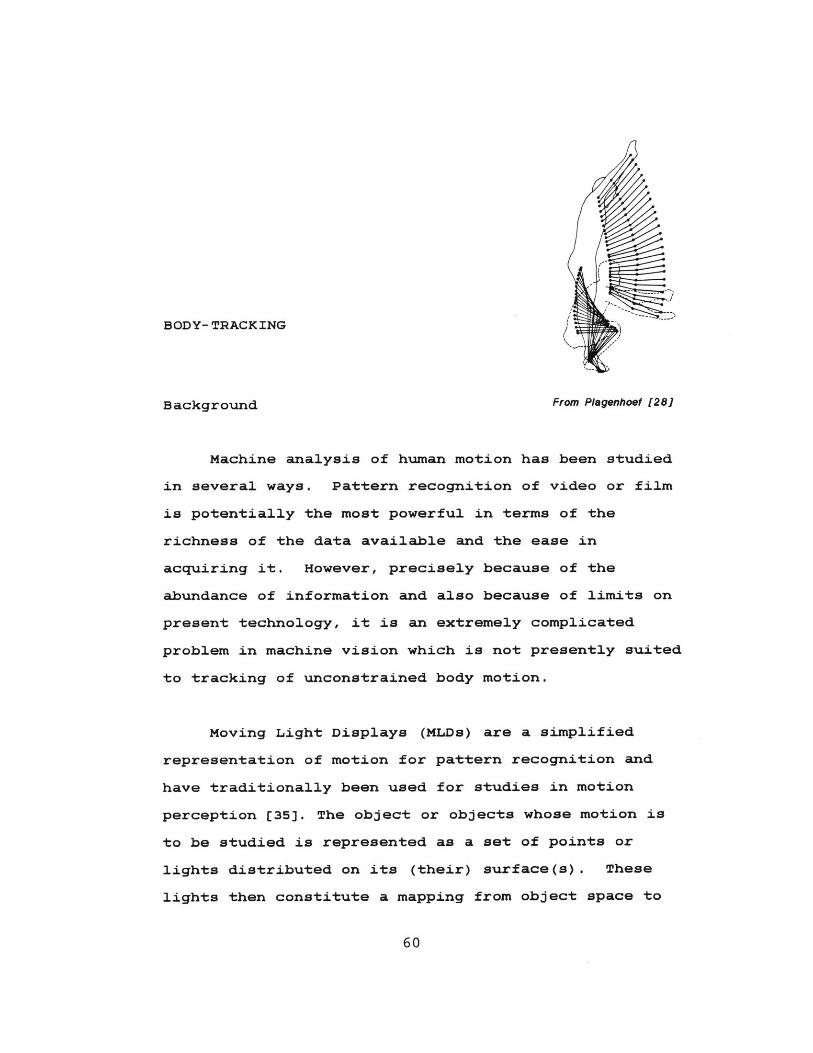
BODY- TRACKING
Background From Plagenhoef [281
Machine analysis of human motion has been studied
in several ways. Pattern recognition of video or film
is potentially the most powerful in terms of the
richness of the data available and the ease in
acquiring it. However, precisely because of the
abundance of information and also because of limits on
present technology, it is an extremely complicated
problem in machine vision which is not presently suited
to tracking of unconstrained body motion.
Moving Light Displays (MLDs) are a simplified
representation of motion for pattern recognition and
have traditionally been used for studies in motion
perception [35]. The object or objects whose motion is
to be studied is represented as a set of points or
lights distributed on its (their) surface(s). These
lights then constitute a mapping from object space to
60
image space and can be analyzed for motion as the image
varies over time. In the context of scripting-by-
enactment, the human subject, or scriptor, would wear a
set of continuously illuminated lights located at
strategic points. This amounts to parallel acquisition
of data which is presented as successive sets of dots,
each set representing a "snapshot" or frame of the
object in question. The problem in this case would be
to assign meaning to each dot within each frame. In
other words, correspondance must be established between
each dot of the captured image and points on the
surface of the object. This is a complicated yet
tractable endeavor but when two separate perspectives
and triangulation for depth information are required
then problems with speed, occlusion of lights and the
added correspondance factor all become severe [31]. It
then becomes unreasonable to track in three-dimensions
gross body movements with a flexible, array-of-lights
setup in real time at low cost.
Several products that illustrate other approaches
are available commercially, including the Polhemus, the
Coda-3, and the Selspot. The Polhemus system [7]
consists of a transmitting device, a sensing device,
and support software. The sensing device, attached to
a cord and worn by the subject, is a plastic cube into
which three mutually orthogonal coils are epoxied. The
transmitter radiates a nutating dipole field by which
the sensing cube is able to yeild six degrees-of-
61
freedom positional information. This type of tracking
has been tested on a smaller scale in a software
simulation of a Unimation Puma robot arm. The graphic
robot can be "taught" to move by a human trainer using
a Polhemus cube system in our Media Room [23]. Cubes
like this, with their cords, are unwieldy for total
body tracking, not to mention the fact that on the
order of thirty transmitting/ sensing sequences would
have to be multiplexed.
The Coda-3 is a device, not yet available in the
U.S., that provides remote and non-contacting means
of monitoring the movement of up to eight so-called
landmarks. It uses optical scanning to sweep three
fan-shaped beams of light across the field of view and
then senses the reflections from the landmarks. It is a
good, if costly, solution to the problem but the limit
of eight position indicators is too restrictive for
body-tracking as an animation tool.
In the Selspot system [12,22], the subject wears a
set of LEDs emitting in the infrared range which are
pulsed in sequence. Typically, thirty LEDs may be worn.
A camera which is sensitive primarily to these LEDs and
synchronized to them senses their projected position by
means of a two-axis lateral effect diode. Depth is
determined by triangulation from the output of two
cameras. This method of movement monitoring
corresponds to serial acquisition of the data and also
62
poses the most likely solution to body-tracking for
driving a graphical marionette. The Selspot is,
however, too restrictive in terms of the placement of
the LEDs and too expensive.
The application is tracking of gross body
movements for driving a body model. The Selspot
approach is a good place to start but is inappropriate
for several reasons. It is typically used in
situations, such as determining muscle forces, where
great precision is required. Lower resolution and
lower accuracy are tolerable in the present context and
even necessary to reduce costs and simplify processing
requirements. On the other hand, greater flexibility
is required in LED placement. The Selspot uses arrays
of LEDs which are strapped to the body segment. The
scriptor of the graphical marionette should be able to
don a comfortable, ready-to-wear garment. The point is
to enhance the human-machine interface, not complicate
it. Many more LEDs will have to be used to compensate
for the non-rigidity of the garment. This fact can be
used to advantage since many LEDs in the vicinity of
one body point may pulsed simultaneously, thus
constituting a "virtual point" and providing a brighter
light source. Unlike Selspot, domain specific
knowledge, i.e. body geometry and dynamics, may also be
used for error checking and interpolation.
The body-tracker should be automated, i.e. it
63
should require no operator intervention. It should
produce a set of position points (x,y,z) in real time
and provide visual feedback for the scriptor. It should
also be as unobtrusive as possible to the scriptor and
aim for portability in the sense of being adaptable for
use on a personal computer.
Developing the Body-Tracking Hardware
The heart of the body tracking system is a
two-axis lateral effect diode made by United Detector
Technologies (UDT). This optical sensor detects the
position of a spot of light on its surface.
Two-dimensional position information is then obtained
via four electrode connections at the edges of the
detector. The signals from these connections are fed to
an interface module, called the Op-Eye (UDT), where
they are amplified and digitized to 12 bits. The
output is compatible with an AppleII which then sends
the data to a Perkin Elmer 3230 after a certain amount
of low-level processing. The camera system uses
ordinary optics and does not require precise focus
since the detector senses the "centroid" of the light
spot on its surface. Motion is constrained to the
intersecting fields of view of two cameras. Both the
tracked LEDs and the photo-detector operate in the
infrared range so the system is relatively unaffected
by ambient light.
64
The prototype garment being developed is like a
lab coat. A suit will be devised or pants will be added
to enable tracking of the entire body. LEDs will be
distributed across the surface of the prototype garment
and fastened by piercing their leads through the fabric
and wire-wrapping the leads on the inside of the
garment. Wiring for the LEDs will thus be on the
inside and will be protected by a lining. Placement of
the LEDs will be on points corresponding to joints and
other bony prominences.
Control circuitry must be as portable as possible
so as not to encumber the wearer. No umbilical cord
would be necessary given an initialization sequence for
each "body-cycle". One is planned for now, however, so
that the sequencing of the LEDs can be done in a
flexible asynchronous manner, so that problems with
loss of synch can be avoided, and so that a standard
power supply can be used. Since each LED will be pulsed
individually, the LED wiring inside the garment is
forced to be in parallel. To minimize this wiring, a
decoding scheme can be employed. In this case, the LEDs
are divided into subgroups with the LEDs belonging to
each subgroup connected in parallel. Each subgroup
corresponds to a major subdivision of the human body,
like a leg-hip section, for instance. The master
controller is implemented with the AppleII and thus is
a separate unit located away from the scriptor.
65
The center frequency of the LEDs is such that it
matches the peak response of the cameras and such that
ambient light does not interfere. If necessary,
optical filters may be used to eliminate incandescent
sources. The diodes must operate with large included
angle between half-intensity points in order for the
camera to be able to detect them when they are at
various orientations in space. For a radiation angle
of 120 degrees, at least three LEDs must be used to
represent a joint such as an elbow. More LEDs are
actually needed since extra information helps offset
the difficulties encountered by using a loose-fitting
garment. More LEDs also yield a higher signal to noise
ratio at the detector. In this context, the spatial
averaging response of the detector is a feature which
is exploited. Since all the LEDs associated with one
joint are pulsed simultaneously, they do not, by
themselves, represent increased bandwidth. The Op-Eye
is capable of sampling at up to 5 KHz but the speed of
the overall system is much greatly reduced by the
present throughput limitations of the host (960 char/
sec).
The diodes must radiate with adequate intensity to
be detected by the cameras. They will be operated with
a very short duty factor, enabling them to handle a
large amount of instantaneous current. The Op-Eye's
sensing photodiode has a minimum detectable intensity
66
at its surface of 0.1 microwatts per square centimeter
which translates to a required minimum LED power in the
vicinity of 4 mW [16], considering optical parameters
and scripting space dimensions. The diodes used can
radiate on the order of 100 mW in derated situations.
Interfacing Hardware and Software
Upon transfer to the host, the data should first
be used as entries into a lookup table to correct for
non-linearities due to each camera. A calibration
routine using a fixed grid of light sources is required
to initialize the lookup table. The raw data are then
low-pass filtered. The resulting x-y coordinates from
each camera and corresponding to a particular LED are
to be used along with focal length information to
reconstruct by triangulation the position of the LED in
object coordinates. Occluded points may be inserted by
interpolation or neglected when feasible. All (x,y,z)
coordinates may be checked for errors on the basis of
past history and anatomical constraints Cl8).
The final points are conditioned for the animation
program and then passed to it. The points must be
mapped into a data structure compatible with the body
template, which are combined in the animation program
in the BODYDATA structure. The (x,y,z) points in world
coordinates are used to compute the orientation (in
67
degrees) of each segment in its own coordinate system.
The goal is to process an entire body's worth of
LEDs every thirtieth of a second, although the real
bottleneck is likely to be the animation program. At
this time, stick figures require approximately one
second per two frames to render, and a cloud model
requires from one to two minutes per frame, depending
upon the number of points needed for the model.
Optimization of the rendering routines can be
accomplished at a future date.
68
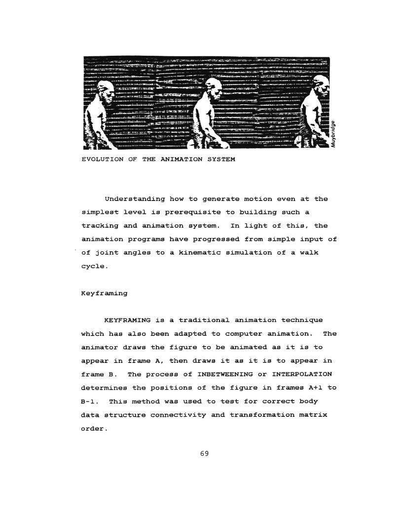
EVOLUTION OF THE ANIMATION SYSTEM
Understanding how to generate motion even at the
simplest level is prerequisite to building such a
tracking and animation system. In light of this, the
animation programs have progressed from simple input of
of joint angles to a kinematic simulation of a walk
cycle.
Keyframing
KEYFRAMING is a traditional animation technique
which has also been adapted to computer animation. The
animator draws the figure to be animated as it is to
appear in frame A, then draws it as it is to appear in
frame B. The process of INBETWEENING or INTERPOLATION
determines the positions of the figure in frames A+1 to
B-i. This method was used to test for correct body
data structure connectivity and transformation matrix
order.
69

Keyframe positions may be created and edited, then
stored in named data files. One of the editing
programs allows the animator to open any keyframe file,
change the angles at any node, draw it, and continue
until a satisfactory position has been reached. At
that time, it is written out. A SCRIPT can then be
made up of individual keyframes and the number of
inbetweens to be generated. One may view an animated
sequence by running a scripting program which does
simple linear in-betweening based on the (x,y,z)
rotation values at each joint. A synopsis of this
process for a sample move is given below. If you are
trying to generate values for the head angle between
frames 1 and 5, and the values for frames 1 and 5 were
o and 12 respectively, then you can say the following:
a) There are (finish-start-1) = 3 frames to
inbetween.
b) The total motion for this segment is
(head[5]-head[1]) = 12.
c) The motion for each step from one frame to the
next is
(head)5]-head[1])/ (finish-start) = 12/4 = 3.
d) For the n-th frame after the first frame, the
position is:
head(l] + n * ((head[5]-head(1])/ (f inish- start)).
e) The problem with this is that any error in the
increment (head[5]-head[1]) is multiplied
by larger and larger values of n. Alternately;
70
f) Compute and save the difference (head[5]-head[l]),
and compute the position as
head[l] + (head[5]-head[l]) * (n/ (f inish-start)).
g) n/(finish-start) can be thought of as the
percentage of the way between the start and
finish positions this frame (start+n) is in time.
Sequences showing both the stick figure and the
cloud person have been recorded on the write-once disc
and slides. For testing purposes, keyframing is
adequate, and provides the animator with visual
feedback. However, there are several drawbacks to this
method. It generates motion which is too uniform to
look natural; human motion consists of numerous
parallel and uneven movements. It is possible to use
some other method than linear interpolation to define a
space curve, such as B-splines, but timing is still
problematic. Also, trying to move the figure by joint
angle input for 22 nodes is slow and non-intuitive for
an animator. The effects of multiple rotations in
3-space are hard to predict unless one is thoroughly
familiar with this method. Figure 16 shows the result
of a keyframe script.
A walk Simulation
For the purposes of system development and testing,
an algorithm that generates synthetic walkers was
71
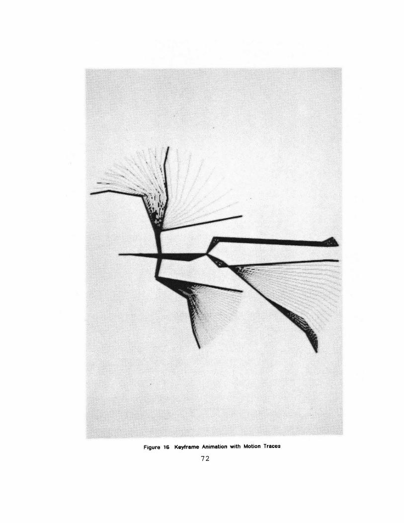
I
Figure 16 Keyframe Animation with Motion Traces
72
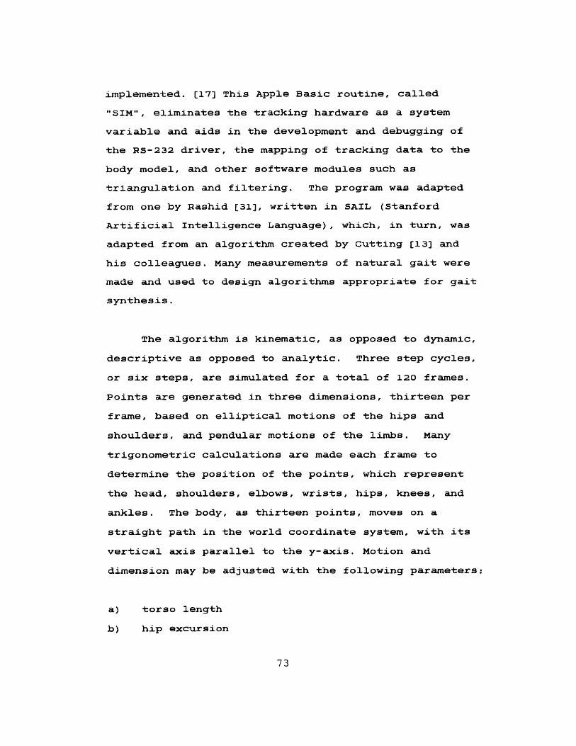
implemented. [17] This Apple Basic routine, called
"SIM", eliminates the tracking hardware as a system
variable and aids in the development and debugging of
the RS-232 driver, the mapping of tracking data to the
body model, and other software modules such as
triangulation and filtering. The program was adapted
from one by Rashid [31], written in SAIL (Stanford
Artificial Intelligence Language), which, in turn, was
adapted from an algorithm created by Cutting [13] and
his colleagues. Many measurements of natural gait were
made and used to design algorithms appropriate for gait
synthesis.
The algorithm is kinematic, as opposed to dynamic,
descriptive as opposed to analytic. Three step cycles,
or six steps, are simulated for a total of 120 frames.
Points are generated in three dimensions, thirteen per
frame, based on elliptical motions of the hips and
shoulders, and pendular motions of the limbs. Many
trigonometric calculations are made each frame to
determine the position of the points, which represent
the head, shoulders, elbows, wrists, hips, knees, and
ankles. The body, as thirteen points, moves on a
straight path in the world coordinate system, with its
vertical axis parallel to the y-axis. Motion and
dimension may be adjusted with the following parameters:
a) torso length
b) hip excursion
73

c) shoulder excursion
d) step size
e) speed
All the limb lengths are keyed to the torso length,
i.e., changing the torso simply scales the body. The
hip and shoulder excursions affect the appearance of
the figure, particularly on the basis of gender.
Varying the step size and speed alters the quality of
the motion. The body's forward lean increases with
speed, as do the extent of arm and leg swing.
The present implementation is different from
Cutting's in that no account is made of the occlusion
of lights as the figure moves. The SIM program models
the figure as transparent.
As created by the algorithm, the frames occur at
even angular intervals of the swinging limbs, not even
intervals of time. The synthetic gait data is
generated off-line and played back with an assembly
language program optimized for speed.
SIM creates a file of world coordinate data out of
120 frames; the data is then shipped out through the
serial interface to the host computer. Although the
SIM program was written in Basic to run on the Apple,
it could just as well have been implemented on the host,
with the resulting data sent back to the Apple which
74

would then, in turn, simulate the original process of
sending out the data itself, the point being to
approximate the flow of the data as it would occur
during normal operation of the body-tracker.
The SIM data file is used, in one application, to
animate the tree-structured body model. It eliminates
the need for keyframing and inbetweening, and is a good
approximation of where the lights will be placed on the
LED suit.
Three initial incompatibilities exist. In the
first place, both the SIM and body-tracking data
correspond to virtual points, or joints, while the body
model uses nodes with segments that have non-zero
length. Secondly, data from the body-tracker are in
the form of cartesian coordinates, yet the tree
structure uses angular data. One is a problem in
mapping structure, the other in mapping data. Lastly,
the dimensions of the two world coordinate spaces are
dissimilar.
The first issue is resolved by creating a
one-to-one correspondance between joints from SIM and
segments from the body model. A potential for
confusion lies in the fact that every segment is
bounded by two joints, but if each segment is paired
with its distal joint, as illustrated in Figure 17,
then the mapping becomes unique and one-to-one.
75
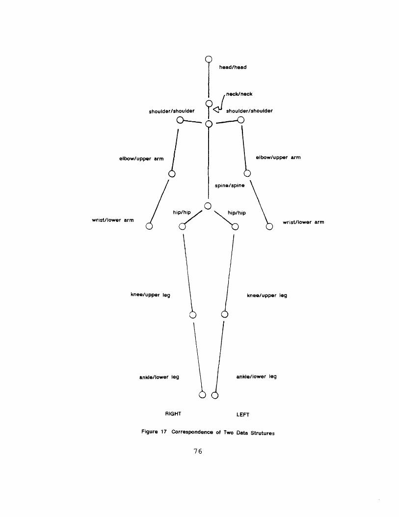
shoulder/shoulder
elbow/upper arm
wrist/lower arm
hip
knee/upper leg
ankle/lower leg
RIGHT
head/head
Iupper arm
spine/spine
hip/hip
wrist/lower arm
knee/upper leg
ankle/lower leg
LEFT
neck/neck4
Figure 17 Correspondence of Two Data Strutures
76
J shoulder/shoulder
elbow/
In the second case, it is necessary to "walk the
tree" in order to maintain compatibility with the
existing programs; angles calculated relative to the
previous segments are required. The current state of
each coordinate system must be saved for subsequent use.
Scaling from the SIM coordinate system to the
marionette coordinate system alleviates the third
problem.
After transfer from the Applell, the coordinate
data exists as a text file. It is first read in,
transformed so as to be oriented correctly in the new
coordinate system, and then scaled to be consistent
with the dimensions of the modelling system. For each
frame, the top and base of the spine are determined as
averages of the shoulders and hips, respectively, and
then a "center shoulder" and a "center hip" are created
by parametrizing along the spine. This will give the
stick figure a more realistic appearance, as if it has
a clavicle and pelvis. Next, the order of points is
unscrambled and made consistent with the node numbering
in the body charcteristics template creation program.
Also, the center hip location in world coordinates is
saved for later use, and the points are translated so
that the center hip is at the origin. Finally, the
limb lengths in the template program are set according
to the lengths established in SIM and from saved
parameter data used to create the center shoulder and
77
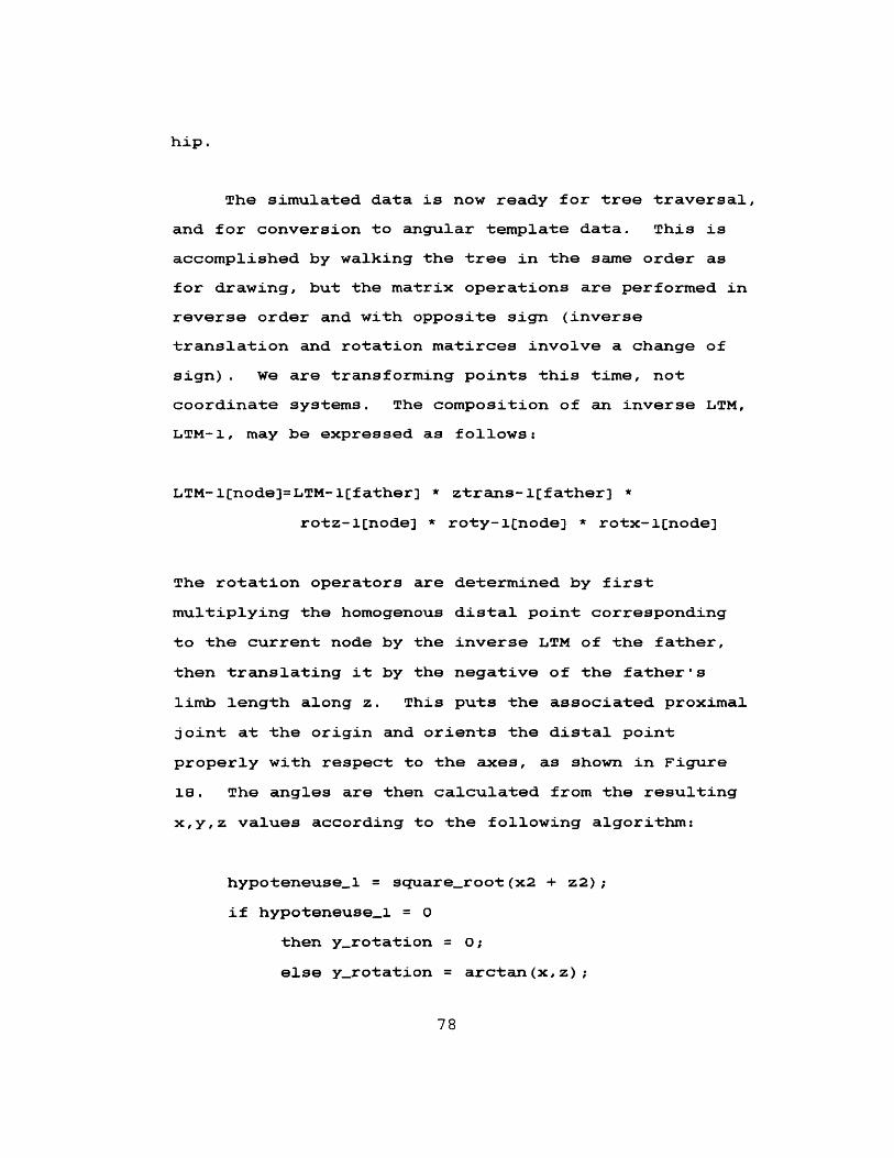
hip.
The simulated data is now ready for tree traversal,
and for conversion to angular template data. This is
accomplished by walking the tree in the same order as
for drawing, but the matrix operations are performed in
reverse order and with opposite sign (inverse
translation and rotation matirces involve a change of
sign). We are transforming points this time, not
coordinate systems. The composition of an inverse LTM,
LTM-1, may be expressed as follows:
LTM- 1[node]= LTM- l[father] ztrans-l[father] *
rotz-l[node] * roty-l(node] * rotx-l[node]
The rotation operators are determined by first
multiplying the homogenous distal point corresponding
to the current node by the inverse LTM of the father,
then translating it by the negative of the father's
limb length along z. This puts the associated proximal
joint at the origin and orients the distal point
properly with respect to the axes, as shown in Figure
18. The angles are then calculated from the resulting
x,y,z values according to the following algorithm:
hypoteneuse_1 = squareroot (x2 + z2);
if hypoteneuse_1 = 0
then yrotation = 0;
else y-rotation = arctan(x,z);
78
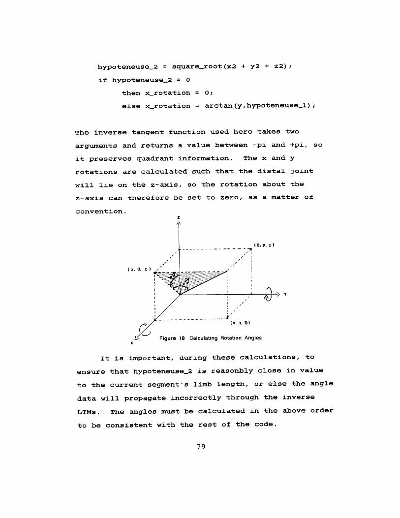
hypoteneuse.2 = square-root (x2 + y2 + z2);
if hypoteneuse_2 = 0
then x-rotation = 0;
else x-rotation = arctan(y,hypoteneuse-1) ;
The inverse tangent function used here takes two
arguments and returns a value between -pi and +pi, so
it preserves quadrant information. The x and y
rotations are calculated such that the distal joint
will lie on the z-axis, so the rotation about the
z-axis can therefore be set to zero, as a matter of
convention.z
(x,0, z ))
((x, 0, D)
AA
.- Figure 18 Calculating Rotation Anglesx
It is important, during these calculations, to
ensure that hypoteneuse_2 is reasonbly close in value
to the current segment's limb length, or else the angle
data will propagate incorrectly through the inverse
LTMs. The angles must be calculated in the above order
to be consistent with the rest of the code.
79
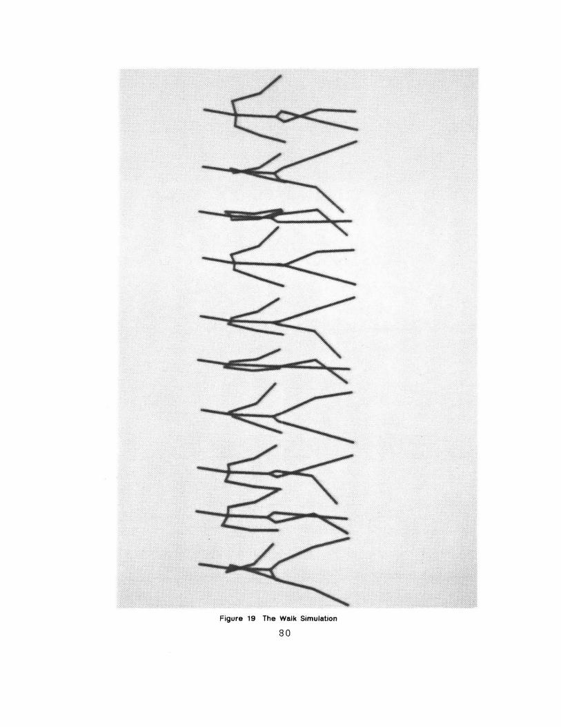
Figure 19 The Walk Simulation
80
An image illustrating stick figure motion is shown
in Figure 19. As can be seen, the orientation of the
limbs is more kinesiologically correct than that
created by hand, and thus appears more lifelike.
Underconstrained Systems
If a system has more degrees of freedom than the
number of imposed constraints, then it is said to be
"underconstrained". When considering the motion of the
human form, several difficulties arise in specifying
completely the positions of the body segments.
During the initial stages of body-tracking
development, a limited number of LEDs will be
operational. Here arises the problem of missing data
for certain joints. Even given a fully developed
system, one encounters the problem when one body part
may pass behind another, thereby occluding the LEDs
completely for a period of time.
Consider the problem of finding the position of
the elbow (B), given the location of the shoulder joint
(A), and the wrist (C). Here the wrist and shoulder
would be constrained by the given positions, and the
elbow represents the extra degree of freedom.
Another variation would be missing data at (C).
81
This is shown by the body model used in the walk
simulation, where the stick figure lacks hands and feet.
Without the position of the distal end of the final
segment, the orientation of the proximal joint can't be
determined.
Many segments, such as the lower arm, are capable
of "twist" about its' own z-axis. The limits of such
twist are defined anatomically, as listed in Appendix B.
Defining the direction of the segment during motion
presents a problem because of the ambiguity of
orientation. Body-tracking will not necessarily
alleviate the difficulty, especially if the LEDs are
placed symmetrically about a segment. Badler [3]
proposes a "standard orientation" function, based on
observations about certain orientations at given
positions being more natural than others; indeed, given
rotation limits, some orientations are anatomically
impossible. The standard or default orientation is
defined at each possible position of the limbs. When a
segment is moved into a new position, the resulting
orientation is computed (the orientation generally
depends on the path used to reach the given position).
This is compared to the standard orientation and
adjusted if necessary.
The solution to these problems is beyond the scope
of this thesis, but will constitute an important topic
for future research. Some data available currently in
82
the database provides a starting point for tackling
this problem. The limits of rotation for each segment
are maintained in the body data structure, and segment
lengths are fixed. Given the locations of two joints,
A and C, finding B is a matter of choosing a best
solution from two loci of points formed by the
segments' possible paths. The path of a locus of
admissible points forms a circle, or part thereof,
depending upon the angular limits on rotation.
In the case of temporarily occluded points, it may
be more useful to also use the history of the preceding
trajectory to determine a range of admissible positions.
Development of the tools for "scripting-by-
enactment" has progressed in stages. Program modules
were tested individually, then combined to to create a
compatible interface. The system is now capable of
animating figures using simulated data in the same way
that the actual tracking data will be handled.
continued parallel development of hardware and software
will help to solve the complex problems of portraying
the human figure in motion.
83
Then, following eternal norma,
You move through multitudinous forms
To reach at la8t the stale of man.
Goethe, FAUST Part Two
SUMMAT ION
Extensions and Improvements
The "cloud person" is seen as a viable method of
portraying the human from, especially in view of a few
adjustments that will enable the marionette to gain
some semblance of character. The first will be to
illuminate the figure given a light source. The next
step is to "sculpt" more detailed features which can be
accentuated by this new capability to portray light and
shadow. The most interesting case in point is the head.
A further control of the radial distance from the
longitudinal axis, corresponding to such real distances
on the head, could effectively model features such as
the eyes, nose, and mouth. Even such sparse information
will be enough to create recognizable images.
Less visible yet useful improvements are now
planned. The interactive screen editor used to create
and preview keyframes is being extended so that body
84
data structures may be edited quickly. Changes such as
body segment lengths and circumferences can be changed
and verified using a similar editor. Currently under
consideration is a generalization of the body data
structures. The new hierarchy of class (humans,
spiders), variations within that class (male,female),
and motion data files and scripts related to each class
will automatically prevent data files of the wrong size
and type to be initiated in an animation program. This
idea is based on the hierarchies familiar to us from
biology studies; phylum, class, order, family, genus,
and species. All of the sub-categories can refer to
the class structure to reference names and node numbers,
thus eliminating duplication.
Future Animation Scenarios
During the scripting process, the stick figure
will serve as feedback to the animator. once satisfied
with a motion sequence, the animator may save this
script for a later playback with a marionette
"fleshed-out" as a solid figure. An extension of the
scripting-by-enactment technique will be its
application to scenes requiring more than one
marionette performing in a sequence, or perhaps within
a certain virtual environment - that is,
"scripting-in-context" [6].
85
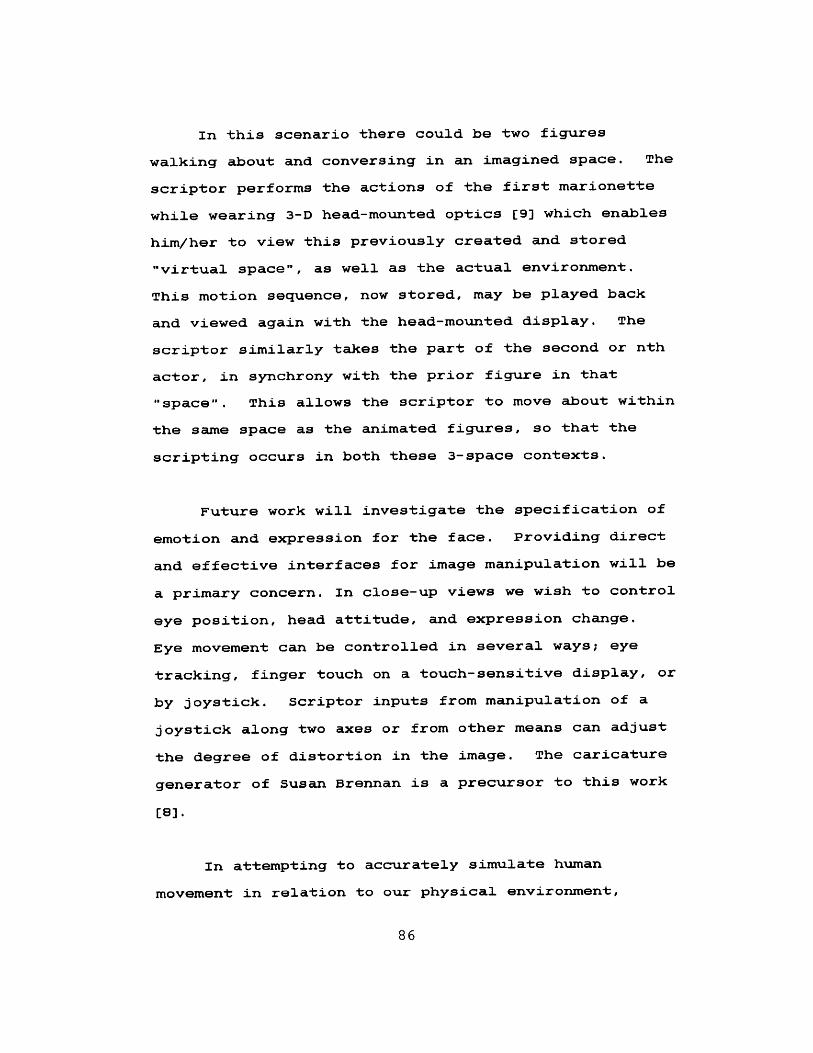
In this scenario there could be two figures
walking about and conversing in an imagined space. The
scriptor performs the actions of the first marionette
while wearing 3-D head-mounted optics [9] which enables
him/her to view this previously created and stored
"virtual space", as well as the actual environment.
This motion sequence, now stored, may be played back
and viewed again with the head-mounted display. The
scriptor similarly takes the part of the second or nth
actor, in synchrony with the prior figure in that
"space". This allows the scriptor to move about within
the same space as the animated figures, so that the
scripting occurs in both these 3-space contexts.
Future work will investigate the specification of
emotion and expression for the face. Providing direct
and effective interfaces for image manipulation will be
a primary concern. In close-up views we wish to control
eye position, head attitude, and expression change.
Eye movement can be controlled in several ways; eye
tracking, finger touch on a touch-sensitive display, or
by joystick. Scriptor inputs from manipulation of a
joystick along two axes or from other means can adjust
the degree of distortion in the image. The caricature
generator of Susan Brennan is a precursor to this work
[8].
In attempting to accurately simulate human
movement in relation to our physical environment,
86
complex modelling systems have been devised. For the
purpose of animation, such completeness is perhaps less
important than the model's characterization and
appearance, and ease in animation. our focus here is
on those concerns. Since the marionette figure uses a
generalized jointed figure database, its application is
not restricted to human animation. One could
conceivably envision a scenario with dragons or robots
or insects, employing similar types of databases for
their definition. Imagine guiding the trajectory of a
bee in flight by tracking the motion of the hand!
The technique of scripting-by-enactment is being
pursued as a more natural method for animation
scripting. It will also aid in constructing parallel
motions, one of the unwieldy aspects of computer
animation. Actions in a virtual 3-D world can be the
consequences of motion performed in the user's 3-D
world. More sophisticated modelling programs will aid
in yielding realistic animation of artificial
characters. The graphic "Doppelganger", able to "do as
I do, and not as I type" is the goal.
87
APPENDIX A:
A BRIEF USER'S MANUAL
Coordinate System Conventions
The world coordinate system itself is defined as
having the positive z-axis pointing up, the positive
y-axis pointing right, and the positive x-axis pointing
outward from the display screen, making it a
right-handed system. 0,0,0 is located in the center of
the screen as the default position. The orientation of
the z-axis is reversed while composing the viewing
matrix. (The left-handed eye coordinate system in
Newman and Sproull). All rotations are thought of as
clockwise when looking along the positive rotation axis
toward the origin.
Viewing Parameters
The figure may be viewed from any viewpoint. You
specify a look from point, using one of two programs
(view-globe.pll or viewxyz.pll). View-globe requires
the viewpoint to be specified as a longitude, latitude,
and variable radius, as if the eye were located on a
sphere. View-xyz is given in x,y,z coordinates, in the
world coordinate system. The viewbox matrix specifies
the perspective transformation, and provides clipping
88
limits for the hither and yon planes. It is usually
set at (1., 100.,2.), but can be altered to change the
perspective effects. The viewbox matrix is concatenated
with the viewing matrix. You can also specify a
viewport, a rectangular area on the screen, given in
device (Ramtek) coordinates. Your figure will be mapped
into that area on the screen. As in the world
coordinate system, I prefer to think of 0,0 as being in
the lower left hand corner.
Matrix Utilities
The matrices$ program is based on the existing
matrix routines which handle matrix multiplication for
3d transforms (scaling, rotation, translation). The
usual convention is to pass a matrix and the
corresponding arguments. The new transformed matrix is
passed back to the calling program. There should be
on-line documentation -- try "help matrix."
Program Use
This section of Graphical Marionette documentation
explains briefly how to run programs from the directory
u>delle> body. In addition, each program is listed
with a description containing the following: input,
arguments, how declared and called, and which other
89
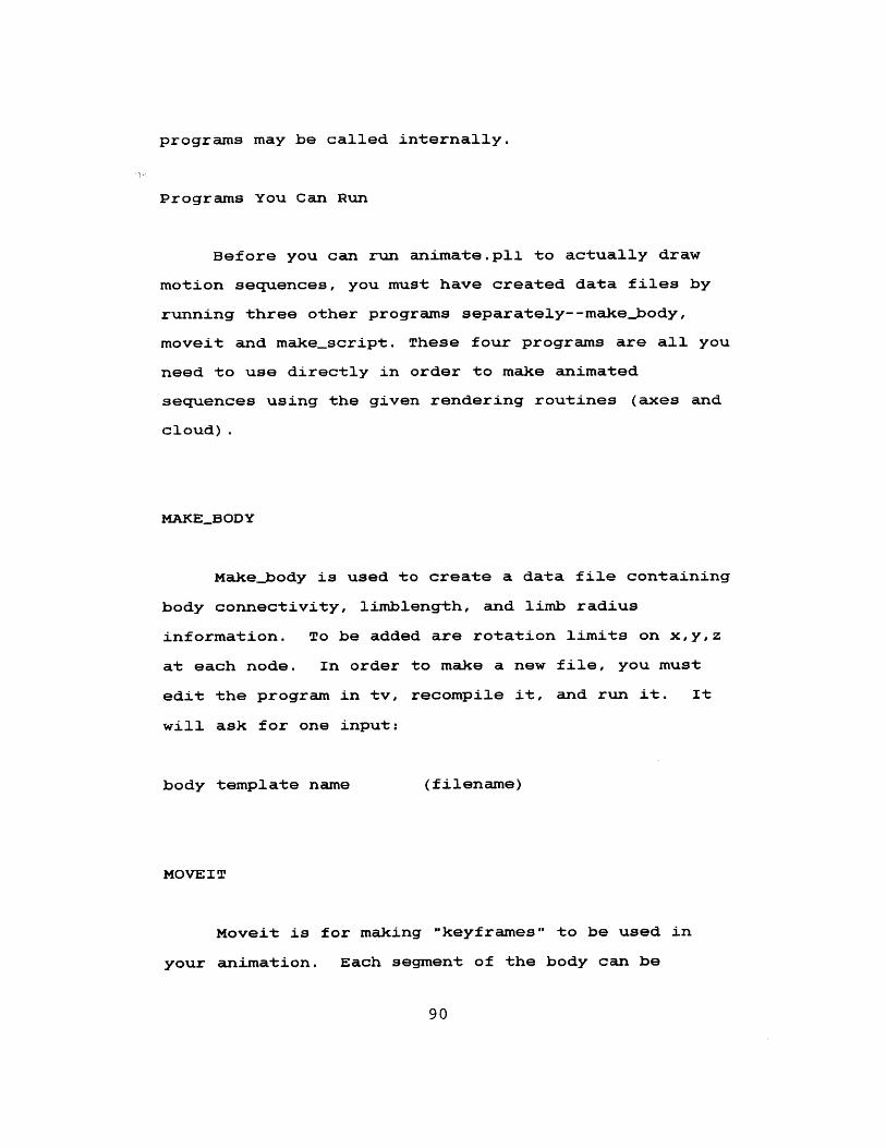
programs may be called internally.
Programs You Can Run
Before you can run animate.pli to actually draw
motion sequences, you must have created data files by
running three other programs separately--makebody,
moveit and make-script. These four programs are all you
need to use directly in order to make animated
sequences using the given rendering routines (axes and
cloud).
MAKEBODY
Make-body is used to create a data file containing
body connectivity, limblength, and limb radius
information. To be added are rotation limits on x,y,z
at each node. In order to make a new file, you must
edit the program in tv, recompile it, and run it. It
will ask for one input:
body template name (filename)
MOVEIT
Moveit is for making "keyframes" to be used in
your animation. Each segment of the body can be
90
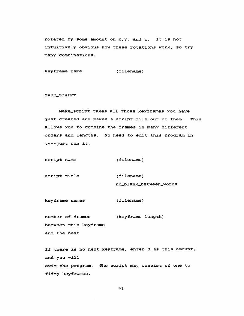
rotated by some amount on x,y, and z. It is not
intuitively obvious how these rotations work, so try
many combinations.
keyframe name (filename)
MAKESCRIPT
Makescript takes all those keyframes you have
just created and makes a script file out of them. This
allows you to combine the frames in many different
orders and lengths. No need to edit this program in
tv--just run it.
script name
script title
keyframe names
number of frames
between this keyframe
and the next
(filename)
(filename)
noblankbetween_words
(filename)
(keyframe length)
If there is no next keyframe, enter 0 as this amount,
and you will
exit the program. The script may consist of one to
fifty keyframes.
91

NOTE: Using descriptive filenames may aid in keeping
track of
which is which, until the more sophisticated data
structures are implemented.
ANIMATE
Now you should be ready to run animate, which is
much more useful than one_frame. Animate asks for ten
inputs:
viewport
limits
(lowx, lowy, highx, highy)
Remember that I define the viewport as
having 0,0 at the lower left corner, and
that these limits are in screen
coordinates.
viewpoint (longitude, latitude, radius) or (x,y,z)
depending on whether you use
lookfromglobe
or lookfromxyz.
drawing style
style
cloud.pl.
bodydata
script
(style number)
(1) calls axes.pll, and (2) calls
(filename)
(filename)
92
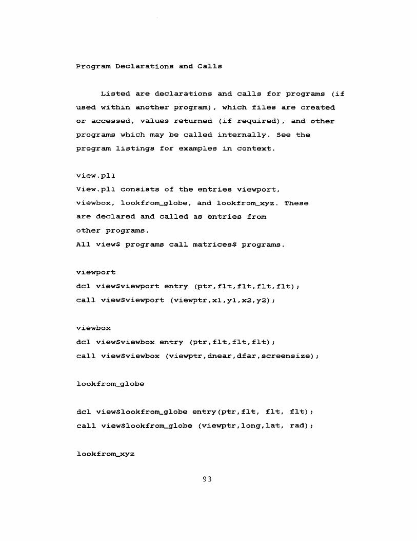
Program Declarations and Calls
Listed are declarations and calls for programs (if
used within another program), which files are created
or accessed, values returned (if required), and other
programs which may be called internally. See the
program listings for examples in context.
view.pli
View.pll consists of the entries viewport,
viewbox, lookfrom-globe, and lookfrom-xyz. These
are declared and called as entries from
other programs.
All viewS programs call matrices$ programs.
viewport
dcl viewSviewport entry (ptr,flt,flt,flt,flt);
call viewSviewport (viewptr,x1,yl,x2,y2);
viewbox
dcl viewSviewbox entry (ptr,flt,flt,flt);
call view$viewbox (viewptr,dnear,dfar,screensize);
lookfromglobe
dcl view$lookfrom-globe entry(ptr,flt, flt, flt);
call viewlookfrom.globe (viewptr,long,lat, rad);
lookfrom-xyz
93
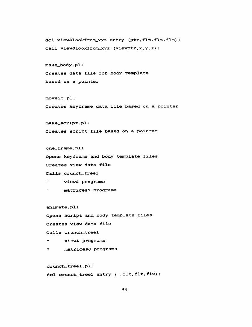
dcl view$lookfrom-xyz entry (ptr, flt, flt, flt);
call viewSlookfrontxyz (viewptr, x, y, z);
make-body. p11
Creates data file for body template
based on a pointer
moveit.pli
Creates keyframe data file based on a pointer
make-script.pl
Creates script file based on a pointer
oneframe.pll
opens keyframe and body template files
Creates view data file
Calls crunchtreel
"t views programs
"t matrices$ programs
animate.pli
Opens script and body template files
Creates view data file
Calls crunch-treel
"t views programs
"o matricess programs
crunch-treel.pll
dcl crunchtreel entry ( ,flt,flt,fix);
94
call crunch-treel
(body-data,viewmat,viewportmat,stylenum);
Calls axes
"f cloud
"o matrices$ programs
axes.pl1
dcl axes entry (flt,flt,flt);
call axes (limblength,finalmat,viewportmat);
Calls clip-draw
"e matrices$ programs
cloud.pli
dcl cloud entry (flt,flt,flt,flt);
call cloud
(limblength,radius,finalmat,viewportmat);
Calls clip-draw
"o matrices$ programs
clip-draw. pli
dcl clip-draw entry (flt,flt,flt,fix);
call clip-draw (ptsl,pts2,viewportmat,color);
Calls matrices$ programs
matrices.pl1
Utility programs for matrix operations
are written as entries in matrices. They
return some value(s) to the calling program.
Anything named mat, mati, mat2, oldmat, or newmat
95
is assumed to be a 4x4 matrix.
Pts is assumed to be a 1x4 array.
ident
dcl matrices$ident entry (flt);
call matricesSident (mat);
Returns mat
trans
dcl matricesStrans entry (flt,flt,flt,flt);
call matrices$trans (mat,tx,ty,tz);
Returns mat
scale
dcl matrices$scale entry (flt,flt,flt,flt);
call matrices$scale (mat,sx,sy,sz);
Returns mat
rotx
dcl matricesSrotx entry (flt,flt);
call matricesSrotx (mat,radians);
Returns mat
roty
dcl matrices$roty entry (flt,flt);
call matrices~roty (mat,radians);
Returns mat
rotz
96
dcl matricesSrotz entry (flt,flt);
call matrices$rotz (mat,radians);
Returns mat
concatenate
dcl matrices$concatenate entry (flt,flt);
call matrices$concatenate (matl,mat2);
Returns mati
new
dcl matrices~new entry (flt,flt);
call matricesSnew (pts,mat);
Returns pts
copyT
dcl matrices$copyT entry (flt,flt);
call matrices$copyT (newmat,oldmat);
Returns newmat
dcl matricessprint entry (flt,char(32)vary);
call matrices$print (mat,matname);
print_flt
dcl matrices$print_flt entry (flt,char(32)vary);
call matrices$print_f lt (mat,matname);
Calls ioa-flts
-I ioan_flts
97
ioa-flts.pll
dcl ioa-flts entry (flt);
call ioa-f its (var);
ioanf lts . pll
dcl ioanflts entry (flt);
call ioanflts (var);
bod.cm
Color matrix used with these programs
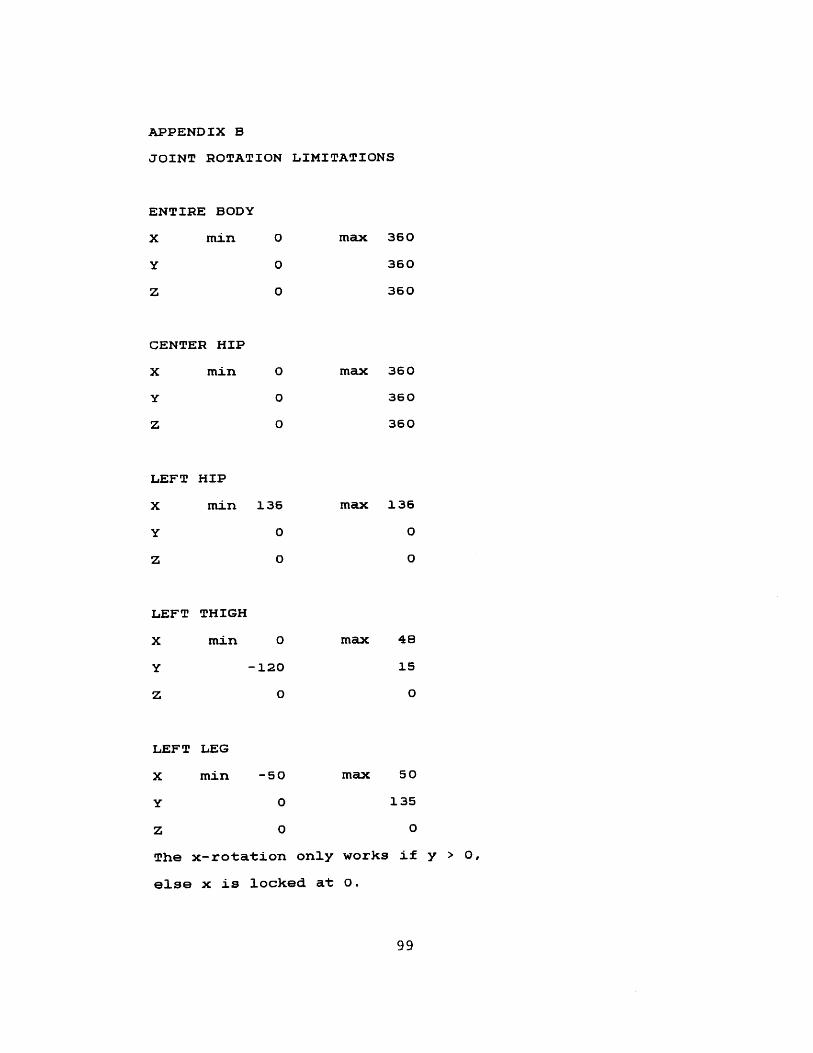
APPENDIX B
JOINT ROTATION LIMITATIONS
ENTIRE BODY
X min
Y
z
CENTER HIP
X min
Y
z
0
0
0
0
0
0
LEFT HIP
X min 136
Y 0
z 0
LEFT THIGH
X min 0
Y -120
z 0
max 360
360
360
max 360
360
360
max 136
0
0
max 48
15
0
LEFT LEG
X min -50 max 50
Y 0 135
z 0 0
The x-rotation only works if y > 0,
else x is locked at 0.
99
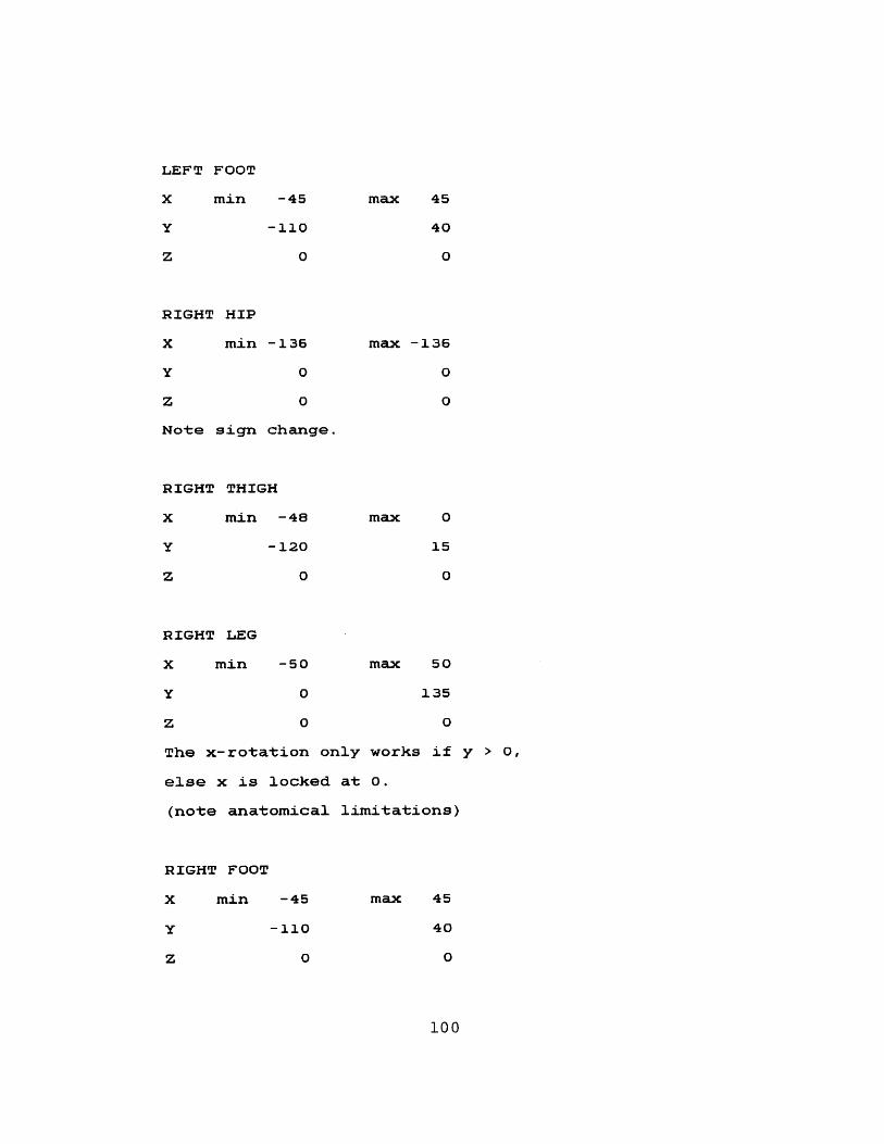
LEFT FOOT
X min
Y
z
-45
-110
0
RIGHT HIP
X min -136
Y 0
Z 0
Note sign change.
RIGHT THIGH
X min -48
Y -120
z 0
max 45
40
0
max -136
0
0
max 0
15
0
RIGHT LEG
X min -50 max 50
Y 0 135
z 0 0
The x-rotation only works if y > 0,
else x is locked at 0.
(note anatomical limitations)
RIGHT FOOT
X min -45
-110Y
z 0
max 45
40
0
100

SPINE (lumbar region)
X min -20 max 20
Y -85 30
Z -38 36
SPINE (thoracic region)
X min -20 max 20
Y -85 30
Z -38 38
These ranges for both spinal areas
are approximate combined ranges-
LEFT CLAVICLE
X min 20 max 80
y 0 0
z 0 0
LEFT ARM
X min -120 max 50
Y -160 50
z 0 0
Not accounting for twist of humerus
about z-axis
LEFT FOREARM
X min 0 max 0
Y -145 0
Z -70 85
101
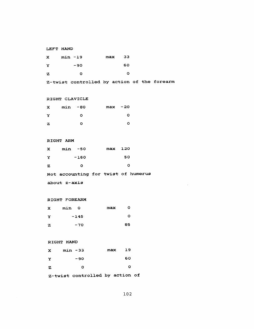
LEFT HAND
X min -19
Y -90
max 33
60
Z 0 0
Z-twist controlled by action of the forearm
RIGHT CLAVICLE
X min -60
Y 0
z 0
max - 20
0
0
RIGHT ARM
X min -50 max 120
Y -160 50
z 0 0
Not accounting for twist of humerus
about z-axis
RIGHT FOREARM
x min 0
Y -145
z -70
RIGHT HAND
X min -33
-90Y
z
Z-twist controlled b
0
max 0
0
85
max 19
60
0
y action of
102
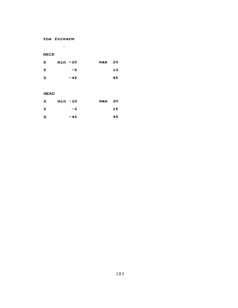
the forearm
min -20
-5
max 20
10
-45
X min -20
-5
-45
45
max 20
15
45
103
NECK
x
y
z
HEAD
y
z
REFERENCES
Il) Badler, Norman, Conversation, 1983.
[2] Badler, N., "Design of a Human Representation
Incorporating Dynamics and Task Simulation",
Siggraph'82 Tutorial, July 1982.
[3] Badler, N. I., O'Rourke, Joseph, "Representation
of Articulable, Quasi-Rigid, Three-Dimensional
Objects", Proceedings, Workshop on
Three-Dimensional object Representation,
University of Pennsylvania, April 1979, pp. B1-B24.
[4] Badler, N., O'Rourke, J., and Kaufman, B.,
"Special Problems in Human Movement Simulation",
Computer Graphics, Vol. 14, No. 3, 1980, pp.
189-197.
[5] Badler, N., and Smoliar, S., "Digital
Representations of Human Movement", Computing
Surveys, Vol. 11, No. 1, March 1979, pp. 19-38.
[6] Bolt, R. A., Funding proposal for the development
of a Graphical Marionette, Architecture Machine
Group, MIT, 1981.
[7] Bolt, R. A., "'Put-That-There': voice and gesture
at the graphics interface", Proc. Siggraph, Vol.
14, pp. 262-270.
[8] Brennan, S., Caricature Generator, Master's Thesis,
Architecture Machine Group, MIT, 1982.
[9) Callahan, Mark, Three Dimensional Display Headset
for Personalized Computing, Master's Thesis,
Architecture Machine Group, MIT, 1983.
[10) Calvert, T.W., Chapman, J., and Patla, A., "The
Integration of Subjective and Objective Data in
the Animation of Human Movement", Computer
104
Graphics, Vol. 14, No. 3, 1980, pp. 198-203.
[11] Calvert, T.W., and Chapman, J., "Aspects of the
Kinematic Simulation of Human Movement", Computer
Graphics and Applications, Vol. 2, No. 9,
November 1982.
[12] Conati, F.C., Real-Time Measurement of Three-
Dimensional Multiple Rigid Body Motion,
Master's Thesis, MIT, 1977.
[13] Cutting, James E., "A Program to Generate
Synthetic Walkers as Dynamic Point-Light
Displays", Behavior Research Methods and
Instrumentation Vol.10, No.1, 1978.
[14] Dooley, Marianne, "Anthropometric Modeling
Programs - A Survey," IEEE Computer Graphics and
Applications, Vol. 2, No. 9, November, 1982.
[15] Diffrient, Niels, Tilley, Alvin R., and Bardagjy,
Joan C.,Humanscale 1/2/3, Henry Dreyfuss
Associates, MIT Press, Cambridge, Ma., 1974.
[16] Gage, S., ed. Optoelectronics Applications Manual,
Hewlett-Packard Company, McGraw-Hill, N.Y., 1981.
[17] Ginsberg, Carol, unpublished Master's Thesis,
Dept. of Computer Science and Electrical
Engineering, MIT, 1983.
[18] Hoffman, D.D., and Flinchbaugh, B.E.,
"The Interpretation of Biological Motion", A.I.
Memo No. 608, Artificial Intelligence Laboratory,
MIT, December, 1980.
[19] Hutchinson, A., Labanotation, Theatre Arts Books,
N.Y., 1970.
[20] Kelley, David L., Kinesiology Fundamentals of
Motion Description, Prentice-Hall, Englewood
Cliffs, N.J., 1971.
105
[21] Knuth, Donald E., The Art of Computer Programming:
Fundamental Algorithms, Addison-Wesley, Reading,
Ma., 1968.
[22] Mann, R.W., Rowell, D., Dalrymple, F.C.,
Conati, F.C., Tetewsky, A., Ottenheimer, D.,
and Antonsson, E., "Precise, rapid, automatic 3-D
position and orientation tracking of multiple
moving bodies", Memo of the Dept. of
Mechanical Engineering, MIT, 1981.
[23] Miller, Lynn, Bachelor's Thesis, Dept. of Computer
Science and Electrical Engineering, MIT, 1982.
[24] Negroponte, Nicholas, "Media Room", Proceedings
of the SID, Vol. 22/2, 1981.
[25] Newman, William M., and Sproull, Robert F.,
Principles of Interactive Computer Graphics,
McGraw-Hill, New York, 1979.
[26] Nisselson, Jane, A Model Kit: a system for
constructing three-dimensional interactive
graphic models, Master's Thesis, Architecture
Machine Group, MIT, 1983.
[27] O'Donnell, T.J., and Olsen, A.J., "GRAMPS
- A Graphics Language Interpreter for Real-Time,
Interactive, Three-Dimensional Picture Editing
and Animation", Computer Graphics, Vol. 15,
No. 3, August 1981, pp. 133-142.
[28] Parke, Frederic I., "Parameterized Models for
Facial Animation", Computer Graphics and
Applications, Vol. 2, No. 9, November 1982.
[29] Plagenhoef, Stanley, Patterns of Human Motion A
Cinematographic Analysis, Prentice-Hall, Englewood
Cliffs, N.J., 1971.
[30] Reichardt, Jasia, Robots: Fact, Fiction, and
106
Prediction, Penguin, 1978.
[31] Rashid, R.F., Lights: A System for the
Interpretation of Moving Light Displays, Ph.D.
Thesis, University of Rochester, 1980.
[32] Richter, Jean Paul, The Literary Works of Leonardo
da Vinci, Vol. 1, University of California Press,
1977.
[33] Rogers, David F., and Adams, J. Alan, Mathematical
Elements for Computer Graphics, McGraw-Hill,
New York, 1979.
[34] Tremblay, J.P., and Sorensson, P.G., An
Introduction to Data Structures with Applications,
McGraw-Hill, New York, 1976.
[35] Ullman, S., "The Interpretation of Structure from
Motion", A.I. Memo 476, Artificial Intelligence
Laboratory, MIT, October, 1976.
[36] Webb, Jon A., and Aggarwal, J.K., "Structure from
Motion of Rigid and Jointed Objects", Artificial
Intelligence, Vol. 19, No. 1, September, 1982,
pp. 107-130.
[37] Wittkower, Rudolf, Idea and Image Studies in the
Italian Renaissance, Thames and Hudson, Great
Britain, 1978.
[38] Zeltzer, D., "3D Movement Simulation", Siggraph
'82 Tutorial, July 1982.
[39] Zeltzer, D., "Motor Control Techniques for Figure
Animation", Siggraph '82 Tutorial, July 1982.
[40] Zeltzer, D., "Motion Planning Task Manager for a
Skeleton Animation System", Siggraph '82 Tutorial,
July 1982.
[41] Zeltzer, D., "Representation of Complex Animated
107
Figures", Proceedings, Graphics Interface '62,
May 1982.
108
ACKNOWLEDGMENTS
My first words of acknowledgment go to the Architecture
Machine Group community as a whole - there are many
fine people here. Their help and support was
invaluable over the past year.
In particular, gracias to Eric Brown for always
offering help and advice.
Thanks to Andrew Lippman for introducing me to this
project in the first place, and to Ken Sloan for his
support and encouragement and deadlines. More thanks
to Patrick Purcell for his continuing interest in the
aesthetic aspects of the work.
A word of recognition must also be extended to Mayumi
Yoshinari of NHK, whose ideas led to the inception of
the "Graphical Marionette".
And, of course, to my "other half" in this project,
Carol Ginsberg, I offer my appreciation for all the
collaborative work we have accomplished.
109