Embed Size (px)
Citation preview

1
August 2005
2000 SERIES
CABLE REPAIR PROCEDURE 2100 Series, 2000 Series & Eventer
EVENTER
2100 SERIES
7514 Alabonson Rd. Houston, Texas 77088 281-999-6900 281-999-6966 (fax)
51A Caldari Rd., #16 Concord, Ontario L4K 4G3 905-760-7539 905-775-4275 (fax)
Nova House Audley Avenue Enterprise Park Newport, Shropshire, UK TF10 7DW 011-44-1952-815730
2
1. Lower the carriage to engage the
mast latch system. (Figure 1.)
2. Remove the large gear cover from winch. (Figure 2.)
3. Cut the old cable assembly two inches below the looped end of cable using cable cutters or a cutting torch. (Figure 3.)
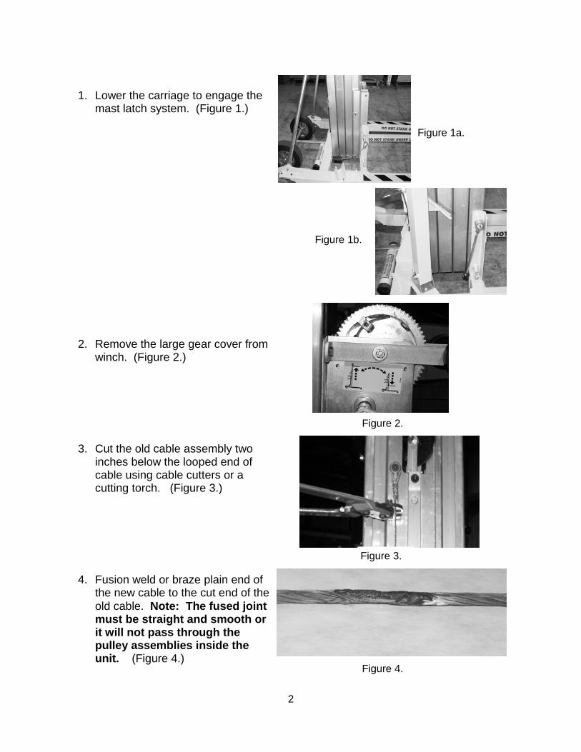
4. Fusion weld or braze plain end of the new cable to the cut end of the old cable. Note: The fused joint must be straight and smooth or it will not pass through the pulley assemblies inside the unit. (Figure 4.)
Figure 1a.
Figure 1b.
Figure 4.
Figure 3.
Figure 2.
3
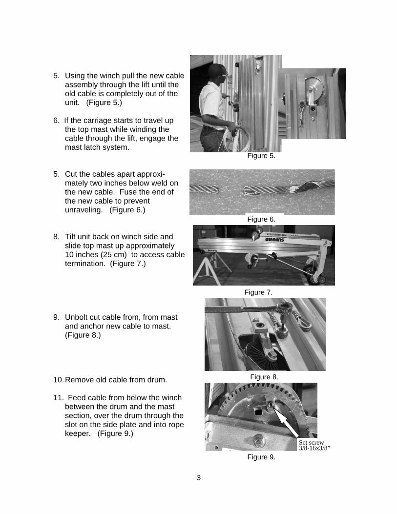
5. Using the winch pull the new cable
assembly through the lift until the old cable is completely out of the unit. (Figure 5.)
6. If the carriage starts to travel up
the top mast while winding the cable through the lift, engage the mast latch system.
5. Cut the cables apart approxi-mately two inches below weld on the new cable. Fuse the end of the new cable to prevent unraveling. (Figure 6.)
8. Tilt unit back on winch side and
slide top mast up approximately 10 inches (25 cm) to access cable termination. (Figure 7.)
9. Unbolt cut cable from, from mast and anchor new cable to mast. (Figure 8.)
10.Remove old cable from drum.
11. Feed cable from below the winch between the drum and the mast section, over the drum through the slot on the side plate and into rope keeper. (Figure 9.)
Set screw 3/8-16x3/8”
Figure 5.
Figure 6.
Figure 7.
Figure 8.
Figure 9.
4
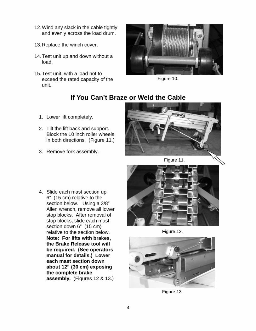
12.Wind any slack in the cable tightly
and evenly across the load drum.
13.Replace the winch cover.
14.Test unit up and down without a load.
15.Test unit, with a load not to exceed the rated capacity of the unit.
Figure 10.
1. Lower lift completely.
2. Tilt the lift back and support. Block the 10 inch roller wheels in both directions. (Figure 11.)
3. Remove fork assembly.
4. Slide each mast section up 6” (15 cm) relative to the section below. Using a 3/8” Allen wrench, remove all lower stop blocks. After removal of stop blocks, slide each mast section down 6” (15 cm) relative to the section below. Note: For lifts with brakes, the Brake Release tool will be required. (See operators manual for details.) Lower each mast section down about 12” (30 cm) exposing the complete brake assembly. (Figures 12 & 13.)
Figure 11.
Figure 12.
Figure 13.
If You Can’t Braze or Weld the Cable
5
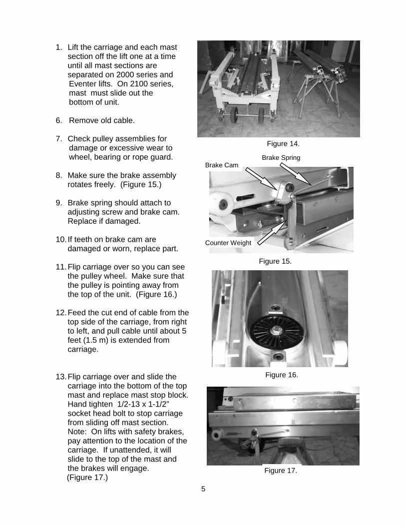
1. Lift the carriage and each mast section off the lift one at a time until all mast sections are separated on 2000 series and
Eventer lifts. On 2100 series, mast must slide out the bottom of unit. 6. Remove old cable. 7. Check pulley assemblies for damage or excessive wear to wheel, bearing or rope guard. 8. Make sure the brake assembly
rotates freely. (Figure 15.)
9. Brake spring should attach to adjusting screw and brake cam. Replace if damaged.
10. If teeth on brake cam are damaged or worn, replace part.
11.Flip carriage over so you can see
the pulley wheel. Make sure that the pulley is pointing away from the top of the unit. (Figure 16.)
12.Feed the cut end of cable from the top side of the carriage, from right to left, and pull cable until about 5 feet (1.5 m) is extended from carriage.
13.Flip carriage over and slide the
carriage into the bottom of the top mast and replace mast stop block. Hand tighten 1/2-13 x 1-1/2” socket head bolt to stop carriage from sliding off mast section. Note: On lifts with safety brakes, pay attention to the location of the carriage. If unattended, it will slide to the top of the mast and the brakes will engage.
(Figure 17.)
Figure 14.
Figure 15.
Figure 17.
Figure 16.
Brake Cam Brake Spring
Counter Weight
6
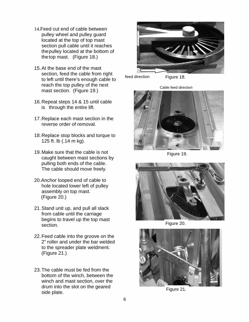
14.Feed cut end of cable between pulley wheel and pulley guard located at the top of top mast section pull cable until it reaches the pulley located at the bottom of the top mast. (Figure 18.) 15.At the base end of the mast
section, feed the cable from right to left until there’s enough cable to reach the top pulley of the next mast section. (Figure 19.)
16. Repeat steps 14 & 15 until cable is through the entire lift.
17. Replace each mast section in the reverse order of removal. 18. Replace stop blocks and torque to 125 ft. lb (.14 m kg). 19. Make sure that the cable is not caught between mast sections by pulling both ends of the cable. The cable should move freely. 20. Anchor looped end of cable to
hole located lower left of pulley assembly on top mast. (Figure 20.)
21. Stand unit up, and pull all slack from cable until the carriage begins to travel up the top mast section. 22. Feed cable into the groove on the 2” roller and under the bar welded to the spreader plate weldment. (Figure 21.) 23. The cable must be fed from the bottom of the winch, between the winch and mast section, over the drum into the slot on the geared side plate.
Figure 18. feed direction
Figure 20.
Figure 21.
Figure 19.
Cable feed direction
7
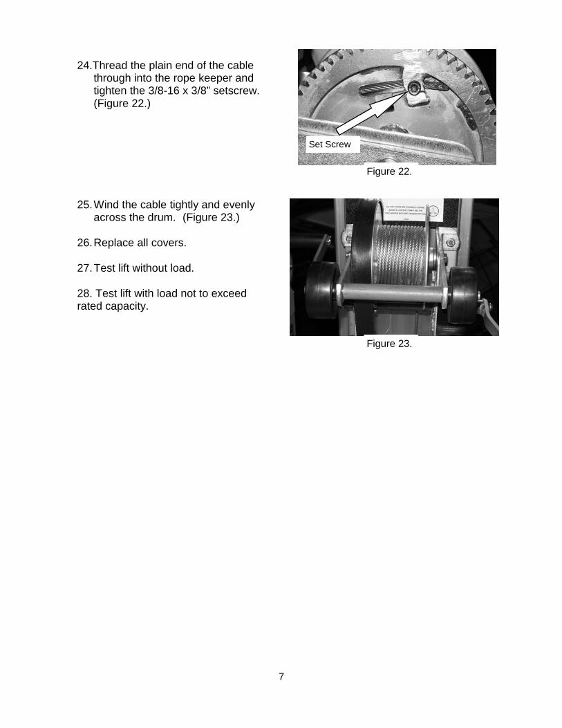
24.Thread the plain end of the cable through into the rope keeper and tighten the 3/8-16 x 3/8” setscrew. (Figure 22.)
25.Wind the cable tightly and evenly
across the drum. (Figure 23.)
26.Replace all covers.
27.Test lift without load. 28. Test lift with load not to exceed rated capacity.
Figure 22.
Set Screw
Figure 23.