Embed Size (px)
Citation preview
AUML2WS-BPEL: A Tool for Engineering andImplementing Agents that Publish Web Services?
Giovanni Casella1,2 and Viviana Mascardi2
1DMI, Universita di Salerno, Via Ponte don Melillo, 84084, Fisciano (SA), [email protected]
2DISI, Universita di Genova, Via Dodecaneso 35, 16146, Genova, [email protected]
Abstract. The Web Services (WS) technology is currently gaining a wider andwider consensus. The features that characterise WSs, namely heterogeneity, dis-tribution, openness, highly dynamic interactions, are some among the key char-acteristics of intelligent agents and MASs.In this paper, we suggest that agents may provide both the coordination frame-work and the engineering metaphor to be exploited for realising complex appli-cations lying on the WSs infrastructure. Based on our claim, we propose to useAUML to model agent interaction protocols, and standard languages for orches-trating WSs to publish the specification of these protocols on the Web.To demonstrate the feasibility of our approach, we have designed and imple-mented a tool that automatically creates WS-BPEL and WSDL specifications cor-responding to AUML interaction protocols. Moreover our tool outputs a Prolog-based representation of the protocol, that our publisher agent is able to use forgenerating its own protocol-compliant code, and a representation in M. Winikoffstextual notation for AUML, whose automatic generation from visual diagramswas not yet supported. Finally, reader agents that interact with the publisher fol-lowing the protocol expressed by the WS-BPEL and WSDL specification havebeen implemented, and a prototype of the “publisher-reader MAS” has been builtand tested using the JADE platform.
Keywords. Intelligent Agents, Web Services, AUML, WSDL, WS-BPEL, Agent-Oriented Software Engineering
1 Introduction and Motivation
Thanks to its applicability to many heterogeneous domains, the Web Services (WS)technology is gaining a wider and wider consensus. According to the W3C [20], “a WSis a software system designed to support inter operable machine-to-machine interactionover a network. It has an interface described in a machine-processable format (specif-ically WSDL). Other systems interact with the Web service in a manner prescribed byits description using SOAP-messages, typically conveyed using HTTP with an XML se-rialisation in conjunction with other Web-related standards.”
? Partially supported by the project “Specifica e verifica di protocolli di interazione fra agenti”funded by the “Progetti di Ricerca di Interesse Nazionale, Bando MIUR 2005”.

Software applications written in various programming languages and running onvarious platforms can both expose themselves as WSs, and use other WSs. Thus, WSsare heterogeneous in their nature. Also, they are designed to allow machine-to-machineinteraction. This interaction takes place over a network, such as the Internet, thus WSsare by definition distributed, and operate in an open and highly dynamic environment.
Heterogeneity, distribution, openness, highly dynamic interactions, are some amongthe key characteristics of intelligent agents and MASs. The AgentLink III Agent Tech-nology Roadmap [23] proposes the following definition: “an agent is a computer sys-tem that is capable of flexible autonomous action in dynamic, unpredictable, typicallymulti-agent domains. ”
WSs and intelligent software agents share many common features, and this suggeststhat some relationship between the two technologies should exist. Actually, the mostrecent literature in the agents’ field devotes much space to these relationships.
Also limiting ourselves to publications of the last year (2005), we find many consid-erations on the links between agents and WSs. For example, the already cited AgentLinkIII Roadmap puts in evidence that WSs “provide a ready-made infrastructure that is al-most ideal for use in supporting agent interactions in a multi-agent system. More impor-tantly, perhaps, this infrastructure is widely accepted, standardised, and likely to be thedominant base technology over the coming years. Conversely, an agent-oriented view ofweb services is gaining increased traction and exposure, since provider and consumerweb services environments are naturally seen as a form of agent-based system.”
A very nice representation of the key agent techniques, and their approximate WSequivalents, has been given by C. Walton in [36], where agents have their counterpartin WSs, agent communication is related to SOAP and WSDL, and agent ontologies arerelated to RDF-S and OWL. In that paper, Walton proposes to decompose agents intoa stub, that executes agent interaction protocols and is responsible for communicationbetween agents, and a body, which encapsulates the reasoning processes, and is encodedas a set of decision procedures. Both the stub and the body should be implemented asWSs.
In [9], P. A. Buhler and J. M. Vidal summarise the relationship between agentsand WSs with the aphorism “Adaptive Workflow Engines = Web Services + Agents”:namely, WSs provide the computational resources and agents provide the coordinationframework. They propose the use of the BPEL4WS1 language as a specification lan-guage for expressing the initial social order of the multi-agent system.
The CooWS architecture defined by L. Bozzo, V. Mascardi, D. Ancona and P.Busetta [6] exploits BPEL4WS for representing the behavioural knowledge of agentsmodelled according to the BDI architecture [30] and able to cooperatively exchangeplans (“CooBDI” agents). The advantage of representing plans as specifications of WSsis that atomic actions in plans’ bodies are just invocations of WSs, and thus can be eas-ily shared by all the agents. This makes exchange of plans profitable for all the agentsin the system.
The view of the cited researchers is that agents and WSs are complementary tools:WSs provide the infrastructure, and agents provide the coordination framework.
1 BPEL4WS is previous name of the business process language for WSs that is currently named“WS-BPEL”.

However, WSs are not always seen as mere infrastructure providers: referring toWS choreography languages, M. Baldoni, C. Baroglio, A. Martelli, V. Patti, and C.Schifanella [4] write that “choreographies and agent interaction protocols undoubtedlyshare a common purpose. In fact, they both aim at expressing global interaction pro-tocols, i.e. rules that define the global behaviour of a system of cooperating parties.”Thus, WS and agent technologies share some commonalities also in their goal of pro-viding tools, languages, and methods necessary for engineering systems that behave ina correct way, for example w.r.t. a given interaction protocol.
Our position integrates both points of view. We think that, besides the coordinationframework, agents also provide the metaphor that can be exploited for engineering andcorrectly implementing MASs based on the WSs infrastructure. Based on this claim, wepropose to use AUML to model agent interaction protocols and WS-BPEL and WSDLto publish the specification of these protocols on the Web. To demonstrate the feasibilityof our approach, we have designed and implemented a tool that takes in input an AUMLinteraction protocol diagram and gives in output the specification of the protocol in WS-BPEL and WSDL.
To the best of our knowledge, there is only one previous attempt to exploit UML forengineering WSs. In [24], K. Mantell describes a tool which takes processes defined inUML and generates the corresponding BPEL4WS and WSDL files to implement thatprocess. The only UML diagram that could be translated into BPEL4WS (according tothe paper; no further check is possible since the tool is no longer available) is the activ-ity diagram. The proposed approach enables service-oriented BPEL4WS componentsto be incorporated into an overall system design utilising existing software engineeringpractices. Additionally, the mapping from UML to BPEL4WS permits a model-drivendevelopment approach in which BPEL4WS executable processes can be automaticallygenerated from UML models. Our approach is complementary to K. Mantell’s one: wetranslate interaction protocols represented as AUML protocol diagrams into WS-BPELabstract processes, and he translates UML activity diagrams into executable BPEL4WSprocesses. Besides this, Mantell’s contribution is mainly concerned with the engineer-ing stage, while our contribution also applies to the deployment stage: this is the featurethat, more than others, makes our work original.
Besides the WSDL and WS-BPEL documents, our tool outputs a Prolog-based rep-resentation of the protocol, that the publisher agent uses for automatically generatingits own protocol-compliant code, and a representation in M. Winikoff’s textual notationfor AUML [37]. By making WS publishing easier, faster and less error-prone (sincehighly automatised), we support collaboration among agents that need to communicatewith other agents whose features are initially unknown. The scenario that we addressis inspired by the already cited “provider and consumer web services which are natu-rally seen as a form of agent-based system”. We complement this point of view sincewe have provider and consumer agents, and the good that is provided/consumed is aservice. By reading the WS-BPEL document published by the provider, the consumercan learn the communication protocol to follow in order to obtain the service, analyseit, and decide if and when it is appropriate to engage in a dialog with the provider [3].The generation of executable code from an AUML specification, very useful to makeour AUML2WS-BPEL self-contained, and performed by the publisher agent by ex-

ploiting meta-programming techniques, has been dealt with by some papers and imple-mented toolkits, such as [21, 18, 31, 11]. Instead, no toolkit for producing a documentin Winikoff’s textual notation for AUML starting from a visual diagram, existed: itsimplementation represents an original contribution of our work.
The paper is organised in the following way: Sections 2 and 3 introduce AUML andthe technologies behind WSs, respectively. Section 4 introduces the AUML2WS-BPELtool. Section 5 discusses our approach to the translation of AUML interaction proto-cols both into Winikoff’s formalism and into ad-hoc XML- and Prolog-based notations,whereas Section 6 illustrates how we obtain the WS-BPEL and WSDL documents fromthe XML-based notation. Section 7 describes how the producer (or “publisher”) “im-plements itself” driven by the Prolog-based version of the AUML interaction protocol,and how it engages in dialog with the consumer (“reader”) inside the JADE platform.Section 8 concludes.
2 Agent Interaction Protocols in AUML
Agent-Oriented Software Engineering (AOSE) studies how existing techniques can beadapted or extended in order to engineer MASs. Currently, many AOSE methodologies(for example, Gaia [38]), notations (such as AUML) and projects (the “Flexible andRobust Protocol-Based Interaction between Agents in Open Systems2” and “SocietiesOf ComputeeS (SOCS)3”, just to cite two recent ones) take Agent Interaction Protocols(AIPs) as their starting point. We consider the AUML interaction diagrams specificationproposed by the FIPA Technical Modeling Committee [15] as our reference notation forAIPs.
An AIP is usually defined in relation to a particular agent activity. AIPs in AUMLextend UML 2.0 sequence diagrams [29]. The protocol name is contained in a boxon the upper-left corner of the diagram and is preceded by the keyword sd (sequencediagram). The AIP is characterised by the following features:
– Actors, roles, and lifelines. An AIP consists of some lifelines; for each lifeline, arectangular box contains information about the agent to which that lifeline belongs,the role it plays in the MAS, and its class. The syntax used is agent-name/agent-role: agent-class.
– Message exchange. Labelled arrows between two lifelines represent messages. Mes-sages must satisfy standardised communication languages (e.g. the FIPA agentcommunication language, FIPA-ACL [16], or KQML [26]) which allow to spec-ify the “speech act” (or “performative”) of the message and the fields that it isexpected to have. Since a protocol that has a single, sequential path from the initialstate to the final state is worthless and reduces the autonomy for agents, AUMLallows agents to consider several alternatives during the interaction based on theirinternal state and the state of the interaction. To this aim, it supports different in-teraction operators. A box, with an interaction operator given in its top-left corner,
2 http://www.cs.rmit.edu.au/agents/protocols/3 http://lia.deis.unibo.it/research/socs/
can surround a part of the sequence diagram. Boxes can recursively contain mes-sages and other boxes, and can be divided into a number of regions separated fromeach other by heavy horizontal dashed lines. Each region can include a conditiondepicted as text in square brackets. If the condition is satisfied, then that region isselected and the activities inside it are performed. The interaction operators sup-ported by AUML include weak sequencing, alternative, option, andloop (see [15]).
– Weak sequencing operator. The weak sequencing operator as defined in UML2.0 means a weak sequencing in a sequence of messages, that is to say, the messageswithin this box on the same lifeline are ordered but it is not possible to make anyassumption for message ordering coming from different lifelines in the same box.
– Alternative operator. Alternative means that there are several paths to follow,and that agents have to choose at most one to continue. Guards are associated withalternatives: when a guard is evaluated to true, that alternative path is chosen. Anelse alternative may be optionally present: it is entered if no guard evaluates totrue. If no guard is evaluated to true, and no else alternative is provided, thealternative box of the diagram is not executed.
– Option operator. The option operator only considers one path in the region. If thecondition associated with this path is evaluated to true, then the path is executed,else nothing happens and the interaction follows after this portion of the diagram.
– Loop operator. The loop operator allows designers to represent that an orderedset of activities has to be applied several times. Designers can use either lower andupper bounds or a boolean expression. As long as conditions are satisfied, the loopis executed and the messages are sent and received.
In AUML, parameters are written separately outside the diagram in a comment, stereo-typed as <<parameters>>. AIPs can have many parameters such as content lan-guage for messages, agent communication language (ACL), ontology, etc.
To make an example, Figure 1 shows an AIP modelled using AUML. The diagramis named FruitMarket (upper left label), and describes a scenario where a fruit seller(the agent on the left, named fs, playing the role of fruitSeller and belonging tothe fruitSellerClass) interacts with a fruit buyer (the agent on the right, namedfb, playing the role of fruitBuyer and belonging to the fruitBuyerClass).
The content language is first order logic, and we assume that an ontology namedFruitMarketOntology contains all the information required by the agents to un-derstand the content of the exchanged messages (the <<parameters>> box on thetop of the diagram). Since it is becoming the de facto standard, we adhere to the FIPA-ACL message syntax; as a consequence, the ACL parameter always assumes the “FIPA-ACL” value in our diagrams, and we drop it from the diagram for readability.
The message that fires the protocol is a request from the buyer to the seller aboutthe availability and price of a certain kind of fruit, represented by the logical variableF. Logical variables are identified by uppercase strings, like in Prolog, and are a sort ofplaceholder that will be instantiated during the actual execution of the protocol.
According to the availability of the requested fruit, the seller can
– either perform a sequence of activities (weak sequencing box) that consist infirst informing the buyer that fruit F is available, and then proposing to buy the

Fig. 1. An interaction protocol in AUML

fruit at price EuroForKg. At this point, the seller may expect two reactions from thebuyer (alternative box):• the buyer prefers to decide the delivery and payment mode, rather then getting
a discount. Thus, it sends two requests about the accepted delivery modes andpayment methods, to which the seller answers with two lists of possibilities,and then the buyer either accepts the proposal, choosing one delivery methodand one payment method among the possible ones, or it refuses.
• the buyer prefers to get a discount, also if this means that it will not be ableto choose the delivery and payment methods. Thus, it sends a call for proposal(cfp) to the seller, asking to make another proposal with discounted price, andfixed delivery and payment methods. The seller makes the proposal, and again,the buyer can either accept or refuse it.
– or it can inform the buyer that fruit F is not available, and, optionally (optionbox), inform the buyer that the fruit will be available from a certain date T.
3 Web Services
The goal of WSs is to achieve universal interoperability between applications by usingWeb standards lying on XML.
WS are formally described using WSDL (Web Services Description Language,[12]) while SOAP (Simple Object Access Protocol [27]) and UDDI (Universal De-scription, Discovery, and Integration, [34]) are used to support interaction and com-munication between WSs. Another XML-based language, WS-BPEL [2] (once namedBPEL4WS), provides a formal specification of business processes and business interac-tion protocols extending the original WSs interaction model. Our work is mainly basedon WSDL and WS-BPEL.
WSDL. WSDL defines an XML grammar for describing WSs as distributed softwarecomponents that provide operations by means of exchange of messages. A WS is com-pletely described, at an abstract level, by the following language elements:
– Types: a set of data type definitions.– Message: an abstract, typed definition of the data being exchanged.– Operation: an abstract description of an action, in terms of input and output mes-
sages, supported by the service.– PortType: an abstract collection of operations.
Abstract elements are associated with concrete protocol and data format specifi-cations using reusable bindings described by other language elements (Binding, Port,Service).
WS-BPEL. The Web Services Business Process Execution Language (WS-BPEL) is anotation for specifying business process behaviours (business protocols) based on WSs.Using WS-BPEL it is possible to describe a business process in two ways:
– Executable Processes: describe the actual behaviour of a participant in a businessinteraction and can be executed by an engine.

– Business Protocols: describe the mutually visible message exchange of each of theparties involved in the protocol, without revealing their internal behaviour.
For the purpose of this work, only business protocols are used and described.WS-BPEL is layered on top of several XML specifications: WSDL, XML Schema,
and XPath. Among these, WSDL is the most important for the WS-BPEL language; infact, at the core of the WS-BPEL process model is the notion of peer-to-peer interactionbetween services described in WSDL. A business protocol defines how to coordinatethe interactions between a process instance, modelled as a WSDL service, and its part-ners. All partners and interactions with these partners are described in terms of abstractWSDL interfaces (PortType and Operation).
Each WS involved in the process is defined by a role played by the service, whilevariables and messages properties, which are a type of variable property, representprotocol-relevant data used to describe the process.
In the description of business protocols, the assignment of values to variables canbe transparent or opaque. Opaque assignment is a useful way to describe behaviouralalternatives where the mechanism for choosing the alternative is private. This allowsthe use of nondeterministic data values to make it possible to capture the essence ofpublic behaviour while hiding private aspects. For example an opaque value can be as-signed to a variable to choose conditional branch in the process describing behaviouralalternatives without revealing the actual decision processes performed.
WS-BPEL’s main features are:
– Partner Links. The WS-BPEL partner link type characterises the conversationalrelationship between two services by defining the “roles” played by each service inthe conversation, and specifying the WSDL portType provided by each serviceto receive messages within the context of the conversation. Each partner link ischaracterised by a partnerLinkType, and more than one partner link can becharacterised by the same partnerLinkType. The role of the business processitself is indicated by the attribute myRole and the role of the partner is indicatedby the attribute partnerRole.
– Message exchange. Message exchange can be described and implemented by per-forming the invoke and receive activities that WS-BPEL offers. Invokingan operation on a service provided by a partner, can be either a synchronous re-quest/response operation or an asynchronous one-way operation. An asynchronousinvocation requires only the input message of the operation because it does not ex-pect a response as part of the operation, while a synchronous invocation requiresboth an input message and an output message. In our approach we have only usedasynchronous operations, since they better adapt to the asynchronous nature of in-teractions among agents and to their autonomy in deciding when sending messages.
– Sequence activity. A sequence activity contains one or more activities that are per-formed sequentially, in the order in which they are listed within the sequencetoken.
– Switch activity. The switch activity consists of an ordered list of one or more con-ditional branches defined by case elements, followed optionally by an otherwisebranch. The first branch whose condition holds true (the case branches are consid-

ered in the order in which they appear) is taken and provides the activity performedfor the switch.
– If activity. The if activity consists of an ordered list of one or more conditionalbranches defined by if, elseif elements, followed optionally by an else branch.
– While activity. The while activity supports repeated performance of a specifiediterative activity, performed until the given Boolean while condition no longerholds true.
Conditions are represented by WS-BPEL variables.
4 AUML2WS-BPEL: the big picture
Many of the features that characterise WS-BPEL abstract processes, make them verysuitable to represent AIPs and correspond in a pretty precise way to those that char-acterise AUML (Table 1). Due to this tight correspondence and to the existing rela-tionships between agents and WSs introduced in Section 1, we propose to use AUMLfor representing AIPs, and WS-BPEL and WSDL for publishing them on the Web: ourreference scenario is that where one “service publisher/producer” interacts with one“service reader/consumer”.
AUML WS-BPEL
Roles ag-name/ ag-role: ag-classbox on top of lifelines
myRole and partnerRoletags in Partner Links
Message Labelled arrows between lifelines invoke and receive act.Content Speech-act based UnspecifiedSequence Weak Sequencing op. Sequence act.Condition Alternative op. Switch act.Option Option op. If act.Cycle Loop op. While act.
Table 1. Correspondence between AUML and WS-BPEL concepts
Since there are some well-known advantages of using computational logic for build-ing intelligent agents [32, 25, 35], we implement the agent that publishes the WS intuProlog [14], and we exploit the meta-programming facilities that Prolog offers to al-low the publisher to generate and execute its own protocol-compliant code. Thanks tothe integration of tuProlog into JADE [5] offered by DCaseLP [19], and to the imple-mentation of dummy reader agents built ad-hoc for adhering to the published AIP in acorrect way, we have developed and executed a MAS prototype in JADE.
AUML2WS-BPEL, developed in Java, takes in input the XMI [28] description ofa UML 2.0 sequence diagram (corresponding to an AUML interaction protocol). Sincecurrently no editors for AUML exist, we limited ourselves to consider only those fea-tures that AUML shares with UML 2.0 in order to edit the AUML AIPs with existingtools for UML and to be able to export them in XMI. By exploiting the Extensible
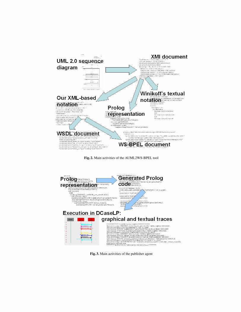
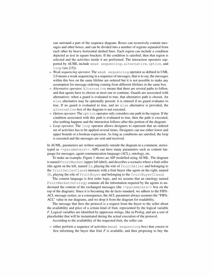
Fig. 2. Main activities of the AUML2WS-BPEL tool
Fig. 3. Main activities of the publisher agent

Stylesheet Language Transformations (XSLT) technology [13], the features of the XMIdocument relevant for generating the AUML textual notation are extracted and threedocuments, one in Winikoff’s textual notation for AUML [37], another in our XML-based notation, and a third in a Prolog-like notation, are generated. The XML-baseddocument is used by another XSLT sheet, to generate both the WSDL and the WS-BPEL documents (Figure 2). The Prolog-based representation of the protocol is usedby the publisher agent to generate the program that complies with the AUML AIP and toexecute it in JADE, by exploiting the tuPInJADE interface implemented by DCaseLP(Figure 3).
We have tested the translator drawing the UML 2.0 sequence diagrams with Posei-don4, and exporting them into XMI, but it should be possible to use any other UMLeditor supporting the 2.0 version. Poseidon allows the diagram designer to label mes-sages with “calls”, and to add documentation strings to them; we represent the mes-sage performatives as calls, and the message content as textual documentation, in or-der to be able to represent content in whatever language. Both calls and documenta-tion are exported into the XMI document, and thus we can extract them during thetranslation process. Our translator, together with the Prolog code that the publisheruses to “implement itself” and with some examples of use, is available from http:
//www.disi.unige.it/person/MascardiV/Software/AUML2WS-BPEL.html.The following sections provide details about the three stages
– AUML visual diagrams→Winikoff’s, XML, Prolog notation;– XML notation→WSDL and WS-BPEL documents;– Prolog notation→ Prolog executable code, and execution into JADE;
respectively.
5 From AUML visual diagrams to textual notations
Visual diagrams have been conceived and designed for human beings, not for machines,thus it is very difficult to reason and work on them for computers.
In order to be processed in an automatic way by computers, textual notations are stillwidely considered to have some significant advantages. For example, M. Winikoff ob-serves that defining the syntax of a textual notation is considerably simpler than definingthe precise syntax of a two-dimensional graphical notation.
For this reason, we chose Winikoff’s textual notation for AUML interaction dia-grams as the main target of our first translation step. Although not used in any succes-sive stage, we produce the document in Winikoff’s notation because, to the best of ourknowledge, no translators from (A)UML visual diagrams into this notation exist. Sincewe took inspiration from Winikoff’s notation for the ad-hoc XML- and Prolog-basednotations used in the successive stages, it was not difficult for us to generate it, and wethought it might be useful for a possible adoption by third parties.
Winikoff defines a textual AUML protocol as a sequence of commands (one perline). The first line defines the name of the protocol (start name) and the last con-cludes the protocol (finish).
4 http://gentleware.com/index.php
Commands in between are used to define:– Agents (agent shortname longname): the shortname is used to refer to theagent when sending messages whereas the longname is used in the box at the top of thelifeline. This avoids having to repeatedly type the long agent name in messages.– Messages between agents (message)– The start and end of boxes (box and end)– The type of the box (weak sequencing, alternative, option, etc)– The boundary between regions within a box (next) and guards (guard)– Continuations (goto and label)– The end of an agent’s participation in the protocol (stop)
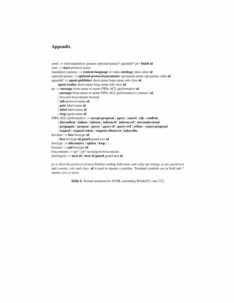
We extend this textual notation with– mandatory parameters (content-language and ontology)– optional parameters (to be eventually defined by the developer)– information on the agent class and role– optional content of the messagesBesides this extension, we assume that in our interaction diagrams there are always twoagents: one that publishes the document that specifies how the interaction should be car-ried on (agent-publisher), and one that reads this document (agent-reader).The message exchange is compliant with FIPA-ACL. The syntax of our extended tex-tual notation for AUML is given in Table 6, and the representation of the protocol shownin Figure 1 using this notation defined is shown in Table 2.
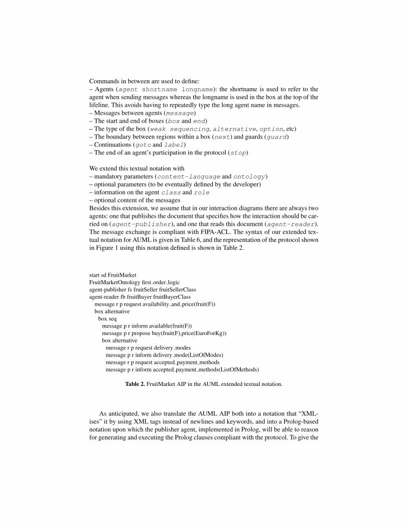
start sd FruitMarketFruitMarketOntology first order logicagent-publisher fs fruitSeller fruitSellerClassagent-reader fb fruitBuyer fruitBuyerClass
message r p request availability and price(fruit(F))box alternative
box seqmessage p r inform available(fruit(F))message p r propose buy(fruit(F),price(EuroForKg))box alternative
message r p request delivery modesmessage p r inform delivery mode(ListOfModes)message r p request accepted payment methodsmessage p r inform accepted payment methods(ListOfMethods)
Table 2. FruitMarket AIP in the AUML extended textual notation.
As anticipated, we also translate the AUML AIP both into a notation that “XML-ises” it by using XML tags instead of newlines and keywords, and into a Prolog-basednotation upon which the publisher agent, implemented in Prolog, will be able to reasonfor generating and executing the Prolog clauses compliant with the protocol. To give the

flavor of the Prolog notation used by the publisher agent to generate its own code, Table7 shows the BNF of the notation, and Table 3 reports a fragment of the FruitMarket AIP.For sake of conciseness, we do not provide details on the XML-based notation, whichis only used by the AUML2WS-BPEL translator as an intermediate format.
process(parameters(
ontology(’FruitMarketOntology’),content language(’first order logic’)),...main fragment(
seq([send(msg(’REQUEST’, ’availability and price(fruit(F))’)),switch([case(no guard,
seq([receive(msg(’INFORM’, ’available(fruit(F),price(EuroForKg))’)),receive(msg(’PROPOSE’, ’buy(fruit(F),price(EuroForKg))’)),switch([case(no guard,
seq([send(msg(’REQUEST’, ’delivery modes’)),...
Table 3. FruitMarket AIP in our Prolog-based notation.
6 From the XML notation to WSDL and WS-BPEL
In this section we describe the translation from AUML protocol diagrams (internallyrepresented in an XML-based notation) into WS-BPEL. We consider AUML diagramsthat describe the interaction between two agents, the publisher that offers a service, thatwe assume to be described by the leftmost lifeline in the AUML diagram, and the readerthat starts the communication requesting a service.
WSDL. The data structures used by the WS-BPEL process are described in a WSDLdocument. The WSDL document begins with standard definitions of name spaces, suchas
xmlns=”http://schemas.xmlsoap.org/wsdl/”xmlns:soap=”http://schemas.xmlsoap.org/wsdl/soap/”
After them, the eight types used in the document are defined:
1. FIPA-ACL performatives. For each performative, an element of type string, whosevalue is fixed to the name of the performative, is defined:
<xs:element name=”agree ca” type=”xs:string” fixed=”agree”/><xs:element name=”cfp ca” type=”xs:string” fixed=”cfp”/>
The definition of FIPA-ACL performatives does not depend on the AUML protocol di-agram under translation: it is always the same for all diagrams.

2. Protocol diagram mandatory parameters. The ontology and content languagenames read from the <<parameters>> field in the AUML diagram, as well as theprotocol name, are defined. From now on, the translation becomes dependent on theinput diagram. In the following, we will refer to Figure 1 as our running example.
<xs:element name=”ontology name” type=”xs:string” fixed=”FruitMarketOntology”/><xs:element name=”content language name” type=”xs:string” fixed=”first-order-logic”/><xs:element name=”protocol name” type=”xs:string” fixed=”sd FruitMarket”/>
3. Information on the reader and on the publisher. The name and role of the agentsthat participate to the protocol are read from the AUML diagram. We recall our assump-tion that the publisher of the document is the leftmost agent in the AUML diagram.
<xs:element name=”publisher name” type=”xs:string” fixed=”fs”/><xs:element name=”publisher role” type=”xs:string” fixed=”fruitSeller”/><xs:element name=”reader name” type=”xs:string” fixed=”fb”/><xs:element name=”reader role” type=”xs:string” fixed=” fruitBuyer”/>
4. Communication links. Using WSDL complex types, the Participant Msg-FromPublisher and the Participant MsgFromReader are defined. They arecharacterised by the sender (publisher, or, resp. reader), the receiver (reader or, resp.publisher) and reply to field, that coincides with the sender.
5. Variables. For each alternative, option and loop operator in the AUMLdiagram, an appropriate WSDL type is defined. In the WS-BPEL document, these typeswill be assigned to variables using opaque assignments that will be instantiated by ei-ther the reader or the publisher, and whose value will determine which one among thepossible execution paths, will be followed. For example, for the first alternative opera-tor, characterised by two alternatives, the following “choose” type is defined:
<xs:element name=”choose type” >
<xs:simpleType><xs:restriction base=”xs:integer”><xs:minInclusive value=”1” /> <xs:maxInclusive value=”2” />
</xs:restriction></xs:simpleType></xs:element>
6. Content of Messages. For each message exchanged, an appropriate message con-tent type is defined. For example, the content of the first message has type:
<xs:element name=”content of Mess 1”type=”xs:string” fixed=”availability and price(fruit(F))”/>
7. Messages. For each message exchanged, a message type is defined. It is charac-terised by the message performative, the communication link (either Participant -MsgFromReader or Participant MsgFromPublisher), the message content(that refers to a content type previously defined), the content language and ontology,as they have been defined in the content language name and ontology nameelements, and the protocol name defined by the protocol name element. For exam-ple, the first message in our running example is:

<message name=”Mess 1”><part name=”performative” element=”request ca”/><part name=”Participant” type=”tns:Participant MsgFromReader”/><part name=”Content” element=”tns:content of Mess 1”/><part name=”Content Language” element=”tns:content language name”/><part name=”Ontology” element=”tns:ontology name”/><part name=”Protocol” element=”tns:protocol name”/>
</message>
8. Port Types. Two port types are defined, one for the publisher (publisherPT)and one for the reader (readerPT). Each port type defines the operation types per-formed by the publisher (resp. the reader), that may be either reception or delivery ofmessages. For each operation the received (sent) messages are also defined. The firsttwo operations declared in the publisher port type, for example, are:
<portType name=”publisherPT”><operation name=”RCV Mess 1”>
<input message=”tns:Mess 1”/></operation>
<operation name=”SND Mess 2”><output message=”tns:Mess 2”/>
</operation>
Partner link types. The WSDL document ends with the definition of the partner linktypes:
<plnk:partnerLinkType name=” fruitSellerfruitBuyerLinkLT”><plnk:role name=” fruitSeller”> <plnk:portType name=”tns:publisherPT”/> </plnk:role><plnk:role name=” fruitBuyer”> <plnk:portType name=”tns:readerPT”/> </plnk:role>
</plnk:partnerLinkType>
WS-BPEL. The WS-BPEL document is based on the WSDL one. After some initialstandard declarations, the WS-BPEL document begins with the partner links defini-tions, that refer to the partner link types in the WSDL document:
<partnerLinks><partnerLink name=”publisherPL”
partnerLinkType=”lns: fruitSellerfruitBuyerLinkLT”myRole=”fruitSeller” partnerRole=”fruitBuyer”/>
<partnerLink name=”readerPL”partnerLinkType=”lns:fruitBuyerfruitSellerLinkLT”myRole=”fruitBuyer ” partnerRole=”fruitSeller”/>
</partnerLinks>
The roles that appear in the partner links are those defined in the rectangular boxeson top of the lifelines, in the AUML diagram.
For each variable type defined in the WSDL, a WS-BPEL variable is declared. Afterthis, the translation of the AUML operators into WS-BPEL activities takes place and

it is driven by the correspondence between AUML operators and WS-BPEL activitiesdepicted in Table 1.
The WS-BPEL document describes the process in terms of invoke and receiveactivities associated to operations that involve delivery and reception of a message.Both the point of view of the publisher and that of the reader are considered, apart forthe first message, sent by the reader to the publisher for starting the interaction, forwhich only the publisher point of view is considered. This is motivated by the state-ment, contained in the specification of the WS-BPEL language, that “A start activity isa receive/pick activity that is annotated with a createInstance=‘‘yes’’attribute.”
Values are associated in a private and opaque way with variables by the partners,depending on the interaction protocol considered. These variables are used in switch,loop, if and option WS-BPEL activities. Each WS-BPEL variable is given theappropriate type among those defined in the WSDL document. For example, a WS-BPEL variable used in an alternative with four choices, is given a type represented byan Integer that ranges in [1,4]. For a loop activity, the corresponding variable is assigneda Boolean type.
Going on with our running example, the first message is translated into:<receive partnerLink=”publisherPL” portType=”lns:publisherPT”
operation=”RCV Mess 1” createIstance=”yes”/>The operation "RCV Mess 1" refers to the reception by the publisher of the messagenamed "Mess 1" (item 8 of the WSDL paragraph). "Mess 1" has a "request ca"performative and content that points to "tns:content of Mess 1" (item 7 of theWSDL paragraph), and finally "content of Mess 1" has a field of type stringwhose value is fixed to "availability and price(fruit(F))" (item 6). Inthe end, this operation represents the reception of the message "request(avai-lability and price(fruit(F))").
In a similar way, the second message (inform("available(fruit(F))")sent by the publisher to the reader) is translated into:
<invoke partnerLink=”publisherPL” portType=”lns:publisherPT”operation=”SND Mess 2”/>
<receive partnerLink=”readerPL” portType=”lns:readerPT”operation=”RCV Mess 2”/>
Note that the translation of the first message only includes the publisher’s point of view,while the translation of the second integrates both perspectives.
The AUML operators that we considered in this paper, are translated in the follow-ing way:
– Weak sequencing. A weak sequencing operator is translated into a sequenceactivity. For example, the only weak sequencing of our example becomes:<sequence>
<invoke partnerLink=”publisherPL” portType=”lns:publisherPT”operation=”SND Mess 2”/>
<receive partnerLink=”readerPL” portType=”lns:readerPT”operation=”RCV Mess 2”/>

<invoke partnerLink=”publisherPL” portType=”lns:publisherPT”operation=”SND Mess 3”/>
<receive partnerLink=”readerPL” portType=”lns:readerPT”operation=”RCV Mess 3”/>
...where Mess 2 refers the message cited above, and Mess 3 refers to propose("buy(fruit(F),price(EuroForKg))") sent by the publisher to the rea-der.
– Alternative operator. The alternative operator is translated into a switchactivity. In our example, the first alternative branch is followed if the publisher hassome fruit to sell to the buyer. In this case, in a hidden/private way, the publisherinstantiates the variable choose1.value 1 with the value 1. Then, the weak se-quencing activity just discussed, takes place:<copy>
<from opaque=”yes”/><to>choose1.value</to>
</copy>
<switch>
<case condition=”choose1.value=1”><sequence>
<invoke partnerLink=”publisherPL” portType=”lns:publisherPT”operation=”SND Mess 2”/>
<receive partnerLink=”readerPL” portType=”lns:readerPT”operation=”RCV Mess 2”/>
....
– Option operator. The Option operator is translated into a WS-BPEL if activity.The only option operator in our example becomes:
<if> <condition condition=”$condition 5.value=true”/><then>
<invoke partnerLink=”publisherPL”portType=”lns:publisherPT” operation=”SND Mess 15”/>
<receive partnerLink=”readerPL”portType=”lns:readerPT” operation=”RCV Mess 15”/>
</then></if>Mess 15 refers to the last message exchanged in our running example, namelyinform("fruit available from(fruit(F),date(T))") sent by thepublisher to the reader.
– Loop operator Finally, the loop operator is translated into a while activity. Al-though our example does not include loops, any translation would look like:<while condition=”$continue 1.value=true”>
<invoke partnerLink=”publisherPL” portType=”lns:publisherPT”operation=”SND Mess 30”/>
<receive partnerLink=”readerPL” portType=”lns:readerPT”

operation=”RCV Mess 30”/>
From the given examples of translation it should be clear that the WS-BPEL doc-ument generated so far contains all the information that was contained in the originalAUML AIP diagram: in this way, the reader can follow the AIP just by reading theWS-BPEL document.
7 The WS publisher: a self-made agent
The publisher of the WSDL and WS-BPEL documents described in Section 6 is im-plemented in tuProlog, and heavily exploits the meta-programming features that Prologoffers for generating and executing its own code, that complies with the Prolog repre-sentation of the protocol.
According to the syntax prescribed by DCaseLP [19] for integrating tuProlog agentsinto JADE, the publisher’s tuProlog program must define a main predicate whosedemonstration is attempted any time JADE activates this agent (characterised by a cyclicbehaviour).
The main predicate defines the publisher’s main activities, namely generating thecode that complies with the AUML AIP (recall that our AUML2WS-BPEL tool alsooutputs a Prolog term representing the AIP: this term is included into the publisher’sknowledge base and is taken as input for this first activity), asserting the code into theknowledge base, and executing it. In our simplified setting, the publisher executes thegenerated code only once, and knows in advance the JADE identifier of the only buyeragent with whom it will interact (fruitBuyer@klimt:1099/JADE).
Before going into the details of the code generation stage, we shortly recall theProlog execution model. The reader can find more information in [33] and [7].
A Prolog program consists of a set of definite Horn clauses looking like Head :-BodyAtom1, ..., BodyAtomN. The easiest way to interpret this clause is that inorder to demonstrate the goal Head, the goals BodyAtom1, ..., BodyAtomN must bedemonstrated, from left to right (“resolution”). The demonstration of a goal defined bya clause with empty body, succeeds. Clauses are attempted in a top-down fashion. If theusage of a clause whose head matches with the goal to demonstrate, does not lead toa successful demonstration, the successive one (whose head matches with the goal, ofcourse) is attempted (“backtracking”). If no clause allows to demonstrate the goal, thegoal’s demonstration fails. It is also useful to recall that in Prolog, a variable (denotedby an uppercase symbol) stands for a single data object, however complex. Once a valueis associated with (“unifies with”) a variable in Prolog, that association (“unification”)is maintained until the demonstration of the goal where the variable appears, ends witha success.
The philosophy behind the generation of a Prolog program starting from the Prologrepresentation of the AIP, is that a finite state machine is simulated by the generatedclauses. States are meaningless terms only used to enforce the correct transitions, andtransitions correspond either to communicative actions (sending or receiving messages),or to check of conditions. In some cases, empty transitions that just move from one
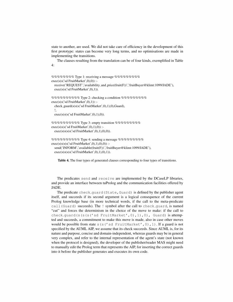
state to another, are used. We did not take care of efficiency in the development of thisfirst prototype: states can become very long terms, and no optimisations are made inimplementing the transitions.
The clauses resulting from the translation can be of four kinds, exemplified in Table4:
%%%%%%%% Type 1: receiving a message %%%%%%%%%exec(s(s(’sd FruitMarket’,0),0)) :-
receive(’REQUEST’,’availability and price(fruit(F))’,’fruitBuyer@klimt:1099/JADE’),exec(s(s(’sd FruitMarket’,0),1)).
%%%%%%%%%% Type 2: checking a condition %%%%%%%%%exec(s(s(’sd FruitMarket’,0),1)) :-
check guard(s(s(s(’sd FruitMarket’,0),1),0),Guard),!,exec(s(s(s(’sd FruitMarket’,0),1),0)).
%%%%%%%%%% Type 3: empty transition %%%%%%%%%exec(s(s(s(’sd FruitMarket’,0),1),0)) :-
exec(s(s(s(s(’sd FruitMarket’,0),1),0),0)).
%%%%%%%%%% Type 4: sending a message %%%%%%%%%exec(s(s(s(s(’sd FruitMarket’,0),1),0),0)) :-
send(’INFORM’,’available(fruit(F))’,’fruitBuyer@klimt:1099/JADE’),exec(s(s(s(s(’sd FruitMarket’,0),1),0),1)).
Table 4. The four types of generated clauses corresponding to four types of transitions.
The predicates send and receive are implemented by the DCaseLP libraries,and provide an interface between tuProlog and the communication facilities offered byJADE.
The predicate check guard(State,Guard) is defined by the publisher agentitself, and succeeds if its second argument is a logical consequence of the currentProlog knowledge base (in more technical words, if the call to the meta-predicatecall(Guard) succeeds). The ! symbol after the call to check guard, is named“cut” and forces the determinism in the choice of the move to make: if the call tocheck guard(s(s(s(’sd FruitMarket’,0),1),0), Guard) is attemp-ted and succeeds, a commitment to make this move is made, also in case other moveswould be possible from state s(s(’sd FruitMarket’,0),1). If a guard is notspecified by the AUML AIP, we assume that its check succeeds. Since AUML is, for itsnature and purpose, concise and domain-independent, whereas guards may be in generalvery complex, and refer to the internal representation of the agent’s state (not knownwhen the protocol is designed), the developer of the publisher/reader MAS might needto manually edit the Prolog term that represents the AIP, for inserting the correct guardsinto it before the publisher generates and executes its own code.
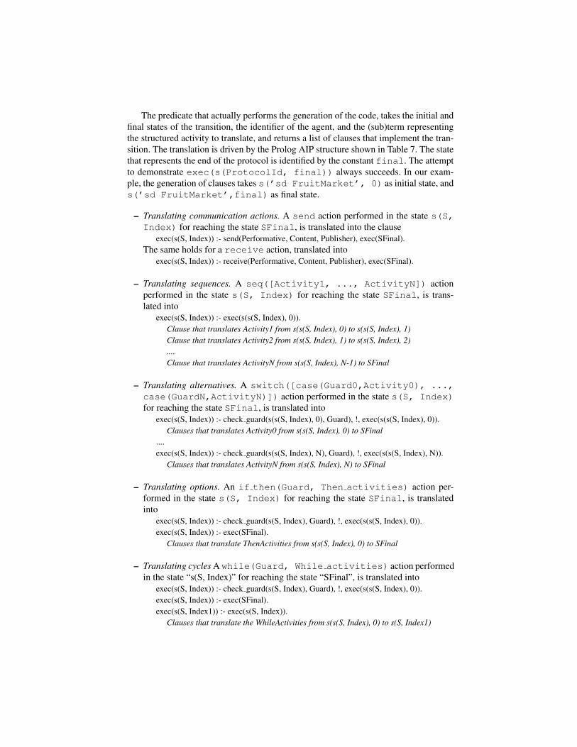
The predicate that actually performs the generation of the code, takes the initial andfinal states of the transition, the identifier of the agent, and the (sub)term representingthe structured activity to translate, and returns a list of clauses that implement the tran-sition. The translation is driven by the Prolog AIP structure shown in Table 7. The statethat represents the end of the protocol is identified by the constant final. The attemptto demonstrate exec(s(ProtocolId, final)) always succeeds. In our exam-ple, the generation of clauses takes s(’sd FruitMarket’, 0) as initial state, ands(’sd FruitMarket’,final) as final state.
– Translating communication actions. A send action performed in the state s(S,Index) for reaching the state SFinal, is translated into the clause
exec(s(S, Index)) :- send(Performative, Content, Publisher), exec(SFinal).The same holds for a receive action, translated into
exec(s(S, Index)) :- receive(Performative, Content, Publisher), exec(SFinal).
– Translating sequences. A seq([Activity1, ..., ActivityN]) actionperformed in the state s(S, Index) for reaching the state SFinal, is trans-lated into
exec(s(S, Index)) :- exec(s(s(S, Index), 0)).Clause that translates Activity1 from s(s(S, Index), 0) to s(s(S, Index), 1)Clause that translates Activity2 from s(s(S, Index), 1) to s(s(S, Index), 2)....Clause that translates ActivityN from s(s(S, Index), N-1) to SFinal
– Translating alternatives. A switch([case(Guard0,Activity0), ...,case(GuardN,ActivityN)]) action performed in the state s(S, Index)for reaching the state SFinal, is translated into
exec(s(S, Index)) :- check guard(s(s(S, Index), 0), Guard), !, exec(s(s(S, Index), 0)).Clauses that translates Activity0 from s(s(S, Index), 0) to SFinal
....exec(s(S, Index)) :- check guard(s(s(S, Index), N), Guard), !, exec(s(s(S, Index), N)).
Clauses that translates ActivityN from s(s(S, Index), N) to SFinal
– Translating options. An if then(Guard, Then activities) action per-formed in the state s(S, Index) for reaching the state SFinal, is translatedinto
exec(s(S, Index)) :- check guard(s(S, Index), Guard), !, exec(s(s(S, Index), 0)).exec(s(S, Index)) :- exec(SFinal).
Clauses that translate ThenActivities from s(s(S, Index), 0) to SFinal
– Translating cycles A while(Guard, While activities) action performedin the state “s(S, Index)” for reaching the state “SFinal”, is translated into
exec(s(S, Index)) :- check guard(s(S, Index), Guard), !, exec(s(s(S, Index), 0)).exec(s(S, Index)) :- exec(SFinal).exec(s(S, Index1)) :- exec(s(S, Index)).
Clauses that translate the WhileActivities from s(s(S, Index), 0) to s(S, Index1)

Once the translation has been completed, the publisher asserts the generated clausesinto its knowledge base, then it starts the execution of the protocol by calling the pred-icate exec(s(ProtocolId, 0)), where ProtocolId stands for the protocolname previously extracted from the AIP (’sd FruitMarket’ in our example). Alog file is produced while the agent executes; it explains how the translation from theProlog notation for AIPs into code is performed, lists the obtained clauses, and tracestheir actual execution.
In order to check the feasibility of our approach, we have implemented reader agentswhose code complies with the AUML AIP diagram (and thus, with the WSDL and WS-BPEL specifications published by the publisher agent). Obviously, where the publisherexpects to receive a message, the reader is expected to send it, and vice-versa. We havelaunched the JADE platform with the Graphical User Interface option and we haveloaded one publisher (seller) and one reader (buyer) into it.
Fig. 4. Message exchange captured by JADE’s sniffer agent
The result of one specific execution run (that where the seller agent has enough fruit,and the buyer agent prefers to choose the delivery and payment methods, rather thangetting a discount: this run corresponds to the case where all the guards are verified, andthe first branches encountered, are taken) is shown graphically in Figure 4, and textuallyin Table 5. The textual trace has been produced by the publisher agent and recorded intoits log file. The seller and the buyer interacted as expected, and the protocol terminatedsuccessfully.
8 Conclusions and Future Work
In this paper we have described the motivations, the design and the implementation ofan AUML to WS-BPEL translator. Although its main purpose and originality is to gen-erate the WSDL and WS-BPEL specifications corresponding to a given AUML AIP,
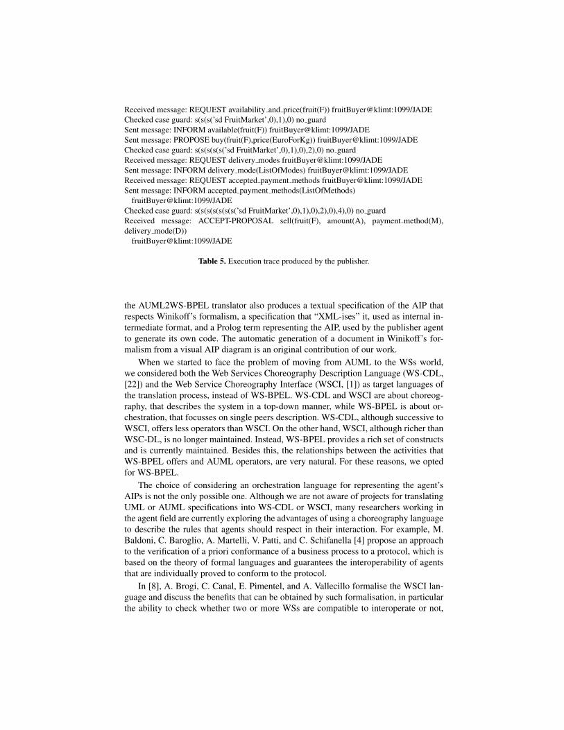
Received message: REQUEST availability and price(fruit(F)) fruitBuyer@klimt:1099/JADEChecked case guard: s(s(s(’sd FruitMarket’,0),1),0) no guardSent message: INFORM available(fruit(F)) fruitBuyer@klimt:1099/JADESent message: PROPOSE buy(fruit(F),price(EuroForKg)) fruitBuyer@klimt:1099/JADEChecked case guard: s(s(s(s(s(’sd FruitMarket’,0),1),0),2),0) no guardReceived message: REQUEST delivery modes fruitBuyer@klimt:1099/JADESent message: INFORM delivery mode(ListOfModes) fruitBuyer@klimt:1099/JADEReceived message: REQUEST accepted payment methods fruitBuyer@klimt:1099/JADESent message: INFORM accepted payment methods(ListOfMethods)
fruitBuyer@klimt:1099/JADEChecked case guard: s(s(s(s(s(s(s(’sd FruitMarket’,0),1),0),2),0),4),0) no guardReceived message: ACCEPT-PROPOSAL sell(fruit(F), amount(A), payment method(M),delivery mode(D))
fruitBuyer@klimt:1099/JADE
Table 5. Execution trace produced by the publisher.
the AUML2WS-BPEL translator also produces a textual specification of the AIP thatrespects Winikoff’s formalism, a specification that “XML-ises” it, used as internal in-termediate format, and a Prolog term representing the AIP, used by the publisher agentto generate its own code. The automatic generation of a document in Winikoff’s for-malism from a visual AIP diagram is an original contribution of our work.
When we started to face the problem of moving from AUML to the WSs world,we considered both the Web Services Choreography Description Language (WS-CDL,[22]) and the Web Service Choreography Interface (WSCI, [1]) as target languages ofthe translation process, instead of WS-BPEL. WS-CDL and WSCI are about choreog-raphy, that describes the system in a top-down manner, while WS-BPEL is about or-chestration, that focusses on single peers description. WS-CDL, although successive toWSCI, offers less operators than WSCI. On the other hand, WSCI, although richer thanWSC-DL, is no longer maintained. Instead, WS-BPEL provides a rich set of constructsand is currently maintained. Besides this, the relationships between the activities thatWS-BPEL offers and AUML operators, are very natural. For these reasons, we optedfor WS-BPEL.
The choice of considering an orchestration language for representing the agent’sAIPs is not the only possible one. Although we are not aware of projects for translatingUML or AUML specifications into WS-CDL or WSCI, many researchers working inthe agent field are currently exploring the advantages of using a choreography languageto describe the rules that agents should respect in their interaction. For example, M.Baldoni, C. Baroglio, A. Martelli, V. Patti, and C. Schifanella [4] propose an approachto the verification of a priori conformance of a business process to a protocol, which isbased on the theory of formal languages and guarantees the interoperability of agentsthat are individually proved to conform to the protocol.
In [8], A. Brogi, C. Canal, E. Pimentel, and A. Vallecillo formalise the WSCI lan-guage and discuss the benefits that can be obtained by such formalisation, in particularthe ability to check whether two or more WSs are compatible to interoperate or not,

and, if not, whether the specification of adaptors that mediate between them can beautomatically generated.
A unifying view of orchestration and choreography is suggested by N. Busi, R.Gorrieri, C. Guidi, R. Lucchi, and G. Zavattaro, that define a notion of conformance be-tween choreography and orchestration which allows to state when an orchestrated sys-tem conforms to a given choreography. Choreography and orchestration are formalisedby using two process algebras and conformance takes the form of a bisimulation-likerelation [10].
Our approach complements these works: we mainly concentrate on engineeringand implementing the publisher in an automatic way, whereas they concentrate on thereader’s side, with the aim of allowing the reader to verify the conformance to thepublished protocol. We plan to implement very shortly a translator from WSDL andWS-BPEL into the Prolog representation of AIPs. In this way, the reader might gen-erate its own code reusing the code generator that we have already implemented forthe publisher, and then it might reason about this generated code following some of thestrategies for conformance verification just illustrated, that often exploit computationallogic.
In the future, we want to improve and extend the AUML2WS-BPEL translator inorder to include it into an integrated environment supporting a complete methodologyfor the design and implementation of MASs. Moreover, we plan to investigate howthe facilities already offered by platforms compliant to the FIPA Abstract Architec-ture Specification [17], including agent-directory services, message-transport-servicesand service-directory-service, can be exploited for publishing and searching WS-BPELdocuments describing AIPs.
Appendix
auml ::= start mandatory-params optional-param* agentdef* pe* finish nlstart ::= start protocol-namemandatory-params ::= content-language cl-value ontology onto-value nloptional-param ::= optional-protocol-parameter opt-param-name opt-param-value nlagentdef ::= agent-publisher short-name long-name role class nl
agent-reader short-name long-name role class nlpe ::= message from-name to-name FIPA-ACL-performative nl
| message from-name to-name FIPA-ACL-performative ( content ) nl| boxstart boxcontents boxend| sub protocol-name nl| goto label-name nl| label label-name nl| stop agent-name nl
FIPA-ACL-performative ::= accept-proposal | agree | cancel | cfp | confirm| disconfirm | failure | inform | inform-if | inform-ref | not-understood| propagate | propose | proxy | query-if | query-ref | refuse | reject-proposal| request | request-when | request-whenever |subscribe
boxstart ::= box boxtype nl| box boxtype nl guard guard-text nl
boxtype ::= alternative | option | loop | ...boxend ::= end boxtype nlboxcontents ::= pe* | pe* nextregion boxcontentsnextregion ::= next nl | next nl guard guard-text nl
pe is short for protocol element Entities ending with name and value are strings, as are guard-textand content, role and class. nl is used to denote a newline. Terminal symbols are in bold and *means zero or more.
Table 6. Textual notation for AUML extending Winikoff’s one [37].

WS-BPELinProlog ::= process(parameters(ontology(String),content language(String)),protocol name(String),agent publisher(short name(String), long name(String)),agent reader(short name(String), long name(String)),main fragment(StructuredActivity))
AtomicActivity ::= send(FIPA ACL Message) | receive(FIPA ACL Message)
StructuredActivity ::= AtomicActivity |while(Guard, StructuredActivity) |switch(CaseActivity) |switch otherwise(CaseActivity, StructuredActivity) |if then(Guard, ThenActivity) |if then else(Guard, StructuredActivity, StructuredActivity) |seq(SequenceActivity)
SequenceActivity ::= [] | [StructuredActivity | SequenceActivity]
CaseActivity ::= [] | [case(Guard, StructuredActivity) | CaseActivity]
FIPA ACL Message ::= msg(FIPA ACL Performative, String)
FIPA ACL Performative ::= ”ACCEPT-PROPOSAL” | ”AGREE” | ”CANCEL” | ”CFP”| ”CONFIRM” | ”DISCONFIRM” | ”FAILURE” | ”INFORM” | ”INFORM-IF”| ”INFORM-REF” | ”NOT-UNDERSTOOD” | ”PROPAGATE” | ”PROPOSE”| ”PROXY” | ”QUERY-IF” | ”QUERY-REF” | ”REFUSE” | ”REJECT-PROPOSAL”| ”REQUEST” | ”REQUEST-WHEN” | ”REQUEST-WHENEVER” | ”SUBSCRIBE”| ”UNKNOWN”
Guard ::= no guard | Atom
Lowercase symbols are terminals, while uppercase are nonterminals. Strings are sequences ofcharacters enclosed in " or ’
Table 7. Prolog notation for AUML.

Bibliography
[1] A. Arkin et al., editor. Web Service Choreography Interface (WSCI) version 1.0.W3C Note 8 August 2002 http://www.w3.org/TR/wsci.
[2] A. Arkin et al., editor. Web Services Business Process Execution Lan-guage (WS-BPEL) Version 2.0, 2005. Oasis Committee Draft 01 September2005, http://www.oasis-open.org/committees/download.php/14616/wsbpel-specification-draft.htm.
[3] M. Baldoni, C. Baroglio, A. Martelli, and V. Patti. Reasoning about interactionprotocols for customizing web service selection and composition. Journal of Logicand Algebraic Programming (JLAP), 2006.
[4] M. Baldoni, C. Baroglio, A. Martelli, V. Patti, and C. Schifanella. Verifying theconformance of web services to global interaction protocols: A first step. In Proc.of EPEW’05 and WS-FM’05, pages 257–271. Springer, 2005.
[5] F. Bellifemine, A. Poggi, and G. Rimassa. Developing multi-agent systems withJADE. In C. Castelfranchi and Y. Lesperance, editors, Intelligent Agents VII, pages89–103. Springer, 2001. LNAI 1986.
[6] L. Bozzo, V. Mascardi, D. Ancona, and P. Busetta. CooWS: Adaptive BDI agentsmeet service-oriented programming. In Proc. of ICWI’05, Volume 2, pages 205–209. IADIS Press, 2005.
[7] I. Bratko. Prolog - Programming for Artificial Intelligence. Addison-Wesley,2000. 3rd ed.
[8] A. Brogi, C. Canal, E. Pimentel, and A. Vallecillo. Formalizing web service chore-ographies. In Proc. of WS-FM’04, 2004. Published also in ENTCS, 105:73-94,2004.
[9] P. A. Buhler and J. M. Vidal. Towards adaptive workflow enactment using multi-agent systems. Information Technology and Management, 6:61–87, 2005.
[10] N. Busi, R. Gorrieri, C. Guidi, R. Lucchi, and G. Zavattaro. Choreography andorchestration: A synergic approach for system design. In Proc. of ICSOC’05,pages 228–240. Springer, 2005.
[11] L. Cabac and D. Moldt. Formal semantics for AUML agent interaction protocoldiagrams. In Proc. of AOSE’04, Revised Selected Papers, pages 47–61. Springer,2005. LNCS 3382.
[12] E. Christensen, F. Curbera, G. Meredith, and S. Weerawarana. Web Services De-scription Language (WSDL) 1.1, 2001. W3C Note 15 March 2001 downloadablefrom http://www.w3.org/TR/wsdl.
[13] J. Clark, editor. XSL Transformations (XSLT) Version 1.0. W3C Recommendation16 November 1999 http://www.w3.org/TR/xslt.
[14] E. Denti, A. Omicini, and A. Ricci. tuProlog: A lightweight prolog for internetapplications and infrastructures. In I. V. Ramakrishnan, editor, Proc. of PADL2001, pages 184–198. Springer, 2001.
[15] M-P. Huget et al. FIPA modeling: Interaction diagrams. First proposal, 2003-07-02. http://www.auml.org/auml/documents/ID-03-07-02.pdf,2003.

[16] Foundation for Intelligent Physical Agents. FIPA ACL message structure spec-ification. Approved for standard, 2002-12-06. http://www.fipa.org/specs/fipa00061/, 2002.
[17] Foundation for Intelligent Physical Agents. FIPA abstract architecture specifica-tion. Approved for standard, 2003-12-03. http://www.fipa.org/specs/fipa00001/, 2003.
[18] J. Gomez-Sanz and J. Pavon. Agent oriented software engineering with IN-GENIAS. In Multi-Agent Systems and Applications III, Proc. of CEEMAS’03.Springer, 2003. LNCS 2691.
[19] I. Gungui, M. Martelli, and V. Mascardi. DCaseLP: a prototyping environmentfor multilingual agent systems. Technical report, Dipartimento di Informatica eScienze dell’Informazione, University of Genova, Italy, 2005. DISI-TR-05-20.
[20] H. Haas and A. Brown. Web Services Glossary – W3C WorkingGroup Note 11 February 2004, 2004. http://www.w3.org/TR/2004/NOTE-ws-gloss-20040211/#defs.
[21] M-P. Huget. Generating code for Agent UML sequence diagrams. Technical re-port, Department of computer science, University of Liverpool, UK, 2002. ULCS-02-020.
[22] N. Kavantzas, D. Burdett, G. Ritzinger, T. Fletcher, Y. Lafon, and C. Barreto,editors. Web Services Choreography Description Language (WS-CDL) Version1.0. W3C Candidate Recommendation 9 November 2005 http://www.w3.org/TR/ws-cdl-10/.
[23] M. Luck, P. McBurney, O. Shehory, S. Willmott, and the AgentLink Community.Agent Technology: Computing as Interaction – A Roadmap for Agent-Based Com-puting. AgentLink III, 2005.
[24] K. Mantell. From UML to BPEL – model driven architecture in a Webservices world, 2005. Downloadable from http://www-128.ibm.com/developerworks/webservices/library/ws-uml2bpel/.
[25] V. Mascardi, M. Martelli, and L. Sterling. Logic-based specification languages forintelligent software agents. Theory and Practice of Logic Programming Journal(TPLP), 4(4):429–494, 2004.
[26] J. Mayfield, Y. Labrou, and T. Finin. Evaluation of KQML as an agent commu-nication language. In Proc. of ATAL’95, pages 347–360. Springer-Verlag, 1995.LNAI 1037.
[27] N. Mitra, M. Gudgin, and M. Hadley et al, editors. Simple Object Access Protocol(SOAP) Version 1.2, 2003. W3C Recommendation 24 June 2003 downloadablefrom http://www.w3.org/TR/soap12.
[28] Object Management Group. MOF 2.0/XMI mapping specification, version 2.1.Formal, 2005-09-01. http://www.omg.org/docs/formal/05-09-01.pdf.
[29] Object Management Group. Unified Modeling Language: Superstructure ver-sion 2.0. Formal, 2005-07-04. http://www.omg.org/docs/formal/05-07-04.pdf, 2005.
[30] A. S. Rao and M. P. Georgeff. Modeling rational agents within a BDI–architecture.In Proc. of KR’91, pages 473–484, 1991.

[31] C. Rooney, R. W. Collier, and G. M. P. O’Hare. VIPER: A VIsual Protocol Edi-toR. In R. De Nicola, G. L. Ferrari, and G. Meredith, editors, Proc. of COORDI-NATION’04, pages 279–293. Springer, 2004. LNCS 2949.
[32] F. Sadri and F. Toni. Computational Logic and Multi-Agent Systems: a Roadmap.Technical report, Department of Computing, Imperial College, London, 1999.
[33] L. Sterling and E. Y. Shapiro. The Art of Prolog - Advanced Programming Tech-niques. MIT Press, 1994. 2nd ed.
[34] The OASIS Technical Committee. Universal Description, Discovery and Inte-gration (UDDI) Version 3.0, 2005. Downloadable from http://www.uddi.org/.
[35] P. Torroni. Computational logic in multi-agent systems: Recent advances andfuture directions. Ann. Math. Artif. Intell., 42(1–3):293–305, 2004.
[36] C. Walton. Uniting agents and web services. AgentLink News, 18:26–28, 2005.[37] M. Winikoff. Towards making Agent UML practical: A textual notation and a
tool. In Proc. of ISEAT’05, 2005.[38] F. Zambonelli, N. R. Jennings, and M. Wooldridge. Developing multiagent sys-
tems: The Gaia methodology. ACM Transactions on Software Engineering andMethodology, 12(3), 2003.