Embed Size (px)
Citation preview

PRELIMINARY ----------------------------------------------------------------------------------------------------------------------------------------------
User Guide: v. 1.7
AUREL WIRELESS NETWORK
868 MHZ

PRELIMINARY ----------------------------------------------------------------------------------------------------------------------------------------------
User Guide: v. 1.7
AUREL has developed a smart network in 868 MHz, single channel, targeting easy installation and maintenance. A network designed for home and industrial automation application and it’s based on:
• one or more key elements (Master) typically remote controls and/or a central unit (PC, gateway…).
• modules transceiver (Slaves) to be installed in actuators or even to use as repeaters. Below an example of commands from master to the network:
• Opening or closing of a load • Remote led driving • Detection status of an actuator • Broadcast signal to the network • Data request from sensors.
When a node receives a signal, it routes data forward to the next elements. When the destination node is reached it performs the requested action and answer to the original sender properly. Afterwards the master module can be switched-off during the period of inactivity, in order to reduce battery consumption. Thanks to 7 dBm of output power the nodes of the network cover higher distance then a similar standard solution in 2,4 GHz.
PRELIMINARY ----------------------------------------------------------------------------------------------------------------------------------------------
User Guide: v. 1.7
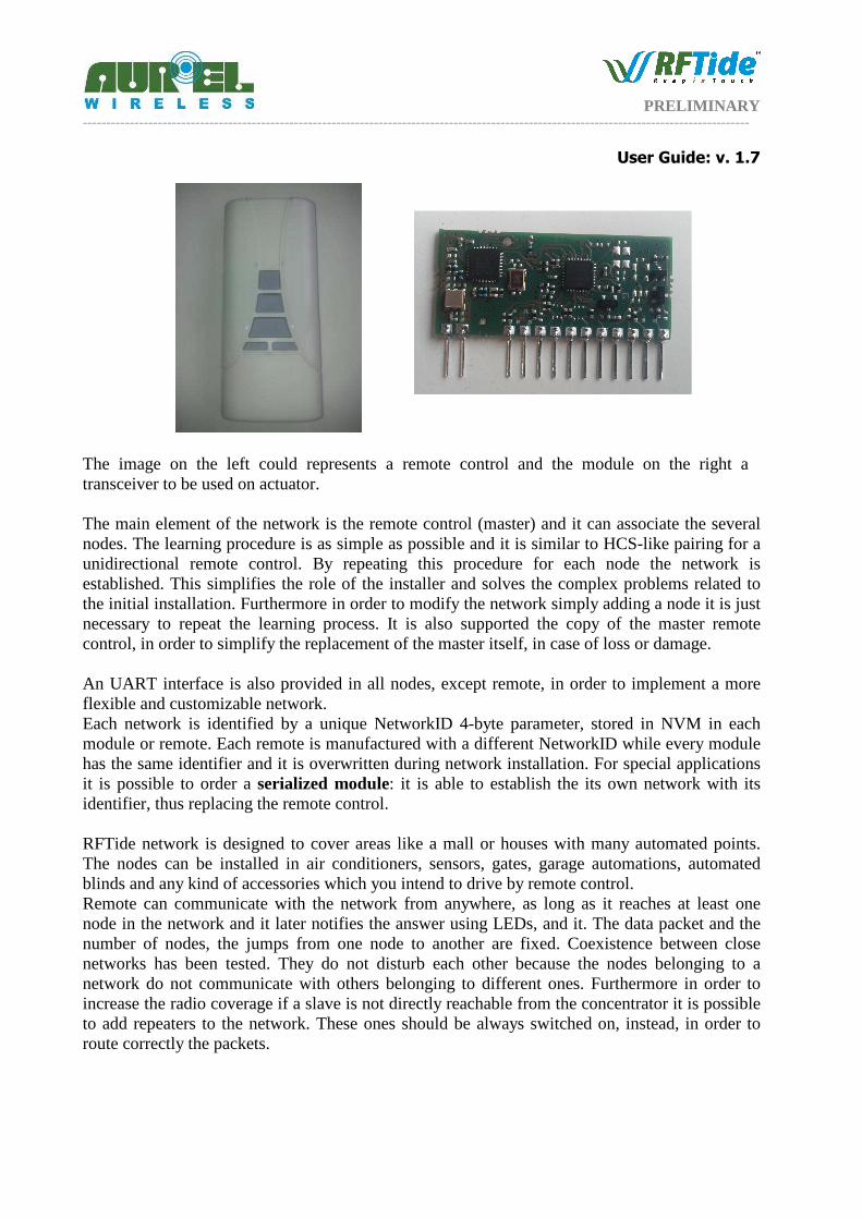
The image on the left could represents a remote control and the module on the right a transceiver to be used on actuator. The main element of the network is the remote control (master) and it can associate the several nodes. The learning procedure is as simple as possible and it is similar to HCS-like pairing for a unidirectional remote control. By repeating this procedure for each node the network is established. This simplifies the role of the installer and solves the complex problems related to the initial installation. Furthermore in order to modify the network simply adding a node it is just necessary to repeat the learning process. It is also supported the copy of the master remote control, in order to simplify the replacement of the master itself, in case of loss or damage. An UART interface is also provided in all nodes, except remote, in order to implement a more flexible and customizable network. Each network is identified by a unique NetworkID 4-byte parameter, stored in NVM in each module or remote. Each remote is manufactured with a different NetworkID while every module has the same identifier and it is overwritten during network installation. For special applications it is possible to order a serialized module: it is able to establish the its own network with its identifier, thus replacing the remote control. RFTide network is designed to cover areas like a mall or houses with many automated points. The nodes can be installed in air conditioners, sensors, gates, garage automations, automated blinds and any kind of accessories which you intend to drive by remote control. Remote can communicate with the network from anywhere, as long as it reaches at least one node in the network and it later notifies the answer using LEDs, and it. The data packet and the number of nodes, the jumps from one node to another are fixed. Coexistence between close networks has been tested. They do not disturb each other because the nodes belonging to a network do not communicate with others belonging to different ones. Furthermore in order to increase the radio coverage if a slave is not directly reachable from the concentrator it is possible to add repeaters to the network. These ones should be always switched on, instead, in order to route correctly the packets.

PRELIMINARY ----------------------------------------------------------------------------------------------------------------------------------------------
User Guide: v. 1.7
Various profiles have been already implemented in RFTide modules in order to set-up some simple applications with no need for further complex component:
• MOTOR profile: a module can used to drive a bidirectional motor and a support for two limit switches. Thus it is possible to achieve information about the position of the motor
• PWM profile: in this case a module cha drive a light source (e.g. a led) using a PWM modulation. In order to appreciate the different light levels the various steps are designed according to a exponential law. It is also possible to
• Wireless metering profile: In this profile every node periodically sends data (e.g. room temperature, door opening information) to the concentrator, equipped with a dedicated module. Thus it is possible to make each slave node to sleep most of the time and they can be battery operated.
By default a node does not belong to any profile.
PRELIMINARY ----------------------------------------------------------------------------------------------------------------------------------------------
User Guide: v. 1.7
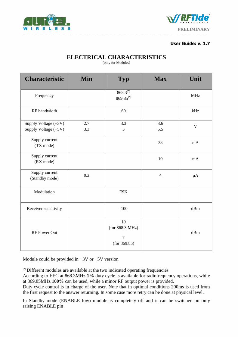
ELECTRICAL CHARACTERISTICS (only for Modules)
Characteristic Min Typ Max Unit
Frequency 868.3(*) 869.85(*)
MHz
RF bandwidth 60 kHz
Supply Voltage (+3V) Supply Voltage (+5V)
2.7 3.3
3.3 5
3.6 5.5
V
Supply current (TX mode)
33 mA
Supply current (RX mode)
10 mA
Supply current (Standby mode)
0.2 4 µA
Modulation FSK
Receiver sensitivity -100 dBm
RF Power Out
10 (for 868.3 MHz)
7 (for 869.85)
dBm
Module could be provided in +3V or +5V version (*) Different modules are available at the two indicated operating frequencies According to EEC at 868.3MHz 1% duty cycle is available for radiofrequency operations, while at 869.85MHz 100% can be used, while a minor RF output power is provided. Duty-cycle control is in charge of the user. Note that in optimal conditions 200ms is used from the first request to the answer returning. In some case more retry can be done at physical level.
In Standby mode (ENABLE low) module is completely off and it can be switched on only raising ENABLE pin
PRELIMINARY ----------------------------------------------------------------------------------------------------------------------------------------------
User Guide: v. 1.7
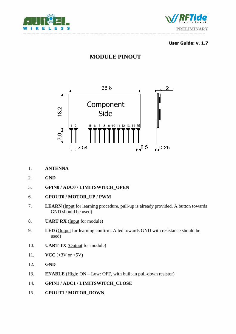
MODULE PINOUT
1. ANTENNA
2. GND
5. GPIN0 / ADC0 / LIMITSWITCH_OPEN
6. GPOUT0 / MOTOR_UP / PWM
7. LEARN (Input for learning procedure, pull-up is already provided. A button towards GND should be used)
8. UART RX (Input for module)
9. LED (Output for learning confirm. A led towards GND with resistance should be used)
10. UART TX (Output for module)
11. VCC (+3V or +5V)
12. GND
13. ENABLE (High: ON – Low: OFF, with built-in pull-down resistor)
14. GPIN1 / ADC1 / LIMITSWITCH_CLOSE
15. GPOUT1 / MOTOR_DOWN

PRELIMINARY ----------------------------------------------------------------------------------------------------------------------------------------------
User Guide: v. 1.7
PRELIMINARY ----------------------------------------------------------------------------------------------------------------------------------------------
User Guide: v. 1.7
I/O STAGES
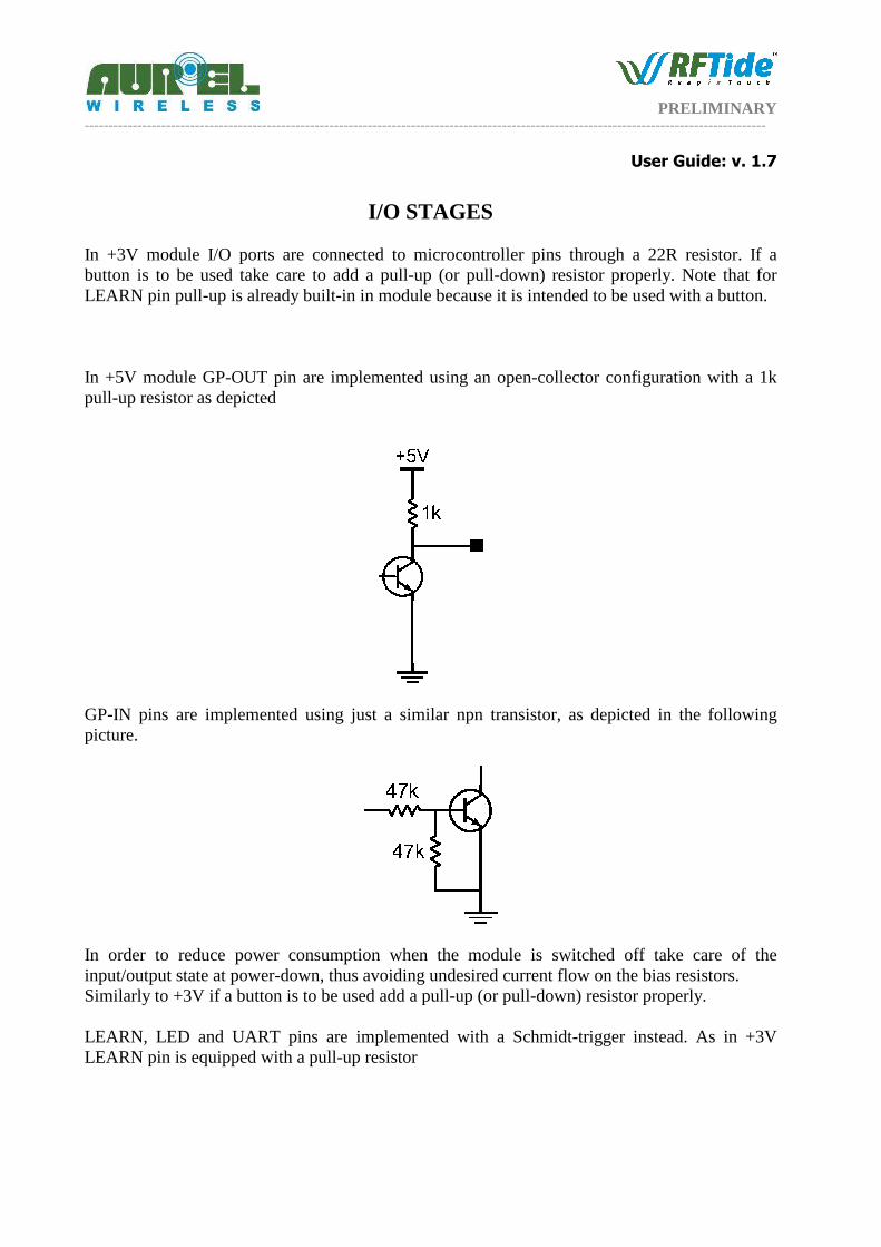
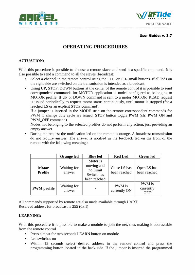
In +3V module I/O ports are connected to microcontroller pins through a 22R resistor. If a button is to be used take care to add a pull-up (or pull-down) resistor properly. Note that for LEARN pin pull-up is already built-in in module because it is intended to be used with a button. In +5V module GP-OUT pin are implemented using an open-collector configuration with a 1k pull-up resistor as depicted
GP-IN pins are implemented using just a similar npn transistor, as depicted in the following picture.
In order to reduce power consumption when the module is switched off take care of the input/output state at power-down, thus avoiding undesired current flow on the bias resistors. Similarly to +3V if a button is to be used add a pull-up (or pull-down) resistor properly. LEARN, LED and UART pins are implemented with a Schmidt-trigger instead. As in +3V LEARN pin is equipped with a pull-up resistor

PRELIMINARY ----------------------------------------------------------------------------------------------------------------------------------------------
User Guide: v. 1.7
RF CONSIDERATIONS 50 Ohm line:
1. It must be the shortest as possible. 2. 1.8 mm wide for 1 mm thick FR4 printed circuits and 2.9 mm wide for 1.6 mm thick FR4
printed circuits. It must be kept 2 mm away from the ground circuit on the same side. 3. On the opposite side a ground circuit area must be present.
Antenna connection:
1. It may be utilized as the direct connection point for the radiating whip antenna. 2. It can bear the connection of the central wire of a 50Ω coaxial cable. Be sure that the
braid is welded to the ground in a close point. Antenna
1. A whip antenna, 8.5 cm long and approximately 1 mm diameter, brass or copper wire made, must be connected to the RF output of the transmitter
2. The antenna body must be keep straight as much as possible and it must be free from other circuits or metal parts (5 cm minimum suggested distance.)
3. It can be utilized either vertically or horizontally, provided that a good ground plane surrounds the connection point between antenna and transmitter output.
N.B.: As an alternative to the a.m. antenna it is possible to fit the whip model manufactured by AUR°EL (see related Data Sheet and Application Notes). By fitting whips too different from the described ones, the EEC Certification is not assured.
PRELIMINARY ----------------------------------------------------------------------------------------------------------------------------------------------
User Guide: v. 1.7
OPERATING PROCEDURES ACTUATION: With this procedure it possible to choose a remote slave and send it a specific command. It is also possible to send a command to all the slaves (broadcast)
• Select a channel in the remote control using the CH+ or CH- small buttons. If all leds on the right side are switched on the transmission is intended as a broadcast.
• Using UP, STOP, DOWN buttons at the center of the remote control it is possible to send correspondent commands for MOTOR application to nodes configured as belonging to MOTOR profile. If UP or DOWN command is sent to a motor MOTOR_READ request is issued periodically to request motor status continuously, until motor is stopped (for a reached LS or an explicit STOP command). If a jumper is inserted in the MODE strip on the remote correspondent commands for PWM to change duty cycle are issued. STOP button toggle PWM (cfr. PWM_ON and PWM_OFF command). Nodes not belonging to the selected profiles do not perform any action, just providing an empty answer.
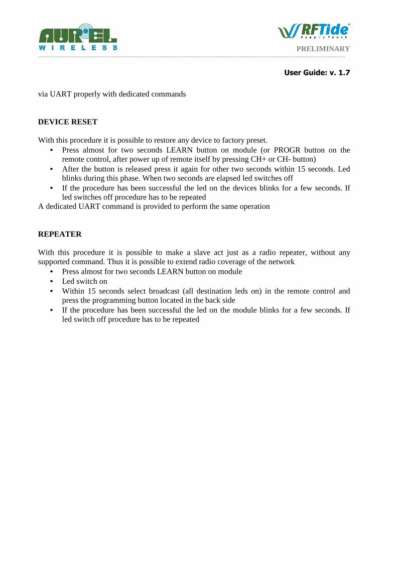
• During the request the notification led on the remote is orange. A broadcast transmission do not require answer. The answer is notified in the feedback led on the front of the remote with the following meanings:
Orange led Blue led Red Led Green led
Motor Profile
Waiting for answer
Motor is moving and
no Limit Switch has
been reached
Close LS has been reached
Open LS has been reached
PWM profile Waiting for
answer -
PWM is currently ON
PWM is currently
OFF All commands supported by remote are also made available through UART Reserved address for broadcast is 255 (0xff) LEARNING: With this procedure it is possible to make a module to join the net, thus making it addressable from the remote control
• Press almost for two seconds LEARN button on module • Led switches on • Within 15 seconds select desired address in the remote control and press the
programming button located in the back side. If the jumper is inserted the programmed

PRELIMINARY ----------------------------------------------------------------------------------------------------------------------------------------------
User Guide: v. 1.7
node is configured as belonging to PWM profile, otherwise it is configured as belonging to MOTOR profile
• If the procedure has been successful the led on the module blinks for a few seconds. If the led switches off procedure has to be repeated. No answer is provided to remote
The same procedure can be done using a specific serialized module (same hardware, specific firmware) replacing the role of the remote control. This module is in charge to form the network using the dedicated PROGR_MESSAGE command issue via UART. (Note that address = 0 is reserved for keyfob devices) REMOTE CLONING With this procedure it is possible to copy data from a remote control to another one. Thus also this additional remote is able to communicate to all the nodes of the network.
• Turn on remote pressing CH+ or CH- button • Press almost for two seconds PROGR button on remote All leds switch on • Turn on remote control to be copied and press the programming button located in the
back side. Do not care about the selected channel • If the procedure has been successful the leds on the remote blinks for a few seconds. If
all leds switch off procedure has to be repeated SENSOR It is possible to program a module to send unsolicited commands to other modules (e.g.: A wind sensor should close all curtain around home)
• Press almost for two seconds LEARN button on module. • Led switches on • Turn on remote pressing CH+ or CH- button • Press PROGR2 on the remote, thus sending PROGR_SENSOR_MESSAGE, in order to
instruct the node as a sensor • If the procedure has been successful the led on the device blinks for a few seconds. If the
led switches off procedure has to be repeated. No answer is provided to remote • Press again LEARN button and perform desired operation from the remote. The
operation is actually executed for a visual check and it is stored in the sensor node. Only operations issued from the node who instructed the node as a sensor are considered valid. Note that all remotes have the same address (0x00)
• It is possible to store up to three different operations. All these operations are executed in case an event is triggered in the sensor.
• To trigger an event lower GPIN0 pin on module Any sensor is learned with address 254 (0xfe) To change the stored operations reset the device as follows, thus restoring the factory settings, and repeat the whole procedure. Remote could be replaced by any network module, controlled
PRELIMINARY ----------------------------------------------------------------------------------------------------------------------------------------------
User Guide: v. 1.7
via UART properly with dedicated commands DEVICE RESET With this procedure it is possible to restore any device to factory preset.
• Press almost for two seconds LEARN button on module (or PROGR button on the remote control, after power up of remote itself by pressing CH+ or CH- button)
• After the button is released press it again for other two seconds within 15 seconds. Led blinks during this phase. When two seconds are elapsed led switches off
• If the procedure has been successful the led on the devices blinks for a few seconds. If led switches off procedure has to be repeated
A dedicated UART command is provided to perform the same operation REPEATER With this procedure it is possible to make a slave act just as a radio repeater, without any supported command. Thus it is possible to extend radio coverage of the network
• Press almost for two seconds LEARN button on module • Led switch on • Within 15 seconds select broadcast (all destination leds on) in the remote control and
press the programming button located in the back side • If the procedure has been successful the led on the module blinks for a few seconds. If
led switch off procedure has to be repeated

PRELIMINARY ----------------------------------------------------------------------------------------------------------------------------------------------
User Guide: v. 1.7
UART PROTOCOL In order to control data exchange from an external microcontroller it is possible to send commands through a serial port using an external microcontroller or a PC.
• Baud Rate: 19200 • Bits: 8 • Parity: None • Stop bits: 1
Each command sent through serial port is composed as follows:
Cmd LSB
Cmd MSB
Address Byte
0 Byte
1 Byte
2 Byte
3 Byte
4 Byte
5 Byte
6 Byte
7
First two bytes indicate the command (Cmd) to be executed Address indicate the address of the node, to which the command should be sent. In case a packet is sent from Aurel module the Address field contains the address of the node which originated the communication The following diagram shows the succession of the events for a standard communication:
A communication is started through the issue of a generic command through the UART from the external microcontroller to Aurel module. The packet is delivered through the network to the destination node and it is redirected to UART. Successively a answer packet (Command: ANSWER, with a specific answer payload) returns to the first node and it is also redirected to UART. In case it is necessary to send a broadcast command the 0xFF address should be used. In this case no return RF transmission and answer message is expected (steps 4 and 5).
Step 1 – UART to AUREL Module
Cmd: Generic Command
Step 3 - UART from
AUREL Module
Cmd: Generic Command
Address: 0x1A
Node
0x1A Node
0x2B
Step 4 – RF Transmission
Step 2 – RF Transmission
Step 5 – UART from AUREL Module
Cmd: ANSWER
PRELIMINARY ----------------------------------------------------------------------------------------------------------------------------------------------
User Guide: v. 1.7
COMMAND TABLES
System commands:
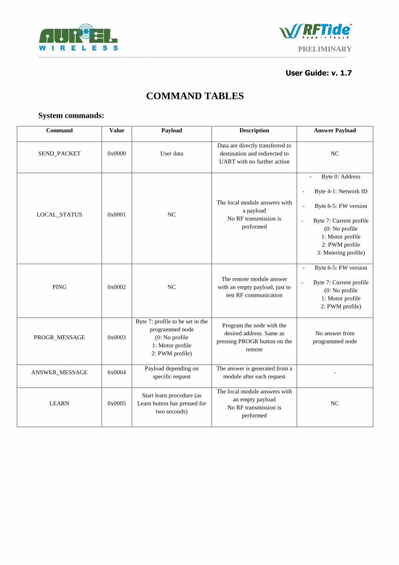
Command Value Payload Description Answer Payload
SEND_PACKET 0x0000 User data Data are directly transferred to destination and redirected to UART with no further action
NC
LOCAL_STATUS 0x0001 NC
The local module answers with a payload
No RF transmission is performed
- Byte 0: Address
- Byte 4-1: Network ID
- Byte 6-5: FW version
- Byte 7: Current profile (0: No profile
1: Motor profile 2: PWM profile
3: Metering profile)
PING 0x0002 NC The remote module answer
with an empty payload, just to test RF communication
- Byte 6-5: FW version
- Byte 7: Current profile (0: No profile
1: Motor profile 2: PWM profile)
PROGR_MESSAGE 0x0003
Byte 7: profile to be set in the programmed node
(0: No profile 1: Motor profile 2: PWM profile)
Program the node with the desired address. Same as
pressing PROGR button on the remote
No answer from programmed node
ANSWER_MESSAGE 0x0004 Payload depending on
specific request The answer is generated from a
module after each request -
LEARN 0x0005 Start learn procedure (as
Learn button has pressed for two seconds)
The local module answers with an empty payload
No RF transmission is performed
NC
PRELIMINARY ----------------------------------------------------------------------------------------------------------------------------------------------
User Guide: v. 1.7
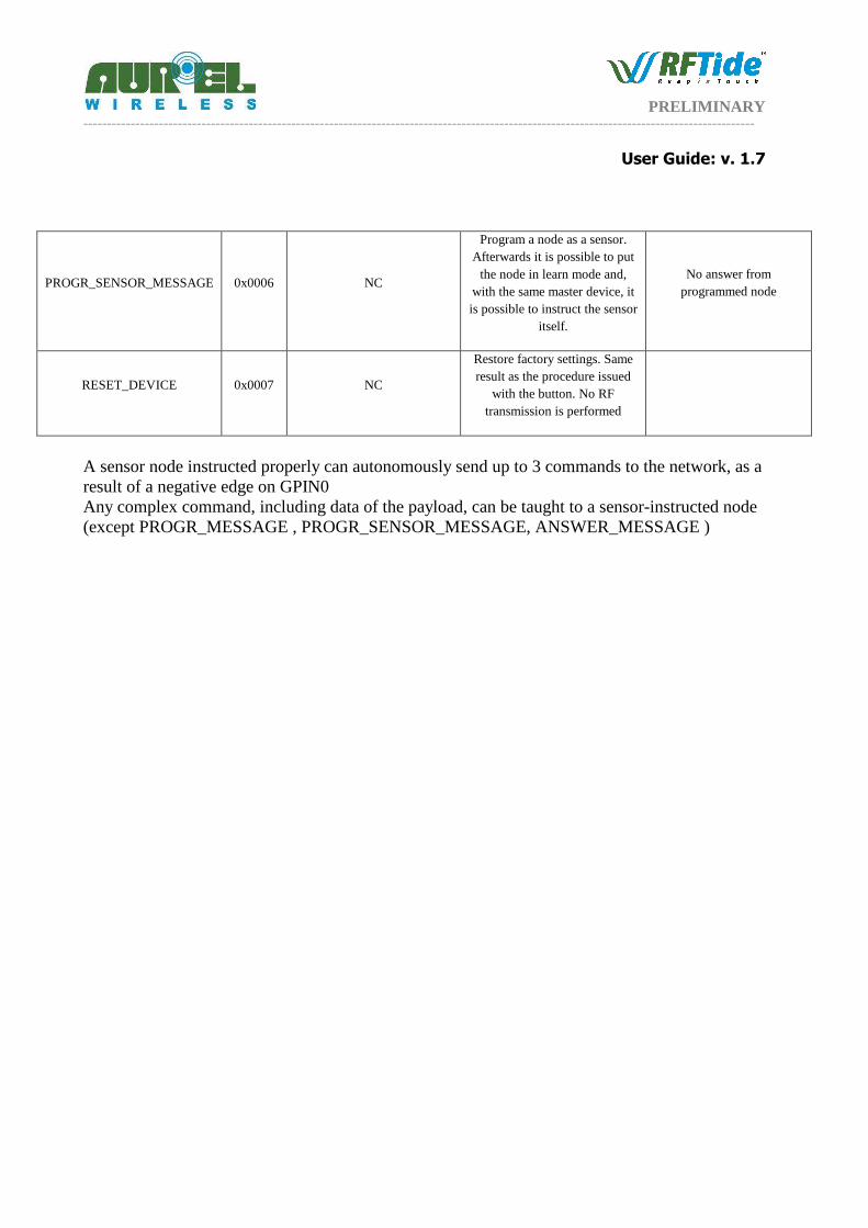
PROGR_SENSOR_MESSAGE 0x0006 NC
Program a node as a sensor. Afterwards it is possible to put
the node in learn mode and, with the same master device, it is possible to instruct the sensor
itself.
No answer from programmed node
RESET_DEVICE 0x0007 NC
Restore factory settings. Same result as the procedure issued
with the button. No RF transmission is performed
A sensor node instructed properly can autonomously send up to 3 commands to the network, as a result of a negative edge on GPIN0 Any complex command, including data of the payload, can be taught to a sensor-instructed node (except PROGR_MESSAGE , PROGR_SENSOR_MESSAGE, ANSWER_MESSAGE )
PRELIMINARY ----------------------------------------------------------------------------------------------------------------------------------------------
User Guide: v. 1.7
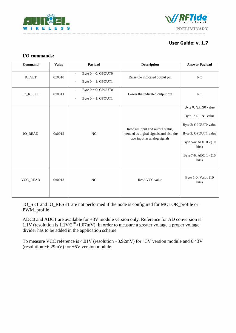
I/O commands: Command Value Payload Description Answer Payload
IO_SET 0x0010 - Byte 0 = 0: GPOUT0
- Byte 0 = 1: GPOUT1 Raise the indicated output pin NC
IO_RESET 0x0011 - Byte 0 = 0: GPOUT0
- Byte 0 = 1: GPOUT1 Lower the indicated output pin NC
IO_READ 0x0012 NC Read all input and output status,
intended as digital signals and also the two input as analog signals
Byte 0: GPIN0 value
Byte 1: GPIN1 value
Byte 2: GPOUT0 value
Byte 3: GPOUT1 value
Byte 5-4: ADC 0 - (10 bits)
Byte 7-6: ADC 1 - (10 bits)
VCC_READ 0x0013 NC Read VCC value Byte 1-0: Value (10
bits)
IO_SET and IO_RESET are not performed if the node is configured for MOTOR_profile or PWM_profile
ADC0 and ADC1 are available for +3V module version only. Reference for AD conversion is 1.1V (resolution is 1.1V/210
≈1.07mV). In order to measure a greater voltage a proper voltage divider has to be added in the application scheme To measure VCC reference is 4.01V (resolution ~3.92mV) for +3V version module and 6.43V (resolution ~6.29mV) for +5V version module.
PRELIMINARY ----------------------------------------------------------------------------------------------------------------------------------------------
User Guide: v. 1.7
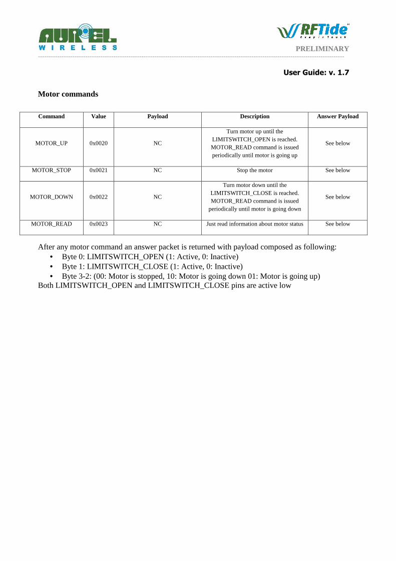
Motor commands
Command Value Payload Description Answer Payload
MOTOR_UP 0x0020 NC
Turn motor up until the LIMITSWITCH_OPEN is reached. MOTOR_READ command is issued periodically until motor is going up
See below
MOTOR_STOP 0x0021 NC Stop the motor See below
MOTOR_DOWN 0x0022 NC
Turn motor down until the LIMITSWITCH_CLOSE is reached. MOTOR_READ command is issued
periodically until motor is going down
See below
MOTOR_READ 0x0023 NC Just read information about motor status See below
After any motor command an answer packet is returned with payload composed as following: • Byte 0: LIMITSWITCH_OPEN (1: Active, 0: Inactive) • Byte 1: LIMITSWITCH_CLOSE (1: Active, 0: Inactive) • Byte 3-2: (00: Motor is stopped, 10: Motor is going down 01: Motor is going up)
Both LIMITSWITCH_OPEN and LIMITSWITCH_CLOSE pins are active low
PRELIMINARY ----------------------------------------------------------------------------------------------------------------------------------------------
User Guide: v. 1.7
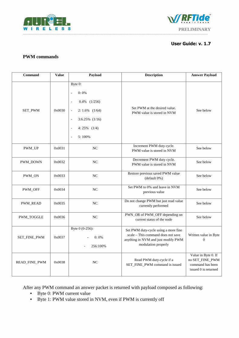
PWM commands
Command Value Payload Description Answer Payload
SET_PWM 0x0030
Byte 0:
- 0: 0%
- 0.4% (1/256)
- 2: 1.6% (1/64)
- 3:6.25% (1/16)
- 4: 25% (1/4)
- 5: 100%
Set PWM at the desired value. PWM value is stored in NVM
See below
PWM_UP 0x0031 NC Increment PWM duty cycle.
PWM value is stored in NVM See below
PWM_DOWN 0x0032 NC Decrement PWM duty cycle. PWM value is stored in NVM
See below
PWM_ON 0x0033 NC Restore previous saved PWM value
(default 0%) See below
PWM_OFF 0x0034 NC Set PWM to 0% and leave in NVM
previous value See below
PWM_READ 0x0035 NC Do not change PWM but just read value
currently performed See below
PWM_TOGGLE 0x0036 NC PWN_OR of PWM_OFF depending on
current status of the node See below
SET_FINE_PWM 0x0037
Byte 0 (0-256):
- 0: 0%
- 256:100%
Set PWM duty-cycle using a more fine scale – This command does not save
anything in NVM and just modify PWM modulation properly
Written value in Byte 0
READ_FINE_PWM 0x0038 NC Read PWM duty-cycle if a
SET_FINE_PWM command is issued
Value in Byte 0. If no SET_FINE_PWM command has been issued 0 is returned
After any PWM command an answer packet is returned with payload composed as following: • Byte 0: PWM current value • Byte 1: PWM value stored in NVM, even if PWM is currently off
PRELIMINARY ----------------------------------------------------------------------------------------------------------------------------------------------
User Guide: v. 1.7
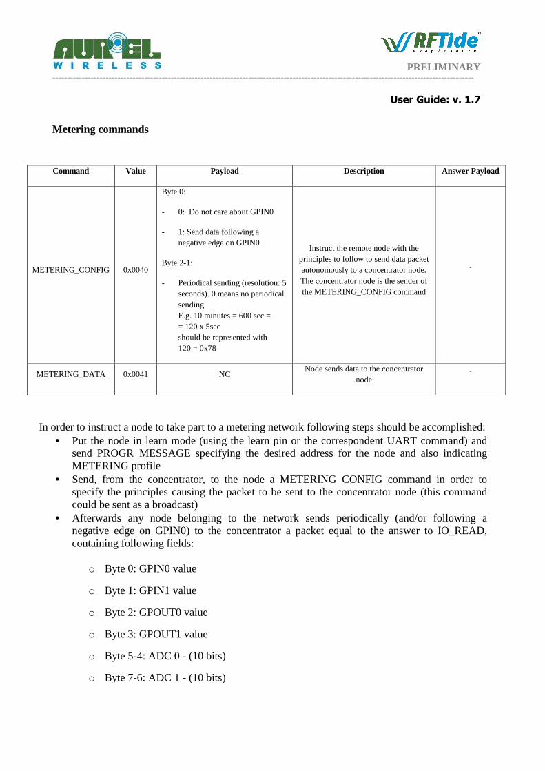
Metering commands
Command Value Payload Description Answer Payload
METERING_CONFIG 0x0040
Byte 0:
- 0: Do not care about GPIN0
- 1: Send data following a negative edge on GPIN0
Byte 2-1:
- Periodical sending (resolution: 5 seconds). 0 means no periodical sending E.g. 10 minutes = 600 sec = = 120 x 5sec should be represented with 120 = 0x78
Instruct the remote node with the principles to follow to send data packet autonomously to a concentrator node. The concentrator node is the sender of the METERING_CONFIG command
-
METERING_DATA 0x0041 NC Node sends data to the concentrator
node -
In order to instruct a node to take part to a metering network following steps should be accomplished:
• Put the node in learn mode (using the learn pin or the correspondent UART command) and send PROGR_MESSAGE specifying the desired address for the node and also indicating METERING profile
• Send, from the concentrator, to the node a METERING_CONFIG command in order to specify the principles causing the packet to be sent to the concentrator node (this command could be sent as a broadcast)
• Afterwards any node belonging to the network sends periodically (and/or following a negative edge on GPIN0) to the concentrator a packet equal to the answer to IO_READ, containing following fields:
o Byte 0: GPIN0 value
o Byte 1: GPIN1 value
o Byte 2: GPOUT0 value
o Byte 3: GPOUT1 value
o Byte 5-4: ADC 0 - (10 bits)
o Byte 7-6: ADC 1 - (10 bits)
PRELIMINARY ----------------------------------------------------------------------------------------------------------------------------------------------
User Guide: v. 1.7
In order to reduce power consumption a node can be instructed just to send after GPIN0 negative edge, afterwards it can be switched off lowering EN pin. When a data should be sent raise EN and after 200 ms lower GPIN0 to send the packet to the concentrator. In order to reduce packet collision an initial time displacement depending on the address of the node is used. At the moment A blink on LED indicates the correct sending of the packet.

PRELIMINARY ----------------------------------------------------------------------------------------------------------------------------------------------
User Guide: v. 1.7
AVAILABLE PRODUCTS
Modules
Modules can be provided in the following variants:
− Ordering Code: 650201276G AUR.EL RFT-868-3V − Ordering Code: 650201274G AUR.EL RFT-868-3V 869.85 − Ordering Code: 650201275G AUR.EL RFT-868-3V Serialized − Ordering Code: 650201273G AUR.EL RFT-868-3V Serialized 869.85 − Ordering Code: 650201280G AUR.EL RFT-868-5V − Ordering Code: 650201278G AUR.EL RFT-868-5V 869.85 − Ordering Code: 650201279G AUR.EL RFT-868-5V Serialized − Ordering Code: 650201277G AUR.EL RFT-868-5V Serialized 869.85
Pinout and electrical characteristics have been described in the previous pages Remember that all modules belonging to the same network must have the same operating frequency, while it is possible to use 3V and 5V modules in the same network. Not serialized modules are provided with default NetworkID equal to 0x??????? and address ????
PRELIMINARY ----------------------------------------------------------------------------------------------------------------------------------------------
User Guide: v. 1.7
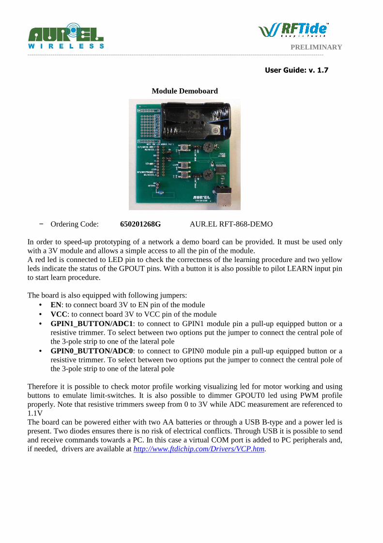
Module Demoboard
− Ordering Code: 650201268G AUR.EL RFT-868-DEMO In order to speed-up prototyping of a network a demo board can be provided. It must be used only with a 3V module and allows a simple access to all the pin of the module. A red led is connected to LED pin to check the correctness of the learning procedure and two yellow leds indicate the status of the GPOUT pins. With a button it is also possible to pilot LEARN input pin to start learn procedure. The board is also equipped with following jumpers:
• EN: to connect board 3V to EN pin of the module • VCC: to connect board 3V to VCC pin of the module • GPIN1_BUTTON/ADC1: to connect to GPIN1 module pin a pull-up equipped button or a
resistive trimmer. To select between two options put the jumper to connect the central pole of the 3-pole strip to one of the lateral pole
• GPIN0_BUTTON/ADC0: to connect to GPIN0 module pin a pull-up equipped button or a resistive trimmer. To select between two options put the jumper to connect the central pole of the 3-pole strip to one of the lateral pole
Therefore it is possible to check motor profile working visualizing led for motor working and using buttons to emulate limit-switches. It is also possible to dimmer GPOUT0 led using PWM profile properly. Note that resistive trimmers sweep from 0 to 3V while ADC measurement are referenced to 1.1V The board can be powered either with two AA batteries or through a USB B-type and a power led is present. Two diodes ensures there is no risk of electrical conflicts. Through USB it is possible to send and receive commands towards a PC. In this case a virtual COM port is added to PC peripherals and, if needed, drivers are available at http://www.ftdichip.com/Drivers/VCP.htm.
PRELIMINARY ----------------------------------------------------------------------------------------------------------------------------------------------
User Guide: v. 1.7
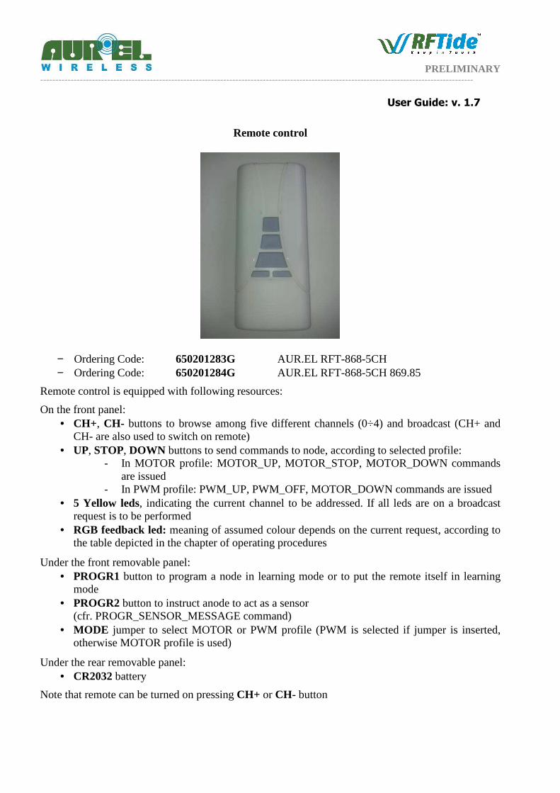
Remote control
− Ordering Code: 650201283G AUR.EL RFT-868-5CH − Ordering Code: 650201284G AUR.EL RFT-868-5CH 869.85
Remote control is equipped with following resources:
On the front panel: • CH+, CH- buttons to browse among five different channels (0÷4) and broadcast (CH+ and
CH- are also used to switch on remote) • UP, STOP, DOWN buttons to send commands to node, according to selected profile:
- In MOTOR profile: MOTOR_UP, MOTOR_STOP, MOTOR_DOWN commands are issued
- In PWM profile: PWM_UP, PWM_OFF, MOTOR_DOWN commands are issued • 5 Yellow leds, indicating the current channel to be addressed. If all leds are on a broadcast
request is to be performed • RGB feedback led: meaning of assumed colour depends on the current request, according to
the table depicted in the chapter of operating procedures
Under the front removable panel: • PROGR1 button to program a node in learning mode or to put the remote itself in learning
mode • PROGR2 button to instruct anode to act as a sensor
(cfr. PROGR_SENSOR_MESSAGE command) • MODE jumper to select MOTOR or PWM profile (PWM is selected if jumper is inserted,
otherwise MOTOR profile is used)
Under the rear removable panel: • CR2032 battery
Note that remote can be turned on pressing CH+ or CH- button
PRELIMINARY ----------------------------------------------------------------------------------------------------------------------------------------------
User Guide: v. 1.7
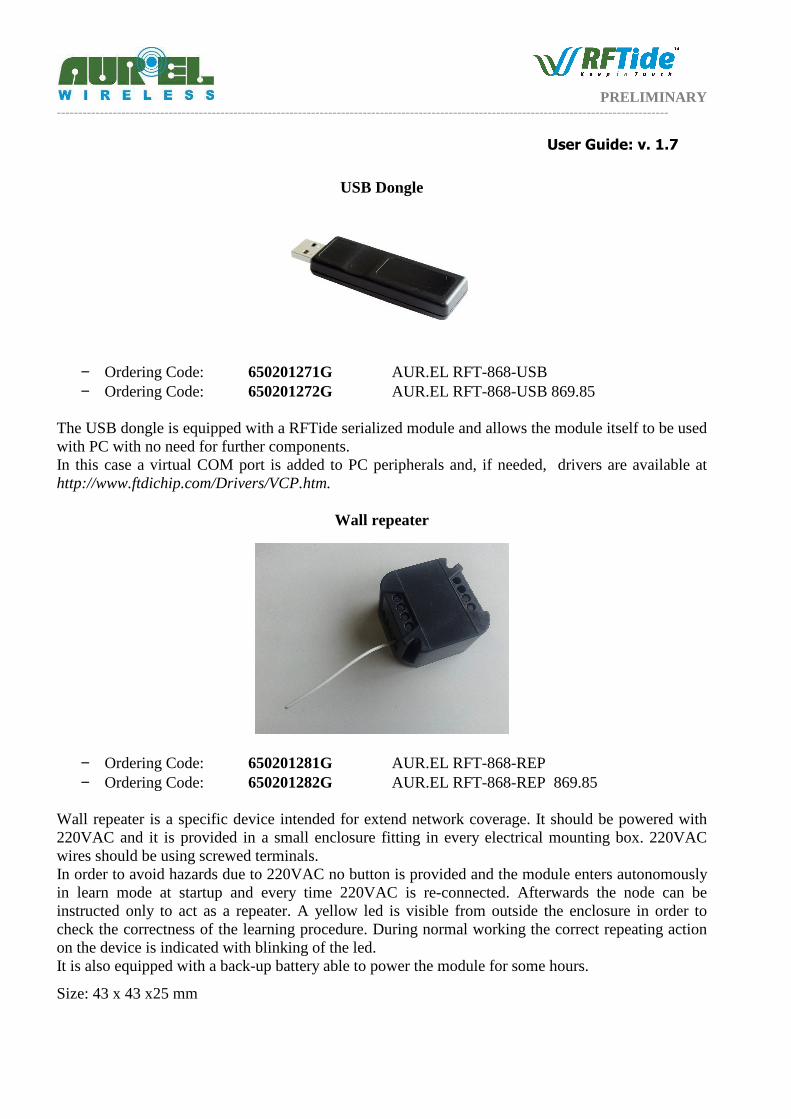
USB Dongle
− Ordering Code: 650201271G AUR.EL RFT-868-USB − Ordering Code: 650201272G AUR.EL RFT-868-USB 869.85
The USB dongle is equipped with a RFTide serialized module and allows the module itself to be used with PC with no need for further components. In this case a virtual COM port is added to PC peripherals and, if needed, drivers are available at http://www.ftdichip.com/Drivers/VCP.htm.
Wall repeater
− Ordering Code: 650201281G AUR.EL RFT-868-REP − Ordering Code: 650201282G AUR.EL RFT-868-REP 869.85
Wall repeater is a specific device intended for extend network coverage. It should be powered with 220VAC and it is provided in a small enclosure fitting in every electrical mounting box. 220VAC wires should be using screwed terminals. In order to avoid hazards due to 220VAC no button is provided and the module enters autonomously in learn mode at startup and every time 220VAC is re-connected. Afterwards the node can be instructed only to act as a repeater. A yellow led is visible from outside the enclosure in order to check the correctness of the learning procedure. During normal working the correct repeating action on the device is indicated with blinking of the led. It is also equipped with a back-up battery able to power the module for some hours.
Size: 43 x 43 x25 mm
PRELIMINARY ----------------------------------------------------------------------------------------------------------------------------------------------
User Guide: v. 1.7
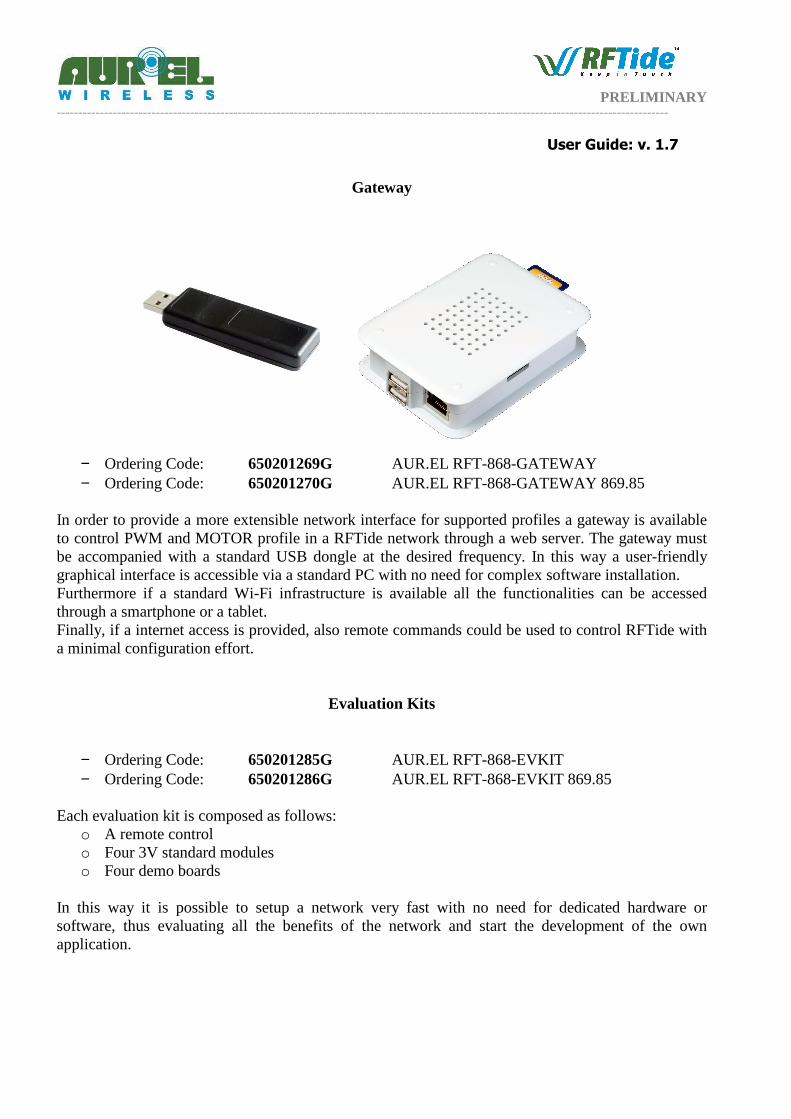
Gateway
− Ordering Code: 650201269G AUR.EL RFT-868-GATEWAY − Ordering Code: 650201270G AUR.EL RFT-868-GATEWAY 869.85
In order to provide a more extensible network interface for supported profiles a gateway is available to control PWM and MOTOR profile in a RFTide network through a web server. The gateway must be accompanied with a standard USB dongle at the desired frequency. In this way a user-friendly graphical interface is accessible via a standard PC with no need for complex software installation. Furthermore if a standard Wi-Fi infrastructure is available all the functionalities can be accessed through a smartphone or a tablet. Finally, if a internet access is provided, also remote commands could be used to control RFTide with a minimal configuration effort.
Evaluation Kits
− Ordering Code: 650201285G AUR.EL RFT-868-EVKIT − Ordering Code: 650201286G AUR.EL RFT-868-EVKIT 869.85
Each evaluation kit is composed as follows:
o A remote control o Four 3V standard modules o Four demo boards
In this way it is possible to setup a network very fast with no need for dedicated hardware or software, thus evaluating all the benefits of the network and start the development of the own application.