Embed Size (px)
Citation preview
AURORA PARTITION WALL SYSTEM
THE AL31 SERIES INSTALLATION INSTRUCTIONS [No.61]
© KOMANDOR S.A. Revision 10 dated 05.08.2015 r. page 1 / 50
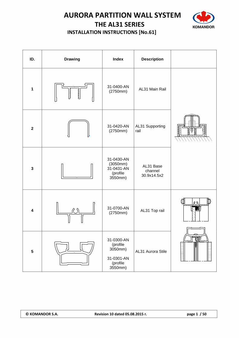
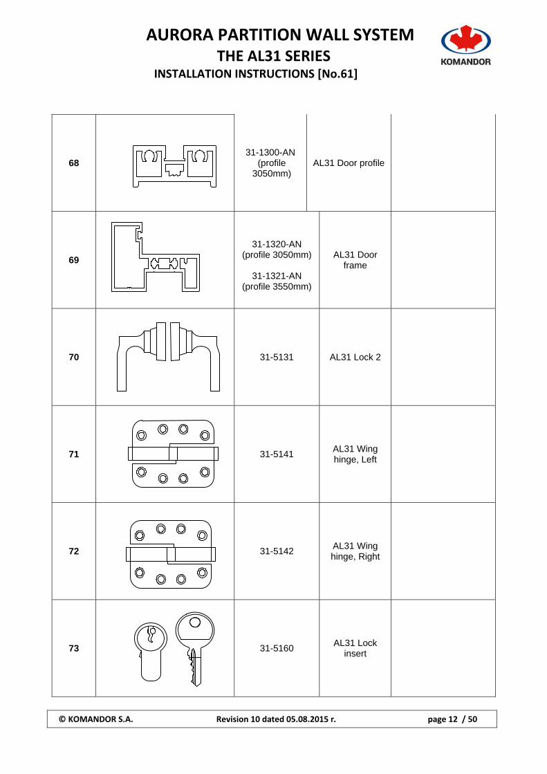
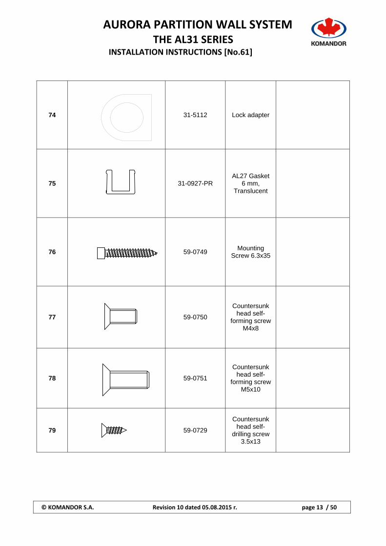
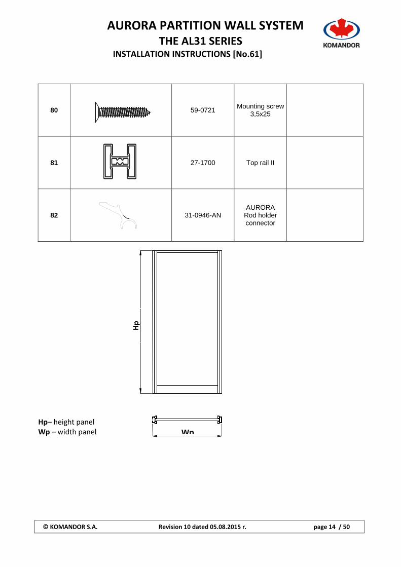
ID. Drawing Index Description
1
31-0400-AN (2750mm)
AL31 Main Rail
2 31-0420-AN (2750mm)
AL31 Supporting rail
3
31-0430-AN (3050mm)
31-0431-AN (profile
3550mm)
AL31 Base channel
30.9x14.5x2
4 31-0700-AN (2750mm)
AL31 Top rail
5
31-0300-AN
(profile 3050mm)
31-0301-AN
(profile 3550mm)
AL31 Aurora Stile
AURORA PARTITION WALL SYSTEM
THE AL31 SERIES INSTALLATION INSTRUCTIONS [No.61]
© KOMANDOR S.A. Revision 10 dated 05.08.2015 r. page 2 / 50
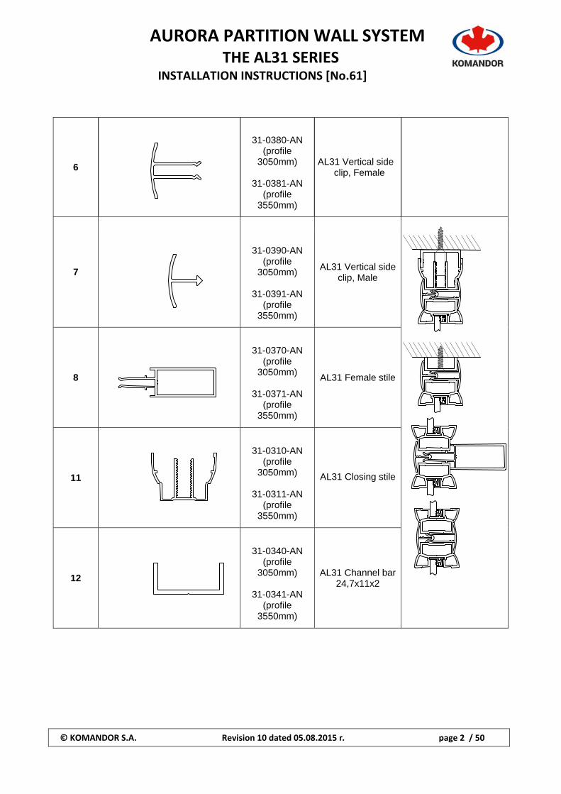
6
31-0380-AN (profile
3050mm)
31-0381-AN (profile
3550mm)
AL31 Vertical side clip, Female
7
31-0390-AN (profile
3050mm)
31-0391-AN (profile
3550mm)
AL31 Vertical side
clip, Male
8
31-0370-AN (profile
3050mm)
31-0371-AN (profile
3550mm)
AL31 Female stile
11
31-0310-AN (profile
3050mm)
31-0311-AN (profile
3550mm)
AL31 Closing stile
12
31-0340-AN
(profile 3050mm)
31-0341-AN
(profile 3550mm)
AL31 Channel bar 24,7x11x2
AURORA PARTITION WALL SYSTEM
THE AL31 SERIES INSTALLATION INSTRUCTIONS [No.61]
© KOMANDOR S.A. Revision 10 dated 05.08.2015 r. page 3 / 50
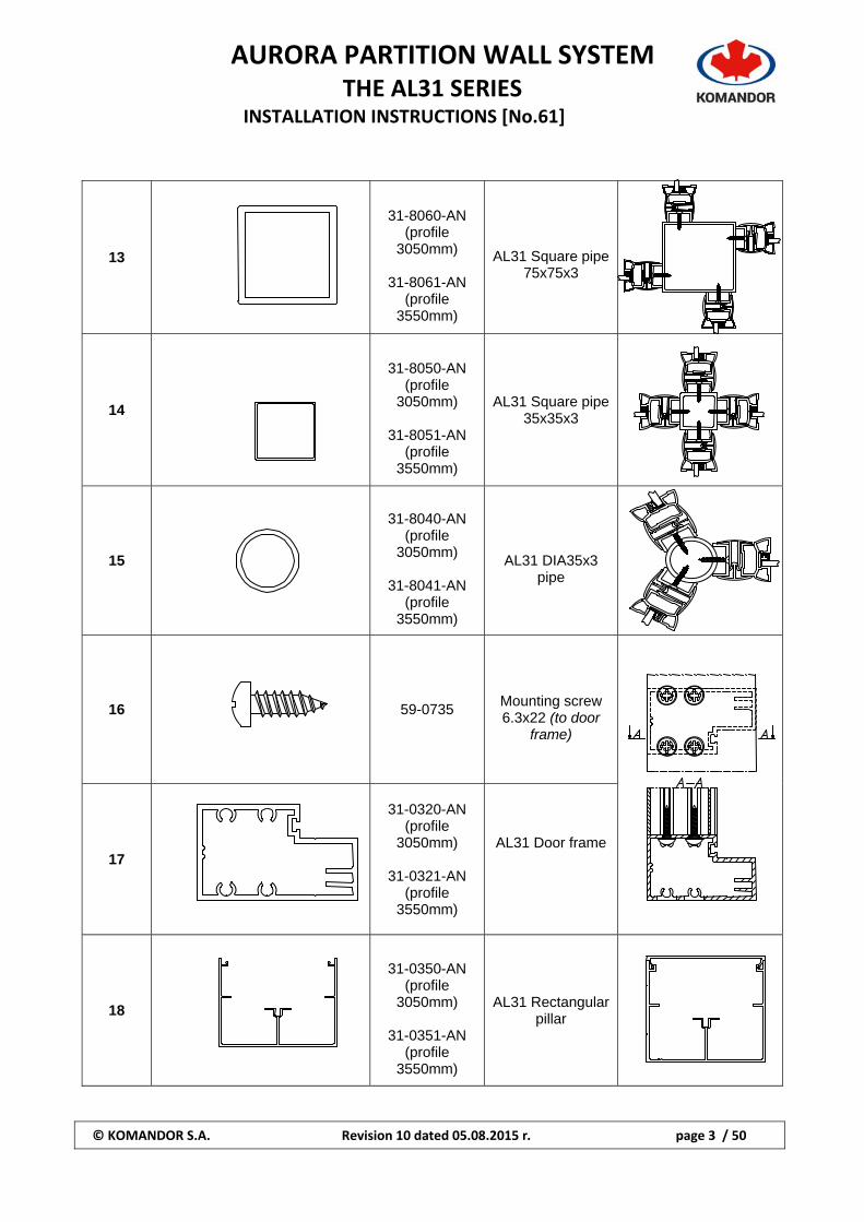
13
31-8060-AN
(profile 3050mm)
31-8061-AN
(profile 3550mm)
AL31 Square pipe 75x75x3
14
31-8050-AN
(profile 3050mm)
31-8051-AN
(profile 3550mm)
AL31 Square pipe
35x35x3
15
31-8040-AN
(profile 3050mm)
31-8041-AN
(profile 3550mm)
AL31 DIA35x3
pipe
16
59-0735
Mounting screw 6.3x22 (to door
frame)
17
31-0320-AN
(profile 3050mm)
31-0321-AN
(profile 3550mm)
AL31 Door frame
18
31-0350-AN
(profile 3050mm)
31-0351-AN
(profile 3550mm)
AL31 Rectangular pillar
AURORA PARTITION WALL SYSTEM
THE AL31 SERIES INSTALLATION INSTRUCTIONS [No.61]
© KOMANDOR S.A. Revision 10 dated 05.08.2015 r. page 4 / 50
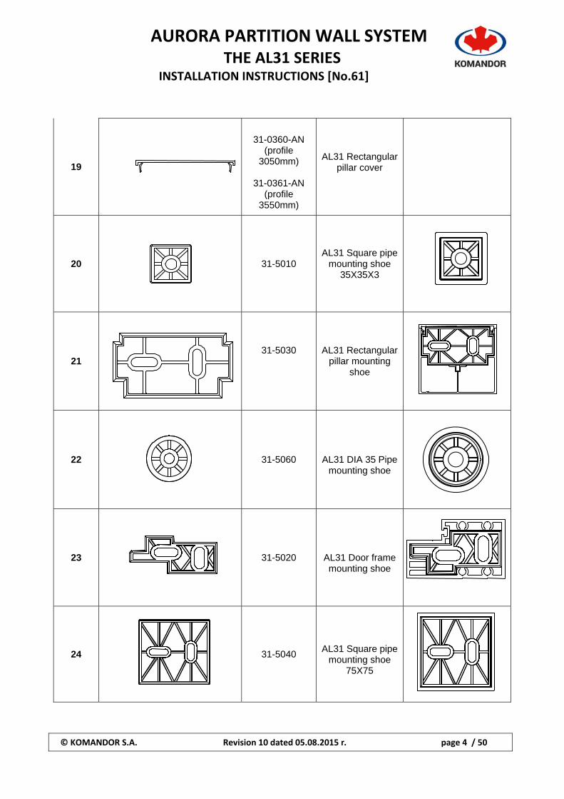
19
31-0360-AN
(profile 3050mm)
31-0361-AN
(profile 3550mm)
AL31 Rectangular pillar cover
20
31-5010 AL31 Square pipe
mounting shoe 35X35X3
21
31-5030
AL31 Rectangular pillar mounting
shoe
22
31-5060
AL31 DIA 35 Pipe mounting shoe
23
31-5020
AL31 Door frame mounting shoe
24
31-5040
AL31 Square pipe mounting shoe
75X75
AURORA PARTITION WALL SYSTEM
THE AL31 SERIES INSTALLATION INSTRUCTIONS [No.61]
© KOMANDOR S.A. Revision 10 dated 05.08.2015 r. page 5 / 50
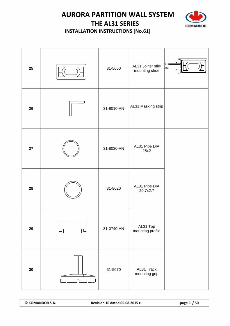
25 31-5050
AL31 Joiner stile mounting shoe
26
31-8010-AN AL31 Masking strip
27
31-8030-AN
AL31 Pipe DIA 25x2
28
31-8020
AL31 Pipe DIA 20.7x2.7
29
31-0740-AN AL31 Top
mounting profile
30
31-5070
AL31 Track mounting grip
AURORA PARTITION WALL SYSTEM
THE AL31 SERIES INSTALLATION INSTRUCTIONS [No.61]
© KOMANDOR S.A. Revision 10 dated 05.08.2015 r. page 6 / 50
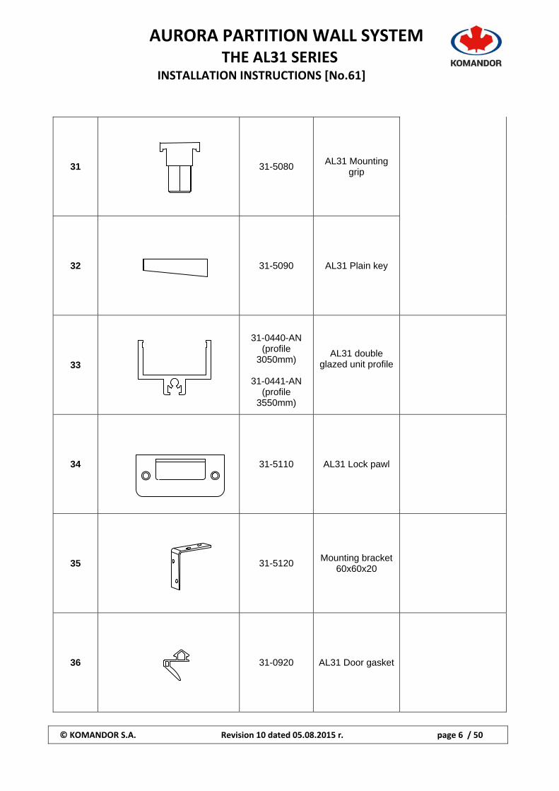
31
31-5080 AL31 Mounting
grip
32
31-5090 AL31 Plain key
33
31-0440-AN (profile
3050mm)
31-0441-AN (profile
3550mm)
AL31 double glazed unit profile
34 31-5110 AL31 Lock pawl
35
31-5120 Mounting bracket
60x60x20
36
31-0920 AL31 Door gasket
AURORA PARTITION WALL SYSTEM
THE AL31 SERIES INSTALLATION INSTRUCTIONS [No.61]
© KOMANDOR S.A. Revision 10 dated 05.08.2015 r. page 7 / 50
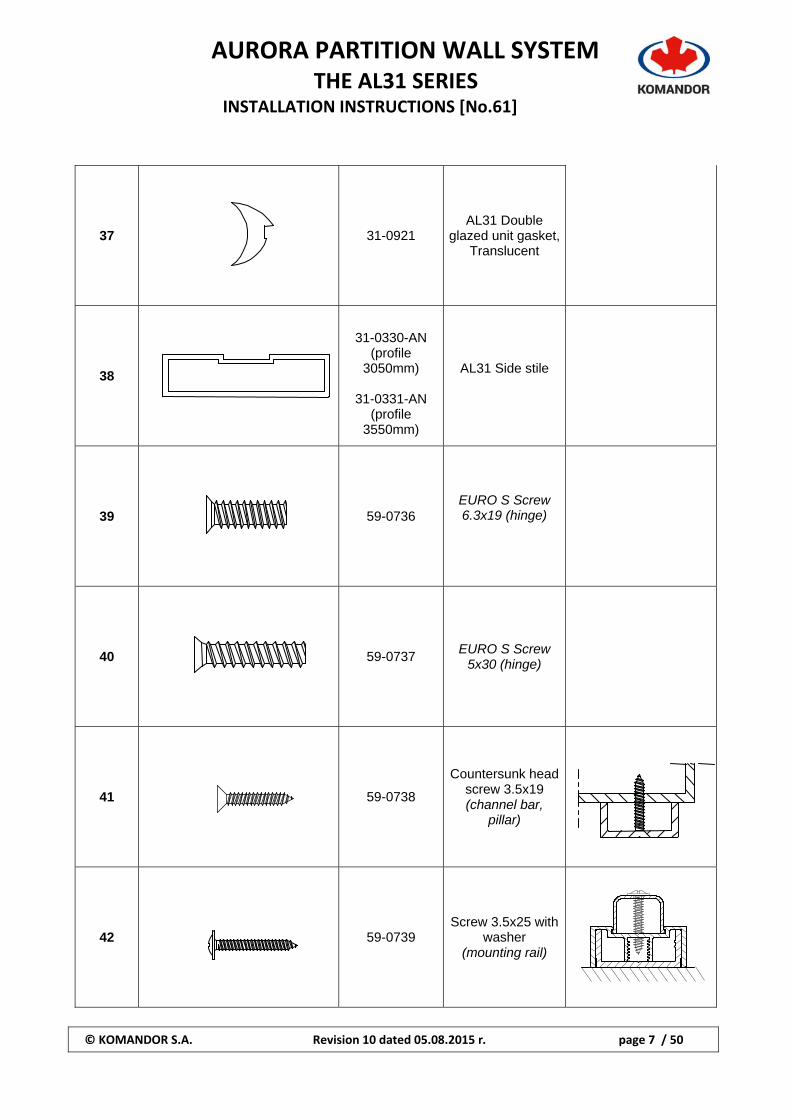
37
31-0921 AL31 Double
glazed unit gasket, Translucent
38
31-0330-AN (profile
3050mm)
31-0331-AN (profile
3550mm)
AL31 Side stile
39 59-0736
EURO S Screw 6.3x19 (hinge)
40
59-0737 EURO S Screw
5x30 (hinge)
41
59-0738
Countersunk head screw 3.5x19 (channel bar,
pillar)
42
59-0739 Screw 3.5x25 with
washer (mounting rail)
AURORA PARTITION WALL SYSTEM
THE AL31 SERIES INSTALLATION INSTRUCTIONS [No.61]
© KOMANDOR S.A. Revision 10 dated 05.08.2015 r. page 8 / 50
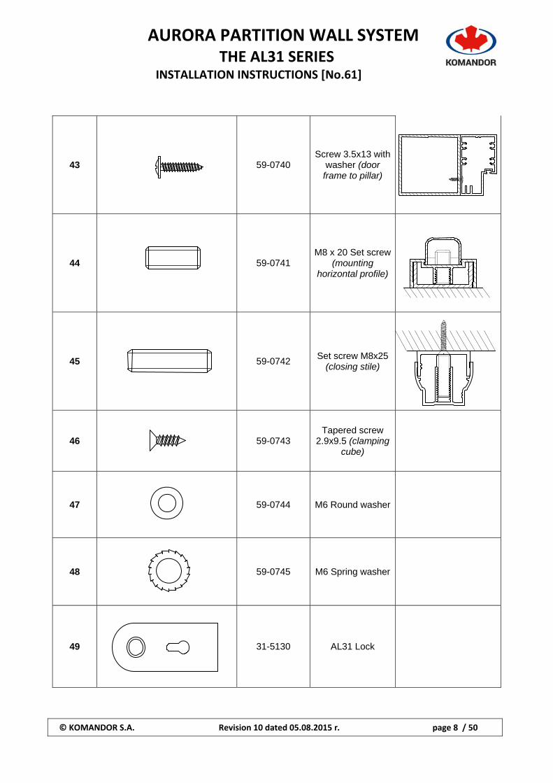
43
59-0740 Screw 3.5x13 with
washer (door frame to pillar)
44
59-0741 M8 x 20 Set screw
(mounting horizontal profile)
45
59-0742 Set screw M8x25
(closing stile)
46
59-0743 Tapered screw
2.9x9.5 (clamping cube)
47
59-0744 M6 Round washer
48
59-0745 M6 Spring washer
49
31-5130 AL31 Lock
AURORA PARTITION WALL SYSTEM
THE AL31 SERIES INSTALLATION INSTRUCTIONS [No.61]
© KOMANDOR S.A. Revision 10 dated 05.08.2015 r. page 9 / 50
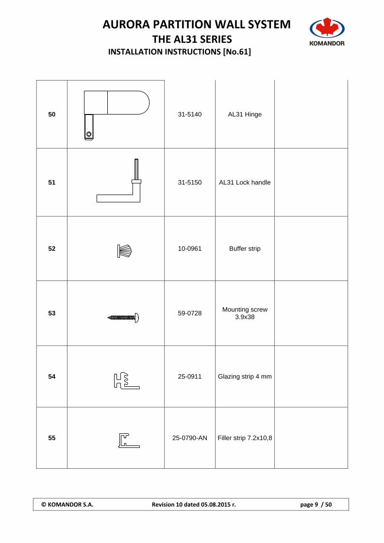
50
31-5140 AL31 Hinge
51
31-5150 AL31 Lock handle
52
10-0961 Buffer strip
53
59-0728 Mounting screw
3.9x38
54
25-0911 Glazing strip 4 mm
55
25-0790-AN Filler strip 7.2x10,8
AURORA PARTITION WALL SYSTEM
THE AL31 SERIES INSTALLATION INSTRUCTIONS [No.61]
© KOMANDOR S.A. Revision 10 dated 05.08.2015 r. page 10 / 50
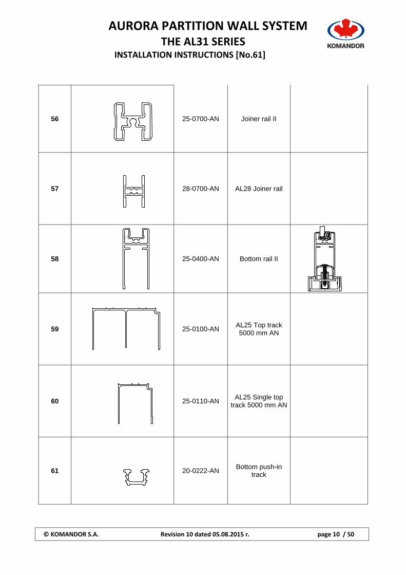
56
25-0700-AN Joiner rail II
57
28-0700-AN AL28 Joiner rail
58
25-0400-AN Bottom rail II
59
25-0100-AN AL25 Top track 5000 mm AN
60
25-0110-AN AL25 Single top
track 5000 mm AN
61
20-0222-AN Bottom push-in
track
AURORA PARTITION WALL SYSTEM
THE AL31 SERIES INSTALLATION INSTRUCTIONS [No.61]
© KOMANDOR S.A. Revision 10 dated 05.08.2015 r. page 11 / 50
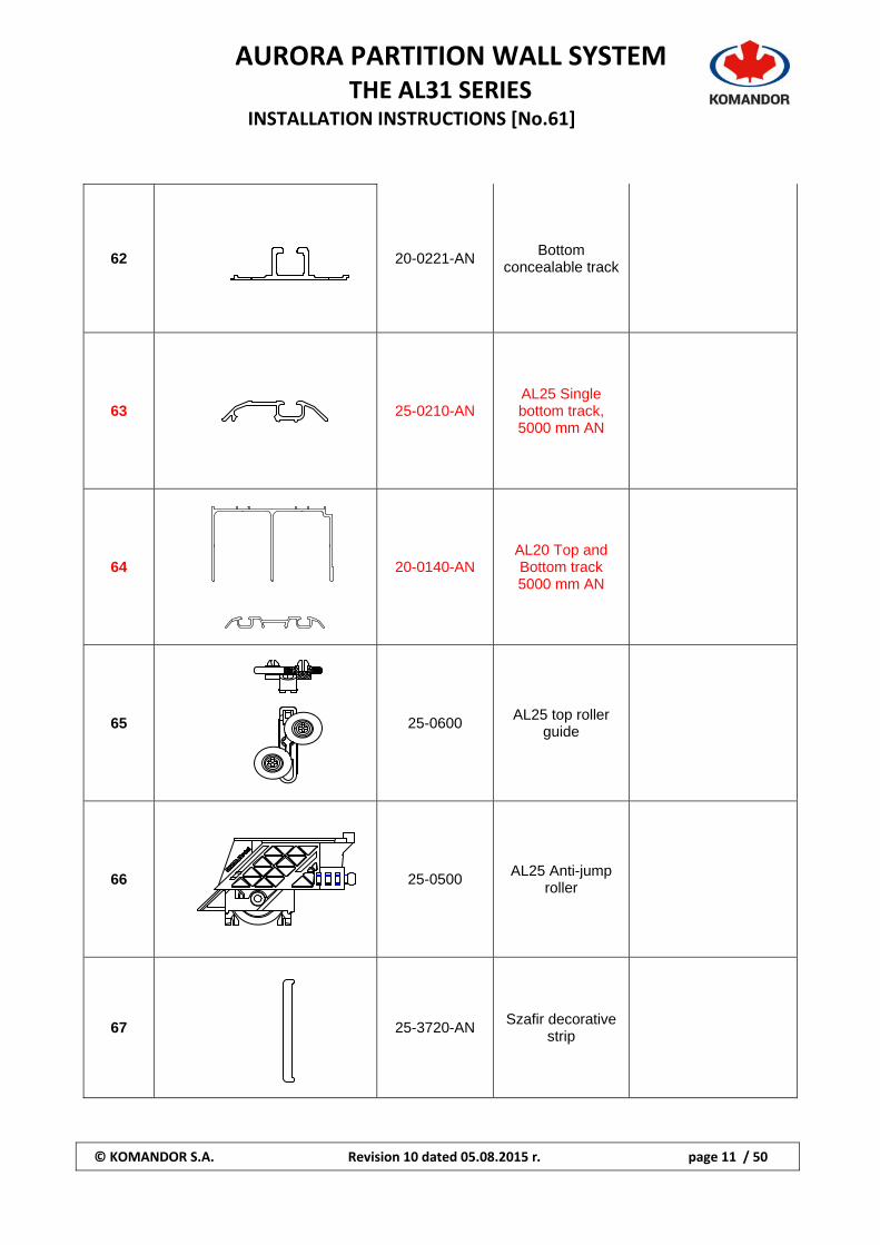
62
20-0221-AN Bottom
concealable track
63
25-0210-AN AL25 Single bottom track, 5000 mm AN
64
20-0140-AN AL20 Top and Bottom track 5000 mm AN
65
25-0600 AL25 top roller
guide
66
25-0500 AL25 Anti-jump
roller
67
25-3720-AN Szafir decorative
strip
AURORA PARTITION WALL SYSTEM
THE AL31 SERIES INSTALLATION INSTRUCTIONS [No.61]
© KOMANDOR S.A. Revision 10 dated 05.08.2015 r. page 12 / 50
68
31-1300-AN (profile
3050mm) AL31 Door profile
69
31-1320-AN
(profile 3050mm)
31-1321-AN (profile 3550mm)
AL31 Door frame
70
31-5131 AL31 Lock 2
71
31-5141 AL31 Wing hinge, Left
72
31-5142 AL31 Wing hinge, Right
73
31-5160 AL31 Lock
insert
AURORA PARTITION WALL SYSTEM
THE AL31 SERIES INSTALLATION INSTRUCTIONS [No.61]
© KOMANDOR S.A. Revision 10 dated 05.08.2015 r. page 13 / 50
74
31-5112 Lock adapter
75
31-0927-PR AL27 Gasket
6 mm, Translucent
76
59-0749 Mounting
Screw 6.3x35
77
59-0750
Countersunk head self-
forming screw M4x8
78
59-0751
Countersunk head self-
forming screw M5x10
79
59-0729
Countersunk head self-
drilling screw 3.5x13
AURORA PARTITION WALL SYSTEM
THE AL31 SERIES INSTALLATION INSTRUCTIONS [No.61]
© KOMANDOR S.A. Revision 10 dated 05.08.2015 r. page 14 / 50
Hp
Wp
80
59-0721 Mounting screw
3,5x25
81
27-1700 Top rail II
82
31-0946-AN AURORA
Rod holder connector
Hp– height panel Wp – width panel
AURORA PARTITION WALL SYSTEM
THE AL31 SERIES INSTALLATION INSTRUCTIONS [No.61]
© KOMANDOR S.A. Revision 10 dated 05.08.2015 r. page 15 / 50
General Information The partition system was designed to provide a simple wall system made of glass or panel made of modular panels that fit together and enclose a space from floor‐to‐ceiling and wall‐to‐wall. Including angled panels which can be rotated by 90°. This system allows you to implement components of the AL‐20 and AL‐25 system for sliding doors which can be integrated with, and are interchangeable with, the AL‐31 partition system. By using various insert materials such as glass and laminated panels you can create an endless variety of appearances at the will of the interior designer. The Aurora partition kits are meant for making light and movable partition‐walls in residential rooms, offices and public buildings (see table 1 according to ETAG 003, rooms of category A, B, C1 ÷ C2 and D1)* under conditions of average air temperature between +5 and +30 degrees C and the average daily and relative humidity within range from 20 to 75%.
*A – Residential rooms (spaces in buildings and houses or hospital wards; B – Office rooms, C – Meeting and conference rooms (C1 – Rooms with fixed blackboards i.e. classrooms, cafes, restaurants, canteens, reading rooms, reception areas, etc, C2‐Rooms with fixed seats, i.e. churches, theaters or cinemas, conference halls, lecture halls, meeting rooms, waiting rooms, etc.) D ‐ Commercial rooms (D1 – Rooms in general retail stores such as: rooms in department stores).
AURORA PARTITION WALL SYSTEM
THE AL31 SERIES INSTALLATION INSTRUCTIONS [No.61]
© KOMANDOR S.A. Revision 10 dated 05.08.2015 r. page 16 / 50
Wp
2
)46 ( mmWo Wp
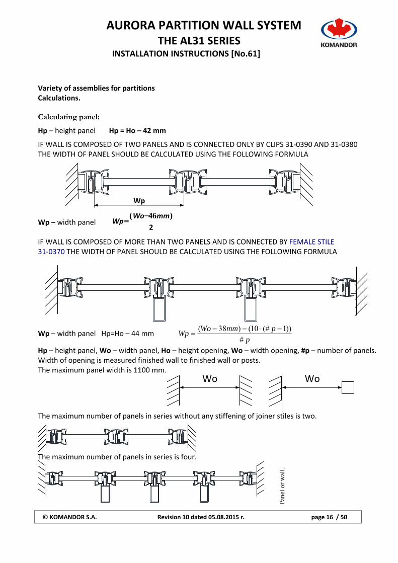
Variety of assemblies for partitions Calculations. Calculating panel:
Hp – height panel Hp = Ho – 42 mm
IF WALL IS COMPOSED OF TWO PANELS AND IS CONNECTED ONLY BY CLIPS 31‐0390 AND 31‐0380 THE WIDTH OF PANEL SHOULD BE CALCULATED USING THE FOLLOWING FORMULA
Wp – width panel IF WALL IS COMPOSED OF MORE THAN TWO PANELS AND IS CONNECTED BY FEMALE STILE 31‐0370 THE WIDTH OF PANEL SHOULD BE CALCULATED USING THE FOLLOWING FORMULA
Wp – width panel Hp=Ho – 44 mm p
pmmWoWp
#
))1(#10()38(
Hp – height panel, Wo – width panel, Ho – height opening, Wo – width opening, #p – number of panels. Width of opening is measured finished wall to finished wall or posts. The maximum panel width is 1100 mm. The maximum number of panels in series without any stiffening of joiner stiles is two.
The maximum number of panels in series is four.
Wo Wo
Pan
el o
r w
all.
AURORA PARTITION WALL SYSTEM
THE AL31 SERIES INSTALLATION INSTRUCTIONS [No.61]
© KOMANDOR S.A. Revision 10 dated 05.08.2015 r. page 17 / 50
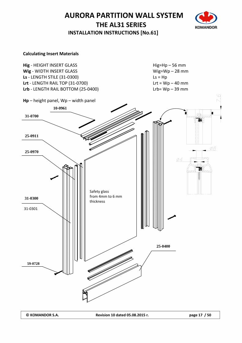
Calculating Insert Materials Hig ‐ HEIGHT INSERT GLASS Hig=Hp – 56 mm Wig ‐ WIDTH INSERT GLASS Wig=Wp – 28 mm Ls ‐ LENGTH STILE (31‐0300) Ls = Hp Lrt ‐ LENGTH RAIL TOP (31‐0700) Lrt = Wp – 40 mm Lrb ‐ LENGTH RAIL BOTTOM (25‐0400) Lrb= Wp – 39 mm Hp – height panel, Wp – width panel
Safety glass from 4mm to 6 mm thickness
10-0961
31-0700
25-0911
25-0970
31-0300
59-0728
25-0400
31‐0301
AURORA PARTITION WALL SYSTEM
THE AL31 SERIES INSTALLATION INSTRUCTIONS [No.61]
© KOMANDOR S.A. Revision 10 dated 05.08.2015 r. page 18 / 50
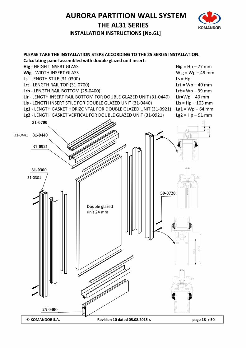
PLEASE TAKE THE INSTALLATION STEPS ACCORDING TO THE 25 SERIES INSTALLATION. Calculating panel assembled with double glazed unit insert: Hig ‐ HEIGHT INSERT GLASS Hig = Hp – 77 mm Wig ‐ WIDTH INSERT GLASS Wig = Wp – 49 mm Ls ‐ LENGTH STILE (31‐0300) Ls = Hp Lrt ‐ LENGTH RAIL TOP (31‐0700) Lrt = Wp – 40 mm Lrb ‐ LENGTH RAIL BOTTOM (25‐0400) Lrb= Wp – 39 mm Lir ‐ LENGTH INSERT RAIL BOTTOM FOR DOUBLE GLAZED UNIT (31‐0440) Lir=Wp – 40 mm Lis ‐ LENGTH INSERT STILE FOR DOUBLE GLAZED UNIT (31‐0440) Lis = Hp – 103 mm Lg1 ‐ LENGTH GASKET HORIZONTAL FOR DOUBLE GLAZED UNIT (31‐0921) Lg1 = Wp – 64 mm Lg2 ‐ LENGTH GASKET VERTICAL FOR DOUBLE GLAZED UNIT (31‐0921) Lg2 = Hp – 91 mm 25-0400
Double glazed unit 24 mm
31-0700
31-0440
31-0921
31-0300
59-0728
31‐0441
31‐0301
AURORA PARTITION WALL SYSTEM
THE AL31 SERIES INSTALLATION INSTRUCTIONS [No.61]
© KOMANDOR S.A. Revision 10 dated 05.08.2015 r. page 19 / 50
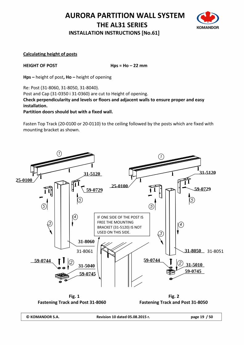
Calculating height of posts HEIGHT OF POST Hps = Ho – 22 mm Hps – height of post, Ho – height of opening
Re: Post (31‐8060, 31‐8050, 31‐8040). Post and Cap (31‐0350 i 31‐0360) are cut to Height of opening. Check perpendicularity and levels or floors and adjacent walls to ensure proper and easy installation. Partition doors should but with a fixed wall. Fasten Top Track (20‐0100 or 20‐0110) to the ceiling followed by the posts which are fixed with mounting bracket as shown. Fig. 1 Fig. 2 Fastening Track and Post 31‐8060 Fastening Track and Post 31‐8050
59-0745
25-0100 31-5120
59-0729
31-8060
31-5040 59-0744
59-0745
31-5120
25-0100 59-0729
31-8050
31-5010 59-0744
IF ONE SIDE OF THE POST IS FREE THE MOUNTING BRACKET (31‐5120) IS NOT USED ON THIS SIDE.
31‐8061 31‐8051
AURORA PARTITION WALL SYSTEM
THE AL31 SERIES INSTALLATION INSTRUCTIONS [No.61]
© KOMANDOR S.A. Revision 10 dated 05.08.2015 r. page 20 / 50
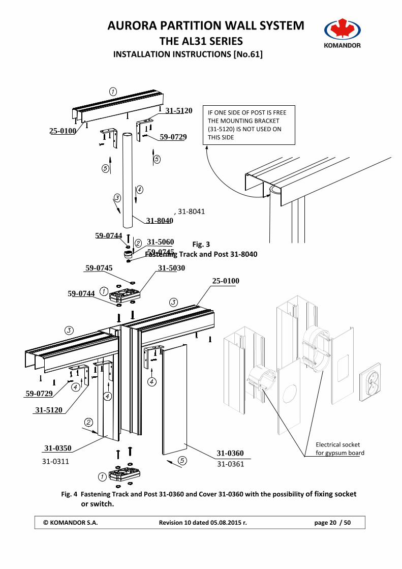
Fig. 3
Fastening Track and Post 31‐8040
Fig. 4 Fastening Track and Post 31‐0360 and Cover 31‐0360 with the possibility of fixing socket or switch.
25-0100
31-5120
59-0729
31-8040
31-506059-0745
59-0744
31-5030
31-0360
59-0745
59-0744
59-0729
31-5120
31-0350
25-0100
IF ONE SIDE OF POST IS FREE THE MOUNTING BRACKET (31‐5120) IS NOT USED ON THIS SIDE
, 31‐8041
Electrical socket for gypsum board
31‐0311 31‐0361
AURORA PARTITION WALL SYSTEM
THE AL31 SERIES INSTALLATION INSTRUCTIONS [No.61]
© KOMANDOR S.A. Revision 10 dated 05.08.2015 r. page 21 / 50
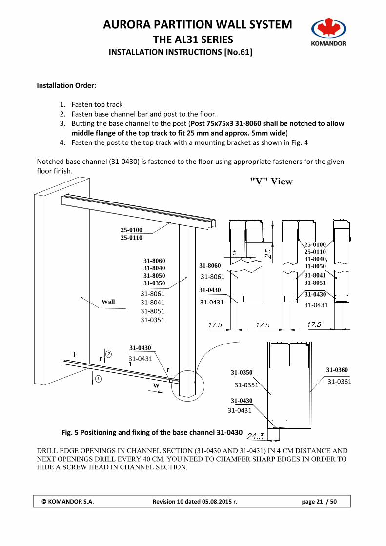
Installation Order:
1. Fasten top track 2. Fasten base channel bar and post to the floor. 3. Butting the base channel to the post (Post 75x75x3 31‐8060 shall be notched to allow
middle flange of the top track to fit 25 mm and approx. 5mm wide) 4. Fasten the post to the top track with a mounting bracket as shown in Fig. 4
Notched base channel (31‐0430) is fastened to the floor using appropriate fasteners for the given floor finish.
"V" View
Fig. 5 Positioning and fixing of the base channel 31‐0430 DRILL EDGE OPENINGS IN CHANNEL SECTION (31-0430 AND 31-0431) IN 4 CM DISTANCE AND NEXT OPENINGS DRILL EVERY 40 CM. YOU NEED TO CHAMFER SHARP EDGES IN ORDER TO HIDE A SCREW HEAD IN CHANNEL SECTION.
31-0430
Wall
31-8060 31-8040 31-8050 31-0350
25-0100 25-0110
Wi
31-8060
31-0430 31-0430
31-804131-8051
31-8040, 31-8050
25-0100 25-0110
31-0350 31-0360
31-0430
31‐8061
31‐043131‐806131‐804131‐805131‐0351
31‐0431
31‐0351
31‐0431
31‐0361
31‐0431
AURORA PARTITION WALL SYSTEM
THE AL31 SERIES INSTALLATION INSTRUCTIONS [No.61]
© KOMANDOR S.A. Revision 10 dated 05.08.2015 r. page 22 / 50
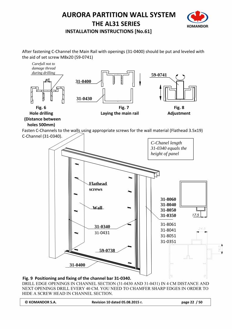
After fastening C‐Channel the Main Rail with openings (31‐0400) should be put and leveled with the aid of set screw M8x20 (59‐0741)
Fig. 6 Fig. 7 Fig. 8 Hole drilling Laying the main rail Adjustment (Distance between holes 500mm) Fasten C‐Channels to the walls using appropriate screws for the wall material (Flathead 3.5x19) C‐Channel (31‐0340).
Fig. 9 Positioning and fixing of the channel bar 31‐0340. DRILL EDGE OPENINGS IN CHANNEL SECTION (31-0430 AND 31-0431) IN 4 CM DISTANCE AND NEXT OPENINGS DRILL EVERY 40 CM. YOU NEED TO CHAMFER SHARP EDGES IN ORDER TO HIDE A SCREW HEAD IN CHANNEL SECTION.
Carefull not to damage thread during drilling
31-0430
31-0400
59-0741
C-Chanel length 31-0340 equals the height of panel
31-8060 31-8040 31-8050 31-0350
31‐8061 31‐8041 31‐8051 31‐0351
Flathead screws
31-0340
59-0738
Wall
31-0400
31‐0431
AURORA PARTITION WALL SYSTEM
THE AL31 SERIES INSTALLATION INSTRUCTIONS [No.61]
© KOMANDOR S.A. Revision 10 dated 05.08.2015 r. page 23 / 50
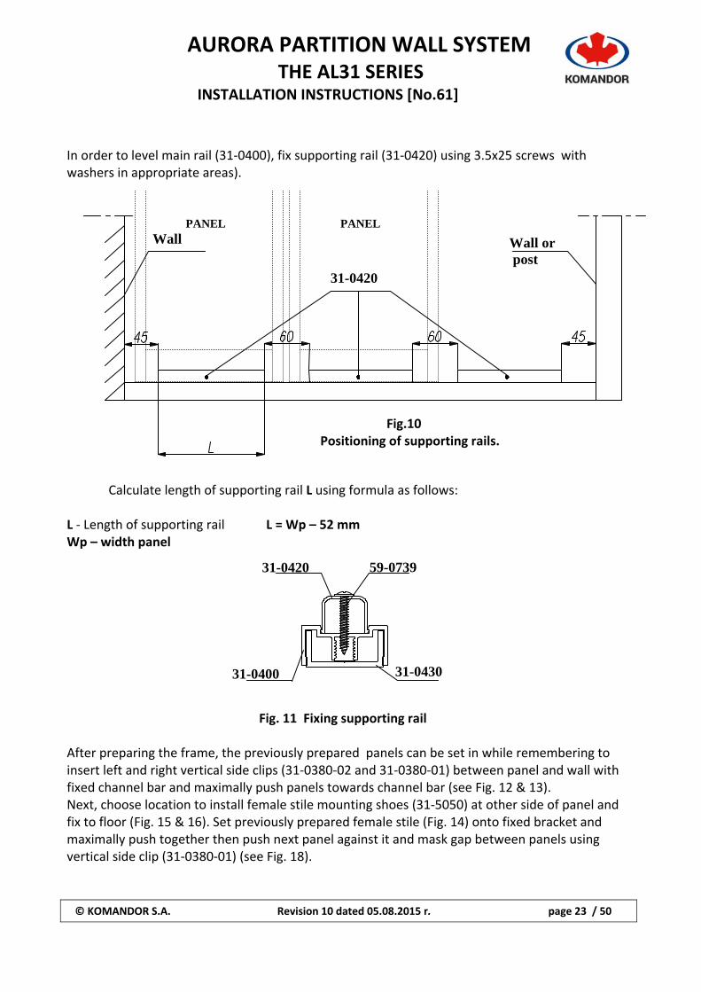
In order to level main rail (31‐0400), fix supporting rail (31‐0420) using 3.5x25 screws with washers in appropriate areas).
Fig.10 Positioning of supporting rails.
Calculate length of supporting rail L using formula as follows:
L ‐ Length of supporting rail L = Wp – 52 mm Wp – width panel
Fig. 11 Fixing supporting rail After preparing the frame, the previously prepared panels can be set in while remembering to insert left and right vertical side clips (31‐0380‐02 and 31‐0380‐01) between panel and wall with fixed channel bar and maximally push panels towards channel bar (see Fig. 12 & 13). Next, choose location to install female stile mounting shoes (31‐5050) at other side of panel and fix to floor (Fig. 15 & 16). Set previously prepared female stile (Fig. 14) onto fixed bracket and maximally push together then push next panel against it and mask gap between panels using vertical side clip (31‐0380‐01) (see Fig. 18).
59-0739
31-043031-0400
31-0420
31-0420
Wall Wall or post
PANEL PANEL
AURORA PARTITION WALL SYSTEM
THE AL31 SERIES INSTALLATION INSTRUCTIONS [No.61]
© KOMANDOR S.A. Revision 10 dated 05.08.2015 r. page 24 / 50
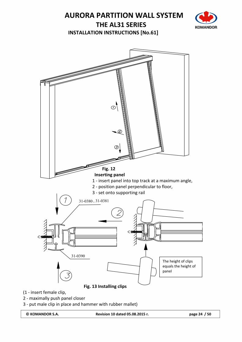
Fig. 12 Inserting panel 1 ‐ insert panel into top track at a maximum angle, 2 ‐ position panel perpendicular to floor, 3 ‐ set onto supporting rail
Fig. 13 Installing clips (1 ‐ insert female clip, 2 ‐ maximally push panel closer 3 ‐ put male clip in place and hammer with rubber mallet)
31-0380
31-0390 The height of clips equals the height of panel
, 31-0381
AURORA PARTITION WALL SYSTEM
THE AL31 SERIES INSTALLATION INSTRUCTIONS [No.61]
© KOMANDOR S.A. Revision 10 dated 05.08.2015 r. page 25 / 50
b a
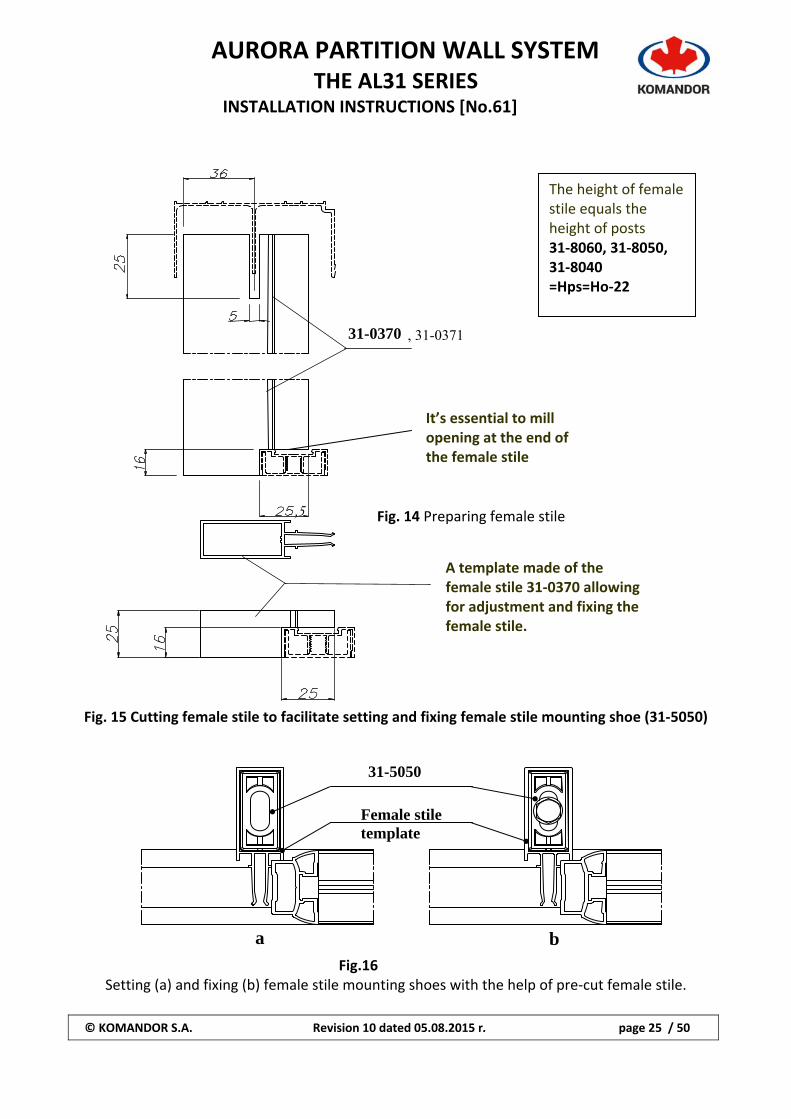
Fig. 14 Preparing female stile Fig. 15 Cutting female stile to facilitate setting and fixing female stile mounting shoe (31‐5050)
Fig.16
Setting (a) and fixing (b) female stile mounting shoes with the help of pre‐cut female stile.
31-5050
Female stile template
The height of female stile equals the height of posts 31‐8060, 31‐8050, 31‐8040 =Hps=Ho‐22
A template made of the female stile 31‐0370 allowing for adjustment and fixing the female stile.
31-0370
It’s essential to mill opening at the end of the female stile
,5
, 31-0371
AURORA PARTITION WALL SYSTEM
THE AL31 SERIES INSTALLATION INSTRUCTIONS [No.61]
© KOMANDOR S.A. Revision 10 dated 05.08.2015 r. page 26 / 50
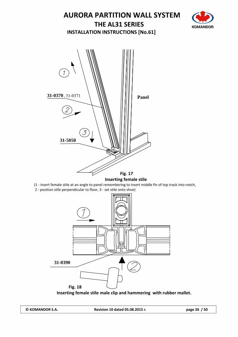
Fig. 17 Inserting female stile
(1 ‐ insert female stile at an angle to panel remembering to insert middle fin of top track into notch, 2 ‐ position stile perpendicular to floor, 3 ‐ set stile onto shoe)
Fig. 18 Inserting female stile male clip and hammering with rubber mallet.
31-0370
31-5050
Panel
31-0390
, 31-0371
AURORA PARTITION WALL SYSTEM
THE AL31 SERIES INSTALLATION INSTRUCTIONS [No.61]
© KOMANDOR S.A. Revision 10 dated 05.08.2015 r. page 27 / 50
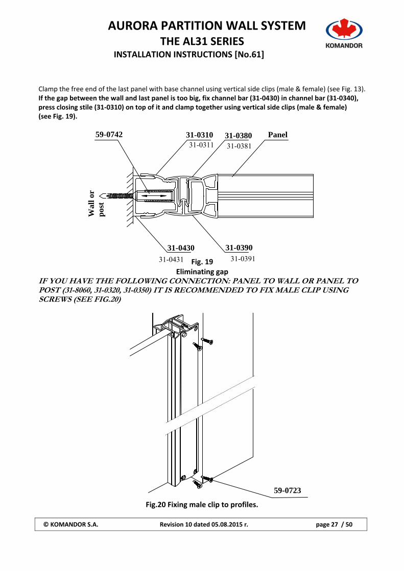
Clamp the free end of the last panel with base channel using vertical side clips (male & female) (see Fig. 13). If the gap between the wall and last panel is too big, fix channel bar (31‐0430) in channel bar (31‐0340), press closing stile (31‐0310) on top of it and clamp together using vertical side clips (male & female) (see Fig. 19).
Fig. 19
Eliminating gap IF YOU HAVE THE FOLLOWING CONNECTION: PANEL TO WALL OR PANEL TO POST (31-8060, 31-0320, 31-0350) IT IS RECOMMENDED TO FIX MALE CLIP USING SCREWS (SEE FIG.20)
Fig.20 Fixing male clip to profiles.
Wal
l or
pos
t
59-0742 31-0310 31-0380 Panel
31-0430 31-0390
59-0723
31-0311 31-0381
31-0431 31-0391
AURORA PARTITION WALL SYSTEM
THE AL31 SERIES INSTALLATION INSTRUCTIONS [No.61]
© KOMANDOR S.A. Revision 10 dated 05.08.2015 r. page 28 / 50
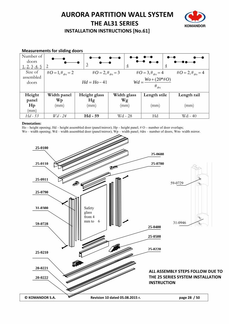
Measurements for sliding doors Number of
doors 1, 2, 3 ,4, 5 2 3 4 4
Size of assembled
doors
2#,1# drsO 3#,2# drsO 4#,3# drsO 4#,2# drsO
41 HoHd drs
OWoWd
#
)*#20(
Height panel Hp
(mm)
Width panel Wp
(mm)
Height glass Hg
(mm)
Width glass Wg
(mm)
Length stile
(mm)
Length rail
(mm)
Hd - 53 Wd - 24 Hd - 59 Wd - 28 Hd Wd - 40
Denotation: Ho – height opening; Hd – height assembled door (panel/mirror); Hp – height panel; # O – number of door overlaps; Wo – width opening; Wd – width assembled door (panel/mirror); Wp – width panel; #drs – number of doors, Wm- width mirror.
Safety glass from 4 mm to 6
25-0600
25-0700
25-0400
25-0500
25-0220
20-0222
20-0221
25-0210
59-0728
31-0300
25-0790
25-0911
25-0110
25-0100
ALL ASSEMBLY STEPS FOLLOW DUE TO THE 25 SERIES SYSTEM INSTALLATION INSTRUCTION
59-0729
31-0946
AURORA PARTITION WALL SYSTEM
THE AL31 SERIES INSTALLATION INSTRUCTIONS [No.61]
© KOMANDOR S.A. Revision 10 dated 05.08.2015 r. page 29 / 50
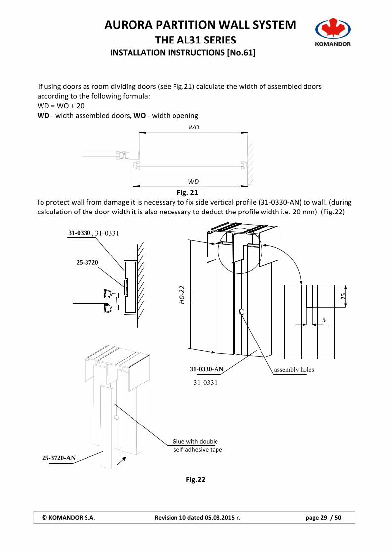
If using doors as room dividing doors (see Fig.21) calculate the width of assembled doors according to the following formula: WD = WO + 20 WD ‐ width assembled doors, WO ‐ width opening
Fig. 21 To protect wall from damage it is necessary to fix side vertical profile (31‐0330‐AN) to wall. (during calculation of the door width it is also necessary to deduct the profile width i.e. 20 mm) (Fig.22)
Fig.22
31-0330
25-3720
25-3720-AN
31-0330-AN
Glue with double self‐adhesive tape
WO
WDW
O-2
2
25
5
assembly holes
HO‐22
, 31-0331
31-0331
AURORA PARTITION WALL SYSTEM
THE AL31 SERIES INSTALLATION INSTRUCTIONS [No.61]
© KOMANDOR S.A. Revision 10 dated 05.08.2015 r. page 30 / 50
31-0350 31-0360
31-806031-0320
59-0740
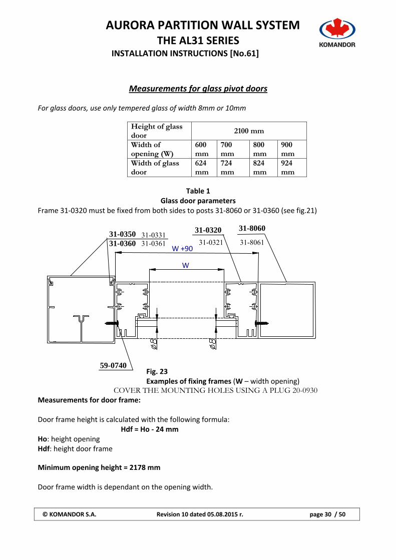
Measurements for glass pivot doors For glass doors, use only tempered glass of width 8mm or 10mm
Height of glass door
2100 mm
Width of opening (W)
600 mm
700 mm
800 mm
900 mm
Width of glass door
624 mm
724 mm
824 mm
924 mm
Table 1
Glass door parameters Frame 31‐0320 must be fixed from both sides to posts 31‐8060 or 31‐0360 (see fig.21)
Fig. 23 Examples of fixing frames (W – width opening)
COVER THE MOUNTING HOLES USING A PLUG 20-0930 Measurements for door frame: Door frame height is calculated with the following formula: Hdf = Ho ‐ 24 mm Ho: height opening Hdf: height door frame Minimum opening height = 2178 mm Door frame width is dependant on the opening width.
+ W +90
W
31-033131-0361 31-0321 31-8061
AURORA PARTITION WALL SYSTEM
THE AL31 SERIES INSTALLATION INSTRUCTIONS [No.61]
© KOMANDOR S.A. Revision 10 dated 05.08.2015 r. page 31 / 50
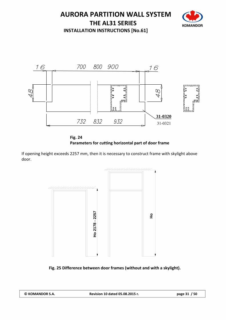
Fig. 24 Parameters for cutting horizontal part of door frame
If opening height exceeds 2257 mm, then it is necessary to construct frame with skylight above door.
Fig. 25 Difference between door frames (without and with a skylight).
31-0320
Ho
Ho
217
8 -
2257
31-0321
AURORA PARTITION WALL SYSTEM
THE AL31 SERIES INSTALLATION INSTRUCTIONS [No.61]
© KOMANDOR S.A. Revision 10 dated 05.08.2015 r. page 32 / 50
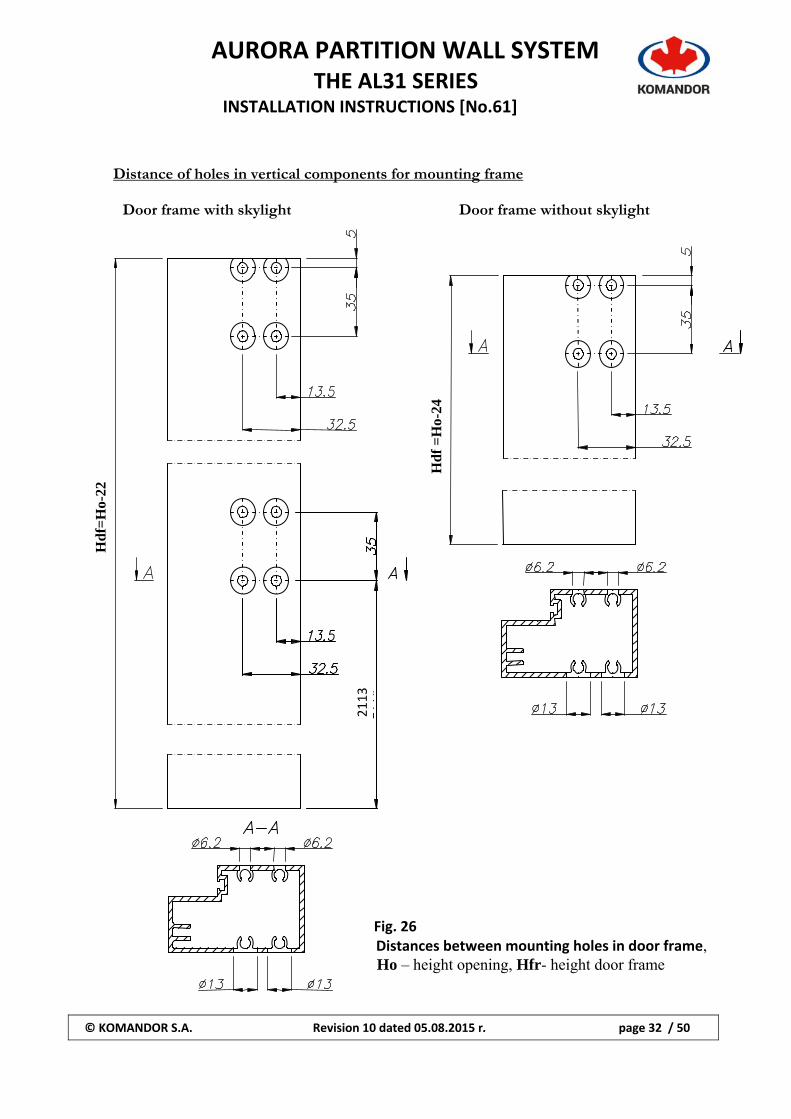
Distance of holes in vertical components for mounting frame
Door frame with skylight Door frame without skylight
Fig. 26 Distances between mounting holes in door frame, Ho – height opening, Hfr- height door frame
Hd
f =
Ho-
24
Hd
f=H
o-22
2118
2113
AURORA PARTITION WALL SYSTEM
THE AL31 SERIES INSTALLATION INSTRUCTIONS [No.61]
© KOMANDOR S.A. Revision 10 dated 05.08.2015 r. page 33 / 50
59-0750
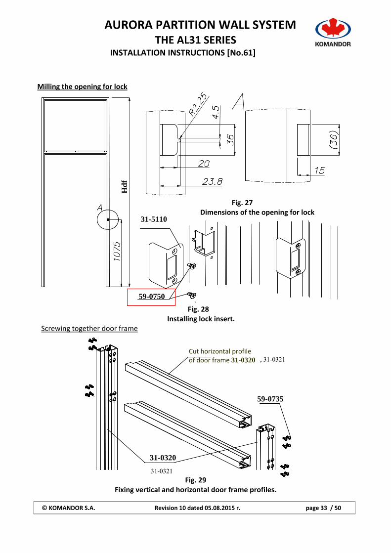
Milling the opening for lock
Fig. 27 Dimensions of the opening for lock
. Fig. 28
Installing lock insert. Screwing together door frame
Fig. 29
Fixing vertical and horizontal door frame profiles.
Hd
f
Cut horizontal profile of door frame 31-0320
31-0320
59-0735
31-5110
, 31-0321
31-0321
AURORA PARTITION WALL SYSTEM
THE AL31 SERIES INSTALLATION INSTRUCTIONS [No.61]
© KOMANDOR S.A. Revision 10 dated 05.08.2015 r. page 34 / 50
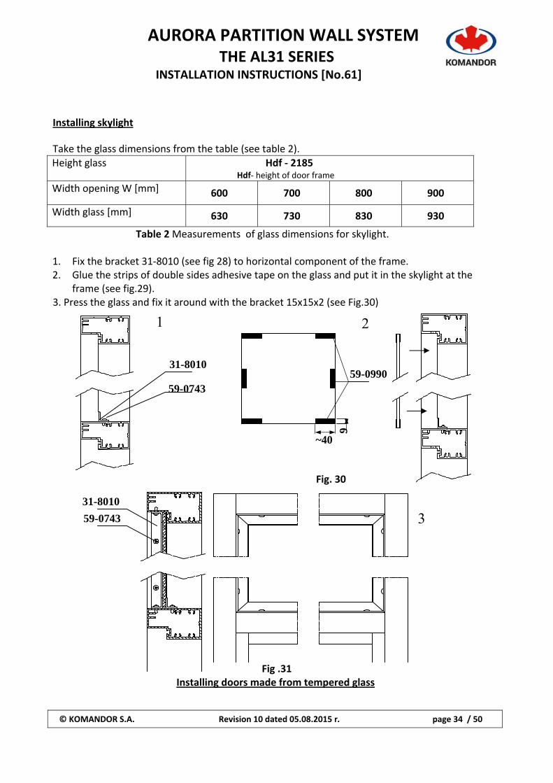
Installing skylight Take the glass dimensions from the table (see table 2).
Height glass Hdf ‐ 2185 Hdf‐ height of door frame
Width opening W [mm] 600 700 800 900
Width glass [mm] 630 730 830 930
Table 2 Measurements of glass dimensions for skylight. 1. Fix the bracket 31‐8010 (see fig 28) to horizontal component of the frame. 2. Glue the strips of double sides adhesive tape on the glass and put it in the skylight at the
frame (see fig.29). 3. Press the glass and fix it around with the bracket 15x15x2 (see Fig.30)
Fig. 30
Fig .31 Installing doors made from tempered glass
31-8010
59-0743
31-8010
59-0743
9
~40
59-0990
1 2
3
AURORA PARTITION WALL SYSTEM
THE AL31 SERIES INSTALLATION INSTRUCTIONS [No.61]
© KOMANDOR S.A. Revision 10 dated 05.08.2015 r. page 35 / 50
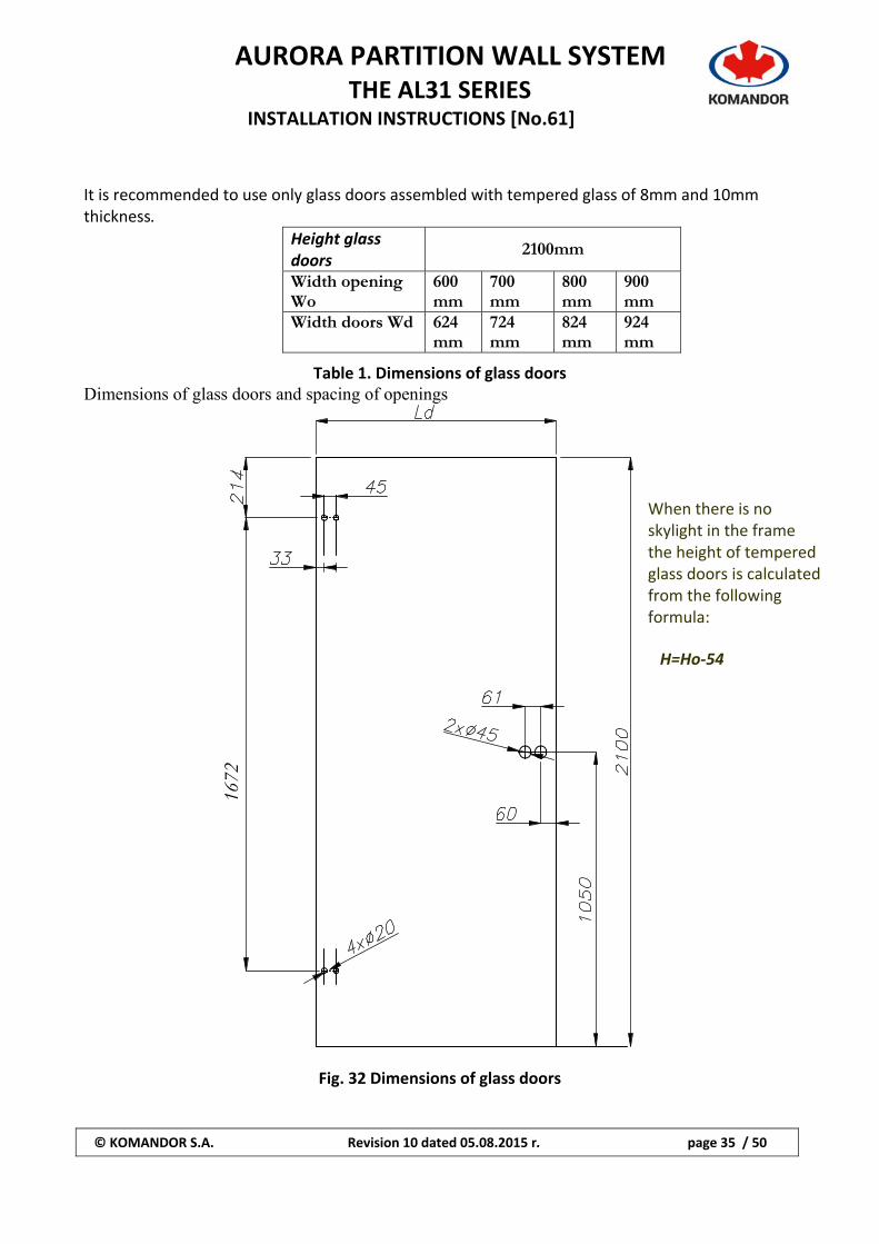
It is recommended to use only glass doors assembled with tempered glass of 8mm and 10mm thickness.
Height glass doors
2100mm
Width opening Wo
600 mm
700 mm
800 mm
900 mm
Width doors Wd 624 mm
724 mm
824 mm
924 mm
Table 1. Dimensions of glass doors Dimensions of glass doors and spacing of openings
Fig. 32 Dimensions of glass doors
1672
When there is no skylight in the frame the height of tempered glass doors is calculated from the following formula: H=Ho‐54
AURORA PARTITION WALL SYSTEM
THE AL31 SERIES INSTALLATION INSTRUCTIONS [No.61]
© KOMANDOR S.A. Revision 10 dated 05.08.2015 r. page 36 / 50
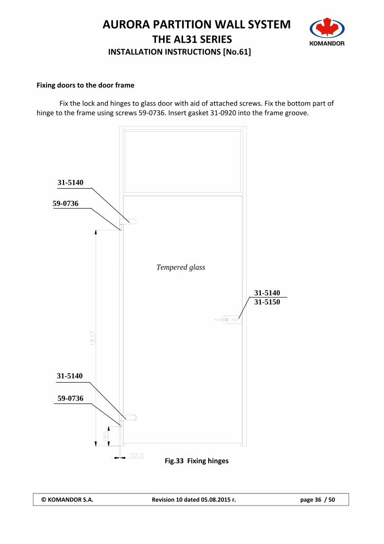
Fixing doors to the door frame
Fix the lock and hinges to glass door with aid of attached screws. Fix the bottom part of hinge to the frame using screws 59‐0736. Insert gasket 31‐0920 into the frame groove.
Fig.33 Fixing hinges
59-0736
59-0736
31-5140
31-5140
Tempered glass
31-5140 31-5150
AURORA PARTITION WALL SYSTEM
THE AL31 SERIES INSTALLATION INSTRUCTIONS [No.61]
© KOMANDOR S.A. Revision 10 dated 05.08.2015 r. page 37 / 50
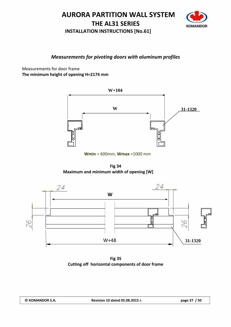
Measurements for pivoting doors with aluminum profiles
Measurements for door frame The minimum height of opening H=2174 mm
Fig 34 Maximum and minimum width of opening [W]
Fig 35 Cutting off horizontal components of door frame
Wmin = 600mm, Wmax =1000 mm
W+104
W 31-1320
W
W+48 31-1320
AURORA PARTITION WALL SYSTEM
THE AL31 SERIES INSTALLATION INSTRUCTIONS [No.61]
© KOMANDOR S.A. Revision 10 dated 05.08.2015 r. page 38 / 50
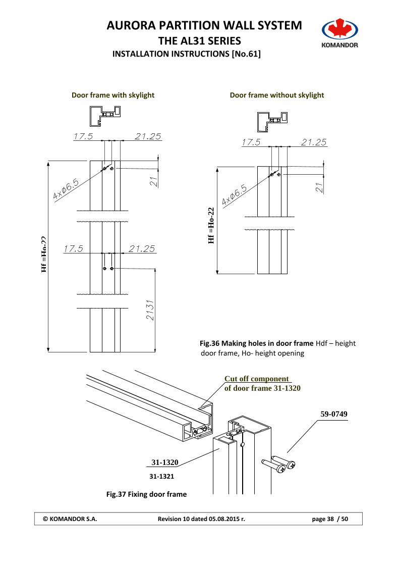
Fig.36 Making holes in door frame Hdf – height door frame, Ho‐ height opening
Fig.37 Fixing door frame
59-0749
Cut off component of door frame 31-1320
31-1320
Hf
=H
o-22 H
f =
Ho-
22
Door frame without skylight Door frame with skylight
31‐1321
AURORA PARTITION WALL SYSTEM
THE AL31 SERIES INSTALLATION INSTRUCTIONS [No.61]
© KOMANDOR S.A. Revision 10 dated 05.08.2015 r. page 39 / 50
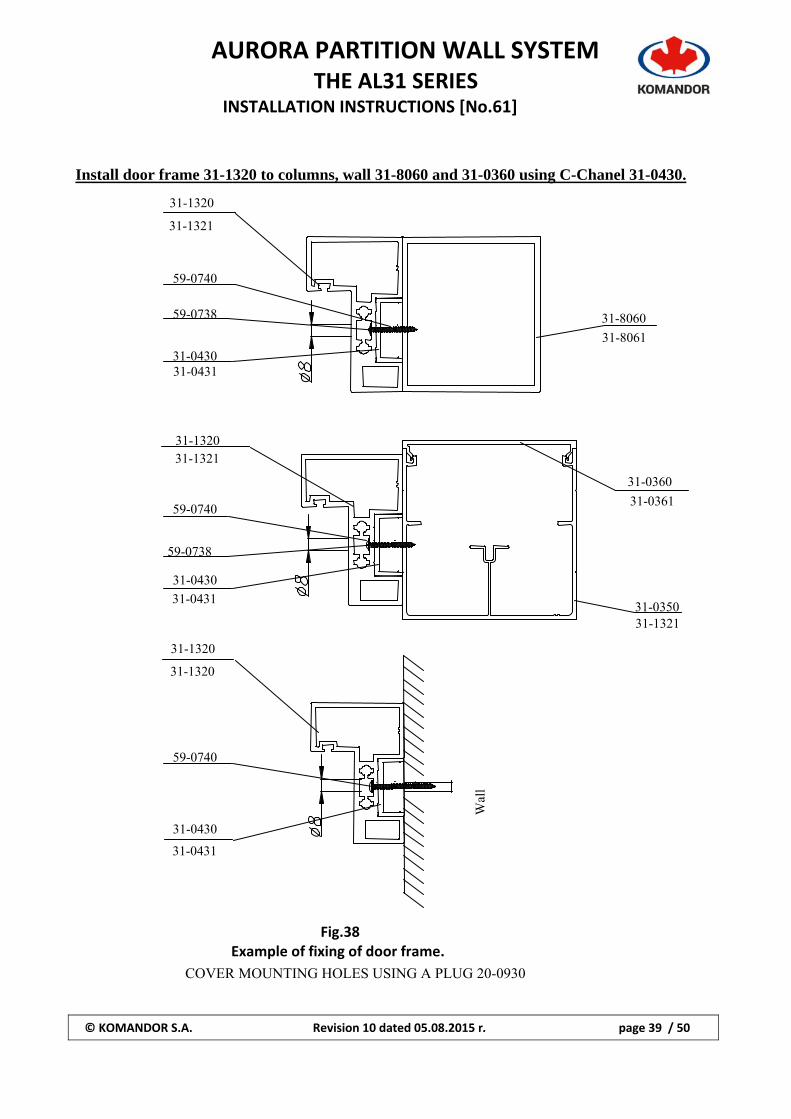
Install door frame 31-1320 to columns, wall 31-8060 and 31-0360 using C-Chanel 31-0430.
Fig.38
Example of fixing of door frame.
COVER MOUNTING HOLES USING A PLUG 20-0930
Wal
l
31-1320
31-0430
59-0740
31-1320
31-0431
31-1320
31-0430
31-0360
31-0350
59-0738
59-0740
31-0431
31-1321
31-1321
31-0361
31-1320
31-8060
31-0430
59-0738
59-0740
31-0431
31-1321
31-8061
AURORA PARTITION WALL SYSTEM
THE AL31 SERIES INSTALLATION INSTRUCTIONS [No.61]
© KOMANDOR S.A. Revision 10 dated 05.08.2015 r. page 40 / 50
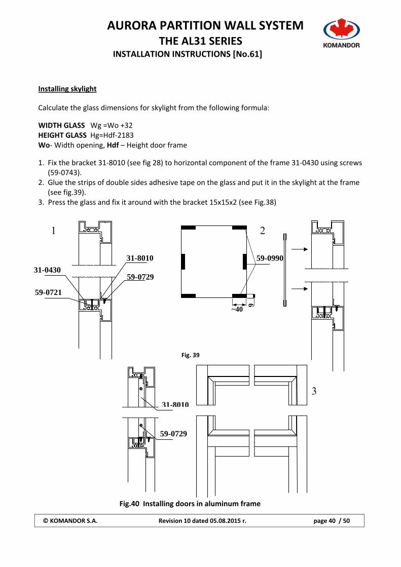
Installing skylight Calculate the glass dimensions for skylight from the following formula: WIDTH GLASS Wg =Wo +32 HEIGHT GLASS Hg=Hdf‐2183 Wo‐ Width opening, Hdf – Height door frame 1. Fix the bracket 31‐8010 (see fig 28) to horizontal component of the frame 31‐0430 using screws
(59‐0743). 2. Glue the strips of double sides adhesive tape on the glass and put it in the skylight at the frame
(see fig.39). 3. Press the glass and fix it around with the bracket 15x15x2 (see Fig.38)
Fig. 39
Fig.40 Installing doors in aluminum frame
31-0430
59-0721
31-8010
59-0729
9
~40
59-0990
1 2
3 31-8010
59-0729
AURORA PARTITION WALL SYSTEM
THE AL31 SERIES INSTALLATION INSTRUCTIONS [No.61]
© KOMANDOR S.A. Revision 10 dated 05.08.2015 r. page 41 / 50
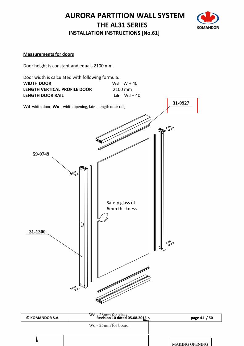
Measurements for doors Door height is constant and equals 2100 mm. Door width is calculated with following formula: WIDTH DOOR Wd = W + 40 LENGTH VERTICAL PROFILE DOOR 2100 mm LENGTH DOOR RAIL Ldr = Wd – 40
Wd‐ width door, Wo – width opening, Ldr – length door rail,
31-0927
Safety glass of 6mm thickness
59-0749
31-1300
Wd - 28mm for glass Wd - 25mm for board
MAKING OPENING
AURORA PARTITION WALL SYSTEM
THE AL31 SERIES INSTALLATION INSTRUCTIONS [No.61]
© KOMANDOR S.A. Revision 10 dated 05.08.2015 r. page 42 / 50
Fig.41 Dimensions of glass in doors assembled with aluminum frame, Wd – width door
Making opening for lock.
AURORA PARTITION WALL SYSTEM
THE AL31 SERIES INSTALLATION INSTRUCTIONS [No.61]
© KOMANDOR S.A. Revision 10 dated 05.08.2015 r. page 43 / 50
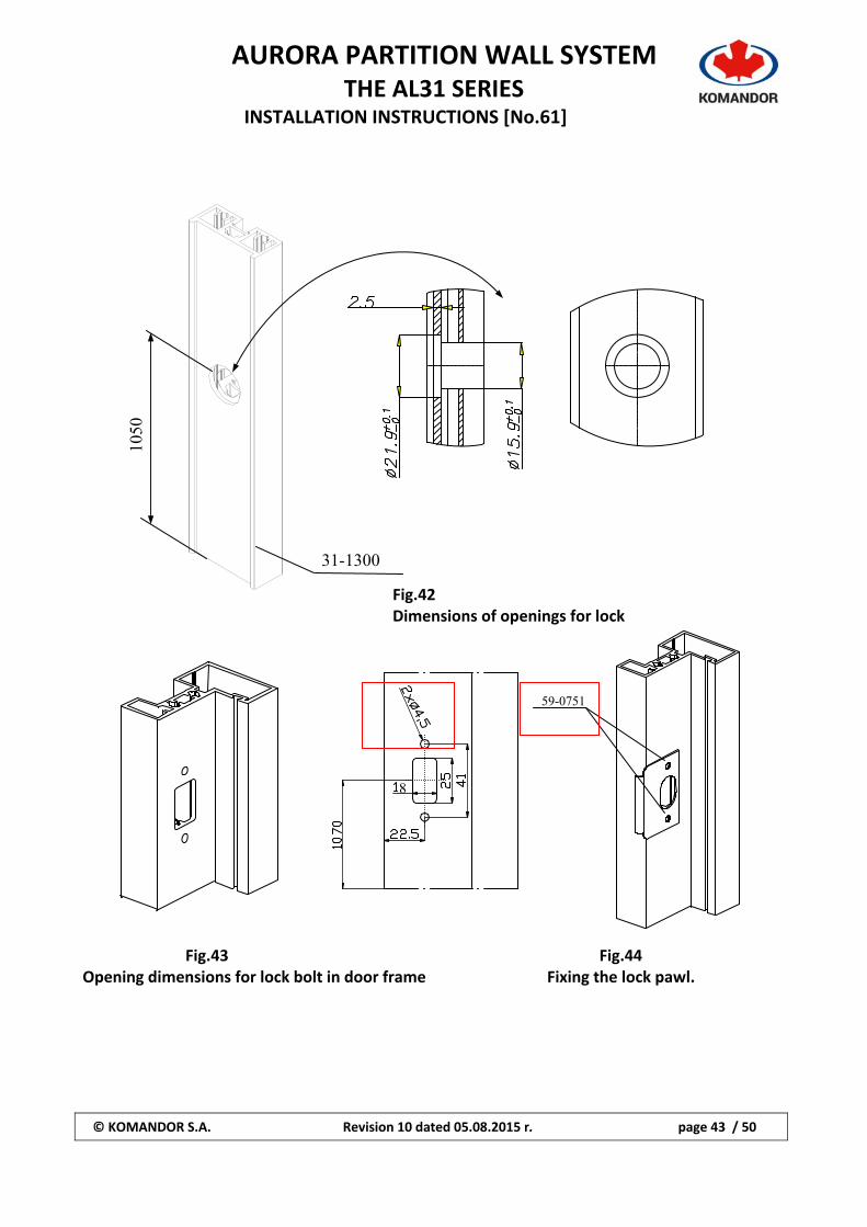
Fig.42 Dimensions of openings for lock
Fig.43 Fig.44 Opening dimensions for lock bolt in door frame Fixing the lock pawl.
1050
31-1300
8
59-0751
AURORA PARTITION WALL SYSTEM
THE AL31 SERIES INSTALLATION INSTRUCTIONS [No.61]
© KOMANDOR S.A. Revision 10 dated 05.08.2015 r. page 44 / 50
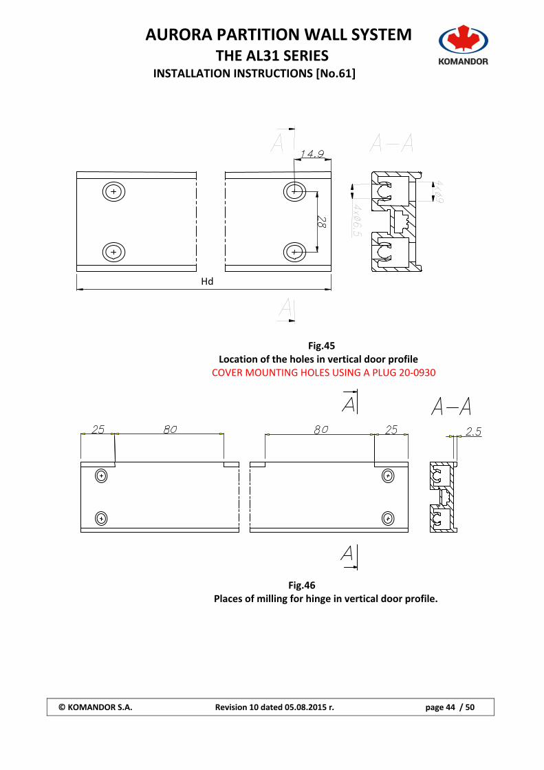
Fig.45 Location of the holes in vertical door profile
COVER MOUNTING HOLES USING A PLUG 20‐0930
Fig.46 Places of milling for hinge in vertical door profile.
Hd
AURORA PARTITION WALL SYSTEM
THE AL31 SERIES INSTALLATION INSTRUCTIONS [No.61]
© KOMANDOR S.A. Revision 10 dated 05.08.2015 r. page 45 / 50
`
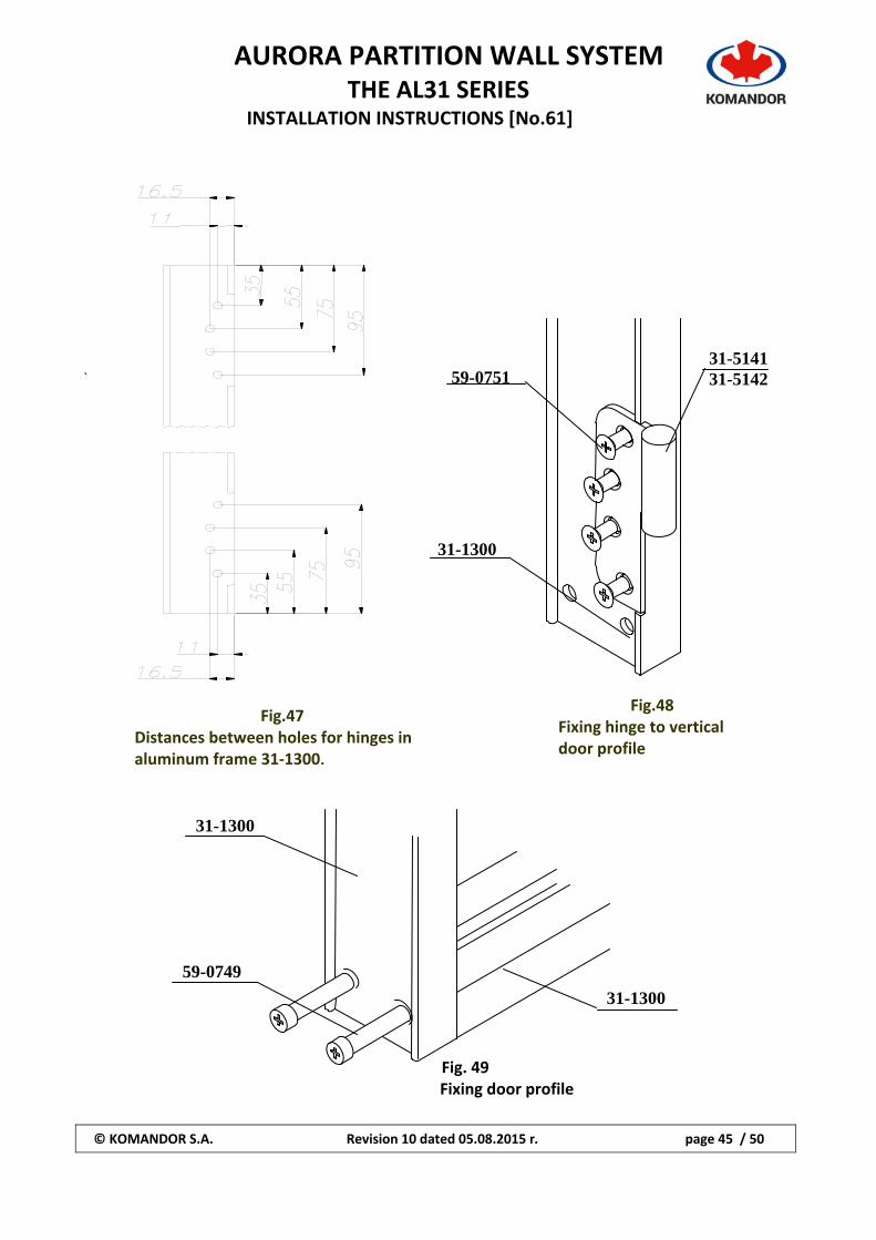
Fig. 49 Fixing door profile
59-0751
31-1300
31-5141 31-5142
31-1300
59-0749
31-1300
Fig.47 Distances between holes for hinges in aluminum frame 31‐1300.
Fig.48 Fixing hinge to vertical door profile
AURORA PARTITION WALL SYSTEM
THE AL31 SERIES INSTALLATION INSTRUCTIONS [No.61]
© KOMANDOR S.A. Revision 10 dated 05.08.2015 r. page 46 / 50
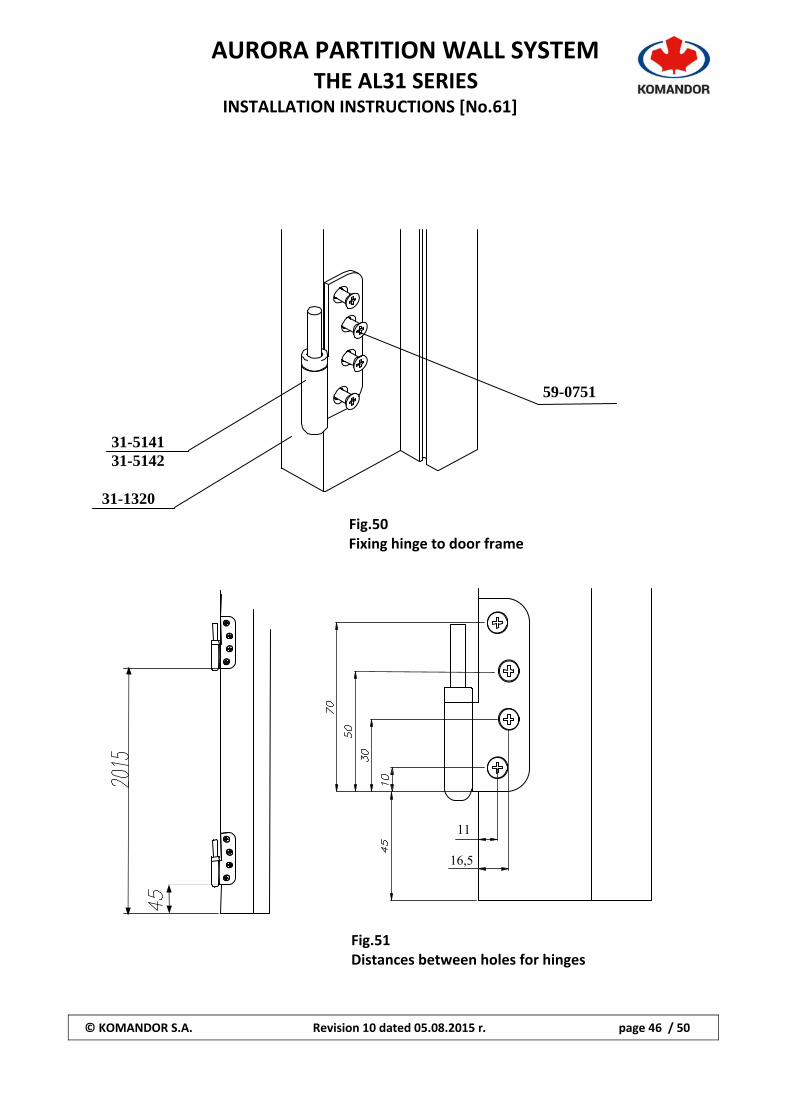
Fig.50 Fixing hinge to door frame
Fig.51 Distances between holes for hinges
31-1320
31-5141 31-5142
59-0751
11
16,5
AURORA PARTITION WALL SYSTEM
THE AL31 SERIES INSTALLATION INSTRUCTIONS [No.61]
© KOMANDOR S.A. Revision 10 dated 05.08.2015 r. page 47 / 50
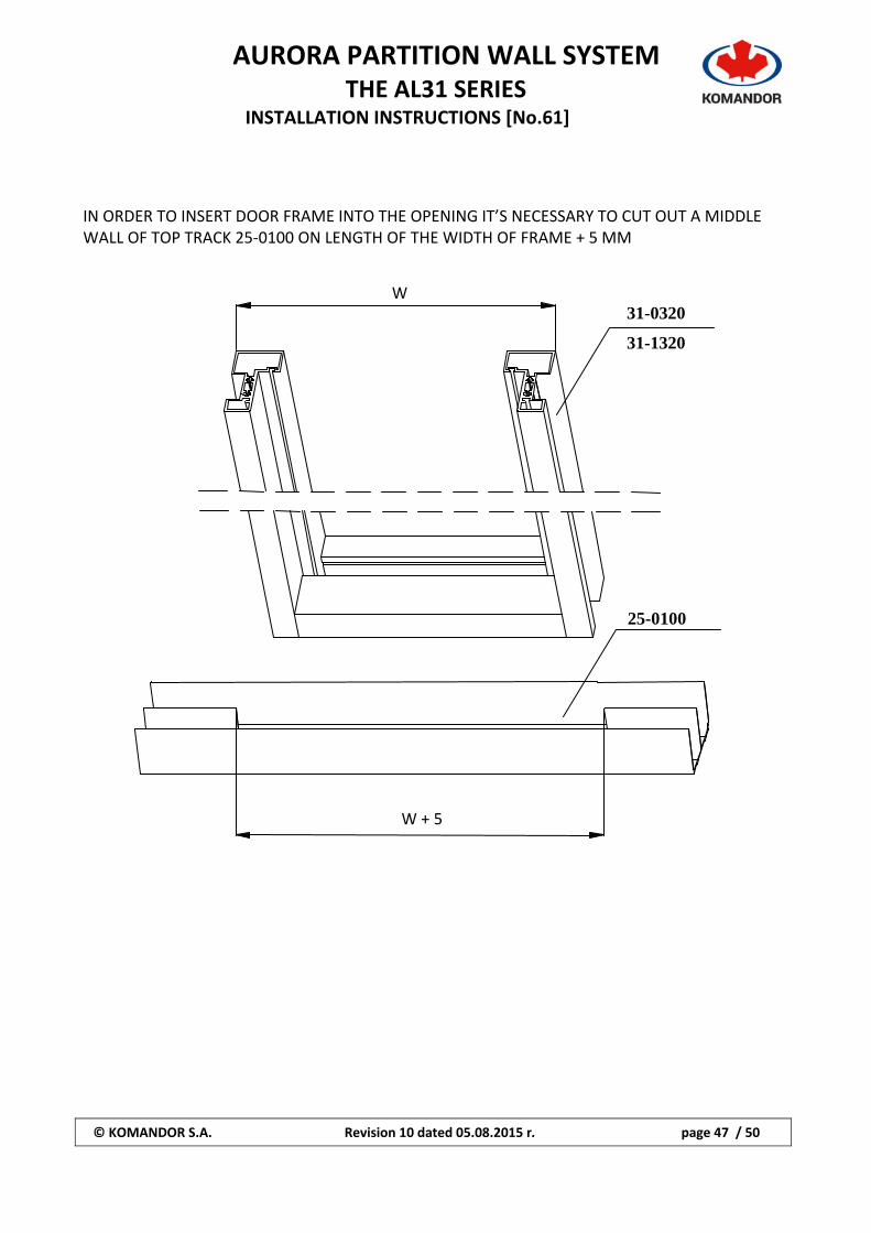
IN ORDER TO INSERT DOOR FRAME INTO THE OPENING IT’S NECESSARY TO CUT OUT A MIDDLE WALL OF TOP TRACK 25‐0100 ON LENGTH OF THE WIDTH OF FRAME + 5 MM
31-0320
31-1320
25-0100
W
W + 5
AURORA PARTITION WALL SYSTEM
THE AL31 SERIES INSTALLATION INSTRUCTIONS [No.61]
© KOMANDOR S.A. Revision 10 dated 05.08.2015 r. page 48 / 50
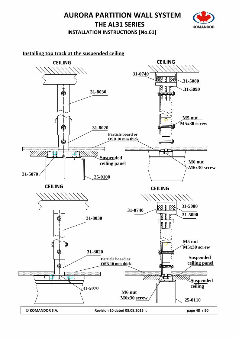
Installing top track at the suspended ceiling
CEILING
31-8030
31-8020
31-5070 25-0100
Suspended ceiling panel
M5 nut M5x30 screw
31-5080
31-5090
M6 nut M6x30 screw
31-0740
Particle board or OSB 10 mm thick
31-8030
31-8020
31-5070
SUFIT
Suspended ceiling
31-0740 31-5080
31-5090
M5 nut M5x30 screw
Suspended ceiling panel
CEILING
CEILING CEILING
Particle board or OSB 10 mm thick
M6 nut M6x30 screw 25-0110
AURORA PARTITION WALL SYSTEM
THE AL31 SERIES INSTALLATION INSTRUCTIONS [No.61]
© KOMANDOR S.A. Revision 10 dated 05.08.2015 r. page 49 / 50
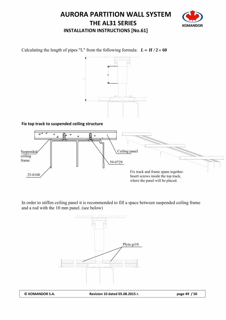
Calculating the length of pipes "L" from the following formula: 602/ HL Fix top track to suspended ceiling structure In order to stiffen ceiling panel it is recommended to fill a space between suspended ceiling frame and a rod with the 10 mm panel. (see below)
L
Ceiling panel
59-0729
25-0100
Suspended ceiling frame
Fix track and frame spans together. Insert screws inside the top track, where the panel will be placed.
Płyta gr10
AURORA PARTITION WALL SYSTEM
THE AL31 SERIES INSTALLATION INSTRUCTIONS [No.61]
© KOMANDOR S.A. Revision 10 dated 05.08.2015 r. page 50 / 50
LIST OF CONTENTS 1. Parts list page 1 – 14 2. Calculating and Installing walls page 14‐26 3. Calculating sliding doors page 27 4. Calculating and assembling doors with tempered glass page 28 – 34 5. Calculating and assembling doors with aluminum profile page 35 – 46 6. Installing top track to the suspending ceiling page 47 – 50


![Installation of partition wall systems 712[06].S1](https://img.pdfslide.net/doc/110x75/620730ad49d709492c2ed15b/installation-of-partition-wall-systems-71206s1.jpg)
![Installation of partition wall systems 712[06].S1.02](https://img.pdfslide.net/doc/110x75/5880affc1a28ab74298c6016/installation-of-partition-wall-systems-71206s102.jpg)