Embed Size (px)
Citation preview

Queensland
AUS-SPEC #1
DEVELOPMENT SPECIFICATION SERIES
DESIGN
BURNETT SHIRE COUNCIL
Supplied Version : 9/08/2004


AUS-SPEC-1\QLD-list.doc
QUEENSLAND AUS-SPEC #1 DEVELOPMENT SPECIFICATION SERIES
DESIGN
Specification No. Specification Title
DQS Quality Assurance Requirements for Design D1 Geometric Road Design (Urban and Rural) D2 Pavement Design D3 Structures/Bridge Design D4 Subsurface Drainage Design D5 Stormwater Drainage Design D6 Site Regrading D7 Erosion Control and Stormwater Management D8 Waterfront Development D9 Cycleway and Pathway Design D10 Bushfire Protection D11 Water Reticulation D12 Sewerage System

Queensland
AUS-SPEC #1
DEVELOPMENT SPECIFICATION SERIES
DESIGN
Under License – Burnett Shire versions of
the specifications in “Word Document Format”
are available on request for
Developments within the Burnett Shire


Contract No. QUALITY ASSURANCE FOR DESIGN
© IPWEA 2004 AUS-SPEC-1\QLD-DQS BURNETT SHIRE COUNCIL
QUEENSLAND
DEVELOPMENT DESIGN SPECIFICATION
DQS
QUALITY ASSURANCE
REQUIREMENTS FOR DESIGN


Contract No. CONTROL OF EROSION AND SEDIMENTATION
© IPWEA 2004 AUS-SPEC-1\QLD-C211 BURNETT SHIRE COUNCIL
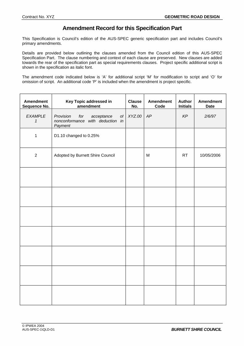
Amendment Record for this Specification Part
This Specification is Council’s edition of the AUS-SPEC generic specification part and includes Council’s primary amendments.
Details are provided below outlining the clauses amended from the Council edition of this AUS-SPEC Specification Part. The clause numbering and context of each clause are preserved. New clauses are added towards the rear of the specification part as special requirements clauses. Project specific additional script is shown in the specification as italic font.
The amendment code indicated below is ‘A’ for additional script ‘M’ for modification to script and ‘O’ for omission of script. An additional code ‘P’ is included when the amendment is project specific.
Amendment Sequence No.
Key Topic addressed in amendment
Clause No.
Amendment Code
Author Initials
Amendment Date
EXAMPLE 1
Provision for acceptance of nonconformance with deduction in Payment
XYZ.00 AP KP 2/6/97
1 D8 paragraph 2 deleted
Minimum drafting requirements upgraded
1/03/2006
2 Adopted by Burnett Shire Council
M RT 10/05/2006


QUALITY ASSURANCE FOR DESIGN
© IPWEA 2004 AUS-SPEC-1\QLD-DQS BURNETT SHIRE COUNCIL
CONTENTS CLAUSE PAGE
DQS.01 SCOPE............................................................................................................................................1
DQS.02 OBJECTIVES..................................................................................................................................1
DQS.03 REFERENCE AND SOURCE DOCUMENTS ................................................................................1
DQS.04 CERTIFICATION.............................................................................................................................2
DQS.05 MINIMUM DRAFTING REQUIREMENTS ......................................................................................2
DQS.06 DESIGNER'S QUALIFICATIONS ...................................................................................................2
DQS.07 RECORDS ......................................................................................................................................3
DQS.08 AUDIT .............................................................................................................................................3 ANNEXURES DQS-A DESIGN CERTIFICATION REPORT AND CHECKLISTS DQS-B MINIMUM DRAFTING GUIDELINES


Contract No. CONTROL OF EROSION AND SEDIMENTATION
© IPWEA 2004 AUS-SPEC-1\QLD-C211 BURNETT SHIRE COUNCIL
QUALITY ASSURANCE REQUIREMENTS FOR DESIGN
DQS.01 SCOPE
1. This Design Specification sets out the process for quality assurance of Designs required by Council for development consents. The requirements are applicable to all design work whether undertaken by the Developer, the Developer’s Project Manager, Consultant or a Sub-consultant.
Quality Assurance
2. The Specification refers to Engineering Design processes. Requirements which refer to the Concept Design of developments are generally covered in Council's Subdivision Code, Local Laws, Local Planning Policies and Planning Scheme. These requirements are a prerequisite to the quality requirements for Engineering Design provided in this Specification (DQS).
Prerequisite
3. The Specification refers also to engineering design processes for developments that do not involve subdivision.
DQS.02 OBJECTIVES
1. This Specification aims to set standards and document requirements for the execution and recording of design processes in order that the infrastructure associated with any development is designed to be fit for service and of a standard reasonably maintainable when it is accepted by Council as a community asset.
Maintenance
2. It is also an objective that these qualities be readily demonstrable by clear records of key design processes and that data relevant to the upkeep of the assets is available to Council's management.
Records
DQS.03 REFERENCE AND SOURCE DOCUMENTS
(a) Council Specifications All Specifications for Design and Construction Council's Codes and Policies
(b) Australian Standards AS/NZS ISO 9000 Quality management systems — Fundamentals and
vocabulary AS/NZS ISO 9001 Quality management systems — Requirements AS/NZS ISO 10013 Guidelines for quality management system documentation AS/NZS ISO 19011 Guidelines for quality and/or environmental management
systems auditing Handbook HB 90.3 The Construction Industry — Guide to ISO 9001:2000
(c) Other Integrated Planning Act, 1997 and Amendments Local Government Act (1993) Environmental Protection Act, 1994 and Amendments
CONTROL OF EROSION AND SEDIMENTATION Contract No.
© The AUS-SPEC Joint Venture date: Apr 2000 Copying strictly prohibited C211-2 AUS-SPEC-1\QLD-C211 Apr 2000 COUNCIL
DQS.04 CERTIFICATION
1. The Developer shall present all engineering drawings to Council's General Manager, Planning and Environment for acceptance. Each set of drawings shall be accompanied by a Certification Report which will be signed by the Developer's Engineer. The Certification Report will comprise the certificate and check lists set out in Annexure DQS-A.
Certification Report
2. Certification Reports shall be required with preliminary drawings and shall require resubmission with updates when final drawings are submitted. Certification is not required with sketch plans or concept plans.
Certification of Preliminary Drawings
3. The Certification Report shall indicate on check lists any aspects of design which do not meet requirements or tolerances set out in Council's Design and Construction Specifications, Subdivision Codes, Local Laws, Local Planning Policies and Planning Scheme.
Design Non-conformance
DQS.05 MINIMUM DRAFTING REQUIREMENTS
1. All drawing shall be prepared in accordance with AS 1100-101 (Technical drawing - General principles) and associated standards.
Criteria
2. Design drawings shall be definitive and clearly set out so as to present the design concepts in such a way that the project can be understood, specified for construction and satisfactorily built.
Criteria
3. All design drawings should be clearly numbered by the designer with separate sheets numbered as part of a set. All drawing sheets shall have an allocated space in the bottom right hand corner for a number to be inserted by Council (12 characters) when registered into the council database.
Sheet Numbers
4. The information shown on the drawings shall be logically collected on discrete sheets to avoid illogical and onerous effort in cross referencing between sheets in order to find information. Drawings should not be overcrowded with information and should not rely on colour printing or colour wash to impart information. Drawings should be on A1, A2 or A3 size sheets and be suitable for black and white copying and photo reduction to A3 paper size without loss of clarity.
Logical Drawing Sheets
5. Annexure DQS-B provides guidelines for grouping information in design drawings.
6. Digital drawings are to be organized into separate layers for each asset type.
7. When submitting drawings at completion of the project all associated files are to be provided ie Font, X-Ref, VBA, Plot, and other scripts used to produce the drawing. (The use of E-transmit or similar “pack and go” processes will provide all associated files and scripts.)
DQS.06 DESIGNER'S QUALIFICATIONS
1. A Registered Professional Civil Engineer (RPEQ) shall be accepted as qualified to prepare plans for roadworks, drainage works, water supply, sewerage works (excluding pumping stations), canal works (excluding flood control structures and bridges).
Registered Professional Engineer
2. A Registered Professional Civil Engineer (RPEQ) shall be accepted as qualified to prepare plans for bridges, retaining walls, miscellaneous structures, buildings, pumping stations and flood control structures.
Structural Design by Engineer

Contract No. CONTROL OF EROSION AND SEDIMENTATION
© IPWEA 2004 AUS-SPEC-1\QLD-C211 BURNETT SHIRE COUNCIL
DQS.07 RECORDS
1. The Designer shall retain appropriate design records in a format such that they can be understood readily by design staff with no prior knowledge of the particular design.
2. Calculations which can readily be re-done need not be kept once the construction maintenance period of the project has expired.
Calculation Record Retention
3. A design file shall be maintained by the Developer or the Developer’s Consultant containing records of calculations, approvals and decisions, geotechnical data and other design data which could be relevant in reviewing aspects of the design or planning future maintenance responsibilities.
Design File to be kept
4. Particular requirements apply to hydrological and hydraulic design data. (Refer to Council's Stormwater Drainage Design Specification).
Hydrologic, Hydraulic Design
5. Copies of records will be made available to Council on request and without charge.
As well as requested hard copies of documentation, at the completion of the stage of the project, all documents are to be provided in PDF format to enable consistent document reproduction and as outlined below.
At the completion of the stage of the project “As Constructed” details on all drawings, documentation and relevant manuals are to be provided to the Council in electronic format compatible with software and versions currently used by Council.
Current software versions are: • Microsoft Office 2000 • AutoCAD 2006 • Ms Project 2000 • MapInfo 7.8 • Adobe Acrobat 7
Document Provision
DQS.08 AUDIT
1. Council shall have the right of audit of all processes and documents related to the project design. The Developer and the Developer's Consultant shall provide Council's Officers all reasonable assistance in inspecting records of designs submitted to Council for acceptance.
Provide Assistance


QUALITY ASSURANCE FOR DESIGN
© IPWEA 2004 AUS-SPEC-1\QLD-DQS DQS-A1 BURNETT SHIRE COUNCIL
ANNEXURE DQS-A BURNETT SHIRE COUNCIL DESIGN CERTIFICATION REPORT Project Title: DA/BA No: Consultant's Drawing No: Name of Consultant: Name and Address of Developer: I certify that the subject drawings represent a design for which the attached design check lists provide a valid record. I certify that this Design has been carried out in accordance with current standards of good industry practice and in accordance with Burnett Shire Council's Design Specifications, Subdivision Code, Local Laws, Local Planning Policies, Planning Scheme and specific instructions received with the exception of departures cited in the attached design check lists for Council's advice. I certify that this Design will not significantly impact on the environmental factors of the area as interpreted under the Integrated Planning Act, 1997 and Amendments and the Environmental Protection Act, 1994 and Amendments. I certify that this Design is in strict compliance with the development consent conditions and where a variance to the consent is found, written confirmation has been received from Council approving of the variance prior to the lodgement of Design Drawings (this includes designs for staged construction). I certify that all structural elements of the Design have been designed by an Engineer deemed to be suitably experienced in the relevant field by Council and eligible for Chartered Professional Membership of the Institution of Engineers, Australia. Contact Phone: Design Engineer Date Contact Postal Address: Qualifications

QUALITY ASSURANCE FOR DESIGN
© IPWEA 2004 DQS-A2 AUS-SPEC-1\QLD-DQS BURNETT SHIRE COUNCIL
Design Check List 1 BASE PLOT OF EXISTING FEATURES Check
Completed By (initials)
Date Not
Applicable (tick)
1.1 Initial Plot verified by site inspection for existing
drainage.
/ /
1.2 Initial Plot verified by site inspection for existing
property descriptions, boundaries and accesses.
/ /
1.3 Initial Plot of contours verified as representative
of site terrain.
/ /
1.4 Trees and significant environmental features
affected by development are clearly indicated and annotated.
/ /
1.5 Features significant to heritage considerations
within the development boundaries are clearly indicated and annotated.
/ /
1.6 Existing public and private property likely to be
affected by these Designs are clearly indicated and annotated.
/ /
1.7 Survey and benchmarks clearly indicated and
annotated.
/ /
DEPARTURES FROM COUNCIL OR STATE ROAD AUTHORITY NORMAL REQUIREMENTS
OR SPECIAL FEATURES TO BE NOTED:

Contract No. CONTROL OF EROSION AND SEDIMENTATION
© IPWEA 2004 AUS-SPEC-1\QLD-DQS DQS-A3 BURNETT SHIRE COUNCIL
Design Check List 2 HORIZONTAL ROAD ALIGNMENT Check
Completed By (initials)
Date Not
Applicable (tick)
2.1 Alignment compatible with design speed.
/ /
2.2 Alignment is adequate in relation to clearance of
roadside hazards.
/ /
2.3 Driver and Pedestrian sight distance is
adequate.
/ /
2.4 Conflict with existing services is minimised.
/ /
2.5 Road widths and lanes meet Councils
requirements and design traffic requirements.
/ /
2.6 Alignment of bridges suits road alignment.
/ /
2.7 Pedestrian, bicycle and parking requirements
are met.
/ /
2.8 Provision for large vehicles such as buses,
garbage trucks and emergency vehicles is adequate.
/ /
2.9 Intersection Layouts meet turning requirements
of design traffic including emergency vehicles.
/ /
2.10 Pavement width tapers and merges are
adequate.
/ /
2.11 Pedestrians and prams are catered for.
/ /
2.12 Conflict with existing Public Utility services has
been identified and resolved.
/ /
2.13 Horizontal road alignment has been provided in
accordance with any Conditions of Development Consent.
/ /
2.14 Horizontal road alignment setout data is clearly
defined and tabulated.
/ /
QUALITY ASSURANCE FOR DESIGN
© IPWEA 2004 DQS-A4 AUS-SPEC-1\QLD-DQS BURNETT SHIRE COUNCIL
DEPARTURES FROM COUNCIL OR STATE ROAD AUTHORITY NORMAL REQUIREMENTS
OR SPECIAL FEATURES TO BE NOTED:

Contract No. CONTROL OF EROSION AND SEDIMENTATION
© IPWEA 2004 AUS-SPEC-1\QLD-DQS DQS-A5 BURNETT SHIRE COUNCIL
Design Check List 3 VERTICAL ROAD ALIGNMENT Check
Completed By (initials)
Date Not
Applicable (tick)
3.1 Grades meet maximum and minimum
requirements.
/ /
3.2 Vertical clearances to bridges and services
meet standards.
/ /
3.3 Vertical sight distance is adequate for drivers
and pedestrians.
/ /
3.4 Cover to drainage structures or services is
adequate.
/ /
3.5 Vertical alignment is adequate for disposal of
surface drainage from properties and from road.
/ /
3.6 Grades are satisfactory for 1:100 year flood
levels.
/ /
3.7 Vertical alignment is compatible with property
access.
/ /
3.8 The gradient on an intersecting road is not
significantly greater than the cross slope of the through pavement and no greater than 3% at give way and stop signs.
/ /
3.9 Sight distance is acceptable for all accesses to
roundabouts.
/ /
3.10 Alignment coordination with horizontal alignment
is in accordance with the AUSTROADS design guides as referenced in the AUS-SPEC specifications
/ /
3.11 Conflict with existing Public Utility services has
been identified and resolved.
/ /
3.12 Vertical road alignment setout data is clearly
defined on the longitudinal sections.
/ /

QUALITY ASSURANCE FOR DESIGN
© IPWEA 2004 DQS-A6 AUS-SPEC-1\QLD-DQS BURNETT SHIRE COUNCIL
DEPARTURES FROM COUNCIL OR STATE ROAD AUTHORITY NORMAL REQUIREMENTS OR SPECIAL FEATURES TO BE NOTED:
Contract No. CONTROL OF EROSION AND SEDIMENTATION
© IPWEA 2004 AUS-SPEC-1\QLD-DQS DQS-A7 BURNETT SHIRE COUNCIL
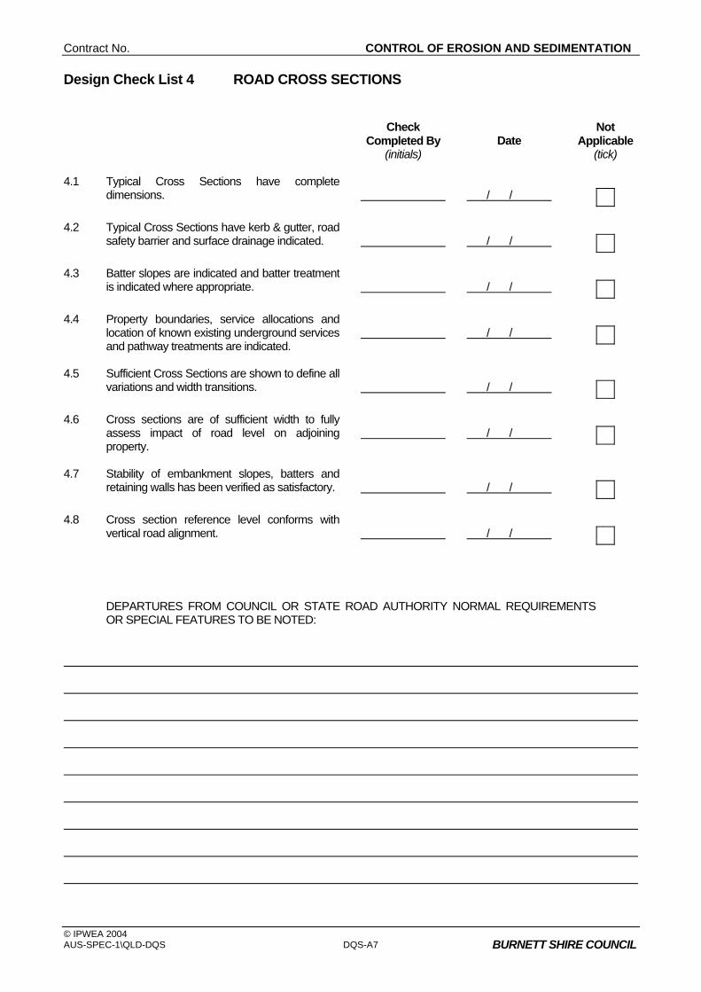
Design Check List 4 ROAD CROSS SECTIONS Check
Completed By (initials)
Date Not
Applicable (tick)
4.1 Typical Cross Sections have complete
dimensions.
/ /
4.2 Typical Cross Sections have kerb & gutter, road
safety barrier and surface drainage indicated.
/ /
4.3 Batter slopes are indicated and batter treatment
is indicated where appropriate.
/ /
4.4 Property boundaries, service allocations and
location of known existing underground services and pathway treatments are indicated.
/ /
4.5 Sufficient Cross Sections are shown to define all
variations and width transitions.
/ /
4.6 Cross sections are of sufficient width to fully
assess impact of road level on adjoining property.
/ /
4.7 Stability of embankment slopes, batters and
retaining walls has been verified as satisfactory.
/ /
4.8 Cross section reference level conforms with
vertical road alignment.
/ /
DEPARTURES FROM COUNCIL OR STATE ROAD AUTHORITY NORMAL REQUIREMENTS
OR SPECIAL FEATURES TO BE NOTED:

QUALITY ASSURANCE FOR DESIGN
© IPWEA 2004 DQS-A8 AUS-SPEC-1\QLD-DQS BURNETT SHIRE COUNCIL
Design Check List 5 ROAD AND INTERALLOTMENT DRAINAGE Check
Completed By (initials)
Date Not
Applicable (tick)
5.1 Drawings indicate existing surface drainage.
/ /
5.2 Hydrological data is the most current available.
/ /
5.3 Hydrologic and Hydraulic design calculations
are complete and fully recorded and available for audit.
/ /
5.4 Underground drainage and structures do not
conflict with services.
/ /
5.5 The designed drainage lines are compatible
with existing incoming lines and outgoing lines.
/ /
5.6 The length of line, type of pipe, size, class and
bedding requirements are indicated for each drainage line as well on the schedule of drainage elements.
/ /
5.7 Height of fill over drainage lines is within
allowable limits.
/ /
5.8 Drainage is provided for local depressions
eg median areas or areas adjacent to fills.
/ /
5.9 The effect of headwater and back-up water on
private property has been assessed.
/ /
5.10 Subsurface drainage has been provided when
required and clearly located by line and level, with details provided.
/ /
5.11 The need for batter drains has been considered
for fills and cuttings.
/ /
5.12 The height and energy level of downstream
drainage has been considered.
/ /
5.13 Drainage structures and flowpaths are located
so as to ensure safe vehicular and pedestrian transit.
/ /
5.14 Drainage structure number, setout, type and
pipe details indicated on the drainage plans and schedule of drainage elements.
/ /
5.15 Emergency flowpaths are located so as to
minimise impact on private property.
/ /
Contract No. CONTROL OF EROSION AND SEDIMENTATION
© IPWEA 2004 AUS-SPEC-1\QLD-DQS DQS-A9 BURNETT SHIRE COUNCIL
Check Completed By
(initials) Date
Not Applicable
(tick) 5.16 Road drainage has been provided in
accordance with any Conditions of Development Consent.
/ /
5.17 Interallotment drains have been designed in
accordance with Council's Specification and/or Australian Rainfall and Runoff (Edition 1987) or The Queensland Urban Drainage Manual.
/ /
5.18 Appropriate land stabilisation and velocity
controls have been implemented to pipe systems, open channels and embankments.
/ /
5.19 For allotments affected by flood controls, the
floor height controls are to be compatible with road and drainage levels.
/ /
DEPARTURES FROM COUNCIL OR STATE ROAD AUTHORITY NORMAL REQUIREMENTS
OR SPECIAL FEATURES TO BE NOTED:
QUALITY ASSURANCE FOR DESIGN
© IPWEA 2004 DQS-A10 AUS-SPEC-1\QLD-DQS BURNETT SHIRE COUNCIL
Design Check List 6 SIGNS AND MARKINGS Check
Completed By (initials)
Date Not
Applicable (tick)
6.1 Sign types, sizes, locations and support
structure details are shown on the drawings in accordance with the QMUTCD.
/ /
6.2 Pavement linemarking and pavement marking
type and setout is indicated on the drawings to meet the requirements of the QMUTCD.
/ /
6.3 Signs and linemarking have been designed in
accordance with any Conditions of Development Consent.
/ /
DEPARTURES FROM COUNCIL OR STATE ROAD AUTHORITY NORMAL REQUIREMENTS
OR SPECIAL FEATURES TO BE NOTED:
Contract No. CONTROL OF EROSION AND SEDIMENTATION
© IPWEA 2004 AUS-SPEC-1\QLD-DQS DQS-A11 BURNETT SHIRE COUNCIL
Design Check List 7 PAVEMENT DESIGN Check
Completed By (initials)
Date Not
Applicable (tick)
7.1 The pavement design and surface treatment is
shown clearly on the drawings and any variations are indicated on appropriate cross sections.
/ /
7.2 The pavement design complies with Council's
Pavement Design Specification.
/ /
7.3 Pavement Design is in accordance with any
Conditions of Development Consent.
/ /
7.4 Geotechnical data is assessed as adequate and
is held on the design file.
/ /
DEPARTURES FROM COUNCIL OR STATE ROAD AUTHORITY NORMAL REQUIREMENTS
OR SPECIAL FEATURES TO BE NOTED:

QUALITY ASSURANCE FOR DESIGN
© IPWEA 2004 DQS-A12 AUS-SPEC-1\QLD-DQS BURNETT SHIRE COUNCIL
Design Check List 8 BRIDGE/MAJOR CULVERT DESIGN Check
Completed By (initials)
Date Not
Applicable (tick)
8.1 The design has been performed by an Engineer
deemed to be suitably experienced in the relevant field by Council and eligible for Chartered Professional Membership of the Institution of Engineers, Australia
/ /
8.2 Geotechnical Data is assessed as adequate
and is held on the design file.
/ /
8.3 The type and functional dimensions of the
bridges meet AUSTROADS Bridge Design Codes, AS 3600, AS 1684, AS 1170, AS 4100.
/ /
8.4 The type and class of all materials are indicated
on the drawings.
/ /
8.5 Records of all significant design calculations are
available for audit.
/ /
8.6 The design complies with any Conditions of
Development Consent.
/ /
DEPARTURES FROM COUNCIL OR STATE ROAD AUTHORITY NORMAL REQUIREMENTS
OR SPECIAL FEATURES TO BE NOTED:

Contract No. CONTROL OF EROSION AND SEDIMENTATION
© IPWEA 2004 AUS-SPEC-1\QLD-DQS DQS-A13 BURNETT SHIRE COUNCIL
Design Check List 9 EROSION AND SEDIMENTATION CONTROL PLANS Check
Completed By (initials)
Date Not
Applicable (tick)
9.1 Both short term and long term erosion control
plans have been prepared using the guidelines within Council's Design Specification D7 and Construction Specification C211.
/ /
9.2 Erosion and Sedimentation Control has been
designed in accordance with any Conditions of Development Consent.
/ /
DEPARTURES FROM COUNCIL OR STATE ROAD AUTHORITY NORMAL REQUIREMENTS
OR SPECIAL FEATURES TO BE NOTED:


QUALITY ASSURANCE FOR DESIGN
© IPWEA 2004 AUS-SPEC-1\QLD-DQS DQS-B1 BURNETT SHIRE COUNCIL
ANNEXURE DQS-B EXAMPLE COMPILATION OF DRAWINGS A. ROADWORKS PLANS An example of the sequence of drawing sheets acceptable to Council in the compilation of a full set of Roadworks Drawings is set out as follows. Sheet No TOPIC
1 Development Consent Number Locality Sketch and Index of Sheets. 2 General Subdivision Plan with contour details and a clear indication of the extent of
work. 3 Typical Road Cross Sections showing road widths, pavement (design) configuration,
batter slopes, kerb and gutter types. 4. Plan and Longitudinal Section of each road showing setout data and services. 5. Drainage Plan and Schedule of Drainage Elements (Pipe lines and structures). 6. Drainage Profiles. 7. Drainage Structure Details 8. Road Cross Sections. 9. Intersection Layout Details. 10. Pavement Marking and Signposting 11. Erosion and Sedimentation Control Plans (short term and long term treatment). 12. Structure Details – Bridges, Retaining Walls, etc.
NOTES 1. Any one set of Roadworks Plans may require more than 1 sheet for each of the topics listed and may also require supplementary sheets for site specific details.
2. Scales are required to be nominated on all drawings and north points shown on all plan views.
.
Contract No. XYZ GEOMETRIC ROAD DESIGN
© IPWEA 2004 AUS-SPEC-1\QLD-D1 BURNETT SHIRE COUNCIL
QUEENSLAND
DEVELOPMENT DESIGN SPECIFICATION
D1
GEOMETRIC ROAD DESIGN
(Urban and Rural)

Contract No. XYZ GEOMETRIC ROAD DESIGN
© IPWEA 2004 AUS-SPEC-1\QLD-D1 BURNETT SHIRE COUNCIL
Amendment Record for this Specification Part
This Specification is Council’s edition of the AUS-SPEC generic specification part and includes Council’s primary amendments.
Details are provided below outlining the clauses amended from the Council edition of this AUS-SPEC Specification Part. The clause numbering and context of each clause are preserved. New clauses are added towards the rear of the specification part as special requirements clauses. Project specific additional script is shown in the specification as italic font.
The amendment code indicated below is ‘A’ for additional script ‘M’ for modification to script and ‘O’ for omission of script. An additional code ‘P’ is included when the amendment is project specific.
Amendment Sequence No.
Key Topic addressed in amendment
Clause No.
Amendment Code
Author Initials
Amendment Date
EXAMPLE 1
Provision for acceptance of nonconformance with deduction in Payment
XYZ.00 AP KP 2/6/97
1 D1.10 changed to 0.25%
2 Adopted by Burnett Shire Council
M RT 10/05/2006


Contract No. GEOMETRIC ROAD DESIGN
© IPWEA 2004 AUS-SPEC-1\QLD-D1
BURNETT SHIRE COUNCIL
CONTENTS CLAUSE PAGE
GENERAL .............................................................................................................................1
D1.01 SCOPE ....................................................................................................................................................1
D1.02 AIMS........................................................................................................................................................2
D1.03 REFERENCE AND SOURCE DOCUMENTS.........................................................................................2
D1.04 CONSULTATION ....................................................................................................................................3
D1.05 PLANNING CONCEPTS .........................................................................................................................3
D1.06 DRAWING REQUIREMENTS .................................................................................................................4
URBAN DESIGN CRITERIA .................................................................................................5
D1.07 ROAD HIERARCHY................................................................................................................................5
D1.08 ROAD NETWORK...................................................................................................................................8
D1.09 DESIGN SPEED......................................................................................................................................9
D1.10 LONGITUDINAL GRADIENT ..................................................................................................................9
D1.11 HORIZONTAL CURVES AND TANGENT LENGTHS ..........................................................................10
D1.12 VERTICAL CURVES.............................................................................................................................10
D1.13 SUPERELEVATION..............................................................................................................................11
D1.14 ROAD RESERVE CHARACTERISTICS...............................................................................................12
D1.15 CROSSFALL .........................................................................................................................................13
D1.16 VERGES AND PROPERTY ACCESS ..................................................................................................13
D1.17 INTERSECTIONS .................................................................................................................................13
D1.18 ROUNDABOUTS...................................................................................................................................15
D1.19 TRAFFIC CALMING..............................................................................................................................15
D1.20 PARKING...............................................................................................................................................17
D1.21 BUS ROUTES .......................................................................................................................................18
RURAL DESIGN CRITERIA ...............................................................................................19
D1.22 GENERAL .............................................................................................................................................19
D1.23 SIGHT DISTANCES..............................................................................................................................19
GEOMETRIC ROAD DESIGN Contract No. XYZ
© IPWEA 2004 AUS-SPEC-1\QLD-D1
BURNETT SHIRE COUNCIL
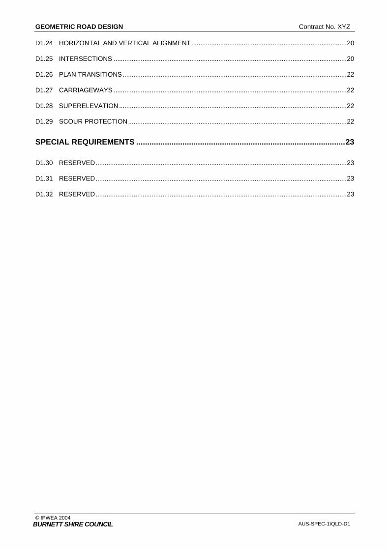
D1.24 HORIZONTAL AND VERTICAL ALIGNMENT......................................................................................20
D1.25 INTERSECTIONS .................................................................................................................................20
D1.26 PLAN TRANSITIONS............................................................................................................................22
D1.27 CARRIAGEWAYS .................................................................................................................................22
D1.28 SUPERELEVATION..............................................................................................................................22
D1.29 SCOUR PROTECTION.........................................................................................................................22
SPECIAL REQUIREMENTS ...............................................................................................23
D1.30 RESERVED...........................................................................................................................................23
D1.31 RESERVED...........................................................................................................................................23
D1.32 RESERVED...........................................................................................................................................23
Contract No. GEOMETRIC ROAD DESIGN
© IPWEA 2004 AUS-SPEC-1\QLD-D1 D1-1
BURNETT SHIRE COUNCIL
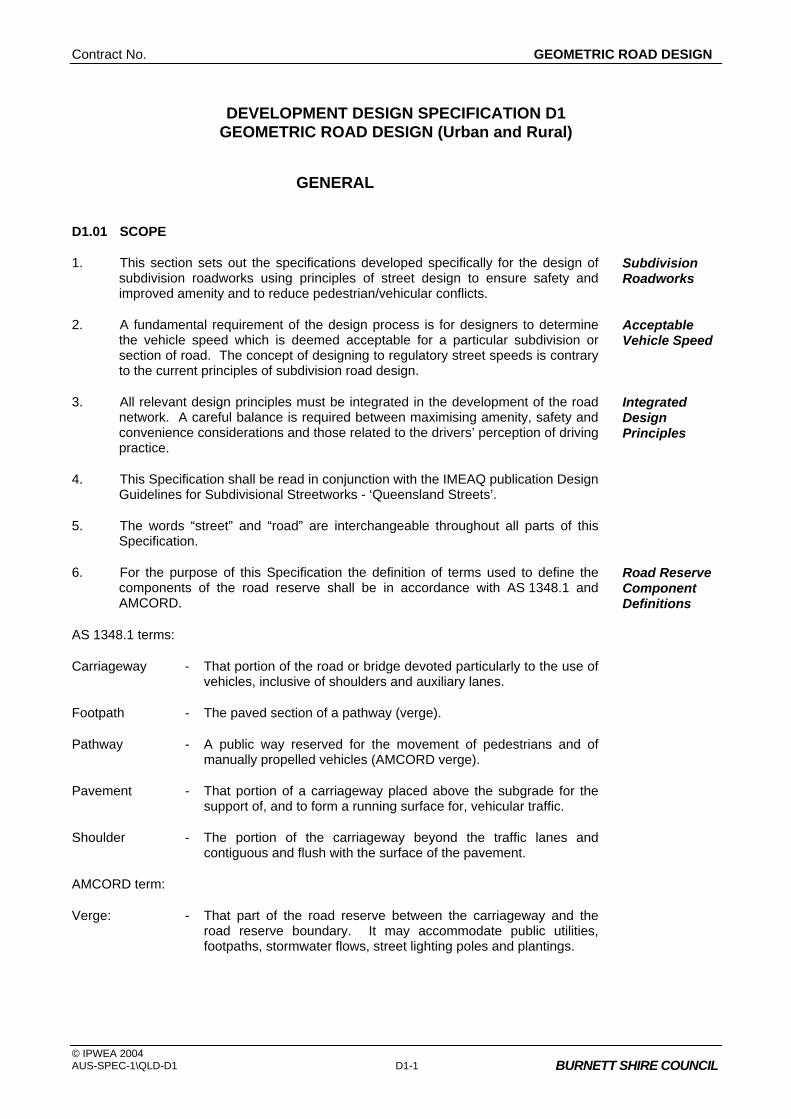
DEVELOPMENT DESIGN SPECIFICATION D1 GEOMETRIC ROAD DESIGN (Urban and Rural)
GENERAL
D1.01 SCOPE
1. This section sets out the specifications developed specifically for the design of subdivision roadworks using principles of street design to ensure safety and improved amenity and to reduce pedestrian/vehicular conflicts.
Subdivision Roadworks
2. A fundamental requirement of the design process is for designers to determine the vehicle speed which is deemed acceptable for a particular subdivision or section of road. The concept of designing to regulatory street speeds is contrary to the current principles of subdivision road design.
Acceptable Vehicle Speed
3. All relevant design principles must be integrated in the development of the road network. A careful balance is required between maximising amenity, safety and convenience considerations and those related to the drivers’ perception of driving practice.
Integrated Design Principles
4. This Specification shall be read in conjunction with the IMEAQ publication Design Guidelines for Subdivisional Streetworks - ‘Queensland Streets’.
5. The words “street” and “road” are interchangeable throughout all parts of this Specification.
6. For the purpose of this Specification the definition of terms used to define the components of the road reserve shall be in accordance with AS 1348.1 and AMCORD.
Road Reserve Component Definitions
AS 1348.1 terms:
Carriageway - That portion of the road or bridge devoted particularly to the use of vehicles, inclusive of shoulders and auxiliary lanes.
Footpath - The paved section of a pathway (verge).
Pathway - A public way reserved for the movement of pedestrians and of manually propelled vehicles (AMCORD verge).
Pavement - That portion of a carriageway placed above the subgrade for the support of, and to form a running surface for, vehicular traffic.
Shoulder - The portion of the carriageway beyond the traffic lanes and contiguous and flush with the surface of the pavement.
AMCORD term:
Verge: - That part of the road reserve between the carriageway and the road reserve boundary. It may accommodate public utilities, footpaths, stormwater flows, street lighting poles and plantings.

GEOMETRIC ROAD DESIGN Contract No. XYZ
© IPWEA 2004 AUS-SPEC-1\QLD-D1 D1-2
BURNETT SHIRE COUNCIL
D1.02 AIMS
1. The provision of a road system within a subdivision is to be designed so as to achieve the following aims:
• Provide convenient and safe access to all allotments for pedestrians, vehicles and cyclists.
• Provide safe, logical and hierarchical transport linkages with existing street system.
• Provide appropriate access for buses, emergency and service vehicles.
• Provide for a quality product that minimises maintenance costs.
• Provide a convenient way for public utilities.
• Provide an opportunity for street landscaping.
• Provide convenient parking for visitors.
• Have appropriate regard for the climate, geology and topography of the area.
D1.03 REFERENCE AND SOURCE DOCUMENTS
(a) Council Specifications
All Specifications for Design and Construction.
(b) Australian Standards AS 1348.1 - Road and traffic engineering – Glossary of terms, Road
design and construction. AS 2890.1 - Parking facilities: Off-street car parking. AS/NZS 3845 - Road safety barrier systems.
(c) QLD State Authorities Department of Local Government and Planning - Queensland Residential Design Guidelines, 1998
(d) Other AUSTROADS RURAL ROAD DESIGN, Guide to the Geometric Design of Rural
Roads. Guide Policy for the Geometric Design of Major Urban Roads. Guide to Traffic Engineering Practice: PART 5, Intersections at Grade PART 6, Roundabouts PART 10, Local Area Traffic Management PART 13, Pedestrians PART 14, Bicycles
The Institute of Municipal Engineering Australia, QLD Division. - Design Guidelines for Subdivisional Streetworks, 1995 -
‘Queensland Streets’. - Standard Drawings, 1997.

Contract No. XYZ GEOMETRIC ROAD DESIGN
© IPWEA 2004 AUS-SPEC-1\QLD-D1 D1-3
BURNETT SHIRE COUNCIL
ARRB Special Report No. 33, L E Comerford: A Review of Subdivision Road Design Criteria.
Commonwealth Department of Housing and Regional Development – 1995. Australian Model Code for Residential Development. (AMCORD). A National Resource Document for Residential Development.
Stapleton, C 1984: Streets Where We Live - A Manual for the Design of Safer Residential Estates.
Stapleton, C 1988, Dept of Transport South Australia: Planning & Road Design for New Residential Subdivisions.
Brindle, R 1988, ARRB: Planning & Design of the Local Distributor.
Colman, J 1978, ARRB: Streets for Living.
Pak-Poy Kneebone - 1989: Research Study into Road Characteristics for Residential Development.
D1.04 CONSULTATION
1. Designers are encouraged to consult with the Council and other relevant authorities prior to or during the preparation of design. Designers should in addition to requirements of this Specification ascertain specific requirements of these authorities as they relate to the designs in hand.
Council, Other Authorities
2. Public consultation on designs shall be provided where such action is required by Council’s current policy.
Public Consultation
3. The Designer shall obtain service plans from all relevant public utility authorities and organisations whose services may exist within the area of the proposed development. These services are to be plotted on the relevant drawings including the plan and cross-sectional views.
Public Utilities
D1.05 PLANNING CONCEPTS
1. In new areas (as distinct from established areas with a pre-existing road pattern) each class of route should reflect its role in the road hierarchy by its visual appearance and related physical design standards. Routes should differ in alignment and design standard according to the volume of traffic they are intended to carry, the desirable traffic speed, and other factors.
Road Hierarchy
2. The road pattern and width must be in conformity with that shown on any relevant Development Control Plan. In areas not covered by these plans, the pattern and width(s) will be determined by Council on their merits.
Conformance with DCP
3. The road network for residential developments should have clear legibility. Legibility
4. The road network should reinforce legibility by providing sufficient differentiation between the road functions.
Differentiation
5. Distinct landmark features such as watercourses, mature vegetation or ridge lines should be emphasised within the structural layout so as to enhance the legibility.
Landmark Features
6. Whilst legibility can be enhanced by introduced physical features such as pavement and lighting details, the road network should by its inherent design and functional distinction provide the necessary legibility.
Introduced Features
GEOMETRIC ROAD DESIGN Contract No. XYZ
© IPWEA 2004 AUS-SPEC-1\QLD-D1 D1-4
BURNETT SHIRE COUNCIL
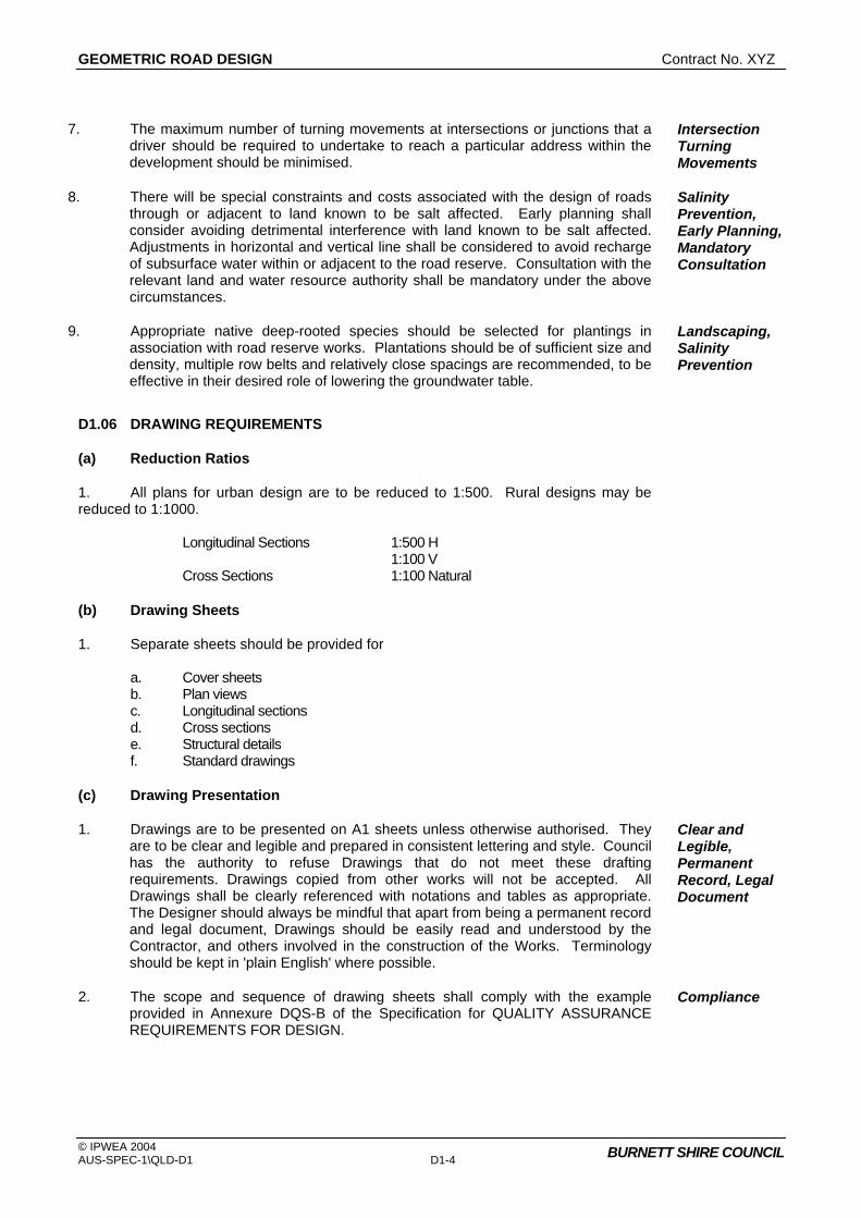
7. The maximum number of turning movements at intersections or junctions that a driver should be required to undertake to reach a particular address within the development should be minimised.
Intersection Turning Movements
8. There will be special constraints and costs associated with the design of roads through or adjacent to land known to be salt affected. Early planning shall consider avoiding detrimental interference with land known to be salt affected. Adjustments in horizontal and vertical line shall be considered to avoid recharge of subsurface water within or adjacent to the road reserve. Consultation with the relevant land and water resource authority shall be mandatory under the above circumstances.
Salinity Prevention, Early Planning, Mandatory Consultation
9. Appropriate native deep-rooted species should be selected for plantings in association with road reserve works. Plantations should be of sufficient size and density, multiple row belts and relatively close spacings are recommended, to be effective in their desired role of lowering the groundwater table.
Landscaping, Salinity Prevention
D1.06 DRAWING REQUIREMENTS
(a) Reduction Ratios
1. All plans for urban design are to be reduced to 1:500. Rural designs may be reduced to 1:1000. Longitudinal Sections 1:500 H 1:100 V Cross Sections 1:100 Natural
(b) Drawing Sheets
1. Separate sheets should be provided for a. Cover sheets b. Plan views c. Longitudinal sections d. Cross sections e. Structural details f. Standard drawings
(c) Drawing Presentation
1. Drawings are to be presented on A1 sheets unless otherwise authorised. They are to be clear and legible and prepared in consistent lettering and style. Council has the authority to refuse Drawings that do not meet these drafting requirements. Drawings copied from other works will not be accepted. All Drawings shall be clearly referenced with notations and tables as appropriate. The Designer should always be mindful that apart from being a permanent record and legal document, Drawings should be easily read and understood by the Contractor, and others involved in the construction of the Works. Terminology should be kept in 'plain English' where possible.
Clear and Legible, Permanent Record, Legal Document
2. The scope and sequence of drawing sheets shall comply with the example provided in Annexure DQS-B of the Specification for QUALITY ASSURANCE REQUIREMENTS FOR DESIGN.
Compliance

Contract No. XYZ GEOMETRIC ROAD DESIGN
© IPWEA 2004 AUS-SPEC-1\QLD-D1 D1-5
BURNETT SHIRE COUNCIL
(d) Certification
1. Drawings shall bear the signature of the design consultant and shall where required by the Council be certified as complying with the appropriate design specifications (D1 to D12). The certificate shall be in the format detailed in Annexure DQS-A of the Specification for QUALITY ASSURANCE REQUIREMENTS FOR DESIGN.
Design Consultant
URBAN DESIGN CRITERIA
D1.07 ROAD HIERARCHY
1. A hierarchical road network is essential to maximise road safety, residential amenity and legibility. Each class of road in the network serves a distinct set of functions and is designed accordingly. The design should convey to motorists the predominant function of the road. A typical hierarchy is shown on Figure D1.1.
Functionality
Figure D1.1 Typical Road Hierarchy
2. Four distinct levels of roads are: Access Place Access Street Collector Street Trunk Collector Street.
GEOMETRIC ROAD DESIGN Contract No. XYZ
© IPWEA 2004 AUS-SPEC-1\QLD-D1 D1-6
BURNETT SHIRE COUNCIL
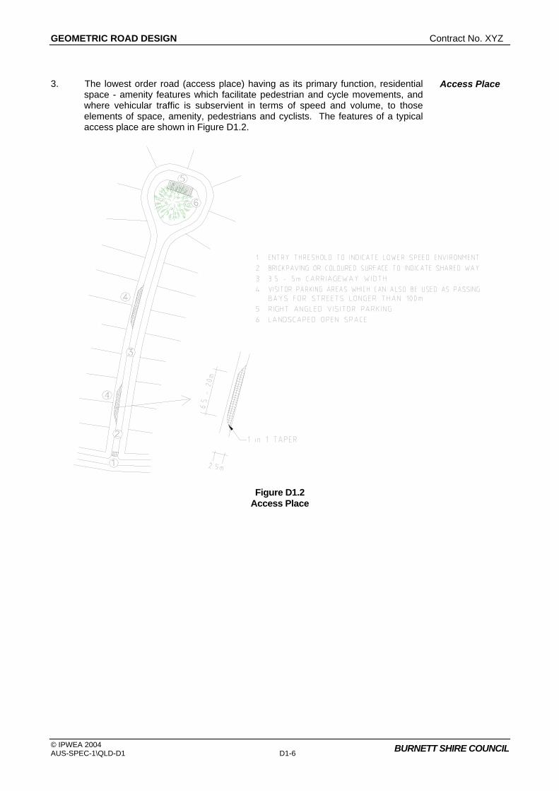
3. The lowest order road (access place) having as its primary function, residential space - amenity features which facilitate pedestrian and cycle movements, and where vehicular traffic is subservient in terms of speed and volume, to those elements of space, amenity, pedestrians and cyclists. The features of a typical access place are shown in Figure D1.2.
Access Place
Figure D1.2
Access Place

Contract No. XYZ GEOMETRIC ROAD DESIGN
© IPWEA 2004 AUS-SPEC-1\QLD-D1 D1-7
BURNETT SHIRE COUNCIL
4. The next level road (access street) as a local residential street should provide a balance between the status of that street in terms of its access and residential amenity functions. Resident safety and amenity are dominant but to a lesser degree than an access place. A typical access street is illustrated in Figure D1.3.
Access Street
Figure D1.3 Access Street
5. The second highest order road (collector street) has a residential function but also carries higher volumes of traffic collected from lower order streets. A reasonable level of residential amenity and safety is maintained by restricting traffic volumes and speeds, however, amenity and resident safety do not have the same priority as access or local streets. A typical collector street is shown in Figure D1.4.
Collector Street
Figure D1.4
GEOMETRIC ROAD DESIGN Contract No. XYZ
© IPWEA 2004 AUS-SPEC-1\QLD-D1 D1-8
BURNETT SHIRE COUNCIL
Collector Street
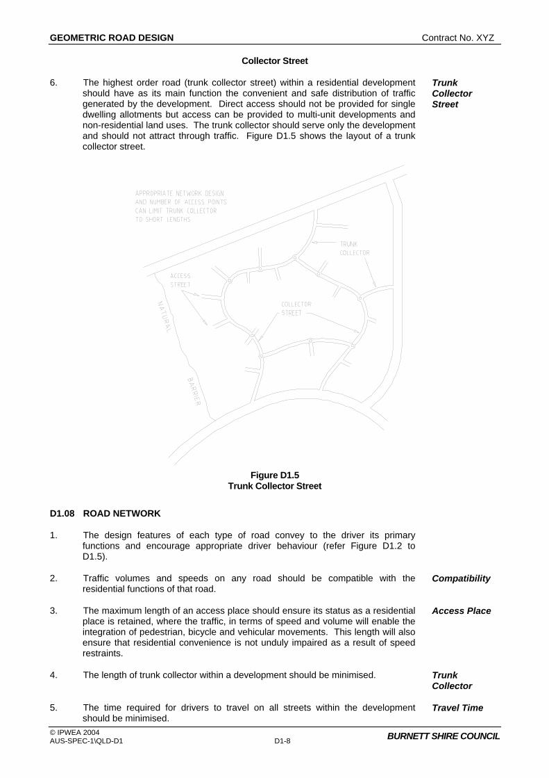
6. The highest order road (trunk collector street) within a residential development should have as its main function the convenient and safe distribution of traffic generated by the development. Direct access should not be provided for single dwelling allotments but access can be provided to multi-unit developments and non-residential land uses. The trunk collector should serve only the development and should not attract through traffic. Figure D1.5 shows the layout of a trunk collector street.
Trunk Collector Street
Figure D1.5
Trunk Collector Street
D1.08 ROAD NETWORK
1. The design features of each type of road convey to the driver its primary functions and encourage appropriate driver behaviour (refer Figure D1.2 to D1.5).
2. Traffic volumes and speeds on any road should be compatible with the residential functions of that road.
Compatibility
3. The maximum length of an access place should ensure its status as a residential place is retained, where the traffic, in terms of speed and volume will enable the integration of pedestrian, bicycle and vehicular movements. This length will also ensure that residential convenience is not unduly impaired as a result of speed restraints.
Access Place
4. The length of trunk collector within a development should be minimised. Trunk Collector
5. The time required for drivers to travel on all streets within the development should be minimised.
Travel Time

Contract No. XYZ GEOMETRIC ROAD DESIGN
© IPWEA 2004 AUS-SPEC-1\QLD-D1 D1-9
BURNETT SHIRE COUNCIL
6. Where access places form part of a pedestrian or bicycle network, access links should provide suitable connectivity with adjoining access places or open space systems so as to ensure such pedestrian and bicycle network are functionally efficient.
Pedestrian or Bicycle Network
7. The road network should ensure that no road links with another road which is more than two levels higher or lower in the hierarchy. In exceptional circumstances roads may link with others that are more than two levels apart, however, no access place or access street should have access to an access-controlled arterial road.
Road Links
8. Connections between internal roads should be T-junctions or controlled by roundabouts.
Internal Road Connections
9. The road layout should conform to the requirements of the external road network and satisfy the transport provisions of an outline development plan.
Transport Provisions
10. The external road network should be designed and located to provide routes which are more convenient for potential through traffic within the network. Major roads should be provided at intervals of no more than 1.5 km and should be complete and of adequate capacity to accommodate through network movements. The internal road system should not provide through routes that are more convenient than the external road network.
External Road Network
D1.09 DESIGN SPEED
1. Design speed is generally used as the basic parameter in the specification of design standards, determining the minimum design value for other elements. ‘Queensland Streets’ use the 85 percentile maximum speed of traffic within the street. This is similar to the ‘Speed Environment’ used in AUSTROADS Guide to the Geometric Design of Rural Roads. Vehicular speeds are also limited by road intersections as well as changes in horizontal and vertical alignment.
Guidelines
2. Adoption of a low design speed discourages speeding, however, where vertical or horizontal curves of low design speed are located in otherwise high speed sections (tangents) the result is a potentially dangerous section of road. It should be recognised that in low standard roads, operating speeds will tend to be in excess of arbitrary speed standards. Attention should be given to ensuring that potentially hazardous features are visible to the driver and adopting traffic engineering measures which will help a driver avoid errors of judgement.
Low Speeds
Hazardous Features
3. Generally the following design speeds should be adopted: Access Place 25 km/h Access Street 40 km/h Collector Street 60 km/h Trunk Collector Street 60/80 km/h
4. The need for road safety barriers shall be assessed and designed in accordance with AS/NZS 3845.
Road Safety Barriers
D1.10 LONGITUDINAL GRADIENT
1. A general minimum gradient of 0.3 per cent should be adopted. In very flat conditions it may be reduced to 0.25 per cent. Where underground drainage with gully pits or other special works are used it is preferable to allow near level grades rather than reverting to the unsatisfactory device of introducing artificial undulations. Variable crossfall may be necessary to produce the required grade in the gutter. Maximum recommended grades for all street types are as shown in ‘Queensland Streets’.
Flat Terrain
GEOMETRIC ROAD DESIGN Contract No. XYZ
© IPWEA 2004 AUS-SPEC-1\QLD-D1 D1-10
BURNETT SHIRE COUNCIL
2. Longitudinal grade of the minor street on the approach to an intersection should not exceed 4 per cent, the actual gradient being dependent on the type of terrain. Design of the road alignment and the grades used are interrelated. A steep grade on a minor side street is undesirable if vehicles have to stand waiting for traffic in the major road.
Intersections
3. Turning circles in cul-de-sacs on steep grades should have grades less than 5 per cent.
Cul-de-Sacs
D1.11 HORIZONTAL CURVES AND TANGENT LENGTHS
1. The horizontal alignment of a road is normally in a series of tangents (straights) and curves which may be connected by transition curves. The choice of the horizontal alignment is normally determined from the design speeds for a particular street within the road hierarchy as described in Clause D1.09. Designers should ensure that, for a given design speed, the minimum radius of curvature utilised is such that drivers can safely negotiate the curve. Curves which progressively tighten produce an uncomfortable sense of disorientation and alarm. Sudden reverse curves which drivers cannot anticipate also have a potential to cause similar conditions.
Speed/Radius Relation
2. Where speed restriction is provided by curves in the street alignment the relationship between the radius of the curve and the desired vehicle speed is given in ‘Queensland Streets’.
Speed Restriction
3. To determine appropriate lengths for tangents between speed restrictions, which may be curves, narrow sections or other obstructions, refer to ‘Queensland Streets’.
Tangent Length
4. Sight distance on curves is determined by formula, values of which are tabulated in ‘Queensland Streets’.
D1.12 VERTICAL CURVES
1. Vertical curves will be simple parabolas and should be used on all changes of grade exceeding 1 per cent. The length of the crest vertical curve for stopping sight distance should conform with ‘Queensland Streets’.
Criteria
2. For adequate riding comfort, lengths of sag vertical curves should conform with ‘Queensland Streets’.
Riding Comfort
3. Junctions of roads should be located at a safe distance from a crest, determined by visibility from the side road. Location of a side road at a crest should only occur if there is no suitable alternative.
Side Road Junctions
4. Drainage poses a practical limit to the length of sag curves and a maximum length (in metres) of 15 times the algebraic sum of the intersecting vertical grades (expressed as a percentage) has been suggested. This is to avoid water ponding in excessively flat sections of kerb and gutter. A minimum grade of 0.25 per cent should be maintained in the kerb and gutter. This may require some warping of road cross sections at sag points.
Sag Curves
5. The three dimensional coordination of the horizontal and vertical alignment of a road should be aimed at improved traffic safety and aesthetics. Economic considerations often require a compromise with aesthetic considerations. The following principles should be applied:
Horizontal and Vertical Alignment Coordination
• The design speed of the road in both horizontal and vertical planes should be of the same order.

Contract No. XYZ GEOMETRIC ROAD DESIGN
© IPWEA 2004 AUS-SPEC-1\QLD-D1 D1-11
BURNETT SHIRE COUNCIL
• Combined horizontal and vertical stopping sight distance and minimum sight distance should be considered three dimensionally.
• Sharp horizontal curves should not be introduced at or near the crest of a vertical curve. A horizontal curve should leave the vertical curve and be longer than the vertical curve.
• A short vertical curve on a long horizontal curve or a short tangent in the gradeline between sag curves may adversely affect the road's symmetry and appearance.
D1.13 SUPERELEVATION
1. The use of superelevation in association with horizontal curves is an essential aspect of geometric design of roads with design speeds in excess of 60 km/h. Local access roads which are designed for speeds of 40 km/h or less and with curves of 60m radius or less generally have the pavement crowned on a curve instead of superelevation. Design standards for such curves have little meaning as drivers usually cut the corners and rely on friction to hold them on a curved path. As the radius of the curve falls, friction becomes more important than superelevation.
Low Design Speed, Crowned Pavement
2. The maximum superelevation for urban roads of higher design speeds should be 6 per cent. Any increase in the longitudinal grade leading to excessive crossfall at intersections should be considered with caution. While it is desirable to superelevate all curves, negative crossfall should be limited to 3 per cent.
High Design Speed
3. In general, curve radii larger than the minimum and superelevation rates less than the maximum should be used where possible. The minimum radius of curves is determined by the design speed, the minimum superelevation (or maximum adverse crossfall) at any point on the circular portion of the curve, and the maximum coefficient of side friction which allows safe lane changing. This is 0.15 where there is positive superelevation and 0.12 where there is adverse crossfall. The coefficient of side friction depends upon the type and condition of tyres, the pavement, and on speed.
Criteria
4. Recommendations for minimum curve radii (in metres) on major urban roads under varying superelevation/crossfall are shown in Table D1.1.
Table D1.1 Minimum Radius of Curvature
Design Speed km/h
60 70 80
Minimum Superelevation (%)
5 4 3 2 1
145 150 160 170 180
195 205 215 230 245
255 265 280 300 315
Maximum Crossfall (%)
0 1 2 3
190 260 285 315
260 355 390 430
340 460 505 560
(Source: NAASRA (Now AUSTROADS), Guide policy for the geometric design of major urban roads.)

GEOMETRIC ROAD DESIGN Contract No. XYZ
© IPWEA 2004 AUS-SPEC-1\QLD-D1 D1-12
BURNETT SHIRE COUNCIL
5. Plan transitions are desirable on superelevated curves for appearance and to provide a convenient length in which to apply the superelevation. On urban roads, superelevation may be conveniently applied to the road cross section by shifting the crown to 2m from the outer kerb. The axis of rotation of the cross section for urban roads will normally be the kerb grading on either side which best enables access to adjacent properties and intersections. On the outside of superelevation, or where the longitudinal grade of the gutter is less than 0.5 per cent, a crossfall of 63mm in a 450mm wide gutter may be adopted.
Transitions, Offset Crowns
D1.14 ROAD RESERVE CHARACTERISTICS
1. The cross section of the road reserve must provide for all functions that the road is expected to fulfil, including the safe and efficient movement of all users, provision for parked vehicles, acting as a buffer from traffic nuisance for residents, the provision of public utilities and streetscaping. ‘Queensland Streets’ details characteristics of the road reserve.
Cross Section Provisions
2. The carriageway width must allow vehicles to proceed safely at the operating speed intended for that level of road in the network and with only minor delays in the peak period. This must take into consideration the restrictions caused by parked vehicles where it is intended or likely that this will occur on the carriageway. Vehicles include trucks, emergency vehicles and, on some roads, buses. (Refer to Clause D1.21 for bus routes.)
Operational Aspects
3. The safety of pedestrians and cyclists where it is intended they use the carriageway must also be assured by providing sufficient width.
Pedestrians, Cyclists
4. The carriageway width should also provide for unobstructed access to individual allotments. Drivers should be able to comfortably enter or reverse from an allotment in a single movement, taking into consideration the possibility of a vehicle being parked on the carriageway opposite the driveway.
Access to Allotments
5. The design of the carriageway should discourage drivers from travelling above the intended speed by reflecting the functions of the road in the network. In particular the width and horizontal and vertical alignment should not be conducive to excessive speeds.
Discourage Speeding
6. Appropriate verge width should be provided to enable the safe location, construction and maintenance of required for paths and public utility services (above or below ground) and to accommodate the desired level of streetscaping. Wherever possible services should be located in common trenches.
Verge Width
7. The verge when considered in conjunction with the horizontal alignment and permitted fence and property frontage treatments should provide appropriate sight distances, taking into account expected speeds and pedestrian and cyclist movements.
Sight Distance Across Verge
8. Stopping sight distances and junction or intersection sight distances, provided by the verge, should be based on the intended speeds for each road type.

Contract No. XYZ GEOMETRIC ROAD DESIGN
© IPWEA 2004 AUS-SPEC-1\QLD-D1 D1-13
BURNETT SHIRE COUNCIL
D1.15 CROSSFALL
1. Desirably, roads should be crowned in the centre. Typical pavement crossfalls on straight roads are: Pavement Type Crossfall
Bituminous seal coat 3 per cent Bituminous concrete pavement 2.5 per cent Cement concrete pavement 2 per cent (Source: NAASRA (Now AUSTROADS), Guide policy for geometric design of major
urban roads.)
2. There are many factors affecting levels in urban areas which force departures from these crossfalls. Refer to Austroad – rate of rotation
Offset Crown Lines
Rate of Change
3. The crossfall on a collector or trunk collector street should take precedence over the grade in minor side streets. Standard practice is to maintain the crossfall on the major road and adjust the minor side street levels to suit. The crossfall in side streets should be warped quickly either to a crown or a uniform crossfall depending on the configuration of the side street. A rate of change of grade of two per cent in the kerb line of the side street relative to the centre line grading is a reasonable level.
Precedence
D1.16 VERGES AND PROPERTY ACCESS
1. A suitable design for the verge will depend on utility services, the width of footpath, access to adjoining properties, likely pedestrian usage and preservation of trees. Low level footpaths are undesirable but may be used if normal crossfalls are impracticable. Crossfalls in footpath paving should not exceed 2.5 per cent, in accordance with AUSTROADS Guide to Traffic Engineering Practice, PART 13, Pedestrians. Longitudinal grade usually parallels that of the road and this may be steeper than 5 per cent.
Criteria
2. Differences in level across the road between road reserve boundaries may be accommodated by:
Options
• Cutting at the boundary on the high side and providing the verge at normal level and crossfall.
• Battering at the boundary over half the verge width with the half against the kerb constructed at standard crossfall.
• A uniform crossfall across the carriageway.
• The lower verge being depressed below the gutter level.
3. The above measures can be used singularly or combined. The verge formation should extend with a 0.5m berm beyond the road reserve boundary.
4. The Designer shall design a vehicular driveway centreline profile for the property access and check this design using critical car templates, available from Council, to ensure that vehicles can use the driveway satisfactorily.
Driveway Profile
D1.17 INTERSECTIONS
1. The design of intersections or junctions should allow all movements to occur Traffic Volumes

GEOMETRIC ROAD DESIGN Contract No. XYZ
© IPWEA 2004 AUS-SPEC-1\QLD-D1 D1-14
BURNETT SHIRE COUNCIL
safely without undue delay. Projected traffic volumes should be used in designing all intersections or junctions on trunk collector streets.
2. Intersection design for the junction of subdivision roads with existing state rural or urban roads and national highways should generally be in accordance with the publication AUSTROADS Guide to Traffic Engineering Practice, PART 5, Intersections at Grade.
State Roads, National Highways
3. Intersections with state roads or national highways are to be designed, approved and constructed in accordance with the requirements of the Queensland Department of Main Roads.
Approval of State Road Authority
4. Where major intersections are required to serve a development complete reconstruction of the existing road pavements will be necessary where the speed environment and irregularity of the existing road pavement may endanger the safety of traffic in the locality.
Existing Road Pavement
5. Intersections should be generally located in such a way that: Criteria
• The streets intersect preferably at right-angles and not less than 70°.
• The landform allows clear sight distance on each of the approach legs of the intersection.
• The minor street intersects the convex side of the major street.
• The vertical grade lines at the intersection do not impose undue driving difficulties.
• The vertical grade lines at the intersection will allow for any direct surface drainage.
• Two minor side streets intersecting a major street in a left-right staggered pattern should have a minimum centre-line spacing of 50m to provide for a possible right-turn auxiliary lane on the major street.
• A right-left manoeuvre between the staggered streets is preferable, avoiding the possibility of queuing in the major street.
6. Adequate stopping and sight distances are to be provided for horizontal and vertical curves at all intersections.
Sight Distance
7. Where required, appropriate provision should be made for vehicles to park safely.
Parking
8. The drainage function of the carriageway and/or road reserve must be satisfied by the road reserve cross-section profile.
Drainage
9. All vehicle turning movements are accommodated utilising AUSTROADS Design Vehicles and Turning Templates, as follows:
Turning Movements
• For intersection turning movements involving trunk collector streets, the "design semi-trailer" with turning path radius 15m.
• For intersection turning movements involving access streets or collector streets, but not trunk collector streets, the "design single unit" bus with turning path radius 13m.
• For intersection turning movements on access places but not involving trunk collector streets, collector streets or access streets, the garbage collection vehicle used by the local authority as discussed in ‘Queensland Streets’.
Contract No. XYZ GEOMETRIC ROAD DESIGN
© IPWEA 2004 AUS-SPEC-1\QLD-D1 D1-15
BURNETT SHIRE COUNCIL
• For turning movements at the head of cul-de-sac access places sufficient area is provided for the "design single unit" truck to make a three-point turn or where the length of the cul-de-sac is less than 60m for the "design car" to make a three-point turn. Where driveway entrances are to be used for turning movements, the required area is to be designed and constructed to withstand the relevant loads. Refer to ‘Queensland Streets’ for additional discussion on turning areas.
10. Turning radii at intersections or driveways on trunk collector streets accommodate the intended movements without allowing desired speeds to be exceeded.
Turning Radii
11. On bus routes 3-centred curves with radii 7m, 10m, 7m are used at junctions and intersections.
Bus Routes
D1.18 ROUNDABOUTS
1. Roundabouts are to be approved by the Council. Approval
2. Roundabouts should generally be designed in accordance with the requirements of the publication AUSTROADS Guide to Traffic Engineering Practice - PART 6 Roundabouts. Designs adopting alternative criteria will be considered on their merits. Roundabout design should generally comply with the following:
Criteria
• entry width to provide adequate capacity
• adequate circulation width, compatible with the entry widths and design vehicles eg. buses, trucks, cars.
• central islands of diameter sufficient only to give drivers guidance on the manoeuvres expected
• deflection of the traffic to the left on entry to promote gyratory movement
• adequate deflection of crossing movements to ensure low traffic speeds
• a simple, clear and conspicuous layout
• design to ensure that the speed of all vehicles approaching the intersection will be less than 50 km/h.
D1.19 TRAFFIC CALMING
1. Traffic calming devices are to be approved by the Council. Approval
2. Calming devices such as thresholds, slowpoints, speed humps, chicanes and splitter islands should be designed in accordance with the requirements of the publication AUSTROADS Guide to Traffic Engineering Practice - PART 10, Local Area Traffic Management (LATM). Devices designs should generally comply with the following:
Criteria

GEOMETRIC ROAD DESIGN Contract No. XYZ
© IPWEA 2004 AUS-SPEC-1\QLD-D1 D1-16
BURNETT SHIRE COUNCIL
(a) Streetscape
• reduce the linearity of the street by segmentation
• avoid continuous long straight lines (eg. kerb lines)
• enhance existing landscape character
• maximise continuity between existing and new landscape areas.
(b) Location of Devices/Changes
• devices other than at intersections should be located to be consistent with streetscape requirements
• existing street lighting, drainage pits, driveways, and services may decide the exact location of devices
• slowing devices are optimally located at spacings of 100-150m.
(c) Design Vehicles
• emergency vehicles must be able to reach all residences and properties
• access streets with a 'feeding' function between arterial roads and minor access streets might be designed for a AUSTROADS Design Single Unit Truck/Bus
• where bus routes are involved, buses should be able to pass without mounting kerbs and with minimised discomfort to passengers.
• in newly developing areas where street systems are being developed in line with LATM principles, building construction traffic must be provided for.
(d) Control of Vehicle Speeds
• maximum vehicle speeds can only be reduced by deviation of the travelled path. Pavement narrowings have only minor effects on average speeds, and usually little or no effect on maximum speeds
• speed reduction can be achieved using devices which shift vehicle paths laterally (slow points, roundabouts, corners) or vertically (humps, platform intersections, platform pedestrian/school/bicycle crossings)
• speed reduction can be helped by creating a visual environment conducive to lower speeds. This can be achieved by 'segmenting' streets into relatively short lengths (less than 300m), using appropriate devices, streetscapes, or street alignment to create short sight lines

Contract No. XYZ GEOMETRIC ROAD DESIGN
© IPWEA 2004 AUS-SPEC-1\QLD-D1 D1-17
BURNETT SHIRE COUNCIL
(e) Visibility Requirements (sight distance)
• adequate critical sight distances should be provided such that evasive action may be taken by either party in a potential conflict situation. Sight distances should relate to likely operating speeds
• sight distance to be considered include those of and for pedestrians and cyclists, as well as for drivers
• night time visibility of street features must be adequate. Speed control devices particularly should be located near existing street lighting if practicable, and all street features/furniture should be delineated for night time operation. Additional street lighting shall be provided by the Developer at proposed new speed control devices located away from existing street lighting.
(f) Critical Dimensions
Many devices will be designed for their normal use by cars, but with provision (such as mountable kerbs) for larger vehicles. Some typical dimensions include:
• pavement narrowings
− single lane 3.50m between kerbs − 3.75m between obstructions − two lane 5.50m minimum between kerbs
• bicycle lanes (including adjacent to pavement narrowings) - 1.2m absolute minimum (1.0m in special circumstances in accordance with AUSTROADS Guide to Traffic Engineering Practice – PART 14, Bicycles.)
• plateau or platform areas
− 75mm to 150 mm height maximum, with 1 in 15 ramp slope
• width of clear sight path through slowing devices
− 1.0m maximum
(ie. the width of the portion of carriageway which does not have its line of sight through the device blocked by streetscape materials, usually vegetation)
• dimensions of mountable areas required for the passage of large vehicles to be determined by appropriate turning templates.
D1.20 PARKING
1. The parking requirements for normal levels of activity associated with any land use should be accommodated on-site.
On Site
2. All on-site parking should be located and of dimensions that allow convenient and safe access and usage.
3. Adequate parking should be provided within the road reserve for visitors, service vehicles and any excess resident parking since a particular dwelling may generate a high demand for parking. Such parking is to be convenient to dwellings.
Road Reserve Parking
4. The availability of parking should be adequate to minimise the possibility of driveway access being obstructed by cars parked on the opposite side of the
Obstruction

GEOMETRIC ROAD DESIGN Contract No. XYZ
© IPWEA 2004 AUS-SPEC-1\QLD-D1 D1-18
BURNETT SHIRE COUNCIL
street.
5. On single lane access streets parking spaces should be provided within the verge. Such parking should be well defined and an all-weather surface provided. Such parking shall not restrict the safe passage of vehicular and pedestrian traffic.
Verge Parking
6. Parking spaces provided on the verge or carriageway should be of adequate dimensions, convenient and safe to access.
7. For non-residential land uses the opportunity for joint use of parking should be maximised by being shared by a number of complementing uses.
Joint Use
8. Two car parking spaces (which may be in tandem) are provided on-site for each single dwelling allotment.
2 Spaces
9. Three spaces are provided on-site for each two dwelling units for multi-unit residential developments.
3 Spaces
10. Of the on-site parking one space for each residential unit is provided within the allowable building area and has a minimum dimension of 5m by 3m.
On-Site Space Dimension
11. On single lane carriageways one space for each two allotments is constructed on the verge within 25m of each allotment, with scope to provide one additional space for single dwelling allotments or for each two units in a multi-unit development if required at a future time.
Future Spaces
12. On single lane carriageways a number of verge spaces are combined to provide for short term truck parking within 40m of any allotment.
Short Term Truck Parking
13. A single (car) space is 6.5m by 2.5m and combined spaces are 13.0m by 2.5m (for two cars) and 20m by 2.5m (for truck parking) with adequate tapers at both ends to allow the necessary parking manoeuvres determined by using AUSTROADS Turning Templates.
Road Reserve Space Dimensions
14. All verge spaces and indented parking areas are constructed of concrete, interlocking pavers, lawn pavers, bitumen with crushed rock or other suitable base material and are designed to withstand the loads and manoeuvring stresses of vehicles expected to use those spaces.
Verge Spaces, Indented Parking
15. Right-angled parking is provided only on access places and access streets where speeds do not exceed 40 km/h.
Right-angled Parking
16. The number of on-site parking spaces for non-residential land uses conforms to parking standards as determined by the relevant authority.
17. The layout and access arrangements for parking areas for non-residential land uses should conform to Australian Standard 2890.1.
18. Refer to ‘Queensland Streets’ for additional discussion on parking.
D1.21 BUS ROUTES
1. Bus routes will normally be identified by Council. It is important that the road hierarchy adequately caters for buses. The main criteria in determining the location of bus routes is that no more than 5% of residents should have to walk in excess of 400 metres to catch a bus. Normally roads above the access street in the hierarchy are designed as bus routes. Table D1.2 details minimum criteria for bus route design.
Criteria

Contract No. XYZ GEOMETRIC ROAD DESIGN
© IPWEA 2004 AUS-SPEC-1\QLD-D1 D1-19
BURNETT SHIRE COUNCIL
Table D1.2 Bus Route Criteria
Road Carriageway Width (min)
Stops (Spacing) Bays
Collector* 9m 400 metre ** Single
Trunk collector 11m 400 metre Shelters***
Arterial 13m 400 metre Shelters and Bays
* Collector roads not identified as bus routes may have 7m
carriageways
** Loop roads with single entry/exit only require stops and bays on one side road.
*** Shelters are subject to Council's requirements.
RURAL DESIGN CRITERIA
D1.22 GENERAL
1. In addition to the foregoing sections this section specifically applies to all those sites identified as being suited to rural subdivisions inclusive of rural home sites and hobby farms types of developments.
2. Design speed is to be generally used as the basic parameter of design standards and the determination of the minimum design value for other elements in rural subdivisions is to be based on the concept of a "speed environment" as outlined in AUSTROADS Guide to the Geometric Design of Rural Roads and ‘Queensland Streets’.
Design Speed
3. Where appropriate superelevation, widening and centreline shift and their associated transitions are to comply with ‘Queensland Streets’ or AUSTROADS Guide.
4. Where the table drain is likely to scour, a stone pitched or suitably lined dish drain is to be constructed along the invert. Also for grades of less than 0.8%, the inverts of the drain are to be lined to prevent siltation.
Table Drain
5. All rural subdivisions should be designed to restrict access to major roads.
6. All rural residential subdivisions will be required to provide kerb and gutter, within the road reserve, on both sides of roads and piped drainage will generally be required.
Kerb and Gutter
7. Access should be limited to one point on to access, collector, trunk collector or arterial road networks.
Access
D1.23 SIGHT DISTANCES
1. Stopping and minimum sight distances. Stopping sight distance should be provided at all points on the road in accordance with ‘Queensland Streets’.
Stopping Distance
2. Stopping distance is the sum of the braking distance and the distance the vehicle travels during a reaction time of 1.5 seconds, and may be calculated using the
Braking Distance

GEOMETRIC ROAD DESIGN Contract No. XYZ
© IPWEA 2004 AUS-SPEC-1\QLD-D1 D1-20
BURNETT SHIRE COUNCIL
following formula:
d = 0 42254
2
. V Vf
+
Where d = stopping distance (m) V = speed of vehicle (km/h) f = coefficient of longitudinal deceleration (Source: AUSTROADS Guide to the Geometric Design of Rural Roads,)
3. Recommended sight distances are shown in ‘Queensland Streets’.
D1.24 HORIZONTAL AND VERTICAL ALIGNMENT
1. Horizontal and vertical curves are to be designed generally to the requirements of AUSTROADS - Guide to Geometric Design of Rural Roads. These requirements are essential to satisfy the safety and performance of proper road design. Roads having both horizontal and vertical curvature should be designed to conform with the terrain to achieve desirable aesthetic quality and being in harmony with the landform.
Criteria
D1.25 INTERSECTIONS
1. Intersections should generally be designed in accordance with the publication AUSTROADS Guide to Traffic Engineering Practice - Part 5, Intersections at Grade. Generally intersections with existing main and local roads will conform to the layouts shown in Figure D1.3 below. The type of intersection required will depend on existing and planned connecting roads.
Criteria
2. Adequate sight distance should be provided at intersections both horizontally and vertically. Each intersection location shall be examined for conformance with the criteria for Approach Sight Distance (ASD), Entering Sight Distance (ESD) and Safe Intersection Sight Distance (SISD).
ASD relates to the ability of drivers to observe the roadway layout at an anticipated approach speed.
ESD relates to the driver entering the intersection from a minor road and ability to observe the roadway layout and assess traffic gaps.
SISD relates to an overall check that vehicles utilising the intersection have sufficient visibility to allow reaction and deceleration so as to provide adequate stopping distance in potential collision situations.
Tabulated speed/sight distance requirements together with detailed explanations for each of the sight distance criteria are given in Part 5 of the AUSTROADS Guide, Intersections at Grade. Repositioning of an intersection may be required to obtain conformance with the sight distance criteria.
Sight Distance

Contract No. XYZ GEOMETRIC ROAD DESIGN
© IPWEA 2004 AUS-SPEC-1\QLD-D1 D1-21
BURNETT SHIRE COUNCIL
Figure D1.3 Typical Rural Intersection Treatments
Source: AUSTROADS Guide to Traffic Engineering Practice PART 5, Intersections at Grade.
3. Staggered-T arrangements proposed for rural cross-intersections should preferably be of the “right to left” type. This arrangement eliminates traffic queuing in the major road, the need for additional pavement for right turn lanes and greater stagger length associated with “left to right” T-intersections. Figures and discussion on staggered-T treatments are given in Part 5 of the AUSTROADS Guide, Intersections at Grade.
Staggered-T Intersections
GEOMETRIC ROAD DESIGN Contract No. XYZ
© IPWEA 2004 AUS-SPEC-1\QLD-D1 D1-22
BURNETT SHIRE COUNCIL
D1.26 PLAN TRANSITIONS
1. A plan transition is the length over which widening and shift is developed from the "tangent-spiral" point to the "spiral-curve" point; ie, the length between the tangent and the curve. In urban road design it is often impracticable to use plan transitions as kerb lines are fixed in plan and any shift requires carriageway widening. Widening on horizontal curves compensates for differential tracking of front and rear wheels of vehicles; overhang of vehicles; and transition paths. Where proposed roads are curved, the adequacy of carriageway width should be considered.
Widening and Shift on Curves
2. Abrupt changes in crossfall, can cause discomfort in travel and create a visible kink in the kerb line. Refer Austroad – Rate of Rotation
Crossfall Changes
D1.27 CARRIAGEWAYS
1. Carriageway widths for rural roads should generally be as follows: Major road over 1,000 AADT 7 metre seal 2 x 1 metre shoulder Minor road up to 1,000 AADT 6 metre seal 2 x 1 metre shoulders Minor no-through road up to 150 AADT 3.5 metre seal 2 x 1.5 metre shoulders Rural Residential street with kerb & gutter up to 25O AADT 6 metre over 250 AADT 7.5 metre
D1.28 SUPERELEVATION
1. Use of maximum superelevation will be considered where the radius of the curve in approaching the minimum speed environment. Reference should be made to AUSTROADS Guide to Geometric Design of Rural Roads for superelevation calculation. At low and intermediate ranges of design speed (ie below 80 km/h) it is desirable to superelevate all curves at least to a value equal the normal crossfall of straights.
Design Speed
D1.29 SCOUR PROTECTION
1. Scour protection of roadside drainage and table drains is required. The level of protection will depend on the nature of the soils, road gradients and volume of stormwater runoff. Protection works may involve concrete lined channels, turfing, rock pitching, grass seeding, individually or any combination of these. Geotechnical investigations should be carried out of determine the level and extent of any protection works prior to proceeding to final design stage.
Roadside Drainage and Table Drains

Contract No. XYZ GEOMETRIC ROAD DESIGN
© IPWEA 2004 AUS-SPEC-1\QLD-D1 D1-23
BURNETT SHIRE COUNCIL
SPECIAL REQUIREMENTS
D1.30 RESERVED
D1.31 RESERVED
D1.32 RESERVED

AUS-SPEC Design Manual PAVEMENT DESIGN
© IPWEA 2004 AUS-SPEC\QLD-D2 @ Mar 2004 BURNETT SHIRE COUNCIL
QUEENSLAND
DEVELOPMENT DESIGN SPECIFICATION
D2
PAVEMENT DESIGN


Contract No. CONTROL OF EROSION AND SEDIMENTATION
© IPWEA 2004 AUS-SPEC-1\QLD-C211 BURNETT SHIRE COUNCIL
Amendment Record for this Specification Part
This Specification is Council’s edition of the AUS-SPEC generic specification part and includes Council’s primary amendments.
Details are provided below outlining the clauses amended from the Council edition of this AUS-SPEC Specification Part. The clause numbering and context of each clause are preserved. New clauses are added towards the rear of the specification part as special requirements clauses. Project specific additional script is shown in the specification as italic font.
The amendment code indicated below is ‘A’ for additional script ‘M’ for modification to script and ‘O’ for omission of script. An additional code ‘P’ is included when the amendment is project specific.
Amendment Sequence No.
Key Topic addressed in amendment
Clause No.
Amendment Code
Author Initials
Amendment Date
EXAMPLE 1
Provision for acceptance of nonconformance with deduction in Payment
XYZ.00 AP KP 2/6/97
1 Adopted by Burnett Shire Council
M RT 10/05/2006


AUS-SPEC Design Manual PAVEMENT DESIGN
© IPWEA 2004 AUS-SPEC\QLD-D2 BURNETT SHIRE COUNCIL
CONTENTS CLAUSE PAGE
GENERAL ........................................................................................................................... 1
D2.01 SCOPE............................................................................................................................................1
D2.02 OBJECTIVES..................................................................................................................................1
D2.03 REFERENCE AND SOURCE DOCUMENTS ................................................................................1
PAVEMENT DESIGN CRITERIA ........................................................................................ 2
D2.04 DESIGN VARIABLES .....................................................................................................................2
D2.05 DESIGN TRAFFIC ..........................................................................................................................2
D2.06 SUBGRADE EVALUATION ............................................................................................................3
D2.07 ENVIRONMENT..............................................................................................................................4
D2.08 PAVEMENT AND SURFACING MATERIALS................................................................................5
D2.09 CONSTRUCTION AND MAINTENANCE CONSIDERATIONS .....................................................6
PAVEMENT THICKNESS DESIGN .................................................................................... 6
D2.10 PAVEMENT STRUCTURE - GENERAL ........................................................................................6
D2.11 UNBOUND GRANULAR FLEXIBLE PAVEMENTS (BITUMINOUS SURFACED) ........................7
D2.12 FLEXIBLE PAVEMENTS CONTAINING BOUND LAYERS (BITUMINOUS SURFACED)............7
D2.13 RIGID PAVEMENTS.......................................................................................................................7
D2.14 CONCRETE SEGMENTAL PAVEMENTS .....................................................................................7
D2.15 CLAY SEGMENTAL PAVEMENTS ................................................................................................7
SURFACING DESIGN......................................................................................................... 8
D2.16 CHOICE OF SURFACE TYPE .......................................................................................................8
D2.17 SPRAYED BITUMINOUS SEALS (FLUSH SEALS).......................................................................8
D2.18 BITUMINOUS MICROSURFACING (COLD OVERLAY) ...............................................................9
D2.19 ASPHALTIC CONCRETE...............................................................................................................9
D2.20 SEGMENTAL PAVERS ..................................................................................................................9
DOCUMENTATION............................................................................................................. 9

CONTROL OF EROSION AND SEDIMENTATION Contract No.
© The AUS-SPEC Joint Venture date: Apr 2000 Copying strictly prohibited C211-2 AUS-SPEC-1\QLD-C211 Apr 2000 COUNCIL
D2.21 DESIGN CRITERIA AND CALCULATIONS...................................................................................9
SPECIAL REQUIREMENTS ............................................................................................. 10
D2.22 RESERVED ..................................................................................................................................10
D2.23 RESERVED ..................................................................................................................................10
D2.24 RESERVED ..................................................................................................................................10
D2.25 RESERVED ..................................................................................................................................10

Contract No. PAVEMENT DESIGN
© IPWEA 2004 DEVSPEC-DM2 D2-1 BURNETT SHIRE COUNCIL
DESIGN SPECIFICATION D2 - PAVEMENT DESIGN
GENERAL
D2.01 SCOPE
1. The work to be executed under this Specification consists of the design of the road pavement to meet the required design life, based on the subgrade strength, traffic loading and environmental factors, and including the selection of appropriate materials for select subgrade, subbase, base and wearing surface.
Design Criteria
2. The Specification contains procedures for the design of the following forms of surfaced road pavement construction:
(a) flexible pavements consisting of unbound granular materials;
(b) flexible pavements that contain one or more bound layers, including pavements containing asphalt layers other than thin asphalt wearing surfaces;
(c) rigid pavements (ie. cement concrete pavements);
(d) concrete or clay segmental pavements.
Surfaced Pavement Types
D2.02 OBJECTIVES
1. The objective in the design of the road pavement is to select appropriate pavement and surfacing materials, types, layer thicknesses and configurations to ensure that the pavement performs adequately and requires minimal maintenance under the anticipated traffic loading for the design life adopted.
Pavement Performance
D2.03 REFERENCE AND SOURCE DOCUMENTS
(a) Council Specifications This Document: DM1 - Geometric Road Design DM4 - Subsurface Drainage Design AUS-SPEC #2 Document: 242 - Flexible Pavements 244 - Sprayed Bituminous Surfacing 245 - Asphaltic Concrete 246 - Rolled Concrete Subbase 247 - Mass Concrete Subbase 248 - Plain or Reinforced Concrete Base 249 - Steel Fibre Reinforced Concrete Base 250 - Continuously Reinforced Concrete Base 254 - Segmental Paving 255 - Bituminous Microsurfacing
(b) State Authorities The relevant State Road Authorities’ Sprayed Sealing or Bituminous Surfacing Manual.
PAVEMENT DESIGN AUS-SPEC Design Manual
© IPWEA 2004 D2-2 AUS-SPEC\QLD-D2 BURNETT SHIRE COUNCIL
(c) Other AUSTROADS - Design of Sprayed Seals, 1990. AUSTROADS - Pavement Design, A Guide to the Structural Design of Road
Pavements, 1992. AUSTROADS - Guide to Control of Moisture in Roads. ARRB-SR41 - Australian Road Research Board, Special Report No. 41 -
A Structural Design Guide for Flexible Residential Street Pavements, 1989.
ARRB-SR21 - Australian Road Research Board, Special Report No. 21 - A Guide to the Design of New Pavements for Light Traffic
Cement and Concrete Association of Australia. CACA - T51 - Concrete Pavement Design for Residential Streets, 1997. Concrete Masonry Association of Australia. CMAA - T44 - Concrete Segmental Pavements - Guide to Specifying, 1997 CMAA - T45 - Concrete Segmental Pavements - Design Guide for
Residential Access Ways and Roads, 1997. CMAA - T46 - Concrete Segmental Pavements - Detailing Guide, 1997. Clay Brick and Paver Institute - Design Manual 1 - Clay Segmental Pavements, A Design
and Construction Guide for Sites Subjected to Vehicular and Pedestrian Traffic, 1989.
RESOURCE NSW - Specification for Supply of Recycled Materials for Pavements,
Earthworks and Drainage, 2003
PAVEMENT DESIGN CRITERIA
D2.04 DESIGN VARIABLES
1. Regardless of the type of road pavement proposed, the design of the pavement shall involve consideration of the following five input variables:
(a) Design Traffic
(b) Subgrade Evaluation
(c) Environment
(d) Pavement and Surfacing Materials
(e) Construction and Maintenance Considerations
D2.05 DESIGN TRAFFIC
1. The design traffic shall be calculated based on the following minimum design lives of pavement:-
(a) Flexible, Unbound Granular - 25 years
(b) Flexible, Containing one or more bound layers - 25 years
Minimum Pavement Design Life

Contract No. PAVEMENT DESIGN
© IPWEA 2004 DEVSPEC-DM2 D2-3 BURNETT SHIRE COUNCIL
(c) Rigid (Concrete) - 40 years
(d) Segmental Block - 25 years
2. Design traffic shall be calculated in equivalent standard axles (ESAs) for the applicable design life of the pavement, taking into account present and predicted commercial traffic volumes, axle loadings and configurations, commercial traffic growth and street capacity. For interlocking concrete segmental pavements, the simplification of replacing ESA's with the number of commercial vehicles exceeding 3 tonne gross contained in CMAA - T45 is acceptable up to a design traffic of 106. Beyond this, ESAs should be calculated.
Equivalent Standard Axles
3. The pavement design shall include all traffic data and/or assumptions made in the calculation of the design traffic.
Traffic Data
4. In general, reference should be made to ARRB-SR41 for the calculation of design traffic volumes up to 106 ESAs and AUSTROADS Pavement Design for design traffic volumes approaching or exceeding 106 ESAs.
Design Traffic Volumes
5. In the absence of other traffic data, the following traffic values (in ESAs) may be taken as a guide to the design traffic, but shall be subject to variation depending on the circumstances for the particular project.
Street Type: Design ESA's - 25 year design life Urban Residential - Access Street 6 x 10⁴ - Local Street 3 x 10⁵ - Collector Street 1 x 10⁶ - Local Sub-Arterial 2 x 10⁶ Rural Residential - 3 x 10⁵ Commercial and Industrial 5 x 10⁶
Guide to Design ESAs
D2.06 SUBGRADE EVALUATION
1. Except where a mechanistic design approach is employed using AUSTROADS Pavement Design (or software designed for this purpose), the measure of subgrade support shall be the California Bearing Ratio (CBR). Where a mechanistic design approach using linear elastic theory is employed for flexible pavements, the measure of subgrade support shall be in terms of the elastic parameters (modulus, Poisson's ratio).
California Bearing Ratio
2. The following factors must be considered in determining the design strength/stiffness of the subgrade:
(a) Sequence of earthworks construction
(b) The compaction moisture content and field density specified for construction
(c) Moisture changes during service life
(d) Subgrade variability
(e) The presence or otherwise of weak layers below the design subgrade level.
Design Considerations

PAVEMENT DESIGN AUS-SPEC Design Manual
© IPWEA 2004 D2-4 AUS-SPEC\QLD-D2 BURNETT SHIRE COUNCIL
3. The subgrade Design CBR adopted for the pavement design must consider the effect of moisture changes in the pavement and subgrade during the service life, and hence consideration must be given to the provision of subsurface drainage in the estimation of equilibrium in-situ CBRs, and hence in the design of the pavement structure. Warrants for the provision of subsurface drainage are given in Specification for SUBSURFACE DRAINAGE DESIGN. If subsurface drainage is not provided, then the Design CBR adopted must allow for a greater variability in subgrade moisture content during the service life of the pavement, and hence a Design Moisture Content above the Optimum Moisture Content.
Design CBR Considerations
4. The calculation of the Design CBR shall be based on a minimum of three 4 day soaked CBR laboratory samples for each subgrade area, compacted to the relative density specified for construction, and corrected to allow for the effects of subsurface drainage (or lack of), climatic zone, and soil type if appropriate (as per the guidelines in ARRB SR41) to give an estimated equilibrium in-situ CBR. The Design CBR for each subgrade area is computed by using the appropriate formulae as follows:
Design CBR = Least of estimated CBRs, for less than five results Design CBR = 10th percentile of all estimated CBRs, for five or more results = C - 1.3S Where C is the mean of all estimated CBRs, and S is the standard deviation of all values.
Calculation of Design CBR
5. Where practicable, the Design CBR obtained from laboratory testing should be confirmed by testing performed on existing road pavements near to the job site under equivalent conditions and displaying similar subgrades.
Field Confirmation
6. The pavement design shall include a summary of all laboratory and field test results and assumptions and/or calculations made in the assessment of Design CBR.
Summary of Results
D2.07 ENVIRONMENT
1. The environmental factors which significantly affect pavement performance are moisture and temperature. Both of these factors must be considered at the design stage of the pavement. Reference should be made to AUSTROADS Pavement Design, ARRB-SR41, and to NAASRA (Now AUSTROADS) - Guide to Control of Moisture in Roads.
Moisture and Temperature
2. The following factors relating to moisture environment must be considered in determining the design subgrade strength/stiffness and in the choice of pavement and surfacing materials:
(a) Rainfall/evaporation pattern
(b) Permeability of wearing surface
(c) Depth of water table and salinity problems
(d) Relative permeability of pavement layers
(e) Whether shoulders are sealed or not
(f) Pavement type (boxed or full width)
Moisture Considerations
3. The effect of changes in moisture content on the strength/stiffness of the subgrade shall be taken into account by evaluating the design subgrade strength parameters (ie. CBR or modulus) at the highest moisture content likely to occur
Evaluate Design CBR

Contract No. PAVEMENT DESIGN
© IPWEA 2004 DEVSPEC-DM2 D2-5 BURNETT SHIRE COUNCIL
during the design life, ie the Design Moisture Content. The provision of subsurface drainage may, under certain circumstances, allow a lower Design Moisture Content, and hence generally higher Design CBR.
4. The effect of changes in temperature environment must be considered in the design of pavements with asphalt wearing surfaces, particularly if traffic loading occurs at night when temperatures are low, thus causing a potential reduction in the fatigue life of thin asphalt surfacing. The effect of changes in temperature environment should also be considered for bound or concrete layers.
Temperature Change
5. The pavement design shall include all considerations for environmental factors, and any assumptions made that would reduce or increase design subgrade strength, or affect the choice of pavement and surfacing materials.
D2.08 PAVEMENT AND SURFACING MATERIALS
1. Pavement materials can be classified into essentially four categories according to their fundamental behaviour under the effects of applied loadings:
(a) Unbound granular materials, including modified granular materials
(b) Bound (cemented) granular materials
(c) Asphaltic Concrete
(d) Cement Concrete
Note to Compiler :- Due regard may be taken of the opportunity to use recycled materials for sub-base and base course of pavement –( RESOURCE NSW - Specification for Supply of Recycled Materials for Pavements, Earthworks and Drainage, 2003.) Note- disclaimer in front cover of specification under “important” re liability
.
Pavement Classification
2. Surfacing materials can also be classified into essentially five categories or types:-
(a) Sprayed bituminous seals (flush seals)
(b) Asphaltic concrete and bituminous microsurfacing (cold overlay)
(c) Cement Concrete
(d) Concrete Segmental Pavers
(e) Clay Segmental Pavers
Surfacing Classification
3. Unbound granular materials, including modified granular materials, shall satisfy the requirements of the Construction Specification for FLEXIBLE PAVEMENTS. See note to compiler, above.
4. Bound (cemented) granular materials shall satisfy the requirements of the Construction Specification for FLEXIBLE PAVEMENTS.
5. Asphaltic concrete shall satisfy the requirements of the Construction Specification for ASPHALTIC CONCRETE.
6. Cement concrete shall satisfy the requirements of the Construction Specifications for ROLLED CONCRETE SUBBASE, MASS CONCRETE SUBBASE, PLAIN OR REINFORCED CONCRETE BASE, STEEL FIBRE REINFORCED CONCRETE or CONTINUOUSLY REINFORCED CONCRETE

PAVEMENT DESIGN AUS-SPEC Design Manual
© IPWEA 2004 D2-6 AUS-SPEC\QLD-D2 BURNETT SHIRE COUNCIL
BASE, as appropriate.
7. Sprayed bituminous seals shall satisfy the requirements of the Construction Specification for SPRAYED BITUMINOUS SURFACING.
8. Concrete and clay segmental pavers shall satisfy the requirements of the Construction Specification for SEGMENTAL PAVING.
9. Bituminous microsurfacing (cold overlay) shall satisfy the requirements of the Construction Specification for BITUMINOUS MICROSURFACING.
D2.09 CONSTRUCTION AND MAINTENANCE CONSIDERATIONS
1. The type of pavement, choice of base and subbase materials, and the type of surfacing adopted should involve consideration of various construction and maintenance factors as follows:
(a) Extent and type of drainage
(b) Use of boxed or full width construction
(c) Available equipment of the Contractor
(d) Use of stabilisation
(e) Aesthetic, environmental and safety requirements
(f) Social considerations
(g) Construction under traffic
(h) Use of staged construction
(i) Ongoing and long-term maintenance costs
These factors are further discussed in AUSTROADS Pavement Design.
PAVEMENT THICKNESS DESIGN
D2.10 PAVEMENT STRUCTURE - GENERAL
1. The pavement thickness, including the thickness of surfacings, shall not be less than 250mm for roads in which kerb and guttering is to be constructed, 200mm for unkerbed roads and 150mm for carparks.
Minimum Pavement Thickness
5. Notwithstanding subgrade testing and subsequent pavement thickness design, the thickness of subbase and base layers shall not be less than the following:-
(a) Flexible pavement: Subbase 100mm, Base 100mm (b) Rigid pavement: Subbase 100mm, Base 150mm
3. The subbase layer shall extend a minimum of 150mm behind the rear face of any kerbing and/or guttering.
Subbase Extent
4. The base and surfacing shall extend to the face of any kerbing and/or guttering. Where the top surface of the subbase layer is below the level of the underside of the kerbing and/or guttering, the base layer shall also extend a minimum of 150mm behind the rear face of the kerbing and/or guttering.
Base Extent
5. For unkerbed roads, the subbase and base layers shall extend at least to the nominated width of shoulder.
Unkerbed Roads

Contract No. PAVEMENT DESIGN
© IPWEA 2004 DEVSPEC-DM2 D2-7 BURNETT SHIRE COUNCIL
6. The pavement designer shall make specific allowance for traffic load concentrations within carpark areas (eg entrances/exits).
Carparks
7. The pavement designer shall make provision for pavement layer drainage on the assumption that during the service life of the pavement ingress of water will occur.
Drainage
D2.11 UNBOUND GRANULAR FLEXIBLE PAVEMENTS (BITUMINOUS SURFACED)
1. Unbound granular flexible pavements with thin bituminous surfacings, including those with cement or lime modified granular materials, with design traffic up to 106 ESAs shall be designed in accordance with ARRB-SR41, using Figure 7 (95% confidence limit curves).
2. For design traffic above 106 ESAs, the design shall be in accordance with AUSTROADS Pavement Design (or software designed for this purpose),
D2.12 FLEXIBLE PAVEMENTS CONTAINING BOUND LAYERS (BITUMINOUS SURFACED)
1. Flexible pavements containing one or more bound layers, including cement stabilised layers or asphaltic concrete layers other than thin asphalt surfacings, shall be designed in accordance with AUSTROADS Pavement Design (or software designed for this purpose),
2. As an alternative to AUSTROADS Pavement Design for design traffic up to 106 ESAs, bound layers may be assumed to be equivalent to unbound layers of the same thickness, and the pavement designed in accordance with ARRB-SR41, using Figure 7 (95% confidence limit curves).
D2.13 RIGID PAVEMENTS
1. Rigid (concrete) pavements, with design traffic up to 106 ESAs shall be designed in accordance with either CACA -T51 or AUSTROADS Pavement Design (or software designed for this purpose),
2. Rigid (concrete) pavements for design traffic above 106 ESAs, the design shall be in accordance with AUSTROADS Pavement Design (or software designed for this purpose),
D2.14 CONCRETE SEGMENTAL PAVEMENTS
1. Concrete segmental pavements with design traffic up to 106 estimated commercial vehicles exceeding 3T gross shall be designed in accordance with CMAA-T45.
2. For design traffic above 106 estimated commercial vehicles exceeding 3T gross the design shall be in accordance with AUSTROADS Pavement Design (or software designed for this purpose), with the calculation of design traffic in terms of ESAs.
D2.15 CLAY SEGMENTAL PAVEMENTS
1. Clay segmental pavements with design traffic up to 106 ESAs shall be designed in accordance with Design Manual 1 - Clay Segmental Pavements.
PAVEMENT DESIGN AUS-SPEC Design Manual
© IPWEA 2004 D2-8 AUS-SPEC\QLD-D2 BURNETT SHIRE COUNCIL
2. For design traffic above 106 ESAs and up to 107 ESAs the design shall involve consideration of both Design Manual 1 - Clay Segmental Pavements and AUSTROADS Pavement Design, with the thicker and more conservative design of each of the two methods adopted.
3. For design traffic above 107 ESAs, the pavement shall be designed in accordance with AUSTROADS Pavement Design (or software designed for this purpose),
SURFACING DESIGN
D2.16 CHOICE OF SURFACE TYPE
1. Except where the pavement is designed for concrete or segmental block surfacing, the wearing surface shall be a bituminous wearing surface as follows:-
Bitumen Wearing Surface
(a) Urban Residential streets - Access Street and Local Street, and Rural Residential streets:
- primer seal, plus asphalt.
(b) Urban Residential streets - Collector and Local Sub-Arterial:
- primer seal, plus asphalt.
(c) Commercial and Industrial streets:
- primer seal, plus asphalt.
2. At intersection approaches and cul-de-sac turning circles on residential streets with flush seals, either bituminous microsurfacing or asphalt surfacing shall be provided within the vehicle braking and turning zones.
Braking and Turning Zones
3. Variations to these requirements may be approved by Council’s Design Manager in special circumstances.
Approval
D2.17 SPRAYED BITUMINOUS SEALS (FLUSH SEALS)
1. The design of sprayed bituminous (flush) seals, including primer seals, shall be in accordance with the AUSTROADS – Design of Sprayed Seals or the relevant State Road Authorities’ Bituminous Surfacing Manual.
Seal Design
2. 7mm primer seals shall be indicated on the Drawings below all flush seals, bituminous microsurfacing, and asphalt surfacings. Where a 7mm primer seal is impractical, a 10mm primer seal shall be indicated in lieu.
Primer Seal
3. Two-coat flush seals shall be double-double seals, comprising a minimum of two coats binder and two coats of aggregate. The preferred seal types are: 1st coat 14mm 2nd coat 7mm
Two- Coat Flush Seals
4. Single coat flush seals shall be allowable if bituminous microsurfacing (or asphaltic concrete) is to be applied as the finished surface. The preferred seal type is either 14mm or 10mm.
Single Coat Flush Seal
Contract No. PAVEMENT DESIGN
© IPWEA 2004 DEVSPEC-DM2 D2-9 BURNETT SHIRE COUNCIL
D2.18 BITUMINOUS MICROSURFACING (COLD OVERLAY)
1. Bituminous microsurfacing, also referred to as 'cold overlay', shall be designed to provide a nominal compacted thickness of not less than 8mm.
Minimum Thickness
2. As a minimum, a 7mm primer seal and a single coat flush seal shall be indicated on the Drawings below the bituminous microsurfacing.
Primer Seal and Single Coat Seal
D2.19 ASPHALTIC CONCRETE
1. In urban residential access and local streets, rural or light trafficked commercial streets (design traffic up to approximately 3 x 10⁵ ESAs), the asphalt mix design shall be either a 'high-bitumen content' mix or the ARRB Gap-graded mix in accordance with ARRB-SR41 and the Construction Specification for ASPHALTIC CONCRETE.
Light to Medium Traffic
2. In urban residential collector and sub-arterial roads, medium to heavily trafficked commercial streets and in all industrial roads, the asphalt mix design shall be a dense graded mix in accordance with the Construction Specification for ASPHALTIC CONCRETE.
Medium to Heavy Traffic
3. Asphaltic concrete surfacings shall be designed to provide a nominal compacted layer thickness of not less than 25mm on light to medium trafficked residential, rural and commercial streets, and 40mm on medium to heavily trafficked residential, rural or commercial roads and on all industrial and classified roads.
Minimum Thickness
4. As a minimum, a 7mm or 10mm primer seal shall be indicated on the Drawings below the asphalt surfacing.
Primer Seal
D2.20 SEGMENTAL PAVERS
1. Concrete segmental pavers shall be 80mm thick, shape Type A, and designed to be paved in a herringbone pattern.
Size and Shape
2. Clay segmental pavers shall be 65mm thick, Class 4, and designed to be paved in a herringbone pattern.
3. The edges of all paving shall be designed to be constrained by either kerbing and/or guttering, or by concrete edge strips.
Edge Constraint
DOCUMENTATION
D2.21 DESIGN CRITERIA AND CALCULATIONS
1. All considerations, assumptions, subgrade test results, and calculations shall be submitted with the pavement design for approval by Council’s Design Manager.
Submission Details
2. The Drawings shall clearly indicate the structure, material types and layer thicknesses of the proposed pavement and surfacing.
Drawings

PAVEMENT DESIGN AUS-SPEC Design Manual
© IPWEA 2004 D2-10 AUS-SPEC\QLD-D2 BURNETT SHIRE COUNCIL
SPECIAL REQUIREMENTS
D2.22 RESERVED
D2.23 RESERVED
D2.24 RESERVED
D2.25 RESERVED

Contract No. STRUCTURES/BRIDGE DESIGN
© IPWEA 2004 AUS-SPEC-1\QLD-D3 BURNETT SHIRE COUNCIL
QUEENSLAND
DEVELOPMENT DESIGN SPECIFICATION
D3
STRUCTURES
BRIDGE DESIGN


Contract No. CONTROL OF EROSION AND SEDIMENTATION
© IPWEA 2004 AUS-SPEC-1\QLD-C211 BURNETT SHIRE COUNCIL
Amendment Record for this Specification Part
This Specification is Council’s edition of the AUS-SPEC generic specification part and includes Council’s primary amendments.
Details are provided below outlining the clauses amended from the Council edition of this AUS-SPEC Specification Part. The clause numbering and context of each clause are preserved. New clauses are added towards the rear of the specification part as special requirements clauses. Project specific additional script is shown in the specification as italic font.
The amendment code indicated below is ‘A’ for additional script ‘M’ for modification to script and ‘O’ for omission of script. An additional code ‘P’ is included when the amendment is project specific.
Amendment Sequence No.
Key Topic addressed in amendment
Clause No.
Amendment Code
Author Initials
Amendment Date
EXAMPLE 1
Provision for acceptance of nonconformance with deduction in Payment
XYZ.00 AP KP 2/6/97
1 Adopted by Burnett Shire Council
M RT 10/05/2006

Contract No. STRUCTURES/BRIDGE DESIGN
© IPWEA 2004 AUS-SPEC-1\QLD-D3 BURNETT SHIRE COUNCIL
CONTENTS CLAUSE PAGE
GENERAL ........................................................................................................................... 1
D3.01 SCOPE............................................................................................................................................1
D3.02 OBJECTIVE ....................................................................................................................................1
D3.03 BASIS OF DESIGN.........................................................................................................................1
D3.04 REFERENCE AND SOURCE DOCUMENTS ................................................................................1
D3.05 ROAD TRAFFIC AND PEDESTRIAN BRIDGES ...........................................................................2
D3.06 PROVISION FOR PEDESTRIANS ON ROAD BRIDGES..............................................................3
D3.07 STRUCTURES OTHER THAN BRIDGES, ASSOCIATED WITH ROADS ....................................3
D3.08 SMALL EARTH DAMS/DETENTION BASINS ...............................................................................3
D3.09 STRUCTURES USED FOR PUBLIC SAFETY...............................................................................4
D3.10 TEMPORARY WORKS...................................................................................................................4
SPECIAL REQUIREMENTS ............................................................................................... 4
D3.11 RESERVED ....................................................................................................................................4
D3.12 RESERVED ....................................................................................................................................4
D3.13 RESERVED ....................................................................................................................................4

Contract No. STRUCTURES/BRIDGE DESIGN
© IPWEA 2004 AUS-SPEC-1\QLD-D3 D3-1 BURNETT SHIRE COUNCIL
DEVELOPMENT DESIGN SPECIFICATION D3 STRUCTURES/BRIDGE DESIGN
GENERAL
D3.01 SCOPE
1. This section sets out design considerations to be adopted in the design of structural engineering elements for land subdivisions. Such activities will include:
• Road traffic bridges • Pedestrian bridges • Structures other than bridges, but associated with roads (eg major culverts,
arches, retaining walls, earth-retaining structures and major sign support structures)
• Small earth dams, detention basins • Structures used for public safety (road safety barriers, pedestrian safety rails,
street lighting) • Temporary works
Such structures may be of concrete, timber or steel constructions, but with emphasis placed on low maintenance.
D3.02 OBJECTIVE
1. The aim of design shall be the achievement of acceptable probabilities that the structure being designed will not become unfit for use during its design life, having regard to economic, physical, aesthetic and other relevant constraints.
Design Life
D3.03 BASIS OF DESIGN
1. The design shall be based on scientific theories, experimental data and experience, interpreted statistically as far as possible. The safety and service performance of a structure depends also on the quality control exercised in fabrication, supervision on site, the control of unavoidable imperfections and the qualifications, experience and skill of all personnel involved. Adequate attention shall therefore be given to these factors. In addition, adequate management control and supervision by experienced engineers shall be required at all stages of design and construction to prevent the occurrence of gross errors.
Safety Quality Qualifications
2. Specifications shall be notated on the Drawings with sufficient detail to ensure that the above described strategies are able to be effectively implemented at the construction stage.
D3.04 REFERENCE AND SOURCE DOCUMENTS
(a) Council Specifications D1 - Geometric Road Design D5 - Stormwater Drainage Design D7 - Erosion Control and Stormwater Management

STRUCTURES/BRIDGE DESIGN Contract No.
© IPWEA 2004 D3-2 AUS-SPEC-1\QLD-D3 BURNETT SHIRE COUNCIL
(b) Australian Standards AS 1158 - The lighting of urban roads and other public thoroughfares
(SAA Public Lighting Code) AS 1170 - Minimum design loads on structures (SAA Loading Code) AS 1684 - National Timber Framing Code AS 2041 - Buried corrugated metal structures AS 3600 - Concrete structures AS 3700 - Masonry in buildings (SAA Masonry Code) AS/NZS 3845 - Road safety barrier systems AS 4100 - Steel structures AS 4678 - Earth retaining structures Other relevant codes and guidelines with the above.
(c) Other AUSTROADS - Bridge Design Code Inst. of Eng. - Australian Rainfall and Runoff Queensland Department of Natural Resources - Design of Small Earth Dams Manual - Specification for Earth Dams - Farm Water Supply Design Manual - Queensland Urban Drainage Manual
D3.05 ROAD TRAFFIC AND PEDESTRIAN BRIDGES
1. Bridge design shall only be carried out by properly qualified persons whose Association of Consulting Engineers Australia (ACEA) listing includes structural design of bridges in its claimed area of competency. Such designers shall submit evidence of these qualifications to Council prior to approval of any bridge design.
A.C.E.A. Listing
2. However, this does not preclude submissions by other qualified persons in which cases Council reserves the right to call for evidence of the qualifications and experience of the responsible designer; or to seek referral of the design calculations to an appropriate A.C.E.A. firm for checking. The latter requirement will be at the Developers cost, if directed.
Design Checking
3. The AUSTROADS Bridge Design Code shall be used for all bridge design.
4. Bridges shall have low maintenance finishes. Adequate precautions shall be taken for protection of the materials used in the bridge design; for example, timber and steel require special consideration. Heavy debris and bed loads may be characteristic of some streams so that large spans with slender piers are encouraged. If overtopping is permitted, pedestrian safety rails and road safety barriers are usually omitted. Flood depth indicators and appropriate signposting will be provided in such cases.
Finishes,
Debris
Overtopping
5. Preventative maintenance is a key issue affecting the design life of the structure. The Drawings shall specify the design life of the structure together with the relevant maintenance programs to be adopted upon which the design life is based. Parameters used in the design shall also be shown on the Drawings.
Design Life Maintenance
6. Hydraulic design of bridges shall be in accordance with the requirements for major structures in the Specification for STORMWATER DRAINAGE DESIGN
Hydraulic Design
7. Where structures are designed to be inundated, the effect of the backwater gradient on upstream property shall be identified on the Drawings.
Inundation

Contract No. STRUCTURES/BRIDGE DESIGN
© IPWEA 2004 AUS-SPEC-1\QLD-D3 D3-3 BURNETT SHIRE COUNCIL
8. Where no inundation is permitted, appropriate afflux shall be adopted together with a 500mm freeboard to the underside of the bridge deck.
Freeboard
9. Designers should enquire regarding current or likely provision for public utilities in bridges. These should be concealed for aesthetic reasons
Public Utilities
D3.06 PROVISION FOR PEDESTRIANS ON ROAD BRIDGES
1. Provision for pedestrians on bridges is required in rural residential as well as urban areas. The minimum provision is a 1.5m footpath with kerb at the road traffic edge and pedestrian safety rails at the external edge.
Minimum Provision
2. Council may require the provision of separate pedestrian footpaths in other situations should the anticipated traffic warrant it.
Separate Footpaths
3. Disabled access shall be considered in the design. Disabled Access
4. Urban bridge approaches should be lit in accordance with AS 1158. Lighting
D3.07 STRUCTURES OTHER THAN BRIDGES, ASSOCIATED WITH ROADS
1. Public utility structures, major culverts, arches, major sign support structures, retaining walls, earth-retaining structures, and the like, shall be designed by a competent person who has acquired through training, qualification, experience, or a combination of these, the knowledge and skill enabling that person to correctly perform the required task.
2. The design shall be in accordance with the AUSTROADS code, all relevant Australian Standards, and any relevant requirements of any utility owners. Where applicable, buried corrugated metal structures shall be designed in accordance with AS 2041 and earth-retaining structures in accordance with AS 4678.
D3.08 SMALL EARTH DAMS/DETENTION BASINS
1. Small earth dams shall be designed following the guidelines in the Farm Water Supply Design Manual, Design of Small Earth Dams Manual and the Specifications for Earth Dams together with relevant geotechnical recommendations. The structural design of weir outlets to resist failure shall be considered in design. Refer also to the Retarding Basin and Stormwater Detention sections in the Specification for STORMWATER DRAINAGE DESIGN.
2. Childproof fencing shall be nominated where it is a requirement of relevant statutory regulations, Australian Standards or Council Specifications and where unacceptable risk exists due to the location of the dam/basin in relation to the urban nature of the area.
Fencing
3. The Designer shall carry out the design with recognition of the potential risk on existing and planned infrastructure downstream, assuming the probability of dam/basin failure.
Risk of Failure
4. The Designer shall be a qualified civil or structural engineer having accreditation in the design of such structures.
Qualification
5. The Designer shall be required to certify the design and ultimately certify the work-as-executed Drawings for compliance with the design. All relevant details shall be shown on the Drawings.
Certification

STRUCTURES/BRIDGE DESIGN Contract No.
© IPWEA 2004 D3-4 AUS-SPEC-1\QLD-D3 BURNETT SHIRE COUNCIL
D3.09 STRUCTURES USED FOR PUBLIC SAFETY
1. Since the requirement of road safety barriers and pedestrian safety rails on bridges are different, the design engineer shall consider whether separate traffic and pedestrian barriers can be detailed to satisfy the major functional requirements.
Barriers and Rails
2. The AUSTROADS Bridge Design Code and AS/NZS 3845 are recommended references in this regard.
3. It is essential that all safety barriers and rails have been fully tested and accredited for the intended use under quality assurance provisions.
4. Bridge crossings in urban and rural residential areas shall be provided with streetlighting in accordance with AS 1158. Such requirements will be noted accordingly on the Drawings.
Lighting
D3.10 TEMPORARY WORKS
1. Structures which are proposed for the temporary support of roads, services and the like shall be designed by a qualified Engineer experienced and accredited in the design of such structures and designed in accordance with the AUSTROADS Bridge Design Code. A construction programme, indicating the sequence of events leading to the implementation and removal of the temporary structures shall be specified on the Drawings.
Programme of Temporary Provisions
SPECIAL REQUIREMENTS
D3.11 RESERVED
D3.12 RESERVED
D3.13 RESERVED

Contract No. SUBSURFACE DRAINAGE DESIGN
© IPWEA 2004 AUS-SPEC-1\QLD-D4 BURNETT SHIRE COUNCIL
QUEENSLAND
DEVELOPMENT DESIGN SPECIFICATION
D4
SUBSURFACE
DRAINAGE DESIGN


Contract No. CONTROL OF EROSION AND SEDIMENTATION
© IPWEA 2004 AUS-SPEC-1\QLD-C211 BURNETT SHIRE COUNCIL
Amendment Record for this Specification Part
This Specification is Council’s edition of the AUS-SPEC generic specification part and includes Council’s primary amendments.
Details are provided below outlining the clauses amended from the Council edition of this AUS-SPEC Specification Part. The clause numbering and context of each clause are preserved. New clauses are added towards the rear of the specification part as special requirements clauses. Project specific additional script is shown in the specification as italic font.
The amendment code indicated below is ‘A’ for additional script ‘M’ for modification to script and ‘O’ for omission of script. An additional code ‘P’ is included when the amendment is project specific.
Amendment Sequence No.
Key Topic addressed in amendment
Clause No.
Amendment Code
Author Initials
Amendment Date
EXAMPLE 1
Provision for acceptance of non conformance with deduction in Payment
XYZ.00 AP KP 2/6/97
1 Adopted by Burnett Shire Council
M RT 10/05/2006

Contract No. SUBSURFACE DRAINAGE DESIGN
© IPWEA 2004 AUS-SPEC-1\QLD-D4 BURNETT SHIRE COUNCIL
CONTENTS CLAUSE PAGE
GENERAL ........................................................................................................................... 1
D4.01 SCOPE............................................................................................................................................1
D4.02 OBJECTIVES..................................................................................................................................1
D4.03 TERMINOLOGY..............................................................................................................................1
D4.04 REFERENCE AND SOURCE DOCUMENTS ................................................................................2
SUBSOIL AND SUB-PAVEMENT DRAINS........................................................................ 2
D4.05 WARRANTS FOR USE ..................................................................................................................2
D4.06 LAYOUT, ALIGNMENT AND GRADE ............................................................................................3
FOUNDATION DRAINS...................................................................................................... 4
D4.07 WARRANTS FOR USE ..................................................................................................................4
D4.08 LAYOUT, ALIGNMENT AND GRADE ............................................................................................5
DRAINAGE MATS (BLANKETS)........................................................................................ 5
D4.09 WARRANTS FOR USE ..................................................................................................................5
MATERIALS........................................................................................................................ 6
D4.10 SUBSOIL AND SUB-PAVEMENT DRAIN PIPE.............................................................................6
D4.11 INTRA PAVEMENT DRAIN PIPE ...................................................................................................6
D4.12 FILTER MATERIAL.........................................................................................................................6
D4.13 GEOTEXTILE..................................................................................................................................7
DOCUMENTATION............................................................................................................. 7
D4.14 DRAWINGS AND CALCULATIONS...............................................................................................7
SPECIAL REQUIREMENTS ............................................................................................... 7
D4.15 RESERVED ....................................................................................................................................7
D4.16 RESERVED ....................................................................................................................................7
SUBSURFACE DRAINAGE DESIGN Contract No.
© IPWEA 2004 AUS-SPEC-1\QLD-D4 BURNETT SHIRE COUNCIL
D4.17 RESERVED ....................................................................................................................................7
D4.18 RESERVED ....................................................................................................................................7

Contract No. SUBSURFACE DRAINAGE DESIGN
© IPWEA 2004 AUS-SPEC-1\QLD-D4 D4-1 BURNETT SHIRE COUNCIL
DEVELOPMENT DESIGN SPECIFICATION D4 SUBSURFACE DRAINAGE DESIGN
GENERAL
D4.01 SCOPE
1. The work to be executed under this Specification consists of the design of the subsurface drainage system for the road pavement and/or subgrade.
2. This Specification contains procedures for the design of subsurface drainage, including:
(a) Subsoil and Foundation Drains
(b) Sub-Pavement Drains
(c) Drainage Mats, including Type A and Type B Mats.
3. Reference guidelines for the application and design of subsurface drainage include ARRB Special Reports 35 and 41, and the AUSTROADS publication - Guide to the Control of Moisture in Roads. The full titles of these guidelines are given below.
D4.02 OBJECTIVES
1. The objective in the design of the subsurface drainage system is to control moisture content fluctuations in the pavement and/or subgrade to within the limits assumed in the pavement design.
Control Moisture Content
2. In the areas with a history of salinity problems, subsurface drainage may be prescribed to keep the groundwater table lower in the strata so as to avoid progressive deterioration of the health of topsoil and upper layers due to salinity levels increased by rising and/or fluctuating groundwater tables.
Salinity Prevention
D4.03 TERMINOLOGY
1. Subsoil drains are intended for the drainage of ground water or seepage from the subgrade and/or the subbase in cuttings and fill areas.
Subsoil Drains
2. Foundation drains are intended for the drainage of seepage, springs and wet areas within and adjacent to the foundations of the road formation.
Foundation Drains
3. Sub-pavement drains are intended for the drainage of the base and subbase pavement layers in flexible pavements. They may also function to drain seepage or groundwater from the subgrade.
Sub-pavement Drains
4. Type A drainage mats are intended to ensure continuity of a sheet flow of water under fills, to collect seepage from a wet seepage area, or for protection of vegetation or habitat downstream of the road reserve where a fill would otherwise cut the flow of water.
Type A Drainage Mats
5. Type B drainage mats are constructed to intercept water which would otherwise enter pavements by capillary action or by other means on fills and to intercept and control seepage water and springs in the floors of cuttings.
Type B Drainage Mats

SUBSURFACE DRAINAGE DESIGN Contract No.
© IPWEA 2004 D4-2 AUS-SPEC-1\QLD-D4 BURNETT SHIRE COUNCIL
D4.04 REFERENCE AND SOURCE DOCUMENTS
(a) Council Specification C230 - Subsurface Drainage - General C231 - Subsoil and Foundation Drains C232 - Pavement Drains C233 - Drainage Mats
(b) Australian Standards AS 2439.1 - Perforated drainage pipe and associated fittings. AS/NZS 1477 - Unplasticised PVC (UPVC) pipes and fittings for pressure
applications.
(c) Other AUSTROADS - Guide to the Control of Moisture in Roads, 1983 ARRB-SR35 - Australian Road Research Board, Special Report No. 35 -
Subsurface Drainage of Road Structures, Gerke R.J., 1987. ARRB-SR41 - Australian Road Research Board, Special Report No. 41 - A
Structural Design Guide for Flexible Residential Street Pavements, Mulholland P.J., 1989.
RESOURCE NSW - Specification for Supply of Recycled Materials for Pavements,
Earthworks and Drainage, 2003
SUBSOIL AND SUB-PAVEMENT DRAINS
D4.05 WARRANTS FOR USE
1. Subsoil drains are designed to drain groundwater or seepage from the subgrade and/or subbase in cuttings and fill areas.
Subsoil Drains
2. Sub-pavement drains are designed to drain water from base and subbase pavement layers in flexible pavements, and to drain seepage or groundwater from the subgrade.
Sub-pavement Drains
3. Subsoil or sub-pavement drains shall be provided on both sides of the formation in the following locations, unless the geotechnical report indicates the absence of subsurface moisture at the time of investigation and the likelihood that changes in the subsurface moisture environment will not occur within the design life of the pavement and/or the pavement has been specifically designed to allow for likely variations in subgrade and pavement moisture contents:
Geotechnical Survey
(a) Cut formations where the depth to finished subgrade level is equal to or greater than 400mm below the natural surface level.
Locations
(b) Locations of known hillside seepage, high water table, isolated springs or salt affected areas.
(c) Irrigated, flood-prone or other poorly drained areas.
(d) Highly moisture susceptible subgrades, ie. commonly displaying high plasticity or low soaked CBRs.
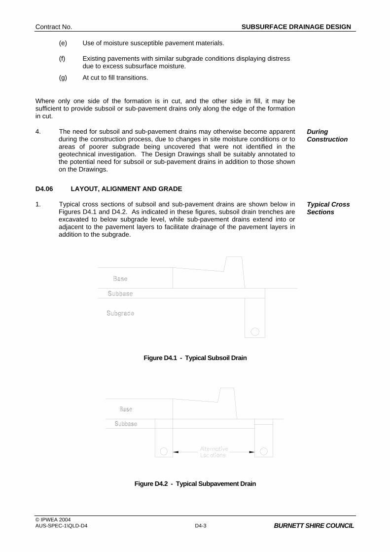
Contract No. SUBSURFACE DRAINAGE DESIGN
© IPWEA 2004 AUS-SPEC-1\QLD-D4 D4-3 BURNETT SHIRE COUNCIL
(e) Use of moisture susceptible pavement materials.
(f) Existing pavements with similar subgrade conditions displaying distress due to excess subsurface moisture.
(g) At cut to fill transitions.
Where only one side of the formation is in cut, and the other side in fill, it may be sufficient to provide subsoil or sub-pavement drains only along the edge of the formation in cut.
4. The need for subsoil and sub-pavement drains may otherwise become apparent during the construction process, due to changes in site moisture conditions or to areas of poorer subgrade being uncovered that were not identified in the geotechnical investigation. The Design Drawings shall be suitably annotated to the potential need for subsoil or sub-pavement drains in addition to those shown on the Drawings.
During Construction
D4.06 LAYOUT, ALIGNMENT AND GRADE
1. Typical cross sections of subsoil and sub-pavement drains are shown below in Figures D4.1 and D4.2. As indicated in these figures, subsoil drain trenches are excavated to below subgrade level, while sub-pavement drains extend into or adjacent to the pavement layers to facilitate drainage of the pavement layers in addition to the subgrade.
Typical Cross Sections
Figure D4.1 - Typical Subsoil Drain
Figure D4.2 - Typical Subpavement Drain

SUBSURFACE DRAINAGE DESIGN Contract No.
© IPWEA 2004 D4-4 AUS-SPEC-1\QLD-D4 BURNETT SHIRE COUNCIL
2. In kerbed roads, the two acceptable alternative locations for the line of the trench are directly behind the kerbline. Pavement layers must extend to at least the line of the rear of the trench.
Kerbed Roads
3. In unkerbed roads, subsoil and sub-pavement drains shall be located within the shoulder, preferably at the edge of the pavement layers as shown in Figure D4.2.
Unkerbed Roads
4. The minimum desirable longitudinal design grade shall be 1.0%. For non corrugated pipes, an absolute minimum grade of 0.5% is acceptable.
Grade
5. Trench widths shall be a minimum of 300mm, with a minimum depth below finished subgrade level of 600mm in earth and 450mm in rock, and below the invert level of any service crossings.
Trench Dimensions
6. Outlets shall be spaced at maximum intervals of 150 metres into gully pits or outlet headwalls. As a salinity prevention measure and where practical, discharge shall be on the downhill side of the embankment or in the cut-fill area so as to reduce the risk of recharge to the subsurface water table. Unless otherwise authorised, where subsurface drains outlet through fill batters, unslotted plastic pipe of the same diameter as the main run shall be specified. A small precast concrete headwall shall be installed at the drain outlet with a marker post to assist maintenance and protect the end of the pipe.
Outlets, Salinity Prevention
7. Cleanouts are to be provided at the commencement of each run of drain, and at intervals not exceeding 80 metres. Cleanouts shall generally be located directly at the rear of kerb or at the edge of shoulder, as applicable.
Cleanouts
8. In salinity affected areas, the Designer should consider providing a separate drainage system for subsurface drains to discharge to a basin where controlled release or desiccation treatment and removal can be facilitated as a maintenance operation. Saline subsurface drainage should not be routinely discharged directly into natural watercourses. Reference to water quality targets for downstream watercourses is essential and the Designer shall provide advice on discharge operations and maintenance compatible with water quality targets and the requirements of the relevant land and water resource authority.
Salinity Prevention
FOUNDATION DRAINS
D4.07 WARRANTS FOR USE
1. Foundation drains are designed to drain excessive ground water areas within the foundation of an embankment or the base of cutting, or to intercept water from entering these areas.
Foundation Drains
2. The need to provide foundation drains may be apparent from the results of the geotechnical survey along the proposed road formation alignment, and in this case the location shall be shown on the Drawings. However, more commonly, the need to provide foundation drains is determined during construction, and hence in this situation requirements and locations cannot be ascertained at the design stage.
Geotechnical Survey During Construction
3. Where the road formation traverses known swampy, flood-prone, salt affected areas or watercharged strata, the Drawings shall be suitable annotated to the potential need for foundation drains at various locations, in addition to those shown on the Drawings.
Need for Additional Drains

Contract No. SUBSURFACE DRAINAGE DESIGN
© IPWEA 2004 AUS-SPEC-1\QLD-D4 D4-5 BURNETT SHIRE COUNCIL
D4.08 LAYOUT, ALIGNMENT AND GRADE
1. Typical cross-sections of foundation drains are shown below in Figure D4.3. Typical Cross Section
Figure D4.3 - Foundation Drains
2. The minimum desirable design grade shall be 1.0%. For non corrugated pipes an absolute minimum grade of 0.5% is acceptable.
Grade
3. Foundation drains shall be a minimum trench width of 300mm, with a variable trench depth to suit the application and ground conditions on site.
Trench Dimensions
4. Outlets shall be spaced at maximum intervals of 150 metres. Outlets
5. Where practicable, cleanouts are to be provided at the commencement of each run of foundation drain and at intervals not exceeding 80 metres. Where not practicable to provide intermediate cleanouts, outlets shall be spaced at maximum intervals of 100 metres.
Cleanouts
DRAINAGE MATS (BLANKETS)
D4.09 WARRANTS FOR USE
1. Type A drainage mats are designed where there is a need to ensure continuity of a sheet flow of water under fills, to collect surface seepage from a wet seepage area, or for protection of vegetation or habitat downstream of the road reserve where a fill would otherwise cut the flow of water. Type A drainage mats are constructed after the site has been cleared and grubbed and before commencement of embankment construction.
Type A Mats
2. Type B drainage mats are designed where there is a need to intercept water which would otherwise enter pavements by capillary action or by other means on fills and to intercept and control seepage water and springs in the floors of cuttings. Type B drainage mats shall be constructed after completion of the subgrade construction and before construction of the pavement.
Type B Mats
3. The need to design for the provision of drainage mats should be apparent from the result of the geotechnical survey along the proposed road formation alignment.
Geotechnical Survey
SUBSURFACE DRAINAGE DESIGN Contract No.
© IPWEA 2004 D4-6 AUS-SPEC-1\QLD-D4 BURNETT SHIRE COUNCIL
MATERIALS
D4.10 SUBSOIL AND SUB-PAVEMENT DRAIN PIPE
1. Pipes designated for subsoil, foundation and sub-pavement drains shall be 100mm dia. slotted pipe.
2. Corrugated plastic pipe shall conform with the requirements of AS2439.1. The appropriate class of pipe shall be selected on the basis of expected live loading at the surface. Joints, couplings, elbows, tees and caps shall also comply with AS2439.1.
3. Slotted rigid UPVC pipe shall be of a type and class approved by Council.
4. All pipe shall be slotted, and fitted with a suitable geotextile filter tube, except for cleanouts and outlets through fill batters which shall be unslotted pipe.
D4.11 INTRA PAVEMENT DRAIN PIPE
1. Pipes designated for intra pavement drains with crushed rock subbases having layer thicknesses neither less than 150mm nor more than 200mm shall be slotted thick walled UPVC pressure pipe complying with AS/NZS 1477.
2. Pipes designated for intra pavement drains with crushed rock subbases having layer thicknesses exceeding 200mm shall be slotted pipe of a type and class approved by Council.
3. Pipes for use in Type B drainage mats shall be slotted thick walled UPVC pressure pipe complying with AS/NZS 1477.
D4.12 FILTER MATERIAL
1. The types of filter material covered by this Specification shall include:
(a) Type A filter material for use in subsoil, foundation, and sub-pavement (trench) drains and for Type B drainage mats.
(b) Type B filter material for use in subsoil, foundation and sub-pavement (trench) drains.
(c) Type C filter material comprising crushed rock for use in Type A drainage mats.
(d) Type D filter material comprising uncrushed river gravel for use in Type A drainage mats.
2. Material requirements and gradings for each type of filter material are included in the Construction Specification, SUBSURFACE DRAINAGE GENERAL.
Contract No. SUBSURFACE DRAINAGE DESIGN
© IPWEA 2004 AUS-SPEC-1\QLD-D4 D4-7 BURNETT SHIRE COUNCIL
3. The type of filter material specified to backfill the sub-surface drainage trenches (subsoil, foundation and sub-pavement drains) shall depend on the permeability of the pavement layers and/or subgrade and the expected flow rate. Generally, Type A filter material is used for the drainage of highly permeable subgrade or pavement layers such as crushed rock or coarse sands, while Type B filter material is used for the drainage of subgrade and pavement layers of lower permeability such as clays, silts or dense graded gravels. Further guidance to the selection of appropriate filter material is contained in ARRB Special Report 35.
Note to Compiler :- Due regard may be taken of the opportunity to use recycled materials for backfill of table drains –( RESOURCE NSW - Specification for Supply of Recycled Materials for Pavements, Earthworks and Drainage, 2003.) Note- disclaimer in front cover of specification under “important” re liability.
D4.13 GEOTEXTILE
1. To provide separation (ie. prevent infiltration of fines) between the filter material in the trench and the subgrade or pavement material, geotextile shall be designated to encapsulate the filter material. The geotextile shall comply with the requirements included in the Construction Specification, SUBSURFACE DRAINAGE GENERAL.
2. Geotextile shall also be designated for both Type A and Type B Drainage Mats.
DOCUMENTATION
D4.14 DRAWINGS AND CALCULATIONS
1. The proposed location of all subsurface drains shall be clearly indicated on the Drawings, including the nominal depth and width of the trench, and the location with respect to the line of the kerb/gutter or edge of pavement. The location of outlets and cleanouts shall also be indicated on the Drawings.
2. Assumptions and/or calculations made in the determination of the need or otherwise for subsurface drainage in special circumstances or as a variation to the requirements of this Specification shall be submitted to Council for approval with the Drawings.
SPECIAL REQUIREMENTS
D4.15 RESERVED
D4.16 RESERVED
D4.17 RESERVED
D4.18 RESERVED


Contract No. STORMWATER DRAINAGE DESIGN
© IPWEA 2004 AUS-SPEC-1\QLD-D5 BURNETT SHIRE COUNCIL
QUEENSLAND
DEVELOPMENT DESIGN SPECIFICATION
D5
STORMWATER
DRAINAGE DESIGN

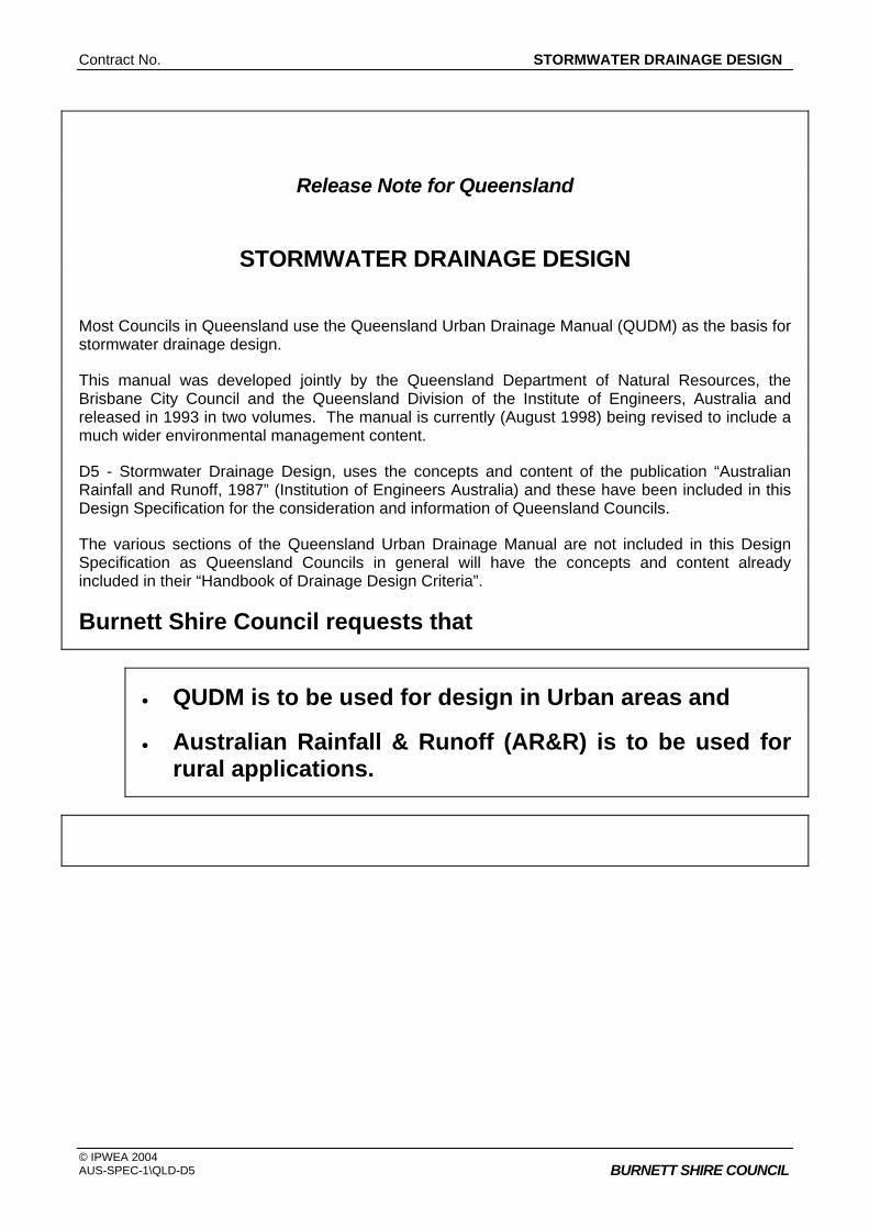
Contract No. STORMWATER DRAINAGE DESIGN
© IPWEA 2004 AUS-SPEC-1\QLD-D5 BURNETT SHIRE COUNCIL
Release Note for Queensland
STORMWATER DRAINAGE DESIGN
Most Councils in Queensland use the Queensland Urban Drainage Manual (QUDM) as the basis for stormwater drainage design.
This manual was developed jointly by the Queensland Department of Natural Resources, the Brisbane City Council and the Queensland Division of the Institute of Engineers, Australia and released in 1993 in two volumes. The manual is currently (August 1998) being revised to include a much wider environmental management content.
D5 - Stormwater Drainage Design, uses the concepts and content of the publication “Australian Rainfall and Runoff, 1987” (Institution of Engineers Australia) and these have been included in this Design Specification for the consideration and information of Queensland Councils.
The various sections of the Queensland Urban Drainage Manual are not included in this Design Specification as Queensland Councils in general will have the concepts and content already included in their “Handbook of Drainage Design Criteria”.
Burnett Shire Council requests that
• QUDM is to be used for design in Urban areas and
• Australian Rainfall & Runoff (AR&R) is to be used for rural applications.
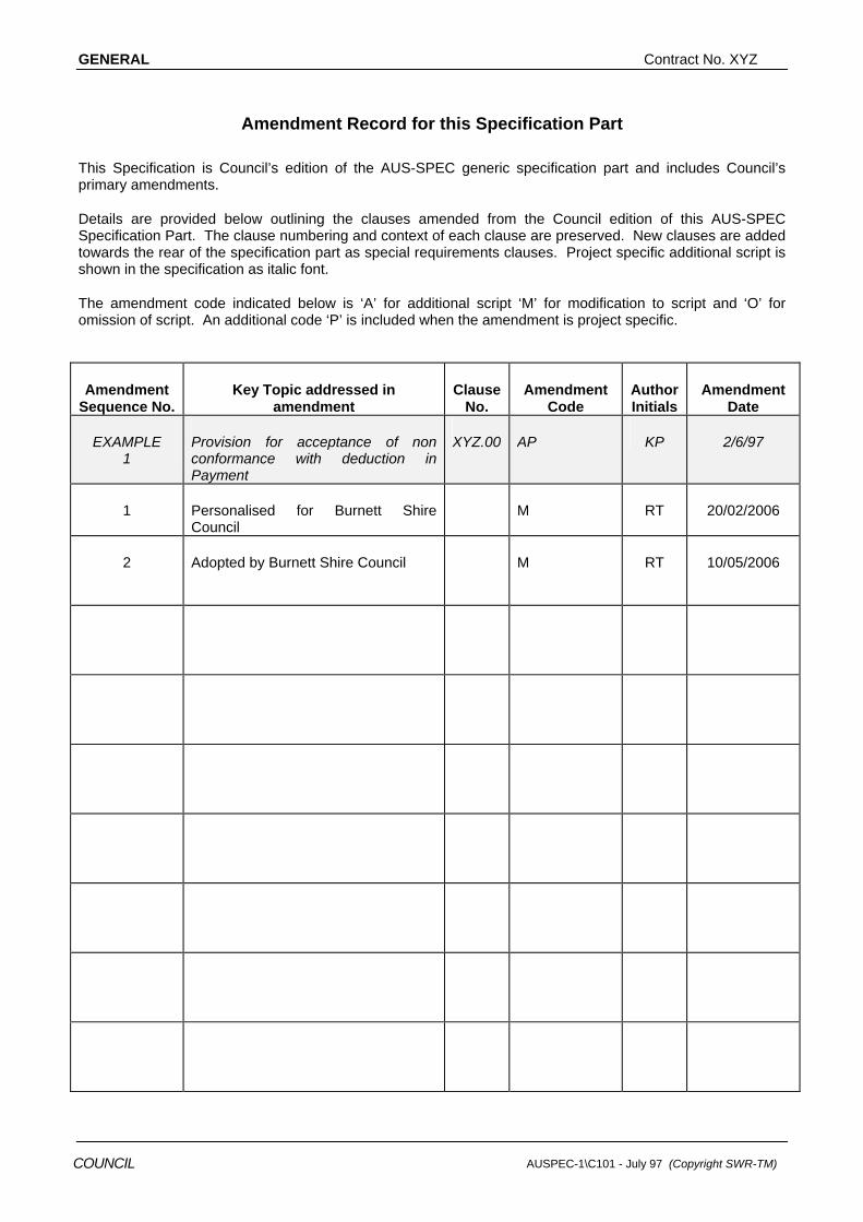
GENERAL Contract No. XYZ
AUSPEC-1\C101 - July 97 (Copyright SWR-TM) COUNCIL
Amendment Record for this Specification Part
This Specification is Council’s edition of the AUS-SPEC generic specification part and includes Council’s primary amendments.
Details are provided below outlining the clauses amended from the Council edition of this AUS-SPEC Specification Part. The clause numbering and context of each clause are preserved. New clauses are added towards the rear of the specification part as special requirements clauses. Project specific additional script is shown in the specification as italic font.
The amendment code indicated below is ‘A’ for additional script ‘M’ for modification to script and ‘O’ for omission of script. An additional code ‘P’ is included when the amendment is project specific.
Amendment Sequence No.
Key Topic addressed in amendment
Clause No.
Amendment Code
Author Initials
Amendment Date
EXAMPLE 1
Provision for acceptance of non conformance with deduction in Payment
XYZ.00 AP KP 2/6/97
1 Personalised for Burnett Shire Council
M RT 20/02/2006
2 Adopted by Burnett Shire Council
M RT 10/05/2006
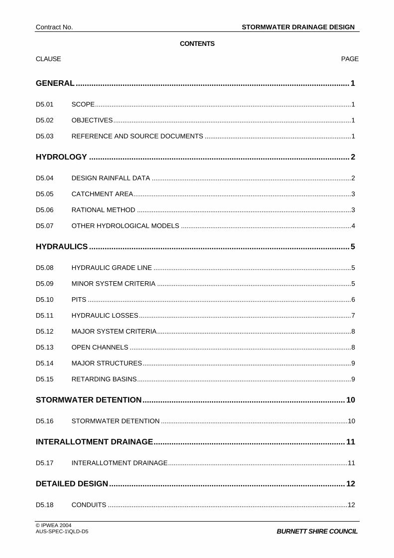
Contract No. STORMWATER DRAINAGE DESIGN
© IPWEA 2004 AUS-SPEC-1\QLD-D5 BURNETT SHIRE COUNCIL
CONTENTS CLAUSE PAGE
GENERAL ........................................................................................................................... 1
D5.01 SCOPE............................................................................................................................................1
D5.02 OBJECTIVES..................................................................................................................................1
D5.03 REFERENCE AND SOURCE DOCUMENTS ................................................................................1
HYDROLOGY ..................................................................................................................... 2
D5.04 DESIGN RAINFALL DATA .............................................................................................................2
D5.05 CATCHMENT AREA.......................................................................................................................3
D5.06 RATIONAL METHOD .....................................................................................................................3
D5.07 OTHER HYDROLOGICAL MODELS .............................................................................................4
HYDRAULICS ..................................................................................................................... 5
D5.08 HYDRAULIC GRADE LINE ............................................................................................................5
D5.09 MINOR SYSTEM CRITERIA ..........................................................................................................5
D5.10 PITS ................................................................................................................................................6
D5.11 HYDRAULIC LOSSES....................................................................................................................7
D5.12 MAJOR SYSTEM CRITERIA..........................................................................................................8
D5.13 OPEN CHANNELS .........................................................................................................................8
D5.14 MAJOR STRUCTURES..................................................................................................................9
D5.15 RETARDING BASINS.....................................................................................................................9
STORMWATER DETENTION........................................................................................... 10
D5.16 STORMWATER DETENTION ......................................................................................................10
INTERALLOTMENT DRAINAGE...................................................................................... 11
D5.17 INTERALLOTMENT DRAINAGE..................................................................................................11
DETAILED DESIGN.......................................................................................................... 12
D5.18 CONDUITS ...................................................................................................................................12

GENERAL Contract No. XYZ
© IPWEA 2004 D5-2 AUS-SPEC-1\QLD-D5 BURNETT SHIRE COUNCIL
D5.19 PIT DESIGN..................................................................................................................................12
D5.20 STORMWATER DISCHARGE......................................................................................................12
D5.21 TRENCH SUBSOIL DRAINAGE...................................................................................................13
DOCUMENTATION........................................................................................................... 13
D5.22 DRAWINGS ..................................................................................................................................13
D5.23 EASEMENTS AND AGREEMENTS.............................................................................................14
D5.24 SUMMARY SHEETS ....................................................................................................................14
D5.25 COMPUTER PROGRAM FILES AND PROGRAM OUTPUT ......................................................14
SPECIAL REQUIREMENTS ............................................................................................. 14
D5.26 RESERVED ..................................................................................................................................14
D5.27 RESERVED ..................................................................................................................................14
D5.28 RESERVED ..................................................................................................................................14

Contract No. STORMWATER DRAINAGE DESIGN
© IPWEA 2004 AUS-SPEC-1\QLD-D5 D5-1 BURNETT SHIRE COUNCIL
DEVELOPMENT DESIGN SPECIFICATION D5 STORMWATER DRAINAGE DESIGN
GENERAL
D5.01 SCOPE
1. The work to be executed under this Specification consists of the design of stormwater drainage systems for urban and rural areas.
D5.02 OBJECTIVES
1. The objectives of stormwater drainage design are as follows:
(a) To ensure that inundation of private and public buildings located in flood-prone areas occurs only on rare occasions and that, in such events, surface flow routes convey floodwaters below the prescribed velocity/depth limits.
(b) To provide convenience and safety for pedestrians and traffic in frequent stormwater flows by controlling those flows within prescribed limits.
(c) Retain within each catchment as much incident rainfall and runoff as is possible and appropriate for the planned use and the characteristics of the catchment.
2. In pursuit of these objectives, the following principles shall apply:
(a) New Developments are to provide a stormwater drainage system in accordance with the "major/minor" system concept set out in Chapter 14 of Australian Rainfall & Runoff, 1987 (AR&R); that is, the "major" system shall provide safe, well-defined overland flow paths for rare and extreme storm runoff events while the "minor" system shall be capable of carrying and controlling flows from frequent runoff events.
Design Principles
(b) Redevelopment - Where the proposed development replaces an existing development, the on-site drainage system is to be designed in such a way that the estimated peak flow rate from the site for the design average recurrence interval (ARI) of the receiving minor system is no greater than that which would be expected from the existing development.
D5.03 REFERENCE AND SOURCE DOCUMENTS
(a) Council Specifications C220 - Stormwater Drainage - General C221 - Pipe Drainage C222 - Precast Box Culverts C223 - Drainage Structures C224 - Open Drains including Kerb & Gutter

GENERAL Contract No. XYZ
© IPWEA 2004 D5-2 AUS-SPEC-1\QLD-D5
BURNETT SHIRE COUNCIL
(b) Australian Standards AS 1254 - Unplasticised PVC (uPVC) pipes and fittings for stormwater
or surface water applications AS 2032 - Code of practice for installation of uPVC pipe systems AS/NZS 2566.1 - Buried flexible pipelines, structural design AS 3725 - Loads on buried concrete pipes AS 4058 - Precast concrete pipes AS 4139 - Fibre reinforced concrete pipes and fittings
(c) QLD State Authorities Department of Natural Resources (jointly with Brisbane City Council & IMEAQ). - Queensland Urban Drainage Manual (QUDM), Volumes 1 &
2, 1993.
(d) Other AUSTROADS - Bridge Design Code. Inst. of Eng. - Australian Rainfall and Runoff (AR&R). A guide to flood
estimation. 2001. Institute of Municipal Engineering Australia, QLD Division. - Standard Drawings, 1997 Sangster, WM., Wood, HW., Smerdon, ET., and Bossy, HG. - Pressure Changes at Storm Drain Junction, Engineering
Series, Bulletin No. 41, Eng. Experiment Station, Univ. of Missouri 1958.
Hare CM. - Magnitude of Hydraulic Losses at Junctions in Piped
Drainage Systems. Transactions, Inst. of Eng. Aust., Feb. 1983.
Concrete Pipe Association of Australia - Concrete Pipe Guide, charts for the selection of concrete
pipes to suit varying conditions. Henderson, FM. Open Channel Flow, 1966. Chow, Ven Te - Open Channel Hydraulics, 1959. John Argue - Australian Road Research Board Special Report 34 - Stormwater drainage design in small urban catchments: a
handbook for Australian practice. Australian National Conference On Large Dams, Leederville WA.
- ANCOLD 1986, Guidelines on Design Floods for Dams. Manufacturers Specification
HYDROLOGY
D5.04 DESIGN RAINFALL DATA
1. Design Intensity-Frequency-Duration (IFD) Rainfall - IFD relationships shall be derived in accordance with Volume 1, Chapter 2, of AR&R, for the particular catchment under consideration.
I-F-D Relationships

Contract No. STORMWATER DRAINAGE DESIGN
© IPWEA 2004 AUS-SPEC-1\QLD-D5 D5-3 BURNETT SHIRE COUNCIL
2. The nine basic parameters read from Maps 1-9 in Volume 2 of AR&R shall be shown in the calculations submitted to Council, except where the Bureau of Meteorology provides a polynomial relationship for the catchment.
3. Where design IFD rainfalls are provided for specific locations these are provided in ARI.
4. Design Average Recurrence Interval (ARI) - For design under the "major/minor" concept, the design ARI’s to be used are given below.
Average Recurrence Intervals
5. Recurrence intervals for minor events depends on the zoning of the land being serviced by the drainage system. The minor system design ARIs are detailed below:-
• 10 years for commercial and central Business area "minor" systems
• 10 years for urban residual and high density systems • 2 years for residential area "minor" systems • 2 years for rural residential area "minor" systems • 1 year for parks and recreation area "minor" systems.
6. In addition, where a development is designed in such a way that the major system flows involve surcharge across private property, then the underground system (both pipes and inlets) shall be designed to permit flows into and contain flows having an ARI of 100 years from the upstream catchment which would otherwise flow across the property. A surcharge path shall be defined for systems even where 100 year ARI flows can be maintained within the system. Easements are to be provided in private property over pipe systems and surcharge paths.
Easements in Private Property
D5.05 CATCHMENT AREA
1. The catchment area of any point is defined by the limits from where surface runoff will make its way, either by natural or man made paths, to this point. Consideration shall be given to likely changes to individual catchment areas due to the full development of the catchment.
Catchment Definition
2. Where no detailed survey of the catchment is available, 1:25000 topographic maps or 1:2500 orthophoto maps are to be used to determine the catchments and to measure areas.
3. Catchment area land use shall be based on current available zoning information or proposed future zonings, where applicable.
D5.06 RATIONAL METHOD
1. Rational Method calculations to determine peak flows shall be carried out in accordance with Volume 1, Chapter 14, AR&R and the requirements of this Specification.
2. All calculations shall be carried out by a qualified person experienced in hydrologic and hydraulic design.
Qualified Person
3. Co-efficients of Run-off shall be calculated as per Book 8 of AR&R and full details of co-efficients utilised shall be provided.
Runoff Co-efficients
4. Details of percentage impervious and Co-efficients of Run-off for specific locations and for individual zonings are given in QUDM. These can be used in lieu of more detailed calculations.

GENERAL Contract No. XYZ
© IPWEA 2004 D5-4 AUS-SPEC-1\QLD-D5
BURNETT SHIRE COUNCIL
5. The time of concentration of a catchment is defined as the time required for storm runoff to flow from the most remote point on the catchment to the outlet of the catchment.
Times of Concentration
6. Where the flow path is through areas having different flow characteristics or includes property and roadway, then the flow time of each portion of the flow path shall be calculated separately.
Different Flow Characteristics
7. The maximum time of concentration in an urban area shall be in accordance with QUDM “Standard Inlet Times” unless sufficient evidence is provided to justify a greater time.
8. Flow paths to pits shall be representative of the fully developed catchment considering such things as fencing and the likely locations of buildings and shall be shown for each collection pit on the catchment area plan. Consideration shall be given to likely changes to individual flow paths due to the full development of the catchment.
Flow Paths to Pits
9. Surface roughness co-efficients "n" shall generally be derived from information in Book 8 of AR&R.
Overland Flow Retardance
D5.07 OTHER HYDROLOGICAL MODELS
1. Other hydrological models may be used as long as the requirements of AR&R are met, summaries of calculations are provided and details are given of all program input and output.
Alternative Models
2. Where computer analysis programs are used, copies of the final data files shall be provided on submission of the design to Council and with the final drawings after approval by Council.
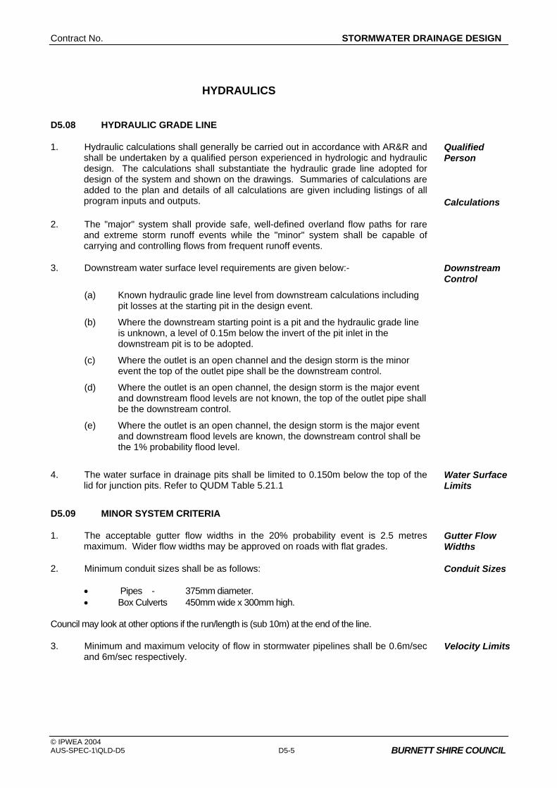
Contract No. STORMWATER DRAINAGE DESIGN
© IPWEA 2004 AUS-SPEC-1\QLD-D5 D5-5 BURNETT SHIRE COUNCIL
HYDRAULICS
D5.08 HYDRAULIC GRADE LINE
1. Hydraulic calculations shall generally be carried out in accordance with AR&R and shall be undertaken by a qualified person experienced in hydrologic and hydraulic design. The calculations shall substantiate the hydraulic grade line adopted for design of the system and shown on the drawings. Summaries of calculations are added to the plan and details of all calculations are given including listings of all program inputs and outputs.
Qualified Person
Calculations
2. The "major" system shall provide safe, well-defined overland flow paths for rare and extreme storm runoff events while the "minor" system shall be capable of carrying and controlling flows from frequent runoff events.
3. Downstream water surface level requirements are given below:-
(a) Known hydraulic grade line level from downstream calculations including pit losses at the starting pit in the design event.
Downstream Control
(b) Where the downstream starting point is a pit and the hydraulic grade line is unknown, a level of 0.15m below the invert of the pit inlet in the downstream pit is to be adopted.
(c) Where the outlet is an open channel and the design storm is the minor event the top of the outlet pipe shall be the downstream control.
(d) Where the outlet is an open channel, the design storm is the major event and downstream flood levels are not known, the top of the outlet pipe shall be the downstream control.
(e) Where the outlet is an open channel, the design storm is the major event and downstream flood levels are known, the downstream control shall be the 1% probability flood level.
4. The water surface in drainage pits shall be limited to 0.150m below the top of the lid for junction pits. Refer to QUDM Table 5.21.1
Water Surface Limits
D5.09 MINOR SYSTEM CRITERIA
1. The acceptable gutter flow widths in the 20% probability event is 2.5 metres maximum. Wider flow widths may be approved on roads with flat grades.
Gutter Flow Widths
2. Minimum conduit sizes shall be as follows: • Pipes - 375mm diameter. • Box Culverts 450mm wide x 300mm high. Council may look at other options if the run/length is (sub 10m) at the end of the line.
Conduit Sizes
3. Minimum and maximum velocity of flow in stormwater pipelines shall be 0.6m/sec and 6m/sec respectively.
Velocity Limits

GENERAL Contract No. XYZ
© IPWEA 2004 D5-6 AUS-SPEC-1\QLD-D5
BURNETT SHIRE COUNCIL
D5.10 PITS
1. Inlet Pits shall be spaced so that the gutter flow width is limited in accordance with this Specification and so that the inlet efficiency is not affected by adjacent inlet openings. Preference shall be given to the location of drainage pits at the upstream side of allotments.
Spacing
2. Other pits shall be provided: • To enable access for maintenance. • At changes in direction, grade, level or class of pipe. • At junctions.
3. The maximum recommended spacing of pits where flow widths are not critical are given in Table D5.1 below:
Pipe Size (mm) Spacing (m)
Generally less than 1200 100
1200 or larger 150
In tidal influence all 100
Table D5.1 - Pit Spacing
4. Kerb inlet lengths to side entry pits are to be a preferred maximum of 3.0m, with an absolute maximum of 5.0m where the grade is 10% or more, and an absolute maximum of 4.0m where the grade is less than 10%.
Inlet Capacity
5. Information on pit capacities is available in the following sources:-
• Manufacturers Specifications.
• Queensland Urban Drainage Manual.
• Pit relationships given in Book 8 of AR&R.
6. None of these pit charts include any blockage factors. The percentage of theoretical capacity allowed in relation to type of pit is given in Table D5.2 below:-
Allowance for Inlet Blockage
Condition Inlet Type Percentage of Theoretical Capacity Allowed
Sag Side entry 80%
Sag Grated 50%
Sag Combination Side inlet capacity only Grate assumed completely blocked
Sag "Letterbox" 50%
Continuous Grade Side entry 80%
Continuous Grade Grated 50%
Continuous Grade Combination 90%
Table D5.2 - Allowable Pit Capacities

Contract No. STORMWATER DRAINAGE DESIGN
© IPWEA 2004 AUS-SPEC-1\QLD-D5 D5-7 BURNETT SHIRE COUNCIL
D5.11 HYDRAULIC LOSSES
1. The pressure change co-efficient "Ke" shall be determined from the appropriate charts given in QUDM.
Pit Losses
2. Allowable reduction in "Ke" due to benching is given in QUDM.
3. Computer program default pressure change co-efficient "Ke" shall not be acceptable unless they are consistent with those from the charts in QUDM. The chart used and relevant co-efficients for determining "Ke" value from that chart shall be noted on the hydraulic summary sheet provided for plan checking and included on the final design drawings.
4. Bends may be permissible in certain circumstances and discussions with Council regarding their use is required prior to detailed design. Appropriate values of pit pressure change co-efficient at bends are given in QUDM.
Bend Losses
5. Where possible design should try to avoid clashes between services. However, where unavoidable clashes occur with existing sewer mains then the pressure change co-efficient Kp shall be determined from the chart given in QUDM.
Service Entry Losses
6. Requirements for private pipes entering Council's system are given below:- (a) All pipe inlets, including roof and subsoil pipes, shall where possible,
enter the main pipe system at junction pits. These shall be finished off flush with and be grouted into the pit wall.
(b) If a junction has to be added which is larger than 225mm then a junction pit shall be built at this location in accordance with this Specification.
(c) For smaller inlets, the drainage pipes may be broken into to allow interconnection with the main line. In this case the sideline shall be finished flush with and be grouted into the main line.
7. Construction of a junction without a structure should be avoided where possible. Permission to do this is required by Council prior to detailed design. Where this is unavoidable the pressure change co-efficients Ku, for the upstream pipe and Kl, for the lateral pipe, shall be determined from the chart given in QUDM.
Pipe Junction Losses
8. Going from larger upstream to smaller downstream conduits is not permitted without approval of Council prior to detailed design. In going from smaller to larger pipes benching shall be provided in pits to enable a smooth flow transition. Losses in sudden expansions and contractions are given in QUDM.
Contraction/ Expansion Losses
9. Drainage pipe systems shall be designed as an overall system, with due regard to the upstream and downstream system and not as individual pipe lengths. Drainage pipeline systems shall generally be designed as gravity systems flowing full at design discharge, but may be pressurised with the use of appropriate pits and joints. Pipe friction losses and pipe sizes in relation to discharge shall be determined using the Colebrook-White formula with the acceptable roughness co-efficients being 0.15mm for concrete pipes and 0.15mm for FRC pipes.
Pipe Friction Losses

GENERAL Contract No. XYZ
© IPWEA 2004 D5-8 AUS-SPEC-1\QLD-D5
BURNETT SHIRE COUNCIL
D5.12 MAJOR SYSTEM CRITERIA
1. Refer to QUDM Design
D5.13 OPEN CHANNELS
1. Generally, open channels will only be permitted where they form part of the trunk drainage system and shall be designed to have smooth transitions with adequate access provisions for maintenance and cleaning. Where Council permits the use of an open channel to convey flows from a development site to the receiving water body, such a channel shall comply with the requirements of this Specification.
Safety
2. Design of open channels shall be in accordance with Volume 1, Chapter 14, of AR&R. Open channels will be designed to contain the major system flow less any flow that is contained in the minor system, with an appropriate allowance for blockage of the minor system.
3. Friction losses in open channels shall be determined using Mannings "n" values given below:-
Mannings "n" Roughness Co-efficients for open channels shall generally be derived from information in Chapter 14 of AR&R. Mannings "n" values applicable to specific channel types are given below:-
Concrete Pipes or Box Sections 0.011 Concrete (trowel finish) 0.014 Concrete (formed without finishing) 0.016 Sprayed Concrete (gunite) 0.018 Bitumen Seal 0.018 Bricks or pavers 0.015 Pitchers or dressed stone on mortar 0.016 Rubble Masonry or Random stone in mortar 0.028 Rock Lining or Rip-Rap 0.028 Corrugated Metal 0.027 Earth (clear) 0.022 Earth (with weeds and gravel) 0.028 Rock Cut 0.038 Short Grass 0.033 Long Grass 0.043
Channel Roughness
4. Where the product of average Velocity and average flow Depth for the design flow rate is greater than 0.4m2/s, the design will be required to specifically provide for the safety of persons who may enter the channel in accordance with Volume 1, Chapter 14, of AR&R.
5. Maximum side slopes on grassed lined open channels shall be 1 in 4, with a preference given to 1 in 6 side slopes, channel inverts shall generally have minimum cross slopes of 1 in 20.
Side Slopes
6. Low flow provisions in open channels (man-made or altered channels) will require low flows to be contained within a pipe system or concrete lined channel section at the invert of the main channel. Subsurface drainage shall be provided in grass lined channels to prevent waterlogging of the channel bed. The width of the concrete lined channel section shall be the width of the drain invert or at least sufficiently wide enough to accommodate the full width of a tractor.
Low Flows

Contract No. STORMWATER DRAINAGE DESIGN
© IPWEA 2004 AUS-SPEC-1\QLD-D5 D5-9 BURNETT SHIRE COUNCIL
7. Transition in channel slopes to be designed to avoid or accommodate any hydraulic jumps due to the nature of the transition.
Hydraulic Jumps
D5.14 MAJOR STRUCTURES
Burnett Shire Definition for major structures are • Bridge is a structure that has a span > 3 metres • Culvert is a structure that has a span > 1500 or 600mm high
1. All major structures in urban areas, including bridges and culverts, shall be designed for the 100 year ARI storm event without afflux. Some afflux and upstream inundation may be permitted in certain rural and urban areas provided the increased upstream flooding is minimal and does not inundate private property.
Afflux
2. A minimum clearance of 0.3m between the 100 year ARI flood level and the underside of any major structure superstructure is required to allow for passage of debris without blockage.
Freeboard
3. Certified structural design shall be required on bridges and other major culvert structures and may be required on some specialised structures.
4. Culverts (either pipe or box section) shall be designed in accordance with charts provided in Austrailian Rainfall and Runoff (AR&R) Drainage Design Criteria, with due regard being given to inlet and exit losses, inlet and outlet control and scour protection.
Culverts
D5.15 RETARDING BASINS
1. For each ARI a range of storm events shall be run to determine the peak flood level and discharge from the retarding basin. Storm patterns shall be those given in Volume 1, Chapter 11 of AR&R. Sensitivity to storm pattern should be checked by reversing these storm patterns.
Critical Storm Duration
2. The critical storm duration with the retarding basin is likely to be longer than without the basin. A graph showing the range of peak flood levels in the basin and peak discharges from the basin shall be provided for the storms examined.
3. Flood Routing should be modelled by methods outlined in AR&R. Routing
4. The high level outlet to any retarding basin shall have capacity to contain a minimum of the 100 year ARI flood event. Additional spillway capacity may be required due to the hazard category of the structure. The hazard category should be determined by reference to ANCOLD.
High Level Outlet
5. The spillway design shall generally be in accordance with the requirements for Open Channel Design in this Specification.
6. Wherever practicable and certainly in areas known to be affected by high water tables and/or salinity of groundwater, retarding basins shall be designed to be water retentive so that surface drainage water does not leak to the subsurface, recharging groundwater.
Salinity Prevention
7. Pipe systems shall contain the minor flow through the Retarding Basin wall. Outlet pipes shall be rubber ring jointed with lifting holes securely sealed. Pipe and culvert bedding shall be specified to minimise its permeability, and cut off walls and anti seepage collars installed where appropriate.
Low Flow Provision
8. The low flow pipe intake shall be protected to prevent blockages.

GENERAL Contract No. XYZ
© IPWEA 2004 D5-10 AUS-SPEC-1\QLD-D5
BURNETT SHIRE COUNCIL
9. Freeboard - Minimum floor levels of dwelling shall be 0.5m above the 100 year ARI flood level in the basin.
Freeboard at Dwellings
10. Public Safety Issues - Basin design is to consider the following aspects relating to public safety.
Safety Issues
• Side slopes are to be a maximum of 1 in 6 to allow easy egress. Side slopes of greater than 1 in 4 may require handrails to assist in egress.
• Water depths shall be, where possible, less than 1.2m in the 20 year ARI storm event. Where neither practical or economic greater depths may be acceptable. In that case the provision of safety refuge mounds should be considered.
• The depth indicators should be provided indicating maximum depth in the basin.
• Protection of the low flow intake pipe shall be undertaken to reduce hazards for people trapped in the basin.
• Signage of the spillway is necessary to indicate the additional hazard.
• Basins shall be designed so that no ponding of water occurs on to private property or roads.
• No planting of trees in basin walls is allowed.
• No basin spillway is to be located directly upstream of urban areas.
• Submission of Drawings to the Dam Safety Committee is required where any of these guidelines are not met or Council specifically requires such submission.
STORMWATER DETENTION
D5.16 STORMWATER DETENTION
1. Installation of Stormwater Detention is required on redevelopment sites within the City where under capacity drainage systems exist. A redevelopment site is defined as a site which used to have or was originally zoned to have a lower density development than is proposed.
Re-development
2. Location of basins for stormwater detention, stormwater treatment or sedimentation purposes shall avoid areas that are known to be permanent or seasonal groundwater discharge areas. This action reduces the likelihood of recharge into the groundwater.
Salinity Prevention
3. The requirements for Stormwater Detention Design are outlined in QUDM and AR&R.

Contract No. STORMWATER DRAINAGE DESIGN
© IPWEA 2004 AUS-SPEC-1\QLD-D5 D5-11 BURNETT SHIRE COUNCIL
INTERALLOTMENT DRAINAGE
D5.17 INTERALLOTMENT DRAINAGE
1. Interallotment Drainage is to be designed in accordance with QUDM and shall be provided for every allotment which does not drain directly to its frontage street or a natural watercourse.
2. Interallotment drainage shall be contained within an easement not less than 3.0m wide , and the easement shall be in favour of the Burnett Shire Council.
3. Pipe Capacity - The interallotment drain shall be designed to accept concentrated drainage from buildings and paved areas on each allotment for flow rates having a design ARI the same as the "minor" street drainage system.
4. In lieu of more detailed analysis, the following areas of impervious surface are assumed to be contributing runoff to the interallotment drain:-
Development Type % of Lot Area
• Residential (2a) 40 • Residential (2b) 70 • Industrial 80 • Commercial 90
Impervious Area
5. Pipes shall be designed to flow full at the design discharge without surcharging of inspection pits.
6. Interallotment drainage pits shall be located at all changes of direction. Pits shall be constructed of concrete, with 100mm thick walls and floor and have a minimum 600 x 600 internal dimensions. Pits shall be with a 100mm concrete lid finished flush with the surface of works. Depressed grated inlets are acceptable.
Pits
7. Pipes - Minimum Grade - The interallotment drainage shall have a minimum longitudinal gradient of 0.5%.
Grade
8. Interallotment Drainage Pipe Standards - The interallotment drainage shall be constructed from rubber ring jointed pipes of either fibre reinforced concrete drainage pipe, reinforced concrete pipe, or UPVC pipe which shall conform respectively to the requirements of AS 4139, AS 4058 and AS 1254. In public road and recreation reserves where vehicle loads may be encountered, reinforced concrete pipe only, shall be used.
Pipe Type
9. Interallotment Drainage Pipe - Relationship to Sewer Mains - Where interallotment drainage and sewer mains are laid adjacent to each other they are to be spaced 1.5 metres between pipe centrelines (where the pipe inverts are approximately equal).
Sewer
10. Where there is a disparity in level between inverts the spacing is to be submitted for approval.
11. Where sewer mains are in close proximity to interallotment drainage lines they are to be shown on the interallotment drainage plan.

GENERAL Contract No. XYZ
© IPWEA 2004 D5-12 AUS-SPEC-1\QLD-D5
BURNETT SHIRE COUNCIL
DETAILED DESIGN
D5.18 CONDUITS
1. Conduits and materials shall be in accordance with the relevant Australian standards.
Materials
2. Pipe bedding and cover requirements for reinforced and fibre reinforced concrete pipes shall be determined from the Concrete Pipe Association "Concrete Pipe Guide" or AS 3725. For uPVC pipes, the requirements shall be to AS 2032.
Bedding and Cover
3. Conduit jointing shall be in accordance with manufacturer’s specifications. Jointing
4. Drainage lines in road reserves shall generally be located behind the kerb line and parallel to the kerb. Drainage lines in easements shall generally be centrally located within easements.
Location
5. Bulkheads shall be designed on drainage lines where the pipe gradient generally exceeds 5 per cent for pipe sizes above 300mm. The design details shall address the size, and position in the trench as well as spacing along the line.
Bulkheads
D5.19 PIT DESIGN
1. Pits shall be designed with benching to improve hydraulic efficiency and reduce water ponding. Typical pit designs and other pit design requirements are included in QUDM. Safety and safe access are important considerations in pit design. Step irons shall be detailed where required and grates shall be of “bicycle safe” design.
D5.20 STORMWATER DISCHARGE
1. Stormwater discharge shall be located so as to avoid recharging groundwater and creating or worsening salinity degradation of adjacent land. Stormwater discharge shall be located to avoid areas with high groundwater tables, groundwater discharge areas or salt-affected land. The Designer shall meet requirements of the appropriate land and water resources authority with regard to the salinity levels of discharge to natural watercourses.
Salinity Prevention
2. Scour protection at culvert or pipe system outlets shall be constructed in accordance with guidelines set down in QUDM criteria unless outlet conditions dictate the use of more substantial energy dissipation arrangements.
Scour Protection
3. Kerb and gutter shall be extended to drainage pit or natural point of outlet. Where outlet velocity is greater than 2.5m per second or where the kerb and gutter discharge causes scour, then protection shall be provided to prevent scour and dissipate the flow.
Kerb & Gutter Termination
4. At points of discharge of gutters or stormwater drainage lines or at any concentration of stormwater from one or on to adjoining properties, either upstream or downstream, Council will require the Developer to enter into a Deed of Agreement with the adjoining owner(s) granting permission to the discharge of stormwater drainage and the creation of any necessary easements with the cost of the easement being met by the Developer.
Easements, Adjoining Owners
5. Where the drainage is to discharge to an area under the control of another statutory authority , the design requirements of that Statutory Authority are also to be met.
Other Authorities’ Requirements
Contract No. STORMWATER DRAINAGE DESIGN
© IPWEA 2004 AUS-SPEC-1\QLD-D5 D5-13 BURNETT SHIRE COUNCIL
6. The minimum drainage easement width shall be 3.0m for drainage systems to be taken over by Council. The overall width of the easement in Council's favour will be such as to contain the full width of overland flow or open channel flow in the major system design event.
Council Easement
7. Piped stormwater drainage discharging to recreation reserves is to be taken to a natural watercourse and discharged in an approved outlet structure or alternatively taken to the nearest trunk stormwater line.
Recreation Reserves
D5.21 TRENCH SUBSOIL DRAINAGE
1. Subsoil Drainage shall be provided in pipe trenches as follows:
In cases where pipe trenches are backfilled with sand or other pervious material, a 3m length of subsoil drain shall be constructed in the bottom of the trench immediately upstream from each pit or headwall. The subsoil drain shall consist of 100mm diameter agricultural pipes, butt jointed with joints wrapped with hessian, or slotted PVC pipe. The upstream end of the subsoil drain shall be sealed with cement mortar, and the downstream end shall discharge through the wall of the pit or headwall.
DOCUMENTATION
D5.22 DRAWINGS
1. Catchment Area Plans shall be drawn to scales of 1:500, 1:4000 or 1:25000, unless alternative scales are specifically approved by Council and shall show contours, direction of grading of kerb and gutter, general layout of the drainage system with pit locations, catchment limits and any other information necessary for the design of the drainage system.
Catchment Areas
2. The Drainage System Layout Plan shall be drawn to a scale of 1:500 and shall show drainage pipeline location, drainage pit location and number and road centreline chainage, size of opening and any other information necessary for the design and construction of the drainage system.
Drainage System Layout
3. The plan shall also show all drainage easements, reserves and natural watercourses. The plan may be combined with the road layout plan.
4. The Drainage System Longitudinal Section shall be drawn to a scale of 1:500 horizontally and 1:50 vertically and shall show pipe size, class and type, pipe support type in accordance with AS 3725 or AS 2032 as appropriate, pipeline and road chainages, pipeline grade, hydraulic grade line and any other information necessary for the design and construction of the drainage system.
Longitudinal Section
5. Open Channel Cross Sections shall be drawn to a scale of 1:100 natural and shall show the direction in which the cross sections should be viewed. Reduced levels are to be to Australian Height Datum (AHD), unless otherwise approved by Council where AHD is not available. Cross sections may alternatively be provided on floppy disk in HEC2 format as a data input file for the design flow rates.
Open Channels
6. Details including standard and non-standard pits and structures, pit benching, open channel designs and transitions shall be provided on the Drawings to scales appropriate to the type and complexity of the detail being shown.
Details

GENERAL Contract No. XYZ
© IPWEA 2004 D5-14 AUS-SPEC-1\QLD-D5
BURNETT SHIRE COUNCIL
7. As Constructed Drawings shall be submitted to Council upon completion of the drainage construction and prior to the issue of the subdivision certificate. The detailed Drawings may form the basis of this information, however, any changes must be noted on these Drawings.
Work-as- Executed Drawings
8. Digital drawings are to be organized into separate layers for each asset type.
9. When submitting drawings at completion of the project all associated files are to be provided ie Font, X-Ref, VBA, Plot, and other scripts used to produce the drawing. (The use of E-transmit or similar “pack and go” processes will provide all associated files and scripts.)
D5.23 EASEMENTS AND AGREEMENTS
1. Evidence of any Deed of Agreement necessary to be entered into as part of the drainage system will need to be submitted prior to any approval of the engineering Drawings. Easements will need to be created prior to the issue of the subdivision certificate.
2. Where an agreement is reached with adjacent landowners to increase flood levels on their property or otherwise adversely affect their property, a letter signed by all the landowners outlining what they have agreed to and witnessed by an independent person shall be submitted prior to any approval of the engineering Drawings.
D5.24 SUMMARY SHEETS
1. A copy of a Hydrological Summary Sheet providing the minimum information set out in QUDM is required.
Hydrology
2. A copy of a Hydraulic Summary Sheet providing the minimum information set out in QUDM is required.
Hydraulics
D5.25 COMPUTER PROGRAM FILES AND PROGRAM OUTPUT
1. Computer program output may be provided as long as summary sheets for Hydrological and Hydraulic calculations in accordance with this Specification are provided with plans submitted for checking and with final Drawings.
2. Copies of final computer data files, for both hydrological and hydraulic models shall be provided for Council's database of flooding and drainage information in formats previously agreed with Council.
SPECIAL REQUIREMENTS
D5.26 RESERVED
D5.27 RESERVED
D5.28 RESERVED

Contract No. STORMWATER DRAINAGE DESIGN
© IPWEA 2004 AUS-SPEC-1\QLD-D5 BURNETT SHIRE COUNCIL
QUEENSLAND
DEVELOPMENT DESIGN SPECIFICATION
D6
SITE REGRADING


Contract No. SITE REGRADING
© IPWEA 2004 AUS-SPEC-1\QLD-D6 BURNETT SHIRE COUNCIL
Amendment Record for this Specification Part
This Specification is Council’s edition of the AUS-SPEC generic specification part and includes Council’s primary amendments.
Details are provided below outlining the clauses amended from the Council edition of this AUS-SPEC Specification Part. The clause numbering and context of each clause are preserved. New clauses are added towards the rear of the specification part as special requirements clauses. Project specific additional script is shown in the specification as italic font.
The amendment code indicated below is ‘A’ for additional script ‘M’ for modification to script and ‘O’ for omission of script. An additional code ‘P’ is included when the amendment is project specific.
Amendment Sequence No.
Key Topic addressed in amendment
Clause No.
Amendment Code
Author Initials
Amendment Date
EXAMPLE 1
Provision for acceptance of non conformance with deduction in Payment
XYZ.00 AP KP 2/6/97
1 Adopted by Burnett Shire Council
M RT 10/05/2006

Contract No. SITE REGRADING
© IPWEA 2004 AUS-SPEC-1\QLD-D6 BURNETT SHIRE COUNCIL
CONTENTS CLAUSE PAGE
GENERAL ........................................................................................................................... 1
D6.01 SCOPE............................................................................................................................................1
D6.02 OBJECTIVES..................................................................................................................................1
D6.03 REFERENCE AND SOURCE DOCUMENTS ................................................................................1
D6.04 SITE REGRADING CONCEPT.......................................................................................................2
D6.05 SPECIAL TREATMENT OF PARTICULAR AREAS.......................................................................2
D6.06 GENERAL STANDARD OF LOT PREPARATION.........................................................................3
D6.07 STANDARD OF FILL FOR LOTS...................................................................................................4
D6.08 TEMPORARY DIVERSION DRAINS..............................................................................................4
D6.09 CONCURRENCE WITH THE DEPARTMENT OF ENVIRONMENT AND HERITAGE .................4
D6.10 WORK AS EXECUTED DRAWINGS..............................................................................................5
D6.11 CARTAGE OF SOIL........................................................................................................................5
D6.12 EFFECT ON ADJOINING PROPERTIES.......................................................................................5
SPECIAL REQUIREMENTS ............................................................................................... 5
D6.13 RESERVED ....................................................................................................................................5
D6.14 RESERVED ....................................................................................................................................5
D6.15 RESERVED ....................................................................................................................................5


Contract No. SITE REGRADING
© IPWEA 2004 AUS-SPEC-1\QLD-D6 D6-1 BURNETT SHIRE COUNCIL
DEVELOPMENT DESIGN SPECIFICATION D6 - SITE REGRADING
GENERAL
D6.01 SCOPE
1. This Design Specification sets out requirements for the site regrading involved in land development and subdivision. Conceptual requirements are presented as necessary considerations when preparing designs for site regrading.
2. The scope of this Specification assumes that the Designer is familiar with requirements cited in the various construction specifications, specifically those related to earthworks, clearing and grubbing, erosion and sedimentation. Additionally the Designer needs to make reference to the associated design specifications related to stormwater drainage design, geometric road design and erosion control and stormwater management.
Familiarity with other Specifications Required
D6.02 OBJECTIVES
1. This Specification aims to assist the Designer in achieving:
• efficient and economical design
• enhancement of the environmental character of the site whilst maintaining the natural features of the site
Environmen-tally Sound
• provision of safe conditions for construction commensurate with the proposed purpose of the development
Safe for Construction
• equality of building conditions for residential development
• a minimal impact on adjoining properties and developments. Impact on Adjoining Properties
D6.03 REFERENCE AND SOURCE DOCUMENTS
(a) Council Specifications Construction Specifications C211 - Control of Erosion and Sedimentation C212 - Clearing and Grubbing C213 - Earthworks C273 - Landscaping Design Specifications D1 - Geometric Road Design D5 - Stormwater Drainage Design D7 - Erosion Control and Stormwater Management
SITE REGRADING Contract No.
© IPWEA 2004 D6-2 AUS-SPEC-1\QLD-D6 BURNETT SHIRE COUNCIL
(b) Australian Standards AS 3798 - Guidelines on earthworks for commercial and residential
developments AS 2870.1 - Residential slabs and footings - Construction.
D6.04 SITE REGRADING CONCEPT
1. Areas of a site proposed for building or recreational purposes may not be suitable in their natural state for their intended function without improvement works to:
(a) Alleviate flooding of low-lying ground
(b) Fill gullies or create emergency flowpaths after underground stormwater piping has been installed
(c) Allow improved runoff from flat ground
(d) Regrade excessively steep slopes that would preclude economical construction of dwelling foundations
(e) Allow effective recreational use or give reasonable access
The Designer shall review the natural surface contours and where necessary shall design finished surface levels that ensure the land is suitably prepared
2. Where practical, areas should be regraded to minimise the necessity for underground drainage systems with surface inlet pits, and allow surface water to flow naturally to roads or drainage reserves without excessive concentration.
Drainage
3. The Designer shall consider the implications of site regrading in relation to the existing natural environment. Generally site regrading shall be minimised in heavily treed areas.
Natural Environment
4. Care shall be taken to provide depressions for overland flow from low points and over major drainage lines, to direct stormwater for storms up to a 100 year average recurrence interval (ARI).
Overland Flow
5. The design of site regrading areas in conjunction with the design of roadworks shall be considered with the objective of balancing cut to fill and achieving both an economical development and minimising haulage of imported fill or spoil to and from the development site. Bulk haulage should always be considered an adverse effect on adjacent development, and infrastructure.
Minimal Road Haulage
D6.05 SPECIAL TREATMENT OF PARTICULAR AREAS
1. Areas abutting the 100 year ARI flood levels shall be site regraded to a minimum level of 0.3 metres above the 100 year ARI flood levels. In doing so, the Designer shall ensure that other areas are then not affected by flooding. The site shall be identified on the Drawings with appropriate notation of site specific requirements.
Flooding
2. In the event that an area is known to be affected by or inundated by local stormwater flows, the Designer shall investigate the existing conditions as they relate to the proposed development and advise the Developer in the preliminary design report on all data obtained in the investigation and recommend appropriate contour adjustments. The report should normally be accompanied by sketch plans to clarify recommendations.
Inundation Areas

Contract No. SITE REGRADING
© IPWEA 2004 AUS-SPEC-1\QLD-D6 D6-3 BURNETT SHIRE COUNCIL
3. Site constraints either natural or otherwise may be required to be identified as a burden on developed property. It is recommended that the Designer take this into account when preparing the design. The property may ultimately be affected by a "restriction as to user", which may be controlled by a legal Instrument placed on title to the land and/or by a message advising prospective purchasers of any restrictions affecting the land.
Restrictions on Land Use
4. The finished surface of filled areas shall be designed to levels allowing an adequate cover depth over the pipeline (if piped) and permitting surface stormwater flow to be guided to inlet pits if depressions are retained in the finished surface contouring.
Piped Gullies or Depressions
5. The location of such features shall be clearly defined on the site regrading plans and defined by distance to corner boundaries, monuments, etc for purposes of relocation at the geotechnical testing stage for work as executed Drawings. A geotechnical report specifying the site specific preparation and compaction requirements will be required to be incorporated with the site regrading plan. A description of the minimum acceptable quality of the fill shall also be specified on the plans, supported by geotechnical recommendations. All documentation necessary from various authorities to support the filling of dams and watercourses shall be supplied with the Drawings.
Dams and Water Courses
6. The finished level of any building area shall be designed to ensure a desirable surface grading of 1.0% (0.5% minimum) oriented in the direction of the drainage system designed to cater for its catchment.
Flat Ground
7. Building areas containing natural ground slopes of an excessively steep nature, ie greater than 15% shall be brought to the attention of a Geotechnical Engineer for investigation of compatibility with dwelling types proposed. Specific requirements shall be noted on the Drawings.
Steep Slopes
8. In known salt affected areas, or areas found to be salt affected by the geotechnical investigations, the Designer shall evaluate the existing conditions as they relate to the proposed development. The Designer shall also take advice from the relevant land and water resource authority and advise the Developer, in the preliminary design report, of areas requiring action to prevent salinity development. Appropriate regrading strategies aimed at lowering the groundwater table should also be included in the preliminary design report together with primary measures to prevent extension of salinity problems.
Salinity Prevention
D6.06 GENERAL STANDARD OF LOT PREPARATION
1. Special requirements will apply where necessary but generally lots are to be cleared of low scrub, fallen timber, debris, stumps, large rocks and any trees which in the opinion of Council are approaching the end of their functional life or are dangerous or will be hazardous to normal use of the development. Trees of significant importance as identified through the approval process are to be shown on the drawings and noted for preservation.
Clearing
2. All timber and other materials cleared from lots shall be removed from the site. All roots, loose timber, etc which may contribute to drain blockage shall be removed. Such requirements shall be shown on the Drawings.
Disposal
3. In areas to be filled over butts of trees, allowance is to be made for clearing of all trees and replanting with a minimum of six (6) advanced suitable species to each lot; planting to be clear of probable future building location, and not to be commenced until filling has been completed and graded, with provision for watering and maintenance for duration of the contract. These specific requirements shall be shown on the Drawings.
Overfilling Area of Trees
SITE REGRADING Contract No.
© IPWEA 2004 D6-4 AUS-SPEC-1\QLD-D6 BURNETT SHIRE COUNCIL
4. Selected trees shall be preserved by approved means to prevent destruction normally caused by placement of conventional filling or other action within the tree drip zone. The Tree Preservation Officer, or other authorised Council officer, shall be consulted for advice and all specific requirements noted on the Drawings.
Preservation of Trees
D6.07 STANDARD OF FILL FOR LOTS
1. The following notations are to be incorporated in the Drawings. "Filling is to be in accordance with part 5 of Council’s Development Works Policy. Note that council hold points specific to lot filling applies.".
Drawing Notations
2. All work shall be in accordance with Part 5 of the Council’s Development Works Policy.
Fill Quality
3. Fill comprising natural sands or industrial wastes or by-products may only be used after the material type and location for its use is approved by Council and will be subject to specific requirements determined by prevailing conditions.
Restricted Fill
4. It is essential that prior advice be given of intended use of such materials. It should be noted that failure to obtain Council's approval may lead to an order for removal of any material considered by Council or other relevant authorities as unsuitable or in any way unfit for filling.
Prior Approval
5. All areas where filling has been placed are to be dressed with clean arable topsoil, fertilised and sown with suitable grasses. This work shall be carried out in accordance with the Construction Specification for LANDSCAPING
Top Dressing
D6.08 TEMPORARY DIVERSION DRAINS
1. Where temporary drains are required to divert surface flows away from the site regrading area, the location and silt/erosion control treatment shall be clearly identified on the Drawings. The scale of such works shall reflect the volume of water to be diverted.
The objective will be to ensure minimal soil disturbances and material loss off the site.
Control measures will include, but not be limited to:
(a) Provision of trench stops every 30m along a trench, with provision for overtopping to be directed to the kerb.
(b) Placement of "blue metal" bags along kerb and gutter at maximum 30m spacings.
(c) Placement of "blue metal" bags around downstream drainage pits.
The requirements identified in the Design Specification for EROSION CONTROL AND STORMWATER MANAGEMENT should be addressed for any additional requirements.
Silt/Erosion Control
D6.09 CONCURRENCE WITH THE DEPARTMENT OF ENVIRONMENT AND HERITAGE
1. The Designer is recommended to refer to the Department of Environment and Heritage with regard to any items requiring specific consideration when preparing a site regrading plan. Such plans may need to incorporate sediment/siltation/erosion/salinity control devices with specific reference to the stage at which these are to be provided. The responsibility shall rest with the Designer/Developer to make enquiries with the Department of Environment and
Specific Considerations
Contract No. SITE REGRADING
© IPWEA 2004 AUS-SPEC-1\QLD-D6 D6-5 BURNETT SHIRE COUNCIL
Heritage and subsequently obtain Council approval to proposed measures.
D6.10 WORK AS EXECUTED DRAWINGS
1. The Designer shall annotate on the site regrading plan, the site specific detail to be shown on the Work-as-Executed Drawings. Such detail shall include geotechnical report certifying the works to be suitable for the intended purpose and any other certifications, testing and survey data, as required in this Specification.
Site Specific Details
D6.11 CARTAGE OF SOIL
1. The Designer shall refer to Council for acceptable haul roads with applicable load limits. This detail shall be required to be shown on the site regrading plan. The payment of a Bond may be required by the Developer/Contractor where Council has some concern about the ability of a haul road to sustain the loads without undue damage or maintenance requirements.
Possible Bond Requirement
2. Unless specific application is made to Council and approval obtained, the plans will be annotated as follows:
"All topsoil shall be retained on the development site and utilised effectively to encourage appropriate revegetation."
Topsoil
D6.12 EFFECT ON ADJOINING PROPERTIES
1. Where it is proposed to divert or direct piped stormwater into adjoining properties, drainage easement rights are to be created over the adjoining lots in accordance with the Specification for STORMWATER DRAINAGE DESIGN.
Stormwater Easement
2. A written agreement shall also be sought to carry out construction work on adjoining properties and all such agreements are to be submitted to Council.
Construction Agreement
SPECIAL REQUIREMENTS
D6.13 RESERVED
D6.14 RESERVED
D6.15 RESERVED


Contract No. EROSION CONTROL AND STORMWATER MANAGEMENT
© IPWEA 2004 AUS-SPEC-1\QLD-D07 BURNETT SHIRE COUNCIL
QUEENSLAND
DEVELOPMENT DESIGN SPECIFICATION
D7
EROSION CONTROL AND
STORMWATER MANAGEMENT


Contract No. CONTROL OF EROSION AND SEDIMENTATION
© IPWEA 2004 AUS-SPEC-1\QLD-C211 BURNETT SHIRE COUNCIL
Amendment Record for this Specification Part
This Specification is Council’s edition of the AUS-SPEC generic specification part and includes Council’s primary amendments.
Details are provided below outlining the clauses amended from the Council edition of this AUS-SPEC Specification Part. The clause numbering and context of each clause are preserved. New clauses are added towards the rear of the specification part as special requirements clauses. Project specific additional script is shown in the specification as italic font.
The amendment code indicated below is ‘A’ for additional script ‘M’ for modification to script and ‘O’ for omission of script. An additional code ‘P’ is included when the amendment is project specific.
Amendment Sequence No.
Key Topic addressed in amendment
Clause No.
Amendment Code
Author Initials
Amendment Date
EXAMPLE 1
Provision for acceptance of nonconformance with deduction in Payment
XYZ.00 AP KP 2/6/97
1 Adopted by Burnett Shire Council
M RT 10/05/2006


Contract No. EROSION CONTROL AND STORMWATER MANAGEMENT
© IPWEA 2004 AUS-SPEC-1\QLD-D07 D7-1 BURNETT SHIRE COUNCIL
CLAUSE CONTENTS PAGE
GENERAL ...........................................................................................................................3
D7.01 SCOPE ..................................................................................................................................................3
D7.02 AIMS ......................................................................................................................................................3
D7.03 REFERENCE AND SOURCE DOCUMENTS.......................................................................................3
D7.04 PLANNING AND CONCEPT DESIGN..................................................................................................4
D7.05 DETAILED DESIGN ..............................................................................................................................4
EROSION CONTROL .........................................................................................................5
D7.06 BUFFER ZONES...................................................................................................................................5
D7.07 "NO ACCESS" AREAS..........................................................................................................................6
D7.08 DIVERSION WORKS ............................................................................................................................6
D7.09 DROP DOWN DRAINS .........................................................................................................................7
D7.10 STOCKPILES ........................................................................................................................................7
D7.11 SEDIMENT BASINS/TRAPS/DAMS .....................................................................................................8
D7.12 SEDIMENT TRAPS/ BARRIERS FOR MINOR CATCHMENTS...........................................................9
D7.13 LEVEL SPREADERS ............................................................................................................................9
D7.14 THE LOCATION OF SHAKEDOWN AREAS AND ACCESS STABILISATION .................................10
D7.15 WIND EROSION/DUST CONTROL....................................................................................................10
D7.16 REQUIREMENTS FOR BUILDING SITES .........................................................................................11
D7.17 EXTERNAL SITE REQUIREMENTS ..................................................................................................11
STORMWATER MANAGEMENT......................................................................................11
D7.18 GENERAL............................................................................................................................................11
D7.19 WET RETENTION BASINS/PONDS...................................................................................................12
D7.20 TRASH RACKS ...................................................................................................................................13
D7.21 GROSS POLLUTANT TRAPS ............................................................................................................16
D7.22 WETLANDS.........................................................................................................................................16
SPECIAL REQUIREMENTS .............................................................................................18

CONTROL OF EROSION AND SEDIMENTATION Contract No.
© IPWEA 2004 D7-2 AUS-SPEC-1\QLD-D07 BURNETT SHIRE COUNCIL
D7.23 RESERVED.........................................................................................................................................18
D7.24 RESERVED.........................................................................................................................................18
D7.25 RESERVED.........................................................................................................................................18

Contract No. EROSION CONTROL AND STORMWATER MANAGEMENT
© IPWEA 2004 AUS-SPEC-1\QLD-D07 D7-3 BURNETT SHIRE COUNCIL
EROSION CONTROL AND STORMWATER MANAGEMENT
GENERAL
D7.01 SCOPE
1. Virtually all construction activity which requires the disturbance of the soil surface and the existing vegetation, naturally predisposes the construction site to erosion. This in turn leads to sediment loss in the resultant run-off water.
Erosion
2. Since such soil disturbance is a necessary part of development, it is essential therefore to develop measures which reduce the erosion hazard of any particular construction activity. Having done that, it is necessary to control run-off water, which carries the sediment, in such a way as to reduce the amount of that sediment leaving the site to an acceptable level.
Reduce Sedimentation
3. After construction is complete and the site fully rehabilitated, permanent water quality control structures and features commence their role. These include trash racks, gross pollutant traps, wet retention basins and the creation of, or increase in size of wetlands.
Water Quality
D7.02 AIMS
1. Limit/minimise the amount of site disturbance. Site Disturbance
2. Isolate the site by diverting clean upstream "run-on" water around or through the development where possible.
Diversion Works
3. Control runoff and sediment movement as its point source rather than at one final point.
Point Source
4. Stage earthworks and progressively revegetate the site where possible to reduce the area contributing sediment. This in turn increases the efficiency and effectiveness of the entire sediment control system while decreasing the number and size of controls required.
Progressive Revegetation
5. Provide an effective major stormwater system economical in terms of capital, operational and maintenance costs, incorporating water quality controls.
Major Stormwater
6. Retain topsoil for effective revegetation works. Topsoil
7. Locate sediment control structures where they are most effective and efficient. Sediment Structures
D7.03 REFERENCE AND SOURCE DOCUMENTS
(a) Council Specifications DQS - Quality Assurance Requirements for Design D5 - Stormwater Drainage Design C211 - Control of Erosion and Sedimentation C273 - Landscaping

CONTROL OF EROSION AND SEDIMENTATION Contract No.
© IPWEA 2004 D7-4 AUS-SPEC-1\QLD-D07 BURNETT SHIRE COUNCIL
(b) QLD State Legislation Queensland Environmental Protection Act, 1994 Soil Conservation Act, 1986 Water Resources Act, 1989 Water Course Protection Regulation, 1993
(c) ACT Government Publications Design Manual for Urban Erosion and Sediment Control - July 1988 "Protecting the Murrumbidgee from the Effects of Land Development" "Guidelines for Erosion and Sediment Control on Building Sites" Implications for Building Construction Pollution Control on Residential Building Sites (Brochures) Field Guide - Erosion and Sediment Control Australian Journal of Soil and Water Conservation - Vol 3, Number 1
(d) QLD State Authorities Queensland Department of Natural Resources - Dam Safety Management Guidelines, 1994. Queensland Department of Main Roads - Erosion and Sedimentation Control Manual, 1998.
(e) Other Institution of Engineers Australia, Queensland Division (IEAQ) - Soil Erosion and Sediment Control - Engineering Guidelines for
Queensland Construction Sites, 1996. Brisbane City Council (BCC) - Integrated Environmental Management System Manual, 1997.
D7.04 PLANNING AND CONCEPT DESIGN
1. Assess the physical characteristics and limitations of soils, landform and drainage of the site and plan the subdivision accordingly.
Site Characteristics
2. A concept design shall be submitted with the development application to Council for all developments. This will assist in assessing the impact of the development on the site.
Concept Design Submission
D7.05 DETAILED DESIGN
1. After development consent is given, an erosion and sediment control/water management plan shall be submitted to Council as part of the detailed engineering design. This plan shall give all details for erosion, sediment and pollution controls and shall be site specific and not a generalisation of erosion control philosophy. It may also form part of the contract specifications for a contractor to comply with during construction.
Site Specific
2. Detailed engineering designs shall include scaled drawings (no larger than 1:1000) and detailed specifications/diagrams which can be readily understood and applied on site by supervisory staff. All Drawings shall be in accordance with the minimum drafting requirements in the Specification for QUALITY ASSURANCE REQUIREMENTS FOR DESIGN.
Items to be included, but not limited to, shall be:
• existing and final contours
Contract No. EROSION CONTROL AND STORMWATER MANAGEMENT
© IPWEA 2004 AUS-SPEC-1\QLD-D07 D7-5 BURNETT SHIRE COUNCIL
• the location of all earthworks including roads, areas of cut and fill and re-grading
• location of access haulage tracks and borrow pits
• location and design criteria of erosion and sediment control structures
• location and description of existing vegetation
• proposed vegetated buffer strips and "no access" areas
• location of critical areas (vegetated buffer strips, drainage lines and structures, water bodies, unstable slopes, flood plains and seasonally wet areas)
• type and location of diversion works to direct uncontaminated run-on around areas to be disturbed
• revegetation program
• procedures for maintenance of erosion and sediment control
• details for staging of works
3. No site works shall commence prior to approval of the detailed engineering design. All works are to be carried out in accordance with the approved erosion and sedimentation control/water management plan. Its implementation must be supervised by personnel with appropriate qualifications and/or experience in soil conservation on construction sites.
Approval
4. The erosion and sedimentation control/water management plan and its associated control measures shall be constantly monitored, reviewed and modified as required, by the Developer, to correct any deficiencies. Council has the right to request changes if, in its opinion, the measures that have been put in place are inadequate.
Additional Works
5. If required, examples of proposed subdivisions detailing locations of water quality structures, sediment and erosion control devices may be obtained from Council and used as a guide when preparing an erosion and sedimentation control/water management plan.
Example Design
EROSION CONTROL
D7.06 BUFFER ZONES
1. Buffer zones are corridors of vegetation adjacent to waterways or disturbed areas. The vegetation filters suspended solids and reduces the nutrient levels in run-off. Wetlands, stream and rivers adjacent to construction sites shall be protected by buffer zones.
Filters
2. Buffer zone performance increases as catchment area and slope gradient decreases. Thirty-metre-wide buffer zones generally provide adequate protection.
Performance

CONTROL OF EROSION AND SEDIMENTATION Contract No.
© IPWEA 2004 D7-6 AUS-SPEC-1\QLD-D07 BURNETT SHIRE COUNCIL
Slope % Buffer Width in Metres
2 15 4 20 6 30 8 40 10 50 12 60 14 70
3. Buffer zones can reduce the need for other erosion and sediment control measures. However, contaminated water in a concentrated form will require treatment both at its sources point and final disposal.
Contaminated Water
4. A fence shall be used to exclude traffic from buffer zones to prevent damage to the vegetation, particularly during any construction phase.
Fencing
D7.07 "NO ACCESS" AREAS
1. It is Council's Policy to conserve as much existing vegetation in new developments as possible.
Conserve Vegetation
2. The landscape plan shall incorporate as much existing native vegetation as possible.
3. The location of "No Access Areas" will be determined by the Local Government as part of the Development Application process.
No Access
4. The "no access" fence locations shall be shown on the detailed engineering design. These locations will be approximate only as machinery type, topography etc will determine actual on site location.
5. Fenced areas shall be clearly signposted "No Access Area".
D7.08 DIVERSION WORKS
1. Diversion works may be in the form of earth drains and banks, haybales, sand bags or even pipelines and may be permanent or temporary.
Diversion Types
2. Such techniques are used to divert the upstream run-on water around the site. Such flows shall discharge to a formal drainage point or open areas where level spreader banks should ensure a broad water spread.
Discharge Point
3. Pipelines may also be used to convey such run-on through the development site, and discharge the flow to a formal drainage point/dissapator if necessary. Such pipelines may also form part of the overall final drainage system.
Pipelines
4. Design of the diversion system should suit the following:-
(a) The drain should preferably be dish shaped with batter grades of less than 2:1
Drain Shape
(b) If a piped system is selected its design capacity shall be a minimum of the capacity nominated in the Specification for STORMWATER DRAINAGE DESIGN.
Pipe Capacity
5. Diversion works are designed to carry peak flows at non-erosive velocities in bare soil, vegetated or lined drains/banks.
Peak Flows
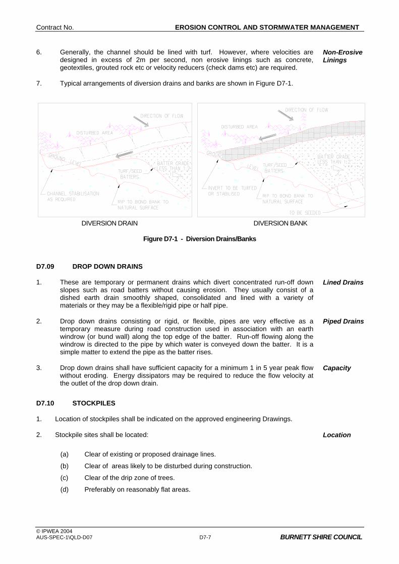
Contract No. EROSION CONTROL AND STORMWATER MANAGEMENT
© IPWEA 2004 AUS-SPEC-1\QLD-D07 D7-7 BURNETT SHIRE COUNCIL
6. Generally, the channel should be lined with turf. However, where velocities are designed in excess of 2m per second, non erosive linings such as concrete, geotextiles, grouted rock etc or velocity reducers (check dams etc) are required.
Non-Erosive Linings
7. Typical arrangements of diversion drains and banks are shown in Figure D7-1.
DIVERSION DRAIN DIVERSION BANK
Figure D7-1 - Diversion Drains/Banks
D7.09 DROP DOWN DRAINS
1. These are temporary or permanent drains which divert concentrated run-off down slopes such as road batters without causing erosion. They usually consist of a dished earth drain smoothly shaped, consolidated and lined with a variety of materials or they may be a flexible/rigid pipe or half pipe.
Lined Drains
2. Drop down drains consisting or rigid, or flexible, pipes are very effective as a temporary measure during road construction used in association with an earth windrow (or bund wall) along the top edge of the batter. Run-off flowing along the windrow is directed to the pipe by which water is conveyed down the batter. It is a simple matter to extend the pipe as the batter rises.
Piped Drains
3. Drop down drains shall have sufficient capacity for a minimum 1 in 5 year peak flow without eroding. Energy dissipators may be required to reduce the flow velocity at the outlet of the drop down drain.
Capacity
D7.10 STOCKPILES
1. Location of stockpiles shall be indicated on the approved engineering Drawings.
2. Stockpile sites shall be located:
(a) Clear of existing or proposed drainage lines.
(b) Clear of areas likely to be disturbed during construction.
(c) Clear of the drip zone of trees.
(d) Preferably on reasonably flat areas.
Location

CONTROL OF EROSION AND SEDIMENTATION Contract No.
© IPWEA 2004 D7-8 AUS-SPEC-1\QLD-D07 BURNETT SHIRE COUNCIL
3. Stockpiles must be protected from erosion and sediment loss by:
(a) The installation of diversion works.
(b) The use of silt fences, haybales etc or other approved controls on the downstream side.
(c) Compaction.
(d) Revegetation if left exposed for longer than 30 days (refer to the Construction Specification for LANDSCAPING for seed mix).
Erosion Protection
4. Site topsoil shall be isolated from subsoil material in separate stockpiles. Separate Stockpiles
D7.11 SEDIMENT BASINS/TRAPS/DAMS
1. Sediment traps are either permanent or temporary sediment control devices that intercept sediment and run-off usually at the final discharge point of the site.
Sediment Control
2. They are formed by excavation and/or by constructing embankments. Construction
3. There are two types, wet and dry basins. Types
4. Preferably sediment traps shall not be located directly upstream of residential areas. Location
5. Basin design must meet the following: Design Criteria
(a) Volume/capacity of the trap shall be 250m3/ha of disturbed site including the building areas.
(b) An allowance of 50m3/ha is required if diversion controls are not used to direct clean upstream water from outside the site away from construction areas.
(c) The capacity shall be measured below the invert of the lowest incoming flow. Otherwise pipelines and associated works will be affected.
(d) A secondary or emergency stabilised spillway must be provided to prevent overtopping of the structure. This shall be directed to a safe overland flow path.
(e) The basin shall have a minimum of 0.5 metres freeboard above the level of the spillway.
(f) The basin shall be surrounded by a manproof fence with lockable gates.
(g) An all weather access must be provided to the basin for maintenance.
(h) The basin shall have an arbitrary length to width ratio of between 2 and 3:1. This encourages soil particle settlement. The entry and exit points should be located at the opposite ends of the basin.
(i) If this is not possible some form of approved baffles shall be installed to minimise short circuiting of the flow.
(j) Discharge of the basin shall be via a perforated riser encapsulated by a filter device for a dry basin. Wet basins shall be flocculated by dosing with gypsum and pumped.
(k) Internal basin batters shall be a maximum of 3:1 and external batters a maximum of 2:1.
Contract No. EROSION CONTROL AND STORMWATER MANAGEMENT
© IPWEA 2004 AUS-SPEC-1\QLD-D07 D7-9 BURNETT SHIRE COUNCIL
(l) All disturbed areas including batters shall be topsoiled and seeded.
(m) In areas known to be affected by high groundwater tables and/or salinity of groundwater, basins shall be designed to be water retentive so that surface drainage water does not leak to the subsurface, recharging groundwater.
6. Permanent wet basin designs slightly vary from the above. Refer to the Stormwater Management Section of this Specification.
Permanent Wet Basins
D7.12 SEDIMENT TRAPS/ BARRIERS FOR MINOR CATCHMENTS
1. These are silt retention/filtering structures of a temporary nature used in situations where the catchment does not exceed 0.5ha.
Filtering Structures
2. Such sediment traps/barriers generally consist of:
(a) silt fences
(b) hay bales
(c) “blue metal” groynes/sausages
(d) filter fabric located beneath stormwater grates
(e) gabions
(f) or a combination of the above.
Barrier Types
3. The choice of material and type of treatment will depend on the size of the catchment the location and the structure being treated such as:
(a) surface inlet pits
(b) kerb inlet pits
(c) catch drain disposal areas
(d) culvert inlets and outlets
(e) minor construction/earthwork sites
(f) check dams/velocity reducers etc.
Location of Structure
D7.13 LEVEL SPREADERS
1. Level spreaders are outlets or "sills" having a level cross section. They convert erosive channelised flows into non-erosive sheet flow.
Convert Flows
2. Level spreaders can only be used to dissipate flows from small catchments. The area below the outlet should be stable and of even cross section so that the water will not re-concentrate into channels.
Location
3. To reduce flow velocity before the spreader, the channel grade shall not exceed 1 per cent for a minimum of 8 metres. The outlet or "sill" width depends on contributing catchment, slope and ground conditions. The minimum width should be four metres, and the maximum width 25 metres. Final discharge should be over a level surface, which may require stabilising by turfing or seeding and fertilising or perhaps lining with a geotextile fabric or something similar.
Design Criteria

CONTROL OF EROSION AND SEDIMENTATION Contract No.
© IPWEA 2004 D7-10 AUS-SPEC-1\QLD-D07 BURNETT SHIRE COUNCIL
D7.14 THE LOCATION OF SHAKEDOWN AREAS AND ACCESS STABILISATION
1. Access to construction sites shall be limited to a maximum of two locations. Number of Accesses
2. Such access locations shall require Council approval. Location Approval
3. Shakedown areas or access stabilisation shall comprise a bed of aggregate on filter cloth or a metal bar cattle grid located at any point where traffic enters or leaves a construction site. Stabilised accesses reduce or eliminate tracking of sediments onto public rights of way or streets. Should such tracking occur the contaminants must be swept off the road way each day or before rain. Clean off draw bars etc after dumping and before starting journey.
Types
4. If a shaker grid is used, this should be so placed as to ensure the vehicles when crossing the grid have sufficient speed to "shake the mud" or other contaminants such as gravel from the vehicle. It must not be placed where the vehicle is slowing to enter a roadway. Cattle grids shall be a minimum length of 7 metres.
Cattle Grid
5. A stabilised access comprises a vehicular pathway suitably constructed to facilitate the collection of any site debris in order to prevent such material leaving the site. Stabilised accesses are generally used on small sites. The entrance shall be at least 15 metres long with a minimum width of 3 metres for a one way entrance and 6 metres for a two way entrance.
Stabilised Access
6. Surface water flowing to the street entrance/exit must be piped under the access, or a berm constructed to direct surface flow away from the exit.
Flow Control
D7.15 WIND EROSION/DUST CONTROL
1. Research has demonstrated average dust emission rates of over 2½ tonnes per hectare per month at urban construction sites. This erosion rate is unacceptable.
Erosion Rate
2. Various measures are available to minimise such emissions, including:- (a) limiting the area of lands exposed to erosive forces through phasing
works/progressive revegetation and/or provision of a protective ground cover and/or keeping the ground surface damp (not wet); and/or
(b) on building sites, installing a barrier fence on the windward side - effective to a distance of 15 times its height, assuming an acceptable soil flux of 5 grams per metre per second. See Figure D7-2.
Treatments
Figure D7-2 - Pollution Control

Contract No. EROSION CONTROL AND STORMWATER MANAGEMENT
© IPWEA 2004 AUS-SPEC-1\QLD-D07 D7-11 BURNETT SHIRE COUNCIL
D7.16 REQUIREMENTS FOR BUILDING SITES
1. The clearing of vegetation and preparation of building pads is to be undertaken in the last stages of the development when the majority of the site has been effectively revegetated.
Site Clearing
2. When the development calls for the construction of a number of buildings, the sediment trap/s and other appropriate sediment controls shall remain operational.
Development Control
3. Cross/catch drains shall be installed on long or steep unpaved driveways, disposing run-off to stable areas.
Driveway Control
4. Where a majority of the lot is disturbed the following controls or measures shall be undertaken:
(a) Silt fences, located around the downstream sides of the lot.
(b) Sediment traps/barriers to be provided to all on-site and adjacent stormwater inlets.
(c) Only one site access to be provided. This may require treatment to prevent soil being tracked from the site.
(d) All subsurface drainage for roofing must be in place prior to the installation of the roof and gutter so downpipes can be immediately connected.
Lot Control
D7.17 EXTERNAL SITE REQUIREMENTS
1. Sediment control devices or stabilising works shall be provided outside construction sites where necessary or as directed by the Superintendent.
Necessary Controls
2. Where increased stormwater run-off is likely to accelerate erosion of any downstream watercourse, the necessary remedial work shall be provided concurrently with other sediment and erosion requirements.
Accelerate Erosion
3. Where sediment is likely to be transported from the site, all immediate downstream drainage inlets shall have appropriate controls installed.
Downstream Controls
4. If such works require entry onto private property, written permission shall be obtained prior to the entry and commencement of such works.
Written Permission
5. All disturbed areas on private property to be reinstated to original condition and to the satisfaction of the owner.
Reinstated
STORMWATER MANAGEMENT
D7.18 GENERAL
1. Most developments mean a change in land use and is usually accompanied by a decline in stormwater quality. This applies to the long term as well as during the short term construction phase. The main components required to enhance stormwater quality are as follows:-
Main Components
(a) Buffer Zones and Filter Strips, being grassed, or similarly treated areas to facilitate the natural assimilation of water pollutants and reduce run-off.
CONTROL OF EROSION AND SEDIMENTATION Contract No.
© IPWEA 2004 D7-12 AUS-SPEC-1\QLD-D07 BURNETT SHIRE COUNCIL
(b) Gross Pollutant Traps (GPT) designed to intercept litter and debris to maintain visual quality in downstream waterways, and to reduce the coarse sediment load on downstream water management structures.
(c) Wet Retention Ponds are permanent sediment ponds designed to allow particulate matter to settle out. They operate under both sedimentation and macrophyte regimes. Note that a large proportion of nutrients adhere to the sediments, and therefore settle out. Other nutrients are removed by macrophytic vegetation as part of the food chain.
(d) Wetland (Nutrient) Filter to enhance the removal of fine sediment and nutrients from stormwater run-off, and are largely dependent on biochemical removal mechanisms (ie, nutrients taken up as part of the plant food chain).
2. Excess nutrients (N,P) lead to eutrophication of waterways. This can cause uncontrolled growth of algae, water weeds etc, which can deplete oxygen levels, kill resident flora and fauna, and reduce recreational appeal. However waterways do have a natural capacity to assimilate nutrients in small to moderate amounts as initial flows have.
Excess Nutrients
3. It is essential to treat the "first flush" of stormwater as these initial flows from urban areas have relatively high pollutant loads. Such heavy pollution results from significant areas of impervious surfaces which do not assimilate pollutants such as dust, fertilisers, pesticides, detergents, etc to the same extent as occurs in more rural environments.
First Flush
D7.19 WET RETENTION BASINS/PONDS
1. Basins designed for water quality control should maximise the extent of settling. In general quiescent conditions and infiltration should be maximised.
Maximise Infiltration
2. A wet retention basin can be located either on-line or off-line as shown in Figure D7-3. Its capacity however needs to be considerably greater if it is located on-line. The wet retention basin usually has some form of energy dissipation at the inlet or a sufficient length-to-width ratio (greater than 2:1) to prevent short circuiting of flow across the pond, although its shape may vary considerably. It should be located such that the basin does not locally raise the subsurface water table under circumstances that might lead to a salinity problem. The pond may vary in size, but it usually has a minimum surface area of about 1 per cent of the total catchment area. At a depth of 2.5 metres, this provides a storage volume approximately equal to the maximum total run-off from a 1 in 1 year storm. Basins may be installed as smaller multiple units (in series) or as large single units.
Location and Size
3. Other design guides that will make the basin efficient in removing particles and provide for public safety, include the following.
Basin Efficiency
(a) The minimum depth should be not less than 1.5 metres with an average depth of 2.5 metres. This discourages macrophyte growth in the deeper portions of the pond and also the breeding of mosquitos.
(b) The basins should have side slopes of approximately 1 in 8. This provides for safety and encourages microphyte growth around edges facilitating nutrient uptake.
(c) The maximum velocity through the pond based on a 1 in 1 year storm should not exceed 0.3 metres per second (at 2.5 metres depth, this is the maximum practical flow velocity at which optimum sediment removal can be achieved).

Contract No. EROSION CONTROL AND STORMWATER MANAGEMENT
© IPWEA 2004 AUS-SPEC-1\QLD-D07 D7-13 BURNETT SHIRE COUNCIL
(d) A minimum freeboard of 0.3 metres should be provided between a restricted discharge outlet for the pond and a storm overflow weir. This discharge outlet should be designed so that the weir overtops on average three times per year.
(e) Inlet and outlet structures should be located at extreme ends of the basin, with short circuiting of flow further minimised by the use of baffles.
4. Basins should be constructed prior to the commencement of any site clearing or construction works, and should be de-silted when the level of sediment reduces the average water depth to less than 1.5 metres.
Construction and Maintenance
5. (a) It may be desirable for the designer of an urban retention basin to incorporate an outlet device that enables dewatering of the basin. This simplifies de-silting, enabling earthmoving equipment to be used for de-silting operations.
(b) An all weather access track shall be provided to the basin for maintenance works.
Outlet Design
Access Track
6. It is generally necessary to incorporate a gross solids trap and trash rack facility on major discharges into the retention basin. This prolongs the life of the basin and prevents the accumulation of litter.
Trash Racks
7. Basins should be surrounded by buffer zones, typically comprising grassed foreshores of not less than 20 metres between the nearest development and the basin. This allows for some infiltration of drainage from developments, permits the drainage authority scope to develop aesthetic surrounds and reduces the likelihood of over the fence dumping of rubbish.
Buffer Zones
8. The settling velocity of particles should service as the basis for design. This, of course, can only be found by conducting standard settling tests or from a knowledge of local soil characteristics. The surface area of the required basin can then be determined from design settling velocities (Randall et al 1982).
Particle Settling
9. Wet retention basins are regarded as impoundments and normal dam safety requirements should be met. A dam must be referred to the Department of Natural Resources if it is:
(a) 10 metres or more in height and has a storage capacity of more than 10 megalitres; or
(b) 5 metres or more in height and has a storage capacity of 50 megalitres or more.
Basin Classifcation
10. If the wet retention basin is within the above categories it must be referred to the Department of Natural Resources.
D7.20 TRASH RACKS
1. Trash racks are usually permanent structures which intercept trash and other debris to protect the aesthetic and environmental quality of water. Where appropriate, construct them upstream of all permanent retarding basins and/or wetlands which have a capacity greater than 5,000 cubic metres, and elsewhere as required by Council.
Environmental Quality
2. Generally, their design criteria should ensure:- Design Criteria
(a) vertical bar screens with bar spacing of 65mm clear;
(b) the length of the rack is consistent with the channel dimension and cause minimal damage when overtopped;

CONTROL OF EROSION AND SEDIMENTATION Contract No.
© IPWEA 2004 D7-14 AUS-SPEC-1\QLD-D07 BURNETT SHIRE COUNCIL
(c) they are as large as practicable while considering all other design criteria - a maximum height of 1.2 metres is suggested;
(d) a structure which remains stable in at least the 20 year ARI event, and is unlikely to cause flooding on adjacent lands as a result of the rack becoming completely blocked in the 100 year ARI event (analysis should include investigation of backwater effects and any consequent flooding);
(e) the structure drains by gravity to a dry condition; and
(f) adequate access for maintenance and which permits the use of mechanical equipment.
3. Where associated with outlet structures for small sediment basins or constructed wetlands, they can be relatively simple in design.
Associated Structures
4. Trash racks may be incorporated in the design of gross pollutant traps. Gross Pollutant Trap
5. Trash racks shall be checked periodically and all debris and silt removed. Maintenance
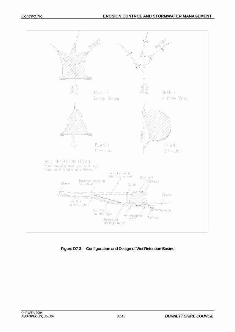
Contract No. EROSION CONTROL AND STORMWATER MANAGEMENT
© IPWEA 2004 AUS-SPEC-1\QLD-D07 D7-15 BURNETT SHIRE COUNCIL
Figure D7-3 - Configuration and Design of Wet Retention Basins

CONTROL OF EROSION AND SEDIMENTATION Contract No.
© IPWEA 2004 D7-16 AUS-SPEC-1\QLD-D07 BURNETT SHIRE COUNCIL
D7.21 GROSS POLLUTANT TRAPS
1. Gross pollutant traps (GPTs) are permanent structures used to trap coarse sediments, trash, litter, and other floating materials. Usually, they are located upstream of constructed wetlands and receiving waters. They consist of an energy dissipater at the upper end, concrete sediment trap and trash rack at the lower end. Sometimes a "mini" wetland is incorporated at the downstream end.
Description
2. These traps have restricted application and each should be justified on individual merits. They have high construction costs and are generally unable to trap silt and clay sized particles other than in relatively small storm events (eg, one year ARI, critical duration storm event). Nevertheless, in some specialised situations their use might be justified, especially where a significant proportion of the bed load consists of particles coarser than 0.04mm (sandy soils) and/or where their construction/maintenance cost can be justified when compared with more conventional sediment retention basins.
Applications
3. GPTs can be defined as major or minor:
(a) major gross pollutant traps can be located on major floodways and waterways to intercept medium to high flows; and
(b) minor, enclosed gross pollutant traps can be located at heads of major floodways and/or where stormwater discharges into floodways or water bodies.
Definition
4. Design traps to intercept at least 75 per cent of sediment with a grain size of 0.04mm or greater under average annual runoff conditions. Further, ensure peak flow velocities are less than 0.3 metres per second in the 1 year ARI storm event, and taking into account any likely backwater effect from a blocked trash rack.
Sediment Interception
5. The structure should have sufficient capacity and stability to discharge the inlet flow with the trash rack fully blocked without flooding adjacent properties.
Capacity
6. Ensure GPTs are capable of gravity drainage to a dry condition for periodic cleaning and maintenance if at all possible.
Maintenance Requirement
D7.22 WETLANDS
1. Wetlands used for improvement of urban run-off quality can be either natural or artificial. They necessarily have to be shallow. Growth of emergent aquatic plants (reeds, etc) should be encouraged by using sideslopes of very low gradient (1 in 8 or less). A large percentage (greater than 25 per cent) of any permanent water should be less than 1 metre deep. The remainder of any open water should have a depth of not greater than 2 metres which will allow submerged plant growth. Figure D7.4 shows a typical wetland arrangement.
Depth and Batters
2. Where wetlands are natural, the Department of Environment and Heritage should be consulted. Reference should also be made to the Brisbane City Council Integrated Environmental Management System Manual.
Natural Wetlands
3. Wetlands, like retention basins, operate more effectively when higher contact time between the pollutants and the biota of the wetland is provided. Thus, like retention basins, wetlands will be more efficient when used in conjunction with upstream flow retardation basins that will maintain run-off closer to pre-development levels. Care shall be taken to avoid situations that recharge the groundwater and elevate the water table so as to develop local salinity problems.
Efficiency
4. A structure should be included to allow manipulation of water levels in the wetland. This will enable control of microphyte, insect populations and facilitate dredging.
Water Levels
Contract No. EROSION CONTROL AND STORMWATER MANAGEMENT
© IPWEA 2004 AUS-SPEC-1\QLD-D07 D7-17 BURNETT SHIRE COUNCIL
5. Where possible, small islands or shoals should be constructed in the upstream areas of the wetland to reduce water velocities, prevent short circuiting and promote aquatic plant growth.
Short Circuiting
6. The performance and life of wetlands, like wet retention basins, will suffer if they are not protected from trash and large particles. It is therefore recommended that trash racks/gross sediment/pollution traps be installed upstream of the wetland.
Wetland Protection
7. Wetlands need to be surrounded by a buffer at least 20 metres wide in order to:-
(a) Restrict access to maintenance vehicles by the installation of an all weather track with a lockable device.
(b) Acts as an infiltration area for surface run-off.
(c) Provide flood protection and secondary assimilation of pollutants.
Buffer Zones
8. These areas are best planted with vegetation native to the area, but they can be used as grassed areas and an aesthetic feature.
Native Vegetation
9. Work in the ACT indicates rates of removal of phosphorous and particles in wetlands are higher than for wet retention basins.
Results
10. In designing wetlands, it is recommended that, as an interim guide, the surface area of the wetlands be a minimum of 0.5 per cent of the catchment which it serves. If wetlands are used in conjunction with wet retention basins, this percentage can be proportionately lowered by allowing for the surface area of the installed wet retention basin.
Surface Area
11. In open water zones, rooted emergent macrophytes appear to be more efficient than substrate microphytes (plants that are attached to the bottom of the water but which do not emerge). This is because the emergent aquatic plants act as an oxygen pump, taking oxygen from the atmosphere into their roots and eventually into the water and so making it available for bacteria and attached algae which grow on the roots on the emergent plants. In the crushed rock zones, emergent aquatic plants are the only types of macrophytes that will grow. These plants will also act as oxygen pumps, and facilitate biological uptake of nutrients and the breakdown of organic matter by bacteria which grow on their roots.
Microphyte Types
12. A variety of plant species should be planted in artificial wetlands to achieve efficient colonisation and maximise pollutant removal. Establishment of plants should be through transplantation of seedlings during spring and early summer.
Revegetation
13. Wetlands will serve other purposes than just improving a quality of urban run-off. They will serve to attract a large range of biota and bird habitat. In areas where they have been installed, they have become an aesthetic feature. Indeed, this may present problems as surrounding communities may resist efforts by the controlling authority to de-silt the wetland.
Aesthetic Feature
14. To minimise mosquito problems, limit expanses of water with more than 50 per cent shading and ensure no sections of water become isolated from the main body.
Insect Problems
15. Islands are highly beneficial as wildlife refuges, especially for birds. Their design should consider the effects on changes in water tables.
Wildlife Refuge
16. Stock ponds with selected native fish to improve the water quality (not for sport), especially species which will control mosquito larvae and select zooplankton in preference to phytoplankton. Avoid use of fish which are bottom feeders.
Native Fish
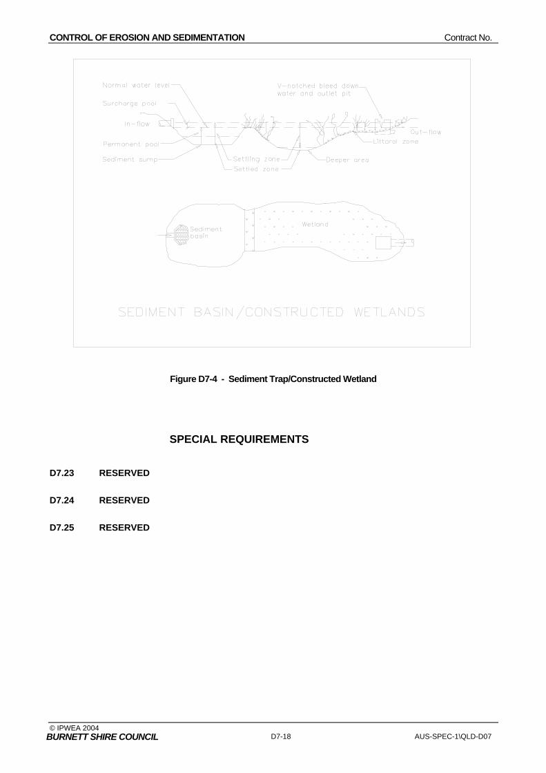
CONTROL OF EROSION AND SEDIMENTATION Contract No.
© IPWEA 2004 D7-18 AUS-SPEC-1\QLD-D07 BURNETT SHIRE COUNCIL
Figure D7-4 - Sediment Trap/Constructed Wetland
SPECIAL REQUIREMENTS
D7.23 RESERVED
D7.24 RESERVED
D7.25 RESERVED

Contract No. WATERFRONT DEVELOPMENT
© IPWEA 2004 AUS-SPEC-1\QLD-D8 BURNETT SHIRE COUNCIL
QUEENSLAND
DEVELOPMENT DESIGN SPECIFICATION
D8
WATERFRONT
DEVELOPMENT


Amendment Record for this Specification Part
This Specification is Council’s edition of the AUS-SPEC generic specification part and includes Council’s primary amendments.
Details are provided below outlining the clauses amended from the Council edition of this AUS-SPEC Specification Part. The clause numbering and context of each clause are preserved. New clauses are added towards the rear of the specification part as special requirements clauses. Project specific additional script is shown in the specification as italic font.
The amendment code indicated below is ‘A’ for additional script ‘M’ for modification to script and ‘O’ for omission of script. An additional code ‘P’ is included when the amendment is project specific.
Amendment Sequence No.
Key Topic addressed in amendment
Clause No.
Amendment Code
Author Initials
Amendment Date
EXAMPLE 1
Provision for acceptance of non conformance with deduction in Payment
XYZ.00 AP KP 2/6/97
1 Adopted by Burnett Shire Council
M RT 10/05/2006

Contract No. WATERFRONT DEVELOPMENT
© IPWEA 2004 AUS-SPEC-1\QLD-D8 BURNETT SHIRE COUNCIL
DESIGN SPECIFICATION D8 WATERFRONT DEVELOPMENT
CLAUSE CONTENTS PAGE
DEVELOPMENT DESIGN SPECIFICATION D8 WATERFRONT DEVELOPMENT
GENERAL ...........................................................................................................................1
D8.01 SCOPE............................................................................................................................................1
D8.02 OBJECTIVE ....................................................................................................................................1
D8.03 REFERENCE AND SOURCE DOCUMENTS ................................................................................1
D8.04 CONSULTATION............................................................................................................................1
D8.05 GENERAL REQUIREMENTS.........................................................................................................2
D8.06 LAND RECLAMATION ...................................................................................................................2
CANALS..............................................................................................................................2
D8.07 PLANNING CONCEPTS.................................................................................................................2
D8.08 PLAN GEOMETRY .........................................................................................................................5
D8.09 WATERWAY DEPTHS ...................................................................................................................5
D8.10 WATERWAY (CANAL) WIDTHS ....................................................................................................5
D8.11 WATERWAY LENGTH ...................................................................................................................6
D8.12 WATERWAY CROSS SECTIONS..................................................................................................6
D8.13 UNDERWATER BATTERS AT CANALS AND SHORELINES ......................................................8
D8.14 ENTRANCES..................................................................................................................................8
HYDRAULICS .....................................................................................................................9
D8.15 STORMWATER MANAGEMENT ...................................................................................................9
D8.16 FLOOD CONTROL STRUCTURES .............................................................................................10
D8.17 TIDAL INFLUENCES ....................................................................................................................10
D8.18 WATER QUALITY INFLUENCES.................................................................................................12
D8.19 EROSION AND SEDIMENTATION INFLUENCES ......................................................................12
STRUCTURES ..................................................................................................................13

GENERAL Contract No. XYZ
AUSPEC-1\C101 - July 97 (Copyright SWR-TM) COUNCIL
D8.20 REVETMENT WALLS...................................................................................................................13
D8.21 JETTIES, PONTOONS AND BOAT RAMPS................................................................................14
D8.22 BRIDGES AND STRUCTURES....................................................................................................16
SPECIAL REQUIREMENTS .............................................................................................17
D8.23 RESERVED ..................................................................................................................................17
D8.24 RESERVED ..................................................................................................................................17
D8.25 RESERVED ..................................................................................................................................17

Contract No. WATERFRONT DEVELOPMENT
© IPWEA 2004 AUS-SPEC-1\QLD-D8 D8-1 BURNETT SHIRE COUNCIL
DEVELOPMENT DESIGN SPECIFICATION D8 WATERFRONT DEVELOPMENT GENERAL
D8.01 SCOPE
1. The work to be executed under this Specification consists of the design of waterway facilities and structures for canal type subdivisions to meet the requirements of Council and the relevant Government Departments.
2. This Specification provides specific requirements related to developments that include water frontages to natural waterways or include the development of artificial waterways. The requirements set out for design in this Specification are to be considered supplementary to the requirements of Council's other design specifications.
D8.02 OBJECTIVE
1. This Specification aims to provide both guidelines and requirements for Designers of developments that include water frontage. The requirements and guidelines seek to ensure waterfront development that is environmentally sound and avoids major commitments to future maintenance and restoration.
D8.03 REFERENCE AND SOURCE DOCUMENTS
(a) Council Specifications D1 - Geometric Road Design D3 - Structures and Bridge Design
(b) Australian Standards AS 2870.1 - Residential slabs and footings - Construction AS 3798 - Guidelines on earthworks for commercial and residential
developments.
(c) QLD State Legislation Harbours Act, 1955 - Section 86, as saved under the Transport Infrastructure
Act. Queensland Environmental Protection Act, 1994, Amendments & Regulations. Water Resources Act, 1989. Canals Act, 1958 and Regulations.
(d) QLD State Authorities Queensland Transport Department of Natural Resources Department of Environment and Heritage - Coastal Management Branch.
D8.04 CONSULTATION
1. Consultation with public authorities is necessarily more comprehensive in the case of waterfront developments. Design proposals shall not be considered by Council until all relevant approvals from public authorities have been obtained. Relevant public authorities include:
Public Authority Approval

GENERAL Contract No. XYZ
© IPWEA 2004 D8-2 AUS-SPEC-1\QLD-D8
BURNETT SHIRE COUNCIL
• The Department of Environment & Heritage - Coastal Management Branch
• Queensland Transport
• Department of Natural Resources
D8.05 GENERAL REQUIREMENTS
1. There are general requirements pertinent to waterfront development which are applied by Council or other public authorities. These requirements include:
Flood Levels
• No adverse effect to flood levels in the area.
• No adverse effect to erosion or deposition conditions within the existing environment.
Erosion
• Revetment walling is to be located with the property boundary. Siltation
D8.06 LAND RECLAMATION
1. A detailed foundation investigation shall be carried out by a registered Professional Engineer Queensland (RPEQ) practising geotechnical engineer to determine the long term bearing capacity of the site. The investigation shall include the bearing capacity of the in-situ and fill components of the foundation. It shall predict the settlement of the finished surface through time (without structural loading). The foundation investigation shall specify any procedures or provisions to ensure that the foundation performance of the site will be suitable for the proposed types of site development in accordance with AS3798.
Fill Bearing Capacity
2. Before any allotments can be sold to the public, a certificate shall be issued by a qualified practising geotechnical engineer, attesting that the site has achieved the desired standard of performance and each site is to be classified in accordance with AS 2870.1.
Geotechnical Certification for Allotments
3. The design of structural foundations should be carried out by a qualified practising structural engineer to ensure compatibility with the inherent foundation properties of the proposed site.
Foundation Design
CANALS
D8.07 PLANNING CONCEPTS
1. Consideration should be given to design of artificial waterways which are more natural in appearance than conventional rectilinear key type canal developments, exhibit superior mixing and tidal exchange performance and which permit straightforward maintenance. See Figure D8.1 for typical layout.
Appearance
2. The location of parks and reserves within the development should be judiciously selected. Location of parks and reserves at the head of canals is desirable.
Positioning Parks
3. Depths shall be kept as shallow as possible, consistent with navigation and other requirements, in order to maximise tidal flushing and mixing by wind action.
Canal Depth
4. The factors involved in selection of water depth for navigation and mooring areas are as follows:
Moorings

Contract No. WATERFRONT DEVELOPMENT
© IPWEA 2004 AUS-SPEC-1\QLD-D8 D8-3 BURNETT SHIRE COUNCIL
• draught of boat
• underkeel clearance (UKC)
• allowance for sedimentation.
5. Water quality within canals must be such that the following are not adversely affected:
• occasional swimming and wading
• boating
• passive recreation
• visual aesthetic acceptability
• freedom from excessive plant and algal growth
• the maintenance of a complete aquatic faunal community.
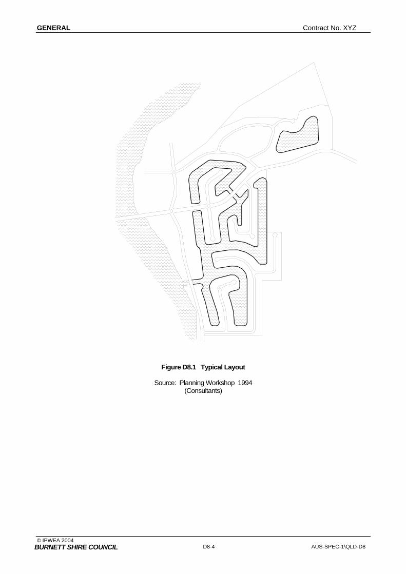
GENERAL Contract No. XYZ
© IPWEA 2004 D8-4 AUS-SPEC-1\QLD-D8
BURNETT SHIRE COUNCIL
Figure D8.1 Typical Layout Source: Planning Workshop 1994 (Consultants)

Contract No. WATERFRONT DEVELOPMENT
© IPWEA 2004 AUS-SPEC-1\QLD-D8 D8-5 BURNETT SHIRE COUNCIL
D8.08 PLAN GEOMETRY
1. Wherever possible, the design of the canal development should incorporate the following factors to promote optimal mixing and exchange:
• provision of bends and meandering canals, and elimination of poorly flushed pockets and coves;
• provision of additional tidal prism at the head of canals by creation of a lake or basin;
• provision of multiple entrances to produce flow-through currents;
• inclusion of artificial islands and roughness elements to enhance local circulation.
Waterway Mixing and Exchange
D8.09 WATERWAY DEPTHS
1. Canal centre depths shall not exceed the depth available in the host waterbody at the canal entrance(s).
Entrance Depth
2. Canal centre depths throughout the canal system shall be uniform or graded towards the canal entrance(s).
3. Depths should be sufficient for safe navigation by craft likely to use the waterway, except in non navigable areas which may be set aside for creation of wetland habitats.
Navigable Depths
4. A maximum canal depth of 2 metres is preferred. Depths in excess of 3 metres below Indian Spring Low Water will not be accepted unless detailed studies are undertaken to satisfy the Department of Environment and Heritage that water quality problems will not arise.
Preferred Maximum Depth
5. Suitable allowance shall be made for sedimentation and bank stability in establishing the design canal depth.
Allowance
D8.10 WATERWAY (CANAL) WIDTHS
1. Two measurements for canal width can be distinguished:
• navigation width: width of canal at the navigation depth
• overall canal width: width of canal between the top of the revetment walls.
These two canal widths are shown in Figure D8-2 for a typical "Dry Beach" canal cross-section.
Width Definition
2. The navigation widths for Main Canals and Side Canals shall be sufficient for safe navigation by two-way and one-way boat traffic respectively, taking into account the size of craft likely to use the waterway. Minimum navigation widths shall be as follows:
Main Canal 5 x Bmax or 20m whichever is the greater
Side Canal 3 x Bmax or 15m whichever is the greater
Where Bmax is the maximum beam of the craft likely to use the waterway.
Where any structures or moored craft encroach into the navigation width, a clear distance of 5 x Bmax and 3 x Bmax shall be provided in Main Canals and Side Canals respectively, measured between structures or craft moored on opposite sides of the canals.
Navigable Widths

GENERAL Contract No. XYZ
© IPWEA 2004 D8-6 AUS-SPEC-1\QLD-D8
BURNETT SHIRE COUNCIL
Figure D8.2 Typical Beach Cross Section
3. The navigation width of the entrance channel shall be sufficient for safe navigation by craft likely to use the waterway taking into account the degree of exposure of the entrance, but shall not be less than 25m.
4. The overall width of any canal shall not be less than 50m. Minimum Overall Width
5. The Department may require that the overall width of canals be increased above the minimum value where it is considered that such widening is necessary to improve mixing and flushing characteristics.
6. Determination of the navigation and overall canal widths shall take into account bank and bed stability considerations.
D8.11 WATERWAY LENGTH
1. Determination of the design canal length(s) shall take into account the following main factors:
• flushing and water quality considerations
• bank and bed stability
• boat travel times.
2. The maximum distance from the host waterbody to the end of the canal(s) shall not exceed 1 kilometre unless studies are undertaken which establish that water quality will be satisfactory.
Maximum Canal Length
D8.12 WATERWAY CROSS SECTIONS
1. The canal cross-section and edge treatment shall be designed in accordance with sound engineering practice by a registered Professional Engineer Queensland (RPEQ) civil engineer, taking into account the type of soil conditions, the likely range of water levels including long term variations, and the applied forces. Engineering studies demonstrating the adequacy of the canal cross-sections and edge treatment shall be made available to the Department of Environment and Heritage.
Engineering Studies
2. The canal cross-section design should conform in principle with the design Alternatives
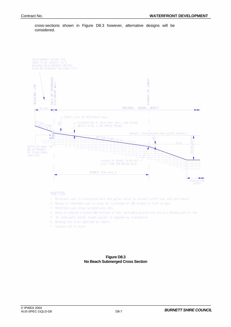
Contract No. WATERFRONT DEVELOPMENT
© IPWEA 2004 AUS-SPEC-1\QLD-D8 D8-7 BURNETT SHIRE COUNCIL
cross-sections shown in Figure D8.3 however, alternative designs will be considered.
Figure D8.3 No Beach Submerged Cross Section

GENERAL Contract No. XYZ
© IPWEA 2004 D8-8 AUS-SPEC-1\QLD-D8
BURNETT SHIRE COUNCIL
D8.13 UNDERWATER BATTERS AT CANALS AND SHORELINES 1. The typical ranges of stable underwater batters for different types of material are
designated in Table D8-1.
Table D8-1 Effect Of Material Type On Underwater Batter
Material Stable Underwater Batter
Stiff Clay 1 : 1.5
Firm Clay 1 : 2 to 1 : 4.5
Sandy Clay 1 : 4 to 1 : 7
Coarse Sand 1 : 3 to 1 : 6
Fine Sand 1 : 5 to 1 : 10
Mud 1 : 8 to 1 : 50
2. Stormwater outlets into beach type canals are to be submerged in the canal waters.
Stormwater Outlets
3. Use of coarse granular materials for beach formation, eg. gravels and cobbles, may cause problems in the form of oyster and barnacle growth.
Beach Material
D8.14 ENTRANCES
1. The proponent is required to adequately demonstrate, by engineering studies, the impact of the physical processes within the host waterbody on the entrance design, and conversely the impact of the entrance design on these processes. These impacts should be considered in the context of establishing:
• entrance location
• number of entrances proposed
• entrance alignment
• entrance dimensions
• the need for flow control structures (eg, weirs or one-way flow devices) if there is more than one entrance.
Engineering Studies
2. For navigable entrances, the width and depth of the entrance shall be sufficient for safe navigation by craft likely to use the waterway.
Navigation
3. The entrance navigation width shall not be less than 25m. Width
4. The entrance depth shall not exceed the depth available in the host waterbody. Depth
5. Determination of entrance dimensions shall take into account bank and bed stability considerations.
Bed Stability
Contract No. WATERFRONT DEVELOPMENT
© IPWEA 2004 AUS-SPEC-1\QLD-D8 D8-9 BURNETT SHIRE COUNCIL
6. The entrance dimensions shall be kept to the minimum practical, consistent with navigation and other requirements, in order to maximise tidal flushing performance and potential for ebb tide scour of any sediments deposited at the entrance.
Tidal Flushing
7. In selecting the entrance location(s) for the canal system, the following factors should be taken into account:
• areas of naturally occurring sedimentation should be avoided;
• areas which would require construction of long access channels, subject to infilling, should be avoided, except where infilling rates can be accurately quantified and be shown to be manageable. Such channels can also act as a sediment "sink" in terms of the sediment budget of the host waterbody and lead to erosion problems;
• the entrance should be sheltered from excessive wave action and strong currents.
Entrance Locations
8. Significant flushing and water quality benefits can be derived from construction of more than one entrance to a canal development. The additional entrance may be navigable or non-navigable.
Second Entrance
9. The alignment of the entrance influences the trajectory of the flood tide currents entering the development, which in turn affects the extent of flood tide penetration and pattern of internal circulations. These factors are important in establishing the degree of flushing under tidal action and hence water quality.
10. Consideration of the alignment of the entrance relative to the host waterbody is also important for several reasons:
• possibility of flow diversion
• safe navigability
• introduction of debris into the canal development.
Alignment
11. The factors involved in selection of water depth for the entrance channel are as follows:
• draft of boat
• underkeel clearance (UKC)
• allowance for sedimentation.
Depth Selection
HYDRAULICS
D8.15 STORMWATER MANAGEMENT
1. The proponent is required to adequately demonstrate that the proposed method of stormwater management will not adversely affect water quality within the canal development and host waterbody, or lead to problems associated with siltation and erosion. Figure D8.4 is a typical solution for stormwater management.
Water Quality
2. The canal allotment shall be graded to ensure as much runoff as possible is directed to the street where it may be collected and then directed into the canals through properly designed stormwater outlets. The preferred system of stormwater discharge is by means of a "drowned outlet" constructed below beach level, incorporating suitable scour protection.
3. Wherever practical, stormwater outlets shall be located at points of maximal flushing, or directly within the host waterbody.
Flushing
4. Stormwater outlets shall not be located at the heads of dead-end canals. Outlets

GENERAL Contract No. XYZ
© IPWEA 2004 D8-10 AUS-SPEC-1\QLD-D8
BURNETT SHIRE COUNCIL
5. Runoff towards the canals from the slope behind the revetment wall shall be intercepted prior to flowing over the revetment wall onto the beach, and otherwise directed into the canal waters without causing beach erosion. The preferred method of collection is by means of a kerb and gutter arrangement incorporated into the revetment wall, with flows then directed via pipework into the canal to discharge below anticipated lowest low water level.
Runoff
6. Suitable allowance for sedimentation near stormwater outlets shall be made in the design of the canal cross-section and/or access made available for future maintenance dredging.
7. Suitable temporary sediment control devices shall be installed during the construction phase to ensure that sedimentation within the canal system is minimised and sedimentation does not occur within the host waterbody.
Sediment Control
D8.16 FLOOD CONTROL STRUCTURES
1. Flood control structures usually include a system of canals and weirs which are to be approved by the Department of Environment and Heritage. Usually detailed designs for flood control structures are commenced only after the overall canals and flood structures have been mathematically and physically modelled and approved by the Department of Environment and Heritage and Council. Preliminary plans are usually prepared as part of a "flood study" which involves modelling procedures.
Modelling
Flood Study
2. Designs must ensure that the proposed works and any raising of the land will not result in any significant increase in flood levels in the area.
D8.17 TIDAL INFLUENCES
1. The level of study of tidal hydraulics necessary to adequately demonstrate the impact of the proposed development on tidal hydraulics, and the effects of the tidal hydraulics on the development, is dependent on a number of factors. It is important that the proponent seek early consultation with the Department of Environment and Heritage.
2. It is likely that detailed studies, involving mathematical and/or physical modelling, will be necessary where it is proposed that the canal subdivision development have more than one entrance, where an understanding of internal tidal circulations is important, or where the development is located within the entrance reach of the host estuary and would involve significant changes to the frictional and shallow water controls on tidal propagation.
Modelling

Contract No. WATERFRONT DEVELOPMENT
© IPWEA 2004 AUS-SPEC-1\QLD-D8 D8-11 BURNETT SHIRE COUNCIL
Figure D8.4 Typical Stormwater Management
Source: Planning Workshop 1994 (Consultants)

GENERAL Contract No. XYZ
© IPWEA 2004 D8-12 AUS-SPEC-1\QLD-D8
BURNETT SHIRE COUNCIL
3. The proponent shall assess variations in the tidal characteristics of the host estuary at the development site taking into account cyclic and long term changes in: estuary shoaling and scour, entrance stability, hydrologic input, mean sea level, and any engineering works (such as large scale estuary dredging, entrance works, or other canal subdivisions) proposed or approved by the various government authorities. The implications of these changes to the design and functionality of the canal subdivision shall be established and accommodated.
Tidal Charac- teristics
4. The proponent shall establish the tidal levels at the proposed development site. These levels may be based on existing information supplied by the Department of Environment and Heritage, where available, or measurements undertaken on behalf of the proponent by a suitably qualified surveyor or civil engineer.
Tidal Levels
5. There is no minimum acceptable tidal range below which canal developments would not be considered. The degree of tidal flushing will however reduce as tidal range decreases, and this effect must be considered in the water exchange and mixing studies required by the Department and outlined elsewhere in the guidelines.
Tidal Range
D8.18 WATER QUALITY INFLUENCES
1. Consideration should be given, where practical, to enhancement of water circulation and/or exchange by the following additional means:
• provision of an additional entrance(s), not necessarily navigable
• provision of additional tidal prism by creation, for example, of a lake or basin at the head of the canal(s)
• provision of bends, curves and island features
• elimination of poorly flushed dead-end canals, pockets and covers
• alignment of the canals in the direction of prevailing winds
• mechanical assistance.
Water Circulation
2. There would appear to be benefit in aligning canals in the direction of prevailing winds if this is possible, providing the canals are not too long, in order to maximise mixing and exchange processes.
Winds
3. Fetch lengths in the direction of strong winds should be minimised to mitigate the potential adverse impacts of wind-generated waves.
Waves
4. The effectiveness of the wind in developing vertical secondary mixing circulation is increased by increasing the width of the water surface in the canals. It follows that broad canals, and lake-type developments, will exhibit enhanced vertical secondary mixing.
Vertical Mixing
D8.19 EROSION AND SEDIMENTATION INFLUENCES
1. Sandy beaches within canal developments require maintenance (nourishment) at regular intervals. Where recovery of the eroded sand from the bad of the canal is unlikely to be feasible, it is necessary to make allowance for ongoing sedimentation on the canal bed from this source.
Sand Beach Maintenance
2. Long canals with sandy shorelines, and aligned with prevailing winds, are likely to experience littoral drift. Generally speaking, the length and alignment of canals should be carefully considered and the potential for littoral drift balanced against the advantages of wind action for promotion of mixing of canal waters.

Contract No. WATERFRONT DEVELOPMENT
© IPWEA 2004 AUS-SPEC-1\QLD-D8 D8-13 BURNETT SHIRE COUNCIL
3. Shoreline structures which extend across the littoral drift zone, eg. some stormwater outlet designs, should be avoided where relatively high littoral drift rates are anticipated, except where special provision has been made to mitigate beach erosion.
Drift
4. In assessing the sediment load carried by stormwater outlets from a given catchment area, it is reasonable to adopt the following sediment quantities per hectare of catchment area per year:
• partially developed urban catchment 5.5 tonnes/ha/yr
• fully developed urban catchment 1.5 tonnes/ha/yr
• rural areas 0.3 tonnes/ha/yr
Sediment Load
5. Stormwater outlets should be arranged so as not to directly or indirectly cause beach erosion or local scour. Consideration should be given to construction of the stormwater outlets below the beach level.
STRUCTURES
D8.20 REVETMENT WALLS
1. There will be some locations in the canal development where it will not be possible to "hold" a sandy beach due to the level and type of wave and current exposure, eg. at so called "external corners". In such locations it will be necessary to adopt an alternative canal edge treatment, most probably a rock revetment.
Wall Requirement
2. Revetment walls are to be designed as retaining walls certified by a practicing registered Structural Engineer (RPEQ) and submitted to Council for approval.
3. Filling is to be composed of material not injurious to the health of the neighbourhood and shall comply with Council's requirements for filling in subdivisions.
Filling Behind Walls
4. The crest of the revetment wall above the design canal profile, for the particular type of canal cross-section adopted, shall conform with the requirements set out in Table D8-2.
Wall Height
5. There is no maximum height for revetment walls as such. However, consistent with the requirements in Table D8-2 the crest level of revetment walls should be kept as low as possible to enable easy access from the allotments onto the waterway, to optimise mixing wind action, and to reduce visual impact.
Maximum Height
6. Determination of the full construction height, structural adequacy and stability of the wall shall take into account an erosion allowance in front of the wall. In the absence of detailed hydraulic tests the allowances for erosion shall not be less than the values specified in Table D8-3.
Erosion Allowance
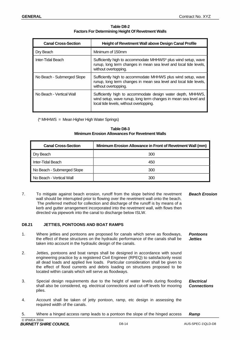
GENERAL Contract No. XYZ
© IPWEA 2004 D8-14 AUS-SPEC-1\QLD-D8
BURNETT SHIRE COUNCIL
Table D8-2 Factors For Determining Height Of Revetment Walls
Canal Cross-Section Height of Revetment Wall above Design Canal Profile
Dry Beach Minimum of 150mm
Inter-Tidal Beach Sufficiently high to accommodate MHHWS* plus wind setup, wave runup, long term changes in mean sea level and local tide levels, without overtopping.
No Beach - Submerged Slope Sufficiently high to accommodate MHHWS plus wind setup, wave runup, long term changes in mean sea level and local tide levels, without overtopping.
No Beach - Vertical Wall Sufficiently high to accommodate design water depth, MHHWS, wind setup, wave runup, long term changes in mean sea level and local tide levels, without overtopping.
(* MHHWS = Mean Higher High Water Springs)
Table D8-3 Minimum Erosion Allowances For Revetment Walls
Canal Cross-Section Minimum Erosion Allowance in Front of Revetment Wall (mm)
Dry Beach 300
Inter-Tidal Beach 450
No Beach - Submerged Slope 300
No Beach - Vertical Wall 300
7. To mitigate against beach erosion, runoff from the slope behind the revetment wall should be interrupted prior to flowing over the revetment wall onto the beach. The preferred method for collection and discharge of the runoff is by means of a kerb and gutter arrangement incorporated into the revetment wall, with flows then directed via pipework into the canal to discharge below ISLW.
Beach Erosion
D8.21 JETTIES, PONTOONS AND BOAT RAMPS
1. Where jetties and pontoons are proposed for canals which serve as floodways, the effect of these structures on the hydraulic performance of the canals shall be taken into account in the hydraulic design of the canals.
Pontoons Jetties
2. Jetties, pontoons and boat ramps shall be designed in accordance with sound engineering practice by a registered Civil Engineer (RPEQ) to satisfactorily resist all dead loads and applied live loads. Particular consideration shall be given to the effect of flood currents and debris loading on structures proposed to be located within canals which will serve as floodways.
3. Special design requirements due to the height of water levels during flooding shall also be considered, eg. electrical connections and cut-off levels for mooring piles.
Electrical Connections
4. Account shall be taken of jetty pontoon, ramp, etc design in assessing the required width of the canals.
5. Where a hinged access ramp leads to a pontoon the slope of the hinged access Ramp
Contract No. WATERFRONT DEVELOPMENT
© IPWEA 2004 AUS-SPEC-1\QLD-D8 D8-15 BURNETT SHIRE COUNCIL
ramp should not exceed 1 in 6 at the lowest anticipated water level. Where pontoons are to be provided, fixed-jetties can be used to reduce the length of hinged access ramps but should not extend past the revetment wall by a distance greater than 7m. The level of the jetty deck should be not greater than 300mm above the top of the revetment wall, and the deck should not rest on the wall. The overall length from the revetment wall to the outer edge of the mooring structure should not exceed 17m and must not extend into the navigation channel.
Geometry
6. Boat ramps for individual allotments are acceptable only in the Dry Beach and Inter-Tidal Beach cross-sections. They should be constructed of concrete and be not less than 150mm thick on the canal side of the revetment wall and have a width not less than 3m. Isolation joints are to be provided so that the concrete slabs forming the ramp are not supported by the revetment wall and can move independently of the wall.
Boat Ramps
7. The ramp should not extend below the position of the change in grade at ISLW-0.3m (Canal Cross-Section/Edge Treatment; Figure D8.3).
End of Ramp
8. A boat ramp can be constructed with its surface either flush with beach surface or the top of the revetment wall at the point of intersection. There are advantages and disadvantages with each approach which should be evaluated during the determination of a standard design. The following issues should be considered:-
• Boat ramps flush with canal beach:
- ramp will be recessed into the revetment wall and allotment
- structural design of the revetment wall will need to allow for recessing
- allotment surface drainage control could be disrupted.
• Boat ramps flush with top of revetment wall:
- ramp will be proud of beach profile which could lead to beach scour through groyne action and local wave reflections
- ramp will constitute an impediment to access for maintenance vehicles (if required).
Ramp Level
9. Boat ramps should be designed to minimise their visual impact. Boat ramps having their surfaces level with the canal beach surface are less visually prominent and are therefore preferable, in terms of visual impact, to ramps which project above the beach surface.
Visual Impact
10. Adequate provision should be made to ensure that scour does not occur under any part of the ramp, eg. by founding the ramp on stable, non-erodible, material and/or incorporating deeper edge beams.
11. Reference should also be made to the Guidelines contained in Section 86 of the Harbours Act.
12. A standard design could be considered for jetties, pontoons and boat ramps (including the means of shore connection) that are proposed as part of the development or that may be constructed by owners at a later date.
Standard Designs
13. Special consideration should be given to the appearance of the structures in the waterway.
Aesthetics

GENERAL Contract No. XYZ
© IPWEA 2004 D8-16 AUS-SPEC-1\QLD-D8
BURNETT SHIRE COUNCIL
14. Public boat launching facilities and marina facilities are generally regarded as unsuitable to a residential canal development because of the difficulty of ensuring adequate privacy for residents. Such facilities should only be considered where adequate and comprehensive environmental safeguards can be incorporated in the design of the development.
Marinas
15. Public boat launching facilities and marina facilities shall be developed in accordance with the Guidelines in Section 86 of the Harbours Act..
Public Facilities
16. Where it is proposed to construct public boat launching facilities within a canal development, consideration shall be given to siting of the launching facilities so as to minimise any adverse noise impacts on adjacent development due to the particular hours of use of the facilities.
Noise
17. Where it is proposed to construct marina facilities within a canal development, consideration shall be given to siting of the marina and design of the marina so as to maximise tidal exchange between the marina basin and the host waterbody.
Marina Basin
18. Ideally, marina basins should be located separately from residential canals and close to the entrance of the overall development.
19. Rectangular marina basins with a ratio of length to breadth greater than 3 should be avoided since internal tidal circulation cells tend to develop which reduce tidal flushing.
20. Marina basins having poorly flushed pockets and coves should be avoided.
21. Rounding of corners within the marina basin will produce greater uniformity in local exchange through the basin, eliminating areas of poor local exchange.
22. For rectangular basins, a single centrally-located entrance produces better flushing behaviour than a single corner-located asymmetric entrance.
23. At public boat launching ramps, consideration should be given to providing holding beaches and boarding jetties or pontoons to facilitate rigging and efficient boarding of craft.
Holding Beaches at Ramps
D8.22 BRIDGES AND STRUCTURES
1. Bridges and structures shall be designed in accordance with the Specification for Structures and Bridge Design. The design life shall be 100 years and the serviceability design flood shall be 1:20 years. The ultimate limit state, that is the capability of the bridge to withstand a flood without collapse, shall be 1:2000 years.
2. Where canals are narrowed at bridge locations, it is likely that complete rock protection of the banks and bed of the canal will be required. Lowering of the canal bed to reduce velocities may also be required.
Narrowing
3. The vertical clearance of any proposed bridge should be checked with the Waterways Authority.
Clearance
4. Where a canal entrance cuts pedestrian access along a public foreshore (eg. by removing the intertidal area) then a footbridge should be provided to ensure continuance of public access and amenity.

Contract No. WATERFRONT DEVELOPMENT
© IPWEA 2004 AUS-SPEC-1\QLD-D8 D8-17 BURNETT SHIRE COUNCIL
SPECIAL REQUIREMENTS
D8.23 RESERVED
D8.24 RESERVED
D8.25 RESERVED


Contract No. CYCLEWAY AND PATHWAY DESIGN
© IPWEA 2004 AUS-SPEC-1\QLD-D9 BURNETT SHIRE COUNCIL
QUEENSLAND
DEVELOPMENT DESIGN SPECIFICATION
D9
CYCLEWAY AND PATHWAY
DESIGN


Amendment Record for this Specification Part
This Specification is Council’s edition of the AUS-SPEC generic specification part and includes Council’s primary amendments.
Details are provided below outlining the clauses amended from the Council edition of this AUS-SPEC Specification Part. The clause numbering and context of each clause are preserved. New clauses are added towards the rear of the specification part as special requirements clauses. Project specific additional script is shown in the specification as italic font.
The amendment code indicated below is ‘A’ for additional script ‘M’ for modification to script and ‘O’ for omission of script. An additional code ‘P’ is included when the amendment is project specific.
Amendment Sequence No.
Key Topic addressed in amendment
Clause No.
Amendment Code
Author Initials
Amendment Date
EXAMPLE 1
Provision for acceptance of nonconformance with deduction in Payment
XYZ.00 AP KP 2/6/97
1 Adopted by Burnett Shire Council
M RT 10/05/2006


Contract No. CYCLEWAY AND PATHWAY DESIGN
© IPWEA 2004 AUS-SPEC-1\QLD-D9 BURNETT SHIRE COUNCIL
DESIGN SPECIFICATION D9 CYCLEWAY AND PATHWAY DESIGN
CLAUSE CONTENTS PAGE
GENERAL ........................................................................................................................... 1
D9.01 SCOPE............................................................................................................................................1
D9.02 OBJECTIVES..................................................................................................................................1
D9.03 REFERENCE AND SOURCE DOCUMENTS ................................................................................1
D9.04 CONSULTATION............................................................................................................................2
D9.05 PLANNING CONCEPTS.................................................................................................................2
D9.06 CYCLEWAY AND PATHWAY TYPES............................................................................................2
D9.07 PROVISIONS FOR CYCLEWAYS AND PATHWAYS AT STRUCTURES....................................3
D9.08 SIGNAGE AND PAVEMENT MARKING ........................................................................................3
D9.09 END OF JOURNEY FACILITIES....................................................................................................3
D9.10 MINIMUM DESIGN STANDARDS..................................................................................................4
D9.11 DOCUMENTATION ........................................................................................................................4
SPECIAL REQUIREMENTS ............................................................................................... 5
D9.12 RESERVED ....................................................................................................................................5
D9.13 RESERVED ....................................................................................................................................5
D9.14 RESERVED ....................................................................................................................................5


Contract No. CYCLEWAY AND PATHWAY DESIGN
© IPWEA 2004 AUS-SPEC-1\QLD-D9 D9-1 BURNETT SHIRE COUNCIL
DEVELOPMENT DESIGN SPECIFICATION D9 CYCLEWAY AND PATHWAY DESIGN
GENERAL
D9.01 SCOPE
1. This Specification sets out requirements to be used in the design of various types of cycleways and pathways.
2. All relevant design principles contained in the AUSTROADS Guide referenced below must be integrated in the design of cycleways and associated infrastructure. This Specification serves as a companion document to the AUSTROADS Guide extended to incorporate basic requirements for pathways.
AUSTROADS
D9.02 OBJECTIVES
1. This Specification aims to set standards and document requirements related to the provision of cycleways and pathways which encourage pedestrian activities and cycling for transportation and recreational purposes. Cycleways and pathways are to be safe and convenient and shall maintain a satisfactory level of service for all pathway users including users with disabilities and limited mobility.
Safety
Level of Service
D9.03 REFERENCE AND SOURCE DOCUMENTS
(a) Council Specifications D1 - Geometric Road Design
(b) Australian Standards AS 1742 - Manual of uniform traffic control devices. AS 2156.1 - Walking tracks, Classification and signage AS 2156.2 - Walking tracks, Infrastructure design AS 2890.3 - Bicycle parking facilities SAA HB69.14 - Guide to traffic engineering practice – Bicycles AS Collection 005 Access and mobility – People with disabilities
(c) Other The Institute of Municipal Engineering Australia, QLD Division - 1995 - Design Guidelines for Subdivisional Streetworks -
“Queensland Streets”. AUSTROADS - Guide to Traffic Engineering Practice - PART 13
Pedestrians, PART 14 Bicycles. - Planning and Designing for Bicycles - NAASRA (now
AUSTROADS) Technical Report June 1988. Ministry of Transport, Victoria - State Bicycle Committee - Planning and Design of Bicycle Facilities,

CYCLEWAY AND PATHWAY DESIGN Contract No.
© IPWEA 2004 D9-2 AUS-SPEC-1\QLD-D9 BURNETT SHIRE COUNCIL
D9.04 CONSULTATION
1. The Designer must consult with Council, the Developer's Landscape Architects/Designers and relevant authorities prior to and during the preparation of cycleway and pathway design.
Landscape Designers Public Authorities
D9.05 PLANNING CONCEPTS
1. Council will provide specific requirements for cycleways and pathways in Council's Subdivision Code as well as in a regional or local strategic bicycle plan. The Designer will need to enquire about such documents and comply with requirements defined.
Subdivision Code and Bicycle Plan
2. The Designer should be familiar with cycleway geometric design requirements in terms of:
- width
- grade
- stopping sight distance
- change in grade
- horizontal curvature
- crossfall and drainage
- superelevation
- sight distance on horizontal curves
These requirements are discussed in the AUSTROADS Guide.
Geometric Design
AUSTROADS Guide
3. The Designer shall incorporate all the requirements for disabled access as appropriate for pathway design in accordance with any Council Policy or Development Control Plan on Access and Mobility and AS Collection 005.
Disabled Access
D9.06 CYCLEWAY AND PATHWAY TYPES
1. Cycleways can be provided on road and off road. The AUSTROADS Guide provides detailed descriptions, warrants, widths, pavement marking etc for the majority of these cycleways.
On Road Off Road
2. Common alternative cycleway types include: On Road Shared Parking/Bicycle Lanes Wide Kerbside Lanes Shared Traffic Lanes Exclusive Bicycle Lane Sealed Shoulder Off Road Shared Use Bicycle/Pedestrian Pathway Separated Pathway Exclusive Cycleway
The AUSTROADS Guide provides advice on the suitability of pavement conditions, AUSTROADS

Contract No. CYCLEWAY AND PATHWAY DESIGN
© IPWEA 2004 AUS-SPEC-1\QLD-D9 D9-3 BURNETT SHIRE COUNCIL
drainage pit grates etc for on road cycleways. Guide
3. Common pathway types include: Exclusive Pedestrian Pathways Shared Use Bicycle/Pedestrian Pathways
By definition pedestrian pathways are "off road" in that pedestrian facilities routinely designed adjacent to roadways are termed footpaths and are designed to meet criteria outlined in Council's Subdivision Code and typically related to road cross section detailing.
Footpaths
4. Pathways by comparison diverge from the road alignment either within the road reserve or across land reserves. Pathways can be provided in conjunction with overland floodways or retention basins.
Land Reserves
D9.07 PROVISIONS FOR CYCLEWAYS AND PATHWAYS AT STRUCTURES
1. Designers shall consider the best way to provide for the uninterrupted movement of cyclists and pedestrians at proposed and existing structures wherever possible. Structures include bridges and underpasses over rivers, roads or railways. The reference and source documents provide information on:
- acceptable widths and clearances
- types of cycleways and pathways
- handrails
- bicycle bridges
- approach ramps
etc.
Bridges Underpasses
D9.08 SIGNAGE AND PAVEMENT MARKING
1. The Designer shall provide adequate signposting design for cycleways and pathways.
2. Signs and pavement marking will provide for the safe and convenient use of the facility. The signs and pavement marking will comply with AS 1742.9 Bicycle facilities.
Compliance
D9.09 END OF JOURNEY FACILITIES
1. Consideration must be given to the design of adequate facilities at common destinations of cyclists and pedestrians so as to encourage cycleway and pathway usage.
2. Such facilities could include:
- seats
- standby areas
- secure bicycle parking
- picnic facilities
Facilities
3. Bicycle parking installation design should meet appropriate criteria discussed in the AUSTROADS Guide and be fabricated to meet AS 2890.3.
Parking

CYCLEWAY AND PATHWAY DESIGN Contract No.
© IPWEA 2004 D9-4 AUS-SPEC-1\QLD-D9 BURNETT SHIRE COUNCIL
D9.10 MINIMUM DESIGN STANDARDS
1. Notwithstanding the guidelines provided in this Specification and referenced documents the following minimum standards have been determined as shown in Table D9.1 as per “Queensland Streets”.
Table D9.1 Minimum Design Standards
Cycleway Pathway Shared Use Pathway
Path Width 2.0m 1.2m 2.0m
Formation Width 3.0m 2.0m 3.0m
Crossfall min. max.
1:40 1:20
1:40 1:20
1:40 1:20
Grade max. 2% for 450m 5% for 90m 10% for 30m
8.0% 12.5%
Absolute max
2% for 140m 3% for 70m 4% for 40m 5% for 30m
D9.11 DOCUMENTATION
1. The following listing outlines Council's minimum requirements for presentation of cycleway and/or pathway designs.
• All plans for cycleways/pathways are to be presented at the reduction ratio 1:500.
Plans
• The cycleway plan sheet may be incorporated into the road plan where clarity permits. Specific details are to be provided at reduction ratio 1:200.
• Longitudinal Sections will be required for all off-road cycleways where grades exceed 4%.
Long Sections
• Longitudinal Sections will have reduction ratios of 1:500 horizontal and 1:100 vertical.
• Cross Sections will be presented at 1:100 reduction ratio (natural) and transition tables will be required where cross falls vary or superelevation is provided.
Cross Sections
• A typical cross section will be detailed to indicate pavement materials and layer depths.
2. All Drawings shall be in accordance with the minimum drafting requirements in the Specification for QUALITY ASSURANCE REQUIREMENTS FOR DESIGN.

Contract No. CYCLEWAY AND PATHWAY DESIGN
© IPWEA 2004 AUS-SPEC-1\QLD-D9 D9-5 BURNETT SHIRE COUNCIL
SPECIAL REQUIREMENTS
D9.12 RESERVED
D9.13 RESERVED
D9.14 RESERVED
Contract No. BUSHFIRE PROTECTION
© IPWEA 2004 AUS-SPEC-1\QLD-D10 BURNETT SHIRE COUNCIL
QUEENSLAND
DEVELOPMENT DESIGN SPECIFICATION
D10
BUSHFIRE PROTECTION


Contract No. BUSHFIRE PROTECTION
© IPWEA 2004 AUS-SPEC-1\QLD-D10 BURNETT SHIRE COUNCIL
Amendment Record for this Specification Part
This Specification is Council’s edition of the AUS-SPEC generic specification part and includes Council’s primary amendments.
Details are provided below outlining the clauses amended from the Council edition of this AUS-SPEC Specification Part. The clause numbering and context of each clause are preserved. New clauses are added towards the rear of the specification part as special requirements clauses. Project specific additional script is shown in the specification as italic font.
The amendment code indicated below is ‘A’ for additional script ‘M’ for modification to script and ‘O’ for omission of script. An additional code ‘P’ is included when the amendment is project specific.
Amendment Sequence No.
Key Topic addressed in amendment
Clause No.
Amendment Code
Author Initials
Amendment Date
EXAMPLE 1
Provision for acceptance of non-conformance with deduction in Payment
XYZ.00 AP KP 2/6/97
1 Adopted by Burnett Shire Council
M RT 10/05/2006


Contract No. BUSHFIRE PROTECTION
© IPWEA 2004 AUS-SPEC-1\QLD-D10 BURNETT SHIRE COUNCIL
CONTENTS CLAUSE PAGE
GENERAL ...........................................................................................................................1
D10.01 SCOPE............................................................................................................................................1
D10.02 OBJECTIVES..................................................................................................................................1
D10.03 REFERENCE AND SOURCE DOCUMENTS ................................................................................1
DESIGN CRITERIA.............................................................................................................2
D10.04 GENERAL .......................................................................................................................................2
D10.05 FIRE PROTECTION ZONES..........................................................................................................3
D10.06 FUEL REDUCED ZONE .................................................................................................................4
D10.07 FUEL FREE ZONE .........................................................................................................................5
D10.08 MODIFICATIONS TO FUEL REDUCED AND FUEL FREE ZONES .............................................6
D10.09 INTERNAL ACCESS FROM SUBDIVISION ROADS.....................................................................7
D10.10 STAGING WORKS .........................................................................................................................7
SPECIAL REQUIREMENTS ...............................................................................................8
D10.11 RESERVED ....................................................................................................................................8
D10.12 RESERVED ....................................................................................................................................8
D10.13 RESERVED ....................................................................................................................................8

Contract No. BUSHFIRE PROTECTION
© IPWEA 2004 AUS-SPEC-1\QLD-D10 D10-1 BURNETT SHIRE COUNCIL
DEVELOPMENT DESIGN SPECIFICATION D10 BUSHFIRE PROTECTION
GENERAL
D10.01 SCOPE
1. The work to be executed under this Specification consists of the design of bushfire protection facilities to protect life and property and bring a fire to a halt.
2. The Specification contains procedures for the design of fire protection facilities. Designs shall be carried out to satisfy requirements of the Council and guidelines as provided by the Queensland Fire Service - Rural Fire Brigade. Consultation with Council's Fire Control Officer or other authorised officer may be required.
D10.02 OBJECTIVES
1. This Specification aims to outline the requirements that will minimise bushfire hazard in developments. The requirements are particularly pertinent to rural developments but should be an integral part of urbanised development as well. The concepts proposed need to be incorporated at an early stage of development design.
Rural Development Urban Development
D10.03 REFERENCE AND SOURCE DOCUMENTS
(a) Council Specifications C501 - Bushfire Protection (Perimeter Tracks)
(b) QLD State Legislation Queensland Fire & Rescue Act, 1996 Integrated Planning Act (IPA)
(c) QLD State Authorities Queensland Fire Service Rural Fire Brigade Queensland Department of Environment and Heritage
(d) Other Standards Australia (AS3959:1999) Construction of buildings in bushfire-prone
areas Standards Australia, Commonwealth Scientific and Industrial Research
Organisation (CSIRO) Building in Bushfire-prone areas: Information and advice,
SAA HB 36-1993 Australasian Fire Authority Council Guidelines Queensland State Planning Policy 1/03 Queensland Department of Natural Resources and Mines A Guide to Fire Management in Queensland (Incorporating
fire management theory and departmental practice) (2000)

BUSHFIRE PROTECTION Contract No.
© IPWEA 2004 D10-2 AUS-SPEC-1\QLD-D10 BURNETT SHIRE COUNCIL
Queensland Department of Local Government and Planning, and Queensland Fire and Rescue Service Bushfire Prone Areas: Siting and Design of Residential
Buildings (1997) Department of Local Government and Planning Protecting your home against bushfire attack (2000) Department of Bushfire Services (Now NSW Rural Fire Service) - Planning for Bushfire Protection. A Guide for Land Use
Planners, Fire Authorities, Developers and Home Owners. May 1991.
Californian Department of Forestry - "Fire Safety Guides for Residential Development in
California" 1980. Insurance Council of Australia. - "Bushfire Safety in Urban Fringe Areas." Luke, R.H. - "Before the Fires Start."
DESIGN CRITERIA
D10.04 GENERAL
1. Where a subdivision will abut unimproved timber in a bushfire prone area (as classified by Council), perimeter tracks are to be located immediately between the created allotment and the bushland within a minimum cleared width of 6m, and have a minimum formed width of 4m. Such roads shall be adequately drained to provide all weather access for fire fighting vehicles.
Perimeter Tracks
2. The perimeter track is to be contained within a 20m reservation or easement which boarders those allotments abutting the bushfire prone area. Such a reserve is to be contained wholly within the development site and serve as a basis for fire protection measures to be undertaken and will not be considered as part of the public reserve dedication applicable to the development.
20m Reservation
3. Access is to be provided from the above described reservation from the local road system at regular intervals in a system of 'loops'.
Access
4. For those subdivisions receiving reticulated water, fire hydrants shall be situated at appropriate intervals or near where potential fire hazard areas exist as determined by Council.
Fire Hydrants
5. In Bushfire Prone Areas, the water supply must be reliable and have sufficient flow and pressure for fire-fighting purposes at all times. In subdivisions without a pressurized reticulated water supply, each allotment shall have a volume of water available of not less than 5000 litres which may be provided by way of:
a) A separate tank; and / or
b) A swimming pool; and / or
c) A dam.
The outlet pipe is to be 50mm in diameter and fitted with a 50 mm male Camlock
Bushfire Prone Areas

Contract No. BUSHFIRE PROTECTION
© IPWEA 2004 AUS-SPEC-1\QLD-D10 D10-3 BURNETT SHIRE COUNCIL
standard Rural Fire Brigade fitting.
6. In Bushfire Prone Areas water supplies are also to be provided on public land for fire-fighting purposes and are to be readily accessible to Fire Brigades. This could include the provision of concrete water tanks with a male 50 mm Camlock fitting and holding at least 22,500 litres or a dam.
7. Council's Fire Control Officer or other authorised officer shall be consulted for technical advice in relation to bushfire protection of subdivisions.
Consultation
8. Fire protection zones access tracks and perimeter tracks shall be clearly indicated on the subdivision plan. Erosion control features and revegetation requirements shall also be indicated in the subdivision plan.
Notation on Plans
D10.05 FIRE PROTECTION ZONES
1. The provision of Fire Protection Zones (FPZs) shall occur as part of the development of the subdivision pattern. Each individual allotment shall have adequate space for the main building (usually a dwelling), an area of open space (front.back or side yard) and the FPZ (which may include part of the yard area and/or neighbouring properties). Figure D10.1 illustrates a typical FPZ.
Part of Development
Figure D10.1 Fire Protection Zone
2. FPZs shall be required for any development fronting a bush fire hazard area, whether a single dwelling, a group of isolated dwellings or an urban subdivision. They act as a buffer zone between the development and the fuel.
Buffer Zone
3. The primary purpose of FPZs is to ensure that a progressive reduction of fuel occurs between the bush fire hazard and any combustible structures within the development.
Reduction of Fuel
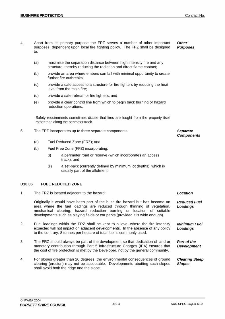
BUSHFIRE PROTECTION Contract No.
© IPWEA 2004 D10-4 AUS-SPEC-1\QLD-D10 BURNETT SHIRE COUNCIL
4. Apart from its primary purpose the FPZ serves a number of other important purposes, dependent upon local fire fighting policy. The FPZ shall be designed to:
Other Purposes
(a) maximise the separation distance between high intensity fire and any structure, thereby reducing the radiation and direct flame contact;
(b) provide an area where embers can fall with minimal opportunity to create further fire outbreaks;
(c) provide a safe access to a structure for fire fighters by reducing the heat level from the main fire;
(d) provide a safe retreat for fire fighters; and
(e) provide a clear control line from which to begin back burning or hazard reduction operations.
Safety requirements sometimes dictate that fires are fought from the property itself
rather than along the perimeter track.
5. The FPZ incorporates up to three separate components:
(a) Fuel Reduced Zone (FRZ); and
(b) Fuel Free Zone (FFZ) incorporating:
(i) a perimeter road or reserve (which incorporates an access track); and
(ii) a set-back (currently defined by minimum lot depths), which is usually part of the allotment.
Separate Components
D10.06 FUEL REDUCED ZONE
1. The FRZ is located adjacent to the hazard:
Originally it would have been part of the bush fire hazard but has become an area where the fuel loadings are reduced through thinning of vegetation, mechanical clearing, hazard reduction burning or location of suitable developments such as playing fields or car parks (provided it is wide enough).
Location
Reduced Fuel Loadings
2. Fuel loadings within the FRZ shall be kept to a level where the fire intensity expected will not impact on adjacent developments. In the absence of any policy to the contrary, 8 tonnes per hectare of total fuel is commonly used.
Minimum Fuel Loadings
3. The FRZ should always be part of the development so that dedication of land or monetary contribution through Part 5 Infrastructure Charges (IPA) ensures that the cost of fire protection is met by the Developer, not by the general community.
Part of the Development
4. For slopes greater than 20 degrees, the environmental consequences of ground clearing (erosion) may not be acceptable. Developments abutting such slopes shall avoid both the ridge and the slope.
Clearing Steep Slopes
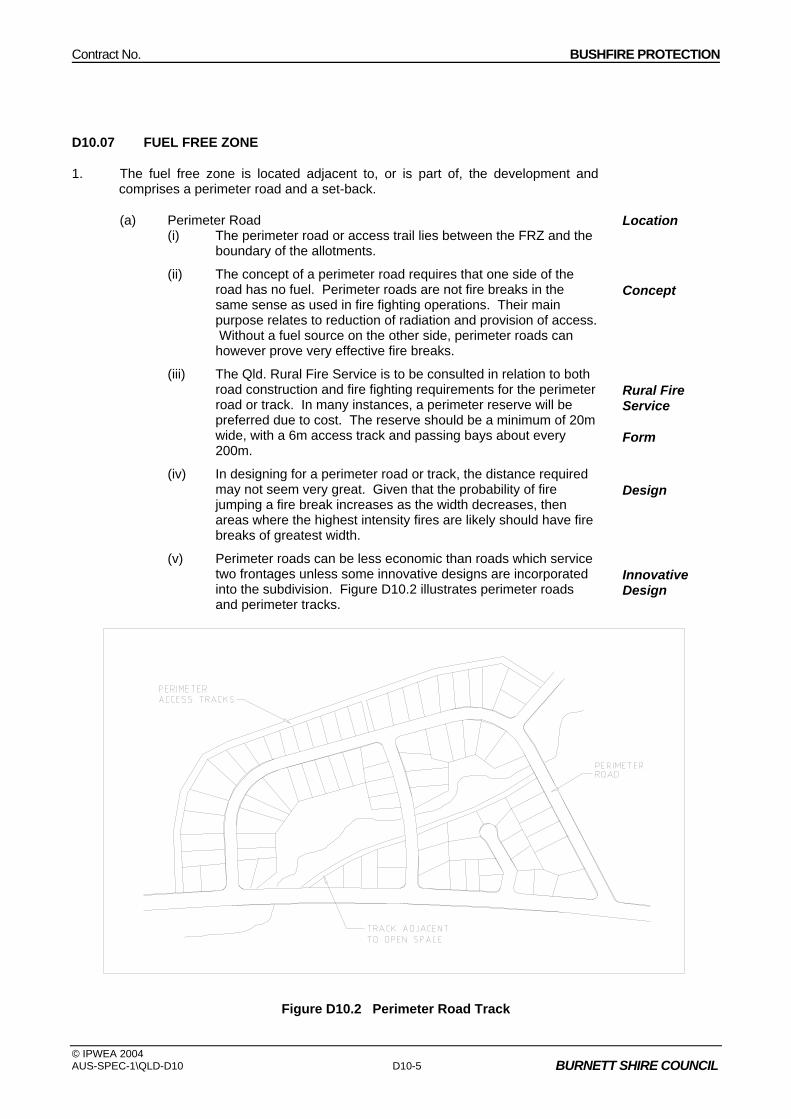
Contract No. BUSHFIRE PROTECTION
© IPWEA 2004 AUS-SPEC-1\QLD-D10 D10-5 BURNETT SHIRE COUNCIL
D10.07 FUEL FREE ZONE
1. The fuel free zone is located adjacent to, or is part of, the development and comprises a perimeter road and a set-back.
(a) Perimeter Road (i) The perimeter road or access trail lies between the FRZ and the
boundary of the allotments.
Location
(ii) The concept of a perimeter road requires that one side of the road has no fuel. Perimeter roads are not fire breaks in the same sense as used in fire fighting operations. Their main purpose relates to reduction of radiation and provision of access. Without a fuel source on the other side, perimeter roads can however prove very effective fire breaks.
Concept
(iii) The Qld. Rural Fire Service is to be consulted in relation to both road construction and fire fighting requirements for the perimeter road or track. In many instances, a perimeter reserve will be preferred due to cost. The reserve should be a minimum of 20m wide, with a 6m access track and passing bays about every 200m.
Rural Fire Service
Form
(iv) In designing for a perimeter road or track, the distance required may not seem very great. Given that the probability of fire jumping a fire break increases as the width decreases, then areas where the highest intensity fires are likely should have fire breaks of greatest width.
Design
(v) Perimeter roads can be less economic than roads which service two frontages unless some innovative designs are incorporated into the subdivision. Figure D10.2 illustrates perimeter roads and perimeter tracks.
Innovative Design
Figure D10.2 Perimeter Road Track

BUSHFIRE PROTECTION Contract No.
© IPWEA 2004 D10-6 AUS-SPEC-1\QLD-D10 BURNETT SHIRE COUNCIL
(vi) Perimeter roads that do not require clearing or maintenance (compared to tracks), can be cheapest in the long term. Ultimately the decision between a road or track depends on the local council's subdivision and bush fire fighting policies.
No Clearance or Maintenance
(vii) Tracks shall be constructed to Council requirements.
(b) Set-back
(i) Part of the allotment can be used as a section of the buffer by setting a minimum lot depth and rear setback. This can ensure that sufficient room (30-35m) is available to allow for erection of a dwelling that does not encroach upon the rear of the allotment.
Minimum Lot Depth
(ii) The policy previously required a minimum of 40m lot depth in order to be consistent with the average minimum lot depth in bushland residential developments. Based on the requirement to maximise the distance between hazard and structures on reasonable grounds (as developed above) and a 30m wide building envelope which includes the surrounding yard, there is no justification for a 40m minimum lot depth in some instances.
Previous Policy
D10.08 MODIFICATIONS TO FUEL REDUCED AND FUEL FREE ZONES
1. Fire authorities would generally be reluctant to agree to modifications in the width of either the FRZ or the FFZ.
2. Modifications to the width of either the FRZ or the FFZ shall only be made with the written approval from Council’s fire control authority and based on an examination of the particular cases rather than according to any formula.
Approval of Fire Control Authority
3. Modifications would need to take account of adjacent or proposed development. Some difficulties arise where new development abuts existing development that is a fire hazard because of the nature of its usage (eg forests, parks etc). The general principle is that fire protection should be shared by both users which may require a certain level of negotiation outside the planning system.
Adjacent Development
4. Even without an extensive area of fuel outside the FRZ, intense fires can develop if the FRZ has not been hazard-reduced and if the fire begins as a line ignition from spotting embers.
5. Under adverse conditions fires moving up a slope may not be slowed by the presence of rocky outcrops and ledges, even though the continuity of the fuel bed may be broken.
Contract No. BUSHFIRE PROTECTION
© IPWEA 2004 AUS-SPEC-1\QLD-D10 D10-7 BURNETT SHIRE COUNCIL
D10.09 INTERNAL ACCESS FROM SUBDIVISION ROADS
1. The provision of adequate internal access is also controlled by subdivision design. Subdivision roads shall, however, incorporate the following features for fire protection purposes:
Incorporated in Subdivision Design
(a) width, vertical clearances and any dips and crests which allow the two way movement of firefighting appliances;
(b) construction standards of roads and any bridges which allow for the carrying of fully loaded fire appliances (28 tonnes or 8 tones per axle);
(c) curves which have a minimum inner radius of 12m and are minimal in number;
(d) maximum grades which do not exceed 15% (1:7) and preferably not more than 10% (1:10);
(e) clearly signposted roads;
(f) Culs-de-sac which do not exceed 200 metres in length;
(g) Culs-de-sac which incorporate a minimum turning circle of 12.5m diameter;
(h) Culs-de-sac are not included in any Bushfire Prone Areas or Extreme Brushfire Hazard Areas; and
(h) a road network which connects regularly to any access tracks.
D10.10 STAGING WORKS
1. When considering the rate of development, planners shall provide for initial development to occur on the hazard perimeter of the development. A line of dwellings will tend to minimise the threat to the entire subdivision by limiting the hazard interface.
Initial Development on Hazard Perimeter
2. Scattered developments on the other hand, will allow a continuous network of fuel to threaten individual buildings until development is substantially underway.
Scattered Developments
3. For similar reasons, new developments should be 'tacked' onto old developments to minimise the hazard perimeter.
Minimise Hazard Perimeter
4. It is important that much of the bush fire protection is incorporated into the design of the development, rather than into individual allotments.
Incorporated in Subdivision Design

BUSHFIRE PROTECTION Contract No.
© IPWEA 2004 D10-8 AUS-SPEC-1\QLD-D10 BURNETT SHIRE COUNCIL
SPECIAL REQUIREMENTS
D10.11 RESERVED
D10.12 RESERVED
D10.13 RESERVED

Contract No. WATER RETICULATION
© IPWEA 2004 AUS-SPEC-1\QLD-D11 BURNETT SHIRE COUNCIL
QUEENSLAND
DEVELOPMENT DESIGN SPECIFICATION
D11
WATER RETICULATION
AUS-SPEC appreciates the role of the Water Directorate incomprehensively updating the design and constructionspecifications for water and sewer works.

Contract No. WATER RETICULATION
© IPWEA 2004 AUS-SPEC-1\QLD-D11 BURNETT SHIRE COUNCIL
INSTRUCTION FOR SPECIFICATION PREPARATION (Delete this box before printing)
LOCAL REQUIREMENTS FOR WATER RETICULATION DESIGN
1. This Specification recognises that each Council may need to vary the Specifications to meet local requirements. The items below may be taken into account in varying this design specification and the construction specification C401.
2. The Water Directorate, a close partner of the Institute of Public Works Engineering Australia (IPWEA) may provide additional information regarding the following:
a) A complete list of Australian Standards relevant to Water Reticulation compiled as a result of a survey of Standards in use.
b) A schedule of training organisations available to provide accreditation to Contractors and Superintendents.
c) A schedule of organisations or Councils available to undertake disinfection of water mains together with guidelines for disinfection.
d) A schedule of products in use compiled as a result of a survey of users.
e) Advice on handling different requirements between the Council and any subsidising Authority. Differences identified include:
i. Provision of more expensive materials, fittings and pumps.
ii. Water supply storage heads (20m is called up compared to a minimum requirement of 12m).
3. The grading requirements called up for sand bedding may need to be checked where Council wishes to facilitate local acquisition. (C401.26.2, Table C401.2).
4. Valve opening direction varies within and between Water Authorities. The requirements of the specifications may need to be checked against existing installations. (D11.06.9).
5. Working pressures vary, especially between the inland and the coast. The requirements of the specifications may need to be checked against existing conditions. (D11.05.1, D11.05.4, D11.09.1).
6. Materials for PVC and PE fittings may be different for different size pipes. The requirements of the specifications may need to be checked against existing installations. (C401.04.1, C401.10.3).
7. The requirement for the location of property services varies between Councils. The requirements of the specifications may need to be checked against existing installations. (D11.06.6).
8. Each Council may wish to consider any special requirements for the installation of long length water service connections. (Expand on D11.06.6).
9. The method of marking access to fittings varies between Councils. The requirements of the specifications may need to be checked against existing requirements. (C401.41.3).
WATER RETICULATION Contract No.
© IPWEA 2004 AUS-SPEC-1\QLD-D11 BURNETT SHIRE COUNCIL
10. The number and timing for receipt of documents called up varies between Councils. The requirements of the specifications may need to be checked against existing requirements.
11. Councils require varying lead times for notices to be given. The requirements of the specifications may need to be checked against existing requirements.
12. Council may wish to consider the option for installation of curved pipes (eg in cul-de-sacs). (D11.10.3).
Contract No. WATER RETICULATION
© IPWEA 2004 AUS-SPEC-1\QLD-D11 BURNETT SHIRE COUNCIL
Amendment Record for this Specification Part
This Specification is Council’s edition of the AUS-SPEC generic specification part and includes Council’s primary amendments.
Details are provided below outlining the clauses amended from the Council edition of this AUS-SPEC Specification Part. The clause numbering and context of each clause are preserved. New clauses are added towards the rear of the specification part as special requirements clauses. Project specific additional script is shown in the specification as italic font.
The amendment code indicated below is ‘A’ for additional script ‘M’ for modification to script and ‘O’ for omission of script. An additional code ‘P’ is included when the amendment is project specific.
Amendment Sequence No.
Key Topic addressed in amendment
Clause No.
Amendment Code
Author Initials
Amendment Date
EXAMPLE 1
Provision for acceptance of non conformance with deduction in Payment
XYZ.00 AP KP 2/6/97
1 Adopted by Burnett Shire Council M RT 10/05/2006


Contract No. WATER RETICULATION
© IPWEA 2004 AUS-SPEC-1\QLD-D11 BURNETT SHIRE COUNCIL
SPECIFICATION D11 - WATER RETICULATION CONTENTS CLAUSE PAGE
GENERAL ........................................................................................................................... 1
D11.01 SCOPE............................................................................................................................................1
D11.02 OBJECTIVE ....................................................................................................................................1
D11.03 REFERENCE AND SOURCE DOCUMENTS ................................................................................1
DESIGN CRITERIA............................................................................................................. 3
D11.04 GENERAL .......................................................................................................................................3
D11.05 RETICULATION PRESSURE.........................................................................................................3
D11.06 PIPELINE ........................................................................................................................................4
D11.07 LOCATION......................................................................................................................................5
D11.08 MINE SUBSIDENCE AREAS AND AREAS OF SLIPPAGE...........................................................5
MATERIALS........................................................................................................................ 5
D11.09 GENERAL (WSAA 03 Part 2) .........................................................................................................5
D11.10 UNPLASTICISED AND MODIFIED PVC (uPVC and PVC-M) PIPE..............................................6
D11.11 ACRYLONITRILE BUTADIENE STYRENE (ABS) PIPE AND FITTINGS......................................7
D11.12 DUCTILE IRON (DI) PIPE AND FITTINGS ....................................................................................7
D11.13 STEEL PIPE AND FITTINGS .........................................................................................................7
D11.14 POLYETHYLENE PIPE AND FITTINGS ........................................................................................8
D11.15 GLASS REINFORCED PLASTIC (GRP) AND FITTINGS..............................................................8
D11.16 COPPER PIPE AND FITTINGS......................................................................................................8
PUMP STATIONS ............................................................................................................... 8
D11.17 GENERAL .......................................................................................................................................8
D11.18 PUMP..............................................................................................................................................9
D11.19 ELECTRICAL ................................................................................................................................10
D11.20 ELECTRICAL POWER SUPPLY..................................................................................................10
D11.21 TELEMETRY.................................................................................................................................10

WATER RETICULATION Contract No.
© IPWEA 2004 AUS-SPEC-1\NSW-D11 BURNETT SHIRE COUNCIL
D11.22 LADDERS .....................................................................................................................................11
D11.23 OTHER APPURTENANCES ........................................................................................................11
DOCUMENTATION........................................................................................................... 11
D11.24 RETICULATION............................................................................................................................11
D11.25 PUMP STATION ...........................................................................................................................12
D11.26 ASSET REGISTER.......................................................................................................................13
SPECIAL REQUIREMENTS ............................................................................................. 13
D11.27 RESERVED ..................................................................................................................................13
D11.28 RESERVED ..................................................................................................................................13
D11.29 RESERVED ..................................................................................................................................13

Contract No. WATER RETICULATION
© IPWEA 2004 AUS-SPEC-1\QLD-D11 D11-1 BURNETT SHIRE COUNCIL
DEVELOPMENT DESIGN SPECIFICATION D11 WATER RETICULATION
GENERAL
D11.01 SCOPE
1. The work to be executed under this Specification consists of the design of a water reticulation system either as a stand-alone project or part of a development.
System
2. This Specification contains procedures for the design of the following elements of a water supply system.
(a) Reticulation
(b) Pump Stations
Elements
3. The design of reticulation and pump station components shall comply with the Water Services Association of Australia’s publication WATER RETICULATION CODE OF AUSTRALIA unless specified otherwise herein and should be constructed in accordance with the DEVELOPMENT CONSTRUCTION SPECIFICATION - WATER RETICULATION.
Compliance
D11.02 OBJECTIVE
1. The objective of a water supply system is to provide to the consumer a reticulated (either potable or dual potable/raw) water supply to meet the demands imposed upon it by both the consumers and fire fighting requirements. Consumer requirements shall be met by providing a water main and allowing an appropriate point of connection for each individual property.
Water Supply
D11.03 REFERENCE AND SOURCE DOCUMENTS
1. Documents referenced in this Specification are listed below whilst being cited in the text in the abbreviated form or code indicated. The Designer shall possess, or have access to, the documents required to comply with this Specification.
Documents
2. References to the WATER RETICULATION CODE OF AUSTRALIA (WSAA 03-2002) are made where there are parallel sections or equivalent clauses to those in this Specification. Where not called up as part of this Specification, these references are identified by part and section numbers and enclosed in brackets thus (WSAA Part, Section).
Water Reticulation Code
(a) Council Specifications C401 Development Construction Specification Water Reticulation.
For fire Hydrant Marker refer to Burnett Shire Council Standard Drawing The Designer shall include the requirements of the DEVELOPMENT CONSTRUCTION SPECIFICATION - WATER RETICULATION .

WATER RETICULATION Contract No.
© IPWEA 2004 D11-2 AUS-SPEC-1\QLD-D11 BURNETT SHIRE COUNCIL
(b) Australian Standards
References in this Specification or the Drawings to Australian Standards are noted by their prefix AS or AS/NZS. (WSAA 03 Part 0, Section 111, and Part 4)
The Designer shall use the latest edition of the Australian Standards, including amendments and supplements, unless specified otherwise in this Specification.
AS 1102 - Graphical symbols for electrotechnical documentation
(various) AS/NZS 1111 - ISO metric hexagon commercial bolts and screws AS/NZS 1112 - ISO metric hexagon nuts including thin nuts slotted nuts and
castle nuts AS 1214 - Hot dipped galvanised coatings on threaded fasteners (ISO
metric coarse thread series) AS/NZS 1260 - PVC pipes and fittings for drain, waste and vent applications AS 1281 - Cement mortar lining of steel pipes and fittings AS 1432 - Copper tubes for plumbing, gasfitting and drainage
applications AS 1444 - Wrought alloy steels – Standard, hardenability (H) series
and hardened and tempered to designated mechanical properties
AS/NZS 1477 - PVC pipes and fittings for pressure applications AS 1579 - Arc welded steel pipes and fittings for water and wastewater AS/NZS 1594 - Hot rolled steel flat products AS 1646 - Elastomeric seals for waterworks purposes. AS 1657 - Fixed Platforms, walkways, stairways and ladders – Design,
construction and installation AS 2129 - Flanges for pipes, valves and fittings AS 2200 - Design charts for water supply and sewerage AS/NZS 2280 - Ductile iron pressure pipe and fittings AS/NZS 2566.1 - Buried flexible pipelines – Structural design AS 2634 - Chemical plant equipment made from glass fibre re-inforced
plastics (GRP) based on thermosetting resins AS 2638 - Gate Valves for waterworks purposes AS 2837 - Wrought alloy steels – Stainless steel bars and semi-finished
products AS 3500 - National Plumbing and Drainage Code AS 3518.1 - Acrylonitrile Butadienne Styrene (ABS) pipes and fittings for
pressure applications – Pipes AS 3518.2 - Acrylonitrile Butadienne Styrene (ABS) pipes and fittings for
pressure applications – Solvent cement fittings AS 3571 - Glass filament reinforced thermosetting plastics (GRP) pipe -
Polyester based - Water supply, sewerage and drainage applications
AS 3578 - Cast iron non-return valves for general purposes AS 3579 - Cast iron wedge gate valves for general purposes AS 3680 - Polyethylene sleevings for ductile iron pipelines AS 3688 - Water supply – Copper and copper alloy body compression
and capillary fittings and threaded-end connectors AS 3691 - Solvent cement and priming (cleaning) fluids for use with
ABS pipes and fittings AS 3735 - Concrete structures for retaining liquid AS/NZS 3862 - External fusion-bonded epoxy coating for steel pipes AS 3952 - Water supply- DN80 spring hydrant valve for general
purposes. AS 3996 - Metal access covers, road grates and frames AS/NZS 4020 - Testing of products for use in contact with drinking water AS 4041 - Pressure piping AS 4058 - Precast concrete pipes (pressure and non-pressure)
Australian Standards

Contract No. WATER RETICULATION
© IPWEA 2004 AUS-SPEC-1\QLD-D11 D11-3 BURNETT SHIRE COUNCIL
AS 4087 - Metallic flanges for Waterworks purposes. AS 4100 - Steel structures AS/NZS 4129 - Fittings for polyethylene (PE) pipes for pressure
applications. AS/NZS 4130 - Polyethylene (PE) pipes for pressure applications. AS/NZS 4131 - Polyethylene (PE) compounds for pressure pipes and
fittings. AS/NZS 4158 - Thermal bonded polymeric coatings on valves and fittings for
water industry purposes AS/NZS 4321 - Fusion-bonded medium-density polyethylene coating and
lining for pipes and fittings AS/NZS 4765(Int) Modified PVC (PVC–M) pipes for pressure applications HB 48 - Steel structures design handbook
(c) Other
Institute of Public Works Engineering Australia (IPWEA) - Streets Opening Conference Information Bulletin on Codes
and Practices (Sections 3 and 4 detailing locations and depths of other services and preferred location for water reticulation pipes)
Water Services Association of Australia (WSAA) WSAA 03 - Water Reticulation Code of Australia Building Codes Board of Australia
- Building Code of Australia - PART E1, Fire Fighting Equipment.
(d) Standard Drawings
WATER RETICULATION CODE OF AUSTRALIA drawings shall be used (WSAA 03 Part 4).
Drawings
DESIGN CRITERIA
D11.04 GENERAL
1. Except where specified otherwise, the division of responsibilities between the Water Authority and the Designer shall be in accordance with the DEVELOPMENT CONSTRUCTION SPECIFICATION-WATER RETICULATION. (WSAA 03 Part 1, section 1.5).
Responsibility
2. The Designer shall take into account the special requirements for dual water supplies where required by the Water Authority, including but not limited to, demand, size and location for each pipe system. Dual services shall not be installed unless part of a dual supply.
Dual Supplies
3. The Designer shall take into account the location and type of valve required considering maintenance and repair requirements, the need for double air valves with integral isolating valve on mains or single air valve with isolating valve on reticulation mains, and scour points.
Valve Type and Location
D11.05 RETICULATION PRESSURE
1. Reticulation systems shall be designed to satisfy peak demand based on the Local Government approved diurnal curve while maintaining a minimum static head of 220 kPa (22m) (Water Resources Guidelines for Planning and Design of
Minimum Static Head

WATER RETICULATION Contract No.
© IPWEA 2004 D11-4 AUS-SPEC-1\QLD-D11 BURNETT SHIRE COUNCIL
Urban Water Supply Schemes Clause 21.10).
2. A peak instantaneous demand, as advised by the water authority in L/s/tenement shall be used . Water demands for other industries shall be as detailed by the Water Authority.
Water Demand
3. Under no circumstances shall the pressure be able to equal or exceed the safe working pressure of the reticulation pipe material. The effect of water hammer is to be taken into account for the maximum pressure.
Maximum Pressure
4. The desirable maximum pressure is 450 kPa. (Water Resources Guidelines for Planning and Design of Urban Water Supply Schemes Clause 21.11)
Desirable Maximum Pressure
5. Water mains required for fire-fighting purposes in the development shall be designed in accordance with the Building Code of Australia. and Fire Services requirements. For the external reticulation system fire fighting provisions are detailed in the Guidelines for Planning and Design of Urban Water Supply Schemes Chapter 21A -Fire Fighting
Fire Fighting
6. The Designer shall provide a network analysis of the reticulation system detailing the pressure and velocity distribution in accordance with instructions by the Local Government.
Network Analysis
D11.06 PIPELINE
1. Trunk mains directly supplying reticulation systems shall be designed as part of the reticulation system to carry peak instantaneous demands. (WSAA 03 Part 1, sections 2.2 and 2.3)
Trunk Mains
2. Mains feeding service reservoirs shall be designed to carry mean day maximum month peak daily over 24 hours in the case of gravity mains and 20 hours in the case of rising mains. (Water Resources Guidelines for Planning and Design of Urban Water Supply Schemes Clause 21.6)
MDMM Demand
3. Reticulation mains shall be looped to eliminate dead ends unless permitted otherwise by the Water Authority.
Looped Mains
4. Where a dead end is permitted to provide for future extension from staged development, the end shall be fitted with a stop valve, hydrant bend and hydrant.
Staged Development
5. Wherever possible, the development shall be serviced from two or more trunk mains to avoid the loss of supply in the event of maintenance or breakage.
Loss of Supply
6. Each dwelling shall have an individual service tapped from the main and extending 300mm inside the lot boundary unless otherwise permitted by the Water Authority.
Individual Service
7. The Designer shall confirm with the Water Authority if valves are to be buried or housed in valve chambers. The Designer shall show on the Drawings the type of cover and how the covers shall be seated. Where buried, the design shall be to the DEVELOPMENT CONSTRUCTION SPECIFICATION - WATER RETICULATION (WSAA Part 3, WAT-301 to WAT 1306).
Valve Chambers
8. Metal access covers shall be manufactured in accordance with AS 3996. The Designer shall ensure that air valve covers have adequate openings for air exchange.
Access Covers
9. Stop valves shall be anti-clockwise closing. Valve Closing
10. The Designer shall provide for ease of valve maintenance within valve chambers, Valve

Contract No. WATER RETICULATION
© IPWEA 2004 AUS-SPEC-1\QLD-D11 D11-5 BURNETT SHIRE COUNCIL
where provided, and select valve types such that servicing of the valve can be effected without removal from service, wherever possible.
Maintenance
D11.07 LOCATION
1. In designing the reticulation system, standard locations shall be followed, as detailed below:
Standard Location
(a) Reticulation mains shall be laid in compliance with the Water Authority's standard footpath allocation for public utilities, or in the absence thereof, in conformity with the Streets Opening Conferences’ protocols.
(b) Valves shall be located to avoid conflict with driveways, telephone house service pits and underground electrical boxes. Stop valves shall be located so that approximately 20 dwellings can be isolated for shutdowns.
(c) Hydrants shall be located on all reticulation mains at all high points and low points of the main and at dead ends. The interval between hydrants shall not exceed 80 metres. (Guidelines for Planning and Design of Urban Water Supply Schemes Chapter 21A -Fire Fighting Cl 9.02),
2. Water mains located on private property shall be located in an easement of minimum width three (3) metres. Unless there are compelling reasons to the contrary the water main shall be located in the centre of the easement. A Registered Surveyor shall survey easements and pipelines.
D11.08 MINE SUBSIDENCE AREAS AND AREAS OF SLIPPAGE
1. The Designer shall accommodate the movement associated with the ground strain for the area, as advised by the Mine Subsidence Board for water reticulation jointing systems in proclaimed Mine Subsidence Areas, or in a known or expected area of subsidence or slippage. The design ground strain for the development shall be detailed on the Drawings. (WSAA 03 Part 1, section 5.5.4)
Ground Strain
2. The pipe jointing system selected shall be capable of accepting ground movements, without impairing the water tightness of the joint, for the ground strain as advised by the Mine Subsidence Board. For areas with high ground strains a pipe jointing system using shorter effective length pipes and/or deep socket fittings shall be used. This action constitutes a WITNESS POINT. The Principal shall advise at the time of notification by the Designer whether the option to confer is required.
Pipe Jointing System
WP
3. Where the Mines Subsidence Board does not cover an area of known, or suspected, subsidence or slippage, the above requirements shall still apply.
Areas Applicable
MATERIALS
D11.09 GENERAL (WSAA 03 Part 2)
1. The working pressure of pipes, fittings, valves and hydrants shall be fit for the purpose in accordance with the relevant Australian Standard for the material and shall be at least 1200 kPa (120m).
Working Pressure
2. The Designer shall select pipe type, class and standard based on pumping design and in accordance with AS 2200 and site conditions. All pipes shall be a minimum Class 16 unless otherwise determined by the Supply Authority. (WSAA 03 Part 1, section 3.7).
Class and Standard
WATER RETICULATION Contract No.
© IPWEA 2004 D11-6 AUS-SPEC-1\QLD-D11 BURNETT SHIRE COUNCIL
3. Pipes and fittings for water reticulation shall be of unplasticised PVC, modified PVC, ABS, ductile iron, steel, polyethylene, glass reinforced plastic (GRP), or copper. The material specifications for each pipe type are provided in clauses D11.10 to D11.16 inclusive.
Type
4. Where water pipes are to be located in close proximity to other service pipes and in dual systems, or where there is the likelihood of the pipes not being recognised as water pipes, the Designer shall provide for the pipes to be colour coded and shown on the Drawings accordingly.
Colour Coding
5. The Designer shall show on the Drawings the extent of external protection required to be undertaken by the Contractor. External protection shall be shown to comply with the DEVELOPMENT CONSTRUCTION SPECIFICATION-WATER RETICULATION. (WSAA 03 Part 1 section 4.12)
External Protection
6. Piers for any above ground water main shall be in accordance with the DEVELOPMENT CONSTRUCTION SPECIFICATION - WATER RETICULATION (WSAA 03 Drawing WAT-1310).
Piers
7. The Designer shall allow for adequate working area, waste removal and transport arrangements where scouring points or pipe inspection locations are nominated. (WSAA 03 Part 1, sections 6.6 and 6.7)
Special Allowances
8. The Designer shall indicate the location of connections for gauges required on mains.
Gauge Locations
9. The minimum diameter of all pipes shall be 100 mm unless otherwise determined by the Supply Authority. In commercial, industrial or high-rise building areas the minimum shall be DN150. In all cases pipe sizes and residual pressures shall be designed to cater for fire fighting flows. (WSAA 03 Part 1, section 3.2 and particularly 3.2.2)
Diameter
10. The Designer shall take regard of the limits of use for the pipeline system materials under consideration. (WSAA 03 Part 1, sections 2.5, 3.2.5.4, 3, Part 2, Table 8.2)
Limits of Use
11. Where valves are specified and shown on the Drawings, they shall comply with the valve details in the DEVELOPMENT CONSTRUCTION SPECIFICATION - WATER RETICULATION. (WSAA 03 Part 1, section 6)
Valves
12. The Designer shall design thrust blocks to resist maximum pressure of the pipe, not the estimated surge pressure.
Thrust Blocks
13. The Designer shall provide for surge control by specifying an appropriate pipe material and class selection.
Surge Control Method
D11.10 UNPLASTICISED AND MODIFIED PVC (uPVC and PVC-M) PIPE
1. Unplasticized PVC (uPVC) pipe shall be specified to be manufactured in accordance with AS/NZS 4020, AS/NZS 1477 Series 2, blue in colour and with rubber ring (elastomeric) spigot and socket joints. Modified PVC (PVC-M) pipes and fittings shall be specified to be manufactured in accordance with AS/NZS 4020, AS/NZS 4765, blue in colour and with rubber ring (elastomeric) spigot and socket joints. (WSAA 03 Part 2, Table 8.2).
Standard
2. The Designer shall ensure that PVC pipe is compatible with ductile iron (DI) pipe where necessary.
DI Compatible

Contract No. WATER RETICULATION
© IPWEA 2004 AUS-SPEC-1\QLD-D11 D11-7 BURNETT SHIRE COUNCIL
3. PVC pipes shall be pre-curved to suit the radius of any cul-de-sac road pavement in which they are to be installed.
Pre-curved
4. Fittings for use with PVC pipe shall be elastomeric seal jointed. Fittings
D11.11 ACRYLONITRILE BUTADIENE STYRENE (ABS) PIPE AND FITTINGS
1. ABS pipes and fittings shall be specified to be manufactured in accordance with AS 3518.1 and AS 3518.2 and joined in accordance with the manufacturer’s instructions using solvent cement to AS 3691. Selection of pipe class shall take into account cyclic loading.
Standard
D11.12 DUCTILE IRON (DI) PIPE AND FITTINGS
1. Ductile iron pipes and fittings shall be specified to be manufactured in accordance with AS/NZS 2280 minimum Class K9 for rubber ring (elastomeric) joints. Where pipes are to be flanged, Class K12 shall be specified. (WSAA 03 Part 2, Table 8.2)
Standard
2. The Designer shall specify cement mortar lining in accordance with AS 1281, or fusion-bonded medium density polyethylene to AS/NZS 4321. External protection shall be epoxy coating to AS 3862 where not otherwise specified as sleeved or wrapped, taking into account the type of corrosion protection required.
Corrosion Protection
3. Generally, pipe and fitting joints shall be specified to be spigot and socket type using a rubber ring (elastomeric) push in seal made of natural rubber, ethylene propylene rubber or nitrile rubber with compounds complying with AS 1646. The seal shall be a single jointing component shaped to provide both groove lock and seal mechanisms.
Joints
4. The Designer shall take account of congested service corridors, poor soil conditions and the need for additional security for strategic mains with regard to the provision of restrained joints.
Restrained Joints
5. Flanges shall be specified to be manufactured in accordance with AS 4087 and AS 2129 Table C. The Designer shall specify bolts and nuts for flanged joints in accordance with AS 2129, galvanised in accordance with AS 1214, or stainless steel in accordance with AS 1449 as for pumps specified in the DEVELOPMENT CONSTRUCTION SPECIFICATION - WATER RETICULATION.
Flanges
D11.13 STEEL PIPE AND FITTINGS
1. Steel pipes and fittings shall be specified to be manufactured in accordance with AS 1579 and AS/NZS 1594 and designed to AS/NZS 2566.1. (WSAA 03 Part 2, Table 8.2 ).
Standard
2. The Designer shall specify the jointing system where long-term corrosion resistance, ease of construction or special circumstances dictate the need. The pipe jointing shall be either:
(a) Rubber ring (elastomeric) jointed to conform to AS 1646, or
(b) Welded with butt welding or by using a welding collar with the application of a polyethylene heat shrunk sleeve over the weld, or wrapped, or
(c) Flanged to comply with AS 4087 to the table specified on the Drawings. Bolts and nuts for flanged joints shall be in accordance with AS 2129 and galvanised in accordance with AS 1214, or stainless steel in accordance with AS 2837 as for pumps specified in the DEVELOPMENT
WATER RETICULATION Contract No.
© IPWEA 2004 D11-8 AUS-SPEC-1\QLD-D11 BURNETT SHIRE COUNCIL
CONSTRUCTION SPECIFICATION WATER RETICULATION.
3. The Designer shall avoid the positioning of continuously welded steel pipelines in parallel with high voltage power lines. (WSAA 03 Part 1, section 4.3.11 and Part 2, Table 8.2)
Power Lines
D11.14 POLYETHYLENE PIPE AND FITTINGS
1. Polyethylene pipe shall be specified to be manufactured in accordance with AS/NZS 4130 and designed to AS/NZS 2566.1. (WSAA 03 Part 2, Table 8.2)
Standard
2. Fittings shall comply with AS/NZS 4129 with compounds to AS/NZS 4131. Fittings
D11.15 GLASS REINFORCED PLASTIC (GRP) AND FITTINGS
1. Glass filament reinforced thermosetting plastics (GRP) pipes shall be specified to be manufactured to AS 3571 and designed to AS/NZS 2566.1. (WSAA 03 Part 2, Table 8.2). The Designer shall take into account surge cycles and refer to the manufacturer when the temperatures are likely to exceed 35oC.
Standard
2. Fittings shall comply with AS 2634.
D11.16 COPPER PIPE AND FITTINGS
1. Copper tube shall be specified to be manufactured in accordance with AS 1432 in the range of DN6 to DN200 for Type A or Type B. The Designer shall take into account the requirements of AS 3500.
Standard
2. Capillary and compression fittings shall be specified to comply with AS 3688 and de-zincification resistant. Capillary fittings shall have silver brazed joints or solder insert capillary joints.
Fittings
PUMP STATIONS
D11.17 GENERAL
1. The Designer shall take into account site access, site maintenance and
restoration, easement, power supply and working area when locating pump stations in road reserves or on private property. This action constitutes a WITNESS POINT. The Principal shall advise at the time of notification by the Designer whether the option to confer on the locations is required.
Location
WP
2. Pump units shall be secured under a purpose-designed building which shall be subject to the Development Approval (DA) of the Council. The building shall match the aesthetics of the surrounding land use and shall accommodate any need for climate and/or acoustic control. Occupational Health and Safety requirements shall be met especially with regard to clearance for maintenance, and avoidance of trip hazards.
Pump Building
3. Where pumps are to be installed below ground level, the Designer shall provide for the pumps to be mounted on plinths and housed in a single pump well.
Substructure
4. The Designer shall provide for the construction of the pump well after taking into consideration the ground and site conditions.
Conditions
5. Preformed components or systems, complying with the Drawings, if any, may be used in lieu of in-situ construction provided:
Preformed Components

Contract No. WATER RETICULATION
© IPWEA 2004 AUS-SPEC-1\QLD-D11 D11-9 BURNETT SHIRE COUNCIL
(a) Preformed concrete wall units are to be manufactured to AS 4058. The Designer shall take into account the cover requirements for the reinforcing steel.
(b) Joints shall be internal flush
(c) The Designer shall ensure components make a watertight system and have a satisfactory surface finish.
6. Where the pump station site is exposed to possible flooding, the Designer shall provide for the floor of the pump station or top of pump well, as appropriate, to be one (1) metre above the 1 in 100 year flood level or to such other level as provided by Council’s planning instruments, whichever is the higher.
Protection Against Flooding
7. The Designer shall provide for the design of pump wells against flotation both during the construction/installation stage and whilst operating under flood conditions designed as above.
Protection Against Flotation
8. Capacities of the pump unit shall be calculated from the intersection of the pump performance curve and the pipeline characteristic curve calculated at mid water level of the service reservoir involved with this duty point. The pump station shall deliver the required transfer capacity over a period of 20 hours. Standby pumping capacity shall be provided such that if one (1) pump is out of service, the pump station will remain able to supply the required transfer capacity. The pump unit shall be capable of operating near optimal efficiency within the range of operating conditions.
Pump Capacity
9. All pipework and fittings shall be in accordance with this Specification. In addition, all steel bolts, nuts and washers shall comply with AS/NZS 1111 and AS/NZS 1112 and shall be galvanised in accordance with AS 1214 or stainless steel complying with AS 1449 grade 316.
Pump Pipework
10. Where there is negative suction head at the pump inlet, provision shall be made to facilitate priming of each pump.
Pump Prime
11. The Designer shall provide for alarms and signals systems with the concurrence of the Water Authority.
Alarms and Signals
D11.18 PUMP
1. Pumps shall comply with the WS-SPEC. The Designer shall take account of dismantling joints and valves provided in the pipework to facilitate removal of the pumps for maintenance and the need for surge control devices.
Pump Type
2. Pump sets are to be interchangeable within each pump station where standby pumps are installed.
Inter-Changeable
3. The Designer shall design structural steelwork in accordance with HB 48. Structural Steelwork
WATER RETICULATION Contract No.
© IPWEA 2004 D11-10 AUS-SPEC-1\QLD-D11 BURNETT SHIRE COUNCIL
D11.19 ELECTRICAL
1. Notwithstanding other clauses mentioned herein, the Designer shall be responsible for the design of the equipment as suitable for the purpose. Equipment design shall comply with the requirements of the relevant standard specification.
Design Responsibility
2. The Designer shall provide for Switchgear Control Assembly (SCA), SCA housing and electrical requirements as detailed in the DEVELOPMENT CONSTRUCTION SPECIFICATION-WATER RETICULATION.
SCA and Electrical
3. Where more than one (1) item of equipment is designed to form a particular function, all such items of equipment shall be identical and completely interchangeable (eg pilot lights, pushbuttons, relays, etc).
Inter-changeability
4. The switchboard shall be installed visibly and physically accessible above all areas at risk of flooding.
Switchboard
5. Ambient conditions shall be within the normally accepted limits of 0°C to 45°C. Ambient Conditions
6. The switchboard shall be connected to the local electricity supply system.
Nominal system parameters:
(a) 415 volt, 3-phase, 4-wire, 50 Hz, solidly earthed neutral system.
(b) Prospective Fault Current: As specified by the Local Supply Authority.
Connection to Local Supply
7. The works shall be designed in accordance with and subject to the provisions of MEW E101, except where modified by this Specification.
Standards
8. The pump station shall be designed for fully automatic operation in the unmanned condition.
Automatic Operation
D11.20 ELECTRICAL POWER SUPPLY
1. The consumer electrical mains shall be run underground where possible and commence at the point of attachment on a steel consumers pole (if applicable) installed near the property boundary and run in conduit to the switchboard.
Consumer Mains
2. The minimum size of the consumers mains shall be sized to satisfy the following requirements:
(a) Current carrying capacity to suit the maximum demand with an excess current carrying capacity of 30 per cent minimum.
(b) Be sized for a voltage drop less than 1.5 per cent of the maximum demand as calculated.
(c) Be single core PVC/PVC cables. XLPE insulated cable may also be used.
(d) Comply with the requirements of the Local Supply Authority.
(e) Pole termination method shall be determined in consultation with the Local Supply Authority.
Minimum Size
D11.21 TELEMETRY

Contract No. WATER RETICULATION
© IPWEA 2004 AUS-SPEC-1\QLD-D11 D11-11 BURNETT SHIRE COUNCIL
1. The Designer shall provide for telemetry requirements in accordance with the schedule supplied by the Water Authority.
Schedule
2. The telemetry system is to be compatible with the existing system, if any, in use. Compatibility
D11.22 LADDERS
1. Ladders shall comply with AS 1657 and applicable Occupational Health and Safety legislation.
Standard
2. If required, the Designer shall set intermediate landings in wells to achieve the minimum head room clearance. Wherever possible, the landing shall be located adjacent to fittings and machinery requiring maintenance.
Ladder Landings
3. Ladder cages shall not be used on ladders in pump station wells. Ladder Cages
D11.23 OTHER APPURTENANCES
1. The Designer shall provide for machinery lifting equipment including pump chains as necessary.
Lifting Equipment
2. The Designer shall provide pressure tapping and gauges for all valves, including isolation and non-return valves as detailed in the DEVELOPMENT CONSTRUCTION SPECIFICATION-WATER RETICULATION.
Gauges
3. The Designer shall take account of the possibility of site flooding ingress and overflow, and Occupational Health and Safety requirements in providing for access and inspection covers.
Covers
DOCUMENTATION
D11.24 RETICULATION
1. The Principal shall submit, to the Water Authority for approval, four (4) copies of the proposed water main design, including calculations and network analysis, if appropriate, prior to commencement of construction. (WSAA 03 Part 1, section 7) This action constitutes a WITNESS POINT. The Principal shall advise at the time of notification by the Designer whether the option to direct the submission to the Water Authority is taken.
Review
WP
2. The Drawings shall show to scale:
(a) Plan showing:
(1) Lot boundaries and lot numbers
(2) Location and size of all mains, appurtenances and pump stations
(3) Existing mains
(4) Existing and proposed features and services
(5) North point and scale bar
(6) Easement locations
(7) Arrangement of other utilities.
Plan
WATER RETICULATION Contract No.
© IPWEA 2004 D11-12 AUS-SPEC-1\QLD-D11 BURNETT SHIRE COUNCIL
(b) Longitudinal section showing:
(1) Reduced levels for natural surface and design surfaces at all changes in grade
(2) Mains, appurtenances and pump stations
(3) Appurtenances numbered in accordance with Water Authority’s Asset Register
(4) Invert levels where necessary
(5) Size, type, class and grade of pipe
(6) Location, invert level and size of all drainage lines, sewer mains, and other utility services crossing the main
(7) Notation regarding all joining lines
(8) Property ownership
(9) Note “In road” trench conditions
Longitudinal Section
(c) General arrangement of pump stations with site plan; concrete outlines; number, make, model and details of pumps; inlet and outlet pipework details and levels; pump cut in; cut out and alarm levels; switchboard location; pump station access details; design starts per hour.
Pump Stations
(d) Details of corrosion protection required for pipes and fittings. Pipe Protection
(e) Areas designated for trenchless pipe installation. Trenchless Installation
3. Detail plans shall be drawn to a scale of 1:500 and longitudinal sections to a horizontal scale of 1:1000 and a vertical scale of 1:100. The Designer shall show locations of hydrants, stop valves, non-return valves, air valves and scour valves, tees, tapers, creek crossings, trench dimensions and backfill, thrust blocks, and other existing and proposed services and installations including chambers and covers and items of construction which are project specific.
Drawing Scale
4. Drawings shall be ‘A3’ and/or ‘A1’ size after consultation with the Water Authority.
Drawing Size
5. Drawings shall also be provided in electronic form after consultation with the Water Authority.
Electronic Form
D11.25 PUMP STATION
1. The Principal shall submit, to the Water Authority for approval, prior to commencement of the manufacture of any pumps and control equipment, four (4) copies of the following:
Review
(a) Switch and Control Gear Assemblies (SCA) - Proposed fully dimensioned manufacturing details, general arrangement (showing internal/external details) and foundation/gland plate details.
(b) Common Control - Complete circuit diagram and description of operation.
(c) Schedule of Equipment - Completed as to the equipment to be provided.
(d) Other Engineering drawings as required fully describing the proposed equipment.

Contract No. WATER RETICULATION
© IPWEA 2004 AUS-SPEC-1\QLD-D11 D11-13 BURNETT SHIRE COUNCIL
The submission of the documents constitutes a WITNESS POINT. The Principal shall advise at the time of notification by the Designer whether the option to direct the submission to the Water Authority is taken.
WP
2. The Designer shall take into consideration the technical requirements to minimise all risks associated with chlorination, and entry into confined space.
Risk
3. Drawings shall be on ‘A3’ and/or ‘A1’ size after consultation with the Water Authority. All symbols used shall conform to AS 1102 and all wires and terminals shall be numbered.
Drawings
4. Drawings shall also be provided in electronic form after consultation with the Water Authority.
Electronic Form
D11.26 ASSET REGISTER
1. The Designer shall provide asset schedules and Drawings in a form consistent with the existing or proposed Asset Register after consultation with the Water Authority. (WSAA 03 Part 1, section 7.3)
Consistency
SPECIAL REQUIREMENTS
D11.27 RESERVED
D11.28 RESERVED
D11.29 RESERVED
Contract No. SEWERAGE SYSTEM
© IPWEA 2004 AUS-SPEC-1\D12 BURNETT SHIRE COUNCIL
QUEENSLAND
DEVELOPMENT DESIGN SPECIFICATION
D12
SEWERAGE SYSTEM
AUS-SPEC appreciates the role of the Water Directorate incomprehensively updating the design and constructionspecifications for water and sewer works.


Contract No. SEWERAGE SYSTEM
© IPWEA 2004 AUS-SPEC-1\D12 BURNETT SHIRE COUNCIL
INSTRUCTION FOR SPECIFICATION PREPARATION (Delete this box before printing)
LOCAL REQUIREMENTS FOR SEWERAGE SYSTEM DESIGN
1. This Specification recognises that each Council may need to vary the Specifications to meet local requirements. The items below may be taken into account in varying this design specification and the construction specification C402.
2. The Water Directorate, a close partner of the Institute of Public Works Engineering Australia (IPWEA), may provide additional information regarding the following:
a) A complete list of Australian Standards relevant to Sewerage System compiled as a result of a survey of Standards in use.
b) A schedule of training organisations available to provide accreditation to Contractors and Superintendents.
c) A schedule of products in use compiled as a result of a survey of users.
d) Advice on handling different requirements between the Council and any subsidising Authority. Differences identified include:
i. Provision of more expensive materials, fittings and pumps.
ii. Automation (eg Sewerage pump station well washers and flushing valves D12.21.1).
iii. Depth of gravity sewers versus increased number of pump stations.
iv. Dimensional variations, including:
1. Sewer maintenance hole spacing (D12.08.1). 2. Length of sewer dead ends (D12.08.2). 3. Length of sewer service connections (D12.10.8). 4. Cover requirements (C402.16). 5. Depth to sewer connections (D12.05.2, D12.10.9).
3. The grading requirements called up for sand bedding may need to be checked where Council wishes to facilitate local acquisition. (C402.23.2, Table C402.3).
4. Valve opening direction varies within and between Water Authorities. The requirements of the specifications may need to be checked against existing installations. (C402.56.4).
5. The requirement for the location of property services varies between Councils. The requirements of the specifications may need to be checked against existing installations. (C402.26.2).
6. The number and timing for receipt of documents called up varies between Councils. The requirements of the specifications may need to be checked against existing requirements.
7. Councils require varying lead times for notices to be given. The requirements of the specifications may need to be checked against existing requirements.

SEWERAGE SYSTEM Contract No.
© IPWEA 2004 AUS-SPEC-1\D12 BURNETT SHIRE COUNCIL
8. Council may wish to consider the option for installation of curved pipes (eg in cul-de-sacs).
9. Council may wish to include provision for inverted syphons and associated venting.

Contract No. SEWERAGE SYSTEM
© IPWEA 2004 AUS-SPEC-1\D12 BURNETT SHIRE COUNCIL
Amendment Record for this Specification Part
This Specification is Council’s edition of the AUS-SPEC generic specification part and includes Council’s primary amendments.
Details are provided below outlining the clauses amended from the Council edition of this AUS-SPEC Specification Part. The clause numbering and context of each clause are preserved. New clauses are added towards the rear of the specification part as special requirements clauses. Project specific additional script is shown in the specification as italic font.
The amendment code indicated below is ‘A’ for additional script ‘M’ for modification to script and ‘O’ for omission of script. An additional code ‘P’ is included when the amendment is project specific.
Amendment Sequence No.
Key Topic addressed in amendment
Clause No.
Amendment Code
Author Initials
Amendment Date
EXAMPLE 1
Provision for acceptance of nonconformance with deduction in Payment
XYZ.00 AP KP 2/6/97
1 Adopted by Burnett Shire Council
M RT 10/05/2006


Contract No. SEWERAGE SYSTEM
© IPWEA 2004 AUS-SPEC-1\D12 BURNETT SHIRE COUNCIL
SPECIFICATION D12 - SEWERAGE SYSTEM CLAUSE CONTENTS PAGE
GENERAL ........................................................................................................................... 1
D12.01 SCOPE............................................................................................................................................1
D12.02 OBJECTIVE ....................................................................................................................................1
D12.03 REFERENCE AND SOURCE DOCUMENTS ................................................................................1
DESIGN CRITERIA............................................................................................................. 3
D12.04 GENERAL .......................................................................................................................................3
D12.05 DETERMINATION OF AREA TO BE SERVED..............................................................................4
D12.06 DESIGN LOADING .........................................................................................................................4
D12.07 SEWER ALIGNMENT (WSAA 02 Part 1, section 4.3)....................................................................4
D12.08 MAINTENANCE HOLES (MHs) (WSAA 02 Part 1, section 6.6) ....................................................5
D12.09 MAINTENANCE SHAFTS (MSs) AND TERMINAL MAINTENANCE SHAFTS (TMSs) ................5
D12.10 PIPELINE (WSAA 02 Part 2) ..........................................................................................................5
D12.11 JOINTS ...........................................................................................................................................6
D12.12 MINE SUBSIDENCE AREAS AND AREAS OF SLIPPAGE...........................................................6
MATERIALS........................................................................................................................ 7
D12.13 UNPLASTICISED PVC (uPVC) GRAVITY PIPE ............................................................................7
D12.14 UNPLASTICISED AND MODIFIED PVC (uPVC and PVC-M) PRESSURE PIPE.........................7
D12.15 DUCTILE IRON (DI) PIPE AND FITTINGS ....................................................................................7
D12.16 VITRIFIED CLAY (VC) PIPES AND FITTINGS ..............................................................................8
D12.17 STEEL PIPE AND FITTINGS .........................................................................................................8
D12.18 POLYETHYLENE PIPE AND FITTINGS ........................................................................................8
D12.19 GLASS REINFORCED PLASTIC (GRP) PIPE AND FITTINGS ....................................................8
PUMP STATIONS ............................................................................................................... 8
D12.20 GENERAL .......................................................................................................................................8

SEWERAGE SYSTEM Contract No.
AUS-SPEC-1\NSW-D12 BURNETT SHIRE COUNCIL
D12.21 PUMP..............................................................................................................................................9
D12.22 ELECTRICAL ................................................................................................................................10
D12.23 WATER SUPPLY..........................................................................................................................10
D12.24 LADDERS .....................................................................................................................................11
D12.25 TELEMETRY.................................................................................................................................11
D12.26 OTHER APPURTENANCES ........................................................................................................11
DOCUMENTATION........................................................................................................... 11
D12.27 SEWERAGE SYSTEM..................................................................................................................11
D12.28 PUMP STATION ...........................................................................................................................12
D12.29 ASSET REGISTER.......................................................................................................................13
SPECIAL REQUIREMENTS ............................................................................................. 13
D12.30 RESERVED ..................................................................................................................................13
D12.31 RESERVED ..................................................................................................................................13
D12.32 RESERVED ..................................................................................................................................13

Contract No. SEWERAGE SYSTEM
© IPWEA 2004 AUS-SPEC-1\D12 D12-1 BURNETT SHIRE COUNCIL
DEVELOPMENT DESIGN SPECIFICATION D12 - SEWERAGE SYSTEM
GENERAL
D12.01 SCOPE
1. The work to be executed under this Specification consists of the design of a sewerage system either as a stand-alone project or part of a development.
Design
2. The Specification contains procedures for the design of the following elements of the sewerage system:
(a) Gravity sewers including junctions and property connection sewers.
(b) Common effluent sewers both gravity and pressurised.
(c) Vacuum sewer system.
(d) Maintenance holes and other structures.
(e) Rising mains.
(f) Pump stations.
Elements
3. The design of gravity sewer systems and pump station components shall comply with the Water Services Association of Australia’s publication SEWERAGE CODE OF AUSTRALIA, unless otherwise specified by Council, and should be constructed in accordance with the DEVELOPMENT CONSTRUCTION SPECIFICATION - SEWERAGE SYSTEM. All amendments made to the SEWERAGE CODE OF AUSTRALIA (WSA02) shall be included in this document. Where conflicts occur between the requirements of council and other documents, the requirements of council shall prevail
Compliance
D12.02 OBJECTIVE
1. The objective of the sewerage system is to transport sewage or effluent from domestic properties to the treatment plant in accordance with all current relevant legislation. Consumer requirements shall be met by providing a sewer main and allowing an appropriate point of connection for each individual property.
Sewerage System
D12.03 REFERENCE AND SOURCE DOCUMENTS
1. Documents referenced in this Specification are listed below whilst being cited in the text in the abbreviated form or code indicated. The Designer shall possess, or have access to, the documents required to comply with this Specification.
Documents
2. References to the SEWERAGE CODE OF AUSTRALIA are made where there are parallel sections or equivalent clauses to those in this Specification. Where not called up as part of this Specification, these references are identified by part and section numbers and enclosed in brackets thus (WSAA Part, Section).
Sewerage Code
SEWERAGE SYSTEM Contract No.
© IPWEA 2004 D12-2 AUS-SPEC-1\D12 BURNETT SHIRE COUNCIL
(a) Council Specifications C402 - Development Construction Specification Sewerage System.
The Designer shall include the requirements of the DEVELOPMENT CONSTRUCTION SPECIFICATION - SEWERAGE SYSTEM.
(b) Australian Standards
References in this Specification or the Drawings to Australian Standards are noted by their prefix AS or AS/NZS. (WSAA 02 Part 0 section III).
The Designer shall use the latest edition of the Australian Standards including amendments and supplements, unless specified otherwise in this Specification. AS 1102 - Graphical symbols for electrotechnical documentation
(various) AS 1214 - Hot dipped galvanised coatings on threaded fasteners (ISO
metric coarse thread series) AS/NZS 1260 - PVC pipes and fittings for drain, waste and vent applications AS 1281 - Cement mortar lining of steel pipes and fittings. AS 1444 - Wrought alloy steels – Standard, hardenability (H) series
and hardened and tempered to designated mechanical properties
AS/NZS 1477 - PVC pipes and fittings for pressure applications AS 1579 - Arc welded steel pipes and fittings for water and wastewater. AS/NZS 1594 - Hot rolled steel flat products AS 1631 - Cast grey and ductile iron non-pressure pipe and fittings AS 1646 - Elastomeric seals for waterworks purposes AS 1657 - Fixed Platforms, walkways, stairways and ladders – Design,
construction and installation AS 1741 - Vitrified clay pipes and fittings with flexible joints - Sewer
quality. AS 2129 - Flanges for pipes, valves and fittings AS 2200 - Design charts for water supply and sewerage AS/NZS 2280 - Ductile iron pressure pipes and fittings AS/NZS 2566.1 - Buried flexible pipelines – Structural design AS 2634 - Chemical plant equipment made from glass-fibre reinforced
plastics (GRP) based on thermosetting resins AS 2837 - Wrought alloy steels – Stainless steel bars and semi-finished
products AS 3500 - National Plumbing and Drainage Code AS 3518.1 - Acrylonitrile Butadienne Styrene (ABS) pipes and fittings for
pressure applications – Pipes AS 3518.2 - Acrylonitrile Butadienne Styrene (ABS) pipes and fittings for
pressure applications – Solvent cement fittings AS 3571 - Glass filament reinforced thermosetting plastics (GRP) pipes
- Polyester based - Water supply, sewerage and drainage applications
AS 3680 - Polyethylene sleevings for ductile iron pipelines. AS 3735 - Concrete structures for retaining liquid AS 3862 - External fusion-bonded epoxy coating for steel pipes AS 3996 - Metal access covers, road grates and frames. AS 4058 - Precast concrete pipes (pressure and non pressure) AS 4060 - Loads on buried vitrified clay pipes. AS 4087 - Metallic flanges for waterworks purposes AS 4100 - Steel structures AS/NZS 4129 Fittings for polyethylene (PE) pipes for pressure applications. AS/NZS 4130 - Polyethylene (PE) pipes for pressure applications.
Australian Standards

Contract No. SEWERAGE SYSTEM
© IPWEA 2004 AUS-SPEC-1\D12 D12-3 BURNETT SHIRE COUNCIL
AS/NZS 4131 - Polyethylene (PE) compounds for pressure pipes and fittings.
AS/NZS 4158 - Thermal-bonded polymeric coatings on valves and fittings for water industry purposes
AS/NZS 4321 - Fusion-bonded medium-density polyethylene coating and lining for pipes and fittings
AS/NZS 4765 (Int) Modified PVC (PVC–M) pipes for pressure applications HB 48 - Steel structures design handbook.
Where not otherwise specified in this document, the Contractor shall use the latest Australian Standard available within two weeks of close of tenders. (c) Other Water Services Association of Australia (WSAA) WSAA 02 - Sewerage Code of Australia WSAA 04 - Sewerage Pumping Station Code Building Codes Board of Australia
- Building Code of Australia - PART E1, Fire Fighting Equipment.
European Standard. BS EN 1091 - Vacuum Sewerage Systems.
Institute of Public Works Engineering Australia (IPWEA) - Streets Opening Conference Information Bulletin on Codes
and Practices (Sections 3 and 4 detailing locations and depths of other services).
Water Resources Guidelines for Planning and Design of Sewerage Schemes Volumes 1 and 2
Water Act 2000 and Sewerage and Water Supply Act 1949 incorporating amendments and subordinate legislation including Standard Sewerage Law
(d) Standard Drawings
SEWERAGE CODE OF AUSTRALIA drawings are to be used in preference to DPWS Standard Drawings (WSAA 02 Part 4).
Drawings
DESIGN CRITERIA
D12.04 GENERAL
1. The Local Governments standard drawings shall take precedence over other drawings in WASAA and Aus-Spec where applicable.
2 The design shall be in accordance with the SEWERAGE CODE OF AUSTRALIA, (WSAA 02 Part 1).
Standard
3. Except where specified otherwise, the division of responsibilities between the Sewer Authority and the Designer shall be in accordance with the SEWERAGE CODE OF AUSTRALIA (WSAA 02 Part 1, section 1.3).
Responsibility
4. The Designer shall confirm the design criteria with the Sewer Authority and shall design a gravity pipeline distribution system with pump stations and rising mains, where necessary to comply with the requirements of this Specification, to transport fresh sewage, or common effluent, for treatment.
Gravity System

SEWERAGE SYSTEM Contract No.
© IPWEA 2004 D12-4 AUS-SPEC-1\D12 BURNETT SHIRE COUNCIL
5. Pressurised common effluent or vacuum systems shall only be considered after consultation with the Sewer Authority.
Pressurised or Vacuum System
6. The Designer shall not provide for common effluent or vacuum discharges to gravity sewers or conventional wastewater treatment plants without the concurrence of the Sewer Authority.
Discharges to Gravity Sewers
D12.05 DETERMINATION OF AREA TO BE SERVED
1. The area to be served shall be determined in accordance with the development of the principal’s requirements, except that the Sewer Authority may require provision for an upstream sewer. In the design brief the Sewer Authority will indicate the level and size of existing pipe as well as anticipated flows to be allowed for in the design (WSAA 02 Part 1, section 2.3.2). Alternatively, the Authority may require the designer to determine the future and ultimate upstream sewer loadings and provide adequate allowance for such loadings to the satisfaction of the approving authority.
Upstream Sewer
2. The depth of sewer shall be sufficient to allow a minimum of 90 per cent of each lot to be serviced.
Depth
3. All lots shall be able to be served by gravity sewers wherever possible. Provision of Sewerage
D12.06 DESIGN LOADING
1. The Designer shall obtain the concurrence of the Sewer Authority for the flow to be used for the design of sewers serving industrial areas and developments not specifically listed in the SEWERAGE CODE OF AUSTRALIA or Department of Natural Resources Guidelines (WSAA 02 Part 1, section 3).
Flows
2. The design shall take account of AS 2200, AS/NZS 2566.1, AS 3500, AS 3735, the SEWERAGE CODE OF AUSTRALIA and, the Department of Natural Resource Guidelines.
Design Codes
D12.07 SEWER ALIGNMENT (WSAA 02 Part 1, section 4.3)
1. Where it is necessary for sewers to be located outside the development, the Designer shall obtain written approval from the affected property owner. Preparation of any application for approval from an affected property owner shall constitute a WITNESS POINT. The Principal shall advise whether the option to review and direct on the application is taken at the time of notification by the Designer.
Consent of Owner
WP
2. Where sewers are proposed to be located within existing road reserves, the Designer shall check that the sewers do not conflict with other utility services and locate the sewers in accordance with established protocols (WSAA 02 Part 1, section 3.2).
Road Reserve
3. Where control of the trench width is practicable or effective, the design may be based on wide trench condition. The Designer shall call up the need, in the Construction Specification, for the Contractor to supply special construction control with a method statement when there is economic justification to design to narrow trench condition.
Trench Width

Contract No. SEWERAGE SYSTEM
© IPWEA 2004 AUS-SPEC-1\D12 D12-5 BURNETT SHIRE COUNCIL
D12.08 MAINTENANCE HOLES (MHs) (WSAA 02 Part 1, section 6.6)
1. Maintenance holes shall generally be placed on gravity sewers, as specified in Clause 38, Standard Sewerage Law
Spacing
2. All upstream ends of sewers shall terminate in a maintenance hole. Refer Clause 38, Standard Sewerage Law.
Terminal Maintenance Hole
3. The Designer shall provide for the venting of maintenance holes which accept pumped discharges.
Venting
4. Connections to existing maintenance holes or sewers of the existing sewerage system is to be based on the Sewer Authority’s sewerage master plan.
Connections to Existing Systems
5. Alternative junctions/pits may be approved by the Local Governments Manager for Water and Sewerage
6. Metal access covers shall be manufactured in accordance with AS 3996. Access Covers
D12.09 MAINTENANCE SHAFTS (MSs) AND TERMINAL MAINTENANCE SHAFTS (TMSs)
1. Maintenance shafts and terminal maintenance shafts shall be provided only as required by the Sewer Authority.
As Required by Sewer Authority
2. The provision of maintenance shafts and terminal maintenance shafts shall not affect the layout of maintenance holes or terminal maintenance holes unless directed by the Sewer Authority.
MH Layout
3. Where used, a terminal maintenance shaft shall be no further than 70m from the nearest maintenance hole.
Maximum Spacing
4. The Designer shall take account of conditions limiting the use of maintenance shafts (WSAA 02 Part 1, section 6.7).
Conditions Limiting Use
D12.10 PIPELINE (WSAA 02 Part 2)
1. Pipes and fittings for sewerage systems shall be of unplasticised PVC, modified PVC, ductile iron, vitrified clay, steel, polyethylene or glass reinforced plastic as confirmed by the Local Government. The material specifications for each pipe type are provided in Clauses D12.13 to D12.19 inclusive.
Type
The choice of pipe type constitutes a WITNESS POINT. The Principal shall advise at the time of notification by the Designer whether the option to confer is required.
WP
2. Asbestos cement pipe and fittings shall not be used. Asbestos Cement
3. Concrete pipes shall not be used. Concrete Pipes
4. Pipelines shall be buried. Above ground sewers may be designed in a gravity system only where other options are less practical. (WSAA 02 Part 1, section 6.3). The action to provide for above ground sewers constitutes a WITNESS POINT. The Principal shall advise at the time of notification by the Designer whether the option to confer is required.
Buried Pipes
WP
5. The Designer shall show on the Drawings the extent of external protection External

SEWERAGE SYSTEM Contract No.
© IPWEA 2004 D12-6 AUS-SPEC-1\D12 BURNETT SHIRE COUNCIL
required to be undertaken by the Contractor. External protection shall be shown to comply with the DEVELOPMENT CONSTRUCTION SPECIFICATION - SEWERAGE SYSTEM.
Protection
6. Where sewer pipes or rising mains are to be located in close proximity to other services pipes or where there is the likelihood of the pipes not being recognised as sewerage pipes, the Designer shall provide for the pipes to be colour coded and shown on the Drawings accordingly.
Colour Coding
7. Piers for any above ground sewer pipeline shall be in accordance with the SEWERAGE CODE OF AUSTRALIA Drawing SEW-1404.
Piers
8. The pipeline alignment shall be such that no property connection sewer is to be more than 10m in length.
Property Connection
9. The Designer shall ensure that future access terminations of property connections to the pipeline shall be not more than 1500mm in depth below the finished surface.
Connection Depth
10. The Designer shall allow for adequate working area, waste removal and transport arrangements where scouring points or inspection pipe locations are nominated.
Special Allowances
11. The Designer shall design thrust blocks to resist maximum pressure of the pipe, not the estimated surge pressure.
Thrust Blocks
12. The Designer shall provide for surge control by specifying an appropriate rising main material and class selection.
Surge Control Method
D12.11 JOINTS
1. Gravity sewers and rising mains shall generally be spigot and socket joints with rubber rings (elastomeric) complying with AS 1646, or butt welded in the case of polyethylene pipe.
Rubber Ring or Butt Welded
2. Flanged joints connecting pipes, fittings, valves and pumps shall comply with AS 2129 (Flanges shall be Table C) or AS 4087, Class 16, as appropriate.
Flanges
3. The concurrence of the Sewer Authority shall be obtained for the type of joint to be used (WSAA 02 Part 4, section 7.1.1).
D12.12 MINE SUBSIDENCE AREAS AND AREAS OF SLIPPAGE
1. The Designer shall accommodate the movement associated with the ground strain for the area, as advised by the Mine Subsidence Board for sewerage jointing systems in proclaimed Mine Subsidence Areas, or in a known or expected area of subsidence or slippage. The design ground strain for the development shall be detailed on the Drawings.
Ground Strain
2. The pipe jointing system selected shall be capable of accepting ground movements, without impairing the water tightness of the joint, for the ground strain as advised by the Mine Subsidence Board. For areas with high ground strains a pipe jointing system using shorter effective length pipes and/or deep socket fittings shall be used. This action constitutes a WITNESS POINT. The Principal shall advise at the time of notification by the Designer whether the option to confer is required.
Pipe Jointing System
WP
3. Where the Mines Subsidence Board does not cover an area of known, or suspected, subsidence or slippage, the above requirements shall still apply.
Areas Applicable
Contract No. SEWERAGE SYSTEM
© IPWEA 2004 AUS-SPEC-1\D12 D12-7 BURNETT SHIRE COUNCIL
MATERIALS
D12.13 UNPLASTICISED PVC (uPVC) GRAVITY PIPE
1. Unplasticized PVC (uPVC) pipe shall be specified to be manufactured in accordance with AS/NZS 1260, designed in accordance with AS/NZS 2566.1 and with rubber ring (elastomeric) spigot and socket joints (WSAA 02 Part 2, Table 10). The pipe shall be not less than Class 6.
Standard
2. The Designer shall ensure that PVC pipe is compatible with ductile iron (DI) pipe where necessary.
DI Compatible
3. Fittings for use with PVC pipe shall be elastomeric seal jointed. Fittings
4. The minimum class for pressure pipes shall be Class16
D12.14 UNPLASTICISED AND MODIFIED PVC (uPVC and PVC-M) PRESSURE PIPE
1. Unplasticized PVC (uPVC) pressure pipe shall be specified to be manufactured in accordance with AS/NZS 1477 and AS/NZS 4765, designed in accordance with AS/NZS 2566.1, and with rubber ring (elastomeric) spigot and socket joints. Modified PVC (PVC-M) pipes and fittings shall be specified to be manufactured in accordance with AS/NZS 4765, designed in accordance with AS/NZS 2566.1, and with rubber ring (elastomeric) spigot and socket joints (WSAA 02 Part 2, Table 10.2). The pipe class shall be selected based on pumping design and site conditions.
Standard
2. The Designer shall ensure that PVC pressure pipe is compatible with ductile iron pipe where necessary.
DI Compatible
3. Fittings for use with PVC pressure pipe shall be elastomeric seal jointed. Fittings
D12.15 DUCTILE IRON (DI) PIPE AND FITTINGS
1. Ductile iron pipes and fittings shall be specified to be manufactured and cement mortar lined in accordance with AS/NZS 2280 minimum Class K9 for rubber ring (elastomeric) joints. Where pipes are flanged, Class K12 shall be specified (WSAA 02 Part 2, Table 10.2).
Standard
2. The Designer shall specify cement mortar lining in accordance with AS 1281, or fusion-bonded medium density polyethylene to AS/NZS 4321. External protection shall be epoxy coating to AS 3862 where not otherwise specified as sleeved or wrapped, taking into account the type of corrosion protection required.
Corrosion Protection
3. Generally, pipe and fitting joints shall be specified to be spigot and socket type using a rubber ring (elastomeric) push in seal made of natural rubber, or ethylene propylene rubber with compounds complying with AS 1646. The seal shall be a single jointing component shaped to provide both groove lock and seal mechanisms.
Joints
4. Flanges shall be specified to be manufactured in accordance with AS 2129 Table C. Bolts and nuts for flanged joints shall be in accordance with AS 2129 and galvanised in accordance with AS 1214 or stainless steel in accordance with AS 2837 as for pumps specified in the specification DEVELOPMENT CONSTRUCTION SPECIFICATION – SEWERAGE SYSTEM.
Flanges
SEWERAGE SYSTEM Contract No.
© IPWEA 2004 D12-8 AUS-SPEC-1\D12 BURNETT SHIRE COUNCIL
D12.16 VITRIFIED CLAY (VC) PIPES AND FITTINGS
1. Vitrified Clay pipes and fittings shall be specified to be manufactured in accordance with AS 1741 and designed in accordance with AS 4060 (WSAA 02 Part 2, Table 10.2).
Standard
2. Pipe and fitting shall be spigot and socket type using roll on rubber ring (elastomeric) joints. Natural rubber shall not be used.
Joints
D12.17 STEEL PIPE AND FITTINGS
1. Steel pipes and fittings shall be specified to be manufactured in accordance with AS 1579 and AS/NZS 1594 and designed to AS/NZS 2566.1.
Standard
2. The Designer shall specify the jointing system where long-term corrosion resistance, ease of construction or special circumstances dictate the need. The pipe jointing shall be either:
Joints
(a) Rubber ring (elastomeric) jointed to conform to AS 1646, or
(b) Welded with butt welding or by using a welding collar with the application of a polyethylene heat shrunk sleeve over the weld, or wrapped, or
(c) Flanged to comply with AS 4087 table C. Bolts and nuts for flanged joints shall be in accordance with AS 2129 and galvanised in accordance with AS 1214, or stainless steel in accordance with AS 1444 as for pumps specified in the DEVELOPMENT CONSTRUCTION SPECIFICATION - SEWERAGE SYSTEM.
D12.18 POLYETHYLENE PIPE AND FITTINGS
1. Polyethylene pressure pipe shall be specified to be manufactured in accordance with AS/NZS 4129 and AS/NZS 4130 and designed to AS/NZS 2566.1.(WSA 02 Part 2, Table 10.2).
Standard
2. Fittings shall comply with AS/NZS 4129 with compounds to AS/NZS 4131. Fittings
D12.19 GLASS REINFORCED PLASTIC (GRP) PIPE AND FITTINGS
1. Glass filament reinforced thermosetting plastics (GRP) pipes shall be specified to be manufactured to AS 3571 and designed to AS/NZS 2566.1. (WSAA 02 Part 2, Table 10.2).
Standard
2. Fittings shall comply with AS 2634.
PUMP STATIONS
D12.20 GENERAL
1. The Designer shall take into account access, site maintenance and restoration,
easement, power supply and working area when locating pump stations in road reserves or on private property. This action constitutes a WITNESS POINT. The Principal shall advise at the time of notification by the Designer whether the option to confer on the locations is required.
Location
WP

Contract No. SEWERAGE SYSTEM
© IPWEA 2004 AUS-SPEC-1\D12 D12-9 BURNETT SHIRE COUNCIL
2. The Designer shall provide for all pump stations to be of the single wet well submersible pump style with self contained freestanding switchboards suitable for external use.
Type
3. The Designer shall provide for the construction of the pump well after taking into consideration the ground and site conditions.
Conditions
4. Preformed components or systems, complying with the Standard Drawings of pump stations developed by the Local Government, if any, may be used in lieu of in-situ construction provided:
Preformed Components
(a) Preformed concrete wall units are to be manufactured to AS 4058. The Designer shall take into account the cover requirements for reinforcing steel and cement types.
(b) Grit chambers shall be provided as specified on the Local government’s Standard Drawings.
(c) Joints shall be internal flush
(d) The Designer shall ensure selected components make a watertight system and have a satisfactory surface finish.
5. Where the pump station site is exposed to possible flooding, the Designer shall provide for the top of pump well to be one (1) metre above the 1 in 100 year flood level or to such other level as provided by Council’s planning instruments, whichever is the higher.
Protection Against Flooding
6. The Designer shall provide for the design of pump wells against flotation both during the construction/installation stage and whilst operating under flood conditions designed as above.
Protection Against Flotation
7. Package pump station units may be designed, with the prior concurrence of the Sewer Authority, where the area being serviced is small and/or their inclusion contributes to an overall lesser depth of excavation in the system.
Package Units
8. The Designer shall provide for internal surfaces of wet wells to be prepared and coated with a system approved by the Superintendent. All bolted connections within wet wells shall be stainless steel complying with AS 1449 grade 316.
Surfaces
9. The Designer shall size pipes and pump station capacity to avoid surcharges under design flow conditions. The Designer shall provide for overflows in strict accordance with the conditions of the licence, if any, permitting sewage overflow.
Overflows
10. The Designer shall provide for alarms and signals systems with the concurrence of the Sewer Authority.
Alarms and Signals
D12.21 PUMP
1. The Designer shall specify special requirements, if any, for materials to be used in the pump station, taking into consideration the nature and composition of the sewage to be pumped. Each pump shall be fitted with a flushing valve installed in accordance with the manufacturer’s recommendations.
Special Requirements
2. The Designer shall provide for pump stations to be fitted with suitably sized pumps, consistent with other pumps in service, in conventional duty pump/standby pump arrangement.
Size
SEWERAGE SYSTEM Contract No.
© IPWEA 2004 D12-10 AUS-SPEC-1\D12 BURNETT SHIRE COUNCIL
3. Each pump shall be capable of passing solids of not less than 75mm diameter unless grinding equipment is incorporated
Impeller Clearance
4. Each pump shall be capable of being removed with the aid of fixed guide rails. Removal
5. Pump sets are to be interchangeable within each pump station. Inter-changeable
6. The Designer shall design structural steelwork in accordance with HB 48. Structural Steelwork
D12.22 ELECTRICAL
1. Notwithstanding other clauses mentioned herein, the Designer shall be responsible for the design of the equipment, in accordance with the Local Governments requirements, as suitable for the purpose. Equipment design shall comply with the requirements of the relevant standard specification.
Design Responsibility
2. The Designer shall provide for Switchgear Control Assembly (SCA), SCA housing and electrical requirements as detailed in the DEVELOPMENT CONSTRUCTION SPECIFICATION-SEWERAGE SYSTEM.
SCA and Electrical
3. Where more than one (1) item of equipment is designed to form a particular function, all such items of equipment shall be identical and completely interchangeable (eg pilot lights, pushbuttons, relays, etc).
Inter-changeability
4. The switchboard shall be installed visibly and physically accessible above areas at risk of flooding.
Switchboard
5. Ambient conditions shall be within the normally accepted limits of 0°C to 45°C. Ambient Conditions
6. The switchboard shall be connected to the local electricity supply system.
Nominal system parameters:
(a) 415 volt, 3-phase, 4-wire, 50 Hz, solidly earthed neutral system.
(b) Prospective Fault Current: As specified by the Local Supply Authority.
Connection to Local Supply
7. The works shall be designed in accordance with and subject to the provisions of MEW E101, except where modified by this Specification.
Standards
8. The pump station shall be designed for fully automatic operation in the unmanned condition.
Automatic Operation
D12.23 WATER SUPPLY
1. The Designer shall provide for automatic well washers and flush valves to be installed at each pump station and controlled so that they operate when the duty pump is operating.
Cleaning
2. The Designer shall provide at all pump stations for an adequate water supply for cleaning purposes. This supply shall be protected from contamination due to backflow by the installation of a registered break tank or reduced pressure zone device in accordance with AS 3500.
Contamination Protection

Contract No. SEWERAGE SYSTEM
© IPWEA 2004 AUS-SPEC-1\D12 D12-11 BURNETT SHIRE COUNCIL
D12.24 LADDERS
1. Ladders are not permitted Standard
D12.25 TELEMETRY
1. The Designer shall provide for telemetry requirements in accordance with the requirements as established by the Local Government.
Schedule
2. The telemetry system is to be compatible with the existing system, if any, in use. Compatibility
D12.26 OTHER APPURTENANCES
1. The Designer shall provide for venting of each pump station, and in built up areas, after consultation with the local Council.
Venting
2. The Designer shall provide for machinery lifting equipment including pump chains.
Lifting Equipment
3. The Designer shall provide pressure tapping and gauges for all valves, including isolation and non-return valves and as detailed in the DEVELOPMENT CONSTRUCTION SPECIFICATION-SEWERAGE SYSTEM.
Gauges
4. The Designer shall take account of the possibility of site flooding ingress and overflow, and Occupational Health and Safety requirements in providing for access and inspection covers.
Covers
DOCUMENTATION
D12.27 SEWERAGE SYSTEM
1. The Principal shall submit, to the Sewer Authority for approval, six (6) copies of the proposed sewerage system design (2 x A1 size, 4 x A3 size), including calculations prior to commencement of construction. (WSAA 02 Part 1, section 9). This action constitutes a WITNESS POINT. The Principal shall advise at the time of notification by the Designer whether the option to direct the submission to the Sewer Authority is taken..
Review
WP
2. The Drawings shall show to scale:
(a) Plan showing: Plan (1) Lot boundaries and lot numbers
(2) Location and chainage of all maintenance holes, junctions and dead ends
(3) Maintenance hole types
(4) Location and size of all gravity and rising mains and pump stations
(5) Location of vents
(6) Sewer main number and maintenance hole number

SEWERAGE SYSTEM Contract No.
© IPWEA 2004 D12-12 AUS-SPEC-1\D12 BURNETT SHIRE COUNCIL
(7) Existing sewer mains, junctions and maintenance holes
(8) For level lots, spot levels at the lot extremities to show that at least 90 per cent of the area of the lot can be connected to the sewer by gravity.
(9) Hatching shall show the area of any lot not serviced.
(10) Site contours
(11) Existing and proposed features and services
(12) North point and scale bar
(13) Easement location
(14) Arrangement of other utilities.
(b) Longitudinal section showing: Longitudinal Section
(1) Reduced levels for natural surface and design surfaces at all changes in grade
(2) Maintenance hole locations and type (3) Maintenance holes numbered in accordance with the Sewer Authority’s
Asset Register (4) Invert levels for maintenance holes inlet and outlet (5) Size, type, class and grade of pipe (6) Location, invert level and size of all drainage lines, water mains, and
other utility services crossing the main (7) Notation regarding all joining lines (8) Property ownership (9) Note upstream ET’s at each maintenance hole (10) Note “In road” trench conditions
(c) General arrangement of pump stations with site plan; concrete outlines; number, make, model and details of pumps; inlet and outlet pipework details and levels; pump cut in; cut out and alarm levels; switchboard location; pump station access details; design starts per hour. (Refer to the Local Government standard drawings
Pump Stations
(d) Details of corrosion protection required for pipes and fittings. Pipe Protection
(e) Areas designated for trenchless pipe installation. Trenchless Installation
3. Detail plans shall be drawn to a scale of 1:500 and longitudinal sections to a horizontal scale of 1:1000 and a vertical scale of 1:100.
Drawing Scale
4. Drawings shall be “A3” size and/or ‘A1’ after consultation with the Sewer Authority.
Drawing Size
5. Drawings shall be provided also in electronic form after consultation with the Sewer Authority.
Electronic Form
D12.28 PUMP STATION
1. The Principal shall submit, to the Sewer Authority for approval, prior to commencement of the manufacture of any pumps and control equipment, six (6) copies (2 x A1 size, 4 x A3 size) of the following:
Review
(a) Switch and Control Gear Assemblies - Proposed fully dimensioned
Contract No. SEWERAGE SYSTEM
© IPWEA 2004 AUS-SPEC-1\D12 D12-13 BURNETT SHIRE COUNCIL
manufacturing details, general arrangement (showing internal/external details) and foundation/gland plate details.
(b) Common Control - Complete circuit diagram and description of operation.
(c) Schedule of Equipment - Completed as to the equipment to be provided.
(d) Other Engineering drawings as required to fully describe the proposed equipment.
The submission of the documents constitutes a WITNESS POINT. The Principal Shall advise at the time of notification by the Designer whether the option to direct the submission to the Sewer Authority is taken.
WP
2. The Designer shall take into consideration the technical requirements to minimise all risks associated with entry into confined space.
Risk
3. Drawings shall be on "A3" size and/or ‘A1’after consultation with the Sewer Authority.. All symbols used shall conform to AS 1102 and all wires and terminals shall be numbered.
Drawing Size
4. Drawings shall also be provided in electronic form after consultation with the Sewer Authority.
Electronic Form
D12.29 ASSET REGISTER
1. The Designer shall provide asset schedules and Drawings in a form consistent with the existing or proposed Asset Register after consultation with the Sewer Authority. (WSAA 02 Part 1, section 9.3.2).
Consistency
SPECIAL REQUIREMENTS
D12.30 RESERVED
D12.31 RESERVED
D12.32 RESERVED