Embed Size (px)
Citation preview

HardieBraceTM sheetHardieFlexTM sheetHardiePlankTM weatherboardHardieTexTM systemPanelClad® sheetPineRidge® liningScyon™ Linea™ weatherboard
Application guide
EasyLapTM panel
AUSTRALIA JUNE 2016
Structural bracing

1 INTRODUCTION
1.1 GENERALAll buildings require bracing against lateral forces due to wind (and in some instances earthquake). Due to current design trends (open plan spaces, wider window openings etc), the role of bracing is becoming more critical. This is particularly so for houses built on the coastal fringe of Australia north of Latitude 30° (Coffs Harbour in the east, and Green Head in WA) where designs have to cater for cyclonic winds. This manual describes how to achieve the necessary bracing requirements in timber- and steel-framed houses using HardieBraceTM sheet bracing and other James Hardie® fibre cement cladding products.
When using products other than HardieBrace sheet bracing ensure that this manual is read in conjunction with the relevant technical specification or installation manual for that product. For ease of use, the core of this manual has been divided into three parts:
n Section 2 explores AS 1684 ‘Residential Timber Framed Construction’ (‘the code’), and gives fixing details and bracing capacities for HardieBrace sheet bracing and other James Hardie fibre cement cladding products in accordance with the design requirements of this standard;
n Section 3 gives fixing details and bracing capacities for HardieBrace sheet bracing and other James Hardie fibre cement cladding products fixed with anchor rods (normally used in high wind and cyclonic areas) to timber frames;
n Section 4 provides fixing details and bracing capacities for James Hardie fibre cement cladding products fixed to steel frames.
Unlike previous James Hardie literature on this subject, this manual does not contain design aids for calculating wind forces and bracing units. AS 1684 provides adequate information on fixing of bracing panels to the structural frame. This manual must be used as a guide only to, but not as a substitute for, AS 1684 because it may be subject to regular amendments and individual designs in this manual may vary from these. All design capacities quoted are Ultimate Limit State (ULS) figures and have been certified by consulting engineers, Cardno (NSW) Pty Ltd. Permissible stress capacity may be obtained by dividing the ULS value by 1.5.
The specifier or other party responsible for the project must ensure the details in this specification are appropriate for the intended application and that additional detailing is performed for specific design or any areas that fall outside the scope and specifications of this manual.
Make sure your information is up to dateWhen specifying or installing James Hardie products, ensure you have the current manual. If you’re not sure you do, or if you need more information, visit www.jameshardie.com.au or Ask James Hardie™ on 13 11 03.
CONTENTS1 INTRODUCTION 21.1 General 21.2 Bracing with fibre cement cladding products 3
2 BRACING WITH TIMBER FRAMING IN ACCORDANCE WITH AS 1684 42.1 Timber framing code 42.2 Types of bracing 42.3 Simplified design method 42.4 Conventional limit state design 5
3 BRACING FOR TIMBER FRAMING WITH ANCHOR RODS 73.1 Introduction 73.2 Bracing resistance capacities 73.3 Anchor rod detail and tie-down
4 BRACING FOR STEEL FRAMING 84.1 Introduction 84.2 Bracing resistance capacity 84.3 Framing connections 84.4 Tie-down requirements 8
5 SAFE WORKING PRACTICES 10 Warning 10 Recommended safe working practices 10 Working instructions 10 Hole-forming 11 Storage and handling 11 Quality 11
6 PRODUCT INFORMATION 126.1 General 126.2 Product mass 126.3 Durability 126.4 Alpine regions 12
7 COMPONENTS 13
8 FRAMING, FIXING AND INSTALLATION DETAILS FOR HARDIEBRACE SHEET BRACING 148.1 General 148.2 Framing 148.3 Fixing 158.4 Installation details 15
9 DETAILS 16
10 WARRANTY 19
WE VALUE YOUR FEEDBACK To continue with the development of our products and systems, we value your input. Please send any suggestions, including your name, contact details, and relevant sketches to:
Ask James Hardie™
Fax 02 9638 9535

STRUCTURAL BRACING DESIGN MANUAL JUNE 2016 3
1.2 BRACING WITH FIBRE CEMENT CLADDING PRODUCTSFibre cement (FC) cladding on double-sided or single-sided wall systems can provide resistance against lateral forces or racking shear. When fixed in accordance with this manual, and properly coated in external applications, thicker cladding products can provide bracing capacity to buildings as well as serving as a wall cladding.
Apart from HardieBrace sheet bracing, the design tables in this manual provide bracing values for other James Hardie cladding products of 6mm or greater thickness. These are:
1. 6mm HardieFlexTM sheet; 2. 6mm Villaboard® and Versilux® linings;3. 6mm PanelClad® sheet and PineRidge® lining;4. 7.5mm HardieTexTM system;5. 8.5mm EasyLapTM panel6. All thickness and widths of HardiePlankTM weatherboard and Scyon™
Linea™ weatherboards, provided that fasteners pass through both planks (see note below).
IMPORTANT NOTEFor simplicity, items 1 to 5 will be referred to in the design tables as 6mm JHFC sheets and item 6 as JHFC planks and weatherboards.

4 STRUCTURAL BRACING DESIGN MANUAL JUNE 2016
2 BRACING FOR TIMBER FRAMING IN ACCORDANCE WITH AS 16842.1 TIMBER FRAMING CODEAS 1684 ‘Residential Timber Framed Construction’ (‘the code’), is an extensive revision of the earlier code of practice. It was first issued in 1999 in four parts and has been revised in 2006:
Part 1: Design criteria Part 2: Non-cyclonic areas Part 3: Cyclonic areas Part 4: Simplified non-cyclonic areas The main change in 1999 was the move to Limit State design. With regard to structural bracing, the former Type A and Type B bracing units have been placed into AS 1684.4, the simplified design procedure, which is covered in Clause 2.3 of this manual. In the simplified method, the number of bracing units is determined directly from tables relating to the shape of the building and bracing units are then assigned according to the rules of the code. Structural bracing using the conventional Limit State design method is covered in Section 8 “Racking and Shear Forces” of both Part 2 and Part 3 of the code. This is covered in Clause 2.4 of this manual. In this method, the total racking force is determined from tabulated data and bracing walls are designed on the basis of their actual kN/m bracing capacity. Note that throughout the code the wind classifications of AS 4055 ‘Wind Loads for Housing’ have been used:
n In Part 2, the pressures have been tabulated for non-cyclonic wind classifications N1 to N4 (with N5 and N6 ignored);
n In Part 3, the pressures have been tabulated for cyclonic wind classifications C1 to C3 (with C4 ignored).
2.2 TYPES OF BRACINGThe code describes two types of bracing against lateral load:
1. Nominal bracing Nominal bracing is defined as (a) any wall framing lined with fibre cement sheets (or other materials) not fixed in accordance with this manual, and/or (b) with the frames nominally fixed to the floor and the roof or ceiling frame (ie not tied down in accordance with this manual). The capacity depends on whether the simplified design method (Section 2.3 of this manual) or the conventional design method (Section 2.4 of this manual) is used. For framing, fixing and installation of nominal bracing, refer to Clause 8.1.
2. Structural bracing Also known as “designated” bracing, structural bracing is purpose-fitted bracing such as the James Hardie systems detailed in this manual. Fixing must be as per the instructions given in this manual.
2.3 SIMPLIFIED DESIGN METHOD2.3.1 Limitations, procedure and other rulesThe simplified method given in AS 1684.4 applies only to Class 1 and Class 10 Buildings as defined by the Building Code of Australia (BCA). Clause 1.4 of AS 1684.4 elaborates these limitations as follows:
n single- and two-storey dwellings only;n a maximum wind classification of N2 (ie non-cyclonic);n a maximum width of building of 12m excluding eaves;n a maximum wall height of 2700mm;n a maximum rafter overhang of 750mm;n a maximum roof pitch of 30º;n a maximum rafter spacing of 900mm for tile roofs and 1200mm for
sheet roofs;n spacing of bracing elements not to exceed 9m;n there are certain maximum building masses for floor framing, wall
framing and roof framing. This would cover the vast majority of homes in urban areas south of 30º latitude.
The design procedure shall be as follows:
(a) Determine wind classification using Clause 1.4.2 of AS 1684.4;(b) Determine the appropriate house elevation option for single or upper
storey or the lower storey of a two-storey building for both wind directions (use the code Figure 8.3);
(c) Determine the number of bracing units required for each wind direction (use the code Table 8.2);
(d) Allocate the required number of structural bracing units in conjunction with the amount of nominal bracing if necessary; refer to code clause 8.3.2.3
(e) Distribute the bracing units evenly (see the code Figures 8.4 and clause 8.3.2.3).
Other rules and allowances that need to be considered include the following (refer to the code Clause 8.3.2.6 for full details):
n Bracing may be a combination of Type A and/or Type B structural bracing units and/or nominal bracing;
n Nominal bracing shall not constitute more than 50% of the required bracing for each wind direction or in each storey;
n Where structural bracing occurs in the same section of wall as nominal bracing, the nominal bracing in that section of wall shall not be considered as contributing to the house bracing requirements;
n Generally a minimum of two structural bracing units (Type A or Type B) shall be provided in each overall length of external wall in each storey, located as closely as possible to the external corners (see the code for rules of exceptions);
n One Type B unit equals two Type A units;n Bracing units need to be installed at right angles to the wall area of
elevation (ie parallel to wind direction) for which the bracing was defined. Clause 1.5(f) of AS 1684.4 states that the design capacities are 3kN per 900mm for Type A bracing units and 6kN per 900mm for Type B. These are Ultimate Limit State (ULS) figures.
2.3.2 Nominal bracingCladding not fixed in accordance with this manual, or wall frames not connected to the structure in accordance with this manual, is nominal bracing. Respectively a 7m length of single-sided nominal bracing or a 4m length of double-sided nominal bracing constitutes one Type A bracing unit.
STRUCTURAL BRACING DESIGN MANUAL JUNE 2016 5
2.3.3 Structural BracingApart from using HardieBrace sheet bracing as structural bracing as per Clauses 2.3.6 and 2.3.7 below, Type A and B units can also be achieved with minimum 6mm thick JHFC sheets as detailed in Clause 2.3.8 of this manual. In this simplified method, bracing units must not be less than 900mm wide. 2.3.4 Bracing panels wider than 900mmBracing units are generally based on a standard width of 900mm. For wider walls than this, the bracing capacity is increased in direct proportion to the installed width divided by 900. For example, a 1200mm wide section is equivalent to 1200/900 or 1.33 times the bracing resistance of the 900mm unit. 2.3.5 Tie-down requirementsIn order to provide structural bracing resistance, the bracing panels must be adequately tied-down to the floor system. For tie-down requirements, refer to AS 1684.4 Clause 8.3.2.7 (bottom) and Clause 8.3.2.8 (top). 2.3.6 Type A bracing unitsTo achieve Type A bracing capacity (3kN/900mm), fix the HardieBrace sheet bracing in accordance with Figure 1, Section 8 and Clause 2.3.5 of this manual. 2.3.7 Type B bracing unitsTo achieve Type B bracing capacity (6kN/900mm), fix the HardieBrace sheet bracing in accordance with Figure 2, Section 8 and Clause 2.3.5 of this manual.
2.3.8 Other James Hardie cladding productsType A or Type B bracing capacities may be achieved with other James Hardie cladding products:
n To achieve Type A bracing capacity with 6mm JHFC sheets as defined at Clause 1.2 of this manual, fix sheets in accordance with Figure 1, Section 8 and Clause 2.3.5 of this manual;
n To achieve Type B bracing capacities with 6mm JHFC sheets as defined at Clause 1.2 of this manual, fix sheets in accordance with Figure 2, Section 8 and Clause 2.3.5 of this manual.
The bracing rules and methods of determining the required number of bracing units remains the same as previously described.
2.4 CONVENTIONAL LIMIT STATE DESIGN2.4.1 Design procedureFor a building outside the scope of the simplified method, use the procedure given in both AS 1684.2 and AS 1684.3. In both parts of the code, Clause 8.3.1 states that bracing shall be designed and provided for each storey of the house (and subfloor where required) in accordance with the following procedure:
(a) Determine the wind classification (see the code Clause 1.4.2 and AS 1170.2 or AS 4055);
(b) Determine the wind pressure (see the code Clause 8.3.2);(c) Determine the area of elevation (see the code Clause 8.3.3 and
Figure 8.2);(d) Calculate racking force (see the code Clause 8.3.4);(e) Design bracing systems (for walls, see the code Clause 8.3.6 and
subfloors see the code Clause 8.3.5);(f) Check even distribution and spacing (see the code Clauses 8.3.6.6
and 8.3.6.7 and the code Tables 8.20, 8.21 and 8.22);(g) Check connection of bracing to roof/ceilings and floors (see the code
Clauses 8.3.6.9 and 8.3.6.10).
Instead of proportioning bracing units required versus those provided, the actual racking shear capacities of the bracing panels are added up and made to exceed the total racking force calculated. All pressures and forces are Ultimate Limit State (ULS) figures.
2.4.2 Nominal bracingThe two categories, structural wall bracing and nominal wall bracing, exist in this method too and the same rules apply in that nominal bracing (as defined at Clause 2.2 of this manual) may provide no more than 50% of the total required bracing capacity. The ULS capacity of nominal bracing walls is given by the code as 0.45kN/m for single-sided walls and 0.75kN/m for double-sided walls. The minimum length for which nominal bracing capacity may be claimed is 450mm. TABLE 1
For permissible stress capacity divide by 1.5
NOTES FOR TABLE 11. If the bracing panel occurs in isolation within a length of wall and is
not connected to any cross-wall, then the capacity given in Table 1 must be reduced by 30%.
2. For definition of 6mm JHFC sheets see the note at Clause 1.2 of this manual. Thicker sheets are assumed to provide at least the tabulated value.
3. If JD5 grade timber is used in the framing, then the capacity given in Table 1 must be reduced by 12.5%.
4. Butt joints are permitted in vertical sheets provided that both sheet edges are fixed to a nogging with fasteners at the same spacing as nominated for the top and bottom edges.
5. For horizontally fixed sheets, if edges at a butt joint are not fixed to a nogging behind the joint, then the joint needs to be properly tape-set in order to claim the tabulated design bracing capacity.
ULS DESIGN BRACING CAPACITY OF JAMES HARDIEFIBRE CEMENT CLADDING ON TIMBER FRAMES (kN/m)
HardieBrace sheet bracing fixed with standard nail pattern 3.3 (see Figure 1)
HardieBrace sheet bracing fixed with close-nailed pattern 6.6 (see Figure 2)
6mm JHFC sheets, single-sided, fixed vertically as per 3.3 standard HardieBrace sheet bracing (see Figure 1)
6mm JHFC sheets, single-sided, fixed vertically as per 6.6 close nailed HardieBrace sheet bracing (see Figure 2)
6mm JHFC sheets, single-sided, fixed vertically, 2.8 (see Figure 3,4 or 5b), or horizontally with set joints (see Figure 5a)
6mm JHFC sheets double-sided, fixed vertically 4.0 (see Figure 3, 4 or 5b)
6mm JHFC sheets double-sided, fixed horizontally with 4.0 set joints (see Figure 5a)
6mm JHFC sheets, fixed vertically (see Figure 3, 4 or 5b) 3.2 or horizontally with joints set (see Figure 5a) + (JHFC planks or weatherboards on other side (see Figures 6 and 7)
JHFC planks or weatherboards on one side only See Figures 6 and 7 2.0
Scyon™ Linea weatherboards on one side of frame only 3.4 using face fixing method (see Figure 8)
Scyon™ Linea weatherboards on one side of frame using 4.1 face fixing method (see Figure 8) + 6mm JHFC sheets, fixed vertically (see Figure 3, 4 or 5b), or horizontally with joints set (see Figure 5a)

6 STRUCTURAL BRACING DESIGN MANUAL JUNE 2016
2.4.3 Structural BracingTable 1 provides the ULS design capacities for the James Hardie fibre cement products that may be used as designated structural bracing in this procedure. Where greater bracing capacities are required, anchor rods may be used and the values in Table 4 (in Section 3 of this manual) claimed.
2.4.4 Wall height and capacity modificationThe capacity of bracing walls is given for a standard wall height of 2700mm and decreases as the height increases. Refer to Clause 8.3.6.4 of both Parts 2 and 3 of the code, interpreted as in Table 2.
TABLE 2
Intermediate values may be interpolated. 2.4.5 Panels less than 900mm wideGenerally the minimum length of a designated bracing panel is 900mm, although exceptions are permitted with reference to Clause 8.3.6.5 of both Parts 2 and 3 of the code. This is interpreted in Table 3.
TABLE 3
Ensure that an intermediate stud is used for bracing panels over 600mm in width.
2.4.6 Location, distribution and spacing of bracing wallsRefer to Clause 8.3.6.6 of both Parts 2 and 3 of the code for required location and distribution and Clause 8.3.6.7 for spacing rules. 2.4.7 Tie-down requirementsIn order to achieve structural bracing resistance (as defined at Clause 2.1.2 of this manual) the bracing panel needs to be tied into the structure. For tie-down requirements, refer to Clause 8.3.6.9 (top of wall) and Clause 8.3.6.10 (bottom of wall) in both Parts 2 and 3 of the code.
REDUCTION FACTORS FOR HEIGHT
PANEL HEIGHT (mm) BRACING REDUCTION FACTOR
2700 1.0
3000 0.9
3300 0.8
3600 0.75
3900 0.7
4200 0.64
REDUCTION FACTORS FOR LENGTH
LENGTH OF NARROW BRACING REDUCTION BRACING PANEL (mm) FACTOR
900 1.0
800 0.83
750 0.75
700 0.66
600 0.50
2.4.8 Other James Hardie cladding productsThe 6mm JHFC sheet products (as defined at Clause 1.2 of this manual) as well as the plank and weatherboard range provides structural bracing capacity as given in Table 1. Fixing details for the different products are given below.
(a) HardieFlex sheet, PineRidge lining and PanelClad sheetn Non-cyclonic areas: sheets fixed vertically in accordance with Figure
3, Section 8 and Clause 2.4.7 of this manual will achieve the bracing capacities stated in Table 1.
n Cyclonic areas: sheets fixed vertically along with anchor rods in accordance with Figure 3, Section 8 and Clause 3.3 of this manual will achieve the values stated in Table 4.
(b) HardieTex systemn Non-cyclonic areas: sheets fixed vertically in accordance with Figure
4, Section 8 and Clause 2.4.7 of this manual will achieve the bracing capacities stated in Table 1.
n Cyclonic areas: sheets fixed vertically along with anchor rods in accordance with Figure 4, Section 8 and Clause 3.3 of this manual will achieve the values stated in Table 4.
(c) Villaboard and Versilux liningsn Non-cyclonic areas: sheets fixed vertically or horizontally in accordance
with Figure 5, Section 8 and Clause 2.4.7 of this manual will achieve the bracing capacities stated in Table 1.
n Cyclonic areas: sheets fixed vertically or horizontally along with anchor rods in accordance with Figure 5, Section 8 and Clause 3.3 of this manual will achieve the values stated in Table 4.
(d) Planks and weatherboards external claddingn Non-cyclonic areas: The bracing capacity stated in Table 1 applies to all
JHFC planks and weatherboards, when fixed in accordance with Figure 6, Section 8 and Clause 2.4.7 of this manual.
n Cyclonic areas: The bracing capacity stated in Table 4 applies to all JHFC planks and weatherboards, when fixed along with anchor rods in accordance with Figure 6, Section 8 and Clause 3.3 of this manual.
n In both the above cases, JHFC planks and weatherboards must be fixed at 150mm maximum centres along top and bottom plates as shown in Figure 7. For Linea weatherboard however, this figure must be 75mm.
n For Linea weatherboard fixing, see Figure 8.

STRUCTURAL BRACING DESIGN MANUAL JUNE 2016 7
3 BRACING FOR TIMBER FRAMING WITH ANCHOR RODS3.1 INTRODUCTIONThis section details James Hardie fibre cement sheet cladding used for bracing with timber framing and anchor rods, specifically for winds in cyclonic areas. These rods provide resistance against uplift forces and add to the racking capacity of the wall panels. Bracing capacities quoted in this section were proved by testing in consultation with the James Cook Cyclone Structural Testing Station.
3.2 BRACING RESISTANCE CAPACITIESTable 4 provides the ULS design bracing capacities of HardieBrace sheet bracing, 6mm JHFC sheets, JHFC planks and weatherboards used with anchor rods when fixed in accordance with the relevant parts of this manual.
TABLE 4
For permissible stress capacity divide by 1.5
NOTES FOR TABLE 41. For definition of 6mm JHFC sheets see Clause 1.2 of this manual.
Thicker sheets are assumed to provide at least the tabulated value.2. The tabulated bracing strengths relate to 600mm maximum stud
centres.3. The capacities apply to bracing sheets up to 2700mm high and not
less than 900mm wide. If different, refer respectively to Clauses 2.4.4 and 2.4.5 of this manual.
4. For horizontally fixed sheets, if edges at a butt joint are not fixed to a nogging, then the joint needs to be properly tape-set in order to claim the tabulated design bracing capacity.
ULS DESIGN BRACING CAPACITY OF JAMES HARDIEFIBRE CEMENT CLADDING ON TIMBER FRAMES WITH ANCHOR RODS (kN/m)
HardieBrace sheet bracing fixed with standard nail pattern 6.6 (see Figure 1)
HardieBrace sheet bracing fixed with standard nail pattern 10.0 (see Figure 1) + 6mm JHFC sheets other side, fixed vertically (see Figure 3, 4 or 5b), or horizontally with set joints (see Figure 5a)
6mm JHFC sheets, single-sided, fixed vertically 5.3 (see Figure 3, 4 or 5b) or horizontally with set joints (see Figure 5a)
6mm JHFC sheets, double-sided, fixed vertically 7.3 (see Figure 3, 4 or 5b) or horizontally with set joints (see Figure 5a)
JHFC planks or weatherboards (see Figure 6 and 7) + 6.6 6mm JHFC sheets other side, fixed vertically (see Figure 3, 4 or 5b) or horizontally with set joints (see Figure 5a)
JHFC planks or weatherboards, single-sided 2.4 (see Figure 6 and Figure 7)
Scyon™ Linea weatherboards on one side of frame only 5.6 using face fixing method (see Figure 8)
Scyon™ Linea weatherboards on one side of frame using 6.8 face fixing method (see Figure 8) + 6mm JHFC sheets, fixed vertically (see Figure 3, 4 or 5b), or horizontally with joints set (see Figure 5a)
3.3 ANCHOR ROD DETAIL AND TIE-DOWNAnchor rods must be 12mm diameter, full-length mild steel (M12) rods tying the wall top plate through the frame cavity to the sub-structure. A standard 38mm diameter flat round washer must be used under each nut. Anchor rods must be placed at both ends of each section of the bracing wall and at not more than 2.4m centres. Anchor rods must be located within 100mm of the adjacent face of the stud ends. See Figure 9. Between anchor rods, one M10 hold-down bolt must be provided at a maximum of 1.2m centres to further fix the bottom plate to the sub-structure. Fixing of the timber frames into the structure (ie “tie-down”) must comply with government building regulations and/or AS 1684.3-1999. Refer to the code Clauses 8.3.6.9 (top) and 8.3.6.10 (bottom).

8 STRUCTURAL BRACING DESIGN MANUAL JUNE 2016
4 BRACING FOR STEEL FRAMING
4.1 INTRODUCTIONExtensive testing conducted at the James Hardie R&D laboratory and at the James Cook Cyclone Structural Testing Station has formed the basis of the information and the design capacities quoted in this section.
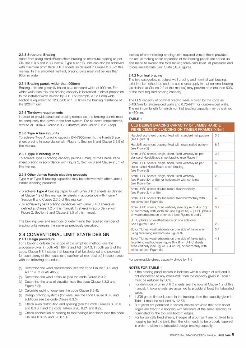
4.2 BRACING RESISTANCE CAPACITYTable 5 shows the bracing capacity of HardieBrace sheet bracing and other James Hardie cladding products when fixed to 0.55mm and 0.75mm light gauge steel frames or 1.2mm and 1.6mm medium gauge, welded steel frames. NOTE Only the values tested are shown in Table 5. Other values may, in certain instances, be interpolated with experience and due diligence. The bracing capacities are achieved by using the fixing methods outlined in Clause 4.4 and Section 8 of this manual. Design capacities were determined in accordance with AS 3623-1993 for 2700mm high panels unless noted otherwise. The minimum length of a bracing wall or panel must be 900mm. The maximum wall length to which the capacities apply is 3600mm.
4.3 FRAMING CONNECTIONS0.55mm to 0.95mm light gauge steel frames: The studs need to be fixed to the top and bottom tracks by screws, rivets, bolts or mechanical crimping. 1.0mm to 1.6mm medium gauge steel frames: The connections may be welded or rivetted, noting that the design bracing capacity is 20% lower for the rivetted frames.
4.4 TIE-DOWN REQUIREMENTS0.55mm to 0.95mm light gauge steel frames: Provide M10 minimum hold-down bolts with 50 x 50 x 3mm distribution washers at the two outside frame studs and M6 minimum hold-down bolts with 32mm diameter 2.5mm thick round washers at the interior studs. All bolts to be placed within 45mm of the stud. 0.95mm to 1.6mm medium gauge steel frames: Provide M12 minimum hold-down bolts with 75 x 70 x 6mm distribution washers at 900mm centres and within 70mm of the face of studs.
NOTES FOR TABLE 51. HardieBrace sheet bracing must not be used as exposed, finished,
external cladding. 2. Bracing capacity can only be claimed for JHFC plank or
weatherboard cladding if screws pass through both planks. See Figure 6.
3. For rivetted frames of 1.2 and 1.6mm gauge, the tabulated bracing capacities must be multiplied by a factor of 0.8.
4. For definition of 6mm JHFC sheets see Clause 1.2 of this manual. Thicker sheets are assumed to provide at least the tabulated value.
5. Butt joints are permitted in vertical sheets provided that both sheet edges are fixed to a nogging with fasteners at the same spacing as nominated for the top and bottom edges.
6. For horizontally fixed sheets: if edges at a butt joint are not fixed to a nogging, then the joint needs to be properly tape-set in order to claim the tabulated design bracing capacity.
7. For external sides of walls, 6mm Villaboard lining must be replaced by properly coated 6mm HardieFlex or 7.5mm HardieTex system.
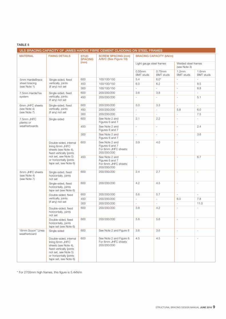
TABLE 5
* For 2700mm high frames, this figure is 5.4kN/m
STRUCTURAL BRACING DESIGN MANUAL JUNE 2016 9
ULS BRACING CAPACITY OF JAMES HARDIE FIBRE CEMENT CLADDING ON STEEL FRAMES
MATERIAL FIXING DETAILS SCREW SPACING (mm) BRACING CAPACITY (kN/m) A/B/C (See Figure 10)
Light gauge steel frames Welded steel frames (see Note 3)
0.55mm 0.75mm 1.2mm 1.6mm BMT studs BMT studs BMT studs BMT studs
600 100/100/150 5.4 6.0* - -
450 100/100/150 6.0 6.2 - 8.5
300 100/100/150 - - - 8.8
600 200/200/200 3.6 3.8 - -
450 200/200/200 - - - 5.1
600 200/200/200 3.0 3.3 - -
450 200/200/200 - - 5.8 6.0
300 200/200/200 - - - 7.5
600 See Note 2 and 2.1 2.2 - - Figures 6 and 7
450 See Note 2 and - - - 2.4 Figures 6 and 7
300 See Note 2 and - - - 3.6 Figures 6 and 7
600 See Note 2 and 3.9 4.0 - - Figures 6 and 7 For 6mm JHFC sheets: 200/200/200
450 See Note 2 and - - - 6.7 Figures 6 and 7 For 6mm JHFC sheets: 200/200/200
600 200/200/200 2.4 2.7 - -
600 200/200/200 4.2 4.5 - -
600 200/200/200 5.6 5.7 - -
450 200/200/200 - - 6.0 7.8
300 200/200/200 - - - 11.0
600 200/200/200 3.8 4.2 - -
600 200/200/200 5.6 5.6 - -
16mm Scyon™ Linea 600 See Note 2 and Figure 8 3.6 3.6 - - weatherboard
600 See Note 2 and Figure 8. 4.5 4.5 - - For 6mm JHFC sheets 200/200/200
STUD SPACING (mm)
5mm HardieBrace sheet bracing (see Note 1)
Single-sided, fixed vertically, joints (if any) not set
7.5mm HardieTex system
Single-sided, fixed vertically, joints (if any) not set
Single-sided, fixed vertically, joints (if any) not set
6mm JHFC sheets (see Note 4) (see Note 7)
7.5mm JHFC planks or weatherboards
Single-sided
Double-sided, internal lining 6mm JHFC sheets (see Note 4), fixed vertically (joints not set, see Note 5) or horizontally (joints tape set, see Note 6)
6mm JHFC sheets (see Note 4) (see Note 7)
Single-sided, fixed horizontally, joints not set
Single-sided, fixed horizontally, joints tape set (see Note 6)
Double-sided, fixed vertically, joints (if any) not set
Double-sided, fixed horizontally, joints not set
Double-sided, fixed horizontally, joints tape set (see Note 6)
Single-sided
Double-sided, internal lining 6mm JHFC sheets (see Note 4), fixed vertically (joints not set, see Note 5) or horizontally (joints tape set, see Note 6)
10 STRUCTURAL BRACING DESIGN MANUAL JUNE 2016
5 SAFE WORKING PRACTICES
WORKING INSTRUCTIONSRefer to recommended safe working practices before starting any cutting or machining of product.
Score and snapScore and snap is a fast and efficient method of cutting James Hardie building products using James Hardie’s special tungsten tipped score and snap knife.
Preferably score on the face side of the product. Score against a straight edge and repeat the action to obtain adequate depth for clean break – normally one third of sheet thickness. Snap upwards to achieve break. Smooth any rough edges with a rasp.
Hand guillotineMake guillotine cut on the off-cut side of line to allow for the thickness of the blade.
Fibreshear An electrically powered, fast, clean and effortless way of cutting James Hardie building products, especially around curves such as archways. Make fibreshear cut on the ‘off-cut’ side of the line to allow for the thickness of the shear.
Scored edge Straight edge
NOTEThe information in this section is relevant for HardieBrace sheet bracing only. For other products refer to the relevant technical specification or installation manual.
WARNING - DO NOT BREATHE DUST AND CUT ONLY IN WELL VENTILATED AREAJames Hardie products contain sand, a source of respirable crystalline silica which is considered by some international authorities to be a cause of cancer from some occupational sources. Breathing excessive amounts of respirable silica dust can also cause a disabling and potentially fatal lung disease called silicosis, and has been linked with other diseases. Some studies suggest smoking may increase these risks. During installation or handling: (1) work in outdoor areas with ample ventilation; (2) minimise dust when cutting by using either ‘score and snap’ knife, fibre cement shears or, where not feasible, use a HardieBladeTM Saw Blade and dust-reducing circular saw attached to a HEPA vacuum; (3) warn others in the immediate area to avoid breathing dust; (4) wear a properly-fitted, approved dust mask or respirator (e.g. P1 or P2) in accordance with applicable government regulations and manufacturer instructions to further limit respirable silica exposures. During clean-up, use HEPA vacuums or wet cleanup methods - never dry sweep. For further information, refer to our installation instructions and Material Safety Data Sheets available at www.jameshardie.com.au. FAILURE TO ADHERE TO OUR WARNINGS, MATERIAL SAFETY DATA SHEETS, AND INSTALLATION INSTRUCTIONS MAY LEAD TO SERIOUS PERSONAL INJURY OR DEATH.
JAMES HARDIE RECOMMENDED SAFE WORKING PRACTICES
CUTTING OUTDOORS 1. Position cutting station so wind will blow dust away from the user or others in working area. 2. Use one of the following methods based on the required cutting rate: Best n Score and snap n Hand guillotine n Fibreshear Better n Dust reducing circular saw equipped with HardieBladeTM Saw Blade and HEPA vacuum extraction. Good n Dust reducing circular saw equipped with HardieBladeTM Saw Blade.
CUTTING INDOORS n Cut only using score and snap, hand guillotine or fibreshears (manual, electric or pneumatic). n Position cutting station in a well-ventilated area.
DRILLING/OTHER MACHINING When drilling or machining you should always wear a P1 or P2 dust mask and warn others in the immediate area.
IMPORTANT NOTES 1. For maximum protection (lowest respirable dust production), James Hardie recommends always using “Best” - level cutting methods where feasible. 2. NEVER use a power saw indoors. 3. NEVER use a circular saw blade that does not carry the HardieBladeTM logo. 4. NEVER dry sweep - Use wet suppression or HEPA vacuum. 5. NEVER use grinders. 6. ALWAYS follow tool manufacturers’ safety recommendations.
P1 or P2 respirators should be used in conjunction with above cutting practices to further reduce dust exposures. Additional exposure information is available at www.jameshardie.com.au to help you determine the most appropriate cutting method for your job requirements. If concern still exists about exposure levels or you do not comply with the above practices, you should always consult a qualified industrial hygienist or contact James Hardie for further information.

STRUCTURAL BRACING DESIGN MANUAL JUNE 2016 11
HardieBladeTM Saw BladeThe HardieBladeTM Saw Blade used with a dust-reducing saw and HEPA vacuum extraction allows for fast, clean cutting of James Hardie fibre cement products. A dust-reducing saw uses a dust deflector or a dust collector which can be connected to a vacuum system. When sawing, clamp a straight-edge to the sheet as a guide and run the saw base plate along the straight edge when making the cut.
HOLE-FORMINGFor smooth clean cut circular holes:n Mark the centre of the hole on the sheet.n Pre-drill a pilot hole.n Using the pilot hole as a guide, cut the hole to the appropriate diameter
with a hole saw fitted to a heavy duty electric drill.
For irregular holes:n Small rectangular or circular holes can be cut by drilling a series of small
holes around the perimeter of the hole then tapping out the waste piece from the sheet face.
n Tap carefully to avoid damage to sheets, ensuring the sheet edges are properly supported.
STORAGE AND HANDLINGTo avoid damage, all James Hardie building products should be stored with edges and corners of the sheets protected from chipping.
James Hardie building products must be installed in a dry state and protected from rain during transport and storage. The product must be laid flat under cover on a smooth level surface clear of the ground to avoid exposure to water, moisture, etc.
QUALITYJames Hardie conducts stringent quality checks to ensure any product manufactured falls within our quality spectrum. It is the responsibility of the builder to ensure the product meets aesthetic requirements before installation. James Hardie will not be responsible for rectifying obvious aesthetic surface variations following installation.

12 STRUCTURAL BRACING DESIGN MANUAL JUNE 2016
6 PRODUCT INFORMATION
NOTEThe information in this section is relevant for HardieBrace sheet bracing only. For other products refer to the relevant technical specification or installation manual.
6.1 GENERALHardieBrace sheet bracing, is a cellulose fibre reinforced cement building product. The basic composition is Portland cement, ground sand, cellulose fibre and water.
HardieBrace sheet bracing is manufactured to AS/NZS 2908.2 ‘Cellulose-Cement Products Part 2: Flat Sheets’ (ISO 8336 ‘Fibre Cement Flat Sheets’).
HardieBrace sheet bracing is classified Type A, Category 2 in accordance with AS/NZS 2908.2 ‘Cellulose-Cement Products’.
For Material Safety Data Sheets (MSDS) visit www.jameshardie.com.au or Ask James Hardie™ on 13 11 03.
6.2 PRODUCT MASSBased on equilibrium moisture content the approximate mass of HardieBrace sheet bracing is 6.7kg/m2.
6.3 DURABILITY6.3.1 Resistance to moisture/rottingHardieBrace sheet bracing has demonstrated resistance to permanent moisture induced deterioration (rotting) by passing the following tests in accordance with AS/NZS2908.2:
n Water permeability (Clause 8.2.2)n Warm water (Clause 8.2.4)n Heat rain (Clause 6.5)n Soak dry (Clause 8.2.5)
6.3.2 Resistance to fireThe HardieBrace sheet bracing is suitable where non-combustible materials are required in accordance with C1.12 of the Building Code of Australia. James Hardie building products have been tested by CSIRO in accordance with AS/NZS 3837 and are classified as conforming to Group 1 material (highest and best result possible), with an average specific extinction area far lower than the permissible 250m2/kg, as referenced in Specification C1.10a of the BCA.
6.3.3 Resistance to termite attackBased on testing completed by CSIRO Division of Forest Products and Ensis Australia James Hardie building products have demonstrated resistance to termite attack.
6.4 ALPINE REGIONSIn regions subject to freeze/thaw conditions, all James Hardie fibre cement external cladding must be installed and painted in the warmer months of the year where the temperature does not create freeze and thaw conditions or paint issues. The cladding must be painted immediately after installation. In addition, fibre cement cladding must not be in direct contact with snow and/or ice build up for extended periods, e.g. external walls in alpine regions subject to snow drifts over winter. Furthermore, a reputable paint manufacturer must be consulted in regards to a suitable product, specifications and warranty. The paint application must not be carried out if the air temperature or the substrate temperature is outside the paint manufacturer’s recommendation including the specified drying temperature range James Hardie external cladding products are tested for resistance to frost in accordance with AS/NZS 2908.2 Clause 8.2.3.

STRUCTURAL BRACING DESIGN MANUAL JUNE 2016 13
7 COMPONENTS
The following checklist describes the components required to install HardieBrace sheet bracing.
Timber or steel framing may be used, but must comply with relevant building regulations and standards and the requirements of this manual. Mass includes timber packing for transport.
Not available in WA. Selling unit: square metre (m2).
HARDIEBRACE SHEET BRACING SIZES (5mm THICKNESS)
Description: square edge, pink sheet.
Mass: 6.7kg/m2
Length (mm): Width (mm): Thickness (mm):
2440 925 5 1225 5
2725 925 5 1225 5
JAMES HARDIE HARDIEBRACE SHEET BRACING COMPONENTS
HardieDriveTM screw For light gauge steel frames 0.75mm to 1.6mm thick 8g x 32mm NOTE: Contact your fastener manufacturer for fasteners with suitable 8g x 40mm corrosion resistance.
HardieBladeTM Saw Blade 185mm poly diamond blade, for fast, clean cutting of James Hardie HardieBladeTM Saw Blade fibre cement. Selling unit: each
JH score and snap knife Tungsten tipped scoring tool for easy cutting.
Fibreshear Electric cutting tool.
COMPONENTS NOT SUPPLIED BY JAMES HARDIE
Fibre cement nail Galvanised nails for timber 2.8mm x 30mm, 2.8mm x 40mm and 2.8mm x 50mm
Buildex FibreTEKS® For light gauge steel frames 0.55 to 0.75mm thick Nº 8 x 20mm ® denotes a registered mark of Buildex
14 STRUCTURAL BRACING DESIGN MANUAL JUNE 2016
8 FRAMING, FIXING AND INSTALLATION DETAILS FOR HARDIEBRACE SHEET BRACING
8.1 GENERALThis section sets out the framing, fixing and installation recommendations for HardieBrace sheet bracing.
For framing, fixing and installation recommendations for other James Hardie cladding products mentioned in this manual, refer to the following manuals:
n Villaboard lining, Versilux lining, PineRidge lining: James Hardie internal lining range Fixing Manual
n HardieTex system: James Hardie HardieTex system Technical Specification
n HardieFlex sheet, PanelClad sheet: James Hardie external cladding Technical Specification
n HardiePlankTM weatherboard: James Hardie external cladding Technical Specification
NOTETo achieve structural bracing using these products, you must use the fastener spacing and hold-down recommendations of this manual instead of those set out in the individual James Hardie fixing manuals.
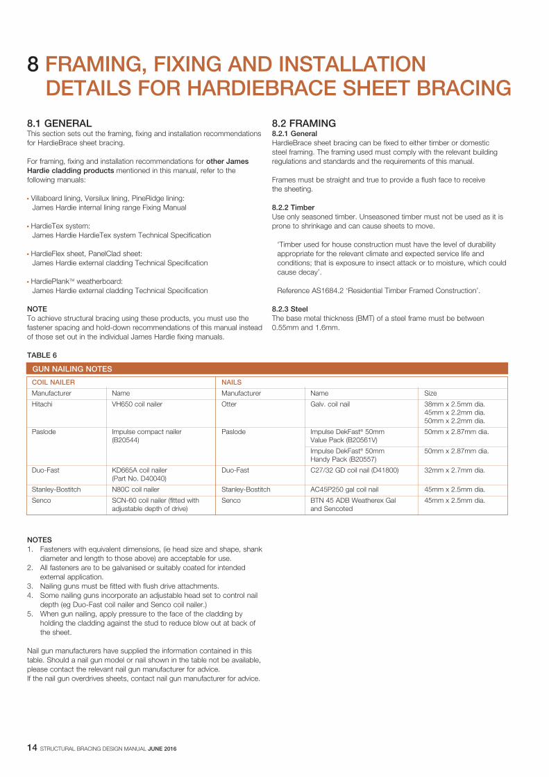
TABLE 6
NOTES1. Fasteners with equivalent dimensions, (ie head size and shape, shank
diameter and length to those above) are acceptable for use.2. All fasteners are to be galvanised or suitably coated for intended
external application.3. Nailing guns must be fitted with flush drive attachments.4. Some nailing guns incorporate an adjustable head set to control nail
depth (eg Duo-Fast coil nailer and Senco coil nailer.)5. When gun nailing, apply pressure to the face of the cladding by
holding the cladding against the stud to reduce blow out at back of the sheet.
Nail gun manufacturers have supplied the information contained in this table. Should a nail gun model or nail shown in the table not be available, please contact the relevant nail gun manufacturer for advice.If the nail gun overdrives sheets, contact nail gun manufacturer for advice.
8.2 FRAMING8.2.1 General HardieBrace sheet bracing can be fixed to either timber or domestic steel framing. The framing used must comply with the relevant building regulations and standards and the requirements of this manual. Frames must be straight and true to provide a flush face to receive the sheeting.
8.2.2 Timber Use only seasoned timber. Unseasoned timber must not be used as it is prone to shrinkage and can cause sheets to move.
‘Timber used for house construction must have the level of durability appropriate for the relevant climate and expected service life and conditions; that is exposure to insect attack or to moisture, which could cause decay’.
Reference AS1684.2 ‘Residential Timber Framed Construction’.
8.2.3 Steel The base metal thickness (BMT) of a steel frame must be between 0.55mm and 1.6mm.
GUN NAILING NOTES
COIL NAILER NAILS
Manufacturer Name Manufacturer Name Size
Hitachi VH650 coil nailer Otter Galv. coil nail 38mm x 2.5mm dia. 45mm x 2.2mm dia. 50mm x 2.2mm dia.
Paslode Impulse compact nailer Paslode Impulse DekFast® 50mm 50mm x 2.87mm dia. (B20544) Value Pack (B20561V)
Impulse DekFast® 50mm 50mm x 2.87mm dia. Handy Pack (B20557)
Duo-Fast KD665A coil nailer Duo-Fast C27/32 GD coil nail (D41800) 32mm x 2.7mm dia. (Part No. D40040)
Stanley-Bostitch N80C coil nailer Stanley-Bostitch AC45P250 gal coil nail 45mm x 2.5mm dia.
Senco SCN-60 coil nailer (fitted with Senco BTN 45 ADB Weatherex Gal 45mm x 2.5mm dia. adjustable depth of drive) and Sencoted

STRUCTURAL BRACING DESIGN MANUAL JUNE 2016 15
8.3 FIXING8.3.1 General You must select a fastener that is suitable for the type of frame you are using.
8.3.2 Fastener corrosion protection Fasteners must have the appropriate level of durability required for the intended project. This is of particular importance in coastal areas, areas subject to salt spray and other corrosive environments.
Fasteners must be fully compatible with all other material that they are in contact with to ensure the durability and integrity of the assembly.
Contact fastener manufacturers for more information. NOTE Fasteners must be at least Class 3 external grade finish.
8.3.3 Fixing depth Nail sheets and boards in accordance with the nailing details shown in this manual. Do not overdrive the nails. Proud nailing is desirable, but flush head nailing is acceptable. See Figure 11. 8.3.4 Fastening to timberUse 2.8 x 30mm hot-dipped galvanised fibre cement nails when hand nailing. HardieBrace sheet bracing can be gun-nailed onto timber frames using flat head nails. Suitable combinations are shown in Table 6.
8.3.5 Fastening to steelFor steel framing of thickness 0.55mm to 0.75mm BMT, 20mm Buildex FibreTEKS self drilling screws. For steel framing of thickness 0.75mm to 1.6mm. Use 8g - 22mm or 8g - 32mm HardieDriveTM external grade screws.
Fasteners should be screwed as close as possible to the stud corners to avoid deflection of the stud flange. See Figure 12.
8.3.6 Screw gun specificationUse variable speed screw guns with high torque, a maximum speed of 2500rpm, fitted with a depth control attachment. Set the depth control attachment to avoid overdriving. As the screw thread begins to pull into the steel frame, drop the revs back to bed the head flush with the surface of the sheet.
8.4 INSTALLATION DETAILS8.4.1 GeneralHardieBrace sheet bracing can be used for cavity bracing in brick veneer construction or internally in locations such as behind built-in full-height cupboards or robes. For fastener spacings and hold-down recommendations, refer in this manual to:
n Clause 2.2 for the simplified design method or Clause 2.3 for the conventional Limit State design method for timber framing;
n Clauses 3.2 and 3.3 for timber framing with cyclone rods;n Figure 10 and Clause 4.4 for steel framing. NOTE HardieBrace sheet bracing must not be used as exposed, finished, external cladding. 8.4.2 Brick tiesBrick ties can be installed through HardieBrace sheet bracing. Simply refer to the hole forming recommendations in Section 5. Ensure the hole is not greater than 50mm diameter through the sheet to allow insertion of brick ties. See Figure 13.

16 STRUCTURAL BRACING DESIGN MANUAL JUNE 2016
12 min.top and bottom
150 max.top and bottom
50min.
12min.
150max.20
0 m
ax.
FIGURE 3 NAILING DETAIL FOR HARDIEFLEX SHEET, PINERIDGE LINING OR PANELCLAD SHEET
12 min.top and bottom
150 max.top and bottom
50min.
12min.
150max.
150
max
.
FIGURE 4 NAILING DETAIL FOR HARDIETEX SYSTEM
NOTE Nails along the top and bottom plates should be 25mm from the edge of the sheet for 50mm thick plates. When 38mm nominal thick plates are used, reduce edge distance to 20mm.
FIGURE 1 TYPE A NAILING DETAIL
FIGURE 2 TYPE B NAILING DETAIL
9 DETAILS

STRUCTURAL BRACING DESIGN MANUAL JUNE 2016 17
NOTEFor details of tiling over these Villaboard linings, refer to the James Hardie Villaboard lining Installation Manual.
12 min.top and bottom
150 max.top and bottom
50min.
12min.
150max.
150
max
.
Flushset jointnoggingbehind
(a) Horizontal
(b) Vertical12 min.
top and bottom150 max.
top and bottom
50min.
12min.
150max.20
0 m
ax.
FIGURE 5 NAILING DETAIL FOR VILLABOARD SHEETS OR VERSILUX LINING
FIGURE 6 NAILING DETAIL FOR HARDIEPLANK
150 max. top and bottom
50 min. at corners
15 min.
30 min. lap
15 min.
FIGURE 7 NAILING SPACING DETAIL FOR JHFC PLANKS OR WEATHERBOARDS
FIGURE 8 NAILING DETAIL FOR LINEA WEATHERBOARDS

18 STRUCTURAL BRACING DESIGN MANUAL JUNE 2016
NOTE HardieBrace sheet bracing will not straighten excessively warped or distorted frames and any warping may be visible after the internal lining is applied.
FIGURE 11 NAIL FASTENER DEPTH
(a) Not recommended (b) Recommended
FIGURE 12 SCREW FASTENING TO STEEL FRAME
FIGURE 13 BRICK TIES
M12 Anchor rod
100 max.
FIGURE 9 ANCHOR ROD DETAIL
12 min.top and bottom
A
50 min.at corners
12 min.
BC
FIGURE 10 SCREW SPACING DETAIL

STRUCTURAL BRACING DESIGN MANUAL JUNE 2016 19
10 WARRANTY
HardieBraceTM sheet bracing
10 Year Warranty
January 2012 James Hardie Australia Pty Limited (“James Hardie”) warrants to the first purchaser of HardieBraceTM sheet bracing (Product) from James Hardie and the last purchaser of the Product prior to installation that, subject to compliance with the Conditions of Warranty below:
- for a period of 10 years from the date of purchase, the Product will be free from defects due to defective factory workmanship or materials; and - for a period of 10 years from the date of purchase, the Product will be resistant to damage from cracking, moisture, rotting, fire and termites to the extent set out in James Hardie’s relevant published literature current at the time of installation; and - for a period of 12 months from the date of purchase that the accessories supplied by James Hardie will be free from defects due to defective factory workmanship or materials.
For the purposes of this warranty, a “defect” in respect of the Product means a non-compliance with AS/NZS 2908.2:2000 Cellulose-cement products - Flat sheet.
CONDITIONS OF WARRANTY This warranty is strictly subject to the following conditions:
(a) James Hardie will not be liable for breach of this warranty unless the claimant provides proof of purchase of the Product and makes a written claim to James Hardie at the address set out below, either within 30 days after the defect would have become reasonably apparent or, if the defect was reasonably apparent prior to installation, then the claim must be made prior to installation.
(b) the Product is subject to natural variation in finish as part of the manufacturing process. The builder/installer must ensure the Product meets aesthetic requirements before installation. Subject to the terms of this warranty, after installation of the Product, James Hardie is not liable for claims arising from aesthetic surface variations if such variations were, or would upon reasonable inspection have been, apparent prior to installation;
(c) this warranty cannot be relied upon by any other person and is not transferable;
(d) the Product must be installed and maintained strictly in accordance with the relevant James Hardie literature current at the time of installation and must be installed in conjunction with the components or products specified in the literature. To obtain copies of such literature go to or contact Ask James Hardie™ on 13 11 03. Further, all other products, including coating and jointing systems, applied to or used in conjunction with the Product must be applied or installed and maintained strictly in accordance with the relevant manufacturer’s instructions and good trade practice;
(e) the project must be designed and constructed in strict compliance with all relevant provisions of the current Building Code of Australia, regulations and standards;
(f) if the claimant chooses to rely upon this warranty then the claimant’s sole remedy under this warranty for breach of this warranty is (at James Hardie’s option) that James Hardie will either supply replacement Product, rectify the affected Product or pay for the cost of the replacement or rectification of the affected Product;
(g) In the circumstances where the Australian Consumer Law does not apply in respect of the purchase of the Product, James Hardie will not be liable for any losses or damages (whether direct or indirect) including property damage or personal injury, consequential loss, economic loss or loss of profits, arising in contract or negligence or howsoever arising. Without limiting the foregoing, James Hardie will not be liable for any claims, damages or defects arising from or in any way attributable to poor workmanship, poor design or detailing, settlement or structural movement and/or movement of materials to which the Product is attached, incorrect design of the structure,
acts of God including but not limited to earthquakes, cyclones, floods or other severe weather conditions or unusual climatic conditions, efflorescence or performance of paint/coatings applied to the Product, normal wear and tear, growth of mould, mildew, fungi, bacteria, or any organism on any Product surface or Product (whether on the exposed or unexposed surfaces);
(h) In the circumstances where the Australian Consumer Law does not apply in respect of the purchase of the Product, all warranties, conditions, liabilities and obligations other than those specified in this warranty are excluded to the fullest extent allowed by law;
(i) If meeting a claim under this warranty involves re-coating of Product, there may be slight colour differences between the original and replacement Product due to the effects of weathering and variations in materials over time and James Hardie is not liable for any such colour differences;
(j) In the circumstances where the Australian Consumer Law does not apply in respect of the purchase of the Product and therefore to this warranty, all expenses incurred as a result of claiming under this warranty are to be borne by the claimant.
(k) In the circumstances where the Australian Consumer Law does apply in respect of the purchase of the Product and therefore to this warranty, if James Hardie accepts or it is determined by James Hardie that the claimant has a valid claim under this warranty, James Hardie will bear the claimant’s reasonable costs of claiming under this warranty. The claimant is responsible for all other costs of claiming under this warranty. All claims for such costs are to be notified to James Hardie at the address outlined below within 21 days from when the claimant first makes a claim under this warranty.
DISCLAIMER The recommendations in James Hardie’s literature are based on good building practice but are not an exhaustive statement of all relevant information and are subject to conditions (d), (e), (g) and (h) above. Further, as the successful performance of the relevant system depends on numerous factors outside the control of James Hardie (e.g. quality of workmanship and design), James Hardie shall not be liable for the recommendations in that literature and the performance of the relevant system, including its suitability for any purpose or ability to satisfy the relevant provisions of the Building Code of Australia, regulations and standards.
IMPORTANT NOTE If you acquire goods manufactured by James Hardie as a consumer according to the Australian Consumer Law, our goods come with guarantees that cannot be excluded under the Australian Consumer Law. You are entitled to a replacement or refund for a major failure and compensation for any other reasonably foreseeable loss or damage. You are also entitled to have the goods repaired or replaced if the goods fail to be of acceptable quality and the failure does not amount to a major failure.
Any rights a consumer may have under this warranty are in addition to other rights and remedies of a consumer under a law in relation to the goods to which this warranty relates. Nothing in this document shall exclude or modify any legal rights a customer may have under the Australian Consumer Law or otherwise which cannot be excluded or modified at law.
Contact details if you wish to make a claim under this warranty: For more information or to make a claim under this warranty please Ask James Hardie™ on 13 11 03, visit www.jameshardie.com.au or www.accel.com.au, email James Hardie via our website or write to James Hardie at: James Hardie Australia Pty Ltd 10 Colquhoun Street Rosehill NSW 2142 PO Box 70 Parramatta NSW 2124
© Copyright 2012 James Hardie Australia Pty Ltd. ABN 12 084 635 558. ™ and ® denotes a trademark or registered mark owned by James Hardie Technology Limited

© Copyright 2012 James Hardie Australia Pty Ltd. ABN 12 084 635 558.TM and ® denotes a trademark or registered mark owned by James Hardie Technology Limited
Front cover image: HPA / Mirvac
JHML112620