Embed Size (px)
Citation preview

Australia Pacific LNG Project Volume 5: Attachments Attachment 46: Marsh Hazard and Risk Assessment - Gas Fields and Pipeline
3 December 2009
Upstream Hazard and Risk Study for the Australia Pacific LNG Project Australia Pacific LNG Pty Limited
Project: APLNG Project
Prepared by: Paul Shardlow, Senior Consultant
John Reid, Senior Consultant
Tom Croese, Senior Consultant
Q/A Review: James Keneally, Managing Principal
File No.: PRC75358
Volume 5: Attachments Attachment 46: Marsh Hazard and Risk Assessment - Gas Fields and Pipeline
Marsh Australia Pacific LNG Project EIS Page i March 2010
i
Contents 1. Executive Summary ................................................................................................... 1
2. Introduction................................................................................................................. 5
2.1 Overview .................................................................................................................... 5
2.2 Scope ......................................................................................................................... 5
2.3 Objectives................................................................................................................... 5
2.4 Atypical, Abnormal and Off-site.................................................................................. 6
2.5 Assessment and Analysis Worst Case Scenario........................................................ 6
2.6 Environmental and Safety Management Plans .......................................................... 6
3. Method ....................................................................................................................... 8
3.1 Hazard and Risk Identification.................................................................................... 8
3.2 Consequence Assessment....................................................................................... 12
3.3 Likelihood Assessment............................................................................................. 14
4. CSG Field Findings .................................................................................................. 15
4.1 Potential Risks Identified .......................................................................................... 15
4.2 Consequence and Likelihood Assessment .............................................................. 18
5. Transmission Pipeline Findings................................................................................ 29
5.1 Potential Risks Identified .......................................................................................... 29
5.2 Consequence and Likelihood Assessment .............................................................. 31
6. Appendices............................................................................................................... 40
Disclaimer This report has been prepared in consultation with Australia Pacific LNG Pty Limited, for whom it was conducted and is based upon the information supplied by the client. The Risk Consulting Practice of Marsh Pty Ltd is unable to vouch for the accuracy of that information and accordingly is unable to warrant the accuracy of the information contained in this Report. Any hazards mentioned or listed are given as examples of similar hazards that may occur elsewhere or as examples of shortcomings in the loss control program. No warranty is given or implied that the risks identified are the only risks facing the Project. This Report and the recommendations contained therein are not intended to be a substitute for appropriate professional advice in dealing with any specific matter. This Report is not intended to replace legal or actuarial advice. Failure to mention any matter that may constitute a breach of statutory obligation does not imply that no such breach occurs. This Report has been prepared for Australia Pacific LNG Pty Limited on a specific and agreed basis and should not be relied upon by any other party.
Volume 5: Attachments Attachment 46: Marsh Hazard and Risk Assessment - Gas Fields and Pipeline
Marsh Australia Pacific LNG Project EIS Page 1 March 2010 1
1
1. Executive Summary
Australian Pacific LNG Limited (APLNG) is proposing to develop a coal seam gas field, gathering system, gas processing facilities including compressor stations in the Surat Basin and a 440 km main transmission pipeline to support a four train LNG Plant at Curtis Island, Queensland. These assets excluding the LNG Plant are referred to as the Upstream facilities.
The Risk Consulting practice of Marsh Pty Ltd (Marsh) was engaged to complete a Hazard and Risk study of risk impacts to people and property due to atypical and/or abnormal processing events for the Upstream facilities during construction, operational and decommissioning phases. This report addresses Section 6.1 in part, of the Terms of Reference for the Environmental Impact Statement for the project which is being coordinated by Worley Parsons.
In summary, this study aims to understand what hazards are present, the magnitude of these hazards and evaluate them against referenced industry criteria. To achieve this, the following process was used:
� Identification of hazards – all processing related hazards were identified through a review of existing Origin risk registers, reference to initial process designs and review of related industry incidents
� Rationalisation of hazards – scenarios were developed to establish credible events that could conceivably impact third parties outside of established boundaries
� Risk quantification – where hazards were significant quantified risk assessment was used to determine the hazard end point and risk as follows:
– Consequence – using a range of models including those presented in AS28851, the possible impact of each scenario was quantified in order to establish the actual extent of the hazard end point
– Likelihood – using related industry data and models, the likelihood of the nominated consequences of occurring was calculated
1 AS 2885.1-2007 Pipelines – Gas and liquid petroleum. Part 1: Design and construction
Volume 5: Attachments Attachment 46: Marsh Hazard and Risk Assessment - Gas Fields and Pipeline
Marsh Australia Pacific LNG Project EIS Page 2 March 2010 2
– Risk contours – through the application of the risk law – Risk = Consequence x Likelihood, risk contours for the nominated hazard end points were established
� Industry comparison – using nominated industry guidelines for major hazard facilities and related infrastructure, in particular HIPAP42, the risk contours were compared to determine if the risks from the project were manageable and/or would materially alter the safety and health exposures of the community over existing levels.
The results of this study for the Upstream facilities have been separated into the following two headings for ease of review:
� CSG Field – inclusive of the coal seam gas (CSG) field, gathering system, gas processing facilities and compressor stations in the Surat Basin
� Transmission Pipeline – main transmission pipeline from the collection facilities through to the boundary of the LNG Plant including all co-location corridors and the crossing over ‘The Narrows’ from the mainland to Curtis Island.
Through the application of this process as described above, the significant hazards identified where quantification was performed are summarised below:
� CSG Field Scenarios
– Release of CSG scenarios
� Uncontrolled release at the well (prior to installation of the well head)
� Rupture of pipe from well head to the separator
� Rupture of pipeline in the gathering system
� Rupture of gas outlet from compressor
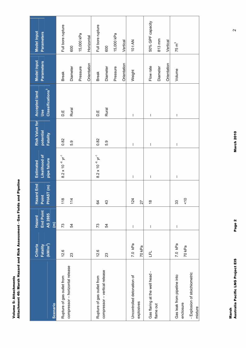
- Conclusion: the worst case scenarios were assessed and the results of the hazard end point and risk values are presented in the summary tables at the end of this section. The findings conclude that while HIPAP4 does not specify a criteria for rural areas (where this infrastructure is mostly located) the risk values are all well within the criteria for industrial zones. This is due to the very low likelihood of these events. Furthermore, with the provision of fenced areas around well heads and gas processing facilities, the only potential risks that extend off-site are those associated with pipeline rupture. High pressure steel pipelines are designed such that rupture is not credible in areas where the risk of third party intervention exists.
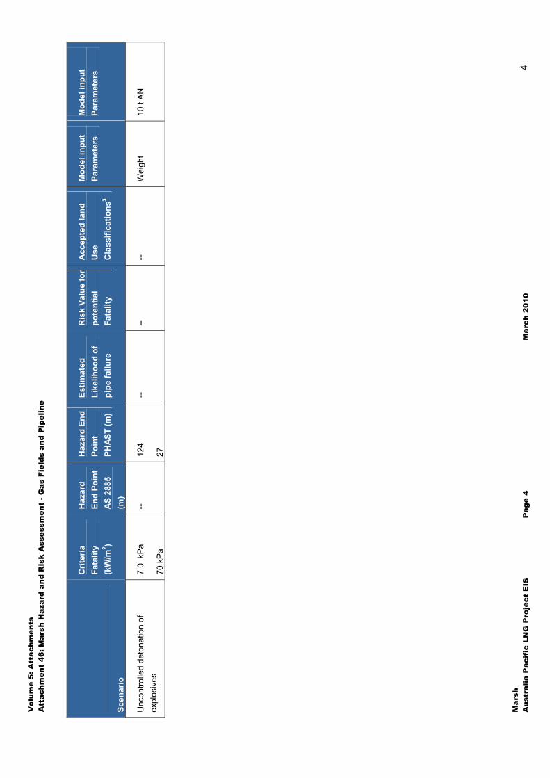
– Uncontrolled detonation of explosives
� Conclusion: The transportation of explosives is managed by the selection of the transport route, storage and handling requirements and selection of a skill and experience contractor. This is a risk that is already present and therefore assumed to be accepted. Note, explosives will only be used during construction for removal of hard rock sections during trenching, and all use of explosives will comply with and approved blasting plan and applicable legislation.
2 Risk Criteria for Land Use Safety Planning – hazardous industry planning advisory (HIPAP) No 4 – Department of Planning Sydney (1992)
Volume 5: Attachments Attachment 46: Marsh Hazard and Risk Assessment - Gas Fields and Pipeline
Marsh Australia Pacific LNG Project EIS Page 3 March 2010 3
– Gas flaring at the well head - flame out
� Conclusion: Flaring is not a scheduled event and in most cases where equipment is taken out of service for maintenance, gas will be diverted to other processing facilities, thus avoiding the need to flare. Therefore, flaring would only occur in the case of unforeseen process deviations which may occur only a few times a year. In addition, this scenario is for the situation where the flare is accidently extinguished resulting in the formation of a flammable gas cloud. It is found that the cloud does not reach ground level and ignition is not a credible event.
– Gas leak and explosion within a compressor enclosure
� Conclusion: there are multiple layers of protection to be employed to prevent this scenario which are inherent in the design of compressor stations. Irrespective of this the fatality hazard end point does not exceed 10 metres which is within the nominated boundary for a Gas Processing Facility.
� Transmission Pipeline Scenarios
– Release of CSG scenarios
– Full bore rupture of pipeline
– Full bore rupture of two co-located pipelines
� Commentary: Full bore rupture of the pipeline is not a credible risk because it is designed as non rupture in accordance with AS 2885.1. Nevertheless, quantified risk assessment of the hazard has been performed for informative purposes and to provide assistance in the determination of location classes in accordance with AS 2885.1. The results are presented in the summary table at the end of this section. Regarding co-located pipelines, AS2885.1 recognises the Common Infrastructure Corridor (CIC) as a secondary location class and specifies that in addition to the primary location class the non rupture design of the pipeline will consider the dominant threats associated with the CIC in regard to land use. Also for high density residential and residential / industrial location classes, the maximum credible release of gas is restricted by design to meet acceptable safety criteria. In conclusion, pipeline risks are made to be acceptable by design in accordance with AS 2885.1.
– Uncontrolled detonation of explosives
� Conclusion: The transportation of explosives is managed by the selection of the transport route, storage and handling requirements and selection of a skill and experience contractor. This is a risk that is already present and therefore assumed to be accepted. Note, explosives will only be used during construction for removal of hard rock sections during trenching, and all use of explosives will comply with and approved blasting plan and applicable legislation.
From these results, the following conclusions can be drawn:
� There were very few risks where the hazard end point extended outside of the nominated site boundaries and are only associated with pipeline rupture
� CSG extraction represents a low risk due to the nature of the extraction pressures involved, particularly in comparison to the pressures that can be experienced with natural gas well heads
Volume 5: Attachments Attachment 46: Marsh Hazard and Risk Assessment - Gas Fields and Pipeline
Marsh Australia Pacific LNG Project EIS Page 4 March 2010 4
� Proposed footprints of the well heads can be reduced from 100 m x 100 m areas and still meet acceptable criteria for individual fatality risk at the boundary
� The pipeline industry track record in Australia indicates that the application of sound engineering design processes, which will be implemented in the execution of this project, will deliver a safe pipeline
� The most significant abnormal or atypical processing failure identified is a failure of the transmission pipeline, however this is not considered to be a credible risk due to the pipeline design being founded on non-rupture principles whereby a catastrophic failure of the pipeline is not reasonably conceived
� Co-location risks for the transmission pipeline have been considered and it is concluded that the potential impact from one pipeline to another is extremely unlikely due to non rupture design and separation distances between pipelines.
Fundamentally, this report concludes that all risks as identified within the following sections are considered to be manageable through the application of AS 2885 and remain well within the criteria suggested by HIPAP4.

Vol
ume
5: A
ttac
hmen
ts
Att
achm
ent
46: M
arsh
Haz
ard
and
Ris
k A
sses
smen
t - G
as F
ield
s an
d P
ipel
ine
Mar
sh
Aus
tral
ia P
acif
ic L
NG
Pro
ject
EIS
P
age
1 M
arch
201
0 1
Sum
mar
y of
CS
G F
ield
Sce
nari
os a
nd R
esul
ts
Scen
ario
Crit
eria
Fa
talit
y (k
W/m
2 )
Haz
ard
End
Poin
t A
S 28
85
(m)
Haz
ard
End
Poin
t PH
AST
(m)
Estim
ated
Li
kelih
ood
of
pipe
failu
re
Ris
k Va
lue
for
pote
ntia
l Fa
talit
y
Acc
epte
d la
nd
Use
C
lass
ifica
tions
3
Mod
el in
put
Para
met
ers
Mod
el in
put
Para
met
ers
Unc
ontro
lled
rele
ase
of n
atur
al
gas
at th
e w
ell h
ead
- prio
r to
inst
alla
tion
of th
e w
ell
head
12.6
23
24
18
19
10
--
-- --
Bre
ak
Dia
met
er
Pre
ssur
e
Orie
ntat
ion
Full
bore
rupt
ure
162
mm
1360
kPa
Ver
tical
Rup
ture
of p
ipe
from
wel
l hea
d to
th
e se
para
tor
12.6
23
23
17
42
39
1 x
10 -1
0 hr-1
0.
09
0.63
B,C
,D,E
Rur
al
Bre
ak
Dia
met
er
Pre
ssur
e
Orie
ntat
ion
Full
bore
rupt
ure
150
mm
1360
kPa
Hor
izon
tal
Rup
ture
of g
athe
ring
syst
em
pipe
line
12.6
23
144
106
98
59
0.02
7x 1
0 -6
m-1
yr
-1
3.2
C, D
, E
Rur
al
Bre
ak
Dia
met
er
Pre
ssur
e
Orie
ntat
ion
Full
bore
rupt
ure
600
1360
kPa
Ver
tical
3 Lan
d U
se C
lass
ifica
tion
codi
ng is
as
follo
ws:
A –
Hos
pita
ls, s
choo
ls, c
hild
car
e fa
cilit
ies,
old
age
hou
sing
; B –
Res
iden
tial,
hote
ls, m
otel
s, to
uris
t res
orts
; C –
Com
mer
cial
de
velo
pmen
ts in
clud
ing
reta
il ce
ntre
s, o
ffice
s an
d en
terta
inm
ent c
entre
s; D
– s
porti
ng c
ompl
exes
and
act
ive
open
spa
ces;
E -
Indu
stria
l
Vol
ume
5: A
ttac
hmen
ts
Att
achm
ent
46: M
arsh
Haz
ard
and
Ris
k A
sses
smen
t - G
as F
ield
s an
d P
ipel
ine
Mar
sh
Aus
tral
ia P
acif
ic L
NG
Pro
ject
EIS
P
age
2 M
arch
201
0 2
Scen
ario
Crit
eria
Fa
talit
y (k
W/m
2 )
Haz
ard
End
Poin
t A
S 28
85
(m)
Haz
ard
End
Poin
t PH
AST
(m)
Estim
ated
Li
kelih
ood
of
pipe
failu
re
Ris
k Va
lue
for
pote
ntia
l Fa
talit
y
Acc
epte
d la
nd
Use
C
lass
ifica
tions
3
Mod
el in
put
Para
met
ers
Mod
el in
put
Para
met
ers
Rup
ture
of g
as o
utle
t fro
m
com
pres
sor –
hor
izon
tal r
elea
se
12.6
23
73
54
118
114
8.2
x 10
-6 y
r-1
0.82
5.9
D,E
Rur
al
Bre
ak
Dia
met
er
Pre
ssur
e
Orie
ntat
ion
Full
bore
rupt
ure
600
15,0
00 k
Pa
Hor
izon
tal
Rup
ture
of g
as o
utle
t fro
m
com
pres
sor –
ver
tical
rele
ase
12
.6
23
73
54
64
43
8.2
x 10
-6 y
r-1
0.82
5.9
D,E
Rur
al
Bre
ak
Dia
met
er
Pre
ssur
e
Orie
ntat
ion
Full
bore
rupt
ure
600
15,0
00 k
Pa
Ver
tical
Unc
ontro
lled
deto
natio
n of
ex
plos
ives
7.
0 k
Pa
70 k
Pa
-- 12
4
27
-- --
-- W
eigh
t 10
t A
N
Gas
flar
ing
at th
e w
ell h
ead
- fla
me
out
LFL
-- 18
--
-- --
Flow
rate
Dia
met
er
Orie
ntat
ion
50%
GP
F ca
paci
ty
813
mm
Ver
tical
Gas
leak
from
pip
elin
e in
to
encl
osur
e
- Exp
losi
on o
f sto
ichi
omet
ric
mix
ture
7.0
kP
a
70 k
Pa
-- 33
<10
-- --
-- V
olum
e 75
m3

Vol
ume
5: A
ttac
hmen
ts
Att
achm
ent
46: M
arsh
Haz
ard
and
Ris
k A
sses
smen
t - G
as F
ield
s an
d P
ipel
ine
Mar
sh
Aus
tral
ia P
acif
ic L
NG
Pro
ject
EIS
P
age
3 M
arch
201
0 3
Sum
mar
y of
Tra
nsm
issi
on P
ipel
ine
Sce
nari
os a
nd R
esul
ts
Scen
ario
Crit
eria
Fa
talit
y (k
W/m
2 )
Haz
ard
End
Poin
t A
S 28
85
(m)
Haz
ard
End
Poin
t PH
AST
(m)
Estim
ated
Li
kelih
ood
of
pipe
failu
re
Ris
k Va
lue
for
pote
ntia
l Fa
talit
y
Acc
epte
d la
nd
Use
C
lass
ifica
tions
3
Mod
el in
put
Para
met
ers
Mod
el in
put
Para
met
ers
Full
bore
rupt
ure
of p
ipel
ine
(und
ergr
ound
sec
tion)
12
.6
23
781
578
396
229
0.00
2 x
10 -6
m-1
yr
-1
0.9
B, C
, D, E
Rur
al
Bre
ak
Dia
met
er
Pre
ssur
e
Orie
ntat
ion
Full
bore
rupt
ure
1067
mm
1500
0 kP
a
Ver
tical
Full
bore
rupt
ure
of p
ipel
ine
(abo
ve g
roun
d se
ctio
n)
12.6
23
781
578
511
388
0.00
2 x
10 -6
m-1
yr
-1
1.6
C, D
, E
Rur
al
Bre
ak
Dia
met
er
Pre
ssur
e
Orie
ntat
ion
Full
bore
rupt
ure
1067
mm
1500
0 kP
a
Hor
izon
tal
Rup
ture
– 1
0 G
J/s
rele
ase
rate
(n
on-r
ural
) 12
.6
23
126
93
83
47
0.00
2 x
10 -6
m-1
yr
-1
0.2
A, B
, C, D
, E
Rur
al
Rel
ease
Rat
e
Orie
ntat
ion
10 G
J/se
c
Ver
tical
Rup
ture
– 1
GJ/
s re
leas
e ra
te
(non
-rur
al)
12.6
23
40
29
28
14
0.00
2 x
10 -6
m-1
yr
-1
0.06
A
, B, C
, D, E
Rur
al
Rel
ease
Rat
e
Orie
ntat
ion
1 G
J/se
c
Ver
tical
Full
bore
rupt
ure
of tw
o co
-loca
ted
pipe
lines
- pip
elin
es o
f the
sam
e ca
paci
ty
12.6
23
1105
818
514
291
0.00
2 x
10 -6
m-1
yr
-1
1.2
B, C
, D, E
Rur
al
Bre
ak
Dia
met
er
Pre
ssur
e
Orie
ntat
ion
Full
bore
rupt
ure
1067
mm
1500
0 kP
a
Ver
tical
Vol
ume
5: A
ttac
hmen
ts
Att
achm
ent
46: M
arsh
Haz
ard
and
Ris
k A
sses
smen
t - G
as F
ield
s an
d P
ipel
ine
Mar
sh
Aus
tral
ia P
acif
ic L
NG
Pro
ject
EIS
P
age
4 M
arch
201
0 4
Scen
ario
Crit
eria
Fa
talit
y (k
W/m
2 )
Haz
ard
End
Poin
t A
S 28
85
(m)
Haz
ard
End
Poin
t PH
AST
(m)
Estim
ated
Li
kelih
ood
of
pipe
failu
re
Ris
k Va
lue
for
pote
ntia
l Fa
talit
y
Acc
epte
d la
nd
Use
C
lass
ifica
tions
3
Mod
el in
put
Para
met
ers
Mod
el in
put
Para
met
ers
Unc
ontro
lled
deto
natio
n of
ex
plos
ives
7.
0 k
Pa
70 k
Pa
-- 12
4
27
-- --
-- W
eigh
t 10
t A
N
Volume 5: Attachments Attachment 46: Marsh Hazard and Risk Assessment - Gas Fields and Pipeline
Marsh Australia Pacific LNG Project EIS Page 5 March 2010 5
2
2. Introduction
2.1 Overview
The purpose of this report is to present the findings of a preliminary Hazard and Risk study of atypical / abnormal risks impacting people and property for the proposed Australian Pacific LNG Limited (APLNG) coal seam gas field, gathering system, gas processing facilities, compressor stations and main transmission pipeline to the LNG plant. The report is in response to Section 6.1 in part, of the Terms of Reference for the Environmental Impact Statement for the project which is being undertaken by Worley Parsons and therefore should be read as part of the full EIS which includes a full project description and complete risk register.
2.2 Scope
The scope of this assessment includes the CSG field, gathering system, gas processing facilities, compressor stations and main transmission pipeline up to the boundary of the LNG Plant. The assessment does not include the LNG Plant nor shipping or marine transport activities. The assessment considers potential hazards during construction, operations and decommissioning.
2.3 Objectives
The objectives of this assessment are to:
� Identify potential hazards and risks due to atypical and abnormal scenarios associated with the CSG field, gathering system, gas processing facilities, compressor stations and main transmission pipeline during construction, operations and de-commissioning;
� Evaluate and rank the hazards and risks in accordance with Origin’s risk assessment guidelines;
� Perform a quantitative risk analysis for scenarios where there is a significant hazard represented. This particularly applies to risks that are considered to have off-site impacts with the potential to impact third party people and property by heat radiation, explosion overpressure or toxicity;
Volume 5: Attachments Attachment 46: Marsh Hazard and Risk Assessment - Gas Fields and Pipeline
Marsh Australia Pacific LNG Project EIS Page 6 March 2010 6
� Demonstrate that prevention and mitigation of the potential hazards will be properly addressed in the project design specifications.
Best practice chemical engineering dictates that hazards with extreme potential life safety impacts must be managed at the design stage to ensure that the risk is limited by inherently safe design. To this end, the modelling used in this study will be used as an input into the final design. Therefore, while safety management procedures and emergency management plans are important in the complete management of risk, the focus of this hazard and risk assessment is to prevent the risk in the first instance.
2.4 Atypical, Abnormal and Off-site
Atypical / abnormal scenarios are considered to be due to events that could potentially occur that are not part of normal and expected operations. Off-site impacts are those that extend beyond the boundaries of the proposed, CSG field, gathering system, gas processing facilities compressor station and main transmission pipeline or other physically protected areas of operation.
2.5 Assessment and Analysis Worst Case Scenario
For the purpose of assessing the potential impacts in this study, the worst case consequence is always assumed. This means that the scenarios being assessed are often not credible but for the purpose of assessing a potential hazard to the limit of its potential impact this is the method that has been used. In this way, if it can be shown that the limiting scenario (in terms of consequence, although perhaps not credible) meets acceptable safety criteria then all other lesser potential impacts are covered under this worst case consequence event. For example, a minor hazard such as small fire may be the cause of process equipment failure which ultimately leads to a loss of containment resulting in a much larger fire involving release of CSG. In this case the release of CSG to the full extent possible would be assessed in our analysis, which naturally covered all other contributory incidents. The potential effects of natural hazards are considered in a similar way. That is, an earthquake may cause a pipe failure which leads to a loss of containment and much larger fire involving CSG. Again the worst case scenario is presented and assessed to ensure that the hazards are inherently limited by design.
Furthermore, even though most of the pipeline and CSG field are located in rural areas, acceptance criteria for risk events have been taken from HIPAP 4, which is normally applied in commercial development areas, including industrial and residential zones.
2.6 Environmental and Safety Management Plans
2.6.1 Safety Management Plans
For this study the term Environmental Management Plans as per the Environmental Impact Study’s Terms of Reference is taken to refer to Safety Management Plans in the context of Hazard and Risk. At this stage of the project there are no Safety Management Plans as they will be developed during the engineering stage of the project which is the next stage of the design.
Volume 5: Attachments Attachment 46: Marsh Hazard and Risk Assessment - Gas Fields and Pipeline
Marsh Australia Pacific LNG Project EIS Page 7 March 2010 7
2.6.2 Safety Management Systems and Governance
APLNG, as an owner operator of a gas field and pipeline, will be primarily governed by the Petroleum and Gas (Production and Safety) Act 2004 and petroleum authorities issued under this Act. The proponent will be required to demonstrate adequate safety management prior to commissioning any operating plant. Fundamental to achieving adequate safety management is the development of a Safety Management Study as per AS 2885.1.
A Safety Management Study for this project is currently underway. However the rigour that is required necessitates that this study is undertaken in coordination with detailed design and is an iterative process. Therefore the Safety Management Study at this stage is preliminary.
2.6.3 Project Risk Activities
There is a deliberate effort and commitment by APLNG to design a CSG field and transmission pipeline that is inherently safe. The first step in this process is to conduct a preliminary hazard analysis to identify potential atypical / abnormal risks and identify mitigation strategies for consideration in the design stages of the project. The preliminary hazard analysis is only the first of many risk assessments APLNG will undertake to capture and treat the various risks associated with the project. Appendix A provides more detail of the specific approach that APLNG will take to deliver process safety.
Volume 5: Attachments Attachment 46: Marsh Hazard and Risk Assessment - Gas Fields and Pipeline
Marsh Australia Pacific LNG Project EIS Page 8 March 2010 8
3
3. Method
This section describes the method that has been used to identify potential hazards and quantify the risk.
The aim of the process of identifying potential hazards as described in the following subsection is to establish a table of potential hazards associated with the Upstream pipeline network.
The potential hazards identified are then assessed in terms of the potential consequences that can occur. Our approach to assessing the consequence is to initially evaluate each scenario on worst case circumstances. In this case, where the consequences are found to be within reasonable acceptance criteria it is shown that even at the limit of worst case circumstances, safety is manageable even if a particular scenario is deemed to be not credible.
For each scenario, an assessment of the credibility is made and the likelihood of potential events.
Details of the method of identification, consequence assessment and likelihood assessment are as follows.
3.1 Hazard and Risk Identification
The process of identifying hazards and risks in this study has involved the following systematic approach:
� Understand the properties and characteristics of CSG and the associated material hazards
� Research the background on gas pipeline safety and events that have occurred in the past
� Undertake a risk identification workshop specific to the project
� Review and capture applicable risks from Origin’s existing risk registers
The properties and characteristics of CSG and the background to pipeline safety are discussed in the following subsections.
Volume 5: Attachments Attachment 46: Marsh Hazard and Risk Assessment - Gas Fields and Pipeline
Marsh Australia Pacific LNG Project EIS Page 9 March 2010 9
In accordance with the requirements of Australian Standard for gas and liquid petroleum pipelines (AS 2885.1 2007) an initial qualitative risk assessment of all hazards was performed and a comprehensive risk register prepared (referred to as the Upstream Hazard and Risk Register).
APLNG’s nominated risk assessment guidelines were used to complete the preliminary hazard analysis. In accordance to the scope, the preliminary hazard analysis identified risks that had the potential to impact off-site people and property. Following this, each hazard was reviewed and where the underlying root cause was due to or emanated from atypical and/or abnormal circumstances, it was identified for further analysis.
The hazard identification process was completed using desktop assessment techniques and referencing existing risk registers developed by Origin for Upstream development and operations similar in nature to the proposed project. A cross check with Worley Parsons was also completed to ensure all principal hazards were identified.
3.1.1 Properties of CSG
The analysis of the CSG for this project shows that the methane content is >97%. This is similar to that of natural gas. The physical and chemical properties of CSG (primarily methane) necessitate the very high standard of safety measures. CSG vapours are harder to ignite than other types of flammable liquid fuels because of its relatively high energy requirement for ignition. Above approximately -110oC CSG is lighter than air. If CSG is released into the atmosphere and the resulting flammable mixture in air does not encounter an ignition source, it will rise and dissipate into the atmosphere. The lower and upper flammability limits of CSG are 5% and 15% in air. If the concentration of CSG in air is less than 5% the gas mixture is too dilute to burn and if it is greater than 15% there is not enough oxygen for it to burn.
Given the assay of the CSG for this project, it is odourless, non-toxic, non-corrosive. However CSG is an asphyxiant.
CSG is compressible and a release of high pressure CSG would result in localised sub-zero temperatures due to expansion to atmospheric pressure.
For there to be a fire involving CSG, the conditions of the release, surrounding environment and atmospheric conditions need to be conducive to formulating a flammable gas mixture and a source of ignition co-located with the flammable gas mixture.
The types of fires that can result from a release of CSG depend on the way in which it is released. For CSG the types of fires that can occur are flames, jet flame fires, flash fires and vapour cloud explosions (VCE).
A boiling liquid expanding vapour explosion (BLEVE) is not part of this study as there is no liquefied CSG in the CSG field or transmission pipeline, and therefore a BLEVE is not a credible scenario in the Upstream project. A brief description of the concept is included below for completeness only.
Flame Fire
In the case of a fire from a release of CSG which is ignited at low pressure and low velocity the fire will ordinarily yield standard combustion and flame conditions.
Volume 5: Attachments Attachment 46: Marsh Hazard and Risk Assessment - Gas Fields and Pipeline
Marsh Australia Pacific LNG Project EIS Page 10 March 2010 10
Jet Flame Fire
A jet flame fire occurs when CSG is released under pressure and ignites immediately to form a jet flame from the point of release. A jet flame fire exhibits the characteristic of a directional flame which will impinge on anything in its trajectory and radiate heat.
Vapour Cloud Explosion (VCE) and Flash Fires
A VCE occurs when CSG is released and not instantaneously ignited so that it can form a cloud of vapour. To form a vapour cloud, the rate of release, environmental surroundings and atmospheric conditions need to be conducive to promote a vapour cloud within the limits of flammability. In the open air, a large quantity of flammable vapour is needed for an explosion to occur (i.e. typically more than 5 tonnes), which necessitates a very rapid rate release to achieve such a large cloud within its flammability limits. Such a release would be possible only from the rupture of a sufficiently large and high pressure gas pipeline, or from a loss of containment of CSG stored at a temperature above its normal atmospheric pressure boiling point so it would flash off into the atmosphere. Research during the 1980’s in the U.K. and elsewhere on large clouds, suggests strongly that a cloud of most types of flammable vapour mixed with air will not explode if truly unconfined and unobstructed, no matter how large it is. If however, there is a presence of obstacles (e.g. plant infrastructure), this leads to explosive rates of combustion in their vicinity. It also suggested that the flame front slows down once it is clear of the obstacles, (Tweeddale, 1998). If an explosion does occur, the hazard relates to the overpressure generated from the flame front. While the pressure developed by a VCE in the open air does not usually rise sufficiently to be lethal to people directly, the overpressure causes fatalities by collapsing infrastructure, projecting fragments of broken infrastructure, displacing people into solid objects and enveloping people in the burning cloud. Therefore, except for the conditions conducive to a VCE, a vapour cloud of CSG within the flammability limits would result in a flash fire but not an explosion should an ignition source be available.
Boiling Liquid Expanding Vapour Explosion (BLEVE)
A BLEVE occurs if a pressurised vessel of LNG is involved in a fire. Due to direct impingement of a fire on the vessel, the liquid inside boils and over pressurises the vessel. The vessel is at the same time weakened (above the boiling liquid level) by the external fire and a sudden rupture of the vessel containing LNG occurs. This results in the projection of fragments of the ruptured vessel in the first instance followed by a fire ball from the intense combustion of the turbulent mixture of escaped LNG vapour and liquid with air.
3.1.2 Plant and Pipeline Incidents
Natural gas has been safely handled for many years. There has never been a death or injury recorded in connection with damage to a pipeline in Australia (Tuft, 2009). The industry is not without its incidents and accidents, but it maintains an excellent safety record as a result of the high standards adopted in the design and management standards of present day pipelines and facilities.
In the last decade there have been very few gas pipeline ruptures unrelated to vandalism, (where there have been a number of pipeline explosions in Nigeria due to vandalism). The two most memorable pipeline failures include the Varanus Island gas plant explosion in 2008 and the pipeline explosion in Belgium in 2004.
Volume 5: Attachments Attachment 46: Marsh Hazard and Risk Assessment - Gas Fields and Pipeline
Marsh Australia Pacific LNG Project EIS Page 11 March 2010 11
Belgium, 2004: A pipeline rupture event occurred in 2004 in Belgium resulting in the deaths of 24 people and over 132 injuries. This involved two co-located gas pipelines of 900 mm and 1000 mm operating between pressures of 50 and 80 bar.
Varanus Island, 2008: An explosion at Apaches Varanus Island gas plant in WA cut off 30% of the state’s domestic gas supply in 2008. Supplies to mines and industry in the Pilbara region fell by 45%. The WA Chamber of Commerce and Industry estimates the crisis will have cost the state $6.7 billion.
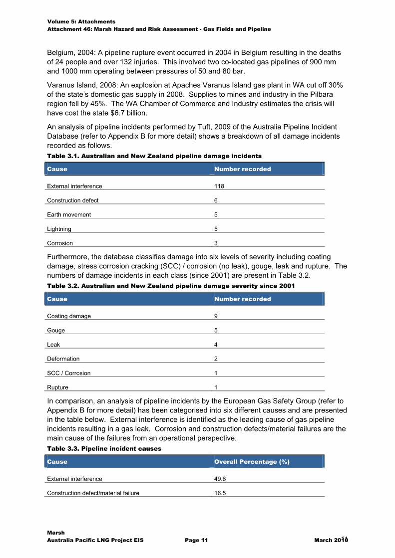
An analysis of pipeline incidents performed by Tuft, 2009 of the Australia Pipeline Incident Database (refer to Appendix B for more detail) shows a breakdown of all damage incidents recorded as follows. Table 3.1. Australian and New Zealand pipeline damage incidents
Cause Number recorded
External interference 118
Construction defect 6
Earth movement 5
Lightning 5
Corrosion 3
Furthermore, the database classifies damage into six levels of severity including coating damage, stress corrosion cracking (SCC) / corrosion (no leak), gouge, leak and rupture. The numbers of damage incidents in each class (since 2001) are present in Table 3.2. Table 3.2. Australian and New Zealand pipeline damage severity since 2001
Cause Number recorded
Coating damage 9
Gouge 5
Leak 4
Deformation 2
SCC / Corrosion 1
Rupture 1
In comparison, an analysis of pipeline incidents by the European Gas Safety Group (refer to Appendix B for more detail) has been categorised into six different causes and are presented in the table below. External interference is identified as the leading cause of gas pipeline incidents resulting in a gas leak. Corrosion and construction defects/material failures are the main cause of the failures from an operational perspective. Table 3.3. Pipeline incident causes
Cause Overall Percentage (%)
External interference 49.6
Construction defect/material failure 16.5
Volume 5: Attachments Attachment 46: Marsh Hazard and Risk Assessment - Gas Fields and Pipeline
Marsh Australia Pacific LNG Project EIS Page 12 March 2010 12
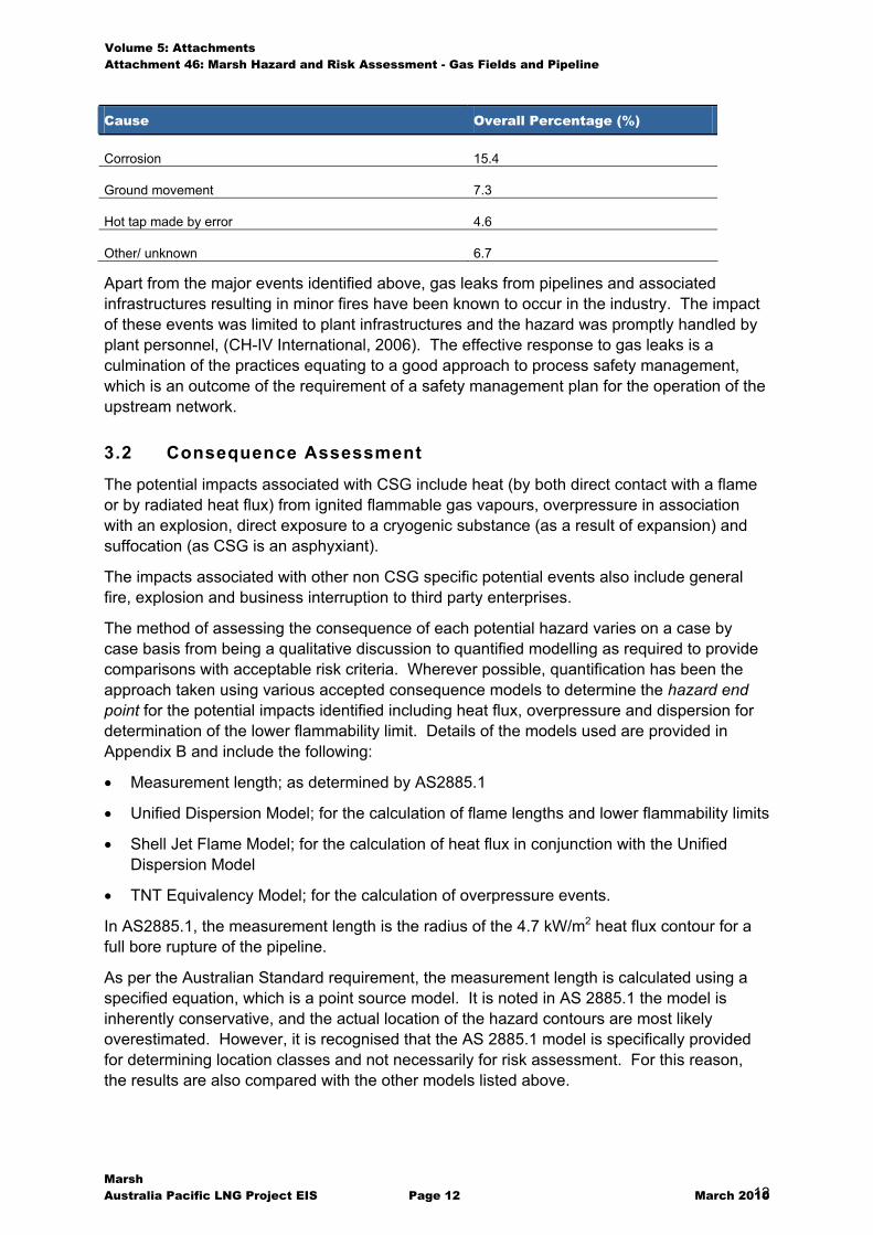
Cause Overall Percentage (%)
Corrosion 15.4
Ground movement 7.3
Hot tap made by error 4.6
Other/ unknown 6.7
Apart from the major events identified above, gas leaks from pipelines and associated infrastructures resulting in minor fires have been known to occur in the industry. The impact of these events was limited to plant infrastructures and the hazard was promptly handled by plant personnel, (CH-IV International, 2006). The effective response to gas leaks is a culmination of the practices equating to a good approach to process safety management, which is an outcome of the requirement of a safety management plan for the operation of the upstream network.
3.2 Consequence Assessment
The potential impacts associated with CSG include heat (by both direct contact with a flame or by radiated heat flux) from ignited flammable gas vapours, overpressure in association with an explosion, direct exposure to a cryogenic substance (as a result of expansion) and suffocation (as CSG is an asphyxiant).
The impacts associated with other non CSG specific potential events also include general fire, explosion and business interruption to third party enterprises.
The method of assessing the consequence of each potential hazard varies on a case by case basis from being a qualitative discussion to quantified modelling as required to provide comparisons with acceptable risk criteria. Wherever possible, quantification has been the approach taken using various accepted consequence models to determine the hazard end point for the potential impacts identified including heat flux, overpressure and dispersion for determination of the lower flammability limit. Details of the models used are provided in Appendix B and include the following:
� Measurement length; as determined by AS2885.1
� Unified Dispersion Model; for the calculation of flame lengths and lower flammability limits
� Shell Jet Flame Model; for the calculation of heat flux in conjunction with the Unified Dispersion Model
� TNT Equivalency Model; for the calculation of overpressure events.
In AS2885.1, the measurement length is the radius of the 4.7 kW/m2 heat flux contour for a full bore rupture of the pipeline.
As per the Australian Standard requirement, the measurement length is calculated using a specified equation, which is a point source model. It is noted in AS 2885.1 the model is inherently conservative, and the actual location of the hazard contours are most likely overestimated. However, it is recognised that the AS 2885.1 model is specifically provided for determining location classes and not necessarily for risk assessment. For this reason, the results are also compared with the other models listed above.
Volume 5: Attachments Attachment 46: Marsh Hazard and Risk Assessment - Gas Fields and Pipeline
Marsh Australia Pacific LNG Project EIS Page 13 March 2010 13
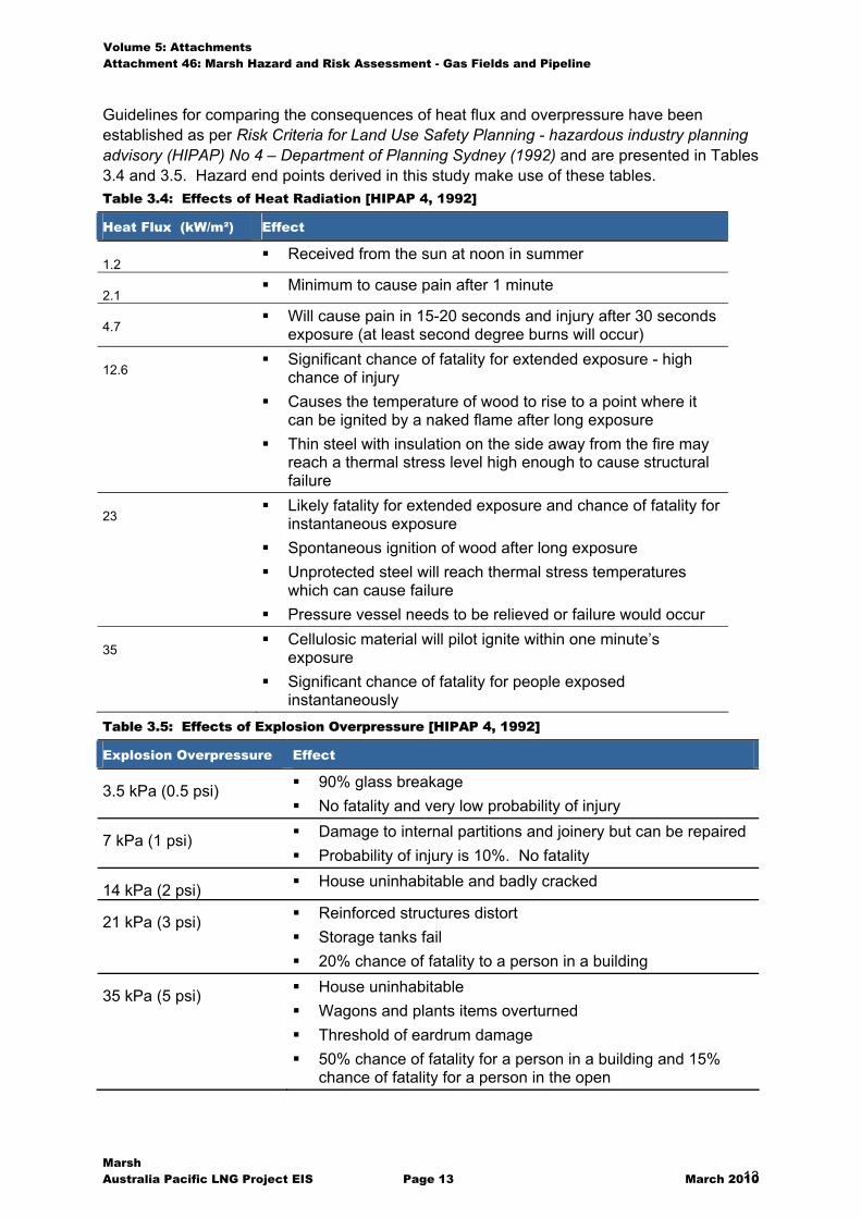
Guidelines for comparing the consequences of heat flux and overpressure have been established as per Risk Criteria for Land Use Safety Planning - hazardous industry planning advisory (HIPAP) No 4 – Department of Planning Sydney (1992) and are presented in Tables 3.4 and 3.5. Hazard end points derived in this study make use of these tables. Table 3.4: Effects of Heat Radiation [HIPAP 4, 1992]
Heat Flux (kW/m²) Effect
1.2 � Received from the sun at noon in summer
2.1 � Minimum to cause pain after 1 minute
4.7 � Will cause pain in 15-20 seconds and injury after 30 seconds
exposure (at least second degree burns will occur)
12.6 � Significant chance of fatality for extended exposure - high
chance of injury � Causes the temperature of wood to rise to a point where it
can be ignited by a naked flame after long exposure � Thin steel with insulation on the side away from the fire may
reach a thermal stress level high enough to cause structural failure
23 � Likely fatality for extended exposure and chance of fatality for
instantaneous exposure � Spontaneous ignition of wood after long exposure � Unprotected steel will reach thermal stress temperatures
which can cause failure � Pressure vessel needs to be relieved or failure would occur
35 � Cellulosic material will pilot ignite within one minute’s
exposure � Significant chance of fatality for people exposed
instantaneously Table 3.5: Effects of Explosion Overpressure [HIPAP 4, 1992]
Explosion Overpressure Effect
3.5 kPa (0.5 psi) � 90% glass breakage � No fatality and very low probability of injury
7 kPa (1 psi) � Damage to internal partitions and joinery but can be repaired � Probability of injury is 10%. No fatality
14 kPa (2 psi) � House uninhabitable and badly cracked
21 kPa (3 psi) � Reinforced structures distort � Storage tanks fail � 20% chance of fatality to a person in a building
35 kPa (5 psi) � House uninhabitable � Wagons and plants items overturned � Threshold of eardrum damage � 50% chance of fatality for a person in a building and 15%
chance of fatality for a person in the open
Volume 5: Attachments Attachment 46: Marsh Hazard and Risk Assessment - Gas Fields and Pipeline
Marsh Australia Pacific LNG Project EIS Page 14 March 2010 14
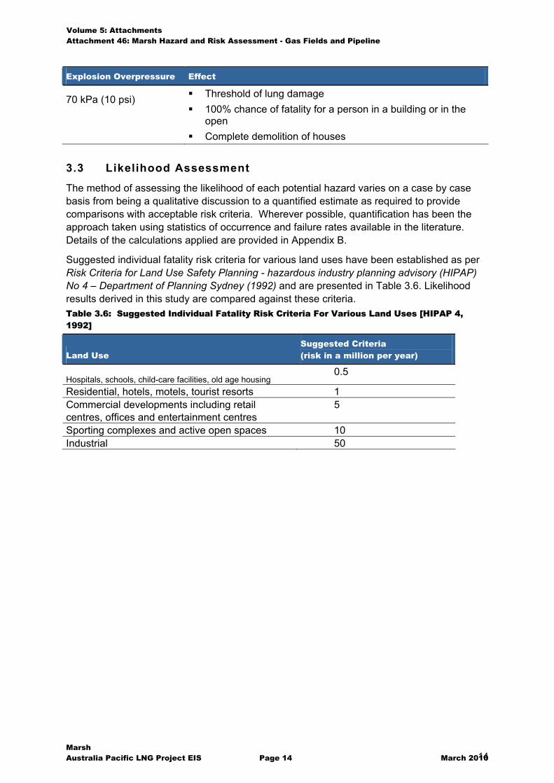
Explosion Overpressure Effect
70 kPa (10 psi) � Threshold of lung damage � 100% chance of fatality for a person in a building or in the
open � Complete demolition of houses
3.3 Likelihood Assessment
The method of assessing the likelihood of each potential hazard varies on a case by case basis from being a qualitative discussion to a quantified estimate as required to provide comparisons with acceptable risk criteria. Wherever possible, quantification has been the approach taken using statistics of occurrence and failure rates available in the literature. Details of the calculations applied are provided in Appendix B.
Suggested individual fatality risk criteria for various land uses have been established as per Risk Criteria for Land Use Safety Planning - hazardous industry planning advisory (HIPAP) No 4 – Department of Planning Sydney (1992) and are presented in Table 3.6. Likelihood results derived in this study are compared against these criteria. Table 3.6: Suggested Individual Fatality Risk Criteria For Various Land Uses [HIPAP 4, 1992]
Land Use Suggested Criteria (risk in a million per year)
Hospitals, schools, child-care facilities, old age housing 0.5
Residential, hotels, motels, tourist resorts 1 Commercial developments including retail centres, offices and entertainment centres
5
Sporting complexes and active open spaces 10 Industrial 50
Volume 5: Attachments Attachment 46: Marsh Hazard and Risk Assessment - Gas Fields and Pipeline
Marsh Australia Pacific LNG Project EIS Page 15 March 2010 15
4
4. CSG Field Findings
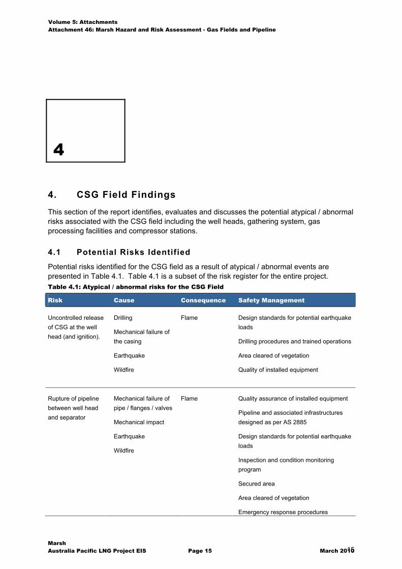
This section of the report identifies, evaluates and discusses the potential atypical / abnormal risks associated with the CSG field including the well heads, gathering system, gas processing facilities and compressor stations.
4.1 Potential Risks Identified
Potential risks identified for the CSG field as a result of atypical / abnormal events are presented in Table 4.1. Table 4.1 is a subset of the risk register for the entire project. Table 4.1: Atypical / abnormal risks for the CSG Field
Risk Cause Consequence Safety Management
Uncontrolled release of CSG at the well head (and ignition).
Drilling
Mechanical failure of the casing
Earthquake
Wildfire
Flame Design standards for potential earthquake loads
Drilling procedures and trained operations
Area cleared of vegetation
Quality of installed equipment
Rupture of pipeline between well head and separator
Mechanical failure of pipe / flanges / valves
Mechanical impact
Earthquake
Wildfire
Flame Quality assurance of installed equipment
Pipeline and associated infrastructures designed as per AS 2885
Design standards for potential earthquake loads
Inspection and condition monitoring program
Secured area
Area cleared of vegetation
Emergency response procedures

Volume 5: Attachments Attachment 46: Marsh Hazard and Risk Assessment - Gas Fields and Pipeline
Marsh Australia Pacific LNG Project EIS Page 16 March 2010 16
Risk Cause Consequence Safety Management
Rupture of high pressure gas outlet from compressor
Mechanical failure of pipe / flanges / valves
Mechanical impact
Earthquake
Wildfire
Jet Flame Quality assurance of installed equipment
Pipeline and associated infrastructures designed as per AS 2885
Non rupture pipe design
Design standards for potential earthquake loads
Inspection and condition monitoring program
Remote monitoring of pressure and flow
Remotely operated isolation valves
Non return valves for stopping back flow
Secured area
Area cleared of vegetation
Emergency response procedures
Rupture of gathering pipe system
Excavation
Earthquake
Corrosion
Jet Flame Pipeline designed as per AS 2885
Selection and placement of pipeline easement
Materials of construction
Non rupture pipe for high pressure steel sections
Design standards for potential earthquake loads
Depth of cover
Pipeline markers and signage
Remote monitoring of pressure and flow
Remotely operated isolation at mid line valves
Emergency response procedures
Uncontrolled detonation of explosives
Road accident
Overcharge
Misfire
Explosion Qualified explosives operator
Designed routes for transportation of dangerous goods
Gas flaring / flame out Control system failure
Mechanical failure
Flash fire Separation
Height of stack
Emergency response procedures
Volume 5: Attachments Attachment 46: Marsh Hazard and Risk Assessment - Gas Fields and Pipeline
Marsh Australia Pacific LNG Project EIS Page 17 March 2010 17
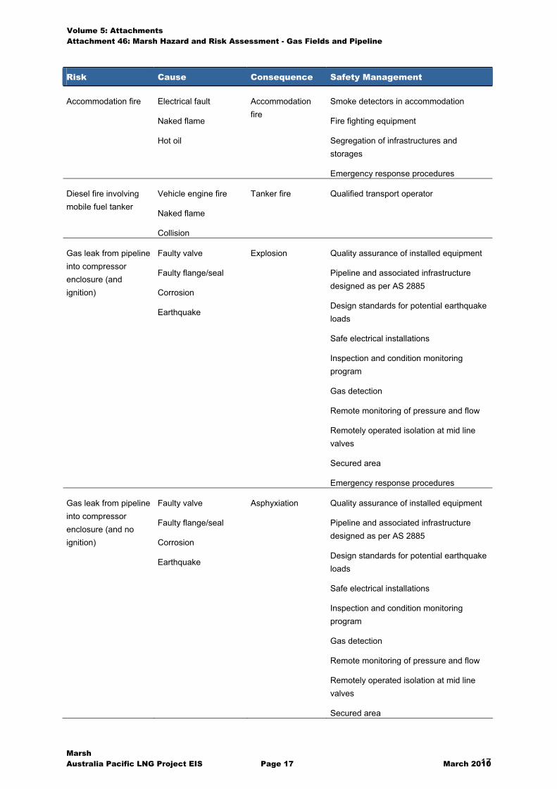
Risk Cause Consequence Safety Management
Accommodation fire Electrical fault
Naked flame
Hot oil
Accommodation fire
Smoke detectors in accommodation
Fire fighting equipment
Segregation of infrastructures and storages
Emergency response procedures
Diesel fire involving mobile fuel tanker
Vehicle engine fire
Naked flame
Collision
Tanker fire Qualified transport operator
Gas leak from pipeline into compressor enclosure (and ignition)
Faulty valve
Faulty flange/seal
Corrosion
Earthquake
Explosion Quality assurance of installed equipment
Pipeline and associated infrastructure designed as per AS 2885
Design standards for potential earthquake loads
Safe electrical installations
Inspection and condition monitoring program
Gas detection
Remote monitoring of pressure and flow
Remotely operated isolation at mid line valves
Secured area
Emergency response procedures
Gas leak from pipeline into compressor enclosure (and no ignition)
Faulty valve
Faulty flange/seal
Corrosion
Earthquake
Asphyxiation Quality assurance of installed equipment
Pipeline and associated infrastructure designed as per AS 2885
Design standards for potential earthquake loads
Safe electrical installations
Inspection and condition monitoring program
Gas detection
Remote monitoring of pressure and flow
Remotely operated isolation at mid line valves
Secured area
Volume 5: Attachments Attachment 46: Marsh Hazard and Risk Assessment - Gas Fields and Pipeline
Marsh Australia Pacific LNG Project EIS Page 18 March 2010 18
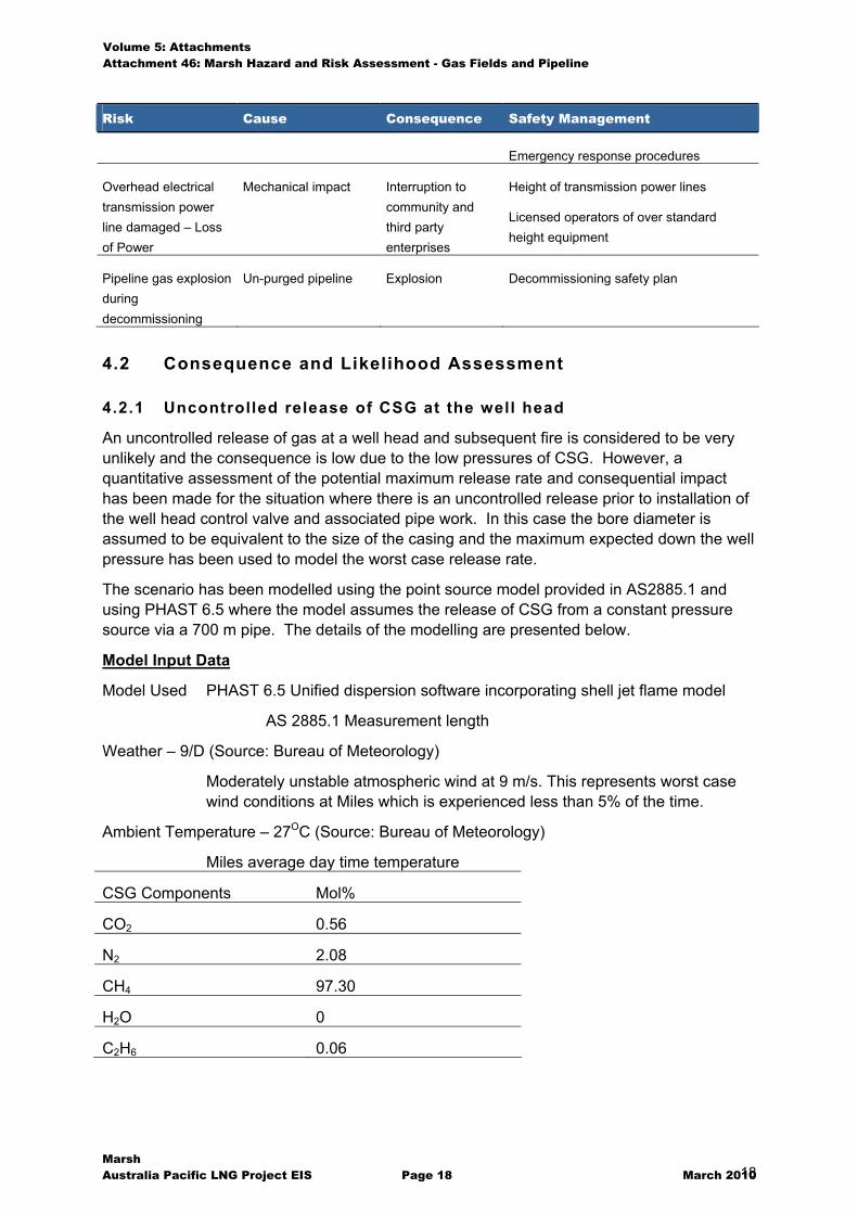
Risk Cause Consequence Safety Management
Emergency response procedures
Overhead electrical transmission power line damaged – Loss of Power
Mechanical impact Interruption to community and third party enterprises
Height of transmission power lines
Licensed operators of over standard height equipment
Pipeline gas explosion during decommissioning
Un-purged pipeline Explosion Decommissioning safety plan
4.2 Consequence and Likelihood Assessment
4.2.1 Uncontrolled release of CSG at the well head
An uncontrolled release of gas at a well head and subsequent fire is considered to be very unlikely and the consequence is low due to the low pressures of CSG. However, a quantitative assessment of the potential maximum release rate and consequential impact has been made for the situation where there is an uncontrolled release prior to installation of the well head control valve and associated pipe work. In this case the bore diameter is assumed to be equivalent to the size of the casing and the maximum expected down the well pressure has been used to model the worst case release rate.
The scenario has been modelled using the point source model provided in AS2885.1 and using PHAST 6.5 where the model assumes the release of CSG from a constant pressure source via a 700 m pipe. The details of the modelling are presented below.
Model Input Data
Model Used PHAST 6.5 Unified dispersion software incorporating shell jet flame model
AS 2885.1 Measurement length
Weather – 9/D (Source: Bureau of Meteorology)
Moderately unstable atmospheric wind at 9 m/s. This represents worst case wind conditions at Miles which is experienced less than 5% of the time.
Ambient Temperature – 27OC (Source: Bureau of Meteorology)
Miles average day time temperature
CSG Components Mol%
CO2 0.56
N2 2.08
CH4 97.30
H2O 0
C2H6 0.06
Volume 5: Attachments Attachment 46: Marsh Hazard and Risk Assessment - Gas Fields and Pipeline
Marsh Australia Pacific LNG Project EIS Page 19 March 2010 19
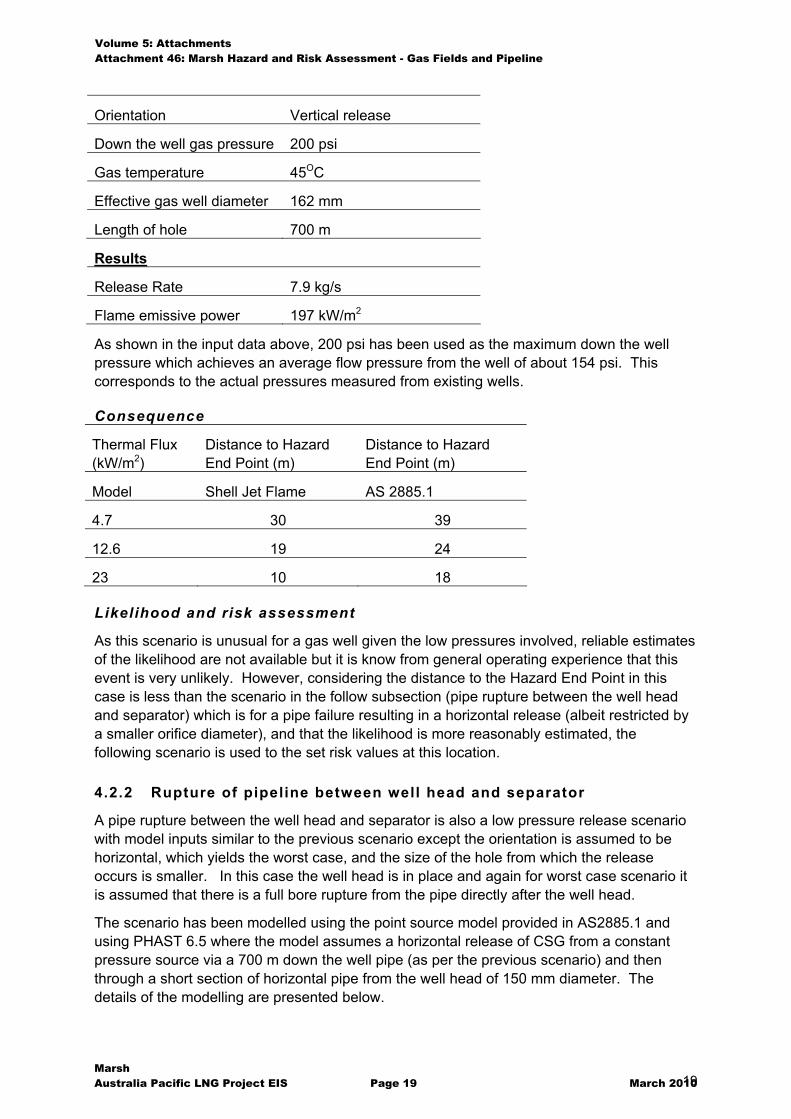
Orientation Vertical release
Down the well gas pressure 200 psi
Gas temperature 45OC
Effective gas well diameter 162 mm
Length of hole 700 m
Results
Release Rate 7.9 kg/s
Flame emissive power 197 kW/m2
As shown in the input data above, 200 psi has been used as the maximum down the well pressure which achieves an average flow pressure from the well of about 154 psi. This corresponds to the actual pressures measured from existing wells.
Consequence
Thermal Flux (kW/m2)
Distance to Hazard End Point (m)
Distance to Hazard End Point (m)
Model Shell Jet Flame AS 2885.1
4.7 30 39
12.6 19 24
23 10 18
Likelihood and risk assessment
As this scenario is unusual for a gas well given the low pressures involved, reliable estimates of the likelihood are not available but it is know from general operating experience that this event is very unlikely. However, considering the distance to the Hazard End Point in this case is less than the scenario in the follow subsection (pipe rupture between the well head and separator) which is for a pipe failure resulting in a horizontal release (albeit restricted by a smaller orifice diameter), and that the likelihood is more reasonably estimated, the following scenario is used to the set risk values at this location.
4.2.2 Rupture of pipeline between well head and separator
A pipe rupture between the well head and separator is also a low pressure release scenario with model inputs similar to the previous scenario except the orientation is assumed to be horizontal, which yields the worst case, and the size of the hole from which the release occurs is smaller. In this case the well head is in place and again for worst case scenario it is assumed that there is a full bore rupture from the pipe directly after the well head.
The scenario has been modelled using the point source model provided in AS2885.1 and using PHAST 6.5 where the model assumes a horizontal release of CSG from a constant pressure source via a 700 m down the well pipe (as per the previous scenario) and then through a short section of horizontal pipe from the well head of 150 mm diameter. The details of the modelling are presented below.
Volume 5: Attachments Attachment 46: Marsh Hazard and Risk Assessment - Gas Fields and Pipeline
Marsh Australia Pacific LNG Project EIS Page 20 March 2010 20
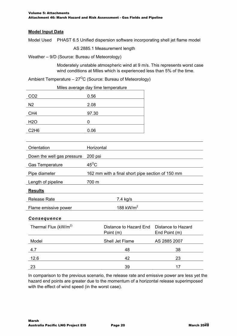
Model Input Data
Model Used PHAST 6.5 Unified dispersion software incorporating shell jet flame model
AS 2885.1 Measurement length
Weather – 9/D (Source: Bureau of Meteorology)
Moderately unstable atmospheric wind at 9 m/s. This represents worst case wind conditions at Miles which is experienced less than 5% of the time.
Ambient Temperature – 27OC (Source: Bureau of Meteorology)
Miles average day time temperature
CO2 0.56
N2 2.08
CH4 97.30
H2O 0
C2H6 0.06
Orientation Horizontal
Down the well gas pressure 200 psi
Gas Temperature 45OC
Pipe diameter 162 mm with a final short pipe section of 150 mm
Length of pipeline 700 m
Results
Release Rate 7.4 kg/s
Flame emissive power 188 kW/m2
Consequence
Thermal Flux (kW/m2) Distance to Hazard End Point (m)
Distance to Hazard End Point (m)
Model Shell Jet Flame AS 2885 2007
4.7 48 38
12.6 42 23
23 39 17
In comparison to the previous scenario, the release rate and emissive power are less yet the hazard end points are greater due to the momentum of a horizontal release superimposed with the effect of wind speed (in the worst case).

Volume 5: Attachments Attachment 46: Marsh Hazard and Risk Assessment - Gas Fields and Pipeline
Marsh Australia Pacific LNG Project EIS Page 21 March 2010 21
Likelihood
The likelihood in this case is taken as that of a pipe section failure which is 1 x 10⁻¹⁰ hr-1 (=0.876 x 10⁻⁶ yr-1) as referenced in Appendix B.
Risk Value
The risk of fatality at 42 m (12.6 k W/m2) due to a pipe rupture at the well head is 0.0876 in a million per year.
The risk of fatality at 39 m (23 kW/m2) due to a pipe rupture at the well head is 0.631 in a million per year.
Both these risks are below the figures listed in HIPAP 4 for residential land use.
4.2.3 Rupture of pipe in gas gathering system
This scenario assumes a full bore rupture of the largest steel pipe in the gathering system prior to the gas processing facilities. Because the pipe is of non rupture design and low pressure, this scenario is considered to be not credible. Nevertheless the scenario has been modelled to show the hazard it represents.
The scenario has been modelled using the point source model provided in AS2885.1 and using PHAST 6.5 where the model assumes a full bore rupture resulting in a vertical release of CSG from a 20 km length of pipe. It is assumed that the failure occurs somewhere in the middle of the line so that the overall discharge is a combination of gas released from both directions, which is the worst case. The details of the modelling are presented below.
Model Input Data
Model Used PHAST 6.5 Unified dispersion software incorporating shell jet flame model
AS 2885.1 Measurement length
Weather – 9/D (Source: Bureau of Meteorology)
Moderately unstable atmospheric wind at 9 m/s. This represents worst case wind conditions at Miles which is experienced less than 5% of the time
Ambient Temperature – 27OC (Source: Bureau of Meteorology)
Miles average day time temperature
CSG Components Mol%
CO2 0.50
N2 2.3
CH4 97.20
H2O 0
C2H6 n/a
Orientation Vertical
Gas Pressure 200 psi
Volume 5: Attachments Attachment 46: Marsh Hazard and Risk Assessment - Gas Fields and Pipeline
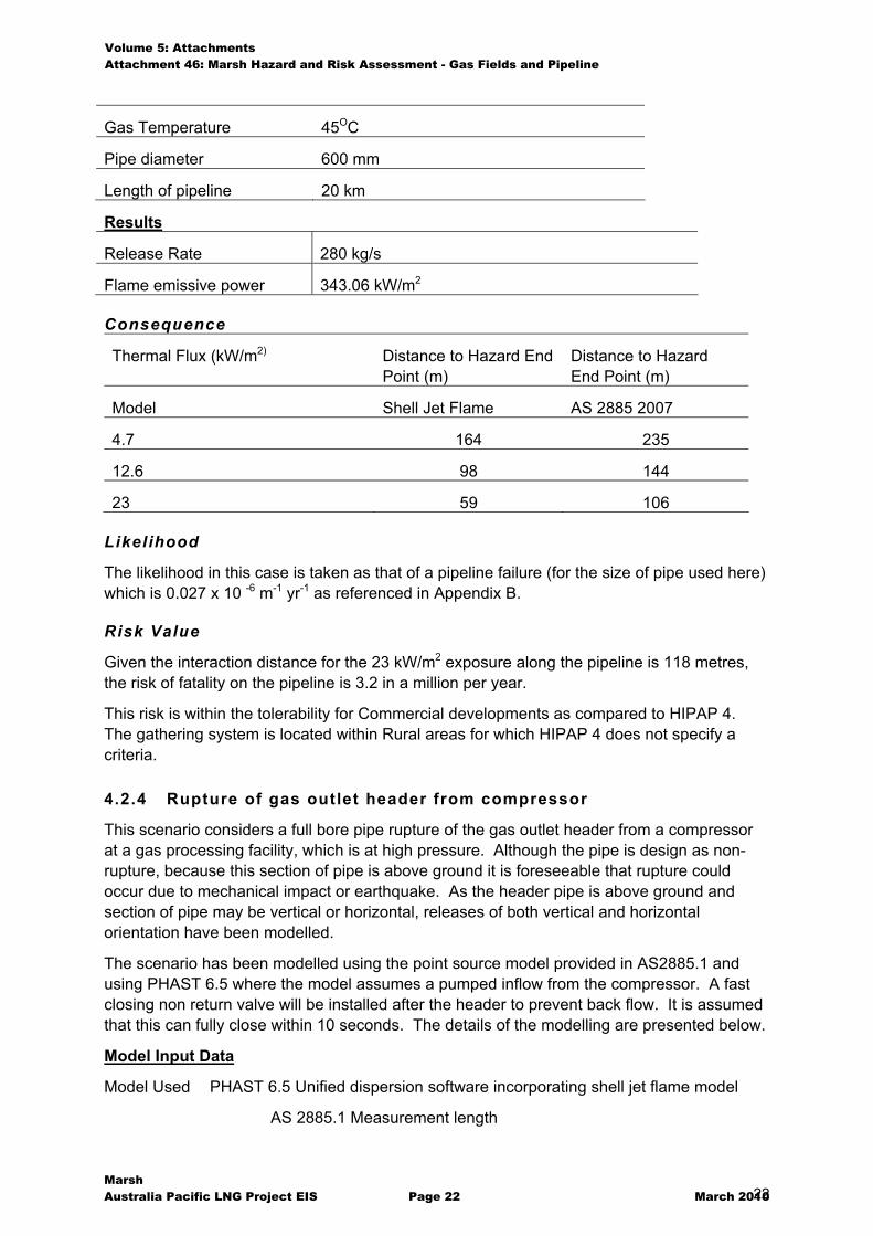
Marsh Australia Pacific LNG Project EIS Page 22 March 2010 22
Gas Temperature 45OC
Pipe diameter 600 mm
Length of pipeline 20 km
Results
Release Rate 280 kg/s
Flame emissive power 343.06 kW/m2
Consequence
Thermal Flux (kW/m2) Distance to Hazard End Point (m)
Distance to Hazard End Point (m)
Model Shell Jet Flame AS 2885 2007
4.7 164 235
12.6 98 144
23 59 106
Likelihood
The likelihood in this case is taken as that of a pipeline failure (for the size of pipe used here) which is 0.027 x 10 -6 m-1 yr-1 as referenced in Appendix B.
Risk Value
Given the interaction distance for the 23 kW/m2 exposure along the pipeline is 118 metres, the risk of fatality on the pipeline is 3.2 in a million per year.
This risk is within the tolerability for Commercial developments as compared to HIPAP 4. The gathering system is located within Rural areas for which HIPAP 4 does not specify a criteria.
4.2.4 Rupture of gas outlet header from compressor
This scenario considers a full bore pipe rupture of the gas outlet header from a compressor at a gas processing facility, which is at high pressure. Although the pipe is design as non-rupture, because this section of pipe is above ground it is foreseeable that rupture could occur due to mechanical impact or earthquake. As the header pipe is above ground and section of pipe may be vertical or horizontal, releases of both vertical and horizontal orientation have been modelled.
The scenario has been modelled using the point source model provided in AS2885.1 and using PHAST 6.5 where the model assumes a pumped inflow from the compressor. A fast closing non return valve will be installed after the header to prevent back flow. It is assumed that this can fully close within 10 seconds. The details of the modelling are presented below.
Model Input Data
Model Used PHAST 6.5 Unified dispersion software incorporating shell jet flame model
AS 2885.1 Measurement length
Volume 5: Attachments Attachment 46: Marsh Hazard and Risk Assessment - Gas Fields and Pipeline
Marsh Australia Pacific LNG Project EIS Page 23 March 2010 23
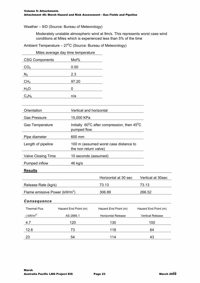
Weather – 9/D (Source: Bureau of Meteorology)
Moderately unstable atmospheric wind at 9m/s. This represents worst case wind conditions at Miles which is experienced less than 5% of the time
Ambient Temperature – 270C (Source: Bureau of Meteorology)
Miles average day time temperature
CSG Components Mol%
CO2 0.50
N2 2.3
CH4 97.20
H2O 0
C2H6 n/a
Orientation Vertical and horizontal
Gas Pressure 15,000 KPa
Gas Temperature Initially 600C after compression, then 450C pumped flow
Pipe diameter 600 mm
Length of pipeline 100 m (assumed worst case distance to the non return valve)
Valve Closing Time 10 seconds (assumed)
Pumped inflow 46 kg/s
Results
Horizontal at 30 sec Vertical at 30sec
Release Rate (kg/s) 73.13 73.13
Flame emissive Power (kW/m2) 306.89 266.52
Consequence
Thermal Flux
( kW/m2)
Hazard End Point (m)
AS 2885.1
Hazard End Point (m)
Horizontal Release
Hazard End Point (m)
Vertical Release
4.7 120 130 100
12.6 73 118 64
23 54 114 43
Volume 5: Attachments Attachment 46: Marsh Hazard and Risk Assessment - Gas Fields and Pipeline
Marsh Australia Pacific LNG Project EIS Page 24 March 2010 24
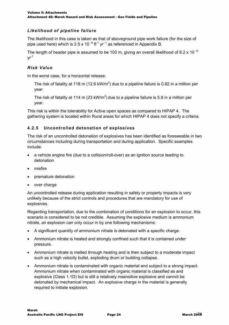
Likelihood of pipeline failure
The likelihood in this case is taken as that of aboveground pipe work failure (for the size of pipe used here) which is 2.5 x 10 -8 ft-1 yr--1 as referenced in Appendix B.
The length of header pipe is assumed to be 100 m, giving an overall likelihood of 8.2 x 10 -6 yr-1
Risk Value
In the worst case, for a horizontal release:
The risk of fatality at 118 m (12.6 kW/m2) due to a pipeline failure is 0.82 in a million per year.
The risk of fatality at 114 m (23 kW/m2) due to a pipeline failure is 5.9 in a million per year.
This risk is within the tolerability for Active open spaces as compared to HIPAP 4. The gathering system is located within Rural areas for which HIPAP 4 does not specify a criteria.
4.2.5 Uncontrolled detonation of explosives
The risk of an uncontrolled detonation of explosives has been identified as foreseeable in two circumstances including during transportation and during application. Specific examples include:
� a vehicle engine fire (due to a collision/roll-over) as an ignition source leading to detonation
� misfire
� premature detonation
� over charge
An uncontrolled release during application resulting in safety or property impacts is very unlikely because of the strict controls and procedures that are mandatory for use of explosives.
Regarding transportation, due to the combination of conditions for an explosion to occur, this scenario is considered to be not credible. Assuming the explosive medium is ammonium nitrate, an explosion can only occur in by one following mechanisms:
� A significant quantity of ammonium nitrate is detonated with a specific charge.
� Ammonium nitrate is heated and strongly confined such that it is contained under pressure.
� Ammonium nitrate is melted through heating and is then subject to a moderate impact such as a high velocity bullet, exploding drum or building collapse.
� Ammonium nitrate is contaminated with organic material and subject to a strong impact. Ammonium nitrate when contaminated with organic material is classified as and explosive (Class 1.1D) but is still a relatively insensitive explosive and cannot be detonated by mechanical impact. An explosive charge in the material is generally required to initiate explosion.
Volume 5: Attachments Attachment 46: Marsh Hazard and Risk Assessment - Gas Fields and Pipeline
Marsh Australia Pacific LNG Project EIS Page 25 March 2010 25
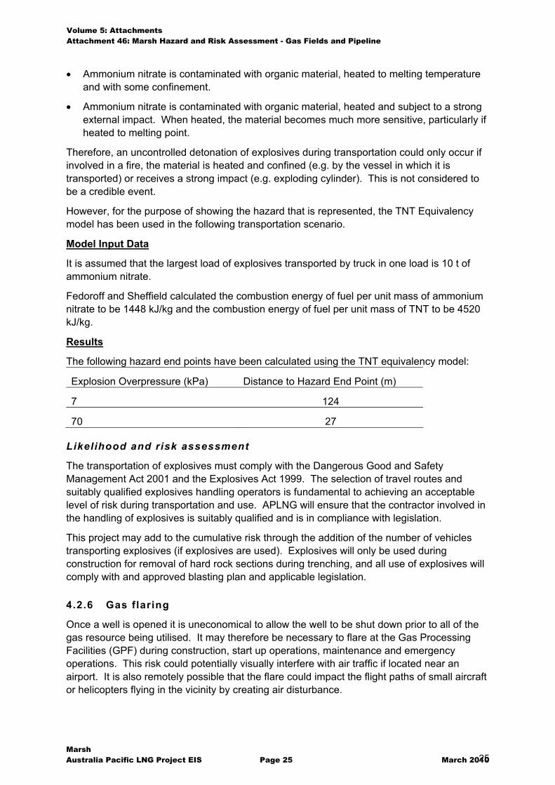
� Ammonium nitrate is contaminated with organic material, heated to melting temperature and with some confinement.
� Ammonium nitrate is contaminated with organic material, heated and subject to a strong external impact. When heated, the material becomes much more sensitive, particularly if heated to melting point.
Therefore, an uncontrolled detonation of explosives during transportation could only occur if involved in a fire, the material is heated and confined (e.g. by the vessel in which it is transported) or receives a strong impact (e.g. exploding cylinder). This is not considered to be a credible event.
However, for the purpose of showing the hazard that is represented, the TNT Equivalency model has been used in the following transportation scenario.
Model Input Data
It is assumed that the largest load of explosives transported by truck in one load is 10 t of ammonium nitrate.
Fedoroff and Sheffield calculated the combustion energy of fuel per unit mass of ammonium nitrate to be 1448 kJ/kg and the combustion energy of fuel per unit mass of TNT to be 4520 kJ/kg.
Results
The following hazard end points have been calculated using the TNT equivalency model:
Explosion Overpressure (kPa) Distance to Hazard End Point (m)
7 124
70 27
Likelihood and risk assessment
The transportation of explosives must comply with the Dangerous Good and Safety Management Act 2001 and the Explosives Act 1999. The selection of travel routes and suitably qualified explosives handling operators is fundamental to achieving an acceptable level of risk during transportation and use. APLNG will ensure that the contractor involved in the handling of explosives is suitably qualified and is in compliance with legislation.
This project may add to the cumulative risk through the addition of the number of vehicles transporting explosives (if explosives are used). Explosives will only be used during construction for removal of hard rock sections during trenching, and all use of explosives will comply with and approved blasting plan and applicable legislation.
4.2.6 Gas flaring
Once a well is opened it is uneconomical to allow the well to be shut down prior to all of the gas resource being utilised. It may therefore be necessary to flare at the Gas Processing Facilities (GPF) during construction, start up operations, maintenance and emergency operations. This risk could potentially visually interfere with air traffic if located near an airport. It is also remotely possible that the flare could impact the flight paths of small aircraft or helicopters flying in the vicinity by creating air disturbance.
Volume 5: Attachments Attachment 46: Marsh Hazard and Risk Assessment - Gas Fields and Pipeline
Marsh Australia Pacific LNG Project EIS Page 26 March 2010 26
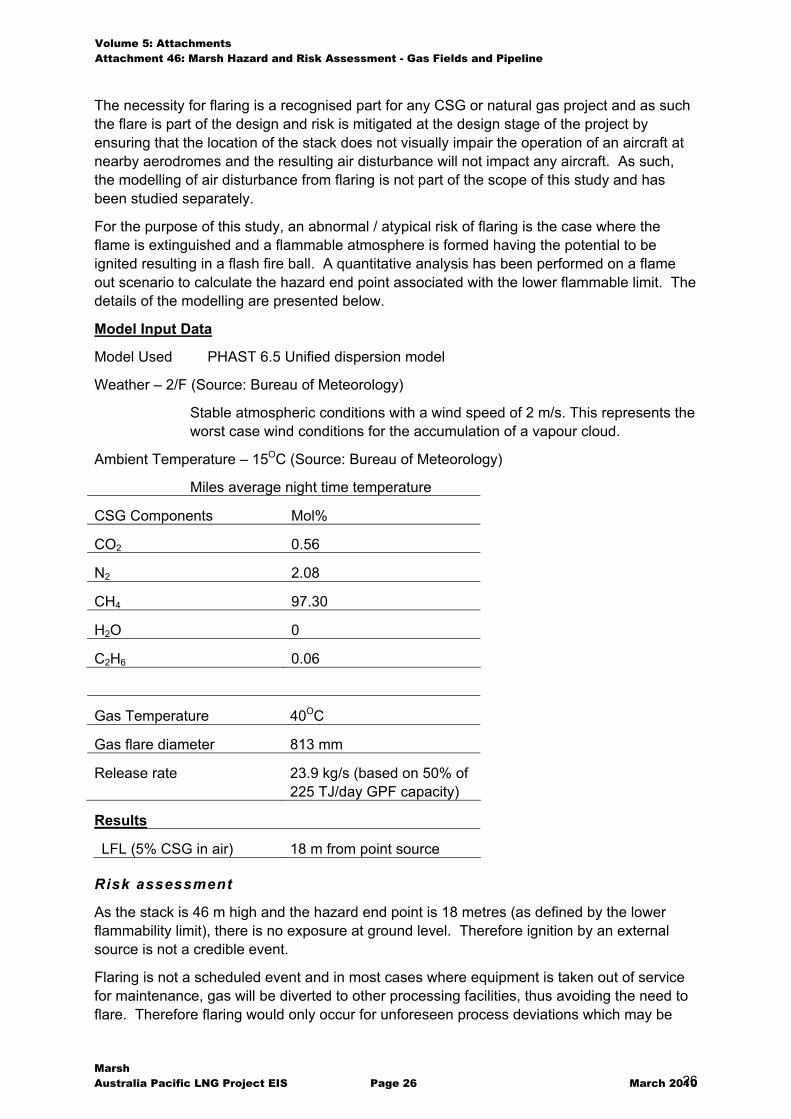
The necessity for flaring is a recognised part for any CSG or natural gas project and as such the flare is part of the design and risk is mitigated at the design stage of the project by ensuring that the location of the stack does not visually impair the operation of an aircraft at nearby aerodromes and the resulting air disturbance will not impact any aircraft. As such, the modelling of air disturbance from flaring is not part of the scope of this study and has been studied separately.
For the purpose of this study, an abnormal / atypical risk of flaring is the case where the flame is extinguished and a flammable atmosphere is formed having the potential to be ignited resulting in a flash fire ball. A quantitative analysis has been performed on a flame out scenario to calculate the hazard end point associated with the lower flammable limit. The details of the modelling are presented below.
Model Input Data
Model Used PHAST 6.5 Unified dispersion model
Weather – 2/F (Source: Bureau of Meteorology)
Stable atmospheric conditions with a wind speed of 2 m/s. This represents the worst case wind conditions for the accumulation of a vapour cloud.
Ambient Temperature – 15OC (Source: Bureau of Meteorology)
Miles average night time temperature
CSG Components Mol%
CO2 0.56
N2 2.08
CH4 97.30
H2O 0
C2H6 0.06
Gas Temperature 40OC
Gas flare diameter 813 mm
Release rate 23.9 kg/s (based on 50% of 225 TJ/day GPF capacity)
Results
LFL (5% CSG in air) 18 m from point source
Risk assessment
As the stack is 46 m high and the hazard end point is 18 metres (as defined by the lower flammability limit), there is no exposure at ground level. Therefore ignition by an external source is not a credible event.
Flaring is not a scheduled event and in most cases where equipment is taken out of service for maintenance, gas will be diverted to other processing facilities, thus avoiding the need to flare. Therefore flaring would only occur for unforeseen process deviations which may be
Volume 5: Attachments Attachment 46: Marsh Hazard and Risk Assessment - Gas Fields and Pipeline
Marsh Australia Pacific LNG Project EIS Page 27 March 2010 27
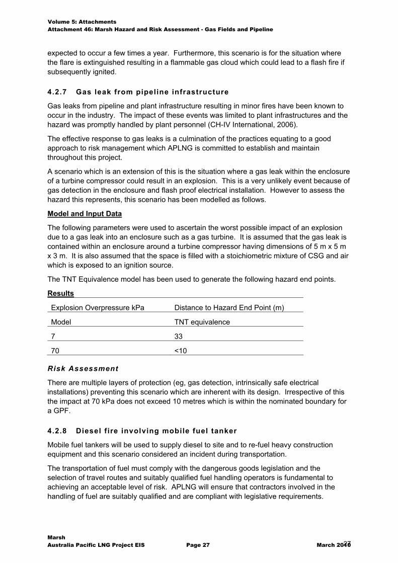
expected to occur a few times a year. Furthermore, this scenario is for the situation where the flare is extinguished resulting in a flammable gas cloud which could lead to a flash fire if subsequently ignited.
4.2.7 Gas leak from pipeline infrastructure
Gas leaks from pipeline and plant infrastructure resulting in minor fires have been known to occur in the industry. The impact of these events was limited to plant infrastructures and the hazard was promptly handled by plant personnel (CH-IV International, 2006).
The effective response to gas leaks is a culmination of the practices equating to a good approach to risk management which APLNG is committed to establish and maintain throughout this project.
A scenario which is an extension of this is the situation where a gas leak within the enclosure of a turbine compressor could result in an explosion. This is a very unlikely event because of gas detection in the enclosure and flash proof electrical installation. However to assess the hazard this represents, this scenario has been modelled as follows.
Model and Input Data
The following parameters were used to ascertain the worst possible impact of an explosion due to a gas leak into an enclosure such as a gas turbine. It is assumed that the gas leak is contained within an enclosure around a turbine compressor having dimensions of 5 m x 5 m x 3 m. It is also assumed that the space is filled with a stoichiometric mixture of CSG and air which is exposed to an ignition source.
The TNT Equivalence model has been used to generate the following hazard end points.
Results
Explosion Overpressure kPa Distance to Hazard End Point (m)
Model TNT equivalence
7 33
70 <10
Risk Assessment
There are multiple layers of protection (eg, gas detection, intrinsically safe electrical installations) preventing this scenario which are inherent with its design. Irrespective of this the impact at 70 kPa does not exceed 10 metres which is within the nominated boundary for a GPF.
4.2.8 Diesel f ire involving mobile fuel tanker
Mobile fuel tankers will be used to supply diesel to site and to re-fuel heavy construction equipment and this scenario considered an incident during transportation.
The transportation of fuel must comply with the dangerous goods legislation and the selection of travel routes and suitably qualified fuel handling operators is fundamental to achieving an acceptable level of risk. APLNG will ensure that contractors involved in the handling of fuel are suitably qualified and are compliant with legislative requirements.
Volume 5: Attachments Attachment 46: Marsh Hazard and Risk Assessment - Gas Fields and Pipeline
Marsh Australia Pacific LNG Project EIS Page 28 March 2010 28
4.2.9 Pipeline gas explosion
During decommissioning it is foreseeable that sections of the pipeline may not be correctly purged and hot work introduced. In the event that the pipeline is filled with a mixture of gas and air within the flammability limits an overpressure explosion could occur.
Volume 5: Attachments Attachment 46: Marsh Hazard and Risk Assessment - Gas Fields and Pipeline
Marsh Australia Pacific LNG Project EIS Page 29 March 2010 29
5
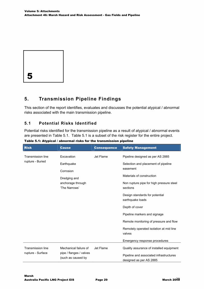
5. Transmission Pipeline Findings
This section of the report identifies, evaluates and discusses the potential atypical / abnormal risks associated with the main transmission pipeline.
5.1 Potential Risks Identified
Potential risks identified for the transmission pipeline as a result of atypical / abnormal events are presented in Table 5.1. Table 5.1 is a subset of the risk register for the entire project. Table 5.1: Atypical / abnormal risks for the transmission pipeline
Risk Cause Consequence Safety Management
Transmission line rupture - Buried
Excavation
Earthquake
Corrosion
Dredging and anchorage through ‘The Narrows’
Jet Flame Pipeline designed as per AS 2885
Selection and placement of pipeline easement
Materials of construction
Non rupture pipe for high pressure steel sections
Design standards for potential earthquake loads
Depth of cover
Pipeline markers and signage
Remote monitoring of pressure and flow
Remotely operated isolation at mid line valves
Emergency response procedures
Transmission line rupture - Surface
Mechanical failure of pipe / flanges / valves (such as caused by
Jet Flame Quality assurance of installed equipment
Pipeline and associated infrastructures designed as per AS 2885
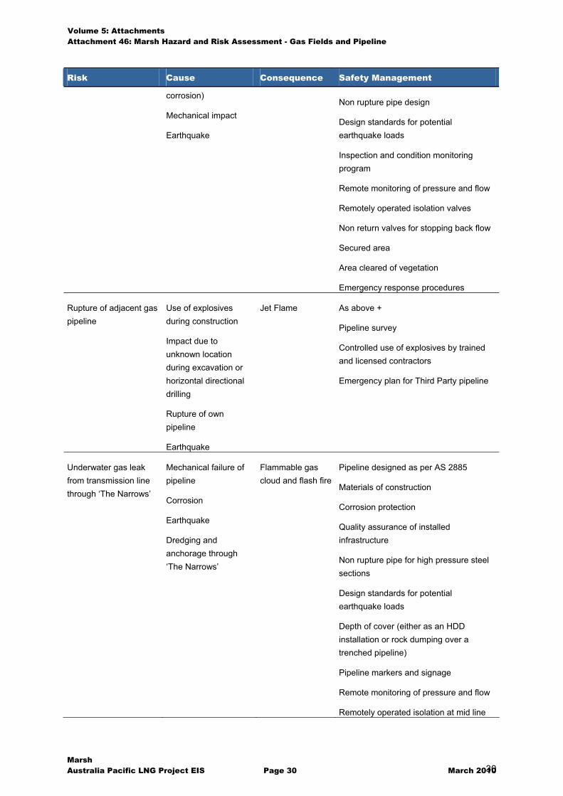
Volume 5: Attachments Attachment 46: Marsh Hazard and Risk Assessment - Gas Fields and Pipeline
Marsh Australia Pacific LNG Project EIS Page 30 March 2010 30
Risk Cause Consequence Safety Management
corrosion)
Mechanical impact
Earthquake
Non rupture pipe design
Design standards for potential earthquake loads
Inspection and condition monitoring program
Remote monitoring of pressure and flow
Remotely operated isolation valves
Non return valves for stopping back flow
Secured area
Area cleared of vegetation
Emergency response procedures
Rupture of adjacent gas pipeline
Use of explosives during construction
Impact due to unknown location during excavation or horizontal directional drilling
Rupture of own pipeline
Earthquake
Jet Flame As above +
Pipeline survey
Controlled use of explosives by trained and licensed contractors
Emergency plan for Third Party pipeline
Underwater gas leak from transmission line through ‘The Narrows’
Mechanical failure of pipeline
Corrosion
Earthquake
Dredging and anchorage through ‘The Narrows’
Flammable gas cloud and flash fire
Pipeline designed as per AS 2885
Materials of construction
Corrosion protection
Quality assurance of installed infrastructure
Non rupture pipe for high pressure steel sections
Design standards for potential earthquake loads
Depth of cover (either as an HDD installation or rock dumping over a trenched pipeline)
Pipeline markers and signage
Remote monitoring of pressure and flow
Remotely operated isolation at mid line
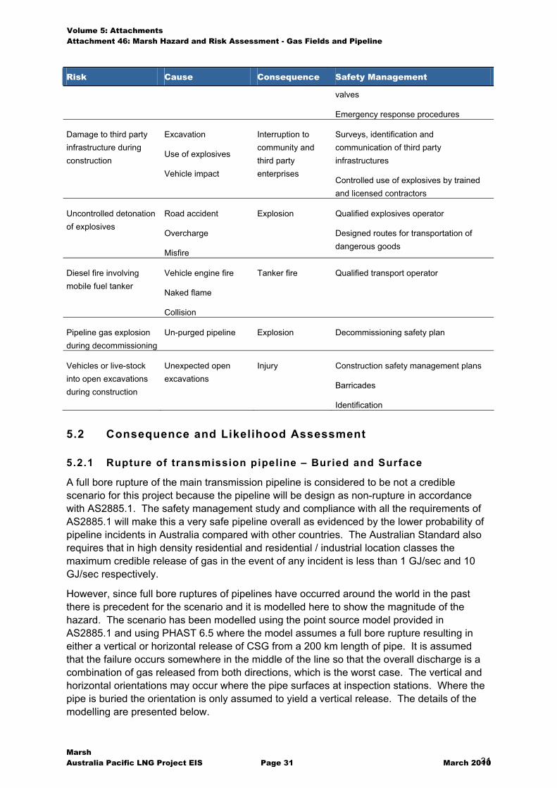
Volume 5: Attachments Attachment 46: Marsh Hazard and Risk Assessment - Gas Fields and Pipeline
Marsh Australia Pacific LNG Project EIS Page 31 March 2010 31
Risk Cause Consequence Safety Management
valves
Emergency response procedures
Damage to third party infrastructure during construction
Excavation
Use of explosives
Vehicle impact
Interruption to community and third party enterprises
Surveys, identification and communication of third party infrastructures
Controlled use of explosives by trained and licensed contractors
Uncontrolled detonation of explosives
Road accident
Overcharge
Misfire
Explosion Qualified explosives operator
Designed routes for transportation of dangerous goods
Diesel fire involving mobile fuel tanker
Vehicle engine fire
Naked flame
Collision
Tanker fire Qualified transport operator
Pipeline gas explosion during decommissioning
Un-purged pipeline Explosion Decommissioning safety plan
Vehicles or live-stock into open excavations during construction
Unexpected open excavations
Injury Construction safety management plans
Barricades
Identification
5.2 Consequence and Likelihood Assessment
5.2.1 Rupture of transmission pipeline – Buried and Surface
A full bore rupture of the main transmission pipeline is considered to be not a credible scenario for this project because the pipeline will be design as non-rupture in accordance with AS2885.1. The safety management study and compliance with all the requirements of AS2885.1 will make this a very safe pipeline overall as evidenced by the lower probability of pipeline incidents in Australia compared with other countries. The Australian Standard also requires that in high density residential and residential / industrial location classes the maximum credible release of gas in the event of any incident is less than 1 GJ/sec and 10 GJ/sec respectively.
However, since full bore ruptures of pipelines have occurred around the world in the past there is precedent for the scenario and it is modelled here to show the magnitude of the hazard. The scenario has been modelled using the point source model provided in AS2885.1 and using PHAST 6.5 where the model assumes a full bore rupture resulting in either a vertical or horizontal release of CSG from a 200 km length of pipe. It is assumed that the failure occurs somewhere in the middle of the line so that the overall discharge is a combination of gas released from both directions, which is the worst case. The vertical and horizontal orientations may occur where the pipe surfaces at inspection stations. Where the pipe is buried the orientation is only assumed to yield a vertical release. The details of the modelling are presented below.
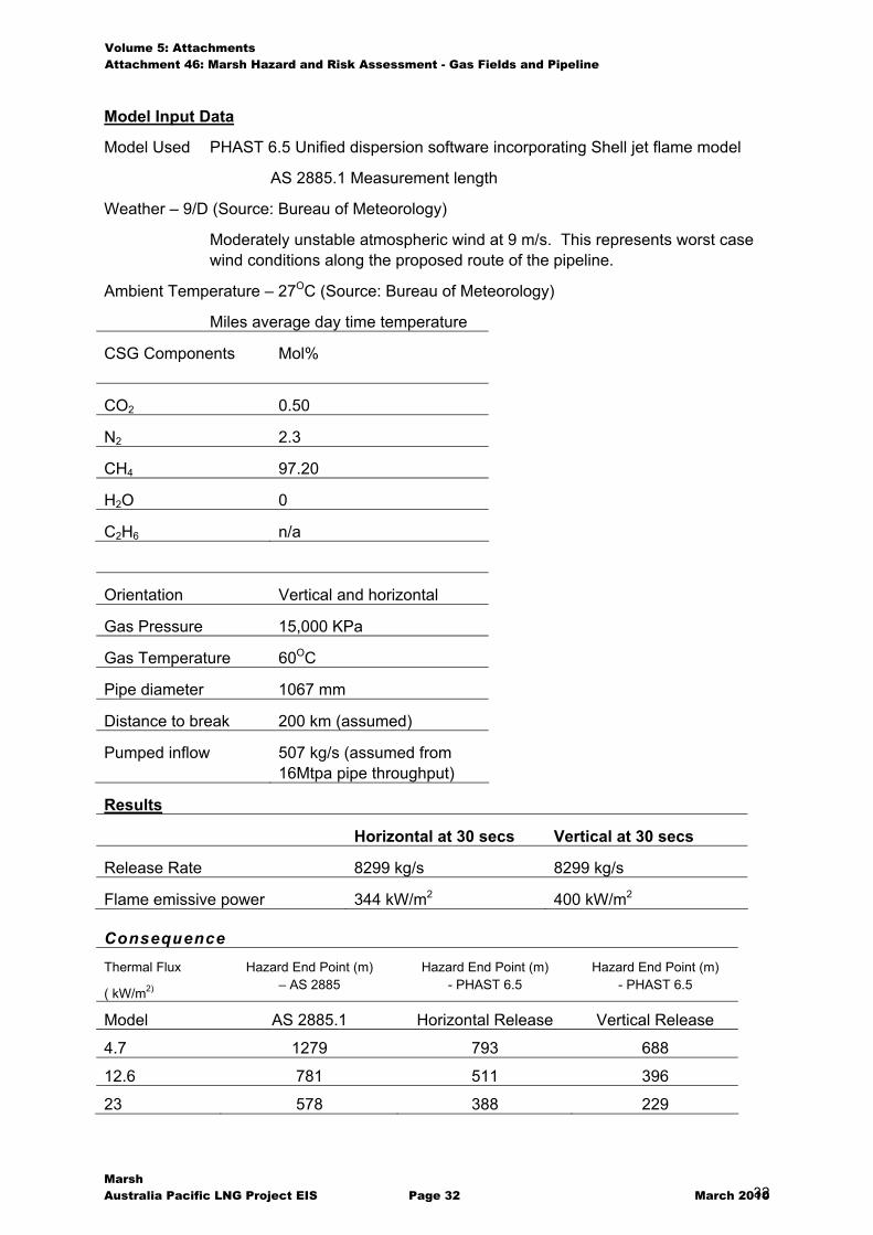
Volume 5: Attachments Attachment 46: Marsh Hazard and Risk Assessment - Gas Fields and Pipeline
Marsh Australia Pacific LNG Project EIS Page 32 March 2010 32
Model Input Data
Model Used PHAST 6.5 Unified dispersion software incorporating Shell jet flame model
AS 2885.1 Measurement length
Weather – 9/D (Source: Bureau of Meteorology)
Moderately unstable atmospheric wind at 9 m/s. This represents worst case wind conditions along the proposed route of the pipeline.
Ambient Temperature – 27OC (Source: Bureau of Meteorology)
Miles average day time temperature
CSG Components
Mol%
CO2 0.50
N2 2.3
CH4 97.20
H2O 0
C2H6 n/a
Orientation Vertical and horizontal
Gas Pressure 15,000 KPa
Gas Temperature 60OC
Pipe diameter 1067 mm
Distance to break 200 km (assumed)
Pumped inflow 507 kg/s (assumed from 16Mtpa pipe throughput)
Results
Horizontal at 30 secs Vertical at 30 secs
Release Rate 8299 kg/s 8299 kg/s
Flame emissive power 344 kW/m2 400 kW/m2
Consequence
Thermal Flux
( kW/m2)
Hazard End Point (m) – AS 2885
Hazard End Point (m) - PHAST 6.5
Hazard End Point (m) - PHAST 6.5
Model AS 2885.1 Horizontal Release Vertical Release
4.7 1279 793 688
12.6 781 511 396
23 578 388 229
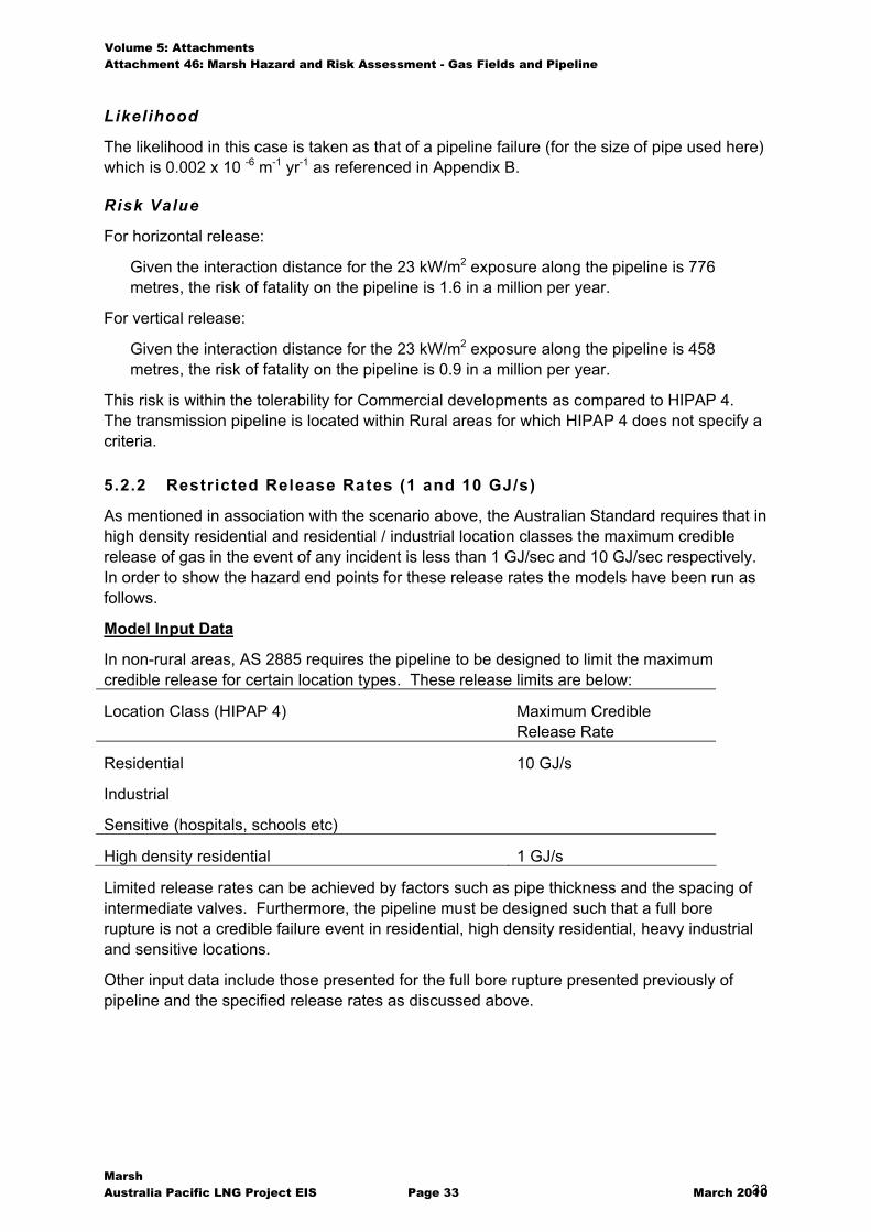
Volume 5: Attachments Attachment 46: Marsh Hazard and Risk Assessment - Gas Fields and Pipeline
Marsh Australia Pacific LNG Project EIS Page 33 March 2010 33
Likelihood
The likelihood in this case is taken as that of a pipeline failure (for the size of pipe used here) which is 0.002 x 10 -6 m-1 yr-1 as referenced in Appendix B.
Risk Value
For horizontal release:
Given the interaction distance for the 23 kW/m2 exposure along the pipeline is 776 metres, the risk of fatality on the pipeline is 1.6 in a million per year.
For vertical release:
Given the interaction distance for the 23 kW/m2 exposure along the pipeline is 458 metres, the risk of fatality on the pipeline is 0.9 in a million per year.
This risk is within the tolerability for Commercial developments as compared to HIPAP 4. The transmission pipeline is located within Rural areas for which HIPAP 4 does not specify a criteria.
5.2.2 Restricted Release Rates (1 and 10 GJ/s)
As mentioned in association with the scenario above, the Australian Standard requires that in high density residential and residential / industrial location classes the maximum credible release of gas in the event of any incident is less than 1 GJ/sec and 10 GJ/sec respectively. In order to show the hazard end points for these release rates the models have been run as follows.
Model Input Data
In non-rural areas, AS 2885 requires the pipeline to be designed to limit the maximum credible release for certain location types. These release limits are below:
Location Class (HIPAP 4) Maximum Credible Release Rate
Residential
Industrial
Sensitive (hospitals, schools etc)
10 GJ/s
High density residential 1 GJ/s
Limited release rates can be achieved by factors such as pipe thickness and the spacing of intermediate valves. Furthermore, the pipeline must be designed such that a full bore rupture is not a credible failure event in residential, high density residential, heavy industrial and sensitive locations.
Other input data include those presented for the full bore rupture presented previously of pipeline and the specified release rates as discussed above.
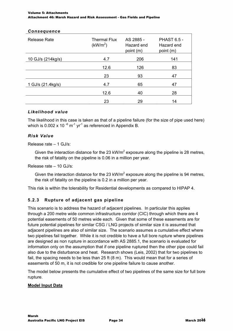
Volume 5: Attachments Attachment 46: Marsh Hazard and Risk Assessment - Gas Fields and Pipeline
Marsh Australia Pacific LNG Project EIS Page 34 March 2010 34
Consequence
Release Rate Thermal Flux (kW/m2)
AS 2885 -Hazard end point (m)
PHAST 6.5 - Hazard end point (m)
10 GJ/s (214kg/s) 4.7 206 141
12.6 126 83
23 93 47
1 GJ/s (21.4kg/s) 4.7 65 47
12.6 40 28
23 29 14
Likelihood value
The likelihood in this case is taken as that of a pipeline failure (for the size of pipe used here) which is 0.002 x 10 -6 m-1 yr-1 as referenced in Appendix B.
Risk Value
Release rate – 1 GJ/s:
Given the interaction distance for the 23 kW/m2 exposure along the pipeline is 28 metres, the risk of fatality on the pipeline is 0.06 in a million per year.
Release rate – 10 GJ/s:
Given the interaction distance for the 23 kW/m2 exposure along the pipeline is 94 metres, the risk of fatality on the pipeline is 0.2 in a million per year.
This risk is within the tolerability for Residential developments as compared to HIPAP 4.
5.2.3 Rupture of adjacent gas pipeline
This scenario is to address the hazard of adjacent pipelines. In particular this applies through a 200 metre wide common infrastructure corridor (CIC) through which there are 4 potential easements of 50 metres wide each. Given that some of these easements are for future potential pipelines for similar CSG / LNG projects of similar size it is assumed that adjacent pipelines are also of similar size. The scenario assumes a cumulative effect where two pipelines fail together. While it is not credible to have a full bore rupture where pipelines are designed as non rupture in accordance with AS 2885.1, the scenario is evaluated for information only on the assumption that if one pipeline ruptured then the other pipe could fail also due to the disturbance and heat. Research shows (Leis, 2002) that for two pipelines to fail, the spacing needs to be less than 25 ft (8 m). This would mean that for a series of easements of 50 m, it is not credible for one pipeline failure to cause another.
The model below presents the cumulative effect of two pipelines of the same size for full bore rupture.
Model Input Data
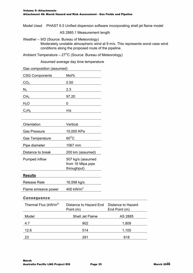
Volume 5: Attachments Attachment 46: Marsh Hazard and Risk Assessment - Gas Fields and Pipeline
Marsh Australia Pacific LNG Project EIS Page 35 March 2010 35
Model Used PHAST 6.5 Unified dispersion software incorporating shell jet flame model
AS 2885.1 Measurement length
Weather – 9/D (Source: Bureau of Meteorology) Moderately unstable atmospheric wind at 9 m/s. This represents worst case wind conditions along the proposed route of the pipeline.
Ambient Temperature – 27OC (Source: Bureau of Meteorology)
Assumed average day time temperature
Gas composition (assumed)
CSG Components Mol%
CO2 0.50
N2 2.3
CH4 97.20
H2O 0
C2H6 n/a
Orientation Vertical
Gas Pressure 15,000 KPa
Gas Temperature 60OC
Pipe diameter 1067 mm
Distance to break 200 km (assumed)
Pumped inflow 507 kg/s (assumed from 16 Mtpa pipe throughput)
Results
Release Rate 16,598 kg/s
Flame emissive power 400 kW/m2
Consequence
Thermal Flux (kW/m2) Distance to Hazard End Point (m)
Distance to Hazard End Point (m)
Model Shell Jet Flame AS 2885
4.7 902 1,809
12.6 514 1,105
23 291 818
Volume 5: Attachments Attachment 46: Marsh Hazard and Risk Assessment - Gas Fields and Pipeline
Marsh Australia Pacific LNG Project EIS Page 36 March 2010 36
Likelihood Value
The likelihood in this case is the same as a single pipeline because it is assumed that the failure of one causes the failure of the other, which is 0.002 x 10 -6 m-1 yr-1 as referenced in Appendix B.
Risk Value
Given the interaction distance for the 23 kW/m2 exposure along the pipeline is 582 metres, the risk of fatality on the pipeline is 1.2 in a million per year.
This risk is within the tolerability for Commercial developments as compared to HIPAP 4. The transmission pipeline is located within Rural areas for which HIPAP 4 does not specify a criteria.
5.2.4 Damage to third party infrastructures
Significant third party infrastructures that need to coexist with the pipeline include:
� Roadways, in particular national highways
� Railway infrastructure
� Electrical power lines
� Data carrying services
� Other pipelines (eg, water, tailings)
An impact on any of these infrastructures during construction is not likely to be catastrophic because the method of construction does not introduce the hazard intensity for catastrophic losses of other infrastructures to be credible except for potential excavation of data cables or other non-hazardous pipelines. In these cases, the impact is considered to be no more than a number of days at the most. The worst case impact on other infrastructures is due to the fail of a pipeline during operations where the hazard intensity is much greater and the potential effect is as shown by the hazard end point calculations for a full bore pipeline rupture.
The principal controls to avoid these impacts are selection of the pipeline route, methods of construction and safe pipeline design as per AS 2885.1.
5.2.5 Uncontrolled detonation of explosives
The risk of an uncontrolled detonation of explosives has been identified as foreseeable in two circumstances including during transportation and during application. Specific examples include:
� a vehicle engine fire (due to a collision/roll-over) as an ignition source leading to detonation
� misfire
� premature detonation
� over charge
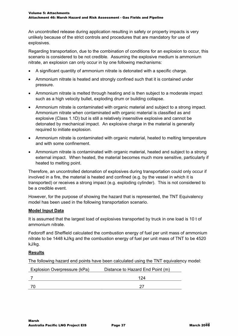
Volume 5: Attachments Attachment 46: Marsh Hazard and Risk Assessment - Gas Fields and Pipeline
Marsh Australia Pacific LNG Project EIS Page 37 March 2010 37
An uncontrolled release during application resulting in safety or property impacts is very unlikely because of the strict controls and procedures that are mandatory for use of explosives.
Regarding transportation, due to the combination of conditions for an explosion to occur, this scenario is considered to be not credible. Assuming the explosive medium is ammonium nitrate, an explosion can only occur in by one following mechanisms:
� A significant quantity of ammonium nitrate is detonated with a specific charge.
� Ammonium nitrate is heated and strongly confined such that it is contained under pressure.
� Ammonium nitrate is melted through heating and is then subject to a moderate impact such as a high velocity bullet, exploding drum or building collapse.
� Ammonium nitrate is contaminated with organic material and subject to a strong impact. Ammonium nitrate when contaminated with organic material is classified as and explosive (Class 1.1D) but is still a relatively insensitive explosive and cannot be detonated by mechanical impact. An explosive charge in the material is generally required to initiate explosion.
� Ammonium nitrate is contaminated with organic material, heated to melting temperature and with some confinement.
� Ammonium nitrate is contaminated with organic material, heated and subject to a strong external impact. When heated, the material becomes much more sensitive, particularly if heated to melting point.
Therefore, an uncontrolled detonation of explosives during transportation could only occur if involved in a fire, the material is heated and confined (e.g. by the vessel in which it is transported) or receives a strong impact (e.g. exploding cylinder). This is not considered to be a credible event.
However, for the purpose of showing the hazard that is represented, the TNT Equivalency model has been used in the following transportation scenario.
Model Input Data
It is assumed that the largest load of explosives transported by truck in one load is 10 t of ammonium nitrate.
Fedoroff and Sheffield calculated the combustion energy of fuel per unit mass of ammonium nitrate to be 1448 kJ/kg and the combustion energy of fuel per unit mass of TNT to be 4520 kJ/kg.
Results
The following hazard end points have been calculated using the TNT equivalency model:
Explosion Overpressure (kPa) Distance to Hazard End Point (m)
7 124
70 27
Volume 5: Attachments Attachment 46: Marsh Hazard and Risk Assessment - Gas Fields and Pipeline
Marsh Australia Pacific LNG Project EIS Page 38 March 2010 38
Likelihood and risk assessment
The transportation of explosives must comply with the Dangerous Good and Safety Management Act 2001 and the Explosives Act 1999. The selection of travel routes and suitably qualified explosives handling operators is fundamental to achieving an acceptable level of risk during transportation and use. APLNG will ensure that the contractor involved in the handling of explosives is suitably qualified and is in compliance with legislation.
This project may add to the cumulative risk through the addition of the number of vehicles transporting explosives (if explosives are used). Explosives will not be used as a matter of course and the use will ultimately be dependent upon the presence of hard rock for sections where trenching is required.
5.2.6 Accommodation fire
During the construction of the pipeline temporary camps will be set up for construction crews. These camps will comprise a kitchen and accommodation units. At the camp sites there will also be a lay-down area for pipeline supplies and diesel fuel storage for refuelling light vehicles. The camps will be periodically moved as the pipeline progresses. While a fire in the temporary pipeline construction camp is possible, it is not expected to result in any off-site impacts. Life safety considerations for camp occupants will be provided in accordance with building code requirements.
5.2.7 Diesel f ire involving mobile fuel tanker
Mobile fuel tankers will be used to supply diesel to site and to re-fuel heavy construction equipment and this scenario considered an incident during transportation.
The transportation of fuel must comply with the dangerous goods legislation and the selection of travel routes and suitably qualified fuel handling operators is fundamental to achieving an acceptable level of risk. APLNG will ensure that contractors involved in the handling of fuel are suitably qualified and are compliant with legislative requirements.
5.2.8 Pipeline gas explosion
During decommissioning it is foreseeable that sections of the pipeline may not be correctly purged and hot work introduced. In the event that the pipeline is filled with a mixture of gas and air within the flammability limits an overpressure explosion could occur.
5.2.9 Rupture of Transmission Pipeline through ‘The Narrows’
Through ‘The Narrows’ on approach to Curtis Island there is the potential for up to four gas pipelines to be installed in a common user corridor. It is planned that the APLNG pipeline will be installed by horizontal direction drilling in this section under the sea floor. In this case it is consider that the risk of failure is significantly less than other sections of the pipeline due to the depth of cover.
However, it may eventuate that the method of construction is not possible for various technical reasons. This will necessitate the pipeline being installed by trenching in the seafloor where potential external interferences such as dredging and anchoring exist. In this case, the result of a rupture under water is the formation of a flammable gas cloud on the surface.
Volume 5: Attachments Attachment 46: Marsh Hazard and Risk Assessment - Gas Fields and Pipeline
Marsh Australia Pacific LNG Project EIS Page 39 March 2010 39
Studies performed by the Petroleum Safety Authority in Norway on large scale releases of gas underwater showed that predictions of the size of cloud formed above the surface using various models available was significantly variant; where predictions of dispersion of gas above the surface could vary from 180 to 400 metres.
5.2.10 Road Trenches not backfil led
The construction of the pipeline requires trenching in areas which could foreseeably be accessed by the public. This may result in injury or fatality from a vehicle incident.
APLNG will ensure that appropriate control of this risk is implemented through a construction safety management plan.
Volume 5: Attachments Attachment 46: Marsh Hazard and Risk Assessment - Gas Fields and Pipeline
Marsh Australia Pacific LNG Project EIS Page 40 March 2010 40
6
6. Appendices A. APLNG’s Approach to Risk Management B. Quantitative Risk Assessment Models C. Unified Dispersion Model D. Shell Jet Flame Model References
Volume 5: Attachments Attachment 46: Marsh Hazard and Risk Assessment - Gas Fields and Pipeline
Marsh Australia Pacific LNG Project EIS Page 41 March 2010 41
Appendix A
APLNG’s Approach to Risk Management Risk Management for the CSG project will be achieved using the following approach:
� Safety Management;
� Engineering and design; and
� Training and awareness of personnel.
Safety Management
The basis for the design and construction of the gas transmission system will be Australian Standard, AS 2885.1 (2007): Pipelines – Gas and Liquid Petroleum, Part 1: Design and Construction, which covers the pipeline itself and associated equipment, such as compression and metering stations. The purpose of this standard is to “ensure the protection of the general public, pipeline operating personnel and the environment, and to ensure safe operation of pipelines that carry petroleum fluids at high pressure”. The fundamentals on which this series of standards are based are:
E. The Standards exist to ensure the safety of the community, protection of the environment and security of supply.
F. A pipeline is to be designed and constructed to have sufficient strength, ductility and toughness to withstand all planned and accidental loads to which it may be subjected during construction, testing and operation.
G. Before a pipeline is placed into operation it has to be inspected and tested to prove its integrity.
H. Important matters relating to safety, engineering design, materials, testing and inspection have to be reviewed and approved by a responsible entity. The responsible entity has to be the pipeline Licensee or its delegate. In each case, the responsible entity has to be defined.
I. Before a pipeline is abandoned, an abandonment plan has to be developed. J. The integrity and safe operation of the pipeline has to be maintained in accordance
with an approved safety and operating plan. K. Where changes occur in or to a pipeline, which alter the design assumptions or affect
the original integrity, appropriate steps have to be taken to assess the changes and to ensure continued safe operation of the pipeline.
The lifetime pipeline safety management process is summarised in Figure 7.1. As this figure depicts, the safety process is ongoing over the life of the pipeline and involves the need to obtain regulatory approvals at key milestones. This hazard and risk study is just one
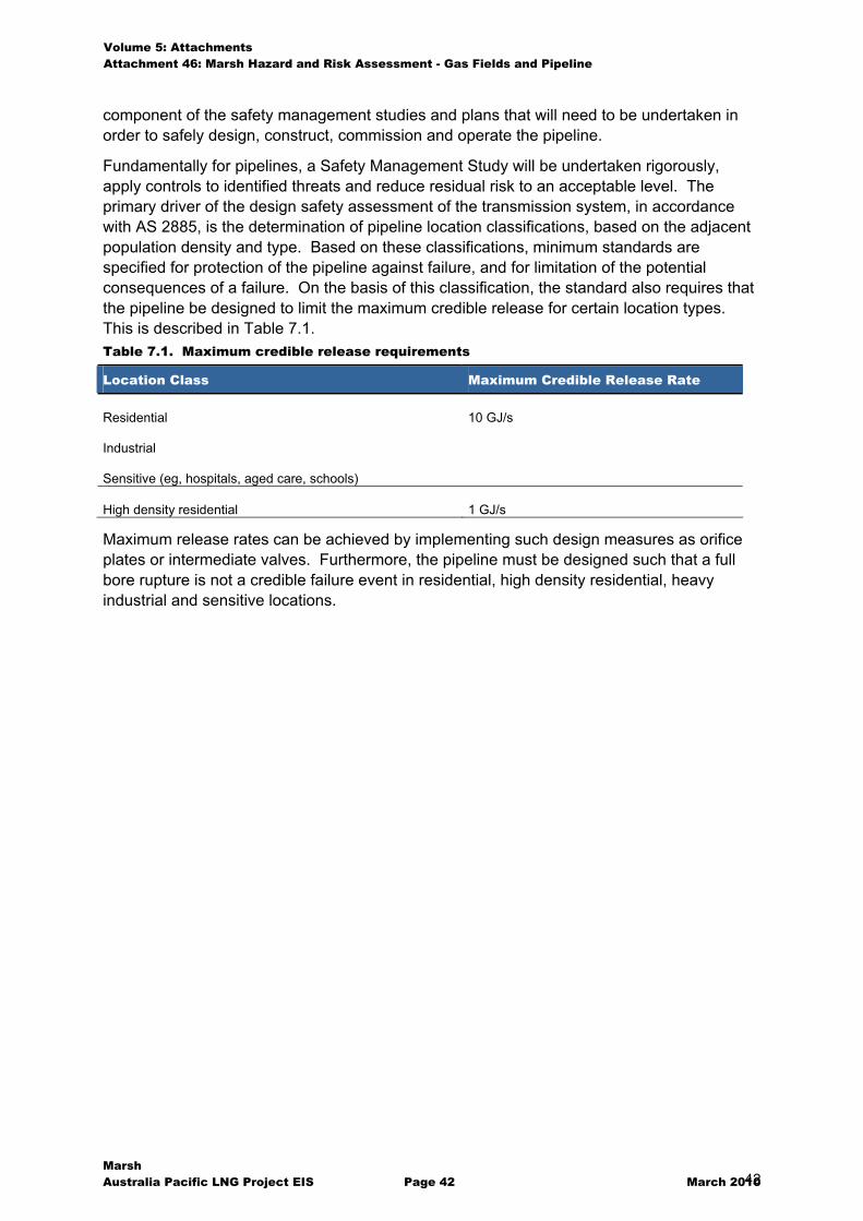
Volume 5: Attachments Attachment 46: Marsh Hazard and Risk Assessment - Gas Fields and Pipeline
Marsh Australia Pacific LNG Project EIS Page 42 March 2010 42
component of the safety management studies and plans that will need to be undertaken in order to safely design, construct, commission and operate the pipeline.
Fundamentally for pipelines, a Safety Management Study will be undertaken rigorously, apply controls to identified threats and reduce residual risk to an acceptable level. The primary driver of the design safety assessment of the transmission system, in accordance with AS 2885, is the determination of pipeline location classifications, based on the adjacent population density and type. Based on these classifications, minimum standards are specified for protection of the pipeline against failure, and for limitation of the potential consequences of a failure. On the basis of this classification, the standard also requires that the pipeline be designed to limit the maximum credible release for certain location types. This is described in Table 7.1. Table 7.1. Maximum credible release requirements
Location Class Maximum Credible Release Rate
Residential
Industrial
Sensitive (eg, hospitals, aged care, schools)
10 GJ/s
High density residential 1 GJ/s
Maximum release rates can be achieved by implementing such design measures as orifice plates or intermediate valves. Furthermore, the pipeline must be designed such that a full bore rupture is not a credible failure event in residential, high density residential, heavy industrial and sensitive locations.
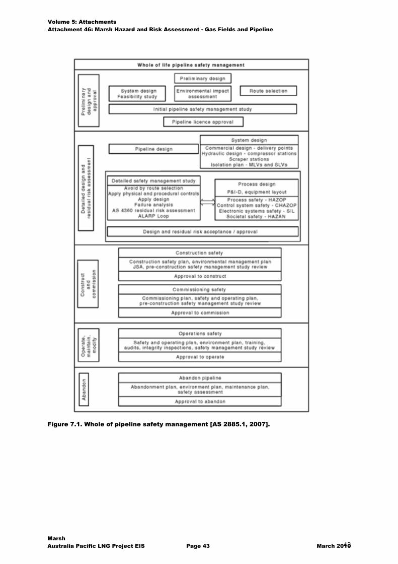
Volume 5: Attachments Attachment 46: Marsh Hazard and Risk Assessment - Gas Fields and Pipeline
Marsh Australia Pacific LNG Project EIS Page 43 March 2010 43
Figure 7.1. Whole of pipeline safety management [AS 2885.1, 2007].
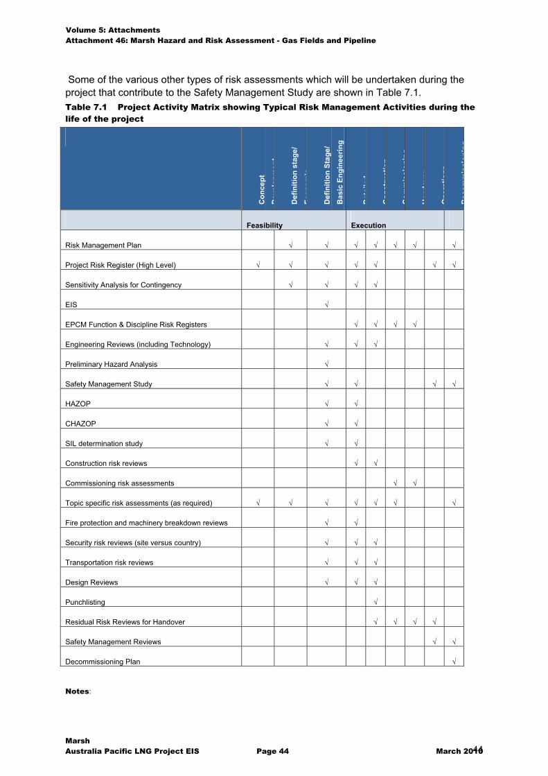
Volume 5: Attachments Attachment 46: Marsh Hazard and Risk Assessment - Gas Fields and Pipeline
Marsh Australia Pacific LNG Project EIS Page 44 March 2010 44
Some of the various other types of risk assessments which will be undertaken during the project that contribute to the Safety Management Study are shown in Table 7.1. Table 7.1 Project Activity Matrix showing Typical Risk Management Activities during the life of the project
Con
cept
Dev
elop
men
t
Def
initi
on s
tage
/
Econ
omic
Def
initi
on S
tage
/
Bas
ic E
ngin
eerin
g
Det
aile
d
Con
stru
ctio
n
Com
mis
sion
ing
Han
dove
r
Ope
ratio
ns
Dec
omm
issi
onin
g
Feasibility Execution
Risk Management Plan � � � � � � �
Project Risk Register (High Level) � � � � � � �
Sensitivity Analysis for Contingency � � � �
EIS �
EPCM Function & Discipline Risk Registers � � � �
Engineering Reviews (including Technology) � � �
Preliminary Hazard Analysis �
Safety Management Study � � � �
HAZOP � �
CHAZOP � �
SIL determination study � �
Construction risk reviews � �
Commissioning risk assessments � �
Topic specific risk assessments (as required) � � � � � � �
Fire protection and machinery breakdown reviews � �
Security risk reviews (site versus country) � � �
Transportation risk reviews � � �
Design Reviews � � �
Punchlisting �
Residual Risk Reviews for Handover � � � �
Safety Management Reviews � �
Decommissioning Plan �
Notes:
Volume 5: Attachments Attachment 46: Marsh Hazard and Risk Assessment - Gas Fields and Pipeline
Marsh Australia Pacific LNG Project EIS Page 45 March 2010 45
HAZOP - Hazard and Operability Study CHAZOP – Control Hazard and Operability Study SIL – Safety Integrity Level Topic specific risk assessments – this risk activity is included as it is typically used to assist in the decision making processes that occur along the way. Design Reviews – the focus of these reviews is on Maintenance and Operational activities and requires significant input from intended Operational and Maintenance personnel Punchlisting – focus on operability and maintainability issues at the completion (or near completion) of construction. Completed on a facility by facility basis. Residual Risk Reviews – for the Operations stage, the output effectively delivers the Area (or Facility) risk register. Any further risk reduction activity identified at this point will be considered beyond the scope of the Project and rest with Operations.
Presented below in the following sub-sections is an expanded commentary on the following key risk related activities:
� Preliminary Hazard Analysis & Process Hazard Analysis;
� Hazard and Operability (HAZOP) Studies;
� Fire Safety Study; and
� Emergency planning.
Preliminary Hazard Analysis & Process Hazard Analysis
Risk assessment for this project begins with a Preliminary Hazard Analysis which identifies the hazards contributing to an off-site risk. The preliminary hazard analysis is required to meet the requirements of the Environmental Impact Study which in turn is required to obtain development approval. As the project develops throughout the detailed design phase, the preliminary hazard analysis will evolve into a detailed Process Hazard Analysis (PHA) which will ultimately determine the comprehensive safety management requirements of the Project.
In addition to the process hazard analysis, detailed Hazard and Operability Studies (HAZOP) will be performed, Fire Safety Studies and Emergency Plans will be completed and the design will evolve toward finalisation.
Hazard and Operability (HAZOP) Studies
At the design stage of the development project, when detailed design information is available, Hazard and Operability (HAZOP) studies will be performed as an integral part of the design process. This examination identifies possible deviations from normal operating conditions which could lead to hazardous occurrences. The consequences and likelihood of such deviations are examined. Also, the adequacy and relevancy of available safeguards to detect such deviations and prevent and/or protect against their resultant effects are evaluated in detail. This process enables a comprehensive evaluation of hazard control systems and produces recommendations for any necessary modifications.
Fire Safety Study
A fire safety study's objective is to ensure that the proposed fire prevention, detection, protection and fighting measures are appropriate for the specific fire hazard and adequate to meet the extent of potential fires that could occur. These studies involve case specific hazard analysis and design of fire safety arrangements for each fire hazard so that fire systems design does not rely on the application of general codes and standards in isolation, but that suitability and effectiveness is a key consideration. The fire safety study is concerned with all the effects of fire. This study not only addresses the direct effects of flame, radiant heat and explosion but also the potential for the release of toxic materials and toxic combustion products in the event of fire and the potential for the release of

Volume 5: Attachments Attachment 46: Marsh Hazard and Risk Assessment - Gas Fields and Pipeline
Marsh Australia Pacific LNG Project EIS Page 46 March 2010 46
contaminated fire fighting water. The results of the Process Hazard Analysis and HAZOP provide the basis for fire safety requirements and the relationship between fire safety systems and emergency plans is clearly defined.
Emergency Planning
Emergency planning can reduce the impact and magnitude of an event by ensuring that when potentially dangerous situations develop the response is both quick and appropriate. Emergency procedures and plans will therefore be developed and tailored to the specific needs and hazards for all potential scenarios. The fire study, process hazard analysis and HAZOP will provide the basis for the formulation of relevant emergency procedures and of resource requirements
Other risk assessment tools
Other risk assessment tools that will be applied as the need arises (for completeness and assurance of safety management systems) will include Safety Integrity Level (SIL) for process control and Emergency Systems Survivability Analysis (ESSA). Both of these analyses focus on the robustness and survivability of process control and process safety systems in the event of a process incident.
It is important to note that these risk assessments on the operational activities will by necessity encompass start-up and shut-down phases.
Specific construction and commissioning plans will also be prepared separately.
Engineering and Design
Engineering Design
The detailed engineering design of the project will initially be founded on the basis of industry best practice and regulatory standards. The design and construction of the project will be primarily in accordance with all relevant Australian Standards of which AS 2885.1 2007 – Australian Standard for pipelines; gas and liquid petroleum, part 1 design and construction; is paramount. However, other pertinent standards and codes will be considered and in accordance with APLNG’s safety policy, it is committed to comply with or exceed all relevant legislation and standards.
Key requirements of the pipeline standard AS 2885, which limit the risk of off-site impacts are as follows:
� The development of a ‘Fracture Control Plan’;
� The standard of resistance to penetration of the pipeline. This affects the likelihood of rupture; and
� Maximum tolerable energy release rates for specified land use classes to limit the radiated heat flux generated from a fire.
By applying these standards, the maximum impact from an atypical and abnormal hazardous event can be defined.
Procedures and Training
APLNG will employ skilled operators for the commissioning, operation and decommissioning of the plant and pipeline. Over the development of the project, APLNG will work with the various engineering contractors involved in the design of the plant and pipeline to develop

Volume 5: Attachments Attachment 46: Marsh Hazard and Risk Assessment - Gas Fields and Pipeline
Marsh Australia Pacific LNG Project EIS Page 47 March 2010 47
operating procedures for the entire operation. These will include the steps for start-up, normal operations, process deviation and shut-down. Specific procedures will be developed for emergency situations and shut-down. Prior to commissioning any operating plant, a full commissioning safety plan will be developed and operators will be fully trained in these procedures as part of the safety plan.
The recruitment, procedures and training will be supported by a Health, Safety and Environmental Management System. As the nominated operator of the gas field and transmission pipeline, Origin’s HSE System will be utilised which provides a strong commitment to safety through the following commitment:
Respecting the rights and interest of the communities in which we operate by working safely and being mindful of, and attentive to, the environmental and social impact of the resources,
products and services we use or provide to others.
This commitment is supported by an operating principle which states:
We conduct ourselves and our business with due care and in accordance with relevant laws and regulations. We have an overriding duty to ensure the health and safety of our
Employees, and to minimise the health, safety and environmental impacts on our customers and the communities in which we operate.
Volume 5: Attachments Attachment 46: Marsh Hazard and Risk Assessment - Gas Fields and Pipeline
Marsh Australia Pacific LNG Project EIS Page 48 March 2010 48
Appendix B
Quantitative Risk Assessment Models This section describes the models that have been used in this study.
Consequence Modelling
Jet Flame
For this study it is assumed that when a pipeline fails, a full bore rupture and jet flame will result.
In accordance with the Australian Standard requirement, the distance to the radiation contour is calculated using Equation 20 from API RP 521, which is presented below:
KFQD�
�4
�
Where,
D = minimum distance to hazard contour, m
� = fraction of heat intensity transmitted (conservatively equal to 1)
F = fraction of heat radiated (conservatively equal to 0.25)
Q = heat release rate, kW
K = allowable radiation, kW/m2
AS 2885 requires these calculations to be conducted at quasi steady state conditions, 30 seconds after the initial release.
It is noted in AS 2885.1 the model is inherently conservative, and the actual location of the hazard contours are most likely overestimated. The AS 2885.1 model does not allow for the directional effect of momentum nor allowance wind speed. However, it is recognised that the AS 2885.1 model is specifically provided for determining location classes and not necessarily for risk assessment. For this reason, the results are also compared using the Unified Dispersion Model and the Shell Jet Flame model. These models are run via the PHAST 6.5.
Explosion
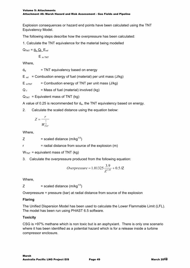
Volume 5: Attachments Attachment 46: Marsh Hazard and Risk Assessment - Gas Fields and Pipeline
Marsh Australia Pacific LNG Project EIS Page 49 March 2010 49
Explosion consequences or hazard end points have been calculated using the TNT Equivalency Model.
The following steps describe how the overpressure has been calculated:
1. Calculate the TNT equivalence for the material being modelled
QTNT = �e Qf Emf
E m TNT
Where,
�e = TNT equivalency based on energy
E mf = Combustion energy of fuel (material) per unit mass (J/kg)
E mTNT = Combustion energy of TNT per unit mass (J/kg)
Q f = Mass of fuel (material) involved (kg)
QTNT = Equivalent mass of TNT (kg)
A value of 0.25 is recommended for �e, the TNT equivalency based on energy.
2. Calculate the scaled distance using the equation below:
Zr
WTNT
� 13
Where,
Z = scaled distance (m/kg1/3)
r = radial distance from source of the explosion (m)
WTNT = equivalent mass of TNT (kg)
3. Calculate the overpressure produced from the following equation:
5.09.301325.1 85.1 ��Z
reOverpressu /Z
Where,
Z = scaled distance (m/kg1/3)
Overpressure = pressure (bar) at radial distance from source of the explosion
Flaring
The Unified Dispersion Model has been used to calculate the Lower Flammable Limit (LFL). The model has been run using PHAST 6.5 software.
Toxicity
CSG is >97% methane which is non toxic but is an asphyxiant. There is only one scenario where it has been identified as a potential hazard which is for a release inside a turbine compressor enclosure.
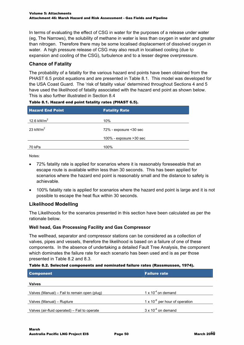
Volume 5: Attachments Attachment 46: Marsh Hazard and Risk Assessment - Gas Fields and Pipeline
Marsh Australia Pacific LNG Project EIS Page 50 March 2010 50
In terms of evaluating the effect of CSG in water for the purposes of a release under water (eg, The Narrows), the solubility of methane in water is less than oxygen in water and greater than nitrogen. Therefore there may be some localised displacement of dissolved oxygen in water. A high pressure release of CSG may also result in localised cooling (due to expansion and cooling of the CSG), turbulence and to a lesser degree overpressure.
Chance of Fatality
The probability of a fatality for the various hazard end points have been obtained from the PHAST 6.5 probit equations and are presented in Table 8.1. This model was developed for the USA Coast Guard. The ‘risk of fatality value’ determined throughout Sections 4 and 5 have used the likelihood of fatality associated with the hazard end point as shown below. This is also further illustrated in Section 8.4 Table 8.1. Hazard end point fatality rates (PHAST 6.5).
Hazard End Point Fatality Rate
12.6 kW/m2 10%
23 kW/m2 72% - exposure <30 sec
100% - exposure >30 sec
70 kPa 100%
Notes:
� 72% fatality rate is applied for scenarios where it is reasonably foreseeable that an escape route is available within less than 30 seconds. This has been applied for scenarios where the hazard end point is reasonably small and the distance to safety is achievable.
� 100% fatality rate is applied for scenarios where the hazard end point is large and it is not possible to escape the heat flux within 30 seconds.
Likelihood Modelling
The Likelihoods for the scenarios presented in this section have been calculated as per the rationale below.
Well head, Gas Processing Facility and Gas Compressor
The wellhead, separator and compressor stations can be considered as a collection of valves, pipes and vessels, therefore the likelihood is based on a failure of one of these components. In the absence of undertaking a detailed Fault Tree Analysis, the component which dominates the failure rate for each scenario has been used and is as per those presented in Table 8.2 and 8.3. Table 8.2. Selected components and nominated failure rates (Rassmussen, 1974).
Component Failure rate
Valves
Valves (Manual) – Fail to remain open (plug) 1 x 10⁻⁴ on demand
Valves (Manual) – Rupture 1 x 10⁻⁸ per hour of operation
Valves (air-fluid operated) – Fail to operate 3 x 10⁻⁴ on demand
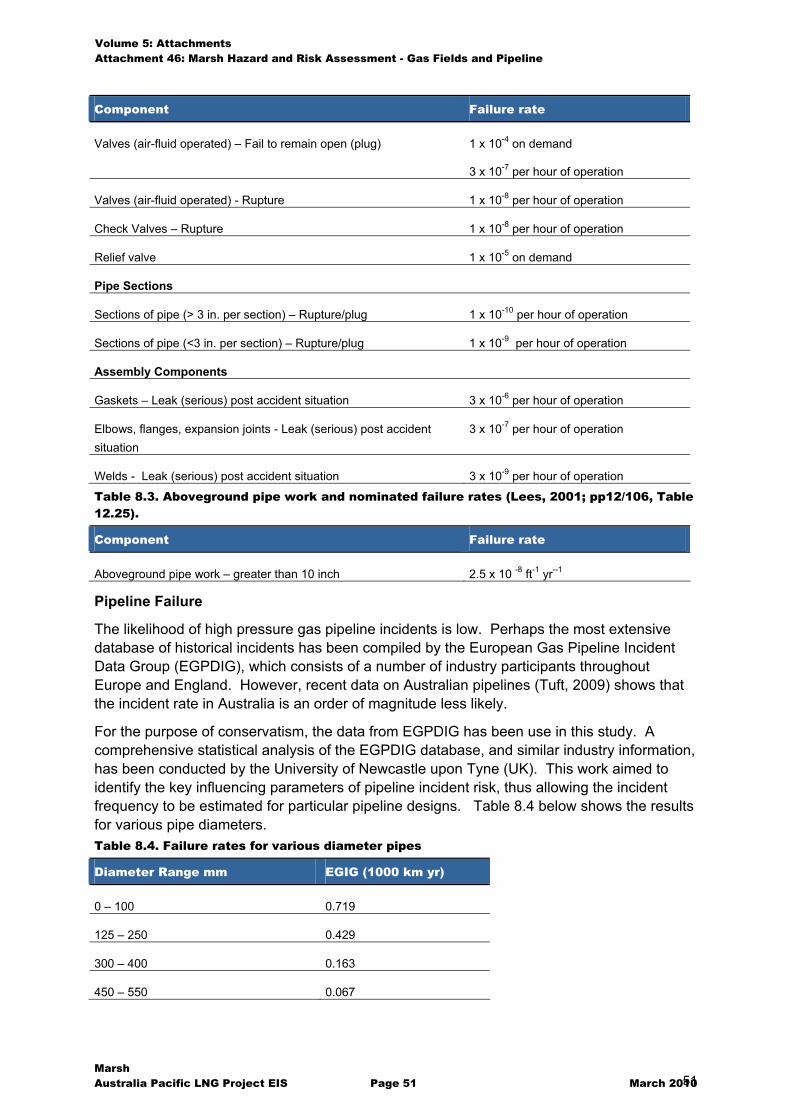
Volume 5: Attachments Attachment 46: Marsh Hazard and Risk Assessment - Gas Fields and Pipeline
Marsh Australia Pacific LNG Project EIS Page 51 March 2010 51
Component Failure rate
Valves (air-fluid operated) – Fail to remain open (plug) 1 x 10⁻⁴ on demand
3 x 10⁻⁷ per hour of operation
Valves (air-fluid operated) - Rupture 1 x 10⁻⁸ per hour of operation
Check Valves – Rupture 1 x 10⁻⁸ per hour of operation
Relief valve 1 x 10⁻⁵ on demand
Pipe Sections
Sections of pipe (> 3 in. per section) – Rupture/plug 1 x 10⁻¹⁰ per hour of operation
Sections of pipe (<3 in. per section) – Rupture/plug 1 x 10⁻⁹ per hour of operation
Assembly Components
Gaskets – Leak (serious) post accident situation 3 x 10⁻⁶ per hour of operation
Elbows, flanges, expansion joints - Leak (serious) post accident situation
3 x 10⁻⁷ per hour of operation
Welds - Leak (serious) post accident situation 3 x 10⁻⁹ per hour of operation
Table 8.3. Aboveground pipe work and nominated failure rates (Lees, 2001; pp12/106, Table 12.25).
Component Failure rate
Aboveground pipe work – greater than 10 inch 2.5 x 10 -8 ft-1 yr--1
Pipeline Failure
The likelihood of high pressure gas pipeline incidents is low. Perhaps the most extensive database of historical incidents has been compiled by the European Gas Pipeline Incident Data Group (EGPDIG), which consists of a number of industry participants throughout Europe and England. However, recent data on Australian pipelines (Tuft, 2009) shows that the incident rate in Australia is an order of magnitude less likely.
For the purpose of conservatism, the data from EGPDIG has been use in this study. A comprehensive statistical analysis of the EGPDIG database, and similar industry information, has been conducted by the University of Newcastle upon Tyne (UK). This work aimed to identify the key influencing parameters of pipeline incident risk, thus allowing the incident frequency to be estimated for particular pipeline designs. Table 8.4 below shows the results for various pipe diameters. Table 8.4. Failure rates for various diameter pipes
Diameter Range mm EGIG (1000 km yr)
0 – 100 0.719
125 – 250 0.429
300 – 400 0.163
450 – 550 0.067
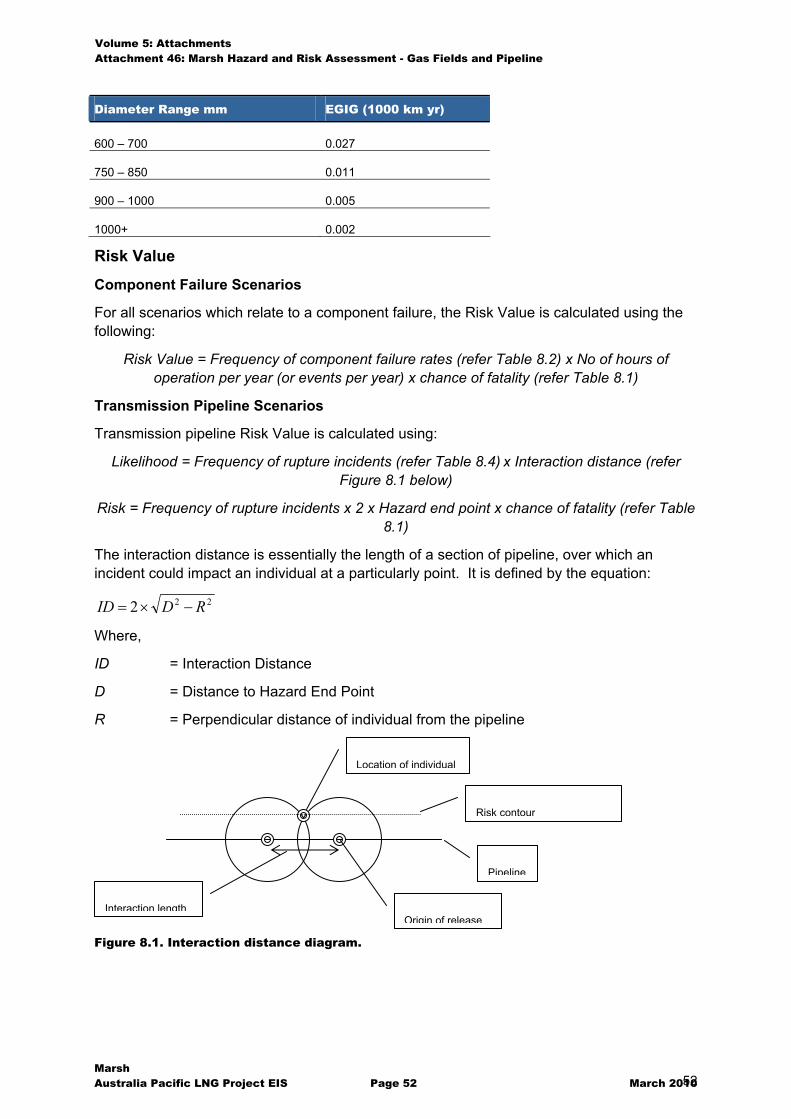
Volume 5: Attachments Attachment 46: Marsh Hazard and Risk Assessment - Gas Fields and Pipeline
Marsh Australia Pacific LNG Project EIS Page 52 March 2010 52
Diameter Range mm EGIG (1000 km yr)
600 – 700 0.027
750 – 850 0.011
900 – 1000 0.005
1000+ 0.002
Risk Value
Component Failure Scenarios
For all scenarios which relate to a component failure, the Risk Value is calculated using the following:
Risk Value = Frequency of component failure rates (refer Table 8.2) x No of hours of operation per year (or events per year) x chance of fatality (refer Table 8.1)
Transmission Pipeline Scenarios
Transmission pipeline Risk Value is calculated using:
Likelihood = Frequency of rupture incidents (refer Table 8.4) x Interaction distance (refer Figure 8.1 below)
Risk = Frequency of rupture incidents x 2 x Hazard end point x chance of fatality (refer Table 8.1)
The interaction distance is essentially the length of a section of pipeline, over which an incident could impact an individual at a particularly point. It is defined by the equation:
222 RDID ���
Where,
ID = Interaction Distance
D = Distance to Hazard End Point
R = Perpendicular distance of individual from the pipeline
Figure 8.1. Interaction distance diagram.
Location of individual
Origin of release
Risk contour
Pipeline
Interaction length
Volume 5: Attachments Attachment 46: Marsh Hazard and Risk Assessment - Gas Fields and Pipeline
Marsh Australia Pacific LNG Project EIS Page 53 March 2010 53
Appendix C
Unified Dispersion Model
Volume 5: Attachments Attachment 46: Marsh Hazard and Risk Assessment - Gas Fields and Pipeline
Marsh Australia Pacific LNG Project EIS Page 62 March 2010 62
Appendix D
Shell Jet Flame Model
Volume 5: Attachments Attachment 46: Marsh Hazard and Risk Assessment - Gas Fields and Pipeline
Marsh Australia Pacific LNG Project EIS Page 72 March 2010 72
Appendix E
References AS 2885.1 (2007), Pipelines – Gas and Liquid Petroleum, Part 1: Design and Construction, Standards Australia, Sydney, Australia.
CH·IV International, December 2006, Technical Document TD-02109, Safety History of International LNG Operations. Available from: www.CH-IV.com
EN 1473 (1997), Installation and Equipment for Liquefied Natural Gas – Design of Onshore Installations, European Standard EN 1473, British Standard BS EN 1473, British Standards Board.
Fedoroff, B. T. and Sheffield, O. E. in Reese , E. A. and Clift, G.D., “Encyclopaedia of Explosives and Related Items”, Vol.1, 1960, Picatinny Arsenal.
Foss M.M., October 2003, LNG Safety and Security, Centre for Energy Economics at the Bureau of Economic Geology, the University of Texas at Austin. Available from: http://www.energy.ca.gov/lng/safety.html
HIPAP 4 (1992), Hazardous Industry Planning Advisory Paper No. 4 – Risk Criteria for Land Use Safety Planning, New South Wales Department of Planning, Sydney, Australia.
Institute of Chemical Engineers, “Explosions in the process industries”, Second edition, 1994
Lees, F. P., 2001, Loss Prevention in the Process Industries – Hazard Identification, Assessment and Control, 2nd Edition, Butterworth-Heinemann, Oxford, UK.
Leis, B. N., Pimputkar, S. M., Ghadiali, N. D., „Line rupture and the spacing of parallel lines“, Pipeline Research Council International, Catalog No. L51861, April 2002
McKetta J.J., Encyclopaedia of chemical processing and design, Vol. 36, Pipeline Failure
Rasmussen, N. C. 1974, The AEC study on the estimation of risks to the public from potential accidents in nuclear power plants, Nuclear Safety, 15, 375.
Tuft, P., “Experience with the Australian pipeline incident database”, presentation at the APIA Convention, October, 2009.
Tweeddale M., 1998, Process Plant Risk Management, The University of Sydney, Department of Chemical Engineering.

Marsh Pty Ltd ABN 86 004 651 512 Riverside Centre 123 Eagle Street BRISBANE QLD 4000 GPO Box 2743 BRISBANE QLD 4001 61 7 3115 4555