Embed Size (px)
Citation preview
AutAutAutAutomaticomaticomaticomatic PartPartPartPart PrimitivePrimitivePrimitivePrimitive FeatureFeatureFeatureFeature Identification Based on Identification Based on Identification Based on Identification Based on
Faceted ModelsFaceted ModelsFaceted ModelsFaceted Models
Gandjar Kiswanto1 and Muizuddin Azka2
1 Department of Mechanical Engineering, Universitas Indonesia
Depok, 16424, Indonesia
2 Department of Mechanical Engineering, Universitas Indonesia
Depok, 16424, Indonesia
Abstract Feature recognition technology has been developed along with
the process of integrating CAD/CAPP/CAM. Automatic feature
detection applications based on faceted models expected to
speed up the manufacturing process design activities such as
setting tool to be used or required machining process in a variety
of different features. This research focuses on detection of
primitive features available in a part. This is done by applying
part slicing and grouping adjacent facets. Type of feature is
identified by simply evaluating normal vector direction of all
features group. In order to identify features on various planes of
a part, planes, one at a time, are rotated to be parallel with the
reference plane. The results showed that this method can identify
the primitive features automatically accurately in all planes of
tested part, this covered : pocket, cylindrical and profile feature.
Keywords: Feature Recognition, Grouping, Normal Vector,
Faceted Models.
1. Introduction
The feature recognition of a part is the most important
section of the design optimization process in CAPP and
CAM. The basic principle of the feature recognition is to
speed up decision-making system on the activity of the
manufacturing process planning. This will help determine
what processes are required, what tool to use, and any
other things to become more efficient. Primitive features of
a part, such as : pocket, cylindrical, and profile is a
common form used. Identification of primitive feature will
automatically save time and effort in the process planing.
Various methods have been established to develop feature
identification automatically. V.B. Sunil and S.S. Pande
designed and implemented automatic feature recognition
system freeform surface CAD models of sheet metal in the
STL format. [1]. R. Abu and Masine detected feature
recognition automatically through the model of B-rep
based TNOF, TNOE, TOF, and P/D [2].
G. Kiswanto and A. Yahya develop identification Closed
Bounded Volume (CBV) in a complex faceted models
through Paired Normal Vectors Bucketing method
(PNVB) for automatic tool-path planning [3]. Raymond et
al. presented algorithm to identify features by
implementing the octree representation of B-rep models
for locating features on the assembly process [4].
C. Weber and S. Hahmann presents a new technique to
detect a sharp feature in the point cloud geometry using the
Gauss map clustering and selection process of iteration [6].
G. Kiswanto, R. Widyanto and P.E. Kreshna developed
surface feature identification in the form of flat, saddle,
convex, and concave with a combined method of Gauss
Bonnet and Spherical Image [10].
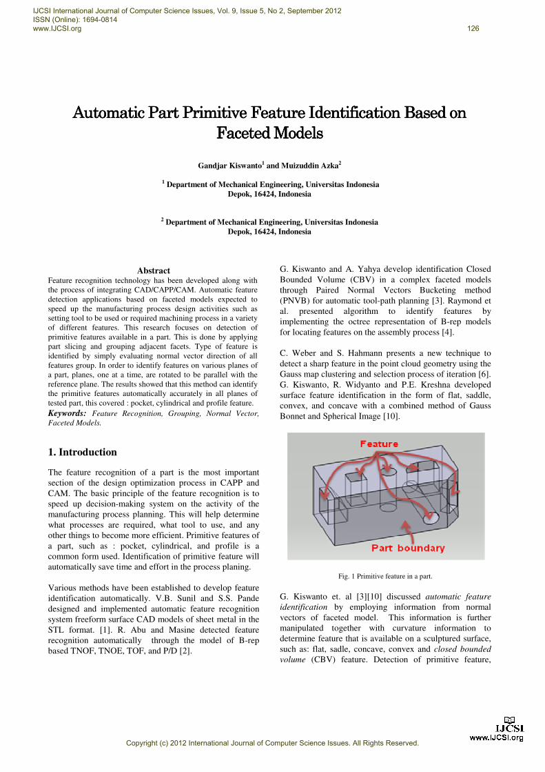
Fig. 1 Primitive feature in a part.
G. Kiswanto et. al [3][10] discussed automatic feature
identification by employing information from normal
vectors of faceted model. This information is further
manipulated together with curvature information to
determine feature that is available on a sculptured surface,
such as: flat, sadle, concave, convex and closed bounded
volume (CBV) feature. Detection of primitive feature,
IJCSI International Journal of Computer Science Issues, Vol. 9, Issue 5, No 2, September 2012 ISSN (Online): 1694-0814 www.IJCSI.org 126
Copyright (c) 2012 International Journal of Computer Science Issues. All Rights Reserved.

such as : pocket, cylindrical, and profile, on prismatic part
based on faceted models by utilizing normal vector
information still needs to be investigated further (Fig. 1).
Therefore, this paper presented research focused on this
one.
2. Faceted Models
Processing faceted models data structure is needed since
the information from the data STL-files cannot be directly
used. Data of STL-files need to be processed first so as to
structure the data in a coordinate system. STL format is the
most commonly used because it is easier to read and
understand and can be opened in any text editor for further
evaluation when necessary. The STL Files (ASCII format)
contains the following data :
solid
facet normal ------- ------- -------
outer loop
vertex ------- ------- -------
vertex ------- ------- -------
vertex ------- ------- -------
ensloop
endfacet
-------
-------
end
STL file format stores objects in a 3D surface triangles
composed three (3) vertices that are at a particular location
in a 3D coordinate system. Here is an explanation of the
contents of the STL file above:
1 SOLID marks the beginning of a faceted models
representation to be closed with the word
ENDSOLID
2 FACET NORMAL indicates that there will be a
triangular surface with normal vector value is the
vector direction after the FACET NORMAL to
meet with ENDFACET which means a surface
triangle was formed, and their sequence information
and the location of the vertex, and the normal
vector of the triangle them
3 OUTER LOOP marks the beginning of the loop of
the coordinates of the vertices are built of the
triangle to meet with ENDLOOP
4 VERTEX is the point of making up a triangle that
has previously been defined by the OUTER LOOP.
Information that was once the word VERTEX is the
position of a point on a 3D coordinate system
Reading of normal vector direction is used to assist in the
rotating part or feature identification that has certain
characteristics. Normal vector direction of the triangle will
be in accordance with the order of vertex, normal vector in
seeking to follow the right hand rule. If clockwise rotation,
then the normal vector will lead the plane. Conversely, if
the rotation is counter clockwise, then the normal vector
out of the plane. This can be explained in the figure below.
Fig. 2 Normal vector following the right hand rule.
As shown in Figure 2(a) and 2(b) above, the order of
vertices data is in counter-clockwise. Then, by following
the right hand rule, the normal vector, as a result of cross
product between the vectors connecting the vertices, is
pointing out the plane accordingly. While in Figure 2(b),
the normal vector is pointing into the plane.
3. Algorithm Development
A faceted model is a representation of a solid model in
triangular mesh form. The surface is tessellated logically
into a set of oriented triangles (facets). Entities such as
points, lines, curves, and attributes such as layer, color, in
the CAD systems will be ignored. Since the solid model is
represented by mesh of triangles, the shape of the
triangulation result is an approximation. The accuracy
depends much on triangulation resolution. Higher the
resolution, better the shape we get.
The facets are arranged by certain rules. Each facet is
uniquely recognized by a unit normal and three vertices. A
vertex will only meet other vertices, also an edge will only
meet another edge. The normal vector will define the facet
orientation. Commonly, the direction of the normal is
outward. It will be applied consistently through all the
facets. By that, one can simply define which part is outside
and which part is inside for the whole model. All these
data is kept in a list, usually in STL format. Framework of
research automatic part primitive feature identification
based on faceted models is done by steps algorithm
in Fig. 3.
Step of feature identification algorithm begins with the
processing of data structures and detecting outer normal
vector to the STL file that contains information about the
data facet and three vertices of each triangle forming.
IJCSI International Journal of Computer Science Issues, Vol. 9, Issue 5, No 2, September 2012 ISSN (Online): 1694-0814 www.IJCSI.org 127
Copyright (c) 2012 International Journal of Computer Science Issues. All Rights Reserved.
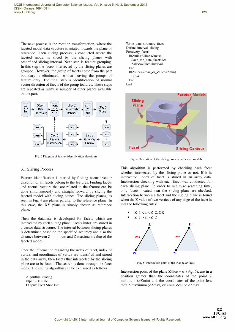
The next process is the rotation transformation, where the
faceted model data structure is rotated towards the plane of
reference. Then slicing process is conducted where the
faceted model is sliced by the slicing planes with
predefined slicing interval. Next step is feature grouping.
In this step the facets intersected by the slicing planes are
grouped. However, the group of facets come from the part
boundary is eliminated, so that leaving the groups of
feature only. The final step is identification of normal
vector direction of facets of the group features. These steps
are repeated as many as number of outer planes available
on the part.
Fig. 3 Diagram of feature identification algorithm.
3.1 Slicing Process
Feature identification is started by finding normal vector
direction of all facets belong to the features. Finding facets
and normal vectors that are related to the feature can be
done simultaneously and straight forward by slicing the
faceted model with slicing planes. The slicing planes, as
seen in Fig. 4 are planes parallel to the reference plane. In
this case, the XY plane is simply chosen as reference
plane.
Then the database is developed for facets which are
intersected by each slicing plane. Facets index are stored in
a vector data structure. The interval between slicing planes
is determined based on the specified accuracy and also the
distance between Z-minimum and Z-maximum value of the
faceted model.
Once the information regarding the index of facet, index of
vertex, and coordinates of vertex are identified and stored
in the data array, then facets that intersected by the slicing
plane are to be found. The search is done through the facet
index. The slicing algorithm can be explained as follows.
Algorithm: Slicing
Input: STL File
Output: Facet Slice File
Write_data_structure_facet
Define_interval_slicing
For(every_facet)
If(Zmin<Zslice<Zmax)
Save_the_data_facetslice
Zslice=Zslice+interval
End
If(Zslice>Zmax_or_Zslice<Zmin)
Break
End
End
Fig. 4 Illustration of the slicing process on faceted models
This algorithm is performed by checking each facet
whether intersected by the slicing plane or not. If it is
intersected, index of facet is stored in an array data.
Intersection checking with each facet was conducted for
each slicing plane. In order to minimize searching time,
only facets located near the slicing plane are checked.
Intersection between a facet and the slicing plane is found
when the Z-value of two vertices of any edge of the facet is
met the following rules:
• Z_1 < z < Z_2, OR
• Z_1 > z > Z_2
Fig. 5 Intersection point of the triangular facet.
Intersection point of the plane Zslice = c (Fig. 5), are in a
position greater than the coordinates of the point Z
minimum (>Zmin) and the coordinates of the point less
than Z maximum (<Zmax) or Zmin <Zslice <Zmax.
IJCSI International Journal of Computer Science Issues, Vol. 9, Issue 5, No 2, September 2012 ISSN (Online): 1694-0814 www.IJCSI.org 128
Copyright (c) 2012 International Journal of Computer Science Issues. All Rights Reserved.
3.2 Feature Grouping
Other information that is necessary for detecting features is
the facets connectivity information. The adjacent facets
method is used to determine the facet connectivity. Every
edge of a facet, thus the two vertices that form the edge, is
shared by another facet. Once an edge of a facet is found to
be intersected by the slicing plane, other facet who shares
the same edge can be found easily. This procedure is run
for the rest of process until no more new facet is identified.
Furthermore, for each slicing, all facets which are
intersected and are adjacent facets are grouped in the same
of group of adjacent facets. Two or more different slicing
might intersect the same facet. However, only different
facets are finally grouped to form an adjacent group. All
adjacent group data are stored in the so called Group
Matrix.
To obtain group of features, all adjacent facet groups are
evaluated. This evaluation produces the so called Adjacent
Groups which are candidates of groups for Feature
Grouping. In Feature Grouping, groups of adjacent facets
that belong to part boundaries are eliminated. The part
boundary is the group of adjacent facets that having
outermost normal vector. Algorithm of Grouping Feature
can be seen as follows:
Algorithm: Feature Grouping
Input: Intersected Facets
Output: Feature Group Data
Write_data_facetslice
For(every_facetslice)
If(data_facetslice_unique)
Save_the_data_GroupMatrix
End
End
Write_data_GroupMatrix
For(every_facet_GroupMatrix)
If(adjacent_triangles)
Save_the_data_GroupAdjacent
End
End
Write_data_GroupAdjacent
For(every_GroupAdjacent)
Find(group_part_boundary)
Eliminate_group_part_boundary
End
End
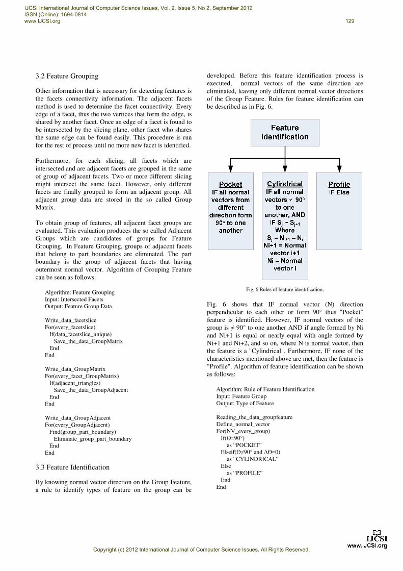
3.3 Feature Identification
By knowing normal vector direction on the Group Feature,
a rule to identify types of feature on the group can be
developed. Before this feature identification process is
executed, normal vectors of the same direction are
eliminated, leaving only different normal vector directions
of the Group Feature. Rules for feature identification can
be described as in Fig. 6.
Fig. 6 Rules of feature identification.
Fig. 6 shows that IF normal vector (N) direction
perpendicular to each other or form 90° thus "Pocket"
feature is identified. However, IF normal vectors of the
group is ≠ 90° to one another AND if angle formed by Ni
and Ni+1 is equal or nearly equal with angle formed by
Ni+1 and Ni+2, and so on, where N is normal vector, then
the feature is a "Cylindrical". Furthermore, IF none of the
characteristics mentioned above are met, then the feature is
"Profile". Algorithm of feature identification can be shown
as follows:
Algorithm: Rule of Feature Identification
Input: Feature Group
Output: Type of Feature
Reading_the_data_groupfeature
Define_normal_vector
For(NV_every_group)
If(Ө=90°)
as “POCKET”
Elseif(Ө≠90° and ∆Ө≈0)
as “CYLINDRICAL”
Else
as “PROFILE”
End
End
IJCSI International Journal of Computer Science Issues, Vol. 9, Issue 5, No 2, September 2012 ISSN (Online): 1694-0814 www.IJCSI.org 129
Copyright (c) 2012 International Journal of Computer Science Issues. All Rights Reserved.

4. Implementation and Result
The method described above, is implemented in 3D CAD
model as shown in Fig. 7. The model consists of pocket,
cylindrical, and profile in direction [0 0 1], cylindrical
feature in direction [0 1 0], profile feature in direction [1 0
0], and pocket feature in the direction [-0.707 0.707 0].
Fig. 7 3D CAD Model.
The 3D CAD model is then processed (triangulated) to
form faceted model. The data structure is developed based
on this faceted model. Then, the planes of outer normal
vector are to be found to start feature identification. The
detected outer plane (by finding outer normal vector) is
rotated to be aligned (parallel) to the reference plane (Fig.
8). Slicing process is then performed, and continued by
feature grouping and feature identification. This step is
repeated according to the number of planes of the outer
normal vector which are detected.
(a) (b) (c) (d)
Fig. 8 The illustration of rotation transformation.
Slicing process, feature grouping and feature identification
are explained as follows. For example, outer normal vector
of detected outer plane is in direction [0 0 1] (Fig. 8(d)).
To simplify feature identification process, all features that
are located on planes which are sliced by the slicing plane
are ignored. In other words, only features which are
located on the planes parallel to the reference plane
(slicing plane) are considered. This process is repeated as
many as number of detected outer planes. An example of
slicing process can be seen in Fig. 9 shown below where
four slicings are conducted. The distance of first slicing
plane with respect to the reference plane is determined to
be half of the predefined slicing interval.
Fig. 9 View slicing the XY plane.
The results of each slicing can be seen in Fig. 10. In Slice
1, the intersection occurs with the part boundary only,
while in Slice 2, the intersection is with part boundary and
cylindrical feature. Slice 3 shows intersection with part
boundary, pocket, cylindrical, and bottom part of profile
feature. Slice 4 intersects with part boundary, pocket,
cylindrical, and the upper profile feature (Fig. 10).
Slice 1
Slice 2
Slice 3
Slice 4
Fig. 10 View the result of XY plane slicing.
As explained above, Feature Grouping is carried out
through several steps: Sorting, development of Group
Matrix, and Adjacent Facets grouping. The following
figure shows data transformation to form feature grouping
(Fig. 11).
The final process is Feature Identification. This is done
through the rule explained in section 3.3 and as shown in
Fig. 6. The following figure (Fig. 12) shows the result of
feature identification evaluated on only one outer plane
which is aligned with the reference plane.
IJCSI International Journal of Computer Science Issues, Vol. 9, Issue 5, No 2, September 2012 ISSN (Online): 1694-0814 www.IJCSI.org 130
Copyright (c) 2012 International Journal of Computer Science Issues. All Rights Reserved.
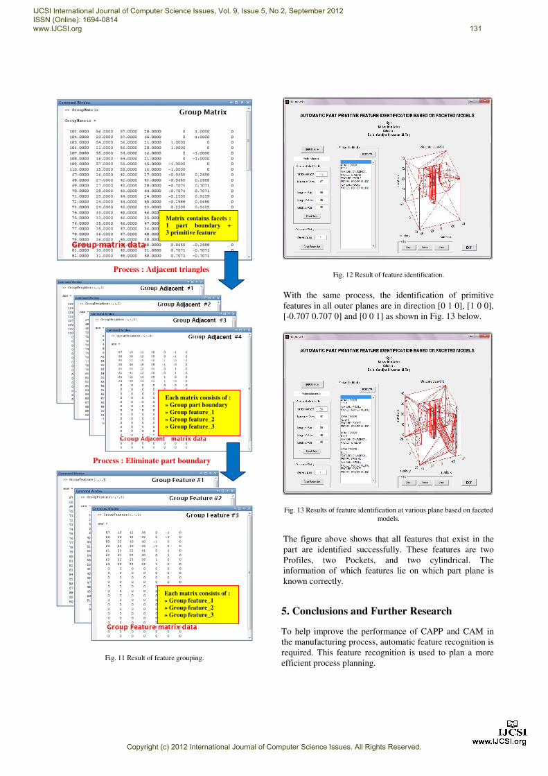
Fig. 11 Result of feature grouping.
Fig. 12 Result of feature identification.
With the same process, the identification of primitive
features in all outer planes are in direction [0 1 0], [1 0 0],
[-0.707 0.707 0] and [0 0 1] as shown in Fig. 13 below.
Fig. 13 Results of feature identification at various plane based on faceted
models.
The figure above shows that all features that exist in the
part are identified successfully. These features are two
Profiles, two Pockets, and two cylindrical. The
information of which features lie on which part plane is
known correctly.
5. Conclusions and Further Research
To help improve the performance of CAPP and CAM in
the manufacturing process, automatic feature recognition is
required. This feature recognition is used to plan a more
efficient process planning.
Each matrix consists of :
» Group part boundary
» Group feature_1
» Group feature_2
» Group feature_3
Each matrix consists of :
» Group feature_1
» Group feature_2
» Group feature_3
Process : Eliminate part boundary
Matrix contains facets :
1 part boundary +
3 primitive feature
Process : Adjacent triangles
IJCSI International Journal of Computer Science Issues, Vol. 9, Issue 5, No 2, September 2012 ISSN (Online): 1694-0814 www.IJCSI.org 131
Copyright (c) 2012 International Journal of Computer Science Issues. All Rights Reserved.

This paper discusses a method of feature grouping and
identification by simply employing normal vector
information and facets relationships (adjacency) of a
faceted model. The developed method is able to detect and
identify Pocket, Cylindrical, and Profile feature on a part.
Further research is to identify a more complex feature by
also considering the facets adjacency. The identification
should be able to mention number of different common
planes within the feature.
References [1] V.B. Sunil and S.S. Pande, “Automatic Recognition of
Feature from Freeform Surface CAD Models” Elsevier,
Vol. 40, 2008, pp. 502 – 517.
[2] R. Abu and M. MD. Tap, “Attribute Based Feature
Recognition for Machining Features” Jurnal Teknologi,
Vol. 46(A), 2007, pp. 87 – 103.
[3] G. Kiswanto and A. Yahya, “Development of Closed
Bounded Volume (CBV) Grouping Method of Complex
Faceted Model through CBV Boundaries Identification” in
2010 The 2nd International Conference on Computer and
Automation Engineering, Vol. 1, 2010, pp. 378 – 382.
[4] C. W. Raymond, J. S. Corney, and D. E. R. Clark, “Octree
Based Recognition of Assembly Features,” in ASME 2000
Design Engineering Technical Conferences and Computer
and Information in Engineering Conferences, 2000,
pp. 1-10.
[5] M. P. Bhandarkar and R. Nagi, “STEP Based Feature
Extraction from STEP Geometry for Agile Manufacturing”,
Elsevier, Vol. 41, 2000, pp. 3 – 24.
[6] C. Weber, S. Hahmann, H. Hagen, “Sharp Feature
Detection in Ploint Clouds”, in IEEE International
Conference on Shape Modeling and Applications (SMI),
2010.
[7] G. Kiswanto and A. Mujahid, “Rapid Algorithm
Development with Determination Cutter Contact Point
CAM System Based on Faceted Models for Machining
Roughing and Finishing”, in Prociding SNTTM V,
University of Indonesia, Jakarta, 2006.
[8] Francesco Bianconi, “Bridging The Gap between CAD and
CAE using STL files”, International Journal of CAD/CAM
Vol. 2, No. 1, 2002, pp. 55-67.
[9] P. Lefebvre and B. Lauwers, “STL Model Segmentation for
Multi-Axis Machining Operations Planning”, Computer
Aided Design and Applications, Vol. 1, 2004, pp. 277-284.
[10] G. Kiswanto, R. Widyanto and P.E. Kreshna, “Feature Based Milling Direction of a Faceted Model Based on Intelligent Fuzzy 3D Feature Identification”, http://ui.academia.edu
Gandjar Kiswanto is a lecturer in the Departement of Mechanical Engineering Faculty of Engineering Universitas Indonesia. He earned bachelor degree in Mechanical Engineering Universitas Indonesia in 1995. He completed his master and doctoral education of Production Engineering, Machine Design, Automation fields in the Departement Werktuigkunde - KU. Leuven in 1998 and 2003. In the structure of the department, He served as Secretary of the Department and Head of Design, Manufacturing and
Automation Sciences in Department of Mechanical Engineering. Some of his scientific publications are produced, is Development of Multi-Axis Force Detector for 5-DOF Articulated Robot, Design of Walking Posture of Humanoid Robot based on COG Stability, Development of Prototype of Hybrid Vehicle Controller. His current research interests are in Automatic Feature Recognition and Augmented Machining Process.
Muizuddin Azka is a engineer in BPPT (Agency for The Assessment and Application of Technology). He earned bachelor degree in Mechanical Engineering Universitas Sebelas Maret in 2005 and completed his master education in Mechanical Engineering Universitas Indonesia in 2012.
IJCSI International Journal of Computer Science Issues, Vol. 9, Issue 5, No 2, September 2012 ISSN (Online): 1694-0814 www.IJCSI.org 132
Copyright (c) 2012 International Journal of Computer Science Issues. All Rights Reserved.