Embed Size (px)
Citation preview
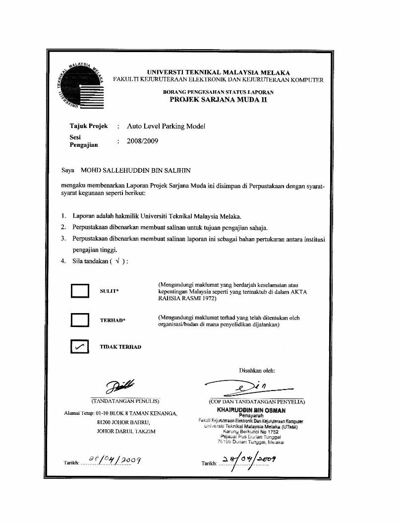
AUTO LEVEL PARKING MODEL
MOHD SALLEHUDDIN BIN SALIHIN
This report is submitted in partial fulfillment of the requirement for the award of
Bachelor of Electronic Engineering (Industrial Electronic) With Honors
Faculty of Electronic and Computer Engineering
Universiti Teknikal Malaysia Melaka
April 2009


v
Specially dedicated to
my beloved parents, brothers, and sisters who have encouraged, guided and inspired
me throughout my journey of education.

vi
ACK�OWLEDGEME�T
First of all, I would like to take this opportunity to express my deepest
gratitude to my beloved project supervisor, Mr. Khairuddin Bin Osman for his
guidance, encouragement and endurance during the whole course of this project. It is
indeed my pleasure for his undivided support, invaluable advices and enthusiastic
support to make my project a successful done. My special gratitude is to my beloved
family, especially my parents for their fullest support throughout my 3 year’s study
in Universiti Teknikal Malaysia Melaka (UTeM). It is because of them, I am the
person who I am today. For all their moral support all these while so that I will be
able to complete my project successfully. My appreciation to my friends especially
my course mates, for their technical advice and material aid. To all the people that
assist me directly and indirectly in this project, once again I would like to say a big
thank you. Thank you.
vii
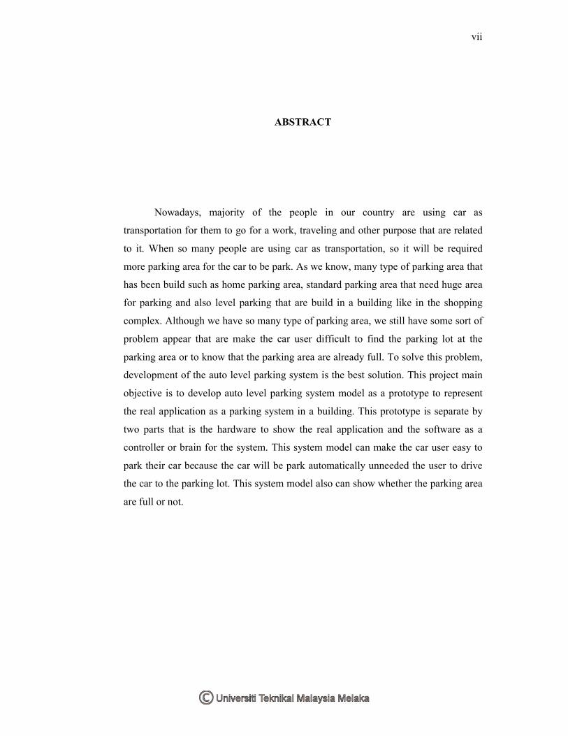
ABSTRACT
Nowadays, majority of the people in our country are using car as
transportation for them to go for a work, traveling and other purpose that are related
to it. When so many people are using car as transportation, so it will be required
more parking area for the car to be park. As we know, many type of parking area that
has been build such as home parking area, standard parking area that need huge area
for parking and also level parking that are build in a building like in the shopping
complex. Although we have so many type of parking area, we still have some sort of
problem appear that are make the car user difficult to find the parking lot at the
parking area or to know that the parking area are already full. To solve this problem,
development of the auto level parking system is the best solution. This project main
objective is to develop auto level parking system model as a prototype to represent
the real application as a parking system in a building. This prototype is separate by
two parts that is the hardware to show the real application and the software as a
controller or brain for the system. This system model can make the car user easy to
park their car because the car will be park automatically unneeded the user to drive
the car to the parking lot. This system model also can show whether the parking area
are full or not.

viii
ABSTRAK
Pada masa kini, kebanyakan dari pada rakyat di negara kita menggunakan
kereta sebagai pengangkutan utama untuk mereka pergi bekerja, mengembara atau
apa sahaja aktiviti yang menggunakan kereta sebagai pengangkutan. Oleh kerana
terlalu ramai yang menggunakan kereta sebagai pengangkutan utama, maka
keperluan kawasan tempat meletak kenderaan juga semakin meningkat dari semasa
ke semasa. Seperti yang diketahui, perbagai jenis tempat meletak kenderaan telah
dibina seperti kawasan meletak kenderaan di rumah, kawasan meletak kenderaan
biasa yang memerlukan kawasan yang luas, kawasan meletak kenderaan secara
bertingkat di dalam bangunan dan juga bawah tanah. Walaupun mempunyai perbagai
jenis kawasan meletak kenderaan, masih lagi timbul beberapa masalah yang
berkaitan seperti sukar untuk mencari tempat meletak kenderaan atau sukar untuk
mengetahui sama ada kawasan meletak kenderaan tersebut sudah penuh atau tidak.
Cara terbaik untuk mengatasi masalah tersebut adalah dengan terciptanya sistem
meletak kenderaan bertingkat secara automatik ini. Objektif utama projek ini adalah
untuk mencipta model ataupun prototaip yang berfungsi untuk meletak kenderaan
secara automatik bagi menggambarkan aplikasi yang sebenar sistem ini. Prototaip
projek ini terbahagi kepada dua bahagian iaitu rangka serta komponen yang lengkap
dan juga program. Bahagian program ialah bahagian yang akan mengawal segala
aturcara sistem dan boleh dikatakan sebagai perancang dalam sistem ini. Sistem
meletak kenderaan bertingkat secara automatik ini akan memudahkan pengguna
kenderaan untuk meletak kenderaan mereka tanpa perlu memandu ke tempat meletak
kenderaan dan sistem ini juga dapat memberitahu pengguna bahawa kawasan
meletak kenderaan tersbut sudah penuh.
ix
TABLE OF CO�TE�TS
CHAPTER TITLE PAGE
PROJECT TITLE i
REPORT STATUS FORM ii
DECLARATIO� iii
ACK�OWLEDGEME�T vi
ABSTRACT vii
ABSTRAK viii
TABLE OF CO�TE�TS ix
LIST OF TABLES xii
LIST OF FIGURES xiii
LIST OF APPE�DIXS xv
I I�TRODUCTIO�
1.1 Project Overview 1
1.2 Project Objectives 2
1.3 Project Problem Statement 2
1.4 Project Scope 3
1.5 Project Methodology 3
1.5.1 Project Process Flow 3
1.6 Thesis Outline 5
II LITERATURE REVIEW
2.1 Control Of A Four-Level Elevator System
Using a Programmable Logic Controller 6
x
2.1.1 Hardware Design 7
2.1.2 Description Of The Interface Circuit 8
2.1.3 Description Of The Control Panel 8
2.2 Automated Multistoried Car Parking System 10
2.2.1 System Flow 11
2.2.2 Hardware Description 12
2.3 DC Motor 15
2.4 Microchip PIC16F877A 16
2.5 IC L293D (Quadruple Half-H Driver) 19
2.6 Transmitter and Receiver Photodiode 21
2.7 IC LM324 (Quad Operational Amplifier) 22
III METHODOLOGY
3.1 Project Design 24
3.2 Project System Controller 26
3.2.1 System Input and Output 26
3.2.2 The Usage of PIC16F877A 27
3.2.3 Inputs and Outputs Connection to the
PIC16F877A 28
3.3 Motor Controller 29
3.4 Level Sensor 30
3.4.1 Position of the Sensor 31
3.5 Voltage Regulator 32
3.6 Project System Flowchart 32
3.6.1 Elevator Analysis 32
3.6.2 Parking Car 34
3.6.3 Return Car 35
3.7 Project Methodology 36
xi
IV A�ALYSIS
4.1 Forward and Reverse Motor Controller 40
4.2 Motor Speed Controller 42
4.3 Elevator Motor Load Analysis 43
4.4 Infrared Sensor Analysis 45
V RESULT A�D DISCUSSIO�
5.1 Auto Level Parking Model 48
5.1.1 Position of the Power Supply 50
5.1.2 Position of the Switch Controller 50
5.2 Discussion 52
VI CO�CLUSIO� A�D RECOMME�DATIO�
6.1 Conclusion 54
6.2 Recommendation 55
REFERE�CES 56
xii
LIST OF TABLES
�O TITLE PAGE
2.1 List and Definition of Input and Output Used 9
2.2 PIC16F877A Device Features 17
2.3 L293D Function Table 20
3.1 System Input and Output 26
3.2 L293D Function Table Control Motor 29
3.3 IR Sensor Detection 31
3.4 Project Methodology 39
4.1 Voltage Drop Effect on the Load 44
xiii
LIST OF FIGURES
�O TITLE PAGE
1.1 Project Flowchart 4
2.1 Block Diagram of the System Layout 7
2.2 General Scheme for the Used of an S/R Flip Flop 9
2.3 Overall Layout of the Control Panel of the Elevator 10
2.4 System Hardware 11
2.5 Usual CPU Components Program Counter, ALU,
Working Registers, and the Clock Circuits 14
2.6 Mabuchi DC Motor Series 15
2.7 PIC 16F877A 16
2.8 Pin Diagram for PIC 16F877A Microcontroller 16
2.9 Block Diagram for PIC 16F877A Microcontroller 18
2.10 Top View of L293D 19
2.11 L293D Block Diagram 20
2.12 Transmitter and Receiver Photodiode 21
2.13 IC LM324 22
2.14 IC LM324 Block Diagram 22
3.1 Project Model Front View 25
3.2 Project Model Side View 25
3.3 Pin Diagram for PIC16F877A Microcontroller 27
3.4 PIC16F877A Input and Output Connection 28
3.5 L293D Block Diagram and Motor 29
3.6 Circuit diagram for the Level Sensor 30
3.7 Position of the IR Sensor 31
3.8 Voltage Regulator Circuit Diagram 32
xiv
3.9 Elevator Analysis Flowcharts 33
3.10 Parking Car Flowcharts 34
3.11 Return Car Flowcharts 35
3.12 Project Methodology Flowcharts 38
4.1 Motor Forward Reverse 40
4.2 Internal Circuit block in L293D 41
4.3 Voltage Waveform through the Motor 41
4.4 Speed Controller Circuit 42
4.5 Waveform of the speed control by resistor 42
4.6 Design of the balancing method for the elevator 43
4.7 Graph analyses for the elevator load effect 44
4.8 Distance of each Transmitter and Receiver 45
4.9 Function of the sensor 46
4.10 Variable Resistor 46
4.11 Arranging the sensitivity of the sensor 47
5.1 Front View of the Model 48
5.2 Side View of the Model 49
5.3 Components and Part Position 49
5.4 Position of the Power Supply 50
5.5 Parking/Return Switch Controllers 50
5.6 Manual Switch Controllers 51
xv
LIST OF APPE�DIXS
�O TITLE PAGE
A AUTO LEVEL PARKING PROGRAMMING 57
B DATASHEET PIC16F877A 64
C DATASHEET L293D 68
D DATASHEET LM324 72
CHAPTER I
I�TRODUCTIO�
1.1 Project Overview
Auto level parking is a project model or just a prototype. The reason for this
project been design is to present the application that can allow car user to park their
car automatically on the parking lot in a certain building. The purposed of this
project is to reduce space for the parking area at a small place and to park the car
more easily.
The application of this project is particularly suitable for large parking of
several hundred car spaces, such as public parking with hourly rates or private
parking for large buildings. This project is suitable for underground parking, above
ground parking and a combination of both.
This project is divide by two parts that is hardware for the building and
software to control the system. The hardware is also divide by two parts that is the
elevator and the shuttle. Elevator is used to transfer the car on the parking level and
the shuttle is used to transfer the car from the elevator to the parking lot. The main
controller for the system is using Programmable Integrated Controller (PIC). Limit
switch is use as a detector. Actually this project is almost same with the elevator
system but it can move the car to the parking level automatically unneeded the user
to manually park the car.
2
1.2 Project Objectives
The objectives of this project to design and build a prototype or model for an
auto level parking and to gather all the knowledge had been gained and put them into
applications by building this model. Building this model require basic concepts as
well as technical experience in order to fabricate the auto level parking structure with
electronics circuitry and software programming.
The main objective of this project are as follows:
i. To design and implement the auto level parking system.
ii. To learn PIC programming and how to implement it on the hardware
installation.
iii. To learn the concept of electrical DC motor system and the speed
controlling system.
iv. To learn wiring system and connectivity and also the mechanical such
as gearing system.
v. To learn troubleshooting and analyzing
1.3 Project Problem Statement
Nowadays, we have many type of parking system such as large parking area
or level parking area in a building. This type of parking system is called manual
parking. Meaning users still need to park their car their own self. This type of
parking system has some sort of disadvantage such as waste time and low security
system.
To park their car, user still need to fine the parking lot that is empty and that
will take more time during the finding process. The user also doesn’t know whether
the parking area is still has empty parking lot or the parking lot is already full. The
security system on the manual parking area is very low. Although it has security
guard, but the security guard are not 24Hours monitor on each of the car in one time.
3
1.4 Project Scope
There are few scopes and guidelines are listed to ensure the project is
conducted within its intended boundary. This is to ensure the project is heading to the
right direction to achieve its objectives. This project is just a model of the auto level
parking. Because of that, this project only has four level of the parking lot. First level
is for the user to enter the car into the model before it park automatically. The other
levels will be the parking lot for the car. This project model is dividing by two parts;
Part A is the elevator to bring the car up and down. Part B is for the parking lot. In
this project, PIC programming has been used as a controller system. This
programming will control the whole system of this auto level parking model.
1.5 Project Methodology
1.5.1 Project Process Flow
i. Choose the project title
ii. Analysis the project scope and background
iii. Do the literature review, project objectives, problem statement, and
methodology
iv. Design and drawing the model
v. Prepare the hardware
vi. Prepare the software
vii. Troubleshooting and analysis
viii. Final presentation.
4
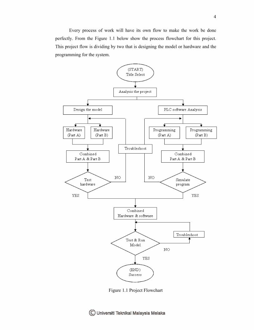
Every process of work will have its own flow to make the work be done
perfectly. From the Figure 1.1 below show the process flowchart for this project.
This project flow is dividing by two that is designing the model or hardware and the
programming for the system.
Figure 1.1 Project Flowchart
5
1.6 Thesis Outline
This thesis describes the auto level parking model. In this thesis, it consists of
five chapters. A brief introduction about the project including the objectives, problem
statement and scope of the project will be explained in chapter 1. A literature review
of recent work on the auto level parking model theory and the application that is
related to this project is presented in chapter 2. Chapter 3 gives a detailed
description of each component that is used in the project and how each of the
components can be used in the project. All the analysis and result regarding to the
project will be presented in chapter 4. And finally, chapter 5 will be summarizes the
contributions of this work along with suggesting avenue for future explorations.
CHAPTER II
LITERATURE REVIEW
This chapter presents all the literature review and some research requiring based
on the auto level parking system. This literature review is primarily restricted to
published research results on elevator system and automated multistoried car parking
system. This literature review is required to study all the characteristic and their
algorithm, requirement needed, and general idea of this project. All the information that
has been collected is very important to ensure that this project achieved their objectives.
2.1 Control Of A Four-Level Elevator System Using A Programmable Logic
Controller
This project focuses on the design and implementation of a PLC-based
controller for a four level elevator. The PLC used is an Omron Sysmac C20K with
12 inputs and 8 outputs. The design incorporates an intelligent controller that
services all the requests in an energy-saving way, rather than on a first-come, first-
served basis.
7
2.1.1 Hardware Design
The objective of the hardware design is to develop the interface circuit
between the PLC and the elevator system and the elevator control panel, with both
external and internal requests. These requests are produced by push buttons that send
continuous signals to the PLC when activated. Each push button is connected to an
LED to identify the request placed. In addition, the four floors are represented by
four LEDs, one for each level. Furthermore, an alarm switch is installed to produce a
flashing signal whenever activated.
This facility was introduced to simulate the desire for a sudden stoppage of
the elevator either for reasons of safety or for requests for a repair job to be carried
out on the elevator. In order to obtain the desired setup, we needed to find a way to
capture the pulse generated by a depressed push button. We also needed to make sure
that the PLC is recognizing these signals in order for it to correctly perform the
required action. As explained below, both issues were resolved by using set/reset flip
flops and relays respectively.
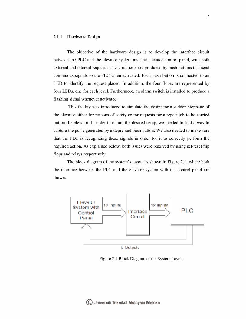
The block diagram of the system’s layout is shown in Figure 2.1, where both
the interface between the PLC and the elevator system with the control panel are
drawn.
Figure 2.1 Block Diagram of the System Layout
8
2.1.2 Description Of The Interface Circuit
The hardware components used in the project is Omron Sysmac C20K PLC,
74LS04, 74LS279, 74LS156, which are inverters, SR flip flops and buffers,
respectively. Also used voltage supply, push buttons, LED, resistors, relays, a switch,
and connecting wires. Since the number of required inputs and outputs, i.e. 12 and 8
respectively, matches the maximum input/output capability of the PLC used, there is
no need for any multiplexing or demultiplexing operations. Thus all inputs and
outputs used can indirectly controlled by the PLC.
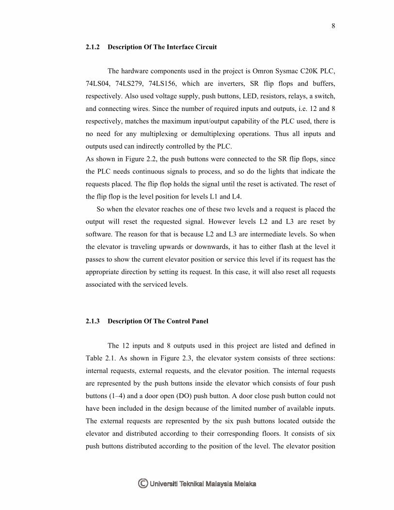
As shown in Figure 2.2, the push buttons were connected to the SR flip flops, since
the PLC needs continuous signals to process, and so do the lights that indicate the
requests placed. The flip flop holds the signal until the reset is activated. The reset of
the flip flop is the level position for levels L1 and L4.
So when the elevator reaches one of these two levels and a request is placed the
output will reset the requested signal. However levels L2 and L3 are reset by
software. The reason for that is because L2 and L3 are intermediate levels. So when
the elevator is traveling upwards or downwards, it has to either flash at the level it
passes to show the current elevator position or service this level if its request has the
appropriate direction by setting its request. In this case, it will also reset all requests
associated with the serviced levels.
2.1.3 Description Of The Control Panel
The 12 inputs and 8 outputs used in this project are listed and defined in
Table 2.1. As shown in Figure 2.3, the elevator system consists of three sections:
internal requests, external requests, and the elevator position. The internal requests
are represented by the push buttons inside the elevator which consists of four push
buttons (1–4) and a door open (DO) push button. A door close push button could not
have been included in the design because of the limited number of available inputs.
The external requests are represented by the six push buttons located outside the
elevator and distributed according to their corresponding floors. It consists of six
push buttons distributed according to the position of the level. The elevator position
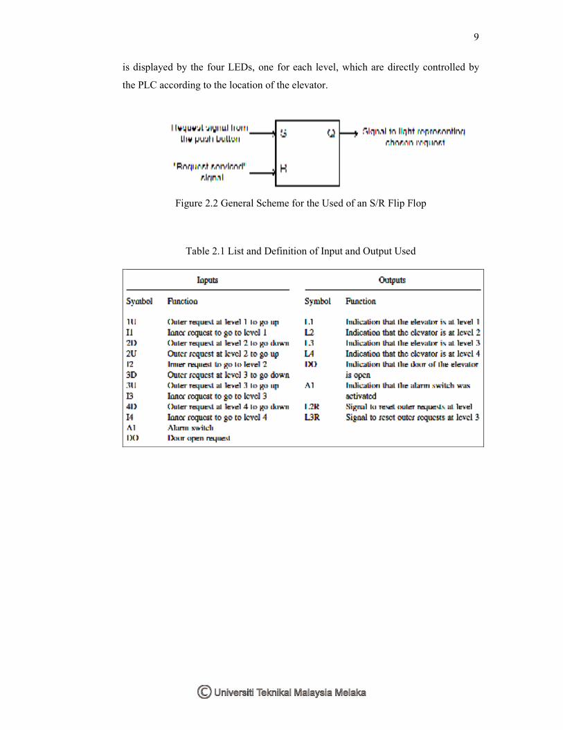
9
is displayed by the four LEDs, one for each level, which are directly controlled by
the PLC according to the location of the elevator.
Figure 2.2 General Scheme for the Used of an S/R Flip Flop
Table 2.1 List and Definition of Input and Output Used