Embed Size (px)
Citation preview
�ŭŨĸǮ�ĒĉİÌĨĨĒİĉ�SEPD�
&óîĒèÌŨóî�,įçóîîóî��ƉŠŨóįŠ�
BKN�@ÌŠŨóŚ�&óŗĨĸƉįóİŨ�ȯ�
�ƂÌĒĨÌçĒĨĒŨƉ
$�ZHE�SUHVHQWDWLRQ�
6KUL�6DPEL�5HGG\�%��&KLHI�(QJLQHHU���())7521,&6
7XHVGD\�$XJXVW���������������$0
Oekh�>eij,5,6(7

�ďŚĒ��ǝ��ÌįçĒ��óîîƉ ďĒóĈ�,İĉĒİóóŚǘ�,ĈĈŨŚĸİĒèŠ��ƉŠŨóįŠƔ %�7HFK�IURP�5(&�:DUDQJDO�
Ɣ ,566(������EDWFK�
Ɣ 5HWLUHG�YROXQWDULO\�LQ������ZKLOH�ZRUNLQJ�DV�&67(�&1�(&25�
Ɣ :RUNHG�IRU�����\HDUV�DV�FRQVXOWDQW�WR�$QVDOGR�IRU�.):�SURMHFW
Ɣ /DVW����\HDUV�ZRUNLQJ�DV�&KLHI�(QJLQHHU�ZLWK�(IIWURQLFV���GHYHORSLQJ�6,/���SURGXFWV�DQG�VLJQDOOLQJ�V\VWHP�+HDOWK�0RQLWRULQJ�6\VWHPV
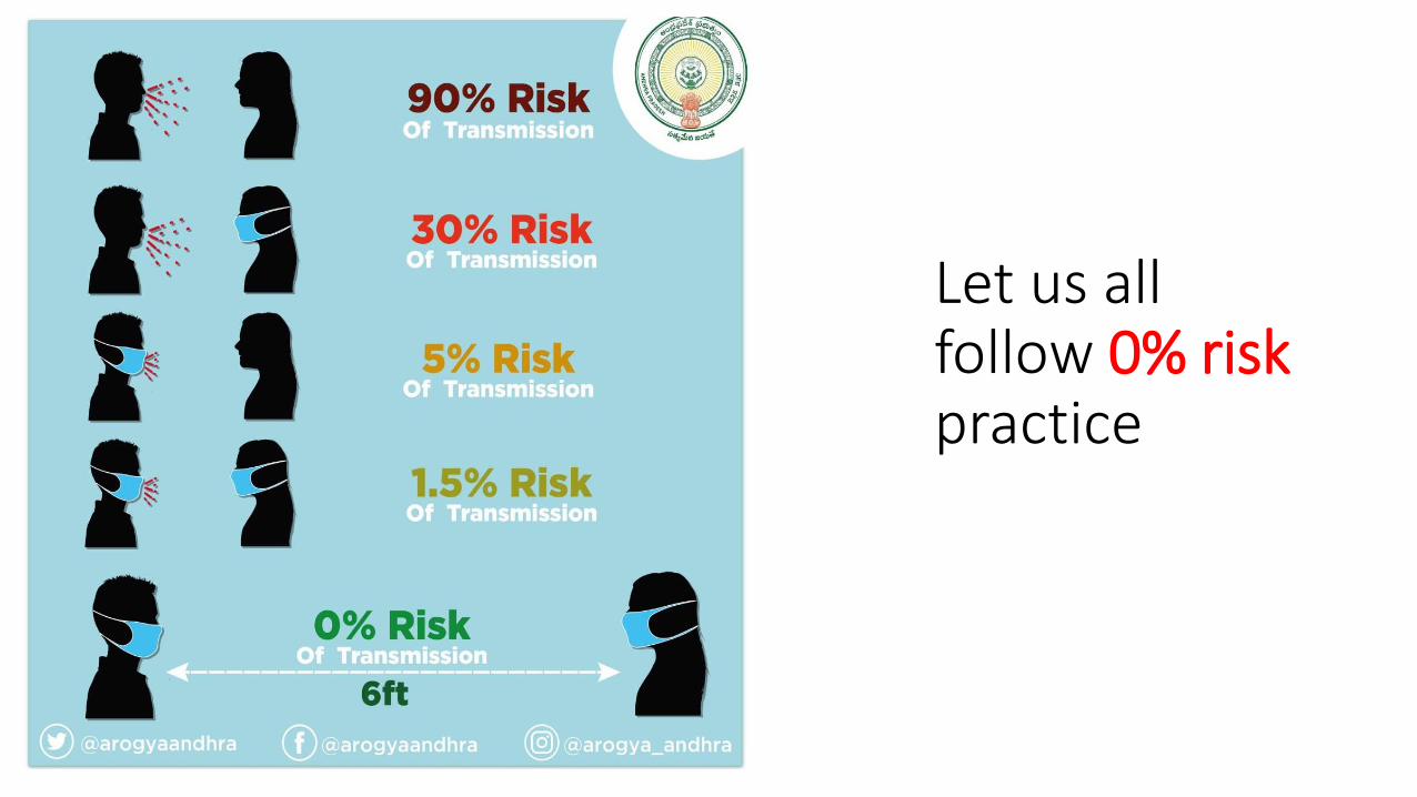
Let us all follow 0% risk practice

3 Areas of contact – how to avoid ?

Contents
1. Present system of auto signalling 2. Limitations of present system 3. Proposed system 4. A better construction practice for wayside station5. A brief introduction to EULYNX

Challenge faced by S&T
• Line capacity enhancement by auto-signaling is top priority work by S&T department today
• Projects are delayed due to design, installation, testing & commissioningprocesses because of usage of relays and copper cable
• Maintenance of newly created auto signaling assets imposes heavy stress on maintenance organization due to large quantity of copper cable, relays distributed all along the track which cannot be provided with redundancy

Auto signallingwith
Relay Interlocking
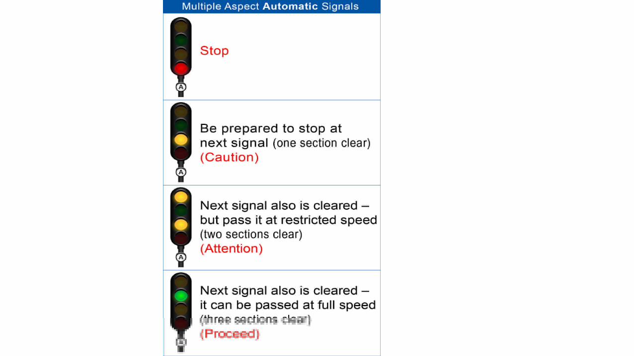

Automatic signalling system
• 4 aspect signals • Inter-signal distance is about 1 km [Emergency Braking Distance] • Continuous train detection system• Semi-automatic signals for mainline at the station & at level crossing gate


Controlling of auto signal
Relays required at each auto location – A2 signal 1. A2 - A3 Auto section & overlap train detection relays – 2TPR, 2ATPR & 3TPR 2. 4 ECPRs of A3 signal - A3 RECPR, A3 HECPR, A3 HHECPR & A3 DECPR3. 4 ECRs of A2 signal - A2 RECR, A2 HECR, A2 HHECR & A2 DECR4. 4 ECPRs of A2 signal - A2 RECPR, A2 HECPR, A2 HHECPR & A2 DECPR5. 3 control relays of A2 signal - A2 HR, A2 HHR & A2 DR – Total relays – 18 Cables required 1. A2 to A3 – 8 conductors for ECRs, 2 conductors for 3TPR [overlap track]2. 230 /110 V AC busbar
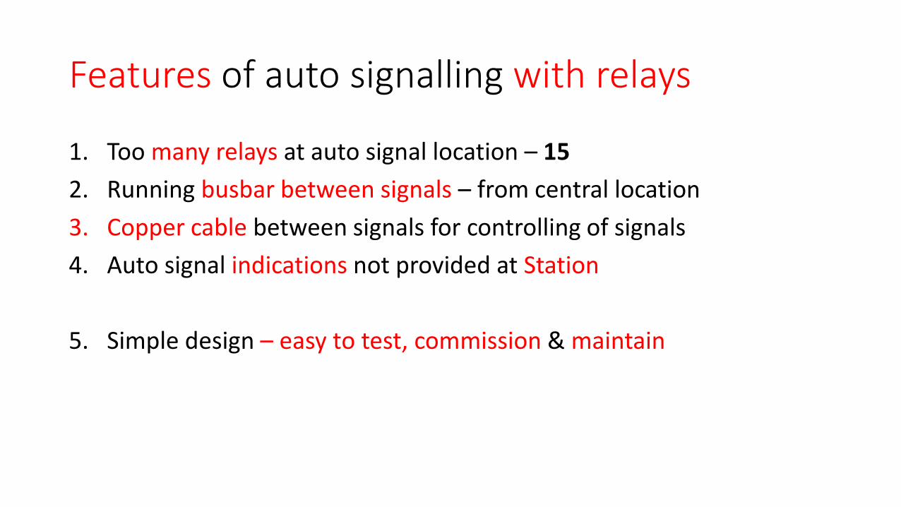
Features of auto signalling with relays
1. Too many relays at auto signal location – 15 2. Running busbar between signals – from central location 3. Copper cable between signals for controlling of signals 4. Auto signal indications not provided at Station
5. Simple design – easy to test, commission & maintain

Auto section status to SM by data logger system – SER, SECR, ECOR, NR


Auto signalling with EI

Auto signalling with EI – Processors deployment

Auto signalling with EI – signal lighting from ALH [Auto Location Hut] with copper cable

Auto signalling with EI – Train detection by MSDAC
• Two MSDAC systems are provided one for each – Up & down line• Supervisory monitoring of UP line is done by Down System & vice-versa• Two inputs to I/O gatherer [clear, preparatory reset] and one output from I/O
gatherer [reset command]

Power supply requirements 1. 110 V AC for lighting of signals 2. 24 VDC for MSDAC3. 24 VDC for External relays 4. 24 V DC for EI I/O gatherer 5. Integrated Power Supply – IPS with 110 V DC battery back up is provided
6. Primary source of supply: AT supply at alternate ALH – supply extended to adjacent ALH

Features of Auto signalling with EI
1. Since EI is used – both FAT & SAT are to be carried out 2. Relays are used – reduced compared to relay interlocking 3. Increase of copper cable used 4. Busbar cable when AT is not provided due to distance limitation
5. Signal lamp cascading implementation by software 6. Signal lamp control relay logic implementation by software 7. Display of auto signals status to station

Understanding of embeddedequipment

What is embedded system
• An embedded system is a microprocessor - or microcontroller -based system of hardware and software designed to perform dedicated functions within a larger mechanical / electrical system
• It has software embedded into hardware (also known as Firmware) to perform specific tasks or a single task

Vital & Non-vital ports
1. Data exchange through vital ports ensures fail-safe
2. Data exchange through non-vital ports is not fail-safe

Parallel & Series interfaces
1. Parallel interface – is wiring thepotential free contacts of outputs ofone equipment as input to other
2. Serial data interface requires higherlevel of integration of products – datatransfer by changing the data protocols
3. Serial interface requires less hardware

Object controller – driven by EI
1. Signal lamp – directly driven byhardware – without relay – lampchecking done by hardware – withoutlamp checking relay
2. Point machine – directly driven byhardware – without relay – detectiondone by detecting closing of detectioncontacts

EI – General purpose embedded system ASC - Dedicated embedded system
1. EI has both Executive software & Application software2. Embedded equipment has one software only – loaded in factory – can not be altered at
site

Auto signalling with embedded equipment
Auto Signal Controllers – ASCs

Auto signalling with ASCs - Dedicated embedded controller

Auto signalling with EI – Processors deployment

4 Types of ASCs
Auto section 1. ASC – auto signal – drives 4 lamps 2. ASC – semi-auto signal at LC gate – drives 5 lamps
Station interface 1. ASC – train receiving end – repeats home aspects to last auto signal 2. ASC – train sending end – repeats first auto signal aspects to station

ASC –AutoSignalController

ASC – replaces interlocking & interface

Output card of ASC directly lights signal lamp & detects lamp lighting current -
HR, HHR, DR & RECR, HECR, DECR & HHECR relays NOT required
ACRR1 & ACRR2 –Axle counter reset relays

ACRR1 & ACRR2 –Axle counter reset relaysLCAWR – Level crossing approach warning relayLCFR – Level crossing approach locking relay
Station interface to Auto signalling
Two types of Station ASCs

Interface with station interlocking – Dispatching trains


Interface with station interlocking – Receiving trains


MMI - Man Machine Interface – at station

MMI - Man Machine Interface – at station
SM interface • To see the status of signalling system • To keep the auto signal at ON • To reset axle counter
Maintenance interface • To see the status of signalling system• To see diagnostic data


Interface with level crossing gates
• Approach warning – driver shall see gate approach signals, less than proceed aspect
• Approach locking – it shall not be possible to open the gate when the train is on approach track
• Gate status

MSDAC or HA SSDAC


Features of HA SSDAC & MSDAC HA SSDAC 1. Impact of failure is limited to one section 2. Copper cable can be totally eliminated by OFC 3. Poor diagnostics – high level skills required for maintenance MSDAC 1. Matured technology 2. High level diagnostics – enables predictive maintenance 3. Large amount of copper cable usage – more maintenance, less reliable4. Common mode failure impact is severe on the system availability

Monitoring health of various equipment


Power requirement 1. Auto Signal Controller – 25 W 2. Signal Lamps – 20 W 3. Axle counter – 80 W 4. HMU – 25 W 5. Switch – 25 W 6. TOTAL = 175 W

Auto signals at less than BD

ASC – at Auto signal at less than BD

Signal lamp – 110 V AC or 24 V DC 110 V AC Lamp features 1. Proven product 2. Affected by induced voltages of AC electrified traction 3. More electronics – less reliable [AC to DC conversion required]
24 V DC Lamp features 1. Power consumption can be reduced to almost half 2. Least affected by induced voltages of AC electrified traction 3. Less electronics – more reliable [AC to DC conversion not required]4. New product – initial reliability issues

Processors – SIL 4 general purpose PLC vs. customised
SIL 4 general purpose1. Hardware easy availability 2. Proven reliability 3. May cost more
Customised1. Cost under control of OEM 2. Tied up to the OEM for spares

Testing – SAT Automation

Site Acceptance Test – signals Aspect sequence test 1. Each signal lamp supply is cut off – remotely by test system 2. Response of the signal and signals in the approach is recorded by
HMUs3. The response is compared with the TOC – automatically Signal control test 1. Train detection system is remotely controlled by test system – train
occupied / vacated conditions 2. Response of the signal and signals in the approach is recorded by
HMUs3. The response is compared with the TOC – automatically

Site Acceptance Test – LC gate Approach warning test 1. Drop the train detection – sequentially – record the status of approach
warning relay at the gate controller 2. The response is compared with the TOC – automatically Approach locking test 1. Drop the train detection – sequentially – record the status of approach
locking relay at the gate controller 2. The response is compared with the TOC – automatically

RD – miniature Relay Driver 1. Their contacts are
wired temporarily in the feed of the signal lamp & DAC input
2. Miniature relays are controlled by test software
3. Test results are compared automatically to provide test result

Features of ASC
1. Reading potential free contacts 2. Vital data exchange with adjacent ASCs3. Driving signal lamps 4. Detecting lamp current – ECR functionality 5. Driving relays 6. Port to provide diagnostic data 7. Data exchange with DAC [optional]

System availability Redundancy & Predictability

FMA – Failure Mode Analysis 1. OFC – media diversity with path diversity 2. Power supply – source diversity with path diversity3. Auto Signal Controller – 2oo3 architecture 4. Auto Signal controller – failure affects one direction traffic only & a
maximum of two sections are affected 5. HMUs – to provide extensive diagnostics of processor based systems
[DAC, ASC & PSU] and communication media

Merits of Proposed system 1. Copper cable required per signal is less than 50 meters2. Block section of 12 KM may hardly require 1 KM of signaling cable3. No relays – except for LC gate4. No signal specific interlocking design required as each signal design is
embedded in the controller [ensure BD – between two signals]5. Design, testing, commissioning & maintenance efforts reduced 6. Integrated predictive maintenance through extensive health monitoring
system
Limitation • If inter-signal distance is less special design to be done

A case of train detection system
unsafe failure


Conclusions1. Auto signaling through processor based dedicated embedded controllers
networked through OFC reduces auto signaling project’s cycle time 2. Extensive diagnostics provided by the processor based embedded
equipment with redundancy ensures availability of signaling system3. The networked diagnostic system which supports predictive
maintenance reduces maintenance effort – present maintainers with little reorientation can maintain new assets created
4. IR to develop specifications with active collaboration of industry to fast track auto-signaling projects

EULYNX The next generation signalling strategy for Europe

ERTMS – European Rail Traffic Management System – purpose
1. ERTMS - Industrial project developed by 8 UNIEF members – Alstom, Ansaldo, AZD Praha, Bombardier, CAF, Mermec, Thales & SIEMENS in close cooperation with EU, Railway managements & GSM-R industry
2. ERTMS User Group – EUG: To help railway companies in applying ERTMS / ETCS – in a harmonised & interoperable way – to enable free movement of trains and a competitive railway
3. ERTMS – formed in 1989 – took more than 25 years to meet the initial requirements of EU railways

FFFIS – Form Fit Function Interface Spec – defines Level of interoperability of each sub-system

EULYNX • Initiative by 13 infrastructure managers to standardize interfaces &
signalling elements of signalling system
• To reduce lifecycle cost of systems • Digitisation – leading to continuous monitoring & condition based
maintenance
• Initiated in 2014 – First phase – framing specifications – completed • Base line 3 – issued in 2020 – manufacturers can start development work

EULYNX
1. When Harmonising interlocking part of CCS - INESS project to develop common Euro interlocking – failed
2. A new approach is adopted – i.e. reduction of lifecycle cost by interchangeability of components – adopted
3. Under the umbrella of EULYNX – a set of interface specs are framed for track side parts

Semi centralisation of outdoor gears at
wayside station
Improved quality of installation, Maintainability, Monitorability


Drawbacks of the system
1. Large number of foundations – in the field – difficult to ensure quality2. Quality of wiring and soldering – affected 3. Access to gears is poor 4. Limited space – many a time location box can be opened on one side only 5. Poor Ingress Protection of location box – affects the life of gears 6. Ensuring SOD – Schedule Of Dimensions7. Difficult to monitor health of assets

Advantages of limited centralisation 1. Sufficient space for erecting the equipment2. Troubleshooting comfortable 3. Easy to monitor equipment
4. Busbar lengths reduced – less impact of EMI 5. Track side location box converted to cable termination box – its height
can be limited to one foot above rail level 6. Temperature rise is limited due to more space

Thanks