Embed Size (px)
Citation preview

USER GUIDE

Safety InformationBefore using this equipment, carefully read, understand and follow instructions and safety messages on equipment and in this guide.
This guide cannot anticipate or provide advice and cautions for all situations encountered by technicians. With this in mind, always follow and refer to the manuals provided by the manufacturer of the vehicle or equipment being tested or used for all information and testing procedures whenever diagnosing, repairing or operating such vehicle or equipment.
Failure to follow the instructions, cautions and warnings provided here as well as those provided by the vehicle and equipment manufacturers can result in fire, explosion, bodily injury and property damage.
In addition to the information listed below, additional warnings and cautions are listed throughout the guide. Please read them carefully.
Fuel vapors are toxic and explosive, which can cause severe injury or death.• Useproperventilationtoavoidbreathingfuelvapors.
• Minimizecontactwiththeskinwiththeuseofgloves(suchasnitrilegloves)whenthereispossibility of getting methanol fuel on your hands.
• Iftheskinisdirectlyexposed,washtheareaimmediatelyandchangeanyclothesthathavebecome wet with fuel.
• Alwayswearapprovedsafetyglasseswhentesting.Shouldfuelgetintoeyes,flusheyesimmediately with water and consult your physician.
Vehicles emit flammable vapors which can ignite.• Keepflames,sparks,cigarettesandotherignitionsourcesawayfromthevehicleatalltimes.
• Incaseoffire,neverusewatertofightflamescausedbymethanolormethanolblendedgasoline.Thiswillcausetheflamestospreadinsteadofextinguishingthem.
• Useadrychemicalextinguishertofightflames(preferablyonemarkedABC,thoughBCisacceptable).AfoamextinguisherisacceptableonlyifitisARFgrade,whichisresistanttoalcohol.
Before beginning any tests, make sure the test environment is safe and the vehicle meets these conditions:• Testareashouldbewellventilated.
• Vehicleshouldbeinpark.
• Wheelsshouldbeblocked.
• Engineshouldbeatnormaloperatingtemperature.
• Vehicleshouldhavenormalexhaustflow.
• Keepalltestercablesclearofexhaustmanifoldsandradiatorfanblades.
• Usecautionwhentestingonavehiclewhiletheengineisrunning(surfacesmaybecomehot,electriccoolingfansmayturnonunexpectedly,etc.)
©2014HickokInc.Allrightsreserved.
Allrightsreserved.
No part of this manual may be reproduced or transmitted in any form or by any means, electronic or mechanical,withoutwrittenpermissionfromHickok.
Hickokassumesnoresponsibilityforuseofthisequipmentbyuntrainedorunauthorizedpersons.
PrintedintheUnitedStatesofAmerica.

3
Contents
Components .....................................................................................5AutoWave ................................................................................................................................................... 5
SignalProbe ................................................................................................................................................. 5
ExtenderCable ........................................................................................................................................... 5
GroundCable .............................................................................................................................................. 5
SDCardAdapter......................................................................................................................................... 5
Controls and Connections ...............................................................6FrontView .........................................................................................................................6
On-Off/MenuButton .............................................................................................................................. 6
Help / Headlights Button ........................................................................................................................ 6
SelectButton ............................................................................................................................................... 7
Navigation Buttons ................................................................................................................................... 7
BackView ...........................................................................................................................8LCDScreenSymbolsandIndicators ........................................................................8
Setup Procedure ..............................................................................9WithouttheExtenderCable .......................................................................................9WiththeExtenderCable ..............................................................................................9WhyGroundHookupIsImportant ..........................................................................9
How To… ........................................................................................10ViewaLiveWaveform ................................................................................................ 10PanorZoomWhileViewingLiveorSavedWaveform .................................... 10CaptureandSaveaWaveform .......................................................................................................10CreateBitmaps ............................................................................................................. 11ViewSavedWaveforms ................................................................................................. 11RemovetheMicroSDCard ...................................................................................... 12ReplacetheBattery ...............................................................................................................12
Main Menu Functions ....................................................................13MainMenu ..................................................................................................................... 13Auto-Set .......................................................................................................................... 13LiveCamera ................................................................................................................... 13

4
Contents
Live Trending ................................................................................................................. 14VoltMeter ....................................................................................................................... 14File List ............................................................................................................................. 15Browse Waves ............................................................................................................... 15BatteryStatus ................................................................................................................ 15DelayedCapture .......................................................................................................... 16Trigger ............................................................................................................................. 16
Example Waveforms ......................................................................18
Technical Information ...................................................................19TimeScales .................................................................................................................... 19VoltageScales .............................................................................................................. 21
Specifications .................................................................................22
Contact Information ......................................................................23
Warranty .........................................................................................24

5
Components
Auto Wave
Usedalongwiththesuppliedcablesandsignalprobe,allowsyoutoviewwaveforms for analysis and pinpoint diagnostics.
Signal Probe
Usedfortestingsignalsandvoltages.Thesignalprobecanbeconvenientlystoredinthegroundjackportlocatedonthebackofthehandle.
Extender Cable
The 3-Ft. Extender Cable (with the signal probe attached) is used when a longer reach is required.
Ground Cable
The5-Ft.GroundCableisusedtosafelygroundthetestertothevehicle.Note: A good ground connection is required for obtaining clean waveforms.
SD Card Adapter
Usedwiththe4GBSDcardtodownloadandviewsavedbitmaps
MENU HELP
Lock
Adapter
4GB
ExtenderCable
4GBSDCardandAdapter
GroundCable
SignalProbe
AutoWave

6
Controls and Connections
Front View
MENU HELP
Help / HeadlampOn-Off/Menu
Navigation Buttons (up,down,left,right)
LCDScreen
SelectButton
On-Off / Menu Button
TopoweronAutoWave—pressandreleasetheOn-Off/Menubutton.
• AutoWavealwayspowersupintheLiveTrendingmodesetat200mSand 2v scales.
ToaccesstheMainMenu—pressandreleasetheOn-Off/Menubutton.
• PressandreleasetheMenubuttonagaintoreturntothecurrentoperation.
TopoweroffAutoWave—pressandholdtheOn-Off/Menubutton.
• AutoWaveautomaticallyturnsoffafter2-minutesofnoactivity.
Help / Headlights Button
Todisplayhelponthecurrentoperation—pressandreleasetheHelp/Headlamp button at any time.
• ContinuetopressandreleasetheHelpbuttontoscrollthroughthepages(ifthereismorethanone)andtoreturntothecurrentoperation.
Toturntheheadlampon—pressandholdtheHelp/Headlampbutton.
• Pressandreleasethebuttonagaintoturntheheadlampoff.

7
Controls and Connections
Select Button
The function of this button varies depending on use and the mode of operation you are currently in.
Press and release to:
• SelectMainMenuitems.
• ToswitchbetweenPANandZOOMduringLiveTrending/Camerafunctions.
Press and hold to:
• Captureandsavethecurrentlydisplayedwave.
• Displayalistofoptions(Resume,Bitmap,Cancel,Delete)whileviewingsaved waveforms.
Navigation Buttons
The function of this button varies depending on the mode of operation you are currently in.
Up,Down,Left,Rightbuttonsareusedto:
• NavigateMainMenuitems.
• Adjusttimeandvoltagescaleswhenviewingliveorsaved waveforms(ZOOM).
• Movewaveformleft,right,upordownwhenviewingliveorsavedwaveforms(PAN).
• TogglethroughFileListandBrowseWavesmenuitems.
• Clearmin,maxvaluesinVoltmetermode.
• AdjustAutoTriggerandManualTriggersettings.
SeeMain Menu and How To sections for more detail

8
Controls and Connections
LCD Screen Symbols and Indicators
PAN T= 500 uSV= 10V
Active PAN/ZOOMView
(blue)
Trigger Point Indicator (purple)
Trigger Level Indicator (purple)
TimeDivisions (yellow)
Live Wave (green)
VoltageDivisions (red)
ZeroVoltsMark (gray)
TimeScale (Yellow)
VoltageScale (red)
++
www.hickok-inc.com
Made in USA
ExtenderCable&SignalProbeJack
4GBMicroSDCardSlot
GroundJack&SignalProbeStorage 9VBatteryCompartment
LEDHeadlamps
Back View

9
Setup Procedure
Without the Extender Cable• PlugtheSignalProbedirectlyintothesignalprobe
inputjack
• Plugthe ground cable into the ground jack.
With the Extender Cable• PlugtheExtenderCabledirectlyintothesignal
probeinputjack
• PlugtheSignalProbeintothefemaleendoftheextender cable.
• Plugthegroundcableintothegroundjack.
Note: When using the Extender Cable, make sure to keep it away from high noise sources to prevent noise from coupling into the wire and affecting the signal being viewed.
Why Ground Hookup Is Important• Connectingagoodgroundpointisimportantfor
obtaining clean waveforms.
• For most vehicle signals, the battery negative terminal or the engine blockwillprovideacleanground.
• Abadground,suchasthevehiclechassis,mayaddfalsenoise to the signal.
ThesameO2sensorsignalwiththeGroundCableconnectedintwodifferentplaces:
WAVE0570 V= 500mVT= 400 mS
WAVE0571 V= 500mVT= 400 mS
Good Ground Bad Ground
++
www.hickok-inc.com
Made in USA
++
www.hickok-inc.com
Made in USA
++
www.hickok-inc.com
Made in USA
++
www.hickok-inc.com
Made in USA

10
How To…
View a Live WaveformBasicoverviewonhowtouseAutoWave.
• Determinethesetupyourequire(with/withoutextendercable)andconnect the ground cable to a good ground on the vehicle.
• TurnAutoWaveonandprobethedesiredelectricalsignalorvoltageonthevehicle.AwaveformshouldappearontheLCDscreenindicatingthepresence of a signal.
• Ifneeded,gototheMainMenuandselectafunctiontoadjusthowyouacquireandviewthesignal(SeeMain Menusectionformoredetails).
Pan or Zoom While Viewing Live or Saved WaveformPress and release the navigation buttons to Pan or Zoom the screen view.
Zoom• Leftbuttondecreases(Zoomin)thetimesetting(T=)• Rightbuttonincreases(Zoomout)thetimesetting(T=)• Upbuttondecreases(ZoomIn)thevoltagesetting(V=)• Downbuttonincreases(Zoomout)thevoltagesetting(V=)
Pan• UsetheNavigationbuttonstomovethescreenviewinthedesireddirection.
Note: The time and voltage scale setting used during live waveform viewing sets the sample rate and the saved waveforms length.
Capture and Save a WaveformAwaveformcanbecapturedandsavedforfurtherreview.
•Whileviewingalivewaveform,pressandholdtheSelectbuttontocaptureandsaveit.
•Ayellowboxappearsaroundthewaveformanddisplaystheassignedfilename(i.e.WAVE0025).
• ToviewsavedwaveformsonaPCtheywillneedtobesavedasaBitmapfile(SeeCreate Bitmaps).
•Toreturntolivewaveformviewing,pressandholdSelectuntilthedialogboxappearsandthenselectRESUME.
Note: A saved waveform’s resolution is determined by the Time and Voltage settings at the time a waveform is captured and cannot be adjusted once saved.
Saving...WAVE0025
T= 500 uSV= 10V
ZOOM

11
How To…
Create Bitmaps
Whileviewingsavedwaves,createacustomizedbitmaptoshowtheattributesofacapturedwaveformforviewingonaPC.
• PositionthewaveformusingPAN/ZOOM,thenholddowntheSelectbuttonuntilthe File Option list appears.
•SelectBITMAPandwaitfortheprocessto complete and return to the saved waveform view.
• AdjustingthePAN/ZOOMandresavingthe file will overwrite the previous bitmap.
Note: Once saved, the bitmap retains the same filename except with a .BMP extension.
View Saved WaveformsAccessandviewsavedwaveformsonAutoWavethroughtheMainMenuoptions,onyourPC,orimmediatelyaftersavingawaveform.
Saved waveform file options
PressandholdtheSelectbuttontoviewthefileoptions.• Resume—Returnstothepreviouslivesettings• Bitmap—Createsandsavesafileasabitmap(requiredforviewingonaPC)• Cancel—Exitfileoptionlist(noaction)• Delete—Deletesthecurrentsavedwaveform(cannotbeundone).• PressandreleasetheSelectbuttontochoosedesiredoption.
Viewing saved waveforms
ChoosethewaveformtobeviewedandpressSelect.• Voltageandtimesettingsareshownastheyappearedwhenthe
waveform was saved.
• PanandZoomfunctionscanbeusedtogetamoredetailedviewof the waveform.
• ToviewadditionalwaveformspressandreleasetheMenubuttontobereturnedtothelastMainMenuitemselected.
• Toexitviewingsavedwaveforms,pressandholdtheSelectbutton.SelectingRESUMEwilltakeyoubacktothelivewaveformviewingscreen.
RESUMEBITMAPCANCELDELETE
ZOOM T= 1 mSV= 5VWAVE0374

12
How To…
Viewing waveforms saved as Bitmaps on a PC
• RemovetheMicroSDCardfromthetopofAutoWaveandinsertitintotheprovidedSDCardAdapter
• InserttheadapterintotheSDCardreaderonyourPC.
• OpentheassociateddiskdriveandfolderrelatedtotheSDCard.
• FilessavedasBitmapswillhavethe.BMPfileextension(ie.WAVE001.BMP).
IMPORTANT! It is recommended to only delete the WAVEFILE.DAT file if the card becomes corrupted or files are missing. Deleting this file forces the unit to scan all files and rebuild the missing or corrupted files.
Remove the Micro SD Card
ThecardmayberemovedandinstalledonaPCtoviewsavedbitmaps.
•TurnoffAutoWaveandremovetheSDCardslotcoveronthetopof the unit.
•Pushthecarddownuntilitclicksandreleases.
• Re-insertthecard,withtheprintedsurfacefacingthebackoftheunit.Makesuretore-insertthecoveronthetopoftheunit.
Replace the BatteryAutoWaveusesa9VAlkalinebatterylocatedinthebottomofthehandle.
• HoldunitwithLCDscreenfacing down and remove bottom plug.
• Liftthebatteryofftheretainerledge and slide battery out.
•Locatetheplus(+)symbolinfront of the retainer ledge and install the new battery with the +sidetotheright.
•Pushdowntosnapthebatteryin behind the retainer ledge.
• Re-insertthebottomplug.
Snapbatteryinbehindthe retainer ledge

13
Main Menu Functions
Main MenuTheMainMenuisavailableataytimebypressingandreleasingtheMenubutton.
•UsetheUp/DownNavigationbuttonsto scroll through the menu.
•PressandreleasetheSelectbuttontoselect or change the item.
•PressandreleasetheMenubuttonagain to return to the previous mode.
Auto-SetPerforms automatic time and voltage scales adjustment.
•Connectsignalprobetodesiredsignalor voltage.
• GototheMainMenuandselect Auto-Set.
• Duringtheprocessthepercentprogressis displayed on the lower right corner of theLCD.
•MakesuretokeeptheSignalProbeincontact with the signal until it completes.
• PressandreleaseSelectatanytimetoaborttheprocessleavingAutoWave at the current settings.
Live CameraUseLiveCameraviewingforhighfrequencysignalsorforrevealingdetailsin slower signals.
• Timesettingsrangingfrom 50mS/Div.to100uS/Div.useasnapshot method for wave viewing.
• Dataissampledthendisplayedasaseries of still snapshots according to the current trigger settings.
Note: To optimize intermittent signal analysis use the Live Trending setting
MAIN MENU
LIVE CAMERAAUTO-SET
LIVE TRENDINGVOLT METERFILE LISTBROWSE WAVESBATTERY STATUSDELAYED CAPTURETRIGGER AUTO 50% RISE
PAN T= 500 uSV= 10V
ZOOM T= 20 uSV= 2V
60%

14
Main Menu Functions
Live TrendingUseLiveTrendingforwatchingslowvoltagechangesorforcapturingintermittent dropouts on faster signals.
•Timesettingsbetween100mS/Div.upto20Sec/Div.dataaredisplayedsimultaneously so voltage changes appearinrealtimeontheLCDtrendingfrom right to left.
Note: A saved waveform’s resolution is determined by the Time and Voltage settings at the time a waveform is captured and cannot be adjusted once saved.
Volt MeterProvides basic auto-ranging digital volt meter functionality.
• Voltreadingsareupdated40/sec.
• Thecurrentvoltagereadingisdisplayed in the Now box.
• MaxandMinboxesrepresentthehighest and lowest voltages seen in the Now box.
•TocleartheMaxvalue,pressandreleasetheUpbutton.
•TocleartheMinvalue,pressandreleasetheDownbutton.
•Toclearboth,pressandreleasetheSelectbutton.
Note: For very low millivolt measurements zero the volt meter and leads by connecting (short) the ground lead to the probe tip, press and hold the Select button until the digits read 0.000 then release the Select button.
MAIN MENU
LIVE CAMERAAUTO-SET
LIVE TRENDINGVOLT METERFILE LISTBROWSE WAVESBATTERY STATUSDELAYED CAPTURETRIGGER AUTO 50% RISE
VOLT METER
+10.80
+13.40
+ 07.2
NOW
MAX
MIN
VDC
VDC
VDC

15
Main Menu Functions
File ListDisplaysalistofthewaveformfilescurrentlystoredontheSDcard.
• Use the up/down navigation buttons to scroll through the list one file at a time or use the left/right buttons to scroll by page.
• PressandreleaseSelecttoloadthefilefor viewing.
• PressandholdtheSelectbuttontodisplayalistofoptions(seeFileOptions).
• ThetotalfilesontheSDcardisshownatthebottomofthelist.
Browse WavesDisplaysagraphicalpreviewofeachwaveinlightblue.
•UsetheNavigationbuttonstopreviewthe saved waveforms.
• PressandreleaseSelecttoloadthefilefor viewing.
•PressandholdtheSelectbuttontodisplayalistofoptions(seeFile Options).
Battery StatusDisplaysthecurrentbatterychargelevelinpercentandshowsbatteryvoltage.
• AutoWaveneeds6Vormoretooperate. When the percentage charge reaches 0% the battery needs to be replaced.
SAVED WAVE FILE LIST
WAVE0349WAVE0350WAVE0351WAVE0352WAVE0353
WAVE0355WAVE0354
WAVE0356
TOTAL SAVED = 362
WAVE0376.txt
BATTERY CHARGE
8.66V
88%

16
Main Menu Functions
Delayed CaptureSetsa10secondtimertoautomaticallycapturethewaveform.
•Whenviewingalivewaveformmakeany necessary adjustments to the time/voltage scales and triggering.
•GototheMainMenuandselectDelayedCapture.
•AlargecountdownnumberappearsintheupperlefthandcorneroftheLCDscreen showing the seconds remaining (startsat10sec.).
•With1sec.remainingtheLEDheadlightswillturnon.
•Whenthecountdownreacheszerothewaveformiscaptured,savedandtheLEDHeadlightsturnoff.
TriggerUseTriggeroptionstoenhancetheacquisitionandvisibilityofalivewaveform.
ToSelectTriggerOptions:
•HighlightTriggerintheMainMenu(do notpressSelect)
• Usetheleft/rightnavigationbuttonstochange the trigger setting.
•PressandreleaseMenuorSelecttokeepthe new setting and return to the current operation.
Trigger setting operation:
•Whenthetimescaleissetat50mSorless,dataissampledthendisplayedas a series of still snapshots according to the current trigger settings.
• Thestillshotsaredisplayeduntilanothertriggereventhasbeencaptured(upto5/sec).
•Dependingonthewaveformtriggersettingsmayneedtobeadjustedtoenhance waveform acquisition and visibility.
MAIN MENU
LIVE CAMERAAUTO-SET
LIVE TRENDINGVOLT METERFILE LISTBROWSE WAVESBATTERY STATUSDELAYED CAPTURETRIGGER AUTO 50% RISE
T= 500 uS
4V= 10V
ZOOM

17
Main Menu Functions
•AutoTriggersettingshavenoadjustment.Thetriggerpointiscalculatedand updated according to the signal in the buffer at the specified percentage.
•ManualTriggersettingsremainfixedbutmustbeadjustedmanuallybyselectingPANmode,thenpressingandholdingtheUp/Downnavigation buttons. The waveform can still be panned by pressing and releasingtheUp/Downnavigationbuttons.
•ThetriggerlevelindicatorarrowontherightoftheLCDshowsthecurrent level setting. The level is fixed and is not affected by the signal.
Note: Moving a live waveform up or down (see Navigation Buttons) will affect the trigger setting.
Tip:UseAutoTriggeringfirst,iffurtheradjustmentsareneeded,selectManualTriggersinceManualTriggerusesthemostrecentAutoTriggerlevelsetting.This will provide the most accurate acquisition of the signal or voltage.
Trigger Setting Options
Type Description
OFF No trigger
AUTORISE10% Automaticrisingedgedetectat10%ofsignalspan
AUTORISE50% Automaticrisingedgedetectat50%ofsignalspan
AUTORISE90% Automaticrisingedgedetectat90%ofsignalspan
MANUALRISE Manualrisingedgedetectatfixedadjustablelevel
AUTOFALL10% Automaticrisingedgedetectat10%ofsignalspan
AUTOFALL50% Automaticrisingedgedetectat50%ofsignalspan
AUTOFALL90% Automaticrisingedgedetectat90%ofsignalspan
MANUALFALL Manualfallingedgedetectatfixedadjustablelevel

18
Example Waveforms
T= 1 uSV= 20V
ZOOMWAVE0021
Fuel Injector Waveform CAMSensor
T= 200 mSV= 5V
PANWAVE0563
T= 200 mSV= 5V
PANWAVE0563
CrankSensor
T= 5 mSV= 1V
ZOOMWAVE0561
T= 5 mSV= 1V
ZOOMWWWWAVVVE0561
IACSensor
T= 200 uSV= 5V
PANWAVE0567
T= 200 uSV= 5V
PANWAVE0567
Ignition Primary
T= 2 mSV= 20V
PANWAVE0547
T= 2 mSV= 20V
PANWAVE0547
MAFSensor
T= 200 uSV= 100V
PANWAVE0549
T= 200 uSV= 100V
PANWAVE0549
O2Sensor
WAVE0571 V= 500mVT= 400 mS

19
Technical Information
Time ScalesWhen setting the time scale for viewing and capturing a wave it is important to choose the right time scale. The chosen scale during live viewing sets the sample rate and the saved wave length since the wave buffer is always 4096 samples long.
Afterawavehasbeensaveditcanbezoomedinformoredetail.BecausealivewaveiscompressedtofivesamplesperLCDpixel,zoominginafteritissavedwillshow more actual detail than was observed in the live view.
Alternately,whenviewingalivewave,theLCDonlyshows1/4th of the data buffer that will be in the captured wave. This extended viewing capability means that youmaywanttozoominmoreonaparticularwave,evenifpartofthesignalisnotvisible,knowingthatitwillbeinthesavedwave.Thisalsoprovidesmoredetail in the saved wave because of the faster sample rate.
Time Scales and Associated Sampling Characteristics
ThischartshowsthesamplingandtimerelationshipsforalltheAutoWaveranges.
Horizontal Scale T=
Live Wave Mode
Samples Stored Per Sec
Saved Wave Length
Peak Detect Resolution
100uS Camera 1000000 4.096mS 1uS
200uS Camera 500000 8.192mS 2uS
500uS Camera 200000 20.48mS 2.5uS
1mS Camera 100000 40.96mS 2uS
2mS Camera 50000 81.92mS 2uS
5mS Camera 20000 204.8mS 2uS
10mS Camera 10000 409.6mS 2uS
20mS Camera 5000 819.2mS 2uS
50mS Camera 2000 2.048Sec. 2uS
100mS Trending 1000 4.096Sec. 2uS
200mS Trending 500 8.192Sec. 2uS
500mS Trending 200 20.48Sec. 2uS
1Sec Trending 100 40.96Sec. 2uS
2Sec Trending 50 81.92Sec. 2uS
5Sec Trending 20 204.8Sec. 2uS
10Sec Trending 10 409.6Sec. 2uS
20
Technical Information
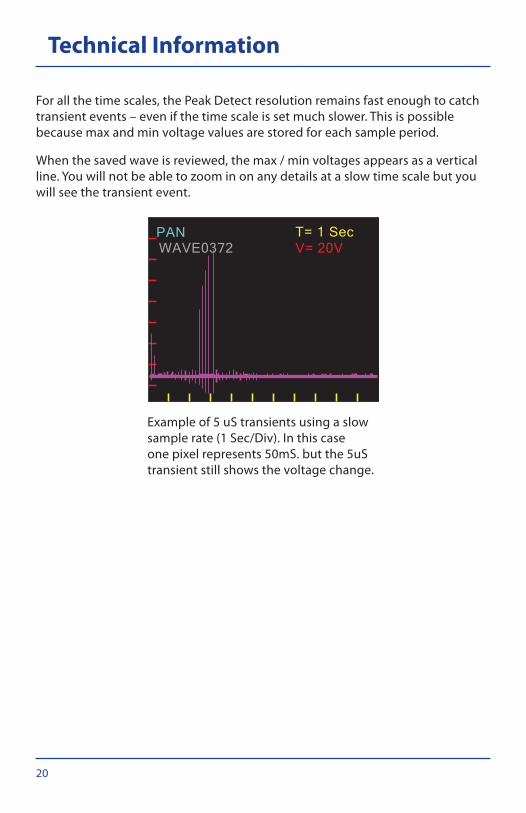
Forallthetimescales,thePeakDetectresolutionremainsfastenoughtocatchtransient events – even if the time scale is set much slower. This is possible because max and min voltage values are stored for each sample period.
When the saved wave is reviewed, the max / min voltages appears as a vertical line.Youwillnotbeabletozoominonanydetailsataslowtimescalebutyouwill see the transient event.
Exampleof5uStransientsusingaslowsamplerate(1Sec/Div).Inthiscaseonepixelrepresents50mS.butthe5uStransient still shows the voltage change.
PANWAVE0372 V= 20V
T= 1 Sec

21
Technical Information
Voltage Scales DuringLivewaveviewingthereareeightAutoWaveamplifiergainsettings.Thevoltage scale setting at the time a wave is captured determines the resolution of thedigitizedwave.Belowisachartthatshowsthescalesandtheresolution.
Vertical Scale V= Unipolar Range
Bipolar Range Volts Per A/D Bit
100mV 1V +/-500mV 1mV
200mV 2V +/-1V 2mV
500mV 5V +/-2.5V 5mV
1V 10V +/-5V 10mV
2V 20V +/-10V 20mV
5V 50V +/-25V 50mV
10V 100V +/-50V 100mV
20V 150V +/-75V 200mV
AswithsettingTimeScales,theAutoWaveVoltageScalesarecompressed5Xforlive viewing. The captured wave can be expanded to show more voltage detail than could be seen during the live viewing.
TheAutoWaveinputhasanadjustablebiasthatallowsmaximumuseofthefulldynamicvoltagerange.IfviewingbipolarACthezerovoltagereferencelineshouldbesetinthemiddleoftheLCDtoallowbipolarviewing.
IfthesignalisACbutbiasedpositive(mostautomotivesignals)thezerolinecanbemovedtonearthebottomoftheLCDwindow.Whenthisisdonetheeffective input voltage for each range is doubled. This allows waves to be saved withmoredetail(lessvoltsperbit)byzoominginmorewithoutoverscaling.

22
Specifications
VoltageInputRange +/-150V(approx.170VP/PviewableonLCD)
Input Impedance 100Kohms
SampleRate 1Ms/Sec@100uS/Division
Voltageresolution 1024points(10-bit)
PeakDetect 2uSresolutiononallrangesbelow100uS.
VoltMeter +/-150VDC
Accuracy +/-2%FS(perrange)
Current Approx.50mA
VoltageResolution 1mV(1Vrange)
VoltageRanges 150V,100V,50V,20V,10V,5V,2V,1V
TrendTimeRanges 20S,15S,10S,5S,2S,1S,.5S,.2S,.1S
CameraTimeRanges 50mS,20mS,10mS,5mS,2mS,1mS,500uS, 200us, 100 us.
Zoom 20Xzoominto1/20zoomout(rangedependent)
SampleDepth 4096samplebuffer(min/maxstorage)
Storage upto9999wavesonSDcard
Bitmaps Color220X176pixels–savedonSDcard

23
Contact Information
If you have any questions about our products including technical assistance, callourcustomercaredepartmentduringstandardbusinesshoursEST.Ifacustomer care representative directs you to return any equipment, be sure to include these items:
• awrittendescriptionoftheproblem;• thenameandtelephonenumberofyourcontactperson;• yourshippingaddress,and• ourreturnauthorizationnumber(fromcustomercare).
Customer care and tech support: 800/342-5080
Service and repair center: 662/453-6212
Fax: 216/761-9879
E-mail: [email protected]
Service address: Hickok Inc.Automotive Group1716 Carrollton Avenue Dock EGreenwood, MS 38930
LikeUsonfacebookatwww.facebook.com/hickokwaekon
Learnaboutnewproducts&promotions,telluswhatnewproductsyou’dliketosee,gotaproductquestion?AskourMasterTechnicians!
Sign-upforemailalertsatwww.hickok-inc.com/subscribe.html
Bethefirsttohearaboutnewproducts&services,promotions,andmore…
Subscribetoourvideochannelatwww.youtube.com/hickokincorporated
Watch the latest product and how-to videos
Visitourwebsiteatwww.hickok-inc.com
Getthelatestproductinfo&support,updateyourHickoksoftware,locateadistributor, download the latest product catalog, and more. . .

02491-108
Warranty
Subject to the conditions that follow and are noted below, this product is warranted to be free from defects in material and workmanship, under proper use and in accordance with the manufacturer’s written recommendation and specifications, for a period designated below on all products:
• This product carries a one year limited warranty.
The manufacturer’s obligation under this warranty is limited to unaltered products returned to the manufacturer by the initial end user of the new products. Therefore, this warranty does not cover any products resold by the end user to third parties, nor any reconditioned products sold as such, by the manufacturer. The sole remedy for any such defect shall be the repair, or replacement, of the product at the sole discretion of the manufacturer. This warranty does not cover expendable parts, such as batteries, nor does it cover shipping or handling. In addition, manufacturer is not liable for any loss or damage to product during shipping.
In the event it is determined that the product has been tampered with, or altered in any way, this warranty is void and all claims against the product will not be honored. All warranty claims must be submitted as outlined by the manufacturer and shall be processed in accordance with the manufacturer’s established warranty claim procedures. These procedures include provisions that proof of purchase must be established (by either warranty card from the seller or by point of purchase receipt) and that the manufacturer will make every attempt to return ship the product within one business day from receipt of the returned product, freight prepaid.
In addition, all maintenance procedures, as outlined by the product manuals, should be followed for the warranty to be kept in force. Should the product not be used in accordance with procedures as specified, or if the product otherwise fails outside of the warranty, the manufacturer reserves the right to make such judgment and the party returning the product will be notified that written notification will be necessary to repair the product at a cost which the manufacturer deems as reasonable. The product will then be shipped back to the customer, COD; or as the manufacturer deems appropriate.
This is the only authorized manufacturer’s warranty and is in lieu of all other expressed, or implied, warranties or representations, including but not limited to any implied warranties of merchantability or fitness or any other obligations on the part of the manufacturer. In no event will the manufacturer be liable for business interruptions, loss of profit, personal injury, costs of delays, or any special, indirect, incidental or consequential damages, costs or losses.