Embed Size (px)
Citation preview

Operation Instructions for Autoalign VH8 3D Four-wheel Aligner
1
Autoalign VH8 3D Wheel Aligner
Operational Manual
Operation Instructions for Autoalign VH8 3D Four-wheel Aligner
2
Chapter 1 Basics of Four-Wheel Alignment Read this chapter to acknowledge the following: 1. Vehicle structures related to alignment; 2. Concept & alignment parameter introduction of four-wheel alignment; 3. Work-flow of four-wheel alignment; 4. Alignment adjustment method, fault diagnosis & troubleshooting of vehicles; 5. Supporting equipment for aligner. 1.1 Introduction to vehicle structures related to alignment
Before learning the knowledge of alignment, please get a brief understanding of the vehicle structures related to alignment, namely, suspension system and driving system. 1.1.1 Suspension system
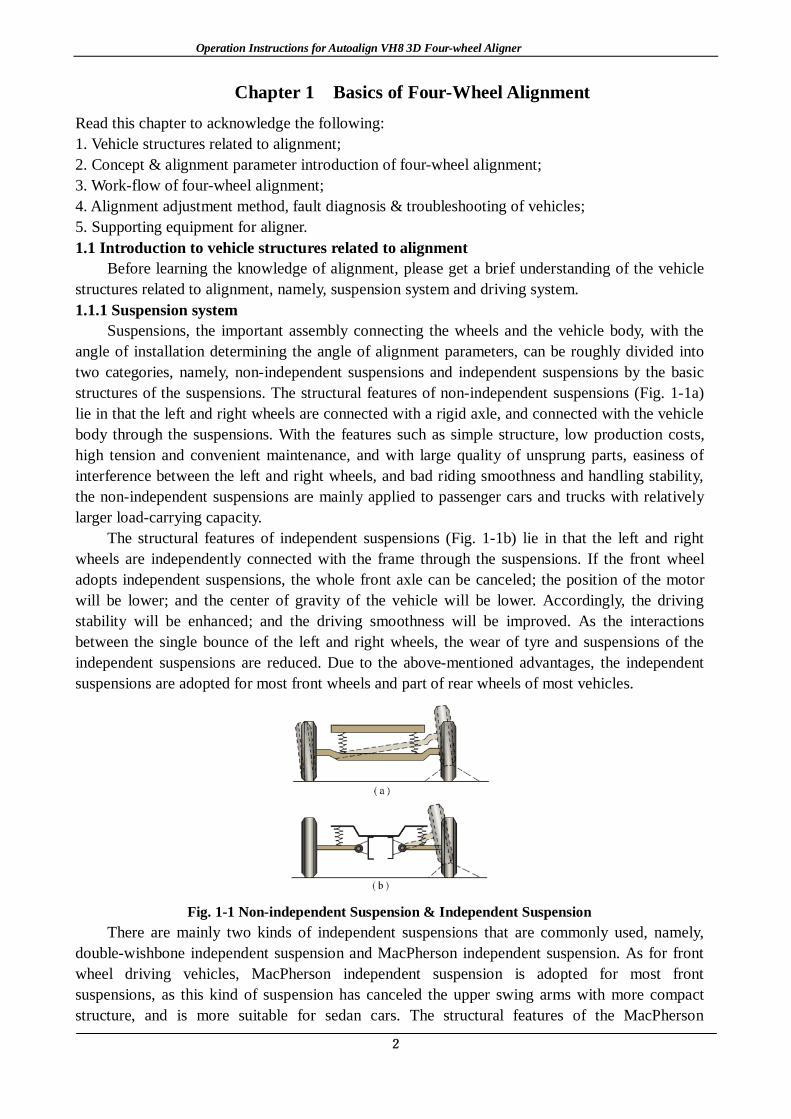
Suspensions, the important assembly connecting the wheels and the vehicle body, with the angle of installation determining the angle of alignment parameters, can be roughly divided into two categories, namely, non-independent suspensions and independent suspensions by the basic structures of the suspensions. The structural features of non-independent suspensions (Fig. 1-1a) lie in that the left and right wheels are connected with a rigid axle, and connected with the vehicle body through the suspensions. With the features such as simple structure, low production costs, high tension and convenient maintenance, and with large quality of unsprung parts, easiness of interference between the left and right wheels, and bad riding smoothness and handling stability, the non-independent suspensions are mainly applied to passenger cars and trucks with relatively larger load-carrying capacity.
The structural features of independent suspensions (Fig. 1-1b) lie in that the left and right wheels are independently connected with the frame through the suspensions. If the front wheel adopts independent suspensions, the whole front axle can be canceled; the position of the motor will be lower; and the center of gravity of the vehicle will be lower. Accordingly, the driving stability will be enhanced; and the driving smoothness will be improved. As the interactions between the single bounce of the left and right wheels, the wear of tyre and suspensions of the independent suspensions are reduced. Due to the above-mentioned advantages, the independent suspensions are adopted for most front wheels and part of rear wheels of most vehicles.
Fig. 1-1 Non-independent Suspension & Independent Suspension
There are mainly two kinds of independent suspensions that are commonly used, namely, double-wishbone independent suspension and MacPherson independent suspension. As for front wheel driving vehicles, MacPherson independent suspension is adopted for most front suspensions, as this kind of suspension has canceled the upper swing arms with more compact structure, and is more suitable for sedan cars. The structural features of the MacPherson

Operation Instructions for Autoalign VH8 3D Four-wheel Aligner
3
independent suspension lie in that it is used as the damping sliding column and support of the suspension. The upper bearing of the sliding column has been installed with bearings, upper spring seat and the vibration isolator installed between the upper side of the spiral spring and the spring seat. [Typical structure introduction]
The functions of the main components of MacPherson independent suspension system are summarized as follows (Fig. 1-2):
(1)Spiral spring—To correctly set the height of the suspensions; control the suspension travel; and absorb the pavement impacts; (2)Damping sliding column—To absorb the pavement impacts; and add proper resistance to the up-and-down movement of the suspension; (3)Lower swing arm—To control the lateral movement of the wheel; (4)Stabilizer anti-roll bar—To reduce the inclination of the vehicle body when the vehicle makes a turn; (5)Upper bearing of the sliding column—To isolate the sliding column, the springs and the vehicle body; and provide rotation axis for the sliding column and the spring assembly; (6)Ball head—To connect the external end of the lower swing arm and swivel joint to keep the sliding column, springs and the knuckle rotate around it.
Fig. 1-2 MacPherson Independent Suspension
Double-wishbone independent suspension (Fig. 1-3) is composed of upper and lower swing arms and spiral springs. Most of modern vehicles adopt the double-wishbone independent suspension with unequal arms. As the upper swing arm of this kind of suspension is shorter than the lower one, when the wheel moves up and down, the movement radian of the upper swing arm is smaller than that of the lower one; at this time, the upper side of the tyre will move inward slightly, while the movement of the bottom is extremely slight, which may reduce the tyre wear, improve the driving smoothness and the direction stability.
Fig. 1-3 Double-wishbone Independent Suspension

Operation Instructions for Autoalign VH8 3D Four-wheel Aligner
4
Some suspension mechanism can adjust the above ground level of the vehicle (such as the torsion bar spring suspension), adjust the preload of the torsion bar by the adjusting bolt at the fixed end so as to change the height of the vehicle body. When adjusting, pay attention to the height of the vehicle body, which shall be within the regulated scope, as it may impact the measurement accuracy of the camber and kingpin, and the running performance and tyre wear of the vehicle. 1.1.2 Driving system
Tyre, the main role in the driving system related to the alignment, is also the one with the most contact in the four-wheel alignment. At first, let’s recognize the model of the tyres through the tyre mark.
The tyre mark is on the sidewall with the contents including tyre type, end face width, flat ratio, structure type, rim diameter, load capacity and speed rating, etc. The tyre marks can be divided into metric mark and the British system mark. Taking the former ‘P 205/75 R 15 86H’ as an example to specify the meaning of each letter and number:
P——Tyre type (P refers to “passenger car”; T refers to “temporary tyre”); 205——End face width (Unit: ‘mm’); 75——Flat ratio (The ratio between the end face height and width×100%); R——Tyre structure type (R refers to “radial tyre”; B refers to “bias belted tyre”; and D
refers to “Diagonal tyre”); 15——Rim diameter (Unit: ‘inch’); 86——Load coefficient * (‘86’ refers to the max. load is 5.30KN); H——Speed rating* (‘H’ refers to the max. running speed is 210km/h). Tyre can be divided into three categories, namely, diagonal tyre, radial tyre and bias belted
tyre by the carcass ply structure. The cord line of the radial tyre and the center line of the tyre are at a right angle with radial arrangement. Adopting steel cords, with the features such as small rolling resistance, good steering performance, long tread service life, good cushioning performance and good adhesion, most radial tyres are used for the vehicles. Moreover, with the continuous improvement of the vehicle performance, the radial tyre with low flat ratio will be adopted by most vehicles due to its advantages such as wide tread, high carrying capacity and great ground adhesion. But this kind of tyre is thin in sidewall and poor in lateral stability.
Attention shall be paid to the following when using the tyres:
(1)The air pressure to the tyre shall be inflated according to the pressure regulated for the tyre; (2)The vehicle shall not be overloaded; (3)Good four-wheel alignment shall be guaranteed; (4)Operation time for crash maneuver, sharp turn and crash acceleration shall be reduced; and (5)Attention shall be paid to regular rotation (See Fig. 1-4 for the rotation method).

Operation Instructions for Autoalign VH8 3D Four-wheel Aligner
5
Fig. 1-4 Tyre Rotation Method
1.2 Introduction to terms of four-wheel alignment 1.2.1 Definition of four-wheel alignment
Four-wheel alignment refers to the installation angle of the wheels and the suspension system of the vehicles.
The aim to set the parameters of four-wheel alignment is to guarantee the stability and easiness of control during the straight running of the vehicle; to guarantee that the wheels will not result in any sliding; and to reduce the driving resistance and tyre and suspension wear. 1.2.2 Introduction to parameters 1.2.2.1 Wheel camber (Fig. 1-5)
Fig.1-5 Camber Angle
1.2.2.1.1 Definition: Camber angle is the angle between the center line through the tyre of the no-load vehicle
parking still on the flat road and the vertical line of the vertical ground, and is also the outward or inward inclined angle between the top of the tyre and the bottom. If the top end is inclined outward, it is called positive camber; on the contrary, it is called negative camber. The unit of the camber is “degree” or “point”. 1.2.2.1.2 Function:
One of the significant functions of the camber is to create the camber thrust, reduce the tyre cornering stiffness, and increase the under-steering trend of the front wheel. The ideal camber of the wheel shall be zero, that is to say, the tyre shall be perpendicular to the ground. But in consideration of the factors such as pavement irregularity, auto load and sharp turn, camber must be set for the wheels. In addition, correct camber can guarantee the well contact between the tyre and the ground, increase the tyre adhesion, and improve the dynamic property of the vehicle. 1.2.2.2 Wheel toe-in (Fig. 1-6)

Operation Instructions for Autoalign VH8 3D Four-wheel Aligner
6
Fig. 1-6 Toe-in 1.2.2.2.1 Definition:
Seeing from the front side of the vehicle, measure the distance between the center line of the left and right tyres at the position that the two wheel axles are of the same height. The difference between the front end distance and rear end distance of the wheel is called as toe-in. That is to say, the coaxial wheels are not parallel but perpendicular to the axle. If the distance of the front end is larger than that of the rear end, it is negative toe-in, otherwise, it is positive toe-in, and if the two are equal, it is zero toe-in. The unit shall be “degree” or “point”.
In this alignment system, the unit of toe-in can be “mm”. See 3-4-5 for unit setting. 1.2.2.2.2 Function:
The function of the toe-in is mainly to guarantee that the wheels can take parallel pure rolling movement while straight running. Generally, during the straight running of the rear wheel drive vehicle, the front wheel tends to negative toe-in, in which case, the tyre will have the sliding phenomenon while rolling, which increases the running resistance and exacerbates the tyre wear. Therefore, at the still state of the vehicle, small positive toe-in of the wheel will be set. The front wheel drive vehicle has the trend to make the front wheel increase the toe-in, and therefore, smaller negative toe-in of the front wheel will be set. 1.2.2.3 Caster (Fig. 1-7)
Fig. 1-7 Caster 1.2.2.3.1 Definition:
Kingpin, also called as steering kingpin, is the rotation center of the wheel steering. The vertical axle used as kingpin has already disappeared in modern automobiles, but the rotation center exists. In the double-wishbone independent suspension system, the concept of kingpin refers to the wire of the upper and lower ball heads; in the MacPherson independent suspension system, the concept of kingpin refers to the wire between the lower ball head and the upper bearing of the damping sliding column.

Operation Instructions for Autoalign VH8 3D Four-wheel Aligner
7
1.2.2.3.2 Function: With the function to create the wheel aligning torque, the caster is an important parameter to
guarantee the running stability of the vehicle. The aligning torque refers to the torque making the steering wheel recover to the position of straight running, and it is created by the side reaction of the ground on the tyre. 1.2.2.4 SAI (Fig. 1-8)
Fig. 1-8 SAI
1.2.2.4.1 Definition: In the double-wishbone independent suspension system, SAI refers to the inward inclined
angle between the upper ball head and the lower ball head seen from the anterior-posterior direction; and the SAI of MacPherson independent suspension system is the inward inclined angle between the damping sliding column support and the lower ball head. It is regulated that the value will be positive if the ball head inclined inward, and will be negative if the ball head inclined outward. The unit shall be ‘degree’ or ‘point’. 1.2.2.4.2 Function:
SAI also has the function of steering wheel return. In addition, SAI, combined with the front wheel camber, can determine the offset, and thus will impact the tyre wear and the easiness of steering. The steering wheel return function of SAI is working through the vehicle weight. 1.2.2.5 Set back (Fig. 1-9)
Fig. 1-9 Set Back
1.2.2.5.1 Definition: Set back refers to the set back position of a front wheel relative to another front wheel of the
vehicle. In the four-wheel alignment measurement, set back is represented by the non-parallelism of the anterior-posterior axis with the unit of ‘degree’ or ‘point’. The other measurement method of the set back is the difference between the front and rear wheels on both sides. 1.2.2.5.2 Effect:
Generally, slight set back will not affect the maneuverability of the vehicle, but serious set back will minify the caster value of the set back wheel, which will result in the off tracking toward the set back wheel while the straight running of the vehicle.

Operation Instructions for Autoalign VH8 3D Four-wheel Aligner
8
1.2.2.6 Thrust angle (Fig. 1-10)
Fig. 1-10 Thrust Angle
1.2.2.6.1 Definition: The thrust angle is an overall parameter of the rear axle, and is the included angle between
the rear axle thrust wire and the geometric center line of the vehicle. The geometric center line is the wire running through the centers of the two front wheels and the two rear wheels. Theoretically, the thrust wire refers to the imaginary line extending forward and forming an angle of 90 degree with the center lines of the two rear wheels, but in fact it is the movement trail of the rear axle. When the thrust wire directs the right front direction, the thrust angle will be positive; and when it directs the left front direction, the thrust angle will be negative. 1.2.2.6.2 Effect:
Vehicles in ideal condition have no thrust angles. If the thrust angle exists, the movement trail of the rear axle will misalign with the geometric center line of the vehicle, which will result in the steering tension of the vehicle and abnormal wear of the tyre. In addition, the exist of the thrust angle will also cause steering wheel misalignment with the phenomenon that the steering wheel will deviate toward the thrust angle while straight running. 1.2.2.7 Included angle (Fig. 1-11)
Fig. 1-11 Included Angle 1.2.2.7.1 Definition:
As is mentioned above, the included angle is the sum of the front wheel camber value and the SAI value, that is to say, seen from the anterior-posterior direction of the vehicle, the included angle is the angle between the kingpin and the tyre plane. 1.2.2.7.2 Function:
The included angle can be used as the inspection angle to diagnose the faults of the suspension system; and the included angle can also determine the offset value to guarantee the easiness of steering, the vehicle acceleration and the direction stability while braking, and reduce the tyre wear.
Offset, also known as scrub radius, is the distance from the intersection point between the

Operation Instructions for Autoalign VH8 3D Four-wheel Aligner
9
tyre center line and the ground to the intersection point between the kingpin extension line and the ground (as is shown in Fig. 1-11). If the intersection point between the kingpin extension line and the ground is inside the center line of the tyre and the ground, it is called as positive offset; otherwise, it is called as negative offset. Negative offset plays a role in keeping the direction stability of the vehicle at the time of crash acceleration or crash maneuver, and therefore, current vehicles are most set with negative offset. As for the front wheel driving vehicles, if the offsets are unequal during crash acceleration, off tracking will occur, which is called as accelerated off tracking. Offset is an item of wheel arrangement adjustment. When replacing non-standard wheels, attention shall be paid to the offset. When installing the wheels, if the offset is inconsistent, the difference between the offset on both side, the maneuverability will be affected. Therefore, the replacing of the wheel rims and tyres shall conform to the vehicle delivery requirements. 1.2.2.8 Toe-out on turns (Fig. 1-12)
Fig. 1-12 Toe-out on turns
1.2.2.8.1 Definition: When steering, all the wheels of the vehicle shall have the same instantaneous center of
rotation to guarantee the pure rolling movement of the wheels. As is shown in the fig.1-12, to guarantee that there is only one center of rotation (O), the two front wheels must have different steering angles. The relation between the two steering angles shall be ctgα-ctgβ=B/L, in which, β refers to the steering angle turning to the inside wheel; α refers to the steering angle turning to the outside wheel; B refers to the wheel tread; and L refers to the wheel base. The relation of the steering angle shall be β>α. Toe-out on turn refers to the steering angle difference between the two steering wheels when the inside steering wheel turns at 20°. Generally, the outside steering wheel turns as about 18.5~19°. 1.2.2.8.2 Function:
To reduce the resistance to the wheels when turning, guarantee the pure rolling movement, and reduce the tyre wear. 1.3 Introduction to general knowledge of alignment :1.3.1 Advantages of four-wheel alignment of vehicles
①To guarantee the safety of driving; ② To keep the vehicle running straightly; ③To increase the sense of manipulation of driving; ④ The steering wheel returns automatically after steering, which reduces the driving
fatigue; ⑤ When the vehicle runs, the wheels has no sliding, which reduces the tyre wear; ⑥To reduce the losses of the suspension system components; ⑦ To reduce the driving resistance and oil consumption; and

Operation Instructions for Autoalign VH8 3D Four-wheel Aligner
10
If each system related to the alignment of the vehicle is normal
⑧ To guarantee the good contact between the tyre and the ground and increase the tyre adhesion.
1.3.2 Time for four-wheel alignment After every running of 10000 km or six months Pulling the vehicle left or right while straight running Need to hold the steering wheel while straight running Steering wheel misalignment while straight running With the feel that the vehicle body will float or swing Single wheel wear of front wheel or rear wheel After installing new tyres Being repaired after collision accidents After changing and replacing new suspensions or related steering accessories After running of 3000 km of a new vehicle
1.3.3 Driving problems resulting from incorrect four-wheel alignment Orientation Angle Reasons Driving Problems
Camber
Overlarge Tyre outer wear and suspension component wear Oversmall Tyre inner wear and suspension component wear
Unequal The vehicle runs off tracking toward the big camber direction while straight running
Toe-in upright Shape Tyre outer featheriness wear and
inner quick wear Floating steering wheel Inverted
Shape Tyre inner featheriness wear and outer quick wear
Caster
Overlarge Heavy steering wheel while steering
Oversmall Swinging steering wheel with poor returnability while straight running
Unequal The vehicle runs off tracking toward the small rearward direction
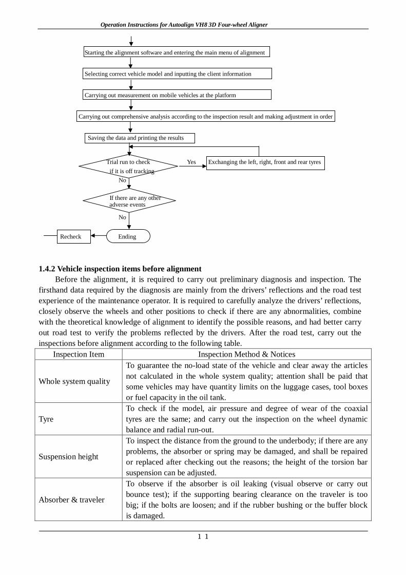
1.4 Alignment operating procedure 1.4.1 Standard operation flow chart of four-wheel alignment
Enquiry & commissioning and
failure understanding
Inspection before alignment: Inspecting one by one carefully
No Changing or repairing
as required
Yes
Driving the vehicle steadily onto the alignment platform, placing the front wheel in the center of the
turntable and the rear wheel on the slip plate and covering the wheel by wedge-shaped block.
Installing and fixing the target plate
Operation Instructions for Autoalign VH8 3D Four-wheel Aligner
11
Starting the alignment software and entering the main menu of alignment
Selecting correct vehicle model and inputting the client information
Carrying out measurement on mobile vehicles at the platform
Carrying out comprehensive analysis according to the inspection result and making adjustment in order
Saving the data and printing the results
Trial run to check Yes Exchanging the left, right, front and rear tyres
if it is off tracking No
If there are any other
adverse events
No
Recheck Ending
1.4.2 Vehicle inspection items before alignment
Before the alignment, it is required to carry out preliminary diagnosis and inspection. The firsthand data required by the diagnosis are mainly from the drivers’ reflections and the road test experience of the maintenance operator. It is required to carefully analyze the drivers’ reflections, closely observe the wheels and other positions to check if there are any abnormalities, combine with the theoretical knowledge of alignment to identify the possible reasons, and had better carry out road test to verify the problems reflected by the drivers. After the road test, carry out the inspections before alignment according to the following table.
Inspection Item Inspection Method & Notices
Whole system quality
To guarantee the no-load state of the vehicle and clear away the articles not calculated in the whole system quality; attention shall be paid that some vehicles may have quantity limits on the luggage cases, tool boxes or fuel capacity in the oil tank.
Tyre To check if the model, air pressure and degree of wear of the coaxial tyres are the same; and carry out the inspection on the wheel dynamic balance and radial run-out.
Suspension height
To inspect the distance from the ground to the underbody; if there are any problems, the absorber or spring may be damaged, and shall be repaired or replaced after checking out the reasons; the height of the torsion bar suspension can be adjusted.
Absorber & traveler
To observe if the absorber is oil leaking (visual observe or carry out bounce test); if the supporting bearing clearance on the traveler is too big; if the bolts are loosen; and if the rubber bushing or the buffer block is damaged.

Operation Instructions for Autoalign VH8 3D Four-wheel Aligner
12
Wheel bearing
To check the abnormal wheel rotation noise caused by the bearings (identify bearing failure) and the bearing clearance (if the wheel has any horizontal movement); if there are any problems, it is required to carry out cleaning, replacing or adjustment.
Swing arm, bushing and ball head
To check if the swing arm is bending or deforming; if the swing arm bushing is wearing or loose; and if the ball head has radial or axial movement. If there are any problems found, replacing must be carried out. Note: It is required to lift up the vehicle to check the item.
Steering transmission device & steering tie rod ball head
To check if the steering transmission device is bending or deforming and if the steering tie rod ball head is loose. If there are any problems found, replacing must be carried out. The inspection of the steering mechanism can also be carried out through the clearance of the steering wheel.
8 、 Stabilizer bar & bushing
To check if the stabilizer bar is deforming; and if the fixing bolt, vibration isolator and hinge of the stabilizer bar is wearing. If there are any problems found, replacing must be carried out. (The damaged stabilizer bar will result in excessive side sway of the vehicle body, which will cause cracking sounds on rough roads.)
1.4.3 Introduction to the standard working flow of the four-wheel alignment 1.4.3.1 Start the computer and run the alignment system; 1.4.3.2 Drive the vehicle to the right position: Adjust the position of the sliding plate according to the wheel track and the wheel base to put the front wheel in the center of turntable and the rear wheel on the side sliding plate, pull the handbrake, and unplug the plug of the turntable and side sliding plate; 1.4.3.3 Carry out overall inspection on the vehicle: See the above table for the details of the items; some of the items such as the inspection of the ball head, wheel bearing and bushing need to lift the vehicle (as is shown in Fig. 1-13). At this time, loosen the handbrake, and the inspection will be completed. If there are any unqualified positions, corresponding adjustment and replacing shall be carried out. Pull the handbrake; push the turntable and side sliding plate inward; lay down the vehicle; and press up and down for several times to make the suspension recover the natural status.
Fig. 1-13 Inspection Method for Lower Swing Arm Ball Head
1.4.3.4 Select a proper height for lifting the vehicle (The scissor lift or four-column lift shall adopt mechanical lock); 1.4.3.5 Install the rack: Adjust the rack according to the rim size; screw up the screw of the regulating handle to guarantee that the top ends are on the same level; fix the handle screw of the top ends to guarantee that the top ends are perpendicular to the rack; and hold the tyre tightly with

Operation Instructions for Autoalign VH8 3D Four-wheel Aligner
13
the hook; 1.4.3.6 Install the sensor head: Pay attention to the position of the sensor head; adjust the sensor head leveling; and turn on the power switch; 1.4.3.7 Open the alignment software (See Chapter 3 for software operation); 1.4.3.8 Rim compensation: If there are rim deformations of the detected vehicles, implement the function to carry out out-of-round compensation for the rim data to improve the accuracy. The rim compensation needs to lift up the vehicle and loosen the handbrake. After the inspection is finished, pull the handbrake, and pay attention to the position of the turntable and the side sliding plate when laying down the vehicle; 1.4.3.9 Install the brake holder; adjust the sensor head level; turn the steering wheel as per requirement of the program; turn it to left by 10º first and then turn it to right by 10 º; and measure the caster and SAI; 1.4.3.10 Put the steering wheel straight as the arrow shows; fix the steering wheel by the steering wheel holder; and measure the rear wheel camber, rear wheel toe-in, front wheel camber, and front wheel toe-in in sequence; 1.4.3.11 Make proper adjustment according to the inspection results with the adjustment order as follows: rear wheel camber, rear wheel toe-in, kingpin adjustment, front wheel camber and front wheel toe-in. If it requires to lift up the vehicle during the adjustment process, attention shall be paid to the position of the turntable and side sliding plate. When adjusting the front wheel toe-in, attention shall be paid to the straightening of the steering wheel and the change of the sensor head; and 1.4.3.12 After the adjustment is finished, drive the vehicle off the alignment platform slowly; carry out the trial run outside; and make corresponding measurement and adjustment according to the effects of trial run. 1.5 Alignment adjustment method introduction
In terms of the parameter inspection and adjustment of the above items, four-wheel alignment is relatively easier, but four-wheel alignment not only has the alignment angle problems of the tyre and kingpin, but most importantly, it comes to every aspect of the vehicle chassis. The suspension system, steering system, brake system, vehicle frame and body all have connections with the alignment. Therefore, it does not only require advanced four-wheel aligner, but also require the operator with profound alignment knowledge and rich vehicle adjustment experience to do the four-wheel alignment well. 1.5.1 Parameter adjustment method 1.5.1.1 Toe-in adjustment method 1.5.1.1.1 Toe-in of the front wheel
The adjustment of toe-in is relatively easier, which is mostly made through changing the length of the steering tie rod. As is shown in Fig. 1-14, the adjustment steps are as follows: Loosen the fastening bolt or nut and rotate the tie rod. As one end of the tie rod is right hand screw and the other end is left hand screw (or inside ball head), the length of the steering tie rod will change, and thus change the toe-in value.

Operation Instructions for Autoalign VH8 3D Four-wheel Aligner
14
Fig. 1-14 Adjustment of Front Wheel Toe-in
Notes: 1. As for the vehicles with steering tie rod inner ball head, it is required to loosen the dust cover when rotating the tie rod to adjust the toe-in. The dust cover rotation shall be prohibited to avoid damage! 2. The steering tie rods on both sides shall be synchronously adjusted with the length
being consistent to avoid any impacts on the steering angle or danger of shredding. 1.5.1.1.2 Toe-in of rear wheel
Generally, the toe-in of rear wheel cannot be adjusted. If the inside of the lower swing arm is connected with the eccentric bolt, the adjustment can be made through the eccentric bolt (e.g.: Charade, Tianjin), as is shown in Fig. 1-15.
Fig. 1-15 Rear Wheel Toe-in Adjustment
In addition, the rear wheel toe-in of the Volkswagen series vehicles can be adjusted through the full-contact gasket, as is shown in Fig. 1-16,
Fig. 1-16 Rear Wheel Parameter Adjustment
Test result: The toe-in of 3.17mm make the tyre available for a lateral movement (sliding) of 3.3m when the vehicle runs every 1.6km, and the lateral movement is the ‘culprit’ that results in the tyre featheriness wear and quick wear. As the changes of the kingpin and camber will

Operation Instructions for Autoalign VH8 3D Four-wheel Aligner
15
lead to toe-in change, toe-in shall be the last parameter to adjust among all the alignment parameters.
1.5.1.2 Camber adjustment method 1.5.1.2.1 Front wheel camber
The adjustment methods of the front wheel camber can be briefly divided into the following categories by the suspension types:
1.5.1.2.1.1 Generally, positions for the front wheel camber adjustment of the MacPherson independent suspension are as follows (as is shown in Fig. 1-17):
Fig. 1-17 Positions for the Front Wheel Camber Adjustment of the MacPherson Independent
Suspension A——Top seat of absorber; typical model: Audi 100 series; B——Adjustment of lower support of the absorber or replacing and adjusting the eccentric bolt; typical model: Jetta and Charade; C——Position adjustment of lower swing arm ball head; typical model: Santana; D——Inside adjustment of lower swing arm; typical model: Wantong minibus.
1.5.1.2.1.2 The adjustment position of the double-wishbone independent suspension is generally at the position of the upper control arm with the main types including gasket type (Fig. 1-18), eccentric bolt type and long slot type, etc.
Fig. 1-18 Adjustment Parameters of the Upper Control Arm
If the camber cannot be adjusted, the methods of components exchange or external force correction will be adopted (See 1.7.5 Application of eccentric bolt & camber corrector for details). 1.5.1.2.2 Rear wheel camber adjustment
Generally, the rear wheel camber is not adjustable, but the rear wheel camber of the Volkswagen series can be adjusted through adjusting the full-contact gasket with the same method

Operation Instructions for Autoalign VH8 3D Four-wheel Aligner
16
shown in Fig. 1-15; 1.5.1.3 Caster adjustment
The caster adjustment has mainly three types, namely, gasket type, eccentric bolt type and stay bar type.
1.5.1.3.1 Gasket adjustment type: The same method with that of the camber adjustment. If the added gasket thickness is different, the caster value will be changed;
1.5.1.3.2 Eccentric bolt type: In the double-wishbone suspension system, if the eccentric bolts inside the swing arm rotate by the same angle, the camber value can be adjusted; if the rotation angles of the two bolts are different, the caster value can be changed (as is shown in Fig. 1-19);
Fig. 1-19
1.5.1.3.3 Stay bar type: In some suspension systems, the front end of the lower swing arm stay bar has an adjustable device. Loosen the locking nut, and adjust the length of the stay bar. In this way, the caster value will be changed, the stay bar prolongs; and the caster become small; otherwise, the caster will become bigger (as is shown in Fig. 1-20);
Fig. 1-20 1.5.1.4 SAI adjustment
The SAI adjustment is generally synchronistical with that of the front wheel camber (with the same position and opposite direction) with the aim not to change the value of the included angle and the offset. When the camber angle and the SAI cannot be adjusted to the standard value at the same time, the camber angle shall be firstly settled, and the difference between the left and right SAI shall not be over 1.5°. If the SAI is out of the regulated scope, it shall be generally resulting from the bending lower swing arm, motor bracket shift or the misalignment of the upper support of the damping sliding column. 1.5.1.5 Set back
The set back is generally caused by impact. Sometimes, the caster angle can be adjusted within the standard scope, but the set back cannot be adjusted. To settle the problems thoroughly, the only way is to calibrate the motor bracket or the monocoque body to the standard value, which shall be finished by the metaler. 1.5.1.6 Suspension adjustment of Passat B5 (Audi A6)
Operation Instructions for Autoalign VH8 3D Four-wheel Aligner
17
The camber and toe-in constant value adjustment of Passat B5 (Audi A6) shall be carried out by adopting special tools. See 1.7.5 for details. 1.6 Vehicle fault diagnosis & troubleshooting
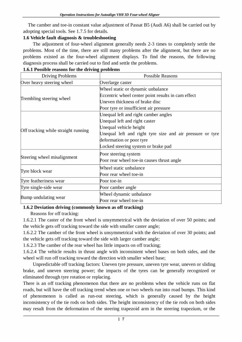
The adjustment of four-wheel alignment generally needs 2-3 times to completely settle the problems. Most of the time, there are still many problems after the alignment, but there are no problems existed as the four-wheel alignment displays. To find the reasons, the following diagnosis process shall be carried out to find and settle the problems. 1.6.1 Possible reasons for the driving problems
Driving Problems Possible Reasons Over heavy steering wheel Overlarge caster
Trembling steering wheel
Wheel static or dynamic unbalance Eccentric wheel center point results in cam effect Uneven thickness of brake disc Poor tyre or insufficient air pressure
Off tracking while straight running
Unequal left and right camber angles Unequal left and right caster Unequal vehicle height Unequal left and right tyre size and air pressure or tyre deformation or poor tyre Locked steering system or brake pad
Steering wheel misalignment Poor steering system Poor rear wheel toe-in causes thrust angle
Tyre block wear Wheel static unbalance Poor rear wheel toe-in
Tyre featheriness wear Poor toe-in Tyre single-side wear Poor camber angle
Bump undulating wear Wheel dynamic unbalance Poor rear wheel toe-in
1.6.2 Deviation driving (commonly known as off tracking) Reasons for off tracking:
1.6.2.1 The caster of the front wheel is unsymmetrical with the deviation of over 50 points; and the vehicle gets off tracking toward the side with smaller caster angle; 1.6.2.2 The camber of the front wheel is unsymmetrical with the deviation of over 30 points; and the vehicle gets off tracking toward the side with larger camber angle; 1.6.2.3 The camber of the rear wheel has little impacts on off tracking; 1.6.2.4 The vehicle results in thrust angle with inconsistent wheel bases on both sides, and the wheel will run off tracking toward the direction with smaller wheel base;
Unpredictable off tracking factors: Uneven tyre pressure, uneven tyre wear, uneven or sliding brake, and uneven steering power; the impacts of the tyres can be generally recognized or eliminated through tyre rotation or replacing. There is an off tracking phenomenon that there are no problems when the vehicle runs on flat roads, but will have the off tracking trend when one or two wheels run into road bumps. This kind of phenomenon is called as run-out steering, which is generally caused by the height inconsistency of the tie rods on both sides. The height inconsistency of the tie rods on both sides may result from the deformation of the steering trapezoid arm in the steering trapezium, or the

Operation Instructions for Autoalign VH8 3D Four-wheel Aligner
18
excessive wear of the installation liner of the rack and pinion steering gear. The unparalleled tie rod will make the tie rod and the lower swing arm unparallel.
Another off tracking phenomenon is that the off tracking direction is constantly changing, which is caused by the deformation of some components of the vehicle steering system. Put the wheels on the turntable, and turn the steering wheel from an end to the other end. If the resistance changes are uneven, it means that there are some components shapes have changed, and the short sound also indicates the component improperness or deformation. The loosen components of the suspension system or steering system will also lead to unstable direction deflection. It is required to recheck, replace and repair the components of the suspension system and steering system. 1.6.3 Steering wheel misalignment
When the vehicle is running on the flat pavement, without turning the steering wheel, the vehicle shall run straightly along the road right ahead. If the vehicle runs off tracking toward a certain direction, there must be off tracking driving defaults. The problem of the incorrect zero position of the steering wheel can be corrected only when the off tracking driving defaults are eliminated first. If the vehicle runs straightly but the steering wheel is not aligned, it means that the zero position of the steering wheel is not aligned, which may result from the component damages or improper installation. Generally, the zero position misalignment of the steering wheel results from the incorrect alignment angle. 1.6.3.1 Vehicle condition problems
The steering system components of some vehicles may be improperly installed. It is required to check the installation situation of each component including the axle, steering wheel and steering axle. Normally, there are marks for correct installation on the components. 1.6.3.2 Incorrect adjustment of steering wheel
When adjusting the front wheel alignment, if the toe-in is correct, but the steering wheel is not aligned, for instance, if the steering wheel inclines left, it is required to turn the steering wheel right to the aligned position first and lock in. At this time, the sub toe-in of the two wheels will change (the gross toe-in or toe-in sum basically remain unchanged). Adjust the steering tie rod at this time to make the toe-in of the two wheels return to the standard. Otherwise, if the steering wheel inclines right, it is required to turn the steering wheel left to the aligned position first and lock in. Then, rotate the adjusting sleeve on both sides to make the tie rods on both sides stretch and the wheel toe-in on both sides meet the standard. This is in terms of the vehicles with the tie rods behind the front wheel axis. As for the vehicles with the tie rods in front of the axis of the front axle, the process is just the reverse order.
In addition, the thrust angle caused by the incorrect rear wheel toe-in will not only result in tyre eccentric wear or tyre gnawing, but will also result in off tracking or steering wheel misalignment. Therefore, the adjustment of rear wheel toe-in shall not be ignored. As for all the vehicles with the rear wheel toe-in adjustable, it is required to adjust the rear wheel toe-in first; and then adjust the front wheel toe-in and other angles. The compensating four-wheel alignment can compensate the thrust angle that is not zero by adjust the front wheel toe-in angel to achieve the target of steering wheel alignment. 1.6.4 Trembling steering wheel
There are mainly three aspects for the steering wheel trembling, namely, braking fault, motor fault (including transmission system fault) and suspension system fault. The trembling diagnosis shall carry out the road test experiment to check if the trembling occurs at a special speed and the trembling is left-to-right trembling or up-to-down trembling, and record the motor rpm while the trembling. Meanwhile, check the operating brake and parking brake and observe if the trembling

Operation Instructions for Autoalign VH8 3D Four-wheel Aligner
19
occurs while using brake. In comprehensive consideration, the main reasons for trembling are as follows:
1. Tyre quality problem 2. Over-high air pressure 3. Unbalanced wheels 4. Rim out-of-round 5. Inconsistent tyre model 6. Absorber failure 7. Loosen rubber cot 8. Steering damper failure 9. Transmission shaft problem 10. Overlarge steering engine free travel 11. Loosen engine bracket 12. Girder crack 13. Clutch disc problem 14. Brake disc deformation 15. Motor problem 16. Overlarge caster 17. Overlarge toe-in 18. Overlarge camber positive value 19. Overlarge thrust angle
1.6.5 Abnormal tyre wear As is shown in the following Fig. 1-21, there are many reasons for abnormal tyre wear, and
therefore it’s extremely difficult to precisely find the real reason.
Fig. 1-21 Reasons for Tyre Wear
Generally, there are several cases as follows: (1)Inside wear caused by one of the following reasons:
① Negative toe-in angle ② Negative camber angle ③ Middle uplift pavement ④ Conic tyre ⑤ Incorrect rim specification
(2)Outside wear caused by one of the following reasons: ① Overlarge toe-in angle

Operation Instructions for Autoalign VH8 3D Four-wheel Aligner
20
② Overlarge camber angle ③ Middle uplift pavement ④ Too much sharp turns ⑤ Mass intro-city driving ⑥ Conic tyre ⑦ Incorrect rim specification
(3)Depression or sidewall wear caused by one of the following reasons: ① Take sharp turns when the pressure is insufficient ② Extremely low pressure (25% lower than normal pressure) ③ Mutual friction between the tyre and the vehicle components ④ Mutual friction between the tyre and the curbstone while vehicle parking
(4)Inside and outside wear caused by one of the following reasons: ① Extremely low pressure ② High speed running on bending pavement ③ Overloading
(5)Center wear The main reason lies in that the tyre pressure is too high. Few inconsistencies between
steel rim width and tyre can also cause similar phenomenon. (6)Feather wear
Lateral feather wear caused by one of the following reasons: ① Incorrect toe-in angle ② Sharp turns ③ Conic tyre It is highly possible that longitudinal feather wear is caused by sudden acceleration or braking.
(7)Depression or local pump is possibly caused by one or several of the following reasons: ① Poor wheel balance ② Poor damping system performance (damper, damping column ) ③ Out-of-round tyre ④ Loosened suspension system components
1.7 Introduction to Auxiliary Products 1.7.1 Installation & application of camber corrector 1.7.1.1 Dismantle the tyre; and fix the calibrated mount on the wheel hub (Select corresponding connection plates according to different models. To avoid the wear during the application process of the connection plates and prolong the service life of the connection plates, please put proper cashers between the fixing bolts and the connection plates). Pay attention that the lateral bubble of the bubble box shall be in the central position;
1.7.1.2 Carry out the following operation according to the positive and negative camber detected by the aligner, as is shown in Fig. 1-23:
A. Calibrate the positive camber angle: Install the oil hydraulic cylinder on corresponding steering rod. Install piercing plug on the head position of the oil hydraulic cylinder, and put the piercing plug at the end of the suspension.
B. Calibrate the negative camber angle: Install the oil hydraulic cylinder on corresponding steering rod. Install pull head on the head position of the oil hydraulic cylinder. At this

Operation Instructions for Autoalign VH8 3D Four-wheel Aligner
21
time, an end of the iron chain is fixed on the pull head, and the other end is tied up at the end of the suspension.
1.7.1.3 Adjust the dial on the bubble box I to zero; loosen the fixing screw of the bubble box I; rotate the bubble box I to make the longitudinal bubble H in the central position; and screw up the fixing screw of bubble box I. According to the difference between the camber angle detected by the aligner and the standard camber angle, and the rebound range (3~5%) of the corrector, rotate the dial to the required value, press the hydraulic jack K to make the oil hydraulic cylinder work till the longitudinal bubble H on the bubble box I returns to the central position, and therefore, the calibration of the camber angle completes.
Fig. 1-23 application of Camber Corrector
Safety Tips: 1. During the operation process of calibrating the camber, please do not stand at the expansion direction of the oil hydraulic cylinder to avoid accidents. 2. During the operation process, attention shall be paid to the protection measures to avoid the oil-pressure pipe and the joint part from extrusion. 1.7.2 Application of special tools for Passat B5 and Audi A6 1.7.2.1 Name & No. of main tools:
A. VAG1941——Special tool for adjusting camber B. VAG1925——Measurement & alignment frame C. VAG1925/4——Joint with fixed height
1.7.2.2 Front wheel camber adjustment
Adjustment principle: The front suspension of Passat B5 is independent suspension with the multi-link structure without independent adjustment device on each side, but with lower support arms on both sides connected with the sub frame. As the installation position of the sub frame has margin for movement, the movement of the lower support arms can be driven by changing the installation position of the sub frame, which will further change the camber angle of the front wheel. The special tool VAG1941 shall be required. 1.7.2.3 Measurement of toe-in constant value:
Adjustment purpose and principle: During the up and down movement of the independent suspension tyres, both the camber and the toe-in will change. To reduce the adverse phenomena such as the tyre wear resulting from the toe-in variation, change the included angle between the steering track rod and the lower support arm to control the curvature of toe-in variation, namely,

Operation Instructions for Autoalign VH8 3D Four-wheel Aligner
22
to control the range of variation of toe-in (constant value). Constant value measurement: Formula: S=C2-C1.
S——Toe-in constant value (Control range: 7’~11’); C1——Toe-in value when the car is not lifted; C2——Toe in value when the car is lifted by 60 mm ~62mm. Loosen the fixing bolt A
of the side ball head; 1.7.2.4 Toe-in constant value adjustment method (Fig. 1-24)
1) Unscrew the clearance adjusting bolt A; 2) Push down the adjusting bolt B; 3) Measure the constant value S according to the above measurement principle; 4)In case of disqualification, the above steps shall be repeated until it is qualified.
Fig. 1-24 Toe-in Constant Value Adjustment Method
Notes: A. When the vehicle is lifted up to 60mm, the lock pin of turntable cannot be
pulled out; and the tyre cannot leave the turntable; B. Relative motion cannot exist between the tyre and the turntable, and between
the turntable and the ground; C. It is required to recheck the toe-in after the value of S has been adjusted.
1.7.3 Application of full-contact gasket 1.7.3.1 Applicable vehicle type: Volkswagen series such as Santana, Jetta and Golf; Chrysler series such as Sundance, New Yorker and Imperial; and Ford series such as FESVA and ASPRE; 1.7.3.2 Specifications: There are totally eight kinds of angle specifications including 0.1°, 0.2°, 0.4°, 0.6°, 0.8°, 1.0°, 1.2° and 1.5° with the max. adjustment degree of 1.5°; 1.7.3.3 Adjustable angle: Rear wheel camber and rear wheel toe-in; 1.7.3.4 Operation instructions
Step 1: Make a comparison between the measured value displayed on the aligner and the camber angel and toe-in value regulated by the factory to determine the correction of the camber angel and toe-in value; Calculation method: Correction=Original value-measured value;
Step 2: Calculate the angle needs to be adjusted according to the measurement result; and select equivalent or similar gasket; as is shown in Fig1, dismantle the wheels and braking system of the above-mentioned vehicle type till the root of the rear axle; after installing the gasket, install the braking system and wheels in order. There is a mark on the gasket marked with the degree indicating the camber angle to be adjusted and the changing direction of the toe-in angle Put the

Operation Instructions for Autoalign VH8 3D Four-wheel Aligner
23
gasket face with numbers outward. Install along the direction perpendicular to the ground, the camber angle can be changed: The angle mark indicates upward—To enlarge the camber angle; The angel mark indicates downward —To reduce the camber angle; Install along the horizontal ground direction, the toe-in angle can be changed: The angle mark indicates backward—To enlarge the toe-in angle; The angel mark indicates forward —To reduce the toe-in angle;
Tips: 1. The full-contact gasket shall be used only in the drum brakes, and shall be prohibited for use in the disc brake to avoid the fault of brake failure!
2. At most two pieces of gaskets can be added on each wheel, and the sum can not be over 2°! 1.7.4 Application of eccentric bolt
The eccentric bolt adjustment components are applicable to MacPherson suspension with two bolts on the damper bracket. It is required to select the eccentric bolt components according to the round hole diameter size of the original bolt. After the eccentric bolts are changed, the camber angle can be changed by ±1.75° or so.
Bolt Model Application Vehicle type
12mm
Daihatsu: Charade; Chang’an: Alto; Chevrolet: Nova, Aveo; Dodge: Colt, Neon; Hyundai: Accent, Trajet; Mercury: Capri, Topaz, Tracer; Nissan: Maxima, Quest; Ford: Expectation, Escort, Explorer, Tempo; Volkswagen: Jetta, Golf, Passat; Mitsubishi: Galant, Eclipse; Plymouth: 9000;Chang’an star, Bluebird, Freema, Geely Srv., Ningbo Merrie, Zhonghua Bullet, Chery, Encore. Mazda 323/626/929/MPV/MX3/MX6/MR7, and Toyota, Isuzu, Suzuki, Renault, Peugeot , SAAB and other brands of vehicles with the strut bolts of 12mm.
14mm
Charade 2000; Dodge: Voyager, Neon; Nissan: Maxima; Toyota: Celica, Corona; Chrysler: Town and Country; Hyundai: Sonata; Plymouth: Voyager; Subaru: Legacy; Volvo: 850GLT,Nissan Cefiro, and other brands of vehicles with the strut bolts of 14mm.
14.5mm Shanghai GM: Buick
15mm Lexus: ES250, ES300; Toyota: Avalon, Camry, Celica, Corona, and other brands of vehicles with the strut bolts of 15mm.
16mm
Buick: LeSabre, Park Avenue, Regal, Riviera, Skylark; Chrysler: Concorde, LHS, New Yorker; Ford: Mustang, Thunderbird; Mercury: Capri, GrandMarquis; Chevroler: Beretta, Corsica, Cavalier, Camaro, Monte Carlo, Lumina; Cadillac: Allante, Fleeetwood, DeVille, SeVille; Dodge: Intrepid; Lincoln: Continental, Mark; Oldsmobile: Cutlass, 88, 98; Pontiac: Firebird, Grand Am, Grand Prix, Sunbird; and other brands of vehicles with the strut bolts of 16mm.
17mm Lexus: ES250, ES300; Toyota: Avalon, Camry, Celica, Previa, and other brands of vehicles with the strut bolts of 17mm.
See Fig. 1-25 for the operation method: Step 1: Dismantle the wheels, and take out the original bolts on the top of the damper bracket;

Operation Instructions for Autoalign VH8 3D Four-wheel Aligner
24
Step 2: Plug in the eccentric bolts. There are two choices for the plugging in direction: To adjust toward the positive camber direction (the upper part of the tyre moves outward), keep the bolt end toward the inside of the vehicle; and plug in the tongues of the two metal alignment sheets toward the outside of the vehicle. To adjust toward the negative camber direction (the upper part of the tyre moves inward), keep the bolt end toward the outside of the vehicle; and plug in the tongues of the two metal alignment sheets toward the inside of the vehicle. The two metal alignment sheets not only play the role of alignment, but also worked as the adjusting direction indicator;
Step 3: Screw up the nuts of the eccentric bolts till the pinion on the metal alignment sheets inserted into the ledge of the damper;
Step 4: Reinstall the wheels and the sensor for measurement; Step 5: Adjust and rotate the eccentric screw till the camber angle return to the regulated value; and Step 6: Fasten the nuts of the eccentric bolts.
Fig. 1-25 Replacing Position of Eccentric Bolt 1.7.5 Application of U-type gasket 1.7.5.1 U-type gasket is used for adjusting the camber of the double--wishbone suspension structure and caster angle; 1.7.5.2 Common vehicle types with double-wishbone suspension structure:
Mitsubishi, Pajero, Lada, SCEO Pickup (Shijiazhuang), Fuerjia, Tianjin Sanfeng; Great Wall Pickup, Toyota and Land Cruiser;
Importance: The camber value will change when adding or reducing gaskets between the fixing position
of the upper support arms and the vehicle frame. When using this kind of method, attention shall be paid to three points: 1. It is required to carefully observe that the gasket is added between the fixing position of the upper support arms and inside the frame or outside the frame, as the two adjustment methods to change the camber direction are opposite; 2. It is required to pay attention to the gasket thickness of the fixing bolts of the two support arms; if the thickness of the added gaskets is consistent, the wheel camber will be changed; and if the thickness of the added gaskets is inconsistent, the caster will be changed; 3. When adjusting the camber, the SAI angle will also change.
Operation Instructions for Autoalign VH8 3D Four-wheel Aligner
25
Chapter 2 Instructions for 3D Four-wheel Aligner 2.1 Hardware installation instructions for 3D equipment 2.1.1 Working environment requirements on the equipment 2.1.1.1 Do not use the equipment in dusty places. Keep the working area and equipment clean.
2.1.1.2 Do not store or use the equipment in places clustered with chemical smoke. 2.1.1.3 Do not use the equipment in places with great vibration.。 2.1.1.4 Avoid strong light interference. 2.1.1.5 Use single 220V AC power. Users shall have two-phase three-wire AC power and keep
power voltage stable and ground connection reliable. 2.1.2 Design requirements on work zone space of aligner
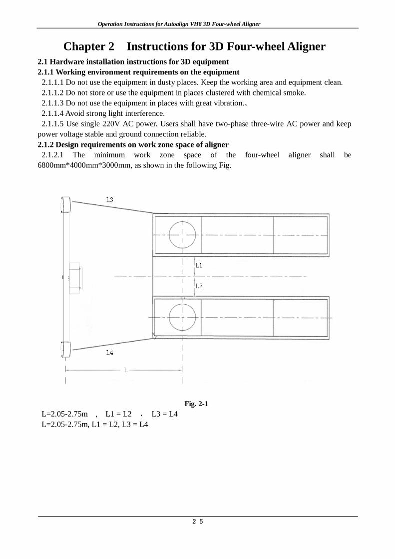
2.1.2.1 The minimum work zone space of the four-wheel aligner shall be 6800mm*4000mm*3000mm, as shown in the following Fig.
Fig. 2-1
L=2.05-2.75m , L1 = L2 , L3 = L4 L=2.05-2.75m, L1 = L2, L3 = L4

Operation Instructions for Autoalign VH8 3D Four-wheel Aligner
26
Fig. 2-2
(Remarks: The scissor lift is taken as an example in this Fig.)
2.1.3 Alignment platform requirements Common four-wheel alignment platform includes: alignment scissor lift, four-column lift, runway machine, trench, etc. It requires high precision in alignment. Therefore, the following items shall be highlighted during the construction of foundation: 2.1.3.1 The foundation concrete thickness shall be no less than 180mm; 2.1.3.2 Leave space for the tail of cylinder of runway lift; 2.1.3.3 Leave sufficient work space around the lift: respectively not less than 1000mm and 750mm; 2.1.3.4 Pay attention to the left and right installation positions of the electric control cabinet of the lift; 2.1.3.5 Whether the electric control cabinet is within the distance specified in the drawing (if excessive, oil pipe and air pipe shall be prolonged.); 2.1.3.6 Vehicle boarding direction on the installation foundation; and 2.1.3.7 Center distance between two wheels shall be about 1400mm, ±50mm. 2.1.4 Relative position of column video camera and lift platform of 3D four-wheel aligner 2.1.4.1 To ensure a better visual field of the video camera, a relative position is required between the camera lens and the lift platform, between the column and the platform. The cross range between lens and lift platform shall be within the scope of 1.8~2.5m, and the height difference from the surface of the alignment platform to the center of the camera shall be kept within 0.8~1m. 2.1.4.2 Aligner classification (as shown in the following Fig.)

Operation Instructions for Autoalign VH8 3D Four-wheel Aligner
27
Fig. 2-3

Operation Instructions for Autoalign VH8 3D Four-wheel Aligner
28
2.1.5 Basic installation steps of 3D aligner 2.1.5.1 Before installation, please check the goods carefully. See whether the outer package is damaged, the goods is complete or not according to the goods list. If anything abnormal occurs, please timely communicate with us for solution.
(Fig. 2-4 Wooden Packing of Beam)
(Fig. 2-5 Wooden Packing of Column)
(Fig. 2-6 Wooden Packing of Cabinet) (Fig. 2-7 Wooden Packing of Accessories)
2.1.5.2 After inspection, open the outer package of the equipment in sequence. 2.1.5.3 Take the column out of the wooden case; lay the column down with the place to lay the
column base chosen according to the actual installation place. 2.1.5.4.1 The G6 slide-rail column is assembled as follows: 2.1.5.4.1.1 Take out the column, adjust the slide-rail knob to make the slide-rail move to proper height and then screw down the knob.

Operation Instructions for Autoalign VH8 3D Four-wheel Aligner
29
Fig. 2-8
2.1.5.4.1.2 Move the beam out of the packing case; remove the packing at the joint in the middle; and connect the beam and the column with 4 M8 nuts respectively.
Fig. 2-9 Beam Diagram Only for Reference, Subject to the Real Object Fig. 2-10 Rear View of Slide-rail G6 2.1.5.4.1.3 Circuit connection 1: As for the connection of the control panel, connect the principal
harness with the control panel and the external line of the beam according to the circuit diagram in the control box. Connect the wires according to corresponding line No. with moderate plugging and unplugging strength.

Operation Instructions for Autoalign VH8 3D Four-wheel Aligner
30
(Fig. 2-11 Circuit Connection 1- Circuit Diagram of Control Panel)
(Fig.2-12 Circuit Connection 1- Internal Circuit Diagram of Control Panel) (Fig. 2-13 Circuit
Connection 1- Connection Plug of Control Panel)
(Fig. 2-14 Circuit Connection 1-Connection Lines of Control Panel) Circuit connection 2: As for the connection of the principal harness with the host and the power

Operation Instructions for Autoalign VH8 3D Four-wheel Aligner
31
source, it shall be done according to corresponding line No.
(Fig. 2-15 Circuit Connection 2-Host Interface)
Circuit connection 3: As for the connection of the ground lead, connect the host, beam, column and cabinet with the ground firmly and then connect the 10-meter ground lead with the ground pin from the ground terminal to ensure the close and firm connection with the ground of the ground pin for electrostatic discharge. (Refer to Grounding Operation Instructions for details)
Fig. 2-16
2.1.5.4.1.4 Install the column cap and slowly erect the column after completion. 2.1.5.4.1.5 Correctly install the cabinet. Take the cabinet out and clean it. Install the brackets of
four target boards on the cabinet. Then put such accessories as monitor, host, printer, keyboard and mouse onto corresponding positions of the cabinet. Install and arrange outer power source; and ensure that the voltage is stable and circuit is safe.

Operation Instructions for Autoalign VH8 3D Four-wheel Aligner
32
(Fig. 2-17 Interior Setting of Cabinet) (Fig. 2-18 Tray Structure)
(Fig. 2-19 Tray Installation) 2.1.5.4.2 Installation methods of internal filter: 2.1.5.4.2.1 Open the back door of the cabinet, find the white power plug connecting the multi-hole socket inside the cabinet with the main power line and pull out the white power plug of the cabinet. 2.1.5.4.2.2 Connect the white power plug at the input terminal of the filter with the main white power plug of the cabinet main power. 2.1.5.4.2.3 Connect the filter. 2.1.5.4.2.4 Connect the white power plug at the output terminal of the filter with the white input power plug of the multi-hole socket. 2.1.5.4.2.5 Open the power switch of the cabinet and the output voltage of the multi-hole socket is measured to be 220V by a multimeter. 2.1.5.4.2.6 Connect the electrical equipment. It is OK now.

Operation Instructions for Autoalign VH8 3D Four-wheel Aligner
33
Fig. 2-20 Methods of transforming the internal filter to the external filter: 1. Pull out the power plug at the input terminal of the filter. 2. Connect the white power plug at the input terminal with the white power plug at the output terminal of the filter. 3. Connect the external power line joint with the input terminal of the filter and the output voltage of the filter is measured to be 220V by a multimeter. Connect the plug at the output terminal of the filter with the power socket of the cabinet. It is OK now.
Fig. 2-21
2.1.5.4.3 Installation of electric column 2.1.5.4.3.1 Take the column out of the wooden case; lay the column down with the place to lay the
column base chosen according to the actual installation place; and tear down corresponding packing foam and stretch film.
Fig. 2-22 2.1.5.4.3.2 Move the beam out of the packing case; remove the packing at the joint in the middle;
and dismount the splint for fixing the counterweight.

Operation Instructions for Autoalign VH8 3D Four-wheel Aligner
34
Fig. 2-23 Before Removal 2.1.5.4.3.3 Mount the guide roller and fix it as is shown in the following Fig.
Fig. 2-24 After Removal
2.1.5.4.3.4 Connect the beam and the column with 4 M8 nuts respectively.
Fig. 2-25
2.1.5.4.3.5 Meanwhile, the middle parts of the beam shall be connected with the steel rope derived from the column. While connecting, mount the adapter on the transfer block of the beam and butt joint at the other end of the steel rope. Finally screw up the M6 bolt.

Operation Instructions for Autoalign VH8 3D Four-wheel Aligner
35
Structure of Single Steel Rope Structure of Double Steel Ropes
Fig. 2-26 2.1.5.4.3.6 The steel rope shall be straight and shall be in the guide way of the guide roller and capstan. Install the column cap and erect the column slowly after completion. See Fig. 2-49 (Affiliated Fig. 1 in Chapter 2) for the explosive diagram of columns. See Fig. 2-50 (Affiliated Fig. 2 in Chapter 2) for the overall grounding diagram.
Structure of Single Steel Rope Structure of Double Steel Ropes
(Fig. 2-27 Steel Rope Straightening)
Structure of Single Steel Rope Structure of Double Steel Ropes
(Fig. 2-28 Steel Rope Connection)

Operation Instructions for Autoalign VH8 3D Four-wheel Aligner
36
Structure of Single Steel Rope Structure of Double Steel Ropes (Fig. 2-29 Installation Structure on the Upper Part of Motor)
(Fig. 2-30 Manual Locking Device)
2.1.5.4.3.7 Circuit connection 1: Refer to 2.1.5.4.1 Circuit connection 1 for the connection of control panel. Circuit connection 2: Refer to 2.1.5.4.1 Circuit connection 1 for the connection of principal harness with the host and the power source. Circuit connection 3: Refer to 2.1.5.4.1 Circuit connection 1 for the connection of ground lead. Circuit connection 4:As for the connection of electronic control unit harness, the 3D harness shall be connected with the electronic control unit according to corresponding line No.
(Fig. 2-31 Circuit Connection 4-1 Connection Lines of Electronic Control Unit)
Circuit connection 4: When connecting the motor control harness, lead the small harness from the circular hole at the bottom of the cabinet in the cabinet and connect the harness according to corresponding line No.

Operation Instructions for Autoalign VH8 3D Four-wheel Aligner
37
(Fig. 2-32 Circuit Connection 4-2 Small Motor Control Harness Connection According to Corresponding Line No.) 2.1.5.4.4 Assembly of double- display machine 2.1.5.4.4.1 Refer to the assembly of slide-rail column for the assembly of short slide-rail; and refer to the assembly of electric column as for electric column. 2.1.5.4.4.2 Fix the auxiliary cabinet on the column. 2.1.5.4.4.3 Install the display on the auxiliary cabinet and fix it.
Fig. 2-33 Cabinet Diagram Only for Reference, Subject to the Real Object
Fig. 2-34 Dismounting of the Dead Plate of Display

Operation Instructions for Autoalign VH8 3D Four-wheel Aligner
38
Fig. 2-35 Installation of Display
2.1.5.4.4.4 Install the four trays of the target board on the column and then put the monitor, host, printer, keyboard and mouse onto corresponding positions of the cabinet. 2.1.5.4.4.5 Refer to 2.1.5.4.1 assembly of slide-rail column and 2.1.5.4.4 assembly of electric column for the circuit connection.
Fig. 2-36 Double-display Aligner

Operation Instructions for Autoalign VH8 3D Four-wheel Aligner
39
2.1.5.4.5 Assembly of all-in-one machine
Fig. 2-37
1. Install the trundles on the collet and pay attention to the position of the front and back trundles. The balancing trundle is in the back.
2. Install the cabinet on the collet and firm it with M8x60 bolt.
3. Install the column and beam assembly on the collet and fix it with M8x60 bolt carrying spring washer.
4. Open the front door of the cabinet, and insert the T-bolt into the slide-rail of the column from the reserved circular hole, as shown in the following Fig. Then fix it with flange nut.

Operation Instructions for Autoalign VH8 3D Four-wheel Aligner
40
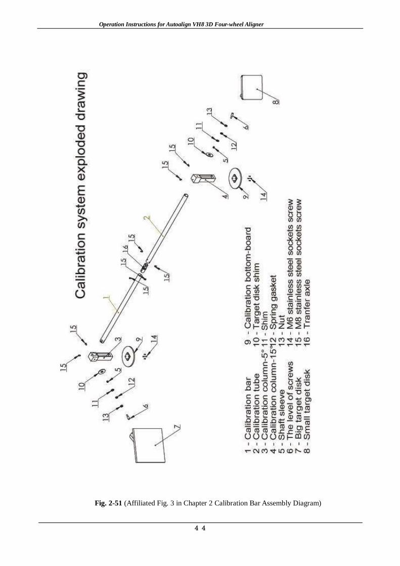
2.1.5.5 Standard assembly. Open the package, take out the components, and assemble the components according to the installation diagram. See Fig. 2-51 and 2-52 (Affiliated Fig. 3 and Fig. 4 in Chapter 2) for standard assembly.
Fig. 2-38 Outer Packing of Standard Assembly Fig. 2-39 Take out the Storage Box
Fig. 2-40 Calibration Base & Target Board Fig. 2-41 Calibration Bar
Fig. 2-42 Before Connecting the Calibration Bar Fig. 2-43 After Connecting the Calibration Bar
Fig. 2-44 Vertical View of Small Target Board after Connection Fig. 2-45 Vertical View of Big Target Board after Connection

Operation Instructions for Autoalign VH8 3D Four-wheel Aligner
41
Fig. 2-46 Nut Connection on the Target Board Diagram
Fig. 2-47 Diagram of Installed Calibration System 2.1.5.6 Installation of the target board used for measuring the vehicle height is only used for the most high-end model of 3D Aligner.
Fig. 2-48 Target Board Used for Measuring the Vehicle Height
2.1.5.7 Measure and find out the central line of the lift platform according to the site condition from the boarding direction; pick out the standing position for the column subject to the front end of the platform; ensure the flatness of the ground; and move the assembled columns and beams to the position. Please see 2.1.2 Diagram and 2.1.4 Graphic Size for details. 2.1.5.8 Raise the lift platform to required height and put the target disks in symmetrical way by the sequence of 0, 1, 2, 3 (i.e., left front-right front-left rear-right rear by the vehicle boarding direction). Put two small target disks on the turntable and two big target disks on the side sliding plate (or hang the target disks on the vehicle). Connect the power source of 3D aligner, log on alignment software and take the test of visual field. Adjust the beam and column to the optimal test position and use expansion screw to fix the column. 2.1.5.9 Place the cabinet at a proper position; and clean the alignment position and equipment. Wait until the vehicle is in position and take four-wheel alignment of the vehicle.

Operation Instructions for Autoalign VH8 3D Four-wheel Aligner
42
Fig. 2-49 (Affiliated Fig. 1 in Chapter 2 Explosive Diagram of Columns)

Operation Instructions for Autoalign VH8 3D Four-wheel Aligner
43
Fig. 2-50 (Affiliated Fig. 2 in Chapter 2 Ground Lead Diagram)
Operation Instructions for Autoalign VH8 3D Four-wheel Aligner
44
Fig. 2-51 (Affiliated Fig. 3 in Chapter 2 Calibration Bar Assembly Diagram)

Operation Instructions for Autoalign VH8 3D Four-wheel Aligner
45
Fig. 2-52 (Affiliated Fig. 4 in Chapter 2 Calibration Bar Assembly Diagram-Equipped with Ultrathin Target Board)

Operation Instructions for Autoalign VH8 3D Four-wheel Aligner
46
Chapter 3 Instructions for Software Installation Read this chapter to acknowledge the following: 1. Installation and debugging of software; 2. Features of 3D alignment software; and 3. The methods for installation and use of the alignment software. 3.1 Quick installation of four-wheel alignment software The first step: Installation of software Run setup.exe in the software folder Then click “Next” according to the tips. During the installation of software, it is recommended to follow the default parameters of software. The second step: Installation of database There are no database and maintenance data after installation. It is required to double click 3D General Chinese Installation Data to carry out the installation. The upgrading patch will automatically recognize the installation path of the software. Click “Next” to upgrade and select “Cover All” if the window “Cover all windows or not” pops up during the upgrading process till the end. The third step: Installation of the default value of the camera and the target board Copy the 6 files, namely, camera_data_0, camera_data_1, target_data_0, target_data_1, target_data_2 and target_data_3 provided by the manufacturer into the folder S3D3. As for the equipment with ride height measurement, it is required to copy target_data_9. The fourth step: Installation of equipment driver Finally, install the hardware driver of the equipment. Connect the communication cable, click <Computer> with the right-hand button, then click the <Nature>, and click <Device Manager> on the left side of the interface afterwards, as shown in the following Fig. There are 3 exclamation marks in the Fig., indicating the finished installation of the hardware device but abnormal situation of the equipment driver which needs to be installed additionally.
1. Right click the equipment with exclamation marks, as shown in the following Fig.;

Operation Instructions for Autoalign VH8 3D Four-wheel Aligner
47
2. Click <Update Driver Software>, as shown in the following Fig.:
3. Select the second item (marked with the red line) and click to display the <Browse>, as shown in the following Fig.:
4. Find the folder that contains drivers for the setting up of s3d software; select <drivers> and

Operation Instructions for Autoalign VH8 3D Four-wheel Aligner
48
click <OK> to finish the setting up. The three installation programs of the hardware drivers are of the same. After the installation is completed, return to the interface of <Device Manager>, the exclamation marks will disappear, as shown in the following Fig. The installation of all hardware drivers has been completed.
Notes: 1. This computer is used for four-wheel alignment only and shall not be used for other purposes to avoid mal-operation which may lead to system crash or deletion of this alignment system by mistake. 2. It is recommended to use win7 32 bit flagship version operation system, with the optimum resolution of 1360*768. 3. The default installation path shall be d:\S3D3. Please do not remove this folder to other places or delete it, which may cause abnormal starting of the system. 3.2 Specific modules & module functions of software There are two modules in the software, namely measurement and miscellaneous function. 1. Measurement function: The whole four-wheel alignment measurement is completed in this module. That is to say, you can complete the whole measurement process according to the steps of the program or perform a single project measurement according to the requirements of the client. 2. Miscellaneous function: Some relevant parameters of the equipment. 3.3 Software operation instructions After installation of software, double click the desktop icon to enter the system, and the following interface may appear. The program version and database version are shown on the upper left corner of the interface. After installation of software or data upgrading, you can check whether the software version and database version are correct.
Introduction to buttons:
Exit program;
Software using help;

Operation Instructions for Autoalign VH8 3D Four-wheel Aligner
49
System setup with all miscellaneous functions completed by this button;
Give up the last measurement data and start a new measurement;
Start a new measurement or continue the previous measurement when opening a new software.
3.3.1 Measurement function
Click the button on the main interface to start a new measurement on the next interface;
Introduction to buttons: Visual field of camera for checking whether the camera works normally or whether the target board is within the visual field of camera;
Add client or select the existing client;
Vehicle condition check for some relevant inspections of vehicle before alignment;
Vehicle model selection for choosing the vehicle type to be aligned;
Compensation measurement of pushing vehicle for the measurement of pushing vehicle;
King pin measurement for the measurement of kingpin after pushing vehicle;
Measurement result display interface for specific measurement of front wheel and rear wheel;
Extended functions to realize more functional measurements.
Notes: All functions may be skipped to enter the next function directly.
Add Client

Operation Instructions for Autoalign VH8 3D Four-wheel Aligner
50
3.3.1.1 Add client 3.3.1.1.1 Function Search and addition of client data 3.3.1.1.2 Specific operation
Add client: Input the client information and click to save the client data to enter the next vehicle condition inspection interface.
Notes: The button in the software has the function of saving information. Click
to save the data tacitly, and click or other buttons if the data is not required to save.
Client search: Click the client search button, and the following interface showing all the
clients having the alignment will appear. Select the required client and click to enter the Add Client Interface where the selected client information will be shown. If there is much client information shown in the historical data of client, you can use the search function. Input the relevant client information which can be any known client information, such as name, address and
phone, click , and then the found information will be shown in the left list. Choose the
client data to be printed, and click to print the historical data of client.
Historical Data of Client
3.3.1.2 Vehicle condition inspection 3.3.1.2.1 Function Inspect and record the vehicle condition. 3.3.1.2.2 Specific operation
Click on Add Client Interface or to enter the following interface directly:

Operation Instructions for Autoalign VH8 3D Four-wheel Aligner
51
Vehicle Condition Inspection_Tire Inspection
This interface shows tire inspection in the vehicle condition inspection. Please input detailed information according to the specific circumstance of vehicle.
Click to enter the alignment inspection in the vehicle condition inspection, as shown in the following interface:
Vehicle Condition Inspection_Alignment Inspection
Select detailed information according to the specific condition of vehicle.
Click to enter the additional inspection in the vehicle condition inspection, as shown in the following interface:

Operation Instructions for Autoalign VH8 3D Four-wheel Aligner
52
Vehicle Condition Inspection_Additional Inspection
Select detailed information according to the specific condition of vehicle.
All vehicle condition inspections may be skipped. Click to save the already done inspections and enter the next step. 3.3.1.3 Vehicle model selection 3.3.1.3.1 Function Select the vehicle model to be aligned. 3.3.1.3.2 Specific operation
Click on Vehicle Condition Inspection Interface or to enter the following interface directly:
Vehicle Model Selection
The left side is the brand list-box. Search according to the ranking of brands or click A, B, C, D……on the left side.
Operation Instructions for Autoalign VH8 3D Four-wheel Aligner
53
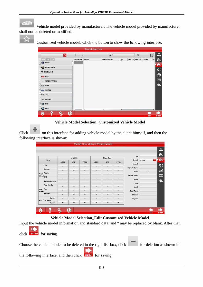
Vehicle model provided by manufacturer: The vehicle model provided by manufacturer shall not be deleted or modified.
Customized vehicle model: Click the button to show the following interface:
Vehicle Model Selection_Customized Vehicle Model
Click on this interface for adding vehicle model by the client himself, and then the following interface is shown:
Vehicle Model Selection_Edit Customized Vehicle Model
Input the vehicle model information and standard data, and ° may be replaced by blank. After that,
click for saving.
Choose the vehicle model to be deleted in the right list-box, click for deletion as shown in
the following interface, and then click for saving.

Operation Instructions for Autoalign VH8 3D Four-wheel Aligner
54
Vehicle Model Selection_Delete Customized Vehicle Model
Notes: The data added by the client himself will not support the VIN search function.
Common vehicle model: All vehicle models used by the client are listed here. On the main interface of the vehicle model selection, click the title in the right list-box, and then a
triangle mark is shown, such as . Click the triangle mark for ascending order or descending order.
Vehicle model search: Input the vehicle model to be searched on the upper left,Click to
search Vehicle model search by VIN code: Input the 17-digit VIN code of the vehicle or scan the VIN
code by a code scanner, and click to find the corresponding vehicle code of the VIN code. If some vehicle have one dimensional code rather than VIN code, please print the corresponding one dimensional code of the VIN code and paste it on the auto for directly finding the vehicle
model by scanning the code. After inputting the VIN code, click to print it.
Standard data: Click to enter the Standard Data Interface as follows:
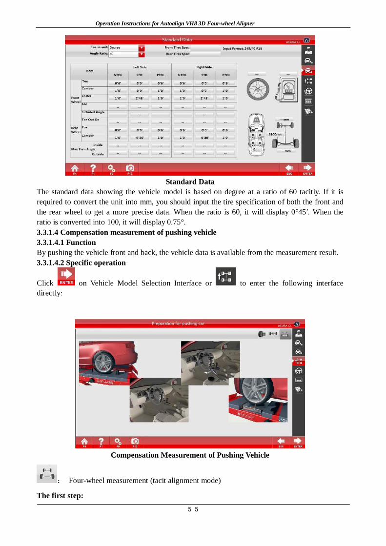
Operation Instructions for Autoalign VH8 3D Four-wheel Aligner
55
Standard Data
The standard data showing the vehicle model is based on degree at a ratio of 60 tacitly. If it is required to convert the unit into mm, you should input the tire specification of both the front and the rear wheel to get a more precise data. When the ratio is 60, it will display 0°45′. When the ratio is converted into 100, it will display 0.75°. 3.3.1.4 Compensation measurement of pushing vehicle 3.3.1.4.1 Function By pushing the vehicle front and back, the vehicle data is available from the measurement result. 3.3.1.4.2 Specific operation
Click on Vehicle Model Selection Interface or to enter the following interface directly:
Compensation Measurement of Pushing Vehicle
: Four-wheel measurement (tacit alignment mode)
The first step:

Operation Instructions for Autoalign VH8 3D Four-wheel Aligner
56
Play the animated cartoon to make preparation for pushing the vehicle, conduct the corresponding specific operation to ensure the turntable is bolted, put the transition gasket, stop the vehicle to the designated position, loose the brake fixer, lock the steering wheel fixer, and place a cushion
against the rear wheel of the vehicle to keep the vehicle stable. Afterwards, click to start the measurement.
Compensation for Pushing Four Wheels of Vehicle_1
The second step Remove the gasket. Following the arrow prompt, push the vehicle backwards firstly until the arrow turns green (as shown in Fig. 3-8), and then place a gasket the keep the vehicle stable to wait for the direction change of arrow; when the arrow reverses, push the vehicle to the position where the arrow turns green (as shown in Fig. 3-9) according to the tips, and then place a gasket the keep the vehicle stable to wait for the completion of the measurement. Notes: Such situations in the Compensation for Pushing Four Wheels of Vehicle_4 may appear in the process of measurement: 1. Wheel is shielded; 2. Shake exists in the process of pushing vehicle; 3. The vehicle is being pushed; 4. The vehicle is pushed out and needs pushing back; 5. The vehicle stops stably for waiting.
Compensation for Pushing Four Wheels of Vehicle_2

Operation Instructions for Autoalign VH8 3D Four-wheel Aligner
57
Compensation for Pushing Four Wheels of Vehicle_3
Compensation for Pushing Four Wheels of Vehicle_4
The third step If the wheel shakes abnormally during the measurement, then enter the interface of Compensation for Pushing Four Wheels of Vehicle_5. The part marked with a yellow triangle indicates the
specific shaking wheel. Click to go back to the Compensation for Pushing Four Wheels of
Vehicle_1 for re-measurement, and click to ignore the shaking and start the king pin measurement.
Notes: If abnormal shaking occurs, check whether the clamp of the calibration plate of corresponding wheel is loose or not. Adjust and re-measure. If directly return to the first step, there may be large deviation in the measurement data.

Operation Instructions for Autoalign VH8 3D Four-wheel Aligner
58
: Single-wheel measurement
By lifting the vehicle, respectively rotate the four wheels to measure the vehicle data. Land vehicle, and read the data from the measurement result. The first step Click the [Single-wheel Measurement] button in preparation for pushing vehicle compensation to enter the Single-wheel Measurement Interface.
Single-wheel Measurement_1
The second step
Lift the vehicle as instructed, and click to enter the wheel measurement selection interface.
Single-wheel Measurement_2
The third step Rotate corresponding wheels, and make the surface of its target board towards the camera and perpendicular to the ground. Select the wheel to be measured on the upper right corner of the above Fig, and then enter the single-wheel measurement interface; as the interface instructs, first

Operation Instructions for Autoalign VH8 3D Four-wheel Aligner
59
rotate the wheel backwards, then forwards until the completion of measurement. Return to the wheel measurement selection interface (Single-wheel Measurement_2). The fourth step When the measurement of the four wheels is completed, the single-wheel compensation is completed.
Notes: Only when the four-wheel alignment measurement is carried out by the pushing action due to ground restriction or other reasons can the function be used. Moreover, the single-wheel measurement function can be completed only when the integrated four-wheel measurement is completed. If the integrated single-wheel measurement or four-wheel measurement has been done, but the target board of an individual wheel deviates, the individual wheel can be measured by the single-wheel measurement function. Measurement preparation interface;
: Double-wheel measurement
The measurement is based on the two target boards of the front wheels, and the measurement method is similar to the four-wheel measurement. 3.3.1.5 King pin measurement 3.3.1.5.1 Function By turning left and right, measure the data of king pin, toe-out and max. steering angle of the vehicle. The data can be read from the measurement result. 3.3.1.5.2: Specific operation
Click on measurement of compensation for pushing vehicle interface or to enter the following interface directly: The first step Ensure that the turntable is bolted, stop the vehicle to a specified position, and place a cushion against the rear wheel of the vehicle to keep the vehicle stable to enter the king pin measurement interface.
The second step

Operation Instructions for Autoalign VH8 3D Four-wheel Aligner
60
As shown in the animated cartoon on the preparation interface, brake the vehicle stably, remove
the bolt of turntable, install the brake holder, and click to start the measurement, as shown in the Fig. The numbers in the Fig. represents: ①Attribute block for the item to be measured at present ②Slide block for direction and angle ③④ King pin measurement position ⑤⑥ Measurement position of toe-out angle ⑦ indicating to turn left ⑧Indicating to turn right ⑨The wheel is covered ⑩Reading the angle of steering wheel
The third step The measurement can be done by five steps. As shown in the king pin measurement interface, turn left to ③, stabilize and wait after the corresponding picture changes to green; next, turn left to ⑤ and then go on turning left until the steering wheel doesn’t move, stabilize and wait until the picture turns green; turn right, stabilize and wait; turn right to ④, stabilize and wait; then turn right to ⑥, stabilize and wait; go on turning right until the steering wheel doesn’t move, stabilize and wait until the photo turns green; at last, turn to the middle and the angle stays within ±0°6'. Avoid the camera passage and finish the measurement, and automatically enter the Measurement Result Interface. If the wheel shakes, enter the Re-measurement Interface.

Operation Instructions for Autoalign VH8 3D Four-wheel Aligner
61
Click to go back to King Pin Measurement_1 for re-measurement, and click to ignore shaking.
Notes: As is shown in King Pin Measurement_1 of the measurement interface, after the measurement of ③ or ④, ⑦⑧ will occur at the same time. Now, turn to another direction and omit the measurement of ⑤⑥. If abnormal shaking occurs, check whether the fixture of calibration plate of corresponding wheel is loose or not, the brake is tight or not. Adjust them and re-measure. If directly return to the first step, there may be large deviation in measurement data. 3.3.1.6 Measurement result 3.3.1.6.1 Function: Check the measurement data of the vehicle with the function of real-time adjustment. 3.3.1.6.2 Specific operation:
Click on king pin measurement interface or to enter the following interface directly:
Measurement Result
Standard data: It shows the standard data of the measured vehicle;
Lift-up measurement: Measure the lift-up vehicle;
Save before adjustment: Save the data before adjustment;
Save after adjustment: Save the data after adjustment;
Print: Print the measurement data;
Rear-wheel adjustment: Real-time adjustment of rear wheel;
Front-wheel adjustment: Real-time adjustment of front wheel;

Operation Instructions for Autoalign VH8 3D Four-wheel Aligner
62
King pin adjustment: Real-time adjustment of king pin; All measured alignment data are shown on the interface of measurement result. Put the mouse on the photo near the measurement data, and the name of the measurement item will appear; The base background of the measurement data has different colors, in which green
indicates the measurement data is in the standard scope, red
indicates the measurement data is beyond the standard scope, and gray indicates the measurement data is nonadjustable.
Rear-wheel Measurement
Front-wheel Measurement

Operation Instructions for Autoalign VH8 3D Four-wheel Aligner
63
Caster Measurement
Print the Report_Alignment Data Print the Report_2 Vehicle Condition Data
Notes: The [Save] button before measurement should be used after finishing four-wheel and king pin measurement. It is not allowed to use it after vehicle adjustment; otherwise, the measurement data before adjustment will be overwritten. To enter the Measurement Result Interface, if the steering wheel angle exceeds ±12', it is required to enter the Steering Wheel Adjustment Interface first. After adjusting the steering wheel, it will automatically enter the Measurement Result Interface. Or click [Enter] to enter the Measurement Result Interface directly without adjustment. 3.3.1.7 Extended functions
Click on measurement result interface or to enter the following interface directly:

Operation Instructions for Autoalign VH8 3D Four-wheel Aligner
64
Extended Functions
Tire-dismounting Adjustment: It is matched with special rim adapter to realize the real-time displaying of the angle variation when dismounting the tire and adjusting the camber angle. Rim adapter: It is a kind of target disk connection device for tire-free installation after the tires are dismounted. Click [Tire-dismounting Adjustment] button to enter the Tire-dismounting Adjustment Interface:
Removing Tire Adjustment_1
Lift the vehicle, and dismount the tires according to the tips, install the rim adapter and the
clamps, and click after the operation is completed to enter the Rear-wheel Adjustment
Interface (rear-wheel measurement); afterwards, click to enter the Front-wheel Adjustment Interface (front-wheel measurement);and return to Interface 3-15 after the calculation is completed. The front-wheel adjustment or rear-wheel adjustment can be carried out according to the position of the tire to be adjusted. After the adjustment is completed, click

Operation Instructions for Autoalign VH8 3D Four-wheel Aligner
65
again to enter the following interface:
Removing Tire Adjustment_2
Carry out the operation according to the tips.
Vehicle Dimension Measure the tread, wheelbase and the like of the vehicle. Click the [Vehicle Dimension] button to enter the Vehicle Dimension Interface after the
measurement of compensation for pushing vehicle, then the data will be shown.
Body Dimension
Click to return to the Extended Functions Interface and save the data, and click to return to the Extended Functions Interface without saving the data.
Steering Wheel Adjustment Keep the steering wheel straight according to the actual situation of the vehicle, and click the [Steering Wheel Adjustment] button to display the following Fig.:

Operation Instructions for Autoalign VH8 3D Four-wheel Aligner
66
Steering Wheel Adjustment There are angle value of the steering wheel and the toe-in values of the left and right front wheels in the interface. Adjust the toe-in value to the normal range according to the tips of the computer, and finished the process till the angle value of the steering wheel is 0.
Engine Bracket Adjustment As for the vehicle with the function, by the movement of the engine bracket to adjust corresponding angles, the function can guide the movement direction required by the engine bracket and display the measurement value of the steering axis inclination. Click the [Engine Bracket Adjustment] button, and the following Fig. will be displayed:
Engine Bay Adjustment_1
Brake the vehicle stably, remove the bolt of the turntable, click according to the tips, and then the following Fig. will be displayed:

Operation Instructions for Autoalign VH8 3D Four-wheel Aligner
67
Engine Bay Adjustment_2
Adjust the king pin to make the difference between the left and right steering axis inclination
angle within the reasonable scope. After the adjustment is completed, click , and then the following Fig will be displayed to set down the vehicle. .
Engine Bay Adjustment_3
Toe-in curvature Measurement The toe-in constant value of the vehicles (such as Passat B5 and Audi A6) with this function, namely the difference between the toe-in value after the suspension is lifting up by 60mm and the normal toe-in value can be measured. Click the [Toe-in curvature Measurement] button, and the following Fig. will be displayed:

Operation Instructions for Autoalign VH8 3D Four-wheel Aligner
68
Toe curvature Measurement_1
Install the B5 tools according to the tips to lift up the vehicle body by 60mm, and click after completion to enter the next interface:
Toe curvature Measurement_2
Click to set down the vehicle according to the tips.
Toe-in Lock Adjustment As for some vehicle, for the convenience of adjusting the toe-in, it requires to carry out the adjustment after turning the steering wheel to an extreme position. This function is to lock the toe-in value, and turn the steering wheel to a proper position for the convenience of adjusting the toe-in. Click the [Toe-in lock Adjustment] button, and the following Fig. will be displayed:

Operation Instructions for Autoalign VH8 3D Four-wheel Aligner
69
Lock Toe Adjustment_1
Keep the steering wheel straight according to the tips, and click after completion to enter the next interface:
Lock Toe Adjustment_2
After adjusting the steering wheel to a position that is convenient to adjust the toe-in, click
:

Operation Instructions for Autoalign VH8 3D Four-wheel Aligner
70
Lock Toe Adjustment_3
Carry out the adjustment in the interface, and click after the adjustment is completed.
After the adjustment is completed, turn the steering wheel to the straight position, and click to complete the adjustment.
Zero Toe-in Camber Measurement When the toe-in is zero, the camber value of the wheel will be displayed. The function is suitable for the vehicles with large kingpin caster angle. Click the [Zero Toe-in Camber Measurement] button, and then the following Fig. will be displayed:
Zero Camber Toe Measurement_1

Operation Instructions for Autoalign VH8 3D Four-wheel Aligner
71
Zero Camber Toe Measurement _2
Then, adjust the other front wheel to the zero toe-in position, and measure the camber of the front wheel.
Rolling Radius To measure if the tire size of the vehicle are matched. When the alignment process is completed, the rolling radius of each wheel can be displayed to remind the operator if the wheel models are matched or problems such as unequal wheel pressure or serious tire wear. Click the [Rolling Radius] button, and then the following Fig. will be displayed:
Rolling Radius
Tire Scrub Radius It aims to accurately measure the offset value of the front wheel, and to display the measurement value of the included angle, the steering axis inclination angle and the wheel camber. Definition of the tire scrub radius: also named as offset distance, is the distance from the intersection point between the tire center line and the ground to the intersection point between the kingpin extension line and the ground (as is shown in the following Fig.). If the intersection point between the kingpin extension line and the ground is inside the intersection point between the center line of

Operation Instructions for Autoalign VH8 3D Four-wheel Aligner
72
the tire and the ground, it is called as positive offset; otherwise, it is called as negative offset. It is required to alter the width data of the tire according to the real width of the tire, and carry out the push vehicle measurement again after the alteration. Click the [Tire Scrub Radius] button, and then the following Fig. will be displayed:
Tire Scrub Radius
Vehicle Height To accurately measure the height of the vehicle body, if you select the special target disk measurement, just point the special target disk pointer at the position to measure the vehicle. Function: As for the vehicles with adjustable suspension height, the adjustment can be carried out according to the measurement result; and as for the vehicles with air suspensions, suitable standard alignment data can be selected according to the measurement result. Click the [Vehicle Height] button, and then the following Fig. will be displayed:
Body Height_1
In this interface, select the position need to measure the vehicle height, and click to enter

Operation Instructions for Autoalign VH8 3D Four-wheel Aligner
73
the next interface:
Body Height_2
Select the measurement method to carry out the measurement. 3.3.2 Auxiliary function
Click the [System Setup] button on any interface, and then the following interface will be displayed:
System Settings
3.3.2.1 Parameter setup : As for relevant setup of the equipment model, configuration, password, etc., click the [Parameter Setup] button to enter the Parameter Setup Interface, as shown in the following Fig.:

Operation Instructions for Autoalign VH8 3D Four-wheel Aligner
74
Parameter Settings
The content of the equipment setup has been set up before ex-work. No recommendation of alteration is made for users. Password setup can be altered as required by the users. The angle unit can adopt degree or point; the toe-in can adopt the same displaying way as that of the camber or mm, but when mm is adopted for displaying, the tire diameter shall be altered according to the actual situation of the tire, otherwise, there will be errors in the measurement results.
Click to save the modified information, and click to exit the Parameter Setup Interface without saving the modified information.
3.3.2.2 User’s information : Record the detailed information of the automobile maintenance company which buys the equipment so that the users need vehicle alignment can contact the automobile maintenance company. Click the user’s information and then the user’s information entry interface will be displayed:
User Information
After the completion of input, click to save the modified information, or click to exit without saving the modified information.

Operation Instructions for Autoalign VH8 3D Four-wheel Aligner
75
3.3.2.3 Registration : The function shall be used after the software installation for the first time or re-installation of the operation system. Click the [Registration] button, as shown in the following Fig.:
Registration
Send the User ID to the equipment supplier to get the license number, and then click to
save the modified information after input, or click to exit the Registration Interface without saving the modified information. If the software can be normally applied, please do not operation the interface to avoid the software locking due to mal-operation. The functions of client management and vehicle model management are same to the previous ones. It is not recommended for the user to independently operate the equipment calibration and examination functions, so it is not introduced here.
Chapter 4 Application Precautions & Maintenance of Four-wheel Aligner Read this chapter to acknowledge the following: 1. Application precautions for each part of 3D aligner; 2. Maintenance, fault diagnosis & troubleshooting of aligner. 4.1 Application precautions & maintenance of target disk 4.1.1 Keep the surface of target disk clean. Use soft dry cloth to wipe it and avoid surface scratch. 4.1.2 The relative fixed position between the target disk and pylon is prohibited to be altered. Keep the surface of the target disk clean. Use soft dry cloth to wipe it and avoid surface scratch.
Use the target disk with the handle gently. Don’t touch the surface of the pattern and avoid
water and oil. Oil permeation will affect the use.

Operation Instructions for Autoalign VH8 3D Four-wheel Aligner
76
4.2 Application precautions & maintenance of computer 4.2.1 Please do not switch on the power switch or reset switch in the operation state of the computer, otherwise, it is possible to damage the software and hardware systems; 4.2.2 All defaults are set according to the hardware features and functional requirements of the computer by the Company. Please do not modify any settings in BIOS of the operation system to avoid any impacts on the normal operation of the computer; 4.2.3 Do not use the computer for any non-four-wheel alignment operation, such as watching VCD, listening CD or playing games to avoid the improper software installation, which may result in operation system failure or system breakdown due to virus strikes; if system expansion is required, please contact the manufacturer in time; 4.2.4 Hot plugging of serial port equipment, parallel port equipment, keyboard or other I/O equipment shall be prohibited; and 4.2.5 It is required to keep the computer clean and avoid any impacts of static electricity on the hardware equipment.
Notes: Please well keep the instructions attached, driver (disc) and warranty card of the computer! 4.3 Pylon maintenance The mechanical part is an integral part of the four-wheel aligner. It needs to ensure the integrity and flexibility of the pylon. Therefore, following points shall be guaranteed during usage: A. The pylon shall not be damaged, broken or deformed; B. If the top of the pylon has serious wearing, please timely replace it to avoid scratching the wheel rim; C. Regularly lubricate the screw rod and sliding bar to ensure the flexibility. (Fig. 4-2); D. Regularly fasten each connecting bolt. E. Handle with the pylon lightly. If unused, put it on the bracket and keep it well to avoid damage which may influence measuring accuracy and equipment life.

Operation Instructions for Autoalign VH8 3D Four-wheel Aligner
77
Fig. 4-2 Pylon 4.4 Turntable maintenance The maintenance of turntable mainly includes periodic cleaning, lubrication and fastening treatment. Method: Turn over the turntable with the upper wall facing down; disassemble the fixing bolt; remove the finger, grillage frame and foot wall respectively; clean the upper wall and foot wall, grinding shelf and ball bearing; install all parts in sequence after the ball bearing is covered with lubricating grease; and then fasten the erection bolt (Fig. 4-3). If the finger is loose, the fastening bolt must be fastened (Fig. 4-4). Before the vehicle is driven onto the alignment platform, the turntable lock pin shall be inserted. Before the front wheel moves away from the turntable, the vehicle shall be slowly pushed down from the platform to prevent the upper wall structure being damaged.
(Appearance of the Cast Iron Turntable) (Two-part Disassembly of Cast Iron Turntable)

Operation Instructions for Autoalign VH8 3D Four-wheel Aligner
78
(Disassembly of Steel Plate Turntable) (Appearance of Steel Plate Turntable)
(Two-part Disassembly of Steel Plate Turntable) (Steel Plate Turntable Roto)
(The retainer needs regular cleaning or replacement, as shown in the Fig.)
High-end Alloy Turntable Special Transition Block 4.5 Column body maintenance The column body of the lifting column requires regular cleaning and lubricating.
Notes: Under normal service condition, users may call us to consult any faults related to the equipment or our company may appoint personnel to deal with the faults. The so-called faults under normal service condition refer to the natural damages occurring under normal service condition without any deliberate faults or negligence of general users: i.e., unnatural wear and tear caused not due to mis-operation by users, dismantling by users or overhaul.