Embed Size (px)
Citation preview

1 | P a g e

FULL FORMS
CADD – Computer aided design & drafting
CAD – Computer aided design
CAM – Computer aided manufaturing
CAE – Computer aided engineering
ISO – International standard organization
MCAD – Mechanical CAD
CNC – Computer numeric control
VMC – Vertical machining center
Dxf – Data exchange format
IGES – International graphics exchange specification
By using CADD we can make drawing:
Quick
Accurate
Neat & clean
Highly presentable
Highly precision
2 | P a g e

AutoCADAutoCAD, developed by Autodesk
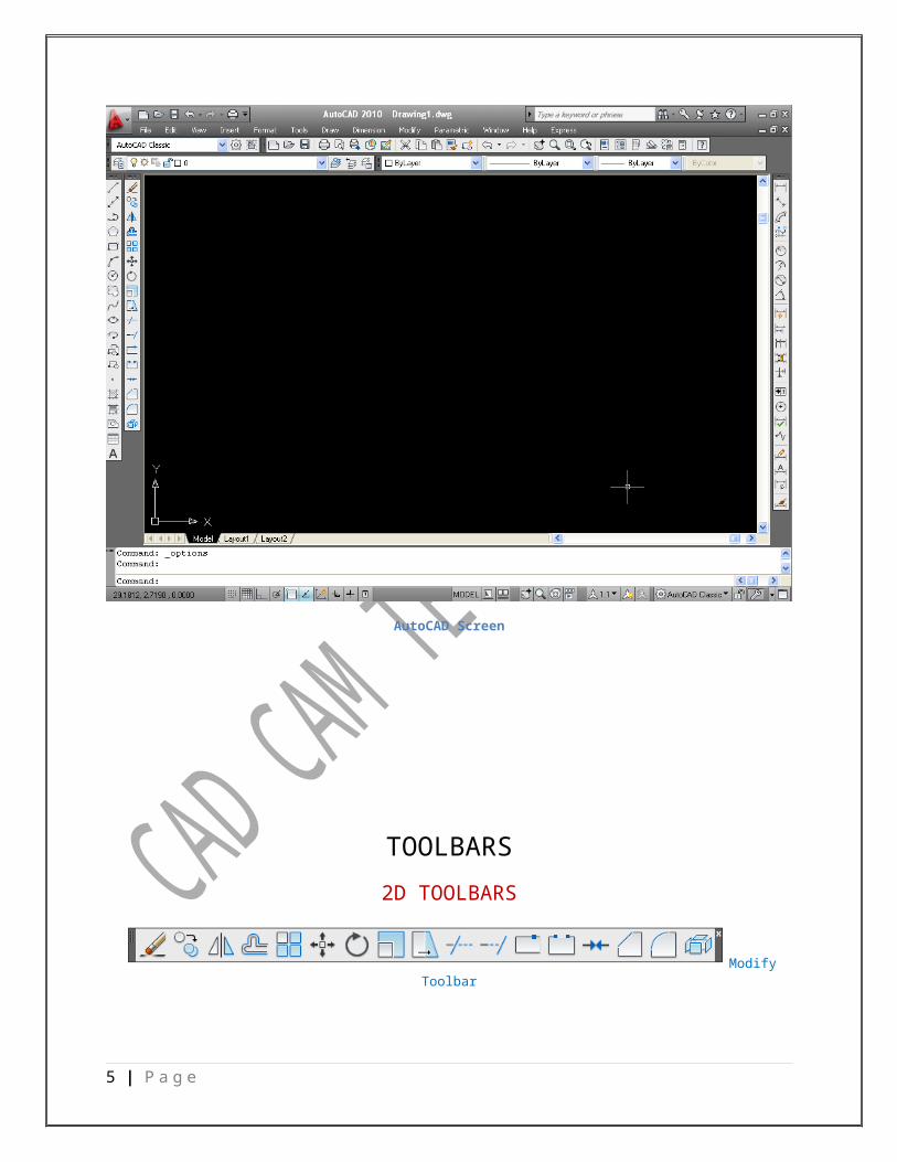
AutoCAD Screen
Various components of the initial AutoCAD screen are drawing area, command window, menu bar, several toolbars, model and layouts, and the status bar. A title bar that has AutoCAD symbol and the current drawing name is displayed on top of the screen.
AutoCAD Screen
3 | P a g e

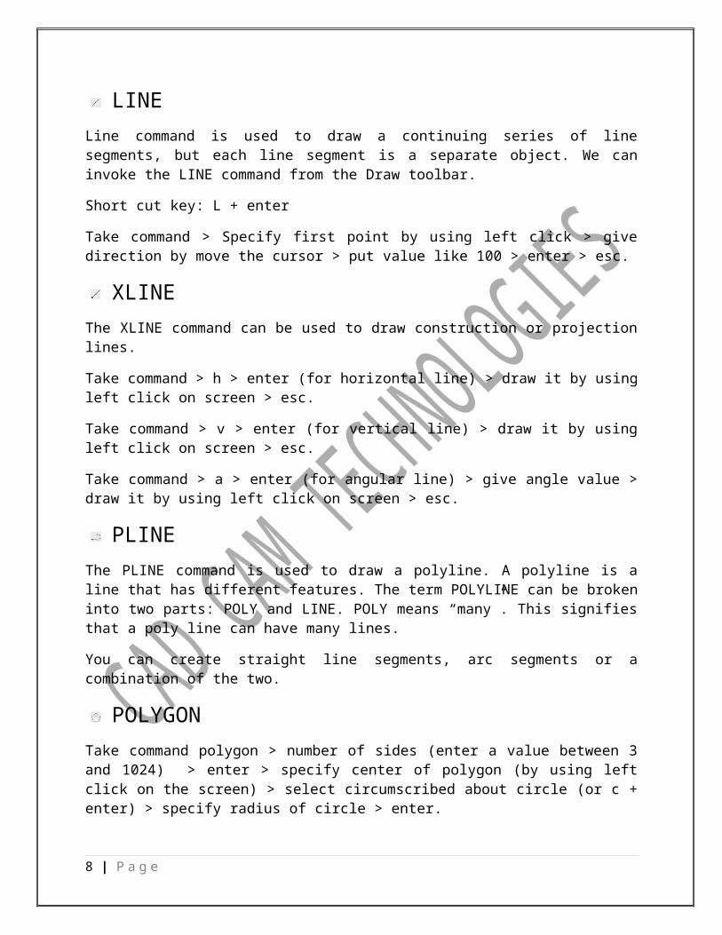
TOOLBARS
2D TOOLBARS
Modify Toolbar
Draw Toolbar
Dimension Toolbar
Layers Toolbar
Properties Toolbar
3D TOOLBARS
Modeling Toolbar
Orbit Toolbar
Solid Editing
UCS Toolbar
View Toolbar
4 | P a g e
Visual Style Toolbar
PAGE SETUP
Format > units > insertion scale > select unit >inches/cm/mm (according to requirement) > ok
Format > drawing limits > specify lower left corner > put limits 0,0 > enter > specify upper right corner > put limits like 1000,1000 > enter
Format > dimension style > modify > symbols and arrows > arrow size > put value like 2 (according to requirement) > ok
Modify > text > text height > put value like 2 (according to requirement) > text alignment > iso standard > ok
Modify > primary units > precision > take precision according to requirement > ok > set current > ok
View > zoom > all.
OR
We can use default page:
Acadiso
File > new > acadiso > open
5 | P a g e

COMMANDS
LINE
Line command is used to draw a continuing series of line segments, but each line segment is a separate object. We can invoke the LINE command from the Draw toolbar.
Short cut key: L + enter
Take command > Specify first point by using left click > give direction by move the cursor > put value like 100 > enter > esc.
XLINE
The XLINE command can be used to draw construction or projection lines.
Take command > h > enter (for horizontal line) > draw it by using left click on screen > esc.
Take command > v > enter (for vertical line) > draw it by using left click on screen > esc.
Take command > a > enter (for angular line) > give angle value > draw it by using left click on screen > esc.
PLINE
The PLINE command is used to draw a polyline. A polyline is a line that has different features. The term POLYLINE can be broken into two parts: POLY and LINE. POLY means “many”. This signifies that a poly line can have many lines.
You can create straight line segments, arc segments or a combination of the two.
POLYGON
Take command polygon > number of sides (enter a value between 3 and 1024) > enter > specify center of polygon (by using left click on the screen) > select circumscribed about circle (or c + enter) > specify radius of circle > enter.
6 | P a g e

Take command polygon > number of sides (enter a value between 3 and 1024) > enter > specify center of polygon (by using left click on the screen) > select inscribed in circle (or i + enter) > specify radius of circle > enter.
Take command polygon > number of sides (enter a value between 3 and 1024) > enter > e enter > specify first endpoint of edge > specify second endpoint of edge > enter.
RECTANG
Take command RECTANG > Specify first corner point (by using left click) > d + enter > length enter (horizontal) > width enter (vertical) > left click.
7 | P a g e
Rectangle with chamfer
Take rectang command > right click > chamfer > put chamfer dimentions > give rectangle start point (by using left click) > d + enter > give length > give width > enter > left click on screen.
Rectangle with fillet
Take rectang command > right click > fillet > put fillet radius dimention > give rectangle start point (by using left click) > d + enter > give length > give width > enter > left click on screen.
ARC
An arc is defined as a part of a circle. In AutoCAD, it can be drawn using the ARC command. AutoCAD provides eleven different options to draw an arc. To view these options, click on Draw option in the Menu Bar, a flyout option will appear as shown in fig. below
Options in Menu Bar for Creating an Arc
8 | P a g e

Take command ARC > Specify start point of arc > Specify second point > Specify the end point.
CIRCLE
The CIRCLE command is used to draw circles. AutoCAD provides six different options to draw a circle. To view and choose from the available options, click on Draw option in the Menu Bar, a flyout will appear as shown in fig. below
Options in Menu Bar for creating a Circle
Take command CIRCLE > click on screen to specify center point for circle > put the value of radius directly > enter.
Or
Take command CIRCLE > click on screen to specify center point for circle > d + enter > put the value of diameter > enter.
REVISION CLOUD
Take command > a + enter > specify minimum arc length ( like value 10) > specify maximum arc length ( like value 12) > O + enter > click on object > enter
9 | P a g e

Take command > a + enter > specify minimum arc length ( like value 10) > specify maximum arc length ( like value 12) > O + enter > click on object > y+ enter
SPLINE
Create a smooth curve that passes through or near specified points.
Take command > specify first point by using left click > specify next point > specify next point according to requirement > triple enter (i.e. enter enter enter).
ELLIPSE
If a circle is observed from an angle, the shape is called an ellipse, which can be created in AutoCAD using the ELLIPSE command. An ellipse can be created by two different options and these options are grouped together in the Draw option of the Menu Bar.
Command: ELLIPSE > Enter
Take command > Specify axis endpoint of ellipse by using left click of mouse > Specify other endpoint of axis by entering value like 100 > Specify the half length of second axis.
ELLIPSE ARC
Create an elliptical arc.
MAKE BLOCK
Take command > select object > right click > pick point > take base point > give name > ok.
10 | P a g e

INSERT BLOCK
Insert a block or a drawing into the current drawing.
POINT
Create multiple points.
HATCH
Take command > add pick point > pick internal point by using left click > right click > enter > select pattern > ok
GRADIENT
Same as hatch with colours.
REGION
This command is used for converting the relation of LINE into POLYLINE. Before using this command the sketch should be closed from all sides.
Take command > select all lines > right click.
EXPLODE
This command is used for converting the relation of POLYLINE into LINE.
Take command > select the POLYLINE or closed object > right click.
ERASE
To erase objects from drawing, we can use ERASE command.
Take command > Select object > Enter
COPY
The COPY command is used to copy an object at a specified distance in a specified direction.
Take command > Select objects to copy > right click > take base point > use it by clicking.
COPY WITH BASE POINT
Copy a drawing in a new window.
Select object > right click > copy with base point > take base point > go into new window > right click > paste > left click.
11 | P a g e

MIRROR
The MIRROR command creates a mirror copy of the selected object.
Take command > Select objects to be mirrored > Specify first point of mirror line by using left click > Specify second point of mirror line > enter.
Delete source objects? [Yes/No] <N>: Enter Y for deletion, N for retaining the objects.
OFFSET
To draw parallel lines, concentric circles, arcs, curves, and so on, we can use the OFFSET command.
Take command > give distance value > enter > select object > use it by clicking.
ADVANCED OFFSET
Take command > e + enter > erase source object after offsetting > select yes > give distance value > enter > select object > use it by clicking.
ARRAY
An array is used to creating multiple copies of the selected object and arranging them in a rectangular or circular fashion.
RECTANGULAR ARRAY
Rectangular Array option in Array dialog box
Take command > rectangular array > click on select object > select object > right click > give no.s of rows and columns > offset distance > ok.
12 | P a g e

POLAR ARRAY
Polar Array option in Arrray dialog box
Take command > polar array > click on select object > select object > right click > center point
(click on image) > take center point > give no.s of items > ok.
MOVE
This command used to move objects from their current location to a new location.
Take command > select object > right click > take base point > move object.
ROTATE
This command used to rotate objects from their current location to a specific angle.
Take command > select object > right click > take base point > put angle value > enter.
Advanced rotate or rotate with copy:
Take command > select object > right click > take base point > c + enter > angle value + enter.
SCALE
Enlarge or reduce selected object, keeping the properties of the object same after scaling.
Take command > select object > take base point > put value(like I want 2 times or 0.5 times) + enter.
13 | P a g e

STRETCH
This command used to stretch the objects from the selected base point.
Take command > select object with green window > right click > take base point > put value > enter.
TRIM
This command used to trim the objects from the selected side.
Take command > right click > use it.
EXTEND
With the use of this command, we can increase the line upto the specific point or location.
Take command > right click > use it.
BREAK AT A POINT
With the use of this command, we can break the line at a point where we required. Closed object such as circle cannot be broken at a single point.
Take command > select object like line > click at that point where you want to break.
BREAK
With the use of this command, we can break the line with a specific distance or upto a specific point as much we required.
Take command > select object (when we select object it take first point) > specify second point.
JOIN
Join similar objects to form a single, unbroken object.
Take command > select first line > select second line > right click.
CHAMFER
This command is used for removing the sharp corners.
Take command > a + enter > put value (like 10) + enter > angle value (like 45º) + enter > click on first line > click on second line.
14 | P a g e

Distance – distance chamfer :
Take command > d + enter > first value + enter > second value + enter > click on first line > click on second line.
Advanced chamfer:
Take command > a + enter > dimension + enter > angle value + enter > t + enter (select trim or no trim) > click on first line > click on second line.
FILLET
This command is used for removing the sharp corners.
Take command > r + enter > radius value (like 10) + enter > click on first line > click on second line.
Advanced fillet :
Take command > r + enter > radius value + enter > t + enter (select trim or no trim) > enter > click on first line > click on second line.
TABLE
15 | P a g e
![Command Quick Guide R12 – 2005 Related …€¦ · AutoCAD Productivity AutoCAD Command Quick Guide Appendix [ ] - 21 Notes: ... VLISP VPCLIP VPLAYER VPMAX VPMIN](https://img.pdfslide.net/doc/110x75/5b8f184909d3f2b01e8be368/command-quick-guide-r12-2005-related-autocad-productivity-autocad-command.jpg)


![Ashish Kumar, Rakesh Rai, Prasanna Seshadri, Amit Sowani · Ashish Kumar, Rakesh Rai, Prasanna Seshadri, Amit Sowani Special Notes: None. 1. Simple Loop [Ashish Kumar] (4 points)](https://img.pdfslide.net/doc/110x75/5f06625b7e708231d417b9c5/ashish-kumar-rakesh-rai-prasanna-seshadri-amit-sowani-ashish-kumar-rakesh-rai.jpg)