Embed Size (px)
Citation preview

�
AutoCAD orAutoCAD Mechanical 2004?A Productivity Study
www.autodesk.com/autocadmech 1
AutoCAD Mechanical 2004
ContentsIntroduction...............................................................................................................2
Workflow Productivity Comparison ................................................................................2
AutoCAD Mechanical Versus AutoCAD .........................................................................2
Before We Begin......................................................................................................3
Layer Management ..................................................................................................4
Hidden-Line Removal ...............................................................................................5
Detail View Creation.................................................................................................6
Hole Chart ..............................................................................................................7
Dimension Editing....................................................................................................7
Holes and Projected Views ........................................................................................8
Sprocket and Chain System.......................................................................................9
FEA Calculations ....................................................................................................10
Part Balloons.........................................................................................................11
Part Information and Parts List ................................................................................12
Summary*............................................................................................................13
Commonly Used Functions for 2D Design .....................................................................13
Centerline Creation ................................................................................................14
Automatic Dimensioning .........................................................................................14
Construction Lines .................................................................................................14
Mechanical Symbols ...............................................................................................15
Engineering Calculations .........................................................................................15
Standard Parts ......................................................................................................17
Functionality Comparison...........................................................................................18
Appendix.................................................................................................................19
Sharing Data in Different Languages.........................................................................19
Moving to the Mechanical Structure Environment........................................................19
Using 2D Mechanical Structure.................................................................................20
Productivity Study
AutoCAD Mechanical 2004 Productivity Study
www.autodesk.com/autocadmech 2
IntroductionMore than 20 years after the first release of AutoCAD® software, designers are still drawinglines and circles to represent mechanical parts. However, when discussing the contents of amechanical design drawing, designers typically refer to drawn items as assemblies, parts,holes, and possibly even motion. They rarely refer to the contents as lines or circles.AutoCAD® Mechanical 2004 provides design tools that enhance the 2D design experienceand offer a simpler, more natural 2D manufacturing design solution that more closelyresembles the way designers approach their work. This document provides details on thesedesign tools and demonstrates the productivity gains they provide over traditional AutoCAD.
The performance results in this paper were achieved by conducting automation testing overa controlled network. One engineer, with expert-level experience using both AutoCAD andAutoCAD Mechanical software programs, conducted the comparative tests on the samesample using an IBM® ThinkPad® A31 with a 2 GHz Intel® Pentium® 4 processor and 1 GBRAM. Results are approximate and subject to change. Product information and specificationsare subject to change without notice. Autodesk provides this information “as is,” withoutwarranty of any kind, either express or implied.
Workflow Productivity ComparisonBased on AutoCAD technology and the DWG format, AutoCAD Mechanical takes advantageof the latest improvements to AutoCAD 2004 to help you
• Create with speed
• Share with ease
• Manage with efficiency
AutoCAD Mechanical is a purpose-built 2D mechanical design system that features
• Intelligent mechanical engineering and design
• Associative production drawing and detailing
• Standards-based 2D content
AutoCAD Mechanical Versus AutoCADThis study explores 10 common design tasks, showing how the innovative, new 2D designtools in AutoCAD Mechanical 2004 offer significant productivity gains over standardAutoCAD software.
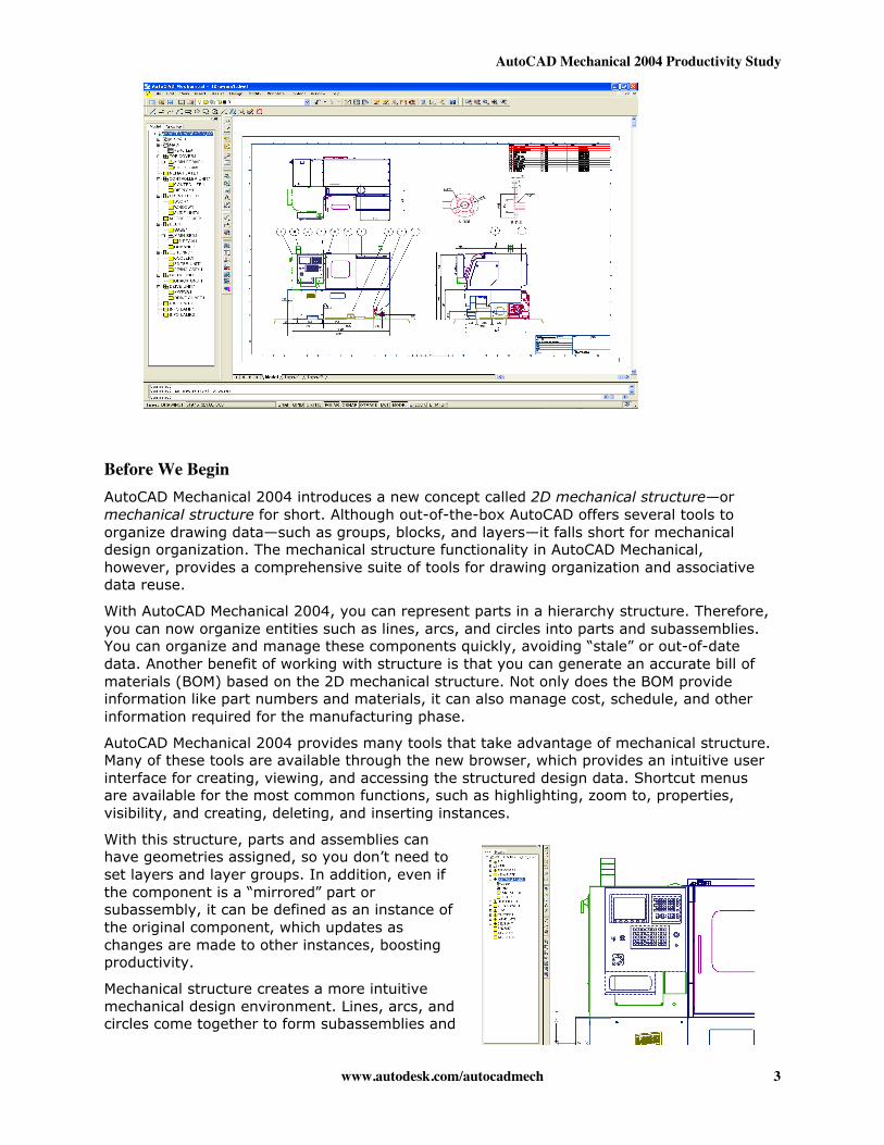
The following image shows the case study drawing. Ten common design tasks were used tocreate it from scratch, maintain it, and reuse it in other designs, using both AutoCAD andAutoCAD Mechanical software. The results clearly demonstrate that AutoCAD Mechanical isthe more productive 2D mechanical design system.
AutoCAD Mechanical 2004 Productivity Study
www.autodesk.com/autocadmech 3
Before We BeginAutoCAD Mechanical 2004 introduces a new concept called 2D mechanical structure—ormechanical structure for short. Although out-of-the-box AutoCAD offers several tools toorganize drawing data—such as groups, blocks, and layers—it falls short for mechanicaldesign organization. The mechanical structure functionality in AutoCAD Mechanical,however, provides a comprehensive suite of tools for drawing organization and associativedata reuse.
With AutoCAD Mechanical 2004, you can represent parts in a hierarchy structure. Therefore,you can now organize entities such as lines, arcs, and circles into parts and subassemblies.You can organize and manage these components quickly, avoiding “stale” or out-of-datedata. Another benefit of working with structure is that you can generate an accurate bill ofmaterials (BOM) based on the 2D mechanical structure. Not only does the BOM provideinformation like part numbers and materials, it can also manage cost, schedule, and otherinformation required for the manufacturing phase.
AutoCAD Mechanical 2004 provides many tools that take advantage of mechanical structure.Many of these tools are available through the new browser, which provides an intuitive userinterface for creating, viewing, and accessing the structured design data. Shortcut menusare available for the most common functions, such as highlighting, zoom to, properties,visibility, and creating, deleting, and inserting instances.
With this structure, parts and assemblies canhave geometries assigned, so you don’t need toset layers and layer groups. In addition, even ifthe component is a “mirrored” part orsubassembly, it can be defined as an instance ofthe original component, which updates aschanges are made to other instances, boostingproductivity.
Mechanical structure creates a more intuitivemechanical design environment. Lines, arcs, andcircles come together to form subassemblies and
AutoCAD Mechanical 2004 Productivity Study
www.autodesk.com/autocadmech 4
part views. Because the drawing structure is displayed in a browser, design intent is clearand more easily accessible.
In addition, the innovative 2D design tools in AutoCAD Mechanical
• Eliminate the creation of stale data• Enhance accurate BOM and parts lists• Reduce detailing time• Reduce editing• Reduce design errors associated with stale data
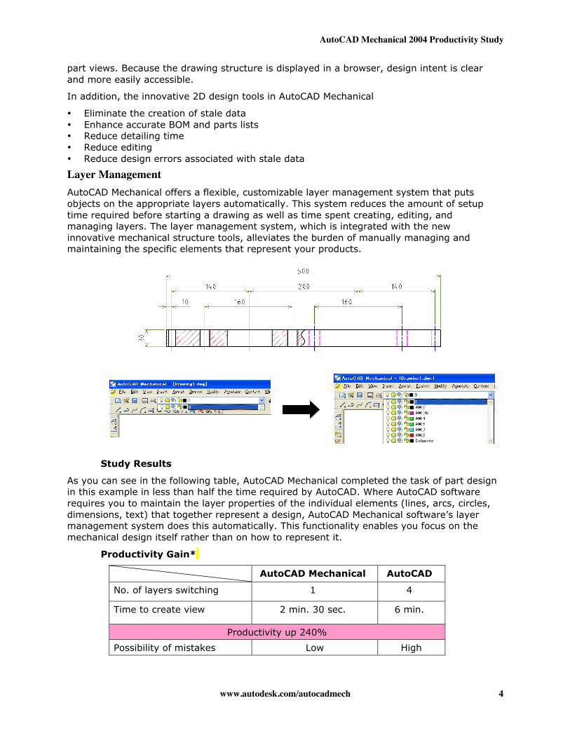
Layer ManagementAutoCAD Mechanical offers a flexible, customizable layer management system that putsobjects on the appropriate layers automatically. This system reduces the amount of setuptime required before starting a drawing as well as time spent creating, editing, andmanaging layers. The layer management system, which is integrated with the newinnovative mechanical structure tools, alleviates the burden of manually managing andmaintaining the specific elements that represent your products.
Study Results
As you can see in the following table, AutoCAD Mechanical completed the task of part designin this example in less than half the time required by AutoCAD. Where AutoCAD softwarerequires you to maintain the layer properties of the individual elements (lines, arcs, circles,dimensions, text) that together represent a design, AutoCAD Mechanical software’s layermanagement system does this automatically. This functionality enables you focus on themechanical design itself rather than on how to represent it.
Productivity Gain*
AutoCAD Mechanical AutoCAD
No. of layers switching 1 4
Time to create view 2 min. 30 sec. 6 min.
Productivity up 240%
Possibility of mistakes Low High
AutoCAD Mechanical 2004 Productivity Study
www.autodesk.com/autocadmech 5
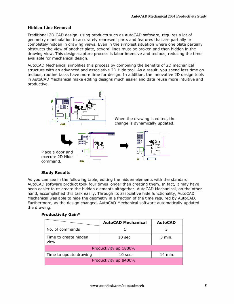
Hidden-Line RemovalTraditional 2D CAD design, using products such as AutoCAD software, requires a lot ofgeometry manipulation to accurately represent parts and features that are partially orcompletely hidden in drawing views. Even in the simplest situation where one plate partiallyobstructs the view of another plate, several lines must be broken and then hidden in thedrawing view. This design-capture process is labor intensive and tedious, reducing the timeavailable for mechanical design.
AutoCAD Mechanical simplifies this process by combining the benefits of 2D mechanicalstructure with an advanced and associative 2D Hide tool. As a result, you spend less time ontedious, routine tasks have more time for design. In addition, the innovative 2D design toolsin AutoCAD Mechanical make editing designs much easier and data reuse more intuitive andproductive.
Study Results
As you can see in the following table, editing the hidden elements with the standardAutoCAD software product took four times longer than creating them. In fact, it may havebeen easier to re-create the hidden elements altogether. AutoCAD Mechanical, on the otherhand, accomplished this task easily. Through its associative hide functionality, AutoCADMechanical was able to hide the geometry in a fraction of the time required by AutoCAD.Furthermore, as the design changed, AutoCAD Mechanical software automatically updatedthe drawing.
Productivity Gain*
AutoCAD Mechanical AutoCAD
No. of commands 1 3
Time to create hiddenview
10 sec. 3 min.
Productivity up 1800%
Time to update drawing 10 sec. 14 min.Productivity up 8400%
When the drawing is edited, thechange is dynamically updated.
Place a door andexecute 2D Hidecommand.
AutoCAD Mechanical 2004 Productivity Study
www.autodesk.com/autocadmech 6
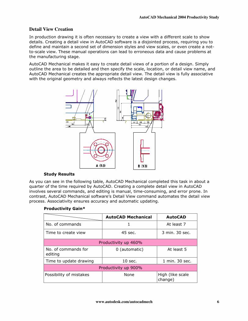
Detail View CreationIn production drawing it is often necessary to create a view with a different scale to showdetails. Creating a detail view in AutoCAD software is a disjointed process, requiring you todefine and maintain a second set of dimension styles and view scales, or even create a not-to-scale view. These manual operations can lead to erroneous data and cause problems atthe manufacturing stage.
AutoCAD Mechanical makes it easy to create detail views of a portion of a design. Simplyoutline the area to be detailed and then specify the scale, location, or detail view name, andAutoCAD Mechanical creates the appropriate detail view. The detail view is fully associativewith the original geometry and always reflects the latest design changes.
Study Results
As you can see in the following table, AutoCAD Mechanical completed this task in about aquarter of the time required by AutoCAD. Creating a complete detail view in AutoCADinvolves several commands, and editing is manual, time-consuming, and error prone. Incontrast, AutoCAD Mechanical software’s Detail View command automates the detail viewprocess. Associativity ensures accuracy and automatic updating.
Productivity Gain*
AutoCAD Mechanical AutoCAD
No. of commands 1 At least 7
Time to create view 45 sec. 3 min. 30 sec.
Productivity up 460%
No. of commands forediting
0 (automatic) At least 5
Time to update drawing 10 sec. 1 min. 30 sec.
Productivity up 900%
Possibility of mistakes None High (like scalechange)
AutoCAD Mechanical 2004 Productivity Study
www.autodesk.com/autocadmech 7
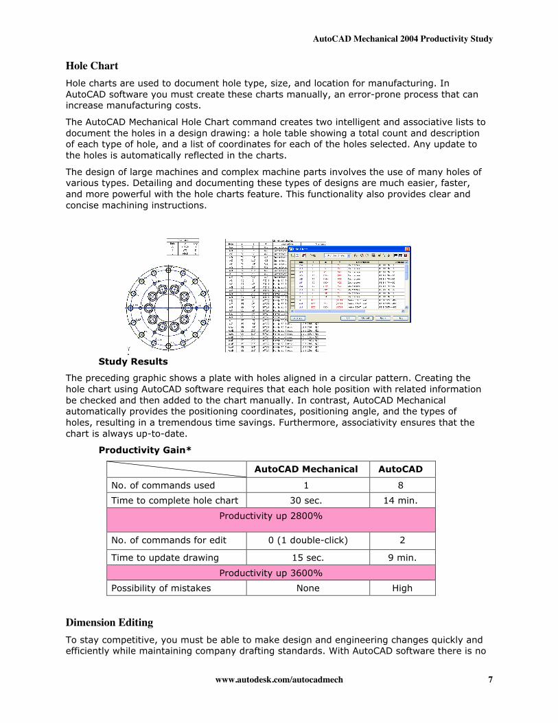
Hole ChartHole charts are used to document hole type, size, and location for manufacturing. InAutoCAD software you must create these charts manually, an error-prone process that canincrease manufacturing costs.
The AutoCAD Mechanical Hole Chart command creates two intelligent and associative lists todocument the holes in a design drawing: a hole table showing a total count and descriptionof each type of hole, and a list of coordinates for each of the holes selected. Any update tothe holes is automatically reflected in the charts.
The design of large machines and complex machine parts involves the use of many holes ofvarious types. Detailing and documenting these types of designs are much easier, faster,and more powerful with the hole charts feature. This functionality also provides clear andconcise machining instructions.
Study Results
The preceding graphic shows a plate with holes aligned in a circular pattern. Creating thehole chart using AutoCAD software requires that each hole position with related informationbe checked and then added to the chart manually. In contrast, AutoCAD Mechanicalautomatically provides the positioning coordinates, positioning angle, and the types ofholes, resulting in a tremendous time savings. Furthermore, associativity ensures that thechart is always up-to-date.
Productivity Gain*
AutoCAD Mechanical AutoCAD
No. of commands used 1 8
Time to complete hole chart 30 sec. 14 min.
Productivity up 2800%
No. of commands for edit 0 (1 double-click) 2
Time to update drawing 15 sec. 9 min.
Productivity up 3600%
Possibility of mistakes None High
Dimension EditingTo stay competitive, you must be able to make design and engineering changes quickly andefficiently while maintaining company drafting standards. With AutoCAD software there is no
AutoCAD Mechanical 2004 Productivity Study
www.autodesk.com/autocadmech 8
guarantee that design changes result in a standard, compliant drawing with properdimensional arrangement.
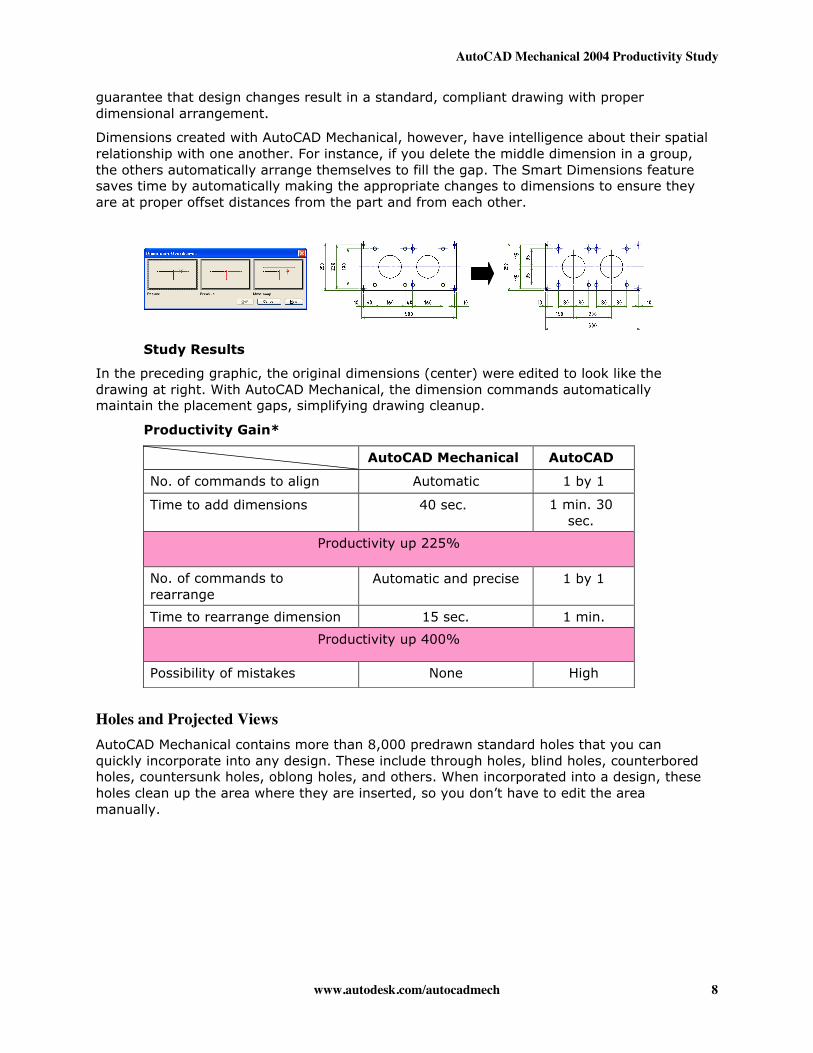
Dimensions created with AutoCAD Mechanical, however, have intelligence about their spatialrelationship with one another. For instance, if you delete the middle dimension in a group,the others automatically arrange themselves to fill the gap. The Smart Dimensions featuresaves time by automatically making the appropriate changes to dimensions to ensure theyare at proper offset distances from the part and from each other.
Study Results
In the preceding graphic, the original dimensions (center) were edited to look like thedrawing at right. With AutoCAD Mechanical, the dimension commands automaticallymaintain the placement gaps, simplifying drawing cleanup.
Productivity Gain*
Holes and Projected ViewsAutoCAD Mechanical contains more than 8,000 predrawn standard holes that you canquickly incorporate into any design. These include through holes, blind holes, counterboredholes, countersunk holes, oblong holes, and others. When incorporated into a design, theseholes clean up the area where they are inserted, so you don’t have to edit the areamanually.
AutoCAD Mechanical AutoCAD
No. of commands to align Automatic 1 by 1
Time to add dimensions 40 sec. 1 min. 30sec.
Productivity up 225%
No. of commands torearrange
Automatic and precise 1 by 1
Time to rearrange dimension 15 sec. 1 min.
Productivity up 400%
Possibility of mistakes None High
AutoCAD Mechanical 2004 Productivity Study
www.autodesk.com/autocadmech 9
Study Results
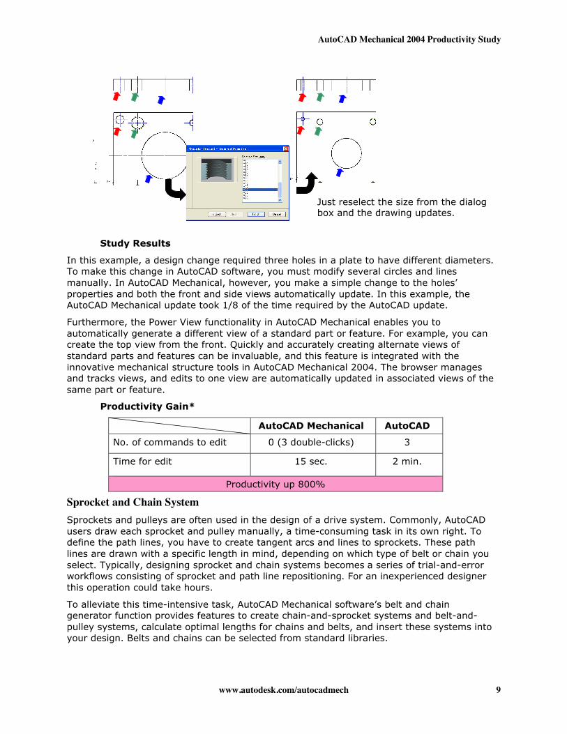
In this example, a design change required three holes in a plate to have different diameters.To make this change in AutoCAD software, you must modify several circles and linesmanually. In AutoCAD Mechanical, however, you make a simple change to the holes’properties and both the front and side views automatically update. In this example, theAutoCAD Mechanical update took 1/8 of the time required by the AutoCAD update.
Furthermore, the Power View functionality in AutoCAD Mechanical enables you toautomatically generate a different view of a standard part or feature. For example, you cancreate the top view from the front. Quickly and accurately creating alternate views ofstandard parts and features can be invaluable, and this feature is integrated with theinnovative mechanical structure tools in AutoCAD Mechanical 2004. The browser managesand tracks views, and edits to one view are automatically updated in associated views of thesame part or feature.
Productivity Gain*
AutoCAD Mechanical AutoCAD
No. of commands to edit 0 (3 double-clicks) 3
Time for edit 15 sec. 2 min.
Productivity up 800%
Sprocket and Chain SystemSprockets and pulleys are often used in the design of a drive system. Commonly, AutoCADusers draw each sprocket and pulley manually, a time-consuming task in its own right. Todefine the path lines, you have to create tangent arcs and lines to sprockets. These pathlines are drawn with a specific length in mind, depending on which type of belt or chain youselect. Typically, designing sprocket and chain systems becomes a series of trial-and-errorworkflows consisting of sprocket and path line repositioning. For an inexperienced designerthis operation could take hours.
To alleviate this time-intensive task, AutoCAD Mechanical software’s belt and chaingenerator function provides features to create chain-and-sprocket systems and belt-and-pulley systems, calculate optimal lengths for chains and belts, and insert these systems intoyour design. Belts and chains can be selected from standard libraries.
Just reselect the size from the dialogbox and the drawing updates.
AutoCAD Mechanical 2004 Productivity Study
www.autodesk.com/autocadmech 10
Study Results
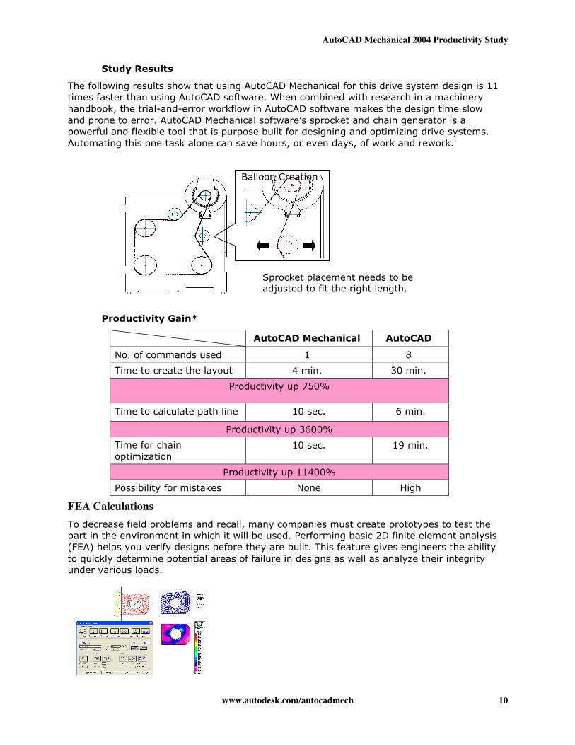
The following results show that using AutoCAD Mechanical for this drive system design is 11times faster than using AutoCAD software. When combined with research in a machineryhandbook, the trial-and-error workflow in AutoCAD software makes the design time slowand prone to error. AutoCAD Mechanical software’s sprocket and chain generator is apowerful and flexible tool that is purpose built for designing and optimizing drive systems.Automating this one task alone can save hours, or even days, of work and rework.
Productivity Gain*
AutoCAD Mechanical AutoCAD
No. of commands used 1 8
Time to create the layout 4 min. 30 min.
Productivity up 750%
Time to calculate path line 10 sec. 6 min.
Productivity up 3600%
Time for chainoptimization
10 sec. 19 min.
Productivity up 11400%
Possibility for mistakes None High
FEA CalculationsTo decrease field problems and recall, many companies must create prototypes to test thepart in the environment in which it will be used. Performing basic 2D finite element analysis(FEA) helps you verify designs before they are built. This feature gives engineers the abilityto quickly determine potential areas of failure in designs as well as analyze their integrityunder various loads.
Balloon Creation
Sprocket placement needs to beadjusted to fit the right length.
AutoCAD Mechanical 2004 Productivity Study
www.autodesk.com/autocadmech 11
Study Results
This example involves a hanging hook that required stress analysis. Since AutoCAD softwaredoes not provide 2D FEA functionality, designers must do calculations manually, referring toan engineering handbook. AutoCAD Mechanical, however, offers a simple 2D FEA feature.This powerful yet easy-to-use tool can determine the resistance capability of an objectunder a static load. This function enables you to add movable and fixed supports to the partto be analyzed as well as enter stress points, lines, and areas. As shown in the followingtable, AutoCAD Mechanical software’s analysis tools provided tremendous time savings overthe conventional mathematics required when using the basic AutoCAD program.
Productivity Gain*
AutoCAD Mechanical AutoCAD
No. of commands used 1 Nocommand
Time for calculation 30 sec. 27 min.
Productivity up 5400%
Possibility of mistakes Very Low Very High
Part BalloonsAs a design nears completion, designers commonly annotate an assembly drawing withballoons that identify components for a parts list. These balloons are traditionally createdmanually. Often, designers attempt to speed up the process through customization.
Study Results
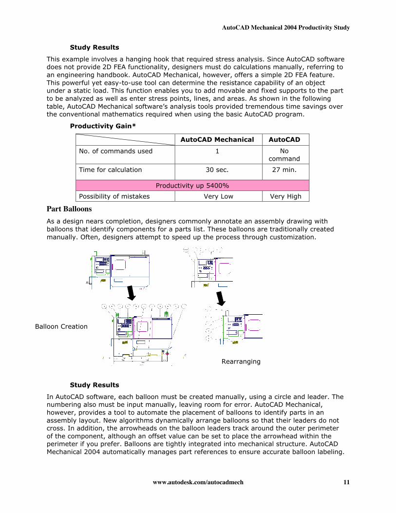
In AutoCAD software, each balloon must be created manually, using a circle and leader. Thenumbering also must be input manually, leaving room for error. AutoCAD Mechanical,however, provides a tool to automate the placement of balloons to identify parts in anassembly layout. New algorithms dynamically arrange balloons so that their leaders do notcross. In addition, the arrowheads on the balloon leaders track around the outer perimeterof the component, although an offset value can be set to place the arrowhead within theperimeter if you prefer. Balloons are tightly integrated into mechanical structure. AutoCADMechanical 2004 automatically manages part references to ensure accurate balloon labeling.
Balloon Creation
Rearranging
AutoCAD Mechanical 2004 Productivity Study
www.autodesk.com/autocadmech 12
Although only 11 balloons were created and rearranged in this study, imagine how the timesavings shown in the following table would increase as the assembly count increases.
Productivity Gain*
AutoCAD Mechanical AutoCAD
No. of commands 1 3 x eachballoon
Time to create balloons 20 sec. 5 min.
Productivity up 1500%
Time to rearrangeballoon
20 sec. 4 min.
Productivity up 1200%
Part Information and Parts ListAutoCAD Mechanical contains several commands for creating balloons and BOMs. Itsupports multiple parts lists per drawing, as well as features such as summation, positionlists, and report generators. The parts lists automatically recognize standard parts insertedfrom AutoCAD Mechanical. This functionality is tightly integrated with the new mechanicalstructure tools.
It is easy to create parts lists in drawings. In 2D design, BOM information is typicallymanaged by hand and input manually into an MRP (Manufacturing Resource Planning)system. In AutoCAD Mechanical, BOM information is associative to mechanical structure andis dynamically updated throughout the design process. BOM data can even be exported toan MRP or ERP (Enterprise Resource Planning) system.
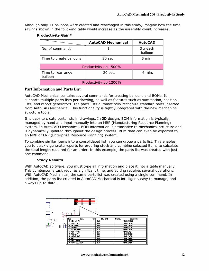
To combine similar items into a consolidated list, you can group a parts list. This enablesyou to quickly generate reports for ordering stock and combine selected items to calculatethe total length required for an order. In this example, the parts list was created with justone command.
Study Results
With AutoCAD software, you must type all information and place it into a table manually.This cumbersome task requires significant time, and editing requires several operations.With AutoCAD Mechanical, the same parts list was created using a single command. Inaddition, the parts list created in AutoCAD Mechanical is intelligent, easy to manage, andalways up-to-date.
AutoCAD Mechanical 2004 Productivity Study
www.autodesk.com/autocadmech 13
Productivity Gain*
AutoCAD Mechanical AutoCAD
No. of commands 1 3
Time to create parts list 10 sec. 13 min.
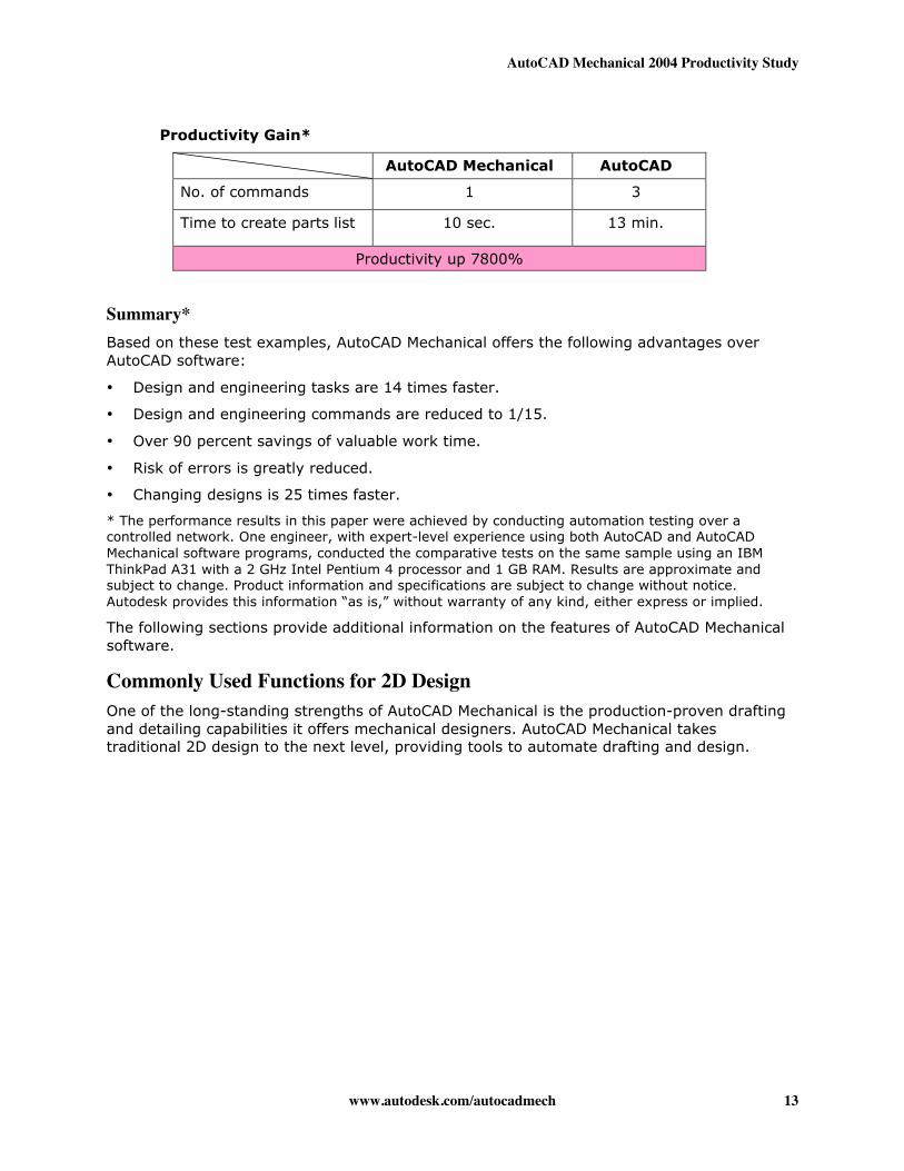
Productivity up 7800%
Summary*Based on these test examples, AutoCAD Mechanical offers the following advantages overAutoCAD software:
• Design and engineering tasks are 14 times faster.
• Design and engineering commands are reduced to 1/15.
• Over 90 percent savings of valuable work time.
• Risk of errors is greatly reduced.
• Changing designs is 25 times faster.
* The performance results in this paper were achieved by conducting automation testing over acontrolled network. One engineer, with expert-level experience using both AutoCAD and AutoCADMechanical software programs, conducted the comparative tests on the same sample using an IBMThinkPad A31 with a 2 GHz Intel Pentium 4 processor and 1 GB RAM. Results are approximate andsubject to change. Product information and specifications are subject to change without notice.Autodesk provides this information “as is,” without warranty of any kind, either express or implied.
The following sections provide additional information on the features of AutoCAD Mechanicalsoftware.
Commonly Used Functions for 2D DesignOne of the long-standing strengths of AutoCAD Mechanical is the production-proven draftingand detailing capabilities it offers mechanical designers. AutoCAD Mechanical takestraditional 2D design to the next level, providing tools to automate drafting and design.
AutoCAD Mechanical 2004 Productivity Study
www.autodesk.com/autocadmech 14
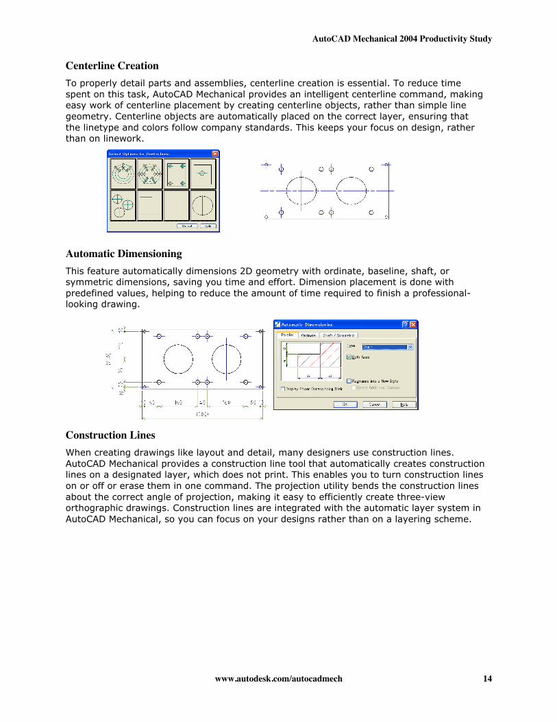
Centerline CreationTo properly detail parts and assemblies, centerline creation is essential. To reduce timespent on this task, AutoCAD Mechanical provides an intelligent centerline command, makingeasy work of centerline placement by creating centerline objects, rather than simple linegeometry. Centerline objects are automatically placed on the correct layer, ensuring thatthe linetype and colors follow company standards. This keeps your focus on design, ratherthan on linework.
Automatic DimensioningThis feature automatically dimensions 2D geometry with ordinate, baseline, shaft, orsymmetric dimensions, saving you time and effort. Dimension placement is done withpredefined values, helping to reduce the amount of time required to finish a professional-looking drawing.
Construction LinesWhen creating drawings like layout and detail, many designers use construction lines.AutoCAD Mechanical provides a construction line tool that automatically creates constructionlines on a designated layer, which does not print. This enables you to turn construction lineson or off or erase them in one command. The projection utility bends the construction linesabout the correct angle of projection, making it easy to efficiently create three-vieworthographic drawings. Construction lines are integrated with the automatic layer system inAutoCAD Mechanical, so you can focus on your designs rather than on a layering scheme.
AutoCAD Mechanical 2004 Productivity Study
www.autodesk.com/autocadmech 15
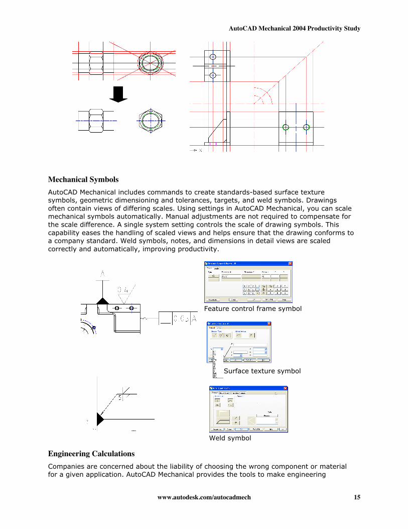
Mechanical SymbolsAutoCAD Mechanical includes commands to create standards-based surface texturesymbols, geometric dimensioning and tolerances, targets, and weld symbols. Drawingsoften contain views of differing scales. Using settings in AutoCAD Mechanical, you can scalemechanical symbols automatically. Manual adjustments are not required to compensate forthe scale difference. A single system setting controls the scale of drawing symbols. Thiscapability eases the handling of scaled views and helps ensure that the drawing conforms toa company standard. Weld symbols, notes, and dimensions in detail views are scaledcorrectly and automatically, improving productivity.
Engineering CalculationsCompanies are concerned about the liability of choosing the wrong component or materialfor a given application. AutoCAD Mechanical provides the tools to make engineering
Feature control frame symbol
Weld symbol
Surface texture symbol
AutoCAD Mechanical 2004 Productivity Study
www.autodesk.com/autocadmech 16
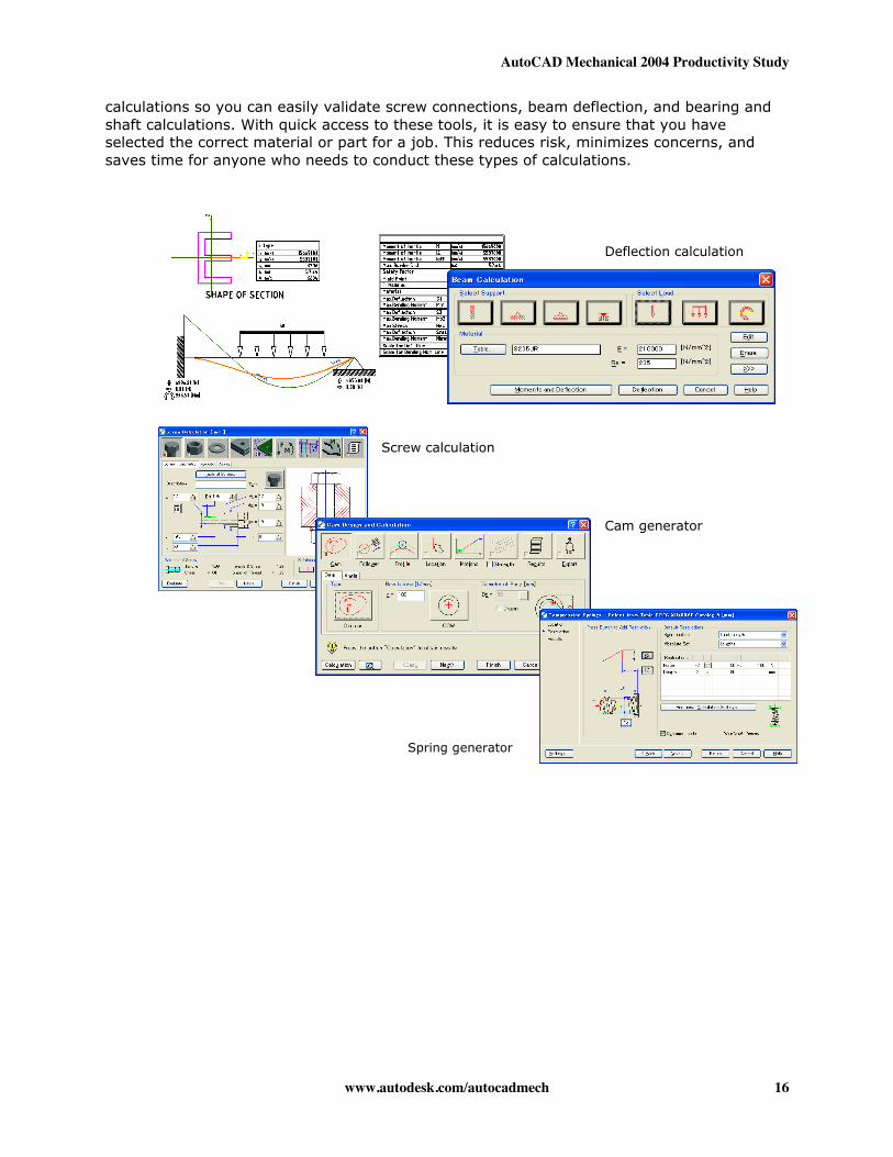
calculations so you can easily validate screw connections, beam deflection, and bearing andshaft calculations. With quick access to these tools, it is easy to ensure that you haveselected the correct material or part for a job. This reduces risk, minimizes concerns, andsaves time for anyone who needs to conduct these types of calculations.
Screw calculation
Cam generator
Deflection calculation
Spring generator
AutoCAD Mechanical 2004 Productivity Study
www.autodesk.com/autocadmech 17
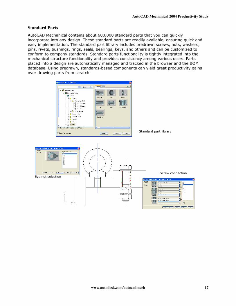
Standard PartsAutoCAD Mechanical contains about 600,000 standard parts that you can quicklyincorporate into any design. These standard parts are readily available, ensuring quick andeasy implementation. The standard part library includes predrawn screws, nuts, washers,pins, rivets, bushings, rings, seals, bearings, keys, and others and can be customized toconform to company standards. Standard parts functionality is tightly integrated into themechanical structure functionality and provides consistency among various users. Partsplaced into a design are automatically managed and tracked in the browser and the BOMdatabase. Using predrawn, standards-based components can yield great productivity gainsover drawing parts from scratch.
Standard part library
Eye nut selectionScrew connection
AutoCAD Mechanical 2004 Productivity Study
www.autodesk.com/autocadmech 18
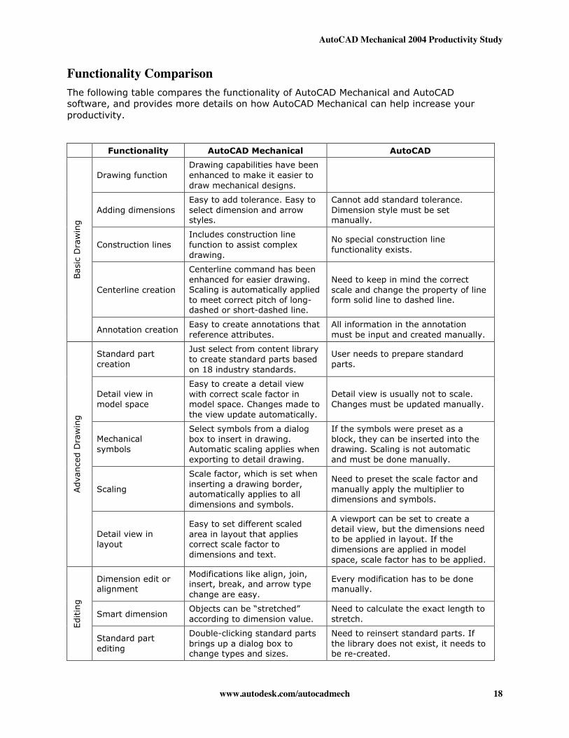
Functionality ComparisonThe following table compares the functionality of AutoCAD Mechanical and AutoCADsoftware, and provides more details on how AutoCAD Mechanical can help increase yourproductivity.
Functionality AutoCAD Mechanical AutoCAD
Drawing functionDrawing capabilities have beenenhanced to make it easier todraw mechanical designs.
Adding dimensionsEasy to add tolerance. Easy toselect dimension and arrowstyles.
Cannot add standard tolerance.Dimension style must be setmanually.
Construction linesIncludes construction linefunction to assist complexdrawing.
No special construction linefunctionality exists.
Centerline creation
Centerline command has beenenhanced for easier drawing.Scaling is automatically appliedto meet correct pitch of long-dashed or short-dashed line.
Need to keep in mind the correctscale and change the property of lineform solid line to dashed line.
Bas
ic D
raw
ing
Annotation creationEasy to create annotations thatreference attributes.
All information in the annotationmust be input and created manually.
Standard partcreation
Just select from content libraryto create standard parts basedon 18 industry standards.
User needs to prepare standardparts.
Detail view inmodel space
Easy to create a detail viewwith correct scale factor inmodel space. Changes made tothe view update automatically.
Detail view is usually not to scale.Changes must be updated manually.
Mechanicalsymbols
Select symbols from a dialogbox to insert in drawing.Automatic scaling applies whenexporting to detail drawing.
If the symbols were preset as ablock, they can be inserted into thedrawing. Scaling is not automaticand must be done manually.
Scaling
Scale factor, which is set wheninserting a drawing border,automatically applies to alldimensions and symbols.
Need to preset the scale factor andmanually apply the multiplier todimensions and symbols.
Adva
nce
d D
raw
ing
Detail view inlayout
Easy to set different scaledarea in layout that appliescorrect scale factor todimensions and text.
A viewport can be set to create adetail view, but the dimensions needto be applied in layout. If thedimensions are applied in modelspace, scale factor has to be applied.
Dimension edit oralignment
Modifications like align, join,insert, break, and arrow typechange are easy.
Every modification has to be donemanually.
Smart dimensionObjects can be “stretched”according to dimension value.
Need to calculate the exact length tostretch.
Editin
g
Standard partediting
Double-clicking standard partsbrings up a dialog box tochange types and sizes.
Need to reinsert standard parts. Ifthe library does not exist, it needs tobe re-created.
AutoCAD Mechanical 2004 Productivity Study
www.autodesk.com/autocadmech 19
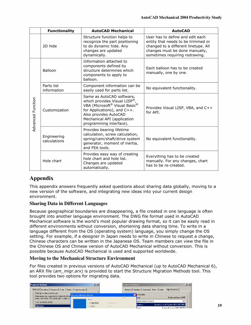
Functionality AutoCAD Mechanical AutoCAD
2D hide
Structure function helps torecognize the part positioningto do dynamic hide. Anychanges are updateddynamically.
User has to define and edit eachentity that needs to be trimmed orchanged to a different linetype. Allchanges must be done manually,sometimes requiring redrawing.
Balloon
Information attached tocomponents defined bystructure determines whichcomponents to apply toballoon.
Each balloon has to be createdmanually, one by one.
Parts listinformation
Component information can beeasily used for parts list. No equivalent functionality.
Customization
Same as AutoCAD software,which provides Visual LISP®,VBA (Microsoft® Visual Basic®
for Applications), and C++.Also provides AutoCADMechanical API (applicationprogramming interface).
Provides Visual LISP, VBA, and C++for API.
Engineeringcalculations
Provides bearing lifetimecalculation, screw calculation,spring/cam/shaft/drive systemgenerator, moment of inertia,and FEA tools.
No equivalent functionality.
Adva
nce
d F
unct
ion
Hole chart
Provides easy way of creatinghole chart and hole list.Changes are updatedautomatically.
Everything has to be createdmanually. For any changes, charthas to be re-created.
AppendixThis appendix answers frequently asked questions about sharing data globally, moving to anew version of the software, and integrating new ideas into your current designenvironment.
Sharing Data in Different LanguagesBecause geographical boundaries are disappearing, a file created in one language is oftenbrought into another language environment. The DWG file format used in AutoCADMechanical software is the world’s most popular drawing format, so it can be easily read indifferent environments without conversion, shortening data sharing time. To write in alanguage different from the OS (operating system) language, you simply change the OSsetting. For example, if a designer in Japan needs to write in Chinese to request a change,Chinese characters can be written in the Japanese OS. Team members can view the file inthe Chinese OS and Chinese version of AutoCAD Mechanical without conversion. This ispossible because AutoCAD Mechanical is used and supported worldwide.
Moving to the Mechanical Structure EnvironmentFor files created in previous versions of AutoCAD Mechanical (up to AutoCAD Mechanical 6),an ARX file (am_migr.arx) is provided to start the Structure Migration Methods tool. Thistool provides two options for migrating data.
AutoCAD Mechanical 2004 Productivity Study
www.autodesk.com/autocadmech 20
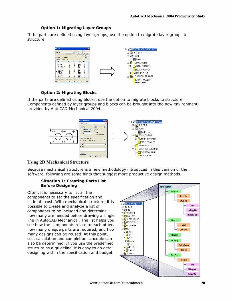
Option 1: Migrating Layer Groups
If the parts are defined using layer groups, use the option to migrate layer groups tostructure.
Option 2: Migrating Blocks
If the parts are defined using blocks, use the option to migrate blocks to structure.Components defined by layer groups and blocks can be brought into the new environmentprovided by AutoCAD Mechanical 2004.
Using 2D Mechanical StructureBecause mechanical structure is a new methodology introduced in this version of thesoftware, following are some hints that suggest more productive design methods.
Situation 1: Creating Parts ListBefore Designing
Often, it is necessary to list all thecomponents to set the specification andestimate cost. With mechanical structure, it ispossible to create and analyze a list ofcomponents to be included and determinehow many are needed before drawing a singleline in AutoCAD Mechanical. The list helps yousee how the components relate to each other,how many unique parts are required, and howmany designs can be reused. At this point,cost calculation and completion schedule canalso be determined. If you use the predefinedstructure as a guideline, it is easy to do detaildesigning within the specification and budget.
AutoCAD Mechanical 2004 Productivity Study
www.autodesk.com/autocadmech 21
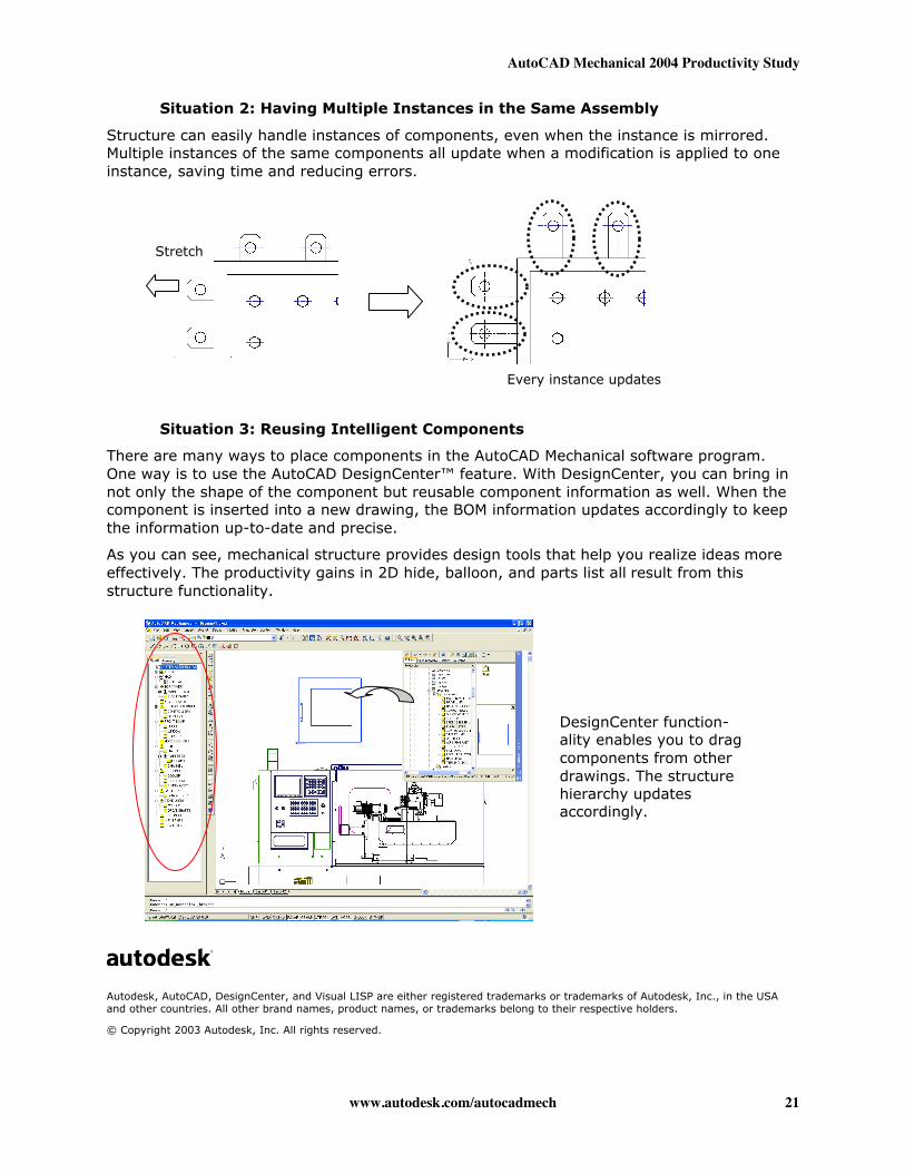
Situation 2: Having Multiple Instances in the Same Assembly
Structure can easily handle instances of components, even when the instance is mirrored.Multiple instances of the same components all update when a modification is applied to oneinstance, saving time and reducing errors.
Situation 3: Reusing Intelligent Components
There are many ways to place components in the AutoCAD Mechanical software program.One way is to use the AutoCAD DesignCenter™ feature. With DesignCenter, you can bring innot only the shape of the component but reusable component information as well. When thecomponent is inserted into a new drawing, the BOM information updates accordingly to keepthe information up-to-date and precise.
As you can see, mechanical structure provides design tools that help you realize ideas moreeffectively. The productivity gains in 2D hide, balloon, and parts list all result from thisstructure functionality.
Autodesk, AutoCAD, DesignCenter, and Visual LISP are either registered trademarks or trademarks of Autodesk, Inc., in the USAand other countries. All other brand names, product names, or trademarks belong to their respective holders.
© Copyright 2003 Autodesk, Inc. All rights reserved.
Stretch
Every instance updates
DesignCenter function-ality enables you to dragcomponents from otherdrawings. The structurehierarchy updatesaccordingly.