Embed Size (px)
Citation preview
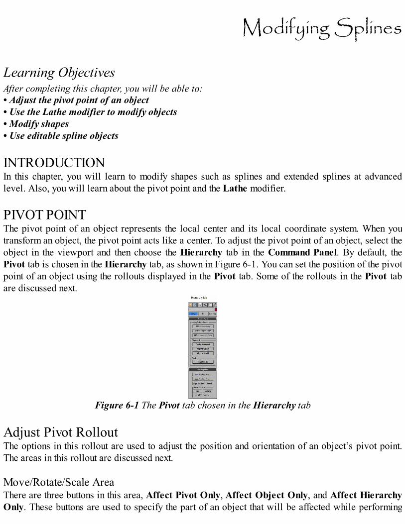
Modifying Splines Learning ObjectivesAfter completing this chapter, you will be able to:• Adjust the pivot point of an object• Use the Lathe modifier to modify objects• Modify shapes• Use editable spline objects INTRODUCTIONIn this chapter, you will learn to modify shapes such as splines and extended splines at advancedlevel. Also, you will learn about the pivot point and the Lathe modifier. PIVOT POINTThe pivot point of an object represents the local center and its local coordinate system. When youtransform an object, the pivot point acts like a center. To adjust the pivot point of an object, select theobject in the viewport and then choose the Hierarchy tab in the Command Panel. By default, thePivot tab is chosen in the Hierarchy tab, as shown in Figure 6-1. You can set the position of the pivotpoint of an object using the rollouts displayed in the Pivot tab. Some of the rollouts in the Pivot tabare discussed next.
Figure 6-1 The Pivot tab chosen in the Hierarchy tab Adjust Pivot RolloutThe options in this rollout are used to adjust the position and orientation of an object’s pivot point.The areas in this rollout are discussed next. Move/Rotate/Scale AreaThere are three buttons in this area, Affect Pivot Only, Affect Object Only, and Affect HierarchyOnly. These buttons are used to specify the part of an object that will be affected while performing
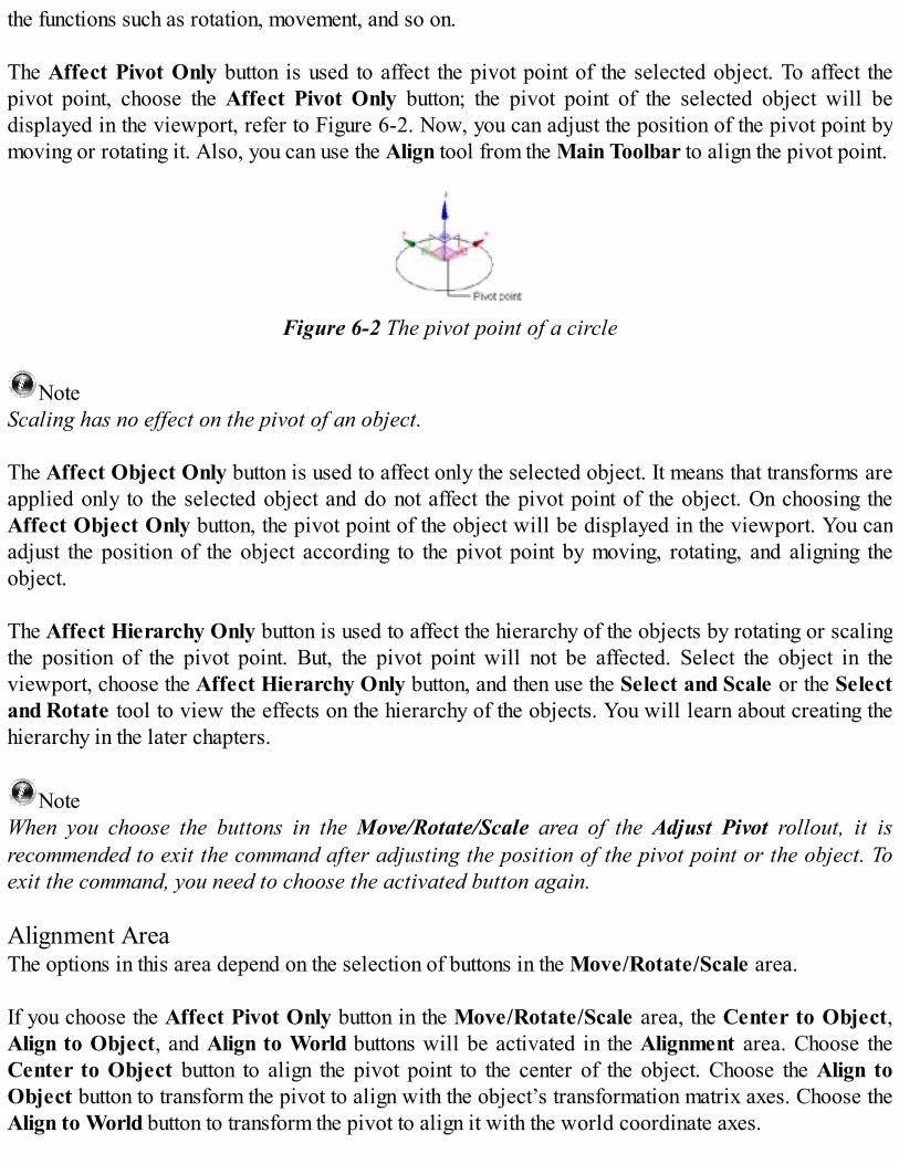
the functions such as rotation, movement, and so on. The Affect Pivot Only button is used to affect the pivot point of the selected object. To affect thepivot point, choose the Affect Pivot Only button; the pivot point of the selected object will bedisplayed in the viewport, refer to Figure 6-2. Now, you can adjust the position of the pivot point bymoving or rotating it. Also, you can use the Align tool from the Main Toolbar to align the pivot point.
Figure 6-2 The pivot point of a circle
NoteScaling has no effect on the pivot of an object. The Affect Object Only button is used to affect only the selected object. It means that transforms areapplied only to the selected object and do not affect the pivot point of the object. On choosing theAffect Object Only button, the pivot point of the object will be displayed in the viewport. You canadjust the position of the object according to the pivot point by moving, rotating, and aligning theobject. The Affect Hierarchy Only button is used to affect the hierarchy of the objects by rotating or scalingthe position of the pivot point. But, the pivot point will not be affected. Select the object in theviewport, choose the Affect Hierarchy Only button, and then use the Select and Scale or the Selectand Rotate tool to view the effects on the hierarchy of the objects. You will learn about creating thehierarchy in the later chapters.
NoteWhen you choose the buttons in the Move/Rotate/Scale area of the Adjust Pivot rollout, it isrecommended to exit the command after adjusting the position of the pivot point or the object. Toexit the command, you need to choose the activated button again. Alignment AreaThe options in this area depend on the selection of buttons in the Move/Rotate/Scale area. If you choose the Affect Pivot Only button in the Move/Rotate/Scale area, the Center to Object,Align to Object, and Align to World buttons will be activated in the Alignment area. Choose theCenter to Object button to align the pivot point to the center of the object. Choose the Align toObject button to transform the pivot to align with the object’s transformation matrix axes. Choose theAlign to World button to transform the pivot to align it with the world coordinate axes.

If you choose the Affect Object Only button in the Move/Rotate/Scale area, the Center to Pivot,Align to Pivot, and Align to World buttons will be activated in the Alignment area. Choose theCenter to Pivot button to align the center of the object to its pivot point. Choose the Align to Pivotbutton to transform the object to align its transformation matrix axes with the pivot point. Choose theAlign to World button to transform the object to align its transformation matrix axes with the worldcoordinate axes. If you choose the Affect Hierarchy Only button in the Move/Rotate/Scale area, then the options inthe Alignment area will be deactivated. Pivot AreaThe Reset Pivot button in this area is used to reset the position of the pivot point of the object. Working Pivot RolloutYou can use the working pivot to transform the objects without affecting their main pivot point at theobject or the sub-object level. For example, you can rotate an object in a scene about an arbitrarypoint without affecting its own pivot point.
NoteA scene has only one working pivot along with the gizmo, which is independent of other objects inthe scene, as shown in Figure 6-3.
Figure 6-3 The working pivot along with the gizmo in the scene You can modify the position of the working pivot. To do so, choose the Edit Working Pivot button;the working pivot will be displayed at the center of the scene, refer to Figure 6-3. Also, the EDIT WPtext will be displayed below each viewport label. You can modify the position of the working pivotby moving it.
If you choose the Use Working Pivot button and select any of the objects from the scene, then atransform gizmo will be displayed at the location of the working pivot, refer to Figures 6-4 and 6-5.Also, the USE WP text will be displayed below each viewport label. Now, the objects or the sub-objects in the scene will be transformed according to the working pivot.
Figure 6-4 The move transform gizmo displayed
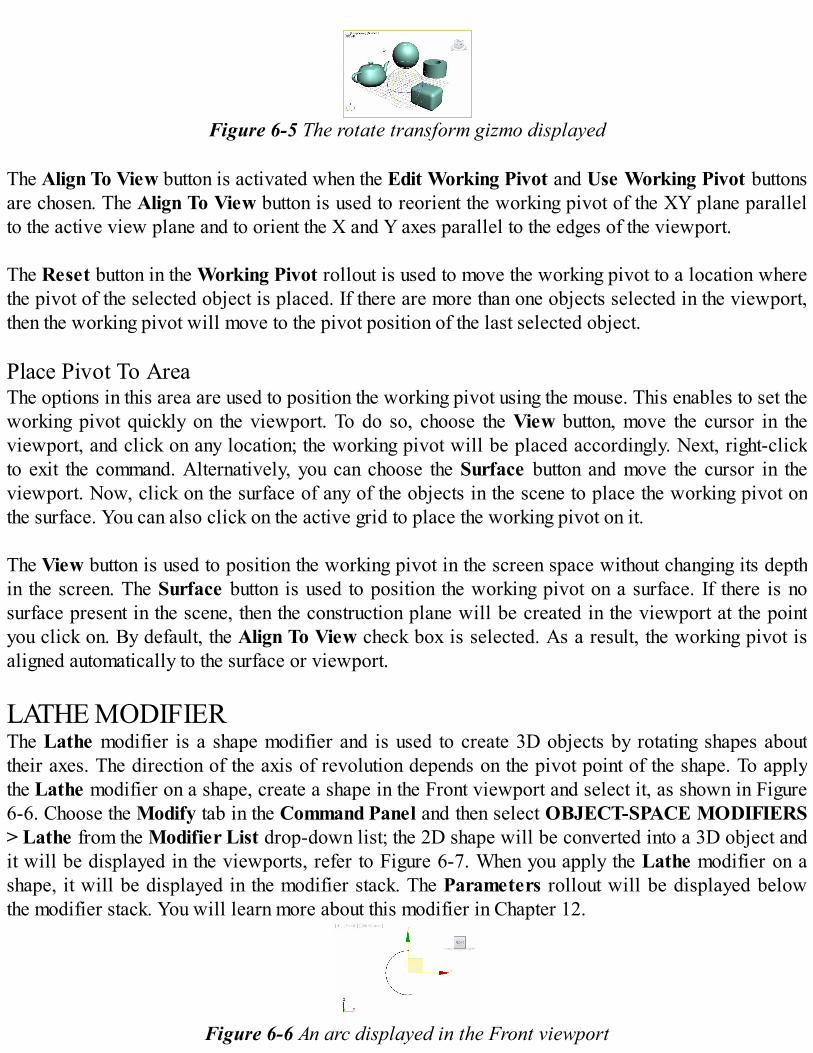
Figure 6-5 The rotate transform gizmo displayed
The Align To View button is activated when the Edit Working Pivot and Use Working Pivot buttonsare chosen. The Align To View button is used to reorient the working pivot of the XY plane parallelto the active view plane and to orient the X and Y axes parallel to the edges of the viewport. The Reset button in the Working Pivot rollout is used to move the working pivot to a location wherethe pivot of the selected object is placed. If there are more than one objects selected in the viewport,then the working pivot will move to the pivot position of the last selected object. Place Pivot To AreaThe options in this area are used to position the working pivot using the mouse. This enables to set theworking pivot quickly on the viewport. To do so, choose the View button, move the cursor in theviewport, and click on any location; the working pivot will be placed accordingly. Next, right-clickto exit the command. Alternatively, you can choose the Surface button and move the cursor in theviewport. Now, click on the surface of any of the objects in the scene to place the working pivot onthe surface. You can also click on the active grid to place the working pivot on it. The View button is used to position the working pivot in the screen space without changing its depthin the screen. The Surface button is used to position the working pivot on a surface. If there is nosurface present in the scene, then the construction plane will be created in the viewport at the pointyou click on. By default, the Align To View check box is selected. As a result, the working pivot isaligned automatically to the surface or viewport. LATHE MODIFIERThe Lathe modifier is a shape modifier and is used to create 3D objects by rotating shapes abouttheir axes. The direction of the axis of revolution depends on the pivot point of the shape. To applythe Lathe modifier on a shape, create a shape in the Front viewport and select it, as shown in Figure6-6. Choose the Modify tab in the Command Panel and then select OBJECT-SPACE MODIFIERS> Lathe from the Modifier List drop-down list; the 2D shape will be converted into a 3D object andit will be displayed in the viewports, refer to Figure 6-7. When you apply the Lathe modifier on ashape, it will be displayed in the modifier stack. The Parameters rollout will be displayed belowthe modifier stack. You will learn more about this modifier in Chapter 12.
Figure 6-6 An arc displayed in the Front viewport
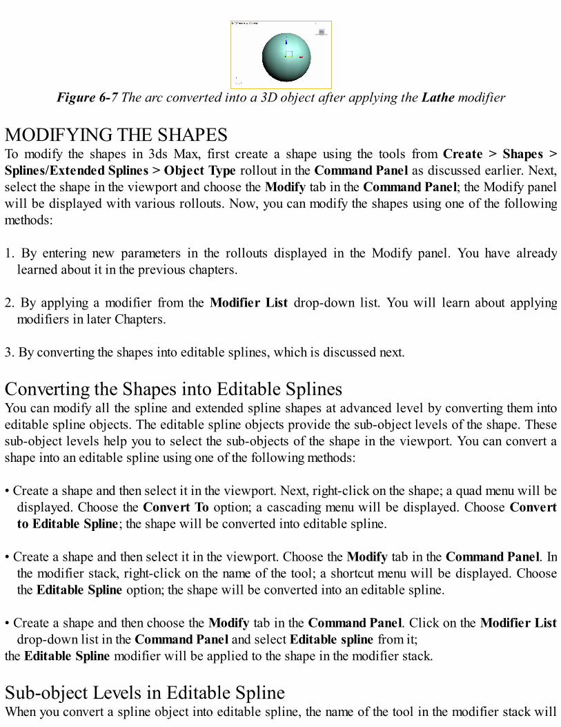
Figure 6-7 The arc converted into a 3D object after applying the Lathe modifier MODIFYING THE SHAPESTo modify the shapes in 3ds Max, first create a shape using the tools from Create > Shapes >Splines/Extended Splines > Object Type rollout in the Command Panel as discussed earlier. Next,select the shape in the viewport and choose the Modify tab in the Command Panel; the Modify panelwill be displayed with various rollouts. Now, you can modify the shapes using one of the followingmethods: 1. By entering new parameters in the rollouts displayed in the Modify panel. You have already
learned about it in the previous chapters. 2. By applying a modifier from the Modifier List drop-down list. You will learn about applying
modifiers in later Chapters. 3. By converting the shapes into editable splines, which is discussed next. Converting the Shapes into Editable SplinesYou can modify all the spline and extended spline shapes at advanced level by converting them intoeditable spline objects. The editable spline objects provide the sub-object levels of the shape. Thesesub-object levels help you to select the sub-objects of the shape in the viewport. You can convert ashape into an editable spline using one of the following methods: • Create a shape and then select it in the viewport. Next, right-click on the shape; a quad menu will be
displayed. Choose the Convert To option; a cascading menu will be displayed. Choose Convertto Editable Spline; the shape will be converted into editable spline.
• Create a shape and then select it in the viewport. Choose the Modify tab in the Command Panel. Inthe modifier stack, right-click on the name of the tool; a shortcut menu will be displayed. Choosethe Editable Spline option; the shape will be converted into an editable spline.
• Create a shape and then choose the Modify tab in the Command Panel. Click on the Modifier List
drop-down list in the Command Panel and select Editable spline from it;the Editable Spline modifier will be applied to the shape in the modifier stack. Sub-object Levels in Editable SplineWhen you convert a spline object into editable spline, the name of the tool in the modifier stack will

be replaced by Editable Spline. This level is known as the object level. Click on the plus sign on theleft of the Editable Spline to view the sub-object levels such asVertex, Segment, and Spline, asshown in Figure 6-8. On converting a spline object into editable spline, various rollouts suchas Rendering, Interpolation, Selection, Soft Selection, and Geometry will also be displayed in theModify panel, refer to Figure 6-8. These sub-object levels and rollouts are discussed next.
Figure 6-8 The sub-object levels and rollouts displayed
Sub-object LevelsThe sub-object levels help you to modify the object by moving, rotating, and scaling the sub-objects.To do so, select one of the sub-object levels in the modifier stack; it will be activated and turnyellow. Also, it will prompt you to select the corresponding sub-objects in the viewport. You canselect a sub-object in the viewport by clicking on it. If you want to add more sub-objects, then holdthe CTRL key and click on the sub-objects that you want to add. You can also drag a selection boxaround the sub-objects to select them simultaneously. These sub-objects are discussed next.
Vertex
The vertex is a point on the spline. To modify an object using vertices, select the Vertex sub-object level; the white and yellow colored vertices of the spline will be displayed in the viewports,as shown in Figure 6-9. The yellow colored vertex is the first vertex or the starting point of thespline, refer to Figure 6-9. There are various types of vertices such as bezier, corner, smooth, and bezier corner vertices, whichdepend on the type of spline. You can convert a vertex into a bezier, corner, smooth, or bezier cornervertex. To do so, select a vertex in the viewport and right-click on it; a quad menu will be displayed,as shown in Figure 6-10. Choose the type of vertex from the quad menu, refer to Figure 6-10; thevertex will change based on the option chosen from the quad menu.
Figure 6-9 The vertices of an arc spline displayed after selecting the Vertex sub-object level
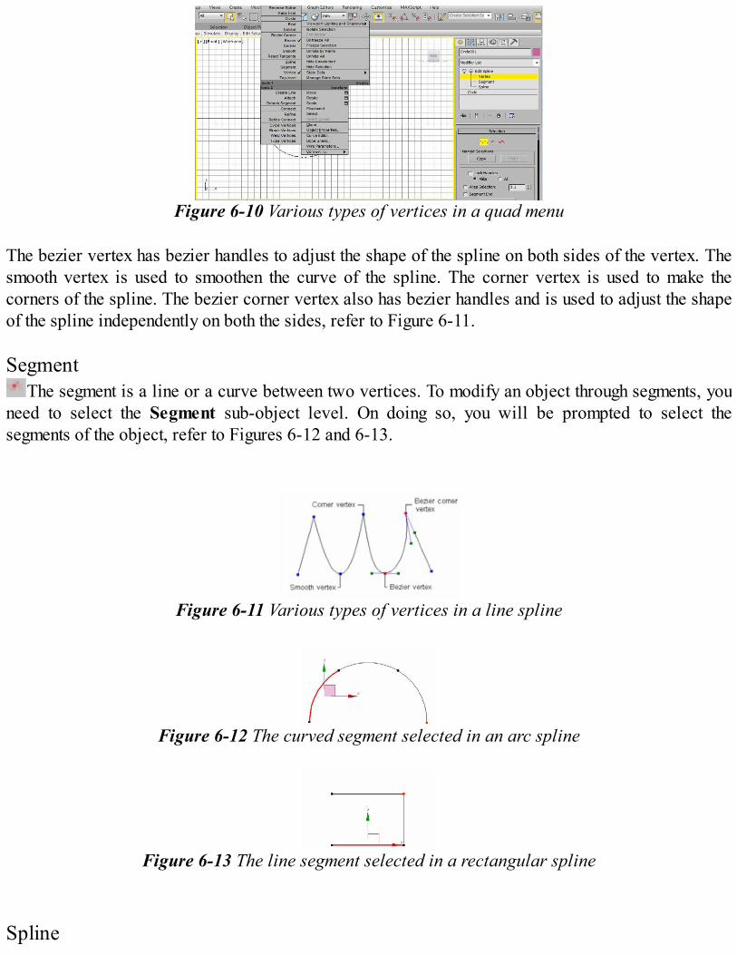
Figure 6-10 Various types of vertices in a quad menu
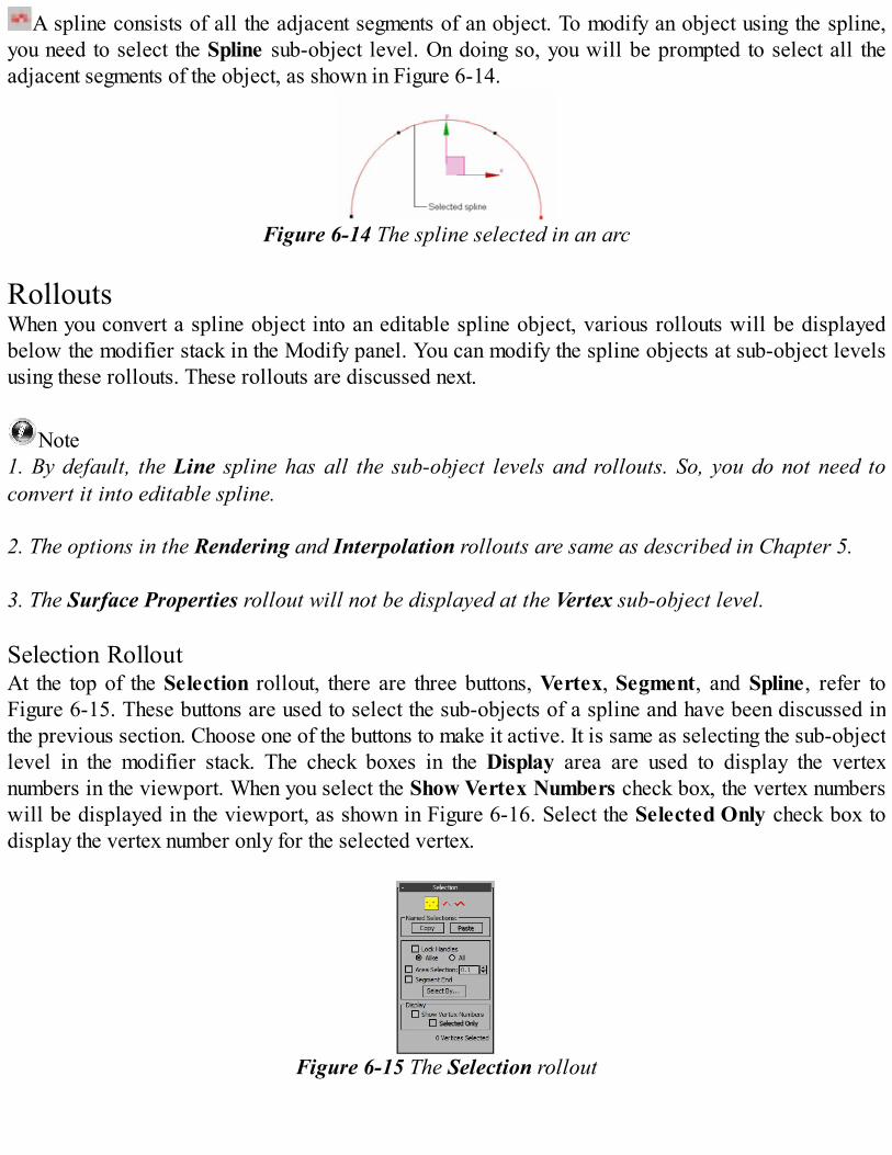
The bezier vertex has bezier handles to adjust the shape of the spline on both sides of the vertex. Thesmooth vertex is used to smoothen the curve of the spline. The corner vertex is used to make thecorners of the spline. The bezier corner vertex also has bezier handles and is used to adjust the shapeof the spline independently on both the sides, refer to Figure 6-11.
Segment
The segment is a line or a curve between two vertices. To modify an object through segments, youneed to select the Segment sub-object level. On doing so, you will be prompted to select thesegments of the object, refer to Figures 6-12 and 6-13.
Figure 6-11 Various types of vertices in a line spline
Figure 6-12 The curved segment selected in an arc spline
Figure 6-13 The line segment selected in a rectangular spline
Spline
A spline consists of all the adjacent segments of an object. To modify an object using the spline,you need to select the Spline sub-object level. On doing so, you will be prompted to select all theadjacent segments of the object, as shown in Figure 6-14.
Figure 6-14 The spline selected in an arc RolloutsWhen you convert a spline object into an editable spline object, various rollouts will be displayedbelow the modifier stack in the Modify panel. You can modify the spline objects at sub-object levelsusing these rollouts. These rollouts are discussed next.
Note1. By default, the Line spline has all the sub-object levels and rollouts. So, you do not need toconvert it into editable spline.
2. The options in the Rendering and Interpolation rollouts are same as described in Chapter 5. 3. The Surface Properties rollout will not be displayed at the Vertex sub-object level. Selection RolloutAt the top of the Selection rollout, there are three buttons, Vertex, Segment, and Spline, refer toFigure 6-15. These buttons are used to select the sub-objects of a spline and have been discussed inthe previous section. Choose one of the buttons to make it active. It is same as selecting the sub-objectlevel in the modifier stack. The check boxes in the Display area are used to display the vertexnumbers in the viewport. When you select the Show Vertex Numbers check box, the vertex numberswill be displayed in the viewport, as shown in Figure 6-16. Select the Selected Only check box todisplay the vertex number only for the selected vertex.
Figure 6-15 The Selection rollout
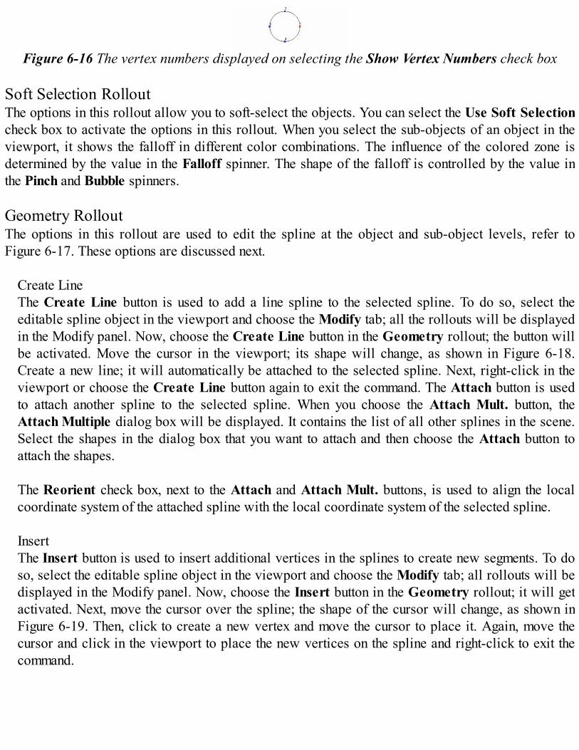
Figure 6-16 The vertex numbers displayed on selecting the Show Vertex Numbers check box
Soft Selection RolloutThe options in this rollout allow you to soft-select the objects. You can select the Use Soft Selectioncheck box to activate the options in this rollout. When you select the sub-objects of an object in theviewport, it shows the falloff in different color combinations. The influence of the colored zone isdetermined by the value in the Falloff spinner. The shape of the falloff is controlled by the value inthe Pinch and Bubble spinners.
Geometry RolloutThe options in this rollout are used to edit the spline at the object and sub-object levels, refer toFigure 6-17. These options are discussed next.
Create LineThe Create Line button is used to add a line spline to the selected spline. To do so, select theeditable spline object in the viewport and choose the Modify tab; all the rollouts will be displayedin the Modify panel. Now, choose the Create Line button in the Geometry rollout; the button willbe activated. Move the cursor in the viewport; its shape will change, as shown in Figure 6-18.Create a new line; it will automatically be attached to the selected spline. Next, right-click in theviewport or choose the Create Line button again to exit the command. The Attach button is usedto attach another spline to the selected spline. When you choose the Attach Mult. button, theAttach Multiple dialog box will be displayed. It contains the list of all other splines in the scene.Select the shapes in the dialog box that you want to attach and then choose the Attach button toattach the shapes. The Reorient check box, next to the Attach and Attach Mult. buttons, is used to align the localcoordinate system of the attached spline with the local coordinate system of the selected spline. InsertThe Insert button is used to insert additional vertices in the splines to create new segments. To doso, select the editable spline object in the viewport and choose the Modify tab; all rollouts will bedisplayed in the Modify panel. Now, choose the Insert button in the Geometry rollout; it will getactivated. Next, move the cursor over the spline; the shape of the cursor will change, as shown inFigure 6-19. Then, click to create a new vertex and move the cursor to place it. Again, move thecursor and click in the viewport to place the new vertices on the spline and right-click to exit thecommand.
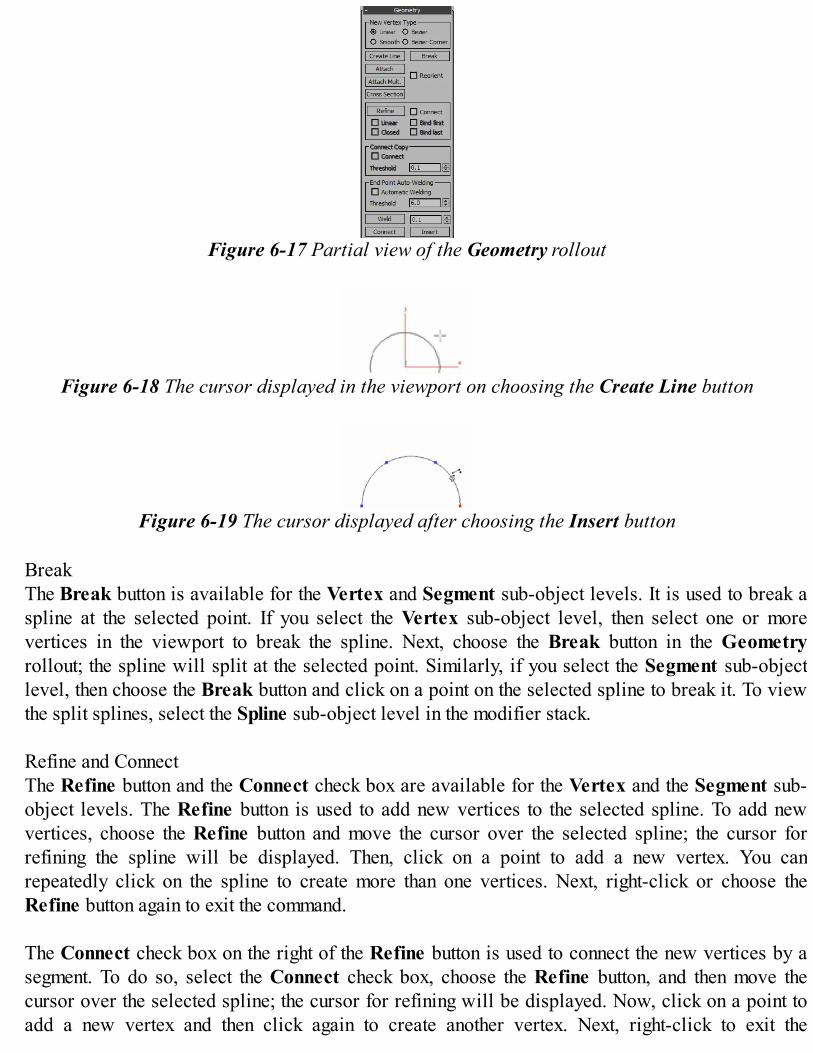
Figure 6-17 Partial view of the Geometry rollout
Figure 6-18 The cursor displayed in the viewport on choosing the Create Line button
Figure 6-19 The cursor displayed after choosing the Insert button
BreakThe Break button is available for the Vertex and Segment sub-object levels. It is used to break aspline at the selected point. If you select the Vertex sub-object level, then select one or morevertices in the viewport to break the spline. Next, choose the Break button in the Geometryrollout; the spline will split at the selected point. Similarly, if you select the Segment sub-objectlevel, then choose the Break button and click on a point on the selected spline to break it. To viewthe split splines, select the Spline sub-object level in the modifier stack. Refine and ConnectThe Refine button and the Connect check box are available for the Vertex and the Segment sub-object levels. The Refine button is used to add new vertices to the selected spline. To add newvertices, choose the Refine button and move the cursor over the selected spline; the cursor forrefining the spline will be displayed. Then, click on a point to add a new vertex. You canrepeatedly click on the spline to create more than one vertices. Next, right-click or choose theRefine button again to exit the command. The Connect check box on the right of the Refine button is used to connect the new vertices by asegment. To do so, select the Connect check box, choose the Refine button, and then move thecursor over the selected spline; the cursor for refining will be displayed. Now, click on a point toadd a new vertex and then click again to create another vertex. Next, right-click to exit the
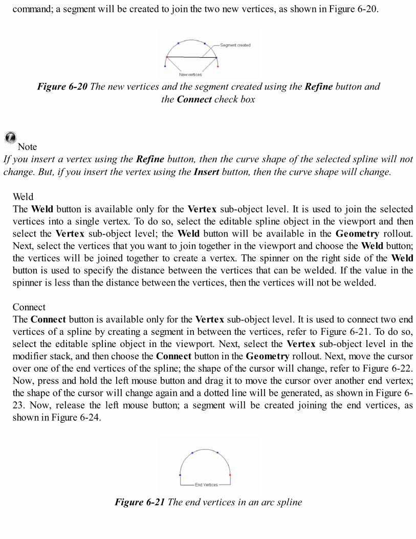
command; a segment will be created to join the two new vertices, as shown in Figure 6-20.
Figure 6-20 The new vertices and the segment created using the Refine button andthe Connect check box
NoteIf you insert a vertex using the Refine button, then the curve shape of the selected spline will notchange. But, if you insert the vertex using the Insert button, then the curve shape will change.
WeldThe Weld button is available only for the Vertex sub-object level. It is used to join the selectedvertices into a single vertex. To do so, select the editable spline object in the viewport and thenselect the Vertex sub-object level; the Weld button will be available in the Geometry rollout.Next, select the vertices that you want to join together in the viewport and choose the Weld button;the vertices will be joined together to create a vertex. The spinner on the right side of the Weldbutton is used to specify the distance between the vertices that can be welded. If the value in thespinner is less than the distance between the vertices, then the vertices will not be welded.
ConnectThe Connect button is available only for the Vertex sub-object level. It is used to connect two endvertices of a spline by creating a segment in between the vertices, refer to Figure 6-21. To do so,select the editable spline object in the viewport. Next, select the Vertex sub-object level in themodifier stack, and then choose the Connect button in the Geometry rollout. Next, move the cursorover one of the end vertices of the spline; the shape of the cursor will change, refer to Figure 6-22.Now, press and hold the left mouse button and drag it to move the cursor over another end vertex;the shape of the cursor will change again and a dotted line will be generated, as shown in Figure 6-23. Now, release the left mouse button; a segment will be created joining the end vertices, asshown in Figure 6-24.
Figure 6-21 The end vertices in an arc spline

Figure 6-23 The cursor over another end vertex and the dotted line displayed
Figure 6-22 The cursor over one of the end vertices
Figure 6-24 The end vertices connected with a segment
Make FirstThe Make First button is used to make any vertex of the spline as its first vertex or the startingpoint. To do so, select a vertex of the spline in the viewport and choose the Make First button inthe Geometry rollout; the selected vertex will turn yellow and become the first vertex of thespline.
NoteIn an open spline such as line, arc, and so on, only the end vertex can be the first vertex.
FuseThe Fuse button is used to move all the selected vertices of a spline to their average center. Selectthe vertices of a spline in the viewport, as shown in Figure 6-25, and then choose the Fuse button inthe Geometry rollout; the selected vertices will fuse together at their average center, as shown inFigure 6-26.
Figure 6-25 The selected vertices inside the rectangular area
Figure 6-26 The selected vertices fused at their average center
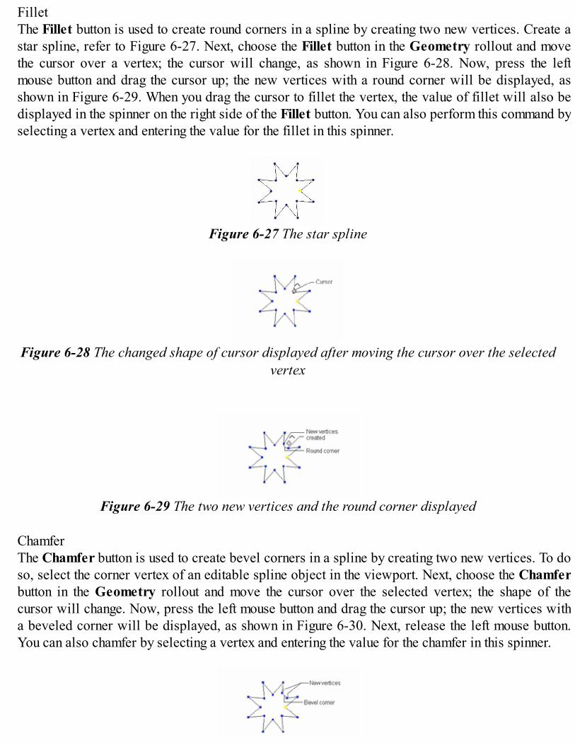
FilletThe Fillet button is used to create round corners in a spline by creating two new vertices. Create astar spline, refer to Figure 6-27. Next, choose the Fillet button in the Geometry rollout and movethe cursor over a vertex; the cursor will change, as shown in Figure 6-28. Now, press the leftmouse button and drag the cursor up; the new vertices with a round corner will be displayed, asshown in Figure 6-29. When you drag the cursor to fillet the vertex, the value of fillet will also bedisplayed in the spinner on the right side of the Fillet button. You can also perform this command byselecting a vertex and entering the value for the fillet in this spinner.
Figure 6-27 The star spline
Figure 6-28 The changed shape of cursor displayed after moving the cursor over the selectedvertex
Figure 6-29 The two new vertices and the round corner displayed
ChamferThe Chamfer button is used to create bevel corners in a spline by creating two new vertices. To doso, select the corner vertex of an editable spline object in the viewport. Next, choose the Chamferbutton in the Geometry rollout and move the cursor over the selected vertex; the shape of thecursor will change. Now, press the left mouse button and drag the cursor up; the new vertices witha beveled corner will be displayed, as shown in Figure 6-30. Next, release the left mouse button.You can also chamfer by selecting a vertex and entering the value for the chamfer in this spinner.

Figure 6-30 The new vertices with a beveled corner
Hide and Unhide AllThe Hide and Unhide All buttons are available for all sub-object levels in the editable splineobject. The Hide button is used to hide the selected sub-object in the viewport. The Unhide Allbutton is used to show all hidden sub-objects in the viewport. To hide the sub-objects of theeditable spline object, select them in the viewport and choose the Hide button in the Geometryrollout. Similarly, to unhide the hidden sub-objects, choose the Unhide All button in the Geometryrollout.
DeleteThe Delete button is available at all the sub-object levels and is used to delete the selected sub-objects in the viewport. To do so, select a sub-object in the viewport and choose the Delete button;the selected sub-object will be deleted. DivideThe Divide button is available only for the Segment sub-object level. It is used to subdivide theselected segment by inserting a number of vertices on it. The number of vertices to be inserted canbe set in the spinner on the right side of the Divide button. To subdivide a selected segment, selectthe Segment sub-object in the viewport, as shown in Figure 6-31. Next, choose the Divide button;the selected segment will be sub-divided, refer to Figure 6-32.
DetachThe Detach button is available at the Segment and Spline sub-object levels. It is used to detachthe selected sub-objects from the original one and create a new shape. To do so, select one or moresegments of the editable spline object in the viewport, refer to Figure 6-33. Next, choose theDetach button in the Geometry rollout; the Detach dialog box will be displayed, as shown inFigure 6-34. By default, the name of the new shape will be displayed as Shape001 in the Detachas text box. Modify the name if you want and then choose the OK button; the detached segment willnow behave like a new independent shape, refer to Figure 6-35.
Figure 6-31 A segment selected in the circle spline
Figure 6-32 The selected segment sub-divided after using the Divide button
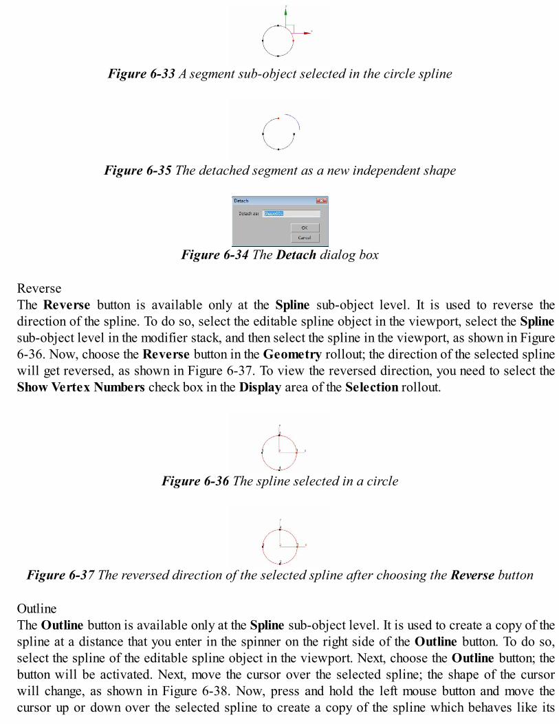
Figure 6-33 A segment sub-object selected in the circle spline
Figure 6-35 The detached segment as a new independent shape
Figure 6-34 The Detach dialog box
ReverseThe Reverse button is available only at the Spline sub-object level. It is used to reverse thedirection of the spline. To do so, select the editable spline object in the viewport, select the Splinesub-object level in the modifier stack, and then select the spline in the viewport, as shown in Figure6-36. Now, choose the Reverse button in the Geometry rollout; the direction of the selected splinewill get reversed, as shown in Figure 6-37. To view the reversed direction, you need to select theShow Vertex Numbers check box in the Display area of the Selection rollout.
Figure 6-36 The spline selected in a circle
Figure 6-37 The reversed direction of the selected spline after choosing the Reverse button
OutlineThe Outline button is available only at the Spline sub-object level. It is used to create a copy of thespline at a distance that you enter in the spinner on the right side of the Outline button. To do so,select the spline of the editable spline object in the viewport. Next, choose the Outline button; thebutton will be activated. Next, move the cursor over the selected spline; the shape of the cursorwill change, as shown in Figure 6-38. Now, press and hold the left mouse button and move thecursor up or down over the selected spline to create a copy of the spline which behaves like its
outline, as shown in Figure 6-39. Now, release the left mouse button. Also, right-click in theviewport or choose the Outline button again to exit the command.
Figure 6-38 The shape of the cursor changed after choosing the Outline button
Figure 6-39 A copy of the spline created as an outline of the selected spline
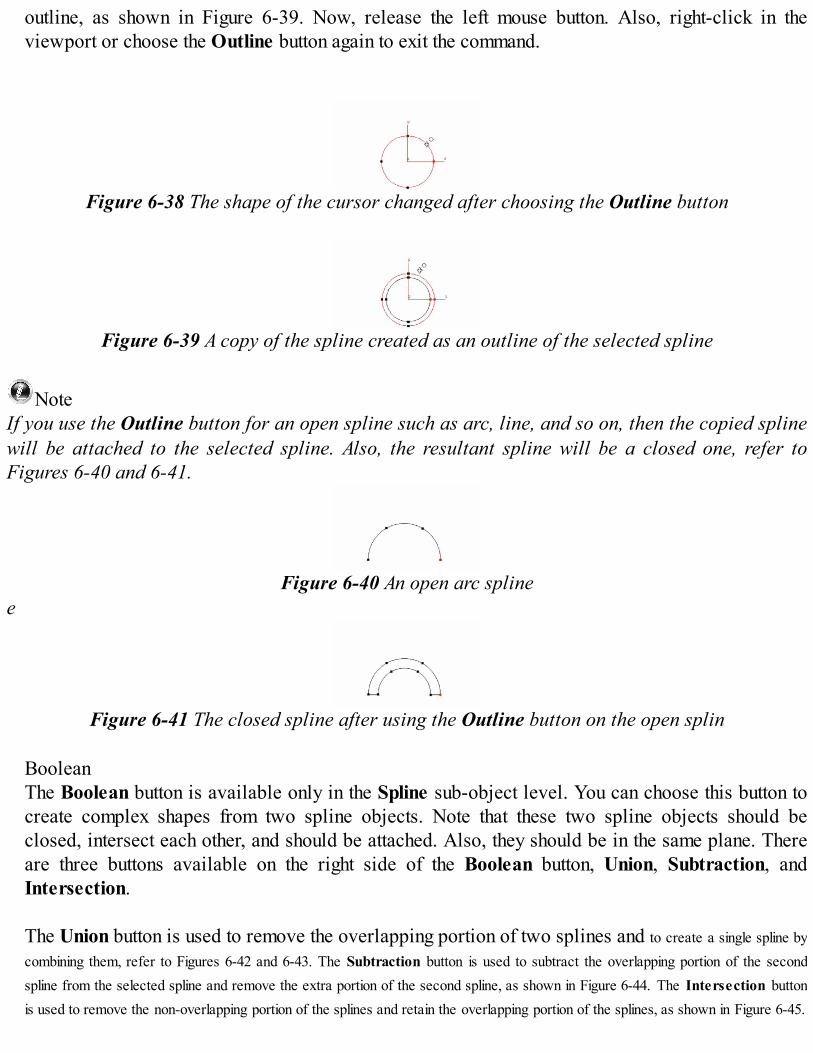
NoteIf you use the Outline button for an open spline such as arc, line, and so on, then the copied splinewill be attached to the selected spline. Also, the resultant spline will be a closed one, refer toFigures 6-40 and 6-41.
Figure 6-40 An open arc splinee
Figure 6-41 The closed spline after using the Outline button on the open splin
BooleanThe Boolean button is available only in the Spline sub-object level. You can choose this button tocreate complex shapes from two spline objects. Note that these two spline objects should beclosed, intersect each other, and should be attached. Also, they should be in the same plane. Thereare three buttons available on the right side of the Boolean button, Union, Subtraction, andIntersection. The Union button is used to remove the overlapping portion of two splines and to create a single spline bycombining them, refer to Figures 6-42 and 6-43. The Subtraction button is used to subtract the overlapping portion of the secondspline from the selected spline and remove the extra portion of the second spline, as shown in Figure 6-44. The Intersection buttonis used to remove the non-overlapping portion of the splines and retain the overlapping portion of the splines, as shown in Figure 6-45.

Figure 6-44 The subtraction boolean
Figure 6-42 The two attached splines overlapping each other
Figure 6-45 The intersection booleanfinal output
Figure 6-43 The union booleanfinal output
To perform the boolean operation, create two splines and convert them into editable splines andthen attach them using the Attach button as discussed earlier. Next, select the Spline sub-objectlevel in the modifier stack. Now, choose one of the boolean type buttons on the right side of theBoolean button in the Geometry rollout and then choose the Boolean button and move the cursorover the attached splines; the cursor will get changed. Click on the overlapping area; the splineswill be modified to form a single spline on the basis of the boolean type button chosen.
MirrorThe Mirror button is available only at the Spline sub-object level. It is used to move the selectedspline in a particular direction. There are three buttons on the right side ofthe Mirror button, Mirror Horizontally, Mirror Vertically, and Mirror Both. These buttons areused to define the direction of movement of the spline. To mirror a spline, select the editable splinein the viewport and then select the Spline sub-object level in the modifier stack. Specifythe direction of movement of the spline by choosing one of the buttons on the right side ofthe Mirror button. Next, choose the Mirror button; the spline will move in the specified direction,refer to Figures 6-46 through 6-48.
Select the Copy check box below the Mirror button to create a copy of the spline while mirroring,as shown in Figures 6-49 through 6-51. Select the About Pivot check box to mirror the splineaccording to the pivot point of the spline.

Figure 6-46 The angle extended spline created to mirror
Figure 6-47 The spline mirrored horizontally
Figure 6-48 The spline mirrored vertically
Figure 6-49 The spline mirrored horizontally after selecting the Copy check box
Figure 6-51 The spline mirrored vertically after selecting the Copy check box
Figure 6-50 The spline mirrored on both the sides after selecting the Copy check box
TrimThe Trim button is available only at the Spline sub-object level. It is used to remove theoverlapping segments of the two attached splines. To do so, create two splines, convert them intoeditable splines, and then attach them using the Attach button as described earlier, refer to Figure6-52. Next, select the Spline sub-object level in the modifier stack. Choose the Trim button in theGeometry rollout and move the cursor over the overlapping segments of the attached splines; thecursor shape will get changed, as shown in Figure 6-52. Now, click on the overlapping segments toremove them, refer to Figure 6-53.
Figure 6-52 The two attached splines and the cursor over the overlapping segments

Figure 6-53 The splines after using the Trim button
ExplodeThe Explode button is available only at the Spline sub-object level. It is used to break a spline intoa number of splines. The number of broken splines depends on the number of segments of thespline. To break a spline into a number of splines, select the editable spline in the viewport andselect the Spline sub-object level in the modifier stack. Next, choose the Explode button; the splinewill be broken into a number of splines, refer to Figures 6-54 and 6-55.
Figure 6-54 The rectangular spline for explosion
Figure 6-55 One of the broken splines selected after using the Explode button
There are two radio buttons in the To area below the Explode button, Splines and Objects. Thesebuttons are used to select the type of explosion of the spline. By default, the Splines radio button isselected, which enables you to break the spline into a number of splines that will be attachedtogether. On selecting the Objects radio button, the new splines will be created but they willbehave as independent shapes.
Select the Objects radio button and then choose the Explode button to explode the spline;the Explode dialog box will be displayed, as shown in Figure 6-56. Enter a name in the ObjectName text box and choose the OK button; all new shapes will be named according to the nameentered in the Object Name text box.
Figure 6-56 The Explode dialog box Display AreaThe Display area will be only active in the Vertex and Segment sub-object levels. In this area, theShow selected segs check box is cleared. As a result, the selected segments will be displayed inthe Segment sub-object level only. But, if you select the Show selected segs check box, theselected segments will be displayed in red color at the Vertex sub-object level also.

TUTORIALSTutorial 1In this tutorial, you will create the glass models, as shown in Figure 6-57, by converting 2D splinesinto 3D mesh objects. (Expected time: 15 min)
Figure 6-57 The glass models
The following steps are required to complete this tutorial: a. Create the project folder.b. Create a line spline for glasses.c. Apply the Lathe modifier.d. Assign materials to the glasses.e. Save and render the scene. Creating the Project FolderCreate a new project folder with the name c06_tut1 at \Documents\3dsmax2015 and then save the file withthe name c06tut1, as discussed in Tutorial 1 of Chapter 2.
Creating a Line Spline for GlassesIn this section, you will create a shape similar to the half portion of the glass using the Line tool. 1. Activate the Front viewport and choose Create > Shapes in the Command Panel. The Splines
option is selected by default in the drop-down list below the Shapes button. Now, choose the Linetool from the Object Type rollout.
2. In the Creation Method rollout, select the Smooth and Corner radio buttons in the Initial Type
and Drag Type areas, respectively. 3. Click at the bottom middle point of the Front viewport to create the first vertex or the starting point
of the line spline. Now, move the cursor around four grid points toward left to define the distance
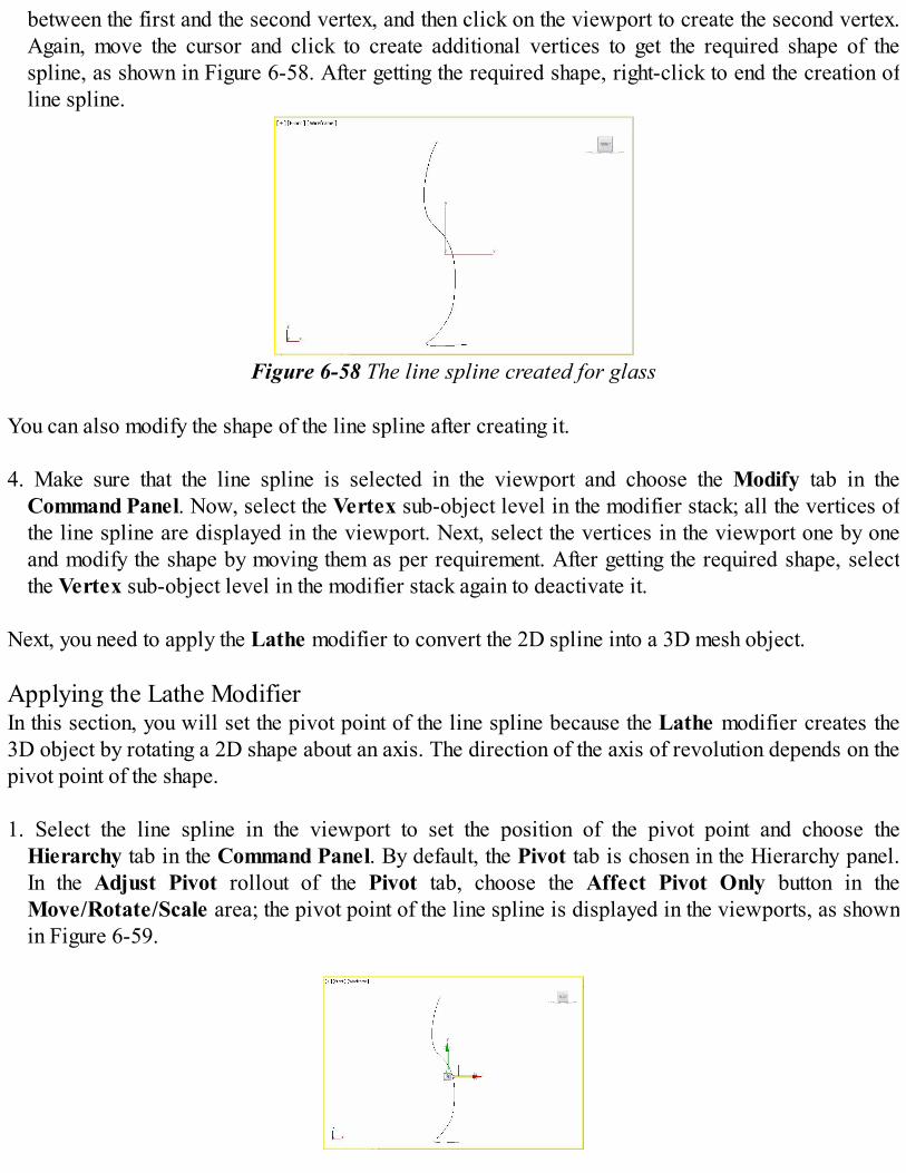
between the first and the second vertex, and then click on the viewport to create the second vertex.Again, move the cursor and click to create additional vertices to get the required shape of thespline, as shown in Figure 6-58. After getting the required shape, right-click to end the creation ofline spline.
Figure 6-58 The line spline created for glass You can also modify the shape of the line spline after creating it. 4. Make sure that the line spline is selected in the viewport and choose the Modify tab in the
Command Panel. Now, select the Vertex sub-object level in the modifier stack; all the vertices ofthe line spline are displayed in the viewport. Next, select the vertices in the viewport one by oneand modify the shape by moving them as per requirement. After getting the required shape, selectthe Vertex sub-object level in the modifier stack again to deactivate it.
Next, you need to apply the Lathe modifier to convert the 2D spline into a 3D mesh object.
Applying the Lathe ModifierIn this section, you will set the pivot point of the line spline because the Lathe modifier creates the3D object by rotating a 2D shape about an axis. The direction of the axis of revolution depends on thepivot point of the shape. 1. Select the line spline in the viewport to set the position of the pivot point and choose the
Hierarchy tab in the Command Panel. By default, the Pivot tab is chosen in the Hierarchy panel.In the Adjust Pivot rollout of the Pivot tab, choose the Affect Pivot Only button in theMove/Rotate/Scale area; the pivot point of the line spline is displayed in the viewports, as shownin Figure 6-59.

Figure 6-59 The pivot point of the line spline at its original position 2. In the Front viewport, move the pivot point on the first vertex of the line spline using the Select
and Move tool, as shown in Figure 6-60. Now, choose the Affect Pivot Only button again todeactivate it; the pivot point disappears.
Figure 6-60 The pivot point after adjusting its position in the Front viewport
NoteWhile applying the Lathe modifier, you can also select the first vertex of the line spline instead ofadjusting its pivot point, as shown in Figure 6-61.
Figure 6-61 The first vertex selected in the line spline
3. Make sure that the line spline is selected in the viewport and choose Modifiers > Patch/SplineEditing > Lathe from the menu bar; the 2D line spline is converted into the 3D mesh object. Also,the Parameters rollout is displayed in the Modify panel.
4. In the Parameters rollout, select the Flip Normals check box.
5. Name the new 3D object as glass. Next, click on the Modifier List drop-down list and select Shell
from it; the Shell modifier is applied to glass. 6. In the Parameters rollout, set the value 1.5 in the Inner Amount spinner. 7. Next, click anywhere in the viewport to deselect glass. Choose the Zoom Extents All tool; glass
is displayed in the viewports, as shown in Figure 6-62.
8. Create a copy of glass in the Front viewport to make a pair and then choose the Zoom Extents Alltool; a pair of cocktail glasses is displayed in the viewports, as shown in Figure 6-63.

Figure 6-62 The glass geometry displayed in viewports
Figure 6-63 A pair of glasses in viewports
Assigning the Material to GlassesIn this section, you will assign materials to the pair of glasses. 1. Choose Rendering > Material Editor > Compact Material Editor
from the menu bar; the Material Editor dialog box is displayed, refer toFigure 6-64.
2. Select the 01 - Default sample slot in the Material Editor dialog box,
if it is not already selected. Now, in the Shader Basic Parametersrollout, select the 2-Sided check box to apply the material on both sidesof the faces, as shown in Figure 6-64.
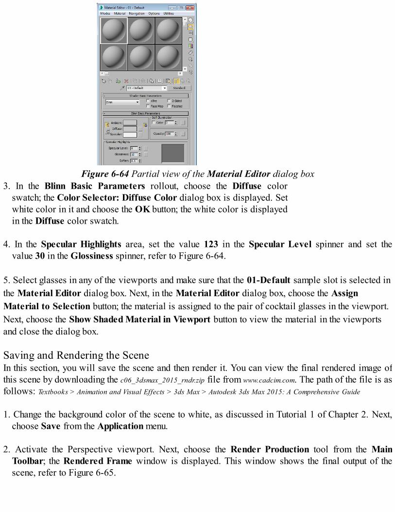
Figure 6-64 Partial view of the Material Editor dialog box
3. In the Blinn Basic Parameters rollout, choose the Diffuse colorswatch; the Color Selector: Diffuse Color dialog box is displayed. Setwhite color in it and choose the OK button; the white color is displayedin the Diffuse color swatch.
4. In the Specular Highlights area, set the value 123 in the Specular Level spinner and set the
value 30 in the Glossiness spinner, refer to Figure 6-64.
5. Select glasses in any of the viewports and make sure that the 01-Default sample slot is selected inthe Material Editor dialog box. Next, in the Material Editor dialog box, choose the AssignMaterial to Selection button; the material is assigned to the pair of cocktail glasses in the viewport.Next, choose the Show Shaded Material in Viewport button to view the material in the viewportsand close the dialog box.
Saving and Rendering the SceneIn this section, you will save the scene and then render it. You can view the final rendered image ofthis scene by downloading the c06_3dsmax_2015_rndr.zip file from www.cadcim.com. The path of the file is asfollows: Textbooks > Animation and Visual Effects > 3ds Max > Autodesk 3ds Max 2015: A Comprehensive Guide 1. Change the background color of the scene to white, as discussed in Tutorial 1 of Chapter 2. Next,
choose Save from the Application menu. 2. Activate the Perspective viewport. Next, choose the Render Production tool from the Main
Toolbar; the Rendered Frame window is displayed. This window shows the final output of thescene, refer to Figure 6-65.

Figure 6-65 The glass models in the final output after rendering
Tutorial 2In this tutorial, you will create the model of a vase with flower plant, by converting a 2D spline into a3D mesh object, as shown in Figure 6-66. (Expected time: 25 min)
Figure 6-66 The model of a vase with flower plant
The following steps are required to complete this tutorial: a. Create the project folder.b. Create a line spline for the vase.c. Apply the Lathe modifier.d. Assign the material to the vase.e. Create a stand for the vase.f. Save and render the scene. Creating the Project FolderCreate a new project folder with the name c06_tut2 at \Documents\3dsmax2015 and then save the filewith the name c06tut2, as discussed in Tutorial 1 of Chapter 2. Creating a Line Spline for the VaseIn this section, you will create a shape similar to the half portion of the vase using the Line tool. 1. Activate the Front viewport and choose Create > Shapes in the Command Panel; the Splines

option is selected by default in the drop-down list below the Shapes button. Now, choose the Linetool from the Object Type rollout.
2. In the Creation Method rollout, select the Corner radio button in the Initial Type and Drag Type
areas.3. Create a line spline as discussed in Tutorial 1. This spline should be similar to the half portion of
the vase, refer to Figure 6-67. 4. Choose the Modify tab and select the Vertex sub-object level in the modifier stack; all vertices of
the line spline are displayed in the viewport. Next, select the vertices one by one in the viewportand modify the shape by moving them to get a perfect shape.
Applying the Lathe ModifierIn this section, you will apply the Lathe modifier to convert the 2D spline into the 3D mesh object. 1. Select the first vertex of the spline in the Front viewport, as shown in Figure 6-68.
Figure 6-67 A line spline created for the vase
Figure 6-68 The first vertex of the line spline selected in the Front viewport
2. Choose Modifiers > Patch/Spline Editing > Lathe from the menu bar; the 2D line spline isconverted into a 3D mesh object.
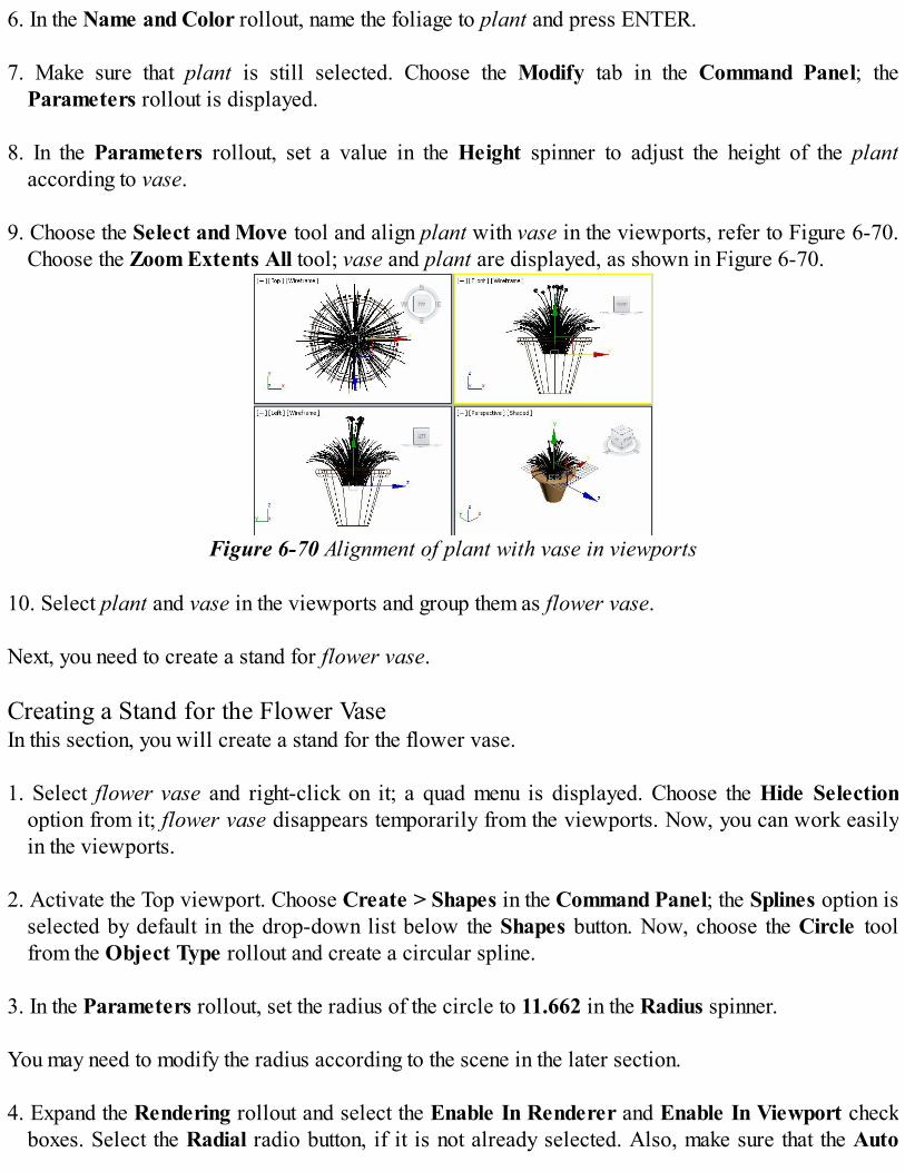
3. Name the new 3D mesh object as vase. Also, click anywhere in the viewport to deselect the vase. 4. Choose the Zoom Extents All tool; the entire vase is displayed in the viewports, as shown in
Figure 6-69.
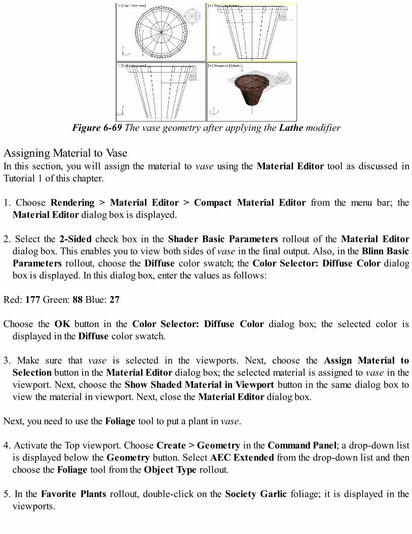
Figure 6-69 The vase geometry after applying the Lathe modifier Assigning Material to VaseIn this section, you will assign the material to vase using the Material Editor tool as discussed inTutorial 1 of this chapter. 1. Choose Rendering > Material Editor > Compact Material Editor from the menu bar; the
Material Editor dialog box is displayed. 2. Select the 2-Sided check box in the Shader Basic Parameters rollout of the Material Editor
dialog box. This enables you to view both sides of vase in the final output. Also, in the Blinn BasicParameters rollout, choose the Diffuse color swatch; the Color Selector: Diffuse Color dialogbox is displayed. In this dialog box, enter the values as follows:
Red: 177 Green: 88 Blue: 27 Choose the OK button in the Color Selector: Diffuse Color dialog box; the selected color is
displayed in the Diffuse color swatch.
3. Make sure that vase is selected in the viewports. Next, choose the Assign Material toSelection button in the Material Editor dialog box; the selected material is assigned to vase in theviewport. Next, choose the Show Shaded Material in Viewport button in the same dialog box toview the material in viewport. Next, close the Material Editor dialog box.
Next, you need to use the Foliage tool to put a plant in vase. 4. Activate the Top viewport. Choose Create > Geometry in the Command Panel; a drop-down list
is displayed below the Geometry button. Select AEC Extended from the drop-down list and thenchoose the Foliage tool from the Object Type rollout.
5. In the Favorite Plants rollout, double-click on the Society Garlic foliage; it is displayed in the
viewports.
6. In the Name and Color rollout, name the foliage to plant and press ENTER. 7. Make sure that plant is still selected. Choose the Modify tab in the Command Panel; the
Parameters rollout is displayed. 8. In the Parameters rollout, set a value in the Height spinner to adjust the height of the plant
according to vase. 9. Choose the Select and Move tool and align plant with vase in the viewports, refer to Figure 6-70.
Choose the Zoom Extents All tool; vase and plant are displayed, as shown in Figure 6-70.
Figure 6-70 Alignment of plant with vase in viewports
10. Select plant and vase in the viewports and group them as flower vase. Next, you need to create a stand for flower vase. Creating a Stand for the Flower VaseIn this section, you will create a stand for the flower vase. 1. Select flower vase and right-click on it; a quad menu is displayed. Choose the Hide Selection
option from it; flower vase disappears temporarily from the viewports. Now, you can work easilyin the viewports.
2. Activate the Top viewport. Choose Create > Shapes in the Command Panel; the Splines option is
selected by default in the drop-down list below the Shapes button. Now, choose the Circle toolfrom the Object Type rollout and create a circular spline.
3. In the Parameters rollout, set the radius of the circle to 11.662 in the Radius spinner. You may need to modify the radius according to the scene in the later section.
4. Expand the Rendering rollout and select the Enable In Renderer and Enable In Viewport checkboxes. Select the Radial radio button, if it is not already selected. Also, make sure that the Auto
Smooth check box is selected. Now, enter the values as follows: Thickness: 2.0 Sides: 15 Angle: 0.99
5. The circular spline is automatically named as Circle001. Now, change its color by entering thevalues as follows:
Red: 193 Green: 193 Blue: 193 6. Create another circle in the Top viewport. It is automatically named as Circle002.
7. In the Parameters rollout, set the radius value of Circle002, which should be just the double theradius value of Circle001.
8. Change the color of Circle002 to black.
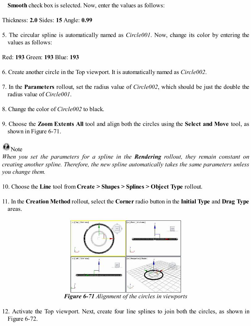
9. Choose the Zoom Extents All tool and align both the circles using the Select and Move tool, asshown in Figure 6-71.
NoteWhen you set the parameters for a spline in the Rendering rollout, they remain constant oncreating another spline. Therefore, the new spline automatically takes the same parameters unlessyou change them. 10. Choose the Line tool from Create > Shapes > Splines > Object Type rollout.
11. In the Creation Method rollout, select the Corner radio button in the Initial Type and Drag Typeareas.
Figure 6-71 Alignment of the circles in viewports
12. Activate the Top viewport. Next, create four line splines to join both the circles, as shown inFigure 6-72.
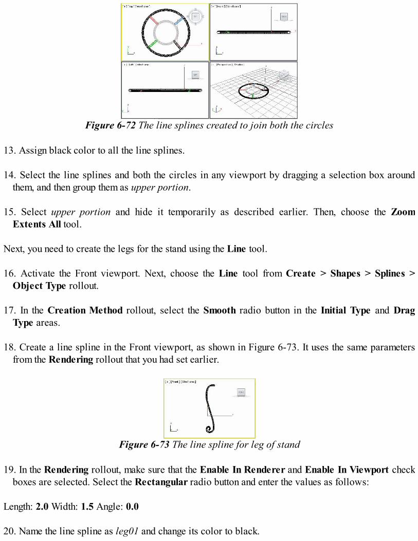
Figure 6-72 The line splines created to join both the circles
13. Assign black color to all the line splines.
14. Select the line splines and both the circles in any viewport by dragging a selection box aroundthem, and then group them as upper portion.
15. Select upper portion and hide it temporarily as described earlier. Then, choose the Zoom
Extents All tool. Next, you need to create the legs for the stand using the Line tool. 16. Activate the Front viewport. Next, choose the Line tool from Create > Shapes > Splines >
Object Type rollout. 17. In the Creation Method rollout, select the Smooth radio button in the Initial Type and Drag
Type areas. 18. Create a line spline in the Front viewport, as shown in Figure 6-73. It uses the same parameters
from the Rendering rollout that you had set earlier.
Figure 6-73 The line spline for leg of stand
19. In the Rendering rollout, make sure that the Enable In Renderer and Enable In Viewport checkboxes are selected. Select the Rectangular radio button and enter the values as follows:
Length: 2.0 Width: 1.5 Angle: 0.0
20. Name the line spline as leg01 and change its color to black.

21. Right-click in any of the viewports; a quad menu is displayed. Choose the Unhide by Name
option; the Unhide Objects dialog box is displayed. Select upper portion from the list given inthis dialog box and choose the Unhide button; upper portion is now displayed in the viewport.Choose the Zoom Extents All tool.
NoteYou can resize leg01 according to the size of the upper portion using the Select and Uniform Scaletool.
22. Align upper portion and leg01 in viewports, as shown in Figure 6-74.
Figure 6-74 Alignment of upper portion and leg01 in viewports
Next, you need to copy the leg01 to create other legs. 23. Create three copies of leg01; they are automatically named as leg002, leg003, and leg004. 24. Align leg01, leg002, leg003, and leg004 using the Select and Move and Select and Rotate
tools, as shown in Figure 6-75. 25. Select all the objects in the viewport and group them as vase stand.
26. Right-click on the viewport; a quad menu is displayed. Choose the Unhide All option; all the
hidden objects are displayed in the viewports.
27. Align flower vase and vase stand and choose the Zoom Extents All tool, refer to Figure 6-76.
NoteYou can adjust the size of the flower vase according to the size of the vase stand using the Selectand Uniform Scale tool.

Figure 6-75 Alignment of leg01, leg002, leg003, and leg004 in viewports
Figure 6-76 Alignment of flower vase and vase stand in viewports Saving and Rendering the SceneIn this section, you will save the scene and then render it. 1. Change the background color of the scene to white, as discussed in Tutorial 1 of Chapter 2. 2. Choose Save from the Application menu. 3. Activate the Perspective viewport. Next, choose the Render Production tool from the Main
Toolbar; the Rendered Frame window is displayed. This window shows the final output of thescene, refer to Figure 6-66.

![ニンテンドー3DS LL 取扱説明書 › support › 3ds › pdf › 3dsll... · ニンテンドー3ds ll本体 1台 [spr-001(jpn)] ニンテンドー3ds ll専用タッチペン](https://img.pdfslide.net/doc/110x75/5f190b3ecf3ee0014d14a6ce/ffffff3ds-ll-e-a-support-a-3ds-a-pdf-a-3dsll.jpg)