Embed Size (px)
Citation preview
Autodesk® Topobase™
Autodesk® Topobase™
Developer’s Guide
April 2010
© 2010 Autodesk, Inc. All Rights Reserved. Except as otherwise permitted by Autodesk, Inc., this publication, or parts thereof, may not bereproduced in any form, by any method, for any purpose. Certain materials included in this publication are reprinted with the permission of the copyright holder. TrademarksThe following are registered trademarks or trademarks of Autodesk, Inc., and/or its subsidiaries and/or affiliates in the USA and other countries:3DEC (design/logo), 3December, 3December.com, 3ds Max, Algor, Alias, Alias (swirl design/logo), AliasStudio, Alias|Wavefront (design/logo),ATC, AUGI, AutoCAD, AutoCAD Learning Assistance, AutoCAD LT, AutoCAD Simulator, AutoCAD SQL Extension, AutoCAD SQL Interface,Autodesk, Autodesk Envision, Autodesk Intent, Autodesk Inventor, Autodesk Map, Autodesk MapGuide, Autodesk Streamline, AutoLISP, AutoSnap,AutoSketch, AutoTrack, Backburner, Backdraft, Built with ObjectARX (logo), Burn, Buzzsaw, CAiCE, Civil 3D, Cleaner, Cleaner Central, ClearScale,Colour Warper, Combustion, Communication Specification, Constructware, Content Explorer, Dancing Baby (image), DesignCenter, DesignDoctor, Designer's Toolkit, DesignKids, DesignProf, DesignServer, DesignStudio, Design Web Format, Discreet, DWF, DWG, DWG (logo), DWGExtreme, DWG TrueConvert, DWG TrueView, DXF, Ecotect, Exposure, Extending the Design Team, Face Robot, FBX, Fempro, Fire, Flame, Flare,Flint, FMDesktop, Freewheel, GDX Driver, Green Building Studio, Heads-up Design, Heidi, HumanIK, IDEA Server, i-drop, ImageModeler, iMOUT,Incinerator, Inferno, Inventor, Inventor LT, Kaydara, Kaydara (design/logo), Kynapse, Kynogon, LandXplorer, Lustre, MatchMover, Maya,Mechanical Desktop, Moldflow, Moonbox, MotionBuilder, Movimento, MPA, MPA (design/logo), Moldflow Plastics Advisers, MPI, MoldflowPlastics Insight, MPX, MPX (design/logo), Moldflow Plastics Xpert, Mudbox, Multi-Master Editing, Navisworks, ObjectARX, ObjectDBX, OpenReality, Opticore, Opticore Opus, Pipeplus, PolarSnap, PortfolioWall, Powered with Autodesk Technology, Productstream, ProjectPoint, ProMaterials,RasterDWG, RealDWG, Real-time Roto, Recognize, Render Queue, Retimer,Reveal, Revit, Showcase, ShowMotion, SketchBook, Smoke, Softimage,Softimage|XSI (design/logo), Sparks, SteeringWheels, Stitcher, Stone, StudioTools, ToolClip, Topobase, Toxik, TrustedDWG, ViewCube, Visual,Visual LISP, Volo, Vtour, Wire, Wiretap, WiretapCentral, XSI, and XSI (design/logo). All other brand names, product names or trademarks belong to their respective holders. DisclaimerTHIS PUBLICATION AND THE INFORMATION CONTAINED HEREIN IS MADE AVAILABLE BY AUTODESK, INC. "AS IS." AUTODESK, INC. DISCLAIMSALL WARRANTIES, EITHER EXPRESS OR IMPLIED, INCLUDING BUT NOT LIMITED TO ANY IMPLIED WARRANTIES OF MERCHANTABILITY ORFITNESS FOR A PARTICULAR PURPOSE REGARDING THESE MATERIALS. Published by:Autodesk, Inc.111 McInnis ParkwaySan Rafael, CA 94903, USA
Contents
Chapter 1 Introduction . . . . . . . . . . . . . . . . . . . . . . . . . . . . 1What This Guide Covers . . . . . . . . . . . . . . . . . . . . . . . . . . 1What is Autodesk Topobase? . . . . . . . . . . . . . . . . . . . . . . . . 2Preparing to Run the Examples . . . . . . . . . . . . . . . . . . . . . . . 2Creating Your First Plugin . . . . . . . . . . . . . . . . . . . . . . . . . 3Autodesk Topobase and Visual Studio . . . . . . . . . . . . . . . . . . . 3
Installing Project and Item Templates . . . . . . . . . . . . . . . . 3Installing User Controls . . . . . . . . . . . . . . . . . . . . . . . 5
Chapter 2 New and Changed API Content in Topobase 2011 . . . . . . . . 7Structure Updates . . . . . . . . . . . . . . . . . . . . . . . . . . . . . . 7
Structure Update PlugIns . . . . . . . . . . . . . . . . . . . . . . . 8Derived classes of
Topobase.Update.DocumentStructureUpdatePlugIn . . . . . 9Topobase.Update.StructureUpdateVersionBase . . . . . . . . 9
XML-Based Data Models . . . . . . . . . . . . . . . . . . . . . . 10Overview . . . . . . . . . . . . . . . . . . . . . . . . . . . 10Important Rules . . . . . . . . . . . . . . . . . . . . . . . . 11Example Project . . . . . . . . . . . . . . . . . . . . . . . . 12
Database Support . . . . . . . . . . . . . . . . . . . . . . . . . . . . . 21ConnectionIdentifier . . . . . . . . . . . . . . . . . . . . . . . . . . . 22
Connection . . . . . . . . . . . . . . . . . . . . . . . . . . . . . 22Topobase.Data.Sys.Document . . . . . . . . . . . . . . . . . . . . 23
iii
Spatial Reference Identifier (SRID) . . . . . . . . . . . . . . . . . . . . 23SQL92 . . . . . . . . . . . . . . . . . . . . . . . . . . . . . . . . . . . 24
Tables and Indexes . . . . . . . . . . . . . . . . . . . . . . . . . 25Sequences . . . . . . . . . . . . . . . . . . . . . . . . . . . . . . 27Select Data / Query Class . . . . . . . . . . . . . . . . . . . . . . 27ISqlBuilder (Topobase.Data.DAL.ISqlBuilder) . . . . . . . . . . . . 33
DECODE() . . . . . . . . . . . . . . . . . . . . . . . . . . . 33Command Parameters . . . . . . . . . . . . . . . . . . . . . . . . 35
Orientation . . . . . . . . . . . . . . . . . . . . . . . . . . . . . . . . 35P lo t . . . . . . . . . . . . . . . . . . . . . . . . . . . . . . . . . . . . 36Server API Changes . . . . . . . . . . . . . . . . . . . . . . . . . . . . 37
TBINTERSECTION Package . . . . . . . . . . . . . . . . . . . . . 37Customer-Defined Exceptions on Oracle Database
Server . . . . . . . . . . . . . . . . . . . . . . . . . . . . 39AutoCAD Map 3D Assembly References . . . . . . . . . . . . . . . . . 39Extension Methods (.NET 3.5) . . . . . . . . . . . . . . . . . . . . . . 39API Samples . . . . . . . . . . . . . . . . . . . . . . . . . . . . . . . . 40Obsolete or Deprecated APIs . . . . . . . . . . . . . . . . . . . . . . . 40
Chapter 3 API Overview . . . . . . . . . . . . . . . . . . . . . . . . . . . 43Database . . . . . . . . . . . . . . . . . . . . . . . . . . . . . . . . . . 43
Connecting to the Database . . . . . . . . . . . . . . . . . . . . 43Creating a New Database User . . . . . . . . . . . . . . . . . . . 44
Feature Classes . . . . . . . . . . . . . . . . . . . . . . . . . . . . . . . 47About Feature Classes . . . . . . . . . . . . . . . . . . . . . . . . 47Topics . . . . . . . . . . . . . . . . . . . . . . . . . . . . . . . . 47Creating Feature Classes . . . . . . . . . . . . . . . . . . . . . . . 48Feature Class Types . . . . . . . . . . . . . . . . . . . . . . . . . 49Attributes . . . . . . . . . . . . . . . . . . . . . . . . . . . . . . 50Events . . . . . . . . . . . . . . . . . . . . . . . . . . . . . . . . 51Feature Class Sample Code . . . . . . . . . . . . . . . . . . . . . 53
Features . . . . . . . . . . . . . . . . . . . . . . . . . . . . . . . . . . 55About Features . . . . . . . . . . . . . . . . . . . . . . . . . . . . 55Creating Features . . . . . . . . . . . . . . . . . . . . . . . . . . 56
Geometry . . . . . . . . . . . . . . . . . . . . . . . . . . . . . . . . . 56Graphic Namespace . . . . . . . . . . . . . . . . . . . . . . . . . 57
Geometries . . . . . . . . . . . . . . . . . . . . . . . . . . 57Accessing the Geometry Property of a Feature . . . . . . . . 58
PlaneGeometry Namespace . . . . . . . . . . . . . . . . . . . . . 61Overview of PlaneGeometry . . . . . . . . . . . . . . . . . 61Creating PlaneGeometry Objects From Graphic
Objects . . . . . . . . . . . . . . . . . . . . . . . . . . . . 63Moving, Scaling, and Rotating PlaneGeometry
Objects . . . . . . . . . . . . . . . . . . . . . . . . . . . . 64SpaceGeometry Namespace . . . . . . . . . . . . . . . . . . . . . 66
Overview of SpaceGeometry . . . . . . . . . . . . . . . . . 66
iv | Contents
Creating SpaceGeometry Objects From GraphicObjects . . . . . . . . . . . . . . . . . . . . . . . . . . . . 68
Creating Graphic Objects From Geometry . . . . . . . . . . . . . 69Topologies . . . . . . . . . . . . . . . . . . . . . . . . . . . . . . . . . 69
Topology Related Assemblies . . . . . . . . . . . . . . . . . . . . 70Logical Topologies . . . . . . . . . . . . . . . . . . . . . . . . . . 70
LogicalTopology as Namespace and Class . . . . . . . . . . 71Initializing Logical Topologies . . . . . . . . . . . . . . . . 71
Area Topologies . . . . . . . . . . . . . . . . . . . . . . . . . . . 72Initializing Area Topologies . . . . . . . . . . . . . . . . . . 72
Chapter 4 Quick Guide: Creating a Topobase Plugin . . . . . . . . . . . . 75Introduction . . . . . . . . . . . . . . . . . . . . . . . . . . . . . . . . 75Creating a New Project . . . . . . . . . . . . . . . . . . . . . . . . . . 76Accessing the Project Properties . . . . . . . . . . . . . . . . . . . . . . 77Configuring the Project to Write the Build Outputs to the Topobase
Bin Folder . . . . . . . . . . . . . . . . . . . . . . . . . . . . . . . . 78Configuring the Project to Run Topobase from Visual Studio . . . . . . 79Adding References To Your Project . . . . . . . . . . . . . . . . . . . . 80Inspecting the Assembly Information . . . . . . . . . . . . . . . . . . 81Adding Code To The Default Class . . . . . . . . . . . . . . . . . . . . 81Creating a Topobase Plugin Definition File . . . . . . . . . . . . . . . . 83Testing the Plugin . . . . . . . . . . . . . . . . . . . . . . . . . . . . . 84
Chapter 5 Creating Application Modules . . . . . . . . . . . . . . . . . . 87Creating the Data Model . . . . . . . . . . . . . . . . . . . . . . . . . 87
About Data Models . . . . . . . . . . . . . . . . . . . . . . . . . 87Creating the Structure Update Plugin . . . . . . . . . . . . . . . . 88Creating an Update Version Module . . . . . . . . . . . . . . . . 92
Adding Changes to the Data Model . . . . . . . . . . . . . 96Data Model Elements . . . . . . . . . . . . . . . . . . . . . . . 100
Topics . . . . . . . . . . . . . . . . . . . . . . . . . . . . 100Feature Classes . . . . . . . . . . . . . . . . . . . . . . . . 100Labels . . . . . . . . . . . . . . . . . . . . . . . . . . . . 101Attributes . . . . . . . . . . . . . . . . . . . . . . . . . . . 101Attribute Relations . . . . . . . . . . . . . . . . . . . . . . 102Domains . . . . . . . . . . . . . . . . . . . . . . . . . . . 103Utility Model . . . . . . . . . . . . . . . . . . . . . . . . . 104Client-Side Feature Rules . . . . . . . . . . . . . . . . . . 104Workflows . . . . . . . . . . . . . . . . . . . . . . . . . . 105
Installing an Application With a Structure Update Plugin . . . . 107Creating a Stand-Alone Autodesk Topobase Extension . . . . . . 107
Adding Feature Rules . . . . . . . . . . . . . . . . . . . . . . . . . . . 107About Feature Rules . . . . . . . . . . . . . . . . . . . . . . . . 107Creating Feature Rules . . . . . . . . . . . . . . . . . . . . . . . 108
Contents | v
Creating the FeatureRulePlugin Module . . . . . . . . . . 108Creating the Rules . . . . . . . . . . . . . . . . . . . . . . 108Rule Priorities . . . . . . . . . . . . . . . . . . . . . . . . 109Installation . . . . . . . . . . . . . . . . . . . . . . . . . . 110
Creating Workflows . . . . . . . . . . . . . . . . . . . . . . . . . . . 111About Workflows . . . . . . . . . . . . . . . . . . . . . . . . . . 111Workflow Scripts in Autodesk Topobase Administrator . . . . . . 111
Use of the “Me” Object . . . . . . . . . . . . . . . . . . . 112Workflow Plugin . . . . . . . . . . . . . . . . . . . . . . . . . . 113
Create a Workflow Plugin Module . . . . . . . . . . . . . . 114Create a Workflow Pane UI . . . . . . . . . . . . . . . . . 117Acquisition Workflows - Basics of Digitizing . . . . . . . . 128Analysis Workflows - Basics of Analysis . . . . . . . . . . . 130Installation . . . . . . . . . . . . . . . . . . . . . . . . . . 131
Creating User Interface Plugins . . . . . . . . . . . . . . . . . . . . . 133Creating an Application Plugin . . . . . . . . . . . . . . . . . . 134
About Application Plugins . . . . . . . . . . . . . . . . . . 134Responding to Application Events . . . . . . . . . . . . . 135Adding Custom Toolbars and Toolbar Buttons . . . . . . . 136Adding Menu Items . . . . . . . . . . . . . . . . . . . . . 138
Creating a Document Plugin . . . . . . . . . . . . . . . . . . . 139About Document Plugins . . . . . . . . . . . . . . . . . . 139Creating Custom Toolbars and Toolbar Icons . . . . . . . . 140Modifying the Context Menu . . . . . . . . . . . . . . . 142
Creating a Dialog Plugin . . . . . . . . . . . . . . . . . . . . . . 144About Dialog Plugins . . . . . . . . . . . . . . . . . . . . 144Creating Toolbar Items . . . . . . . . . . . . . . . . . . . 145Creating a Menu Bar . . . . . . . . . . . . . . . . . . . . . 145Adding Controls to a Dialog . . . . . . . . . . . . . . . . . 146
Creating an Application Flyin . . . . . . . . . . . . . . . . . . . 147About Application Flyins . . . . . . . . . . . . . . . . . . 147
Creating a Document Flyin . . . . . . . . . . . . . . . . . . . . 149About Document Flyins . . . . . . . . . . . . . . . . . . . 149
Creating a Dialog Flyin . . . . . . . . . . . . . . . . . . . . . . 150About Dialog Flyins . . . . . . . . . . . . . . . . . . . . . 150
User Interaction . . . . . . . . . . . . . . . . . . . . . . . . . . 152Using Forms . . . . . . . . . . . . . . . . . . . . . . . . . 152Autodesk Topobase Forms Controls . . . . . . . . . . . . . 153Progress Bar . . . . . . . . . . . . . . . . . . . . . . . . . 154Message Box and Input Box . . . . . . . . . . . . . . . . . 157
Installation . . . . . . . . . . . . . . . . . . . . . . . . . . . . . 159Plugins and Visual Studio . . . . . . . . . . . . . . . . . . . . . 160
Installing the Project Template . . . . . . . . . . . . . . . 160Installing the Item Templates . . . . . . . . . . . . . . . . 161Installing User Controls . . . . . . . . . . . . . . . . . . . 161
Creating Survey File Format Plugins . . . . . . . . . . . . . . . . . . . 162
vi | Contents
Creating a Survey File Format Module . . . . . . . . . . . . . . 162Implementing StartImport . . . . . . . . . . . . . . . . . . . . . 163
Creating Option Pages . . . . . . . . . . . . . . . . . . . . . . . . . . 166Creating an Option Page Module . . . . . . . . . . . . . . . . . 166Reading and Writing User Settings . . . . . . . . . . . . . . . . 167Installation . . . . . . . . . . . . . . . . . . . . . . . . . . . . . 171
Creating Administrator Pages . . . . . . . . . . . . . . . . . . . . . . 172Creating an Administrator Page Plugin . . . . . . . . . . . . . . 172Responding to Administrator Events . . . . . . . . . . . . . . . 173Installing Administrator Plugins . . . . . . . . . . . . . . . . . . 173
Installation . . . . . . . . . . . . . . . . . . . . . . . . . . . . . . . . 174Building and Installing an Application Module . . . . . . . . . . 174Creating a Document Using the Module . . . . . . . . . . . . . 174Manually Installing a Stand-Alone Workflow . . . . . . . . . . . 177Installing a Stand-Alone Plugin . . . . . . . . . . . . . . . . . . 178
Chapter 6 Developer Samples . . . . . . . . . . . . . . . . . . . . . . . 179Introduction . . . . . . . . . . . . . . . . . . . . . . . . . . . . . . . 179Building The Samples . . . . . . . . . . . . . . . . . . . . . . . . . . 180
Usernames and Passwords . . . . . . . . . . . . . . . . . . . . . 180Topobase Database Server (TBSYS) . . . . . . . . . . . . . . . . . 180
Running The Samples . . . . . . . . . . . . . . . . . . . . . . . . . . 181Common Steps . . . . . . . . . . . . . . . . . . . . . . . . . . . . . . 181Sample Details . . . . . . . . . . . . . . . . . . . . . . . . . . . . . . 182
Sample 01 - Create Structure . . . . . . . . . . . . . . . . . . . . 182Purpose . . . . . . . . . . . . . . . . . . . . . . . . . . . . 182Procedure . . . . . . . . . . . . . . . . . . . . . . . . . . 182Create a Workspace . . . . . . . . . . . . . . . . . . . . . 185Create a Drawing Template . . . . . . . . . . . . . . . . . 187
Sample 02 - Read/Write Features . . . . . . . . . . . . . . . . . . 191Purpose . . . . . . . . . . . . . . . . . . . . . . . . . . . . 191Procedure . . . . . . . . . . . . . . . . . . . . . . . . . . 191
Sample 03 - Oracle Data Provider (ODP) .Net . . . . . . . . . . . 193Purpose . . . . . . . . . . . . . . . . . . . . . . . . . . . . 193Procedure . . . . . . . . . . . . . . . . . . . . . . . . . . 193
Sample 10 - Document Context Menu . . . . . . . . . . . . . . 195Purpose . . . . . . . . . . . . . . . . . . . . . . . . . . . . 195Procedure . . . . . . . . . . . . . . . . . . . . . . . . . . 195
Sample 12 - Document Toolbar Button . . . . . . . . . . . . . . 196Purpose . . . . . . . . . . . . . . . . . . . . . . . . . . . . 196Procedure . . . . . . . . . . . . . . . . . . . . . . . . . . 196
Sample 13 - Dialog Toolbar Button . . . . . . . . . . . . . . . . 198Purpose . . . . . . . . . . . . . . . . . . . . . . . . . . . . 198Procedure . . . . . . . . . . . . . . . . . . . . . . . . . . 198
Sample 14 - Main Menu . . . . . . . . . . . . . . . . . . . . . . 199Purpose . . . . . . . . . . . . . . . . . . . . . . . . . . . . 199
Contents | vii
Procedure . . . . . . . . . . . . . . . . . . . . . . . . . . 199Sample 15 - Main Toolbar . . . . . . . . . . . . . . . . . . . . . 201
Purpose . . . . . . . . . . . . . . . . . . . . . . . . . . . . 201Procedure . . . . . . . . . . . . . . . . . . . . . . . . . . 201
Sample 16 - Dialog Button . . . . . . . . . . . . . . . . . . . . . 203Purpose . . . . . . . . . . . . . . . . . . . . . . . . . . . . 203Procedure . . . . . . . . . . . . . . . . . . . . . . . . . . 203
Sample 17 - Dialog Menu . . . . . . . . . . . . . . . . . . . . . 206Purpose . . . . . . . . . . . . . . . . . . . . . . . . . . . . 206Procedure . . . . . . . . . . . . . . . . . . . . . . . . . . 206
Sample 18 - Dialog Events . . . . . . . . . . . . . . . . . . . . . 207Purpose . . . . . . . . . . . . . . . . . . . . . . . . . . . . 207Procedure . . . . . . . . . . . . . . . . . . . . . . . . . . 207
Sample 19 - Input Box, Confirm Box, and Multiple InputBox . . . . . . . . . . . . . . . . . . . . . . . . . . . . . . . . 208
Purpose . . . . . . . . . . . . . . . . . . . . . . . . . . . . 208Procedure . . . . . . . . . . . . . . . . . . . . . . . . . . 209
Sample 20 - Forms and Controls . . . . . . . . . . . . . . . . . . 210Purpose . . . . . . . . . . . . . . . . . . . . . . . . . . . . 210Procedure . . . . . . . . . . . . . . . . . . . . . . . . . . 210
Sample 22 - Document Flyin . . . . . . . . . . . . . . . . . . . 211Purpose . . . . . . . . . . . . . . . . . . . . . . . . . . . . 211Procedure . . . . . . . . . . . . . . . . . . . . . . . . . . 211
Sample 25 - Progress Bar . . . . . . . . . . . . . . . . . . . . . . 213Purpose . . . . . . . . . . . . . . . . . . . . . . . . . . . . 213Procedure . . . . . . . . . . . . . . . . . . . . . . . . . . 213
Sample 28 - List Box With Context Menu . . . . . . . . . . . . . 214Purpose . . . . . . . . . . . . . . . . . . . . . . . . . . . . 214Procedure . . . . . . . . . . . . . . . . . . . . . . . . . . 214
Sample 29 - Tree View . . . . . . . . . . . . . . . . . . . . . . . 215Purpose . . . . . . . . . . . . . . . . . . . . . . . . . . . . 215Procedure . . . . . . . . . . . . . . . . . . . . . . . . . . 215
Sample 30 - Map Button . . . . . . . . . . . . . . . . . . . . . . 216Purpose . . . . . . . . . . . . . . . . . . . . . . . . . . . . 216Procedure . . . . . . . . . . . . . . . . . . . . . . . . . . 216
Sample 31 - List Box . . . . . . . . . . . . . . . . . . . . . . . . 217Purpose . . . . . . . . . . . . . . . . . . . . . . . . . . . . 217Procedure . . . . . . . . . . . . . . . . . . . . . . . . . . 218
Sample 32 - Highlight . . . . . . . . . . . . . . . . . . . . . . . 218Purpose . . . . . . . . . . . . . . . . . . . . . . . . . . . . 218Procedure . . . . . . . . . . . . . . . . . . . . . . . . . . 219
Sample 33 - Information . . . . . . . . . . . . . . . . . . . . . . 220Purpose . . . . . . . . . . . . . . . . . . . . . . . . . . . . 220Procedure . . . . . . . . . . . . . . . . . . . . . . . . . . 220
Sample 34 - File Upload and Download . . . . . . . . . . . . . . 221Purpose . . . . . . . . . . . . . . . . . . . . . . . . . . . . 221
viii | Contents
Procedure . . . . . . . . . . . . . . . . . . . . . . . . . . 221Sample 37 - Windows Menu Items . . . . . . . . . . . . . . . . 222
Purpose . . . . . . . . . . . . . . . . . . . . . . . . . . . . 222Procedure . . . . . . . . . . . . . . . . . . . . . . . . . . 222
Sample 40 - Create All Dialogs Boxes . . . . . . . . . . . . . . . 224Purpose . . . . . . . . . . . . . . . . . . . . . . . . . . . . 224Procedure . . . . . . . . . . . . . . . . . . . . . . . . . . 224
Sample 41 - Grid Control . . . . . . . . . . . . . . . . . . . . . 225Purpose . . . . . . . . . . . . . . . . . . . . . . . . . . . . 225Procedure . . . . . . . . . . . . . . . . . . . . . . . . . . 225
Sample 43 - Dialog Box Validation . . . . . . . . . . . . . . . . 226Purpose . . . . . . . . . . . . . . . . . . . . . . . . . . . . 226Procedure . . . . . . . . . . . . . . . . . . . . . . . . . . 226
Sample 44 - Menus and Toolbars . . . . . . . . . . . . . . . . . 228Purpose . . . . . . . . . . . . . . . . . . . . . . . . . . . . 228Procedure . . . . . . . . . . . . . . . . . . . . . . . . . . 228
Sample 45 - Matrix . . . . . . . . . . . . . . . . . . . . . . . . . 228Purpose . . . . . . . . . . . . . . . . . . . . . . . . . . . . 228Procedure . . . . . . . . . . . . . . . . . . . . . . . . . . 229
Sample 46 - Interaction with a Map . . . . . . . . . . . . . . . . 230Purpose . . . . . . . . . . . . . . . . . . . . . . . . . . . . 230Procedure . . . . . . . . . . . . . . . . . . . . . . . . . . 230
Sample 47 - Application Options . . . . . . . . . . . . . . . . . 232Purpose . . . . . . . . . . . . . . . . . . . . . . . . . . . . 232Procedure . . . . . . . . . . . . . . . . . . . . . . . . . . 232
Sample 48 - Treeview With Context Menu . . . . . . . . . . . . 234Purpose . . . . . . . . . . . . . . . . . . . . . . . . . . . . 234Procedure . . . . . . . . . . . . . . . . . . . . . . . . . . 234
Sample 50 - Date/Time Picker . . . . . . . . . . . . . . . . . . . 235Purpose . . . . . . . . . . . . . . . . . . . . . . . . . . . . 235Procedure . . . . . . . . . . . . . . . . . . . . . . . . . . 235
Sample 51 - File and Directory Text Box . . . . . . . . . . . . . . 236Purpose . . . . . . . . . . . . . . . . . . . . . . . . . . . . 236Procedure . . . . . . . . . . . . . . . . . . . . . . . . . . 236
Sample 52 - Dock In Container . . . . . . . . . . . . . . . . . . 237Purpose . . . . . . . . . . . . . . . . . . . . . . . . . . . . 237Procedure . . . . . . . . . . . . . . . . . . . . . . . . . . 237
Sample 53 - Connection Tools . . . . . . . . . . . . . . . . . . . 240Purpose . . . . . . . . . . . . . . . . . . . . . . . . . . . . 240Procedure . . . . . . . . . . . . . . . . . . . . . . . . . . 241
Sample 55 - Drop Down Buttons . . . . . . . . . . . . . . . . . 243Purpose . . . . . . . . . . . . . . . . . . . . . . . . . . . . 243Procedure . . . . . . . . . . . . . . . . . . . . . . . . . . 244
Sample 56 - List Box . . . . . . . . . . . . . . . . . . . . . . . . 244Purpose . . . . . . . . . . . . . . . . . . . . . . . . . . . . 244Procedure . . . . . . . . . . . . . . . . . . . . . . . . . . 244
Contents | ix
Sample 57 - Special Menu Items . . . . . . . . . . . . . . . . . . 245Purpose . . . . . . . . . . . . . . . . . . . . . . . . . . . . 245Procedure . . . . . . . . . . . . . . . . . . . . . . . . . . 245
Sample 59 - Settings and Document Options . . . . . . . . . . . 246Purpose . . . . . . . . . . . . . . . . . . . . . . . . . . . . 246Procedure . . . . . . . . . . . . . . . . . . . . . . . . . . 246
Sample 61 - Dialog Box User Controls . . . . . . . . . . . . . . . 247Purpose . . . . . . . . . . . . . . . . . . . . . . . . . . . . 247Procedure . . . . . . . . . . . . . . . . . . . . . . . . . . 248
Sample 62 - Control Test . . . . . . . . . . . . . . . . . . . . . . 251Purpose . . . . . . . . . . . . . . . . . . . . . . . . . . . . 251Procedure . . . . . . . . . . . . . . . . . . . . . . . . . . 252
Sample 64 - Desktop Option Pages . . . . . . . . . . . . . . . . 252Purpose . . . . . . . . . . . . . . . . . . . . . . . . . . . . 252Procedure . . . . . . . . . . . . . . . . . . . . . . . . . . 253
Sample 66 - Reports . . . . . . . . . . . . . . . . . . . . . . . . 254Purpose . . . . . . . . . . . . . . . . . . . . . . . . . . . . 254Procedure . . . . . . . . . . . . . . . . . . . . . . . . . . 255
Sample 67 - Dialog Box FlyIn . . . . . . . . . . . . . . . . . . . 257Purpose . . . . . . . . . . . . . . . . . . . . . . . . . . . . 257Procedure . . . . . . . . . . . . . . . . . . . . . . . . . . 257
Sample 68 - Option Page With Tree Nodes . . . . . . . . . . . . 258Purpose . . . . . . . . . . . . . . . . . . . . . . . . . . . . 258Procedure . . . . . . . . . . . . . . . . . . . . . . . . . . 258
Sample 69 - FlyIn Container . . . . . . . . . . . . . . . . . . . . 259Purpose . . . . . . . . . . . . . . . . . . . . . . . . . . . . 259Procedure . . . . . . . . . . . . . . . . . . . . . . . . . . 259
Sample 70 - Application Flyin . . . . . . . . . . . . . . . . . . . 262Purpose . . . . . . . . . . . . . . . . . . . . . . . . . . . . 262Procedure . . . . . . . . . . . . . . . . . . . . . . . . . . 262
Sample 71 - Checked List Box . . . . . . . . . . . . . . . . . . . 263Purpose . . . . . . . . . . . . . . . . . . . . . . . . . . . . 263Procedure . . . . . . . . . . . . . . . . . . . . . . . . . . 263
Sample 72 - Application Toolbar . . . . . . . . . . . . . . . . . . 264Purpose . . . . . . . . . . . . . . . . . . . . . . . . . . . . 264Procedure . . . . . . . . . . . . . . . . . . . . . . . . . . 264
Sample 74 - List Box Multi Selection . . . . . . . . . . . . . . . 265Purpose . . . . . . . . . . . . . . . . . . . . . . . . . . . . 265Procedure . . . . . . . . . . . . . . . . . . . . . . . . . . 265
Sample 75- SQL Export . . . . . . . . . . . . . . . . . . . . . . 266Purpose . . . . . . . . . . . . . . . . . . . . . . . . . . . . 266Procedure . . . . . . . . . . . . . . . . . . . . . . . . . . 266
Sample 77 - Menu Control . . . . . . . . . . . . . . . . . . . . . 267Purpose . . . . . . . . . . . . . . . . . . . . . . . . . . . . 267Procedure . . . . . . . . . . . . . . . . . . . . . . . . . . 267
Sample 78 - Web Browser . . . . . . . . . . . . . . . . . . . . . 268
x | Contents
Purpose . . . . . . . . . . . . . . . . . . . . . . . . . . . . 268Procedure . . . . . . . . . . . . . . . . . . . . . . . . . . 268
Sample 79 - Tab Control . . . . . . . . . . . . . . . . . . . . . . 269Purpose . . . . . . . . . . . . . . . . . . . . . . . . . . . . 269Procedure . . . . . . . . . . . . . . . . . . . . . . . . . . 269
Sample 80 - Canvas Control . . . . . . . . . . . . . . . . . . . . 270Purpose . . . . . . . . . . . . . . . . . . . . . . . . . . . . 270Procedure . . . . . . . . . . . . . . . . . . . . . . . . . . 270
Sample 81 - Dialog Box Control Update . . . . . . . . . . . . . . 271Purpose . . . . . . . . . . . . . . . . . . . . . . . . . . . . 271Procedure . . . . . . . . . . . . . . . . . . . . . . . . . . 271
Sample 83 - Remote Control . . . . . . . . . . . . . . . . . . . . 273Purpose . . . . . . . . . . . . . . . . . . . . . . . . . . . . 273Procedure . . . . . . . . . . . . . . . . . . . . . . . . . . 273
Sample 85 - Workflows . . . . . . . . . . . . . . . . . . . . . . . 275Purpose . . . . . . . . . . . . . . . . . . . . . . . . . . . . 275Procedure . . . . . . . . . . . . . . . . . . . . . . . . . . 275
Sample 86 - Update Plugin . . . . . . . . . . . . . . . . . . . . . 277Purpose . . . . . . . . . . . . . . . . . . . . . . . . . . . . 277Procedure . . . . . . . . . . . . . . . . . . . . . . . . . . 277
Sample 87 - Jobs . . . . . . . . . . . . . . . . . . . . . . . . . . 280Purpose . . . . . . . . . . . . . . . . . . . . . . . . . . . . 280Procedure . . . . . . . . . . . . . . . . . . . . . . . . . . 280
Sample 88 - Features . . . . . . . . . . . . . . . . . . . . . . . . 285Purpose . . . . . . . . . . . . . . . . . . . . . . . . . . . . 285Procedure . . . . . . . . . . . . . . . . . . . . . . . . . . 286
Sample 100 - Map Functions . . . . . . . . . . . . . . . . . . . 288Purpose . . . . . . . . . . . . . . . . . . . . . . . . . . . . 288Procedure . . . . . . . . . . . . . . . . . . . . . . . . . . 288
Sample 102 - Picture Combobox . . . . . . . . . . . . . . . . . 290Purpose . . . . . . . . . . . . . . . . . . . . . . . . . . . . 290Procedure . . . . . . . . . . . . . . . . . . . . . . . . . . 290
Sample 103 - Call Class Via Batch File . . . . . . . . . . . . . . . 291Purpose . . . . . . . . . . . . . . . . . . . . . . . . . . . . 291Procedure . . . . . . . . . . . . . . . . . . . . . . . . . . 291
Sample 104 - Script Engine . . . . . . . . . . . . . . . . . . . . 292Purpose . . . . . . . . . . . . . . . . . . . . . . . . . . . . 292Procedure . . . . . . . . . . . . . . . . . . . . . . . . . . 293
Sample 105 - Create Autodesk Topobase User (Document) . . . . 293Purpose . . . . . . . . . . . . . . . . . . . . . . . . . . . . 293Procedure . . . . . . . . . . . . . . . . . . . . . . . . . . 293
Sample 106 - Unit Support . . . . . . . . . . . . . . . . . . . . . 294Purpose . . . . . . . . . . . . . . . . . . . . . . . . . . . . 294Procedure . . . . . . . . . . . . . . . . . . . . . . . . . . 294
Sample 111 - Feature Explorer . . . . . . . . . . . . . . . . . . . 295Purpose . . . . . . . . . . . . . . . . . . . . . . . . . . . . 295
Contents | xi
Procedure . . . . . . . . . . . . . . . . . . . . . . . . . . 296Sample 112 - Client-Side Feature Rules . . . . . . . . . . . . . . 298
Purpose . . . . . . . . . . . . . . . . . . . . . . . . . . . . 298Procedure . . . . . . . . . . . . . . . . . . . . . . . . . . 298
Sample 116 - Advanced Workflows . . . . . . . . . . . . . . . . 300Purpose . . . . . . . . . . . . . . . . . . . . . . . . . . . . 300Installing the Workflow . . . . . . . . . . . . . . . . . . . 300Procedure . . . . . . . . . . . . . . . . . . . . . . . . . . 301
Sample 117 - Simple Water Module . . . . . . . . . . . . . . . . 302Purpose . . . . . . . . . . . . . . . . . . . . . . . . . . . . 302Procedure . . . . . . . . . . . . . . . . . . . . . . . . . . 303
Sample 118 - Electric Templates . . . . . . . . . . . . . . . . . . 306Purpose . . . . . . . . . . . . . . . . . . . . . . . . . . . . 306Procedure . . . . . . . . . . . . . . . . . . . . . . . . . . 307
Sample 119 - Survey Import Plugin . . . . . . . . . . . . . . . . 310Purpose . . . . . . . . . . . . . . . . . . . . . . . . . . . . 310Procedure . . . . . . . . . . . . . . . . . . . . . . . . . . 311
Sample 120 - Custom URL Invoking . . . . . . . . . . . . . . . 315Purpose . . . . . . . . . . . . . . . . . . . . . . . . . . . . 315Procedure . . . . . . . . . . . . . . . . . . . . . . . . . . 315
Sample 121 - Web Service . . . . . . . . . . . . . . . . . . . . . 315Purpose . . . . . . . . . . . . . . . . . . . . . . . . . . . . 315Procedure . . . . . . . . . . . . . . . . . . . . . . . . . . 315
Sample 122 - Custom Point Numbering . . . . . . . . . . . . . . 316Purpose . . . . . . . . . . . . . . . . . . . . . . . . . . . . 316Procedure . . . . . . . . . . . . . . . . . . . . . . . . . . 316
Sample 123 - Wizard Using WPF . . . . . . . . . . . . . . . . . 319Purpose . . . . . . . . . . . . . . . . . . . . . . . . . . . . 319Procedure . . . . . . . . . . . . . . . . . . . . . . . . . . 319
Sample 124 - Client Plot Commands . . . . . . . . . . . . . . . 322Purpose . . . . . . . . . . . . . . . . . . . . . . . . . . . . 322Procedure . . . . . . . . . . . . . . . . . . . . . . . . . . 322
Sample 125 - Profile . . . . . . . . . . . . . . . . . . . . . . . . 325Purpose . . . . . . . . . . . . . . . . . . . . . . . . . . . . 325Procedure . . . . . . . . . . . . . . . . . . . . . . . . . . 325
Sample 126 - Different Implementations For DifferentDatabases . . . . . . . . . . . . . . . . . . . . . . . . . . . . . 328
Purpose . . . . . . . . . . . . . . . . . . . . . . . . . . . . 328Procedure . . . . . . . . . . . . . . . . . . . . . . . . . . 329
Sample 127 - Login Plugin . . . . . . . . . . . . . . . . . . . . . 330Purpose . . . . . . . . . . . . . . . . . . . . . . . . . . . . 330Procedure . . . . . . . . . . . . . . . . . . . . . . . . . . 330
Sample 128 - Database Independent . . . . . . . . . . . . . . . 333Purpose . . . . . . . . . . . . . . . . . . . . . . . . . . . . 333Procedure . . . . . . . . . . . . . . . . . . . . . . . . . . 333
Sample 129 - Pickfirst Set . . . . . . . . . . . . . . . . . . . . . 341
xii | Contents
Purpose . . . . . . . . . . . . . . . . . . . . . . . . . . . . 341Procedure . . . . . . . . . . . . . . . . . . . . . . . . . . 342
Sample 130 - Schematics . . . . . . . . . . . . . . . . . . . . . . 344Purpose . . . . . . . . . . . . . . . . . . . . . . . . . . . . 344Procedure . . . . . . . . . . . . . . . . . . . . . . . . . . 344
Sample 131 - Web-able User Control . . . . . . . . . . . . . . . 346Purpose . . . . . . . . . . . . . . . . . . . . . . . . . . . . 346Procedure . . . . . . . . . . . . . . . . . . . . . . . . . . 346
Sample 133 - Start Client Via Batch . . . . . . . . . . . . . . . . 347Purpose . . . . . . . . . . . . . . . . . . . . . . . . . . . . 347Procedure . . . . . . . . . . . . . . . . . . . . . . . . . . 347
Sample 135 - Generate Graphics . . . . . . . . . . . . . . . . . . 348Purpose . . . . . . . . . . . . . . . . . . . . . . . . . . . . 348Procedure . . . . . . . . . . . . . . . . . . . . . . . . . . 348
Sample 136 - Extend Plot Editor . . . . . . . . . . . . . . . . . . 349Purpose . . . . . . . . . . . . . . . . . . . . . . . . . . . . 349Procedure . . . . . . . . . . . . . . . . . . . . . . . . . . 349
Sample 140 - Call Report Via URL . . . . . . . . . . . . . . . . . 351Purpose . . . . . . . . . . . . . . . . . . . . . . . . . . . . 351Procedure . . . . . . . . . . . . . . . . . . . . . . . . . . 351
Appendix A TBP File Format . . . . . . . . . . . . . . . . . . . . . . . . . 353Introduction . . . . . . . . . . . . . . . . . . . . . . . . . . . . . . . 353Example TBP Files . . . . . . . . . . . . . . . . . . . . . . . . . . . . 354Plugin Tag Details . . . . . . . . . . . . . . . . . . . . . . . . . . . . 355Property Details . . . . . . . . . . . . . . . . . . . . . . . . . . . . . 356
Appendix B Object Models . . . . . . . . . . . . . . . . . . . . . . . . . . 359Legend . . . . . . . . . . . . . . . . . . . . . . . . . . . . . . . . . . 359Framework . . . . . . . . . . . . . . . . . . . . . . . . . . . . . . . . 361
Data Namespace . . . . . . . . . . . . . . . . . . . . . . . . . . 361Data.Explorer Namespace . . . . . . . . . . . . . . . . . . . . . 363Data.Jobs3 Namespace . . . . . . . . . . . . . . . . . . . . . . . 364Data.Provider Namespace . . . . . . . . . . . . . . . . . . . . . 365Data.Reference and Data.Util.OperationLog Namespaces . . . . 366Data.Sys Namespace . . . . . . . . . . . . . . . . . . . . . . . . 367Graphic Namespace . . . . . . . . . . . . . . . . . . . . . . . . 368Math Namespace . . . . . . . . . . . . . . . . . . . . . . . . . . 369PlaneGeometry Namespace . . . . . . . . . . . . . . . . . . . . 370SpaceGeometry Namespace . . . . . . . . . . . . . . . . . . . . 371Data.Doc.Topologies Namespace . . . . . . . . . . . . . . . . . 372
Workflows . . . . . . . . . . . . . . . . . . . . . . . . . . . . . . . . 373Workflows Namespace . . . . . . . . . . . . . . . . . . . . . . . 373
Area Topology . . . . . . . . . . . . . . . . . . . . . . . . . . . . . . 374AreaTopology Namespace . . . . . . . . . . . . . . . . . . . . . 374
Contents | xiii
LogicalTopology Namespace . . . . . . . . . . . . . . . . . . . . . . . 375Vertical Application Modules . . . . . . . . . . . . . . . . . . . . . . 377
Common Namespace . . . . . . . . . . . . . . . . . . . . . . . 377Electric.Common Namespace . . . . . . . . . . . . . . . . . . . 378
Index . . . . . . . . . . . . . . . . . . . . . . . . . . . . . . . 379
xiv | Contents
Introduction
What This Guide CoversThis guide describes how to use the Autodesk Topobase API and associatedsample code.
It assumes you have read applicable ReadMe files, reviewed appropriateapplication Help (as needed), and are familiar with using Autodesk TopobaseClient or Autodesk Topobase Web. All examples also assume that you haveinstalled the sample data and sample applications supplied with AutodeskTopobase Client, which are included with the default installation package.
For more detailed information about the individual APIs, see the appropriateAutodesk Topobase API References located in the <topobase>\Help directory:
■ Topobase_Client_API.chm
■ Topobase_Modules_API.chm
■ Topobase_ServerSide_API.chm
NOTE The API reference documentaiton is also available in Microsoft Help 2 formatfrom inside Visual Studio (F1).
For more information about administration tasks for Autodesk Topobase, suchas creating and editing data models, setting up users and application options,or customizing feature class forms, see Autodesk Topobase Administrator Guide.
1
1
What is Autodesk Topobase?Autodesk Topobase is an infrastructure asset management solution thatprovides centralized, flexible, and secure access to spatial information forplanning, design, operations and business teams. Built on AutoCAD Map 3D,Autodesk MapGuide Enterprise, and Oracle software, Autodesk Topobase helpsyou see the big picture and make better decisions by integrating CAD, map,asset, GIS and customer information for a more comprehensive view of yourinfrastructure.
Autodesk Topobase Plugins
Plugins play an important role in Autodesk Topobase. They allow you toextend and customize Autodesk Topobase to fit the needs of your organization.For example, they enable customization of the user interface, create and updatedata models, provide management of workspaces, and control how usersinteract with documents and workspaces.
In fact, many of the Autodesk Topobase components are plugins created byAutodesk developers. It enables developers to extend Autodesk Topobase fortheir own needs. To create your own plugin, you need to create a .dll withone or more plugin classes in it and create a .tbp file, which lists the pluginclasses available in the library. See TBP File Format (page 353) for moreinformation.
Preparing to Run the ExamplesAutodesk Topobase provides over 80 samples demonstrating many differentkinds of plugins and showing how to perform simple tasks using the API.These are provided as Microsoft® Visual Studio® 2008 projects in both C# andVisual Basic formats.
The section Developer Samples (page 179) describes how to compile, install,and run the samples, and gives a brief description of what each sample does.The samples are numbered, but since obsolete samples have been removedthe numbers are not always consecutive. Unless otherwise stated, all thesamples can be run in both Autodesk Topobase Client and Autodesk TopobaseWeb Client.
2 | Chapter 1 Introduction
Creating Your First PluginQuick Guide: Creating a Topobase Plugin (page 75) describes how to code,configure, and run a simple C# or Visual Basic user interface plugin project.The process creates an Autodesk Topobase plugin that generates the familiar“Hello World” output. This basic instruction provides a foundation for usingand creating other plugins and for exercising and customizing the manysample applications provided.
Autodesk Topobase and Visual Studio
Installing Project and Item TemplatesAutodesk Topobase includes a project template for creating stand-alone pluginsin Visual Studio 2008. It also includes a series of item templates for addingnew workflows, update plugins, user interface plugins, and other classes andforms to an application module project or stand-alone plugin project.
Installing the Plugin Project Template
Autodesk Topobase includes a generic project template for creating stand-aloneplugin projects in Visual Studio 2008. To install it, copy the project templatenamed CSSimpleTopobasePlugIn.zip from the <Topobase installdirectory>\Development\VS Templates\ProjectTemplates\Topobase\ directory tothe Visual Studio custom template directory (usually My Documents\VisualStudio 2008\Templates\ProjectTemplates\C#\).
To create a stand-alone plugin project using the template:
1 Start Visual Studio.
2 Click File ➤ New ➤ Project.
3 In the New Project dialog box, select the Visual C# Project Type.
4 Select SimpleTopobasePlugIn from the list of templates and create aproject.
5 Once the project has been created, check the project references to makesure that the references to the Autodesk Topobase libraries are valid.
Creating Your First Plugin | 3
Installing the Item Templates
Item templates provide a quick and standardized means to create AutodeskTopobase specific classes and forms.
Plugins can use regular Windows forms and user controls to interact with theuser. However, any plugin that uses these will only work in the desktopenvironment and will not work in the Autodesk Topobase web client. To createuser interface elements that are usable in both environments, you can useform templates provided by Autodesk Topobase in your projects. These formsare limited to the controls provided in the Topobase.Form.dll library.
To install the templates, copy the item template files (which are all .zipcompressed files) from the <Topobase install directory>\Development\VSTemplates\ItemTemplates\Topobase\ directory to the appropriate Visual Studiocustom template directory (usually My Documents\Visual Studio2008\Templates\ItemTemplates\Visual C#\ and My Documents\Visual Studio2008\Templates\ItemTemplates\Visual Basic\).
To add Autodesk Topobase forms to your project:
1 Click Project ➤ Add New Item.
2 From the list of available templates in the My Templates section, selectthe appropriate plugin component type.
The following is a list of the types of items available:
■ DocumentPlugIn - Creates an class of type Topobase.Forms.DocumentPlugIn.This serves as the base for user interface plugins which deal with individualdocuments. For more information, see Creating a Document Plugin (page139).
■ StructureUpdatePlugin - Creates an class derived from the abstract classTopobase.Update.DocumentStructureUpdatePlugIn. The structure updateplugin provides an interface to the data model definitions and provides amechanism for updating the data model when the data model is modified.For more information, see Creating the Structure Update Plugin (page 88).
■ StructureUpdateVersion - Creates an class derived from the abstract classTopobase.Update.StructureUpdateVersionBase. The data model is definedin a series of update version classes. Each time you change the data modelyou will add a new StructureUpdateVersionBase-derived class which codifiesthe changes between the previous version and the latest version. For moreinformation, see Creating an Update Version Module (page 92).
4 | Chapter 1 Introduction
■ TopobaseApplicationForm - Creates a standard form with title bar basedon the Topobase.Forms.ApplicationForm class. These forms are used tocreate dialog boxes for user interface plugins.
■ TopobaseApplicationOptionPage - Creates a user control based on theTopobase.Forms.OptionPages.ApplicationOptionPage class. These areused to add new pages to the Autodesk Topobase Application Optionsdialog box. For more information, see Creating Option Pages (page 166).
■ TopobaseDocumentFlyIn - Creates a user control based on theTopobase.Forms.FlyIns.DocumentFlyIn class. These serve as the containerfor the controls in a document flyin. For more information, see Creatinga Document Flyin (page 149).
■ TopobaseDocumentForm - Creates a standard form with title bar basedon the Topobase.Forms.DocumentForm class. These forms are used to createdialog boxes for user interface plugins.
■ TopobaseDocumentOptionPage - Creates a user control based on theTopobase.Forms.OptionPages.DocumentOptionPage class. These are usedto add new pages to the Autodesk Topobase Document Options dialogbox. For more information, see Creating Option Pages (page 166).
■ TopobaseUserControl - Creates a user control based on theTopobase.Forms.UserControl class. These user controls are used forembedding controls within an Autodesk Topobase user interface element.For example, a workflow might use a user control within the AutodeskTopobase task pane.
Installing User ControlsAutodesk Topobase includes a number of controls for use in Autodesk Topobaseforms, some of which replicate standard Windows user control and some ofwhich are unique to Autodesk Topobase. To add Autodesk Topobase controlsto the Visual Studio Toolbox:
1 In the Toolbox, right-click and click Choose Items.
2 In the Chose Toolbox Items dialog box, click Browse.
3 From the Autodesk Topobase Client /bin/ directory, selectTopobase.Forms.dll.
Installing User Controls | 5

6
New and Changed APIContent in Topobase 2011
4/21/10
This topic provides a brief overview of some of the important changes to the AutodeskTopobase 2011 application programming interface (API).
For more information about new and changed API content in previous releases, see AutodeskTopobase Client API Help (Topobase_Client_API.chm).
Structure UpdatesIn previouse releases of Autodesk Topobase, the developer had to use the APIdirectly in C# or VB.NET in order to alther the structure data model. In AutodeskTopobase 2011, a new Topobase Structure Editor tool has been introduced thatstores the structure as XML files. This enables a developer, or administrator orproduct designer, to easily customize the structure, thus introducing a moresimplified method and adding much more flexibility.
An administrator can use the Topobase Structure Editor to create, update, anddeploy specific data models, which provide
■ new data models that are based on company specific or existingindustry-specific data models.
■ custom modules or extensions based on existing Topobase data models.
■ modification of a standard Topobase data model to suit a particular country(country kit).
2
7
The Topobase Structure Editor creates XML files (*.genx Data Model Files) thatcan be shared with other companies. You apply the Data Model files in theTopobase Administrator module to update, or to create data model structures.
For more information about the Structure Editor, see the Topobase StructureEditor topic in the Autodesk Topobase Administrator Guide (TopobaseAG.chm).
Structure Update PlugInsThe Document property cannot be used anymore. Use the TBConnection fordatabase operations. The reason why this property is not supported anymoreis that structure updates are now enabled in the Server Administrator, whichcannot provide a Document instance due to performance reasons.
8 | Chapter 2 New and Changed API Content in Topobase 2011
Derived classes ofTopobase.Update.DocumentStructureUpdatePlugIn
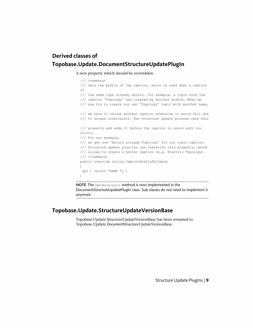
A new property which should be overridden:
/// <summary>
/// Gets the prefix of the caption, which is used when a caption
of
/// the same type already exists. For example, a topic with the
/// caption 'Topology' was created by another module. When we
/// now try to create our own 'Topology' topic with another name,
/// we have to choose another caption otherwise it would fail due
/// to unique constraints. The structure update process uses this
/// property and adds it before the caption to avoid such con
flicts.
/// For our example,
/// we get now 'Exists already Topology' for our topic caption.
/// Structure update plug-ins can overwrite this property, which
/// allows to create a better caption (e.g. Electric Topology).
/// </summary>
public override string CaptionPrefixFallback
{
get { return "DEMO "; }
}
NOTE The GetVersions() method is now implemented in theDocumentStructureUpdatePlugIn class. Sub classes do not need to implement itanymore.
Topobase.Update.StructureUpdateVersionBaseTopobase.Update.StructureUpdateVersionBase has been renamed toTopobase.Update.DocumentStructureUpdateVersionBase.
Structure Update PlugIns | 9
XML-Based Data Models
OverviewXML-based data models are defined in an XML file, which contains allnecessary information to create a data model in Autodesk Topobase. It alsocontains version steps to support updating of existing data models. The XMLfile is edited with the new Topobase Structure Editor application(Topobase.StructureEditor.exe) , which is part of Autodesk TopobaseAdministrator.
For more information about the Structure Editor, see the Topobase StructureEditor topic in Autodesk Topobase Administrator Help.
Advantages (over the old update method):
■ Partners and customers can create their own data models and enhance ourdata models (= data model extension) with the Structure Editor.
■ Simplest data models (and data model extensions) works with a .genx fileonly. No programming is required
Supported Features
■ Topics
■ Feature classes (including label feature classes)
■ Label definitions
■ Model feature class
■ Domain tables (including domain entries)
■ Views (only for feature classes)
■ Ordinary tables (not feature class nor domain table)
■ Attributes (of a feature class or a table)
■ Relations
■ Topologies
■ Area Topology
10 | Chapter 2 New and Changed API Content in Topobase 2011
■ Logical Topology
■ Utility models
■ Intersections
■ Indexes (Only special cases have to be specified)
■ Sequences
■ Rows of tables (basic data exchange support)
Unsupported Features
■ Feature rules
■ Workflows
■ Job Templates
■ Data Checker Definitions
■ Feature Search
■ Reference rows
■ (Everything else not specified here)
NOTE If a structure update requires creating, updating, or deleting an unsupportedfeature, the developer must use conventional structure update steps (for example,programmed in C#).
Important RulesDuring development, Autodesk found some rules that are extremely importantto follow. Otherwise, the process may fail:
■ All structure changes must be done in the .genx file.
■ All string resources must be stored in the .genx file.
■ The generated resource file must not be updated manually.
If an update cannot be done in the .genx file completely then a ‘before’ or‘after’ update event should be implemented (for example, rename a featureclass).
XML-Based Data Models | 11
Using conventional version updates are valid, however, the .genx file openedin the Structure Editor, must represent the data model 100% (not 99%).
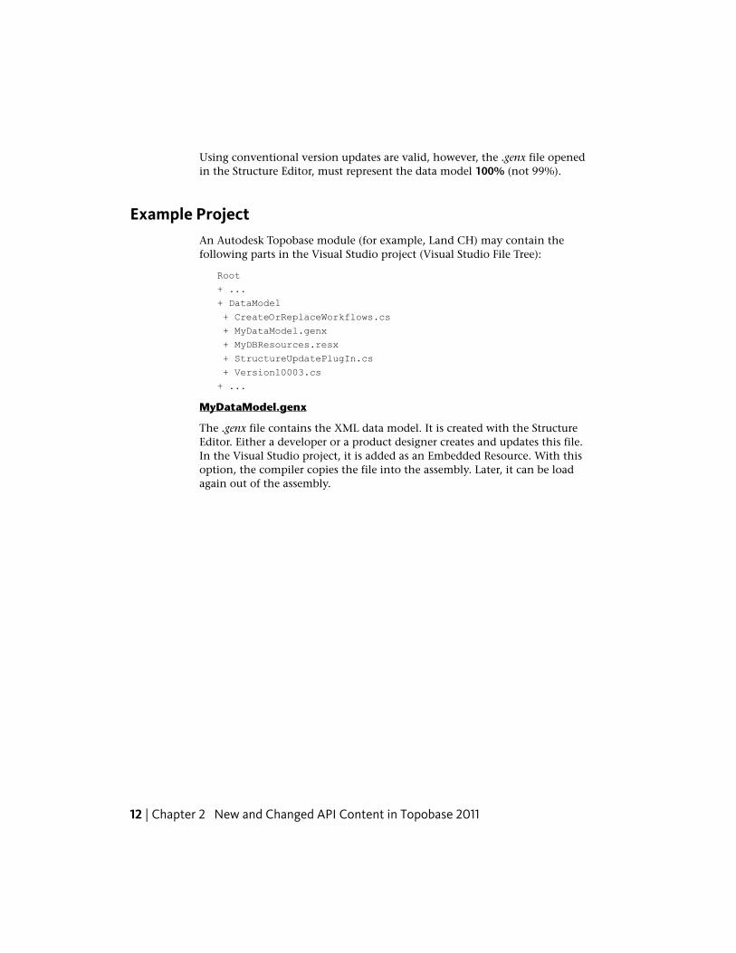
Example ProjectAn Autodesk Topobase module (for example, Land CH) may contain thefollowing parts in the Visual Studio project (Visual Studio File Tree):
Root
+ ...
+ DataModel
+ CreateOrReplaceWorkflows.cs
+ MyDataModel.genx
+ MyDBResources.resx
+ StructureUpdatePlugIn.cs
+ Version10003.cs
+ ...
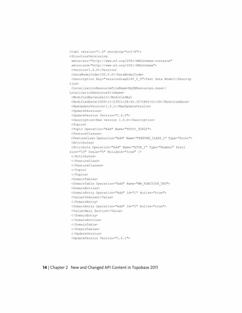
MyDataModel.genx
The .genx file contains the XML data model. It is created with the StructureEditor. Either a developer or a product designer creates and updates this file.In the Visual Studio project, it is added as an Embedded Resource. With thisoption, the compiler copies the file into the assembly. Later, it can be loadagain out of the assembly.
12 | Chapter 2 New and Changed API Content in Topobase 2011

Example XML:
XML-Based Data Models | 13
<?xml version="1.0" encoding="utf-8"?>
<StructureVersioning
xmlns:xsi="http://www.w3.org/2001/XMLSchema-instance"
xmlns:xsd="http://www.w3.org/2001/XMLSchema">
<Version>1.0.0</Version>
<DataModelCode>100.0.0</DataModelCode>
<Description Key="versionGraph100_0_0">Test Data Model</Descrip
tion>
<LocalizationResourceFileName>MyDBResources.resx</
LocalizationResourceFileName>
<ModifiedBy>weibelt</ModifiedBy>
<ModifiedDate>2009-11-23T15:08:40.3075805+01:00</ModifiedDate>
<MaxUpdateVersion>1.0.1</MaxUpdateVersion>
<UpdateVersions>
<UpdateVersion Version="1.0.0">
<Description>New version 1.0.0</Description>
<Topics>
<Topic Operation="Add" Name="TOPIC_92802">
<FeatureClasses>
<FeatureClass Operation="Add" Name="FEATURE_CLASS_1" Type="Point">
<Attributes>
<Attribute Operation="Add" Name="ATTR_1" Type="Number" Preci
sion="10" Scale="0" Nullable="true" />
</Attributes>
</FeatureClass>
</FeatureClasses>
</Topic>
</Topics>
<DomainTables>
<DomainTable Operation="Add" Name="WW_FUNCTION_TBD">
<DomainEntries>
<DomainEntry Operation="Add" Id="1" Active="true">
<Value>Unknown</Value>
</DomainEntry>
<DomainEntry Operation="Add" Id="2" Active="true">
<Value>Main Section</Value>
</DomainEntry>
</DomainEntries>
</DomainTable>
</DomainTables>
</UpdateVersion>
<UpdateVersion Version="1.0.1">
14 | Chapter 2 New and Changed API Content in Topobase 2011
<Description Key="updateVersion1_0_1">New version 1.0.1</Descrip
tion>
<Topics>
<Topic Operation="None" Name="TOPIC_92802">
<FeatureClasses>
<FeatureClass Operation="None" Name="FEATURE_CLASS_1"
Type="Point">
<Attributes>
<Attribute Operation="Update" Name="ATTR_1" Type="Number" Preci
sion="10" Scale="0" Nullable="false" />
<Attribute Operation="Add" Name="ID_TYPE" Type="Number" Preci
sion="10" Scale="0" Nullable="true" />
</Attributes>
</FeatureClass>
</FeatureClasses>
</Topic>
</Topics>
<DomainTables>
<DomainTable Operation="None" Name="WW_FUNCTION_TBD">
<DomainEntries>
<DomainEntry Operation="Add" Id="3" Active="true">
<Value>Street Water</Value>
</DomainEntry>
</DomainEntries>
</DomainTable>
</DomainTables>
</UpdateVersion>
</UpdateVersions>
</StructureVersioning>
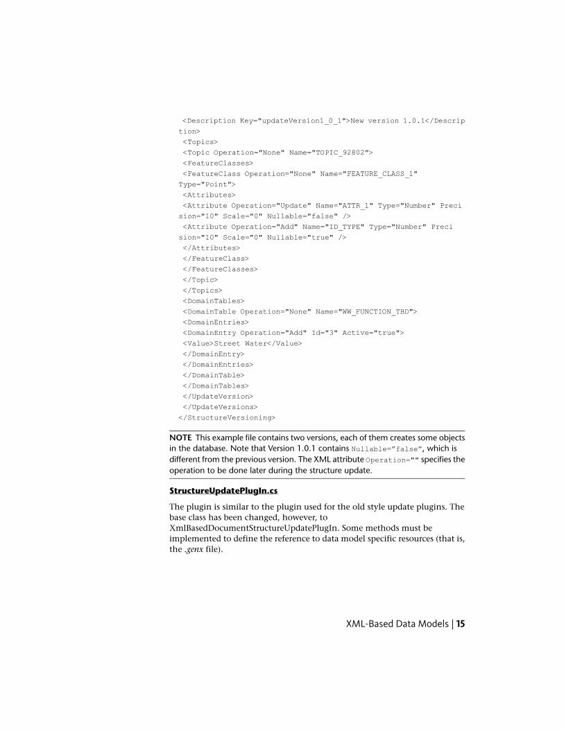
NOTE This example file contains two versions, each of them creates some objectsin the database. Note that Version 1.0.1 contains Nullable=”false”, which isdifferent from the previous version. The XML attribute Operation="" specifies theoperation to be done later during the structure update.
StructureUpdatePlugIn.cs
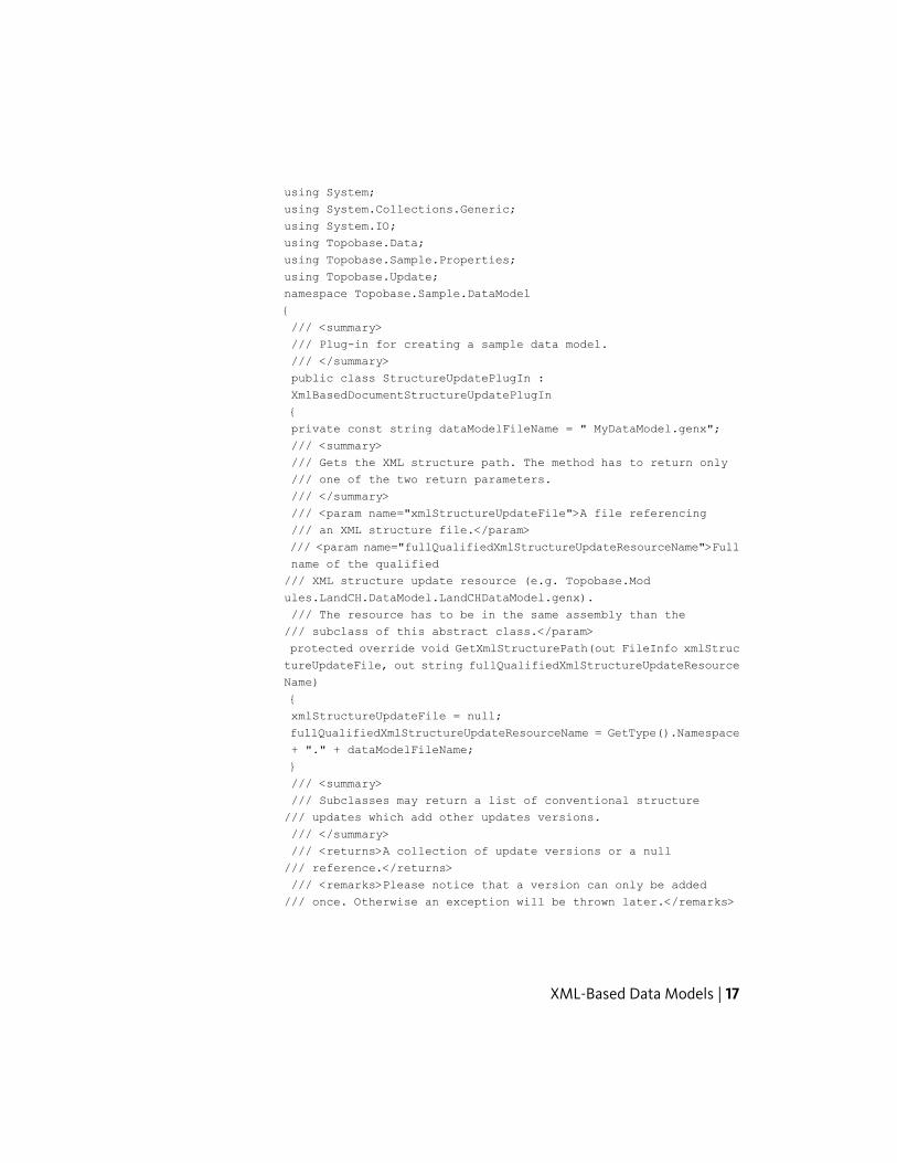
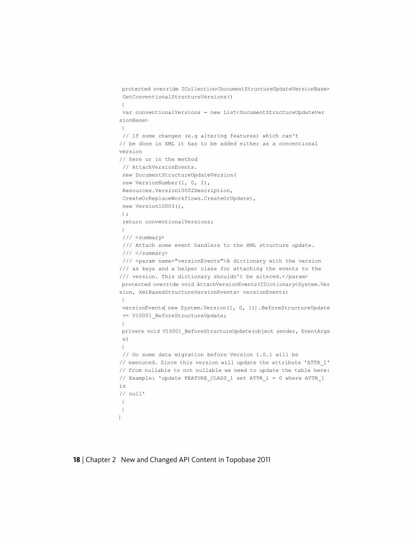
The plugin is similar to the plugin used for the old style update plugins. Thebase class has been changed, however, toXmlBasedDocumentStructureUpdatePlugIn. Some methods must beimplemented to define the reference to data model specific resources (that is,the .genx file).
XML-Based Data Models | 15

Example file:
16 | Chapter 2 New and Changed API Content in Topobase 2011
using System;
using System.Collections.Generic;
using System.IO;
using Topobase.Data;
using Topobase.Sample.Properties;
using Topobase.Update;
namespace Topobase.Sample.DataModel
{
/// <summary>
/// Plug-in for creating a sample data model.
/// </summary>
public class StructureUpdatePlugIn :
XmlBasedDocumentStructureUpdatePlugIn
{
private const string dataModelFileName = " MyDataModel.genx";
/// <summary>
/// Gets the XML structure path. The method has to return only
/// one of the two return parameters.
/// </summary>
/// <param name="xmlStructureUpdateFile">A file referencing
/// an XML structure file.</param>
/// <param name="fullQualifiedXmlStructureUpdateResourceName">Full
name of the qualified
/// XML structure update resource (e.g. Topobase.Mod
ules.LandCH.DataModel.LandCHDataModel.genx).
/// The resource has to be in the same assembly than the
/// subclass of this abstract class.</param>
protected override void GetXmlStructurePath(out FileInfo xmlStruc
tureUpdateFile, out string fullQualifiedXmlStructureUpdateResource
Name)
{
xmlStructureUpdateFile = null;
fullQualifiedXmlStructureUpdateResourceName = GetType().Namespace
+ "." + dataModelFileName;
}
/// <summary>
/// Subclasses may return a list of conventional structure
/// updates which add other updates versions.
/// </summary>
/// <returns>A collection of update versions or a null
/// reference.</returns>
/// <remarks>Please notice that a version can only be added
/// once. Otherwise an exception will be thrown later.</remarks>
XML-Based Data Models | 17
protected override ICollection<DocumentStructureUpdateVersionBase>
GetConventionalStructureVersions()
{
var conventionalVersions = new List<DocumentStructureUpdateVer
sionBase>
{
// If some changes (e.g altering features) which can't
// be done in XML it has to be added either as a conventional
version
// here or in the method
// AttachVersionEvents.
new DocumentStructureUpdateVersion(
new VersionNumber(1, 0, 2),
Resources.Version10002Description,
CreateOrReplaceWorkflows.CreateOrUpdate),
new Version10003(),
};
return conventionalVersions;
}
/// <summary>
/// Attach some event handlers to the XML structure update.
/// </summary>
/// <param name="versionEvents">A dictionary with the version
/// as keys and a helper class for attaching the events to the
/// version. This dictionary shouldn't be altered.</param>
protected override void AttachVersionEvents(IDictionary<System.Ver
sion, XmlBasedStructureVersionEvents> versionEvents)
{
versionEvents[new System.Version(1, 0, 1)].BeforeStructureUpdate
+= V10001_BeforeStructureUpdate;
}
private void V10001_BeforeStructureUpdate(object sender, EventArgs
e)
{
// Do some data migration before Version 1.0.1 will be
// executed. Since this version will update the attribute 'ATTR_1'
// from nullable to not nullable we need to update the table here:
// Example: 'update FEATURE_CLASS_1 set ATTR_1 = 0 where ATTR_1
is
// null'
}
}
}
18 | Chapter 2 New and Changed API Content in Topobase 2011
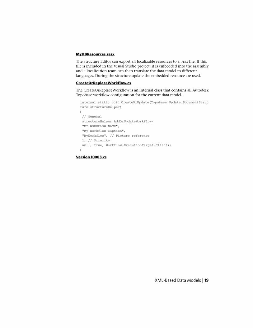
MyDBResources.resx
The Structure Editor can export all localizable resources to a .resx file. If thisfile is included in the Visual Studio project, it is embedded into the assemblyand a localization team can then translate the data model to differentlanguages. During the structure update the embedded resource are used.
CreateOrReplaceWorkflow.cs
The CreateOrReplaceWorkflow is an internal class that contains all AutodeskTopobase workflow configuration for the current data model.
internal static void CreateOrUpdate(Topobase.Update.DocumentStruc
ture structureHelper)
{
// General
structureHelper.AddOrUpdateWorkflow(
"MY_WORKFLOW_NAME",
"My Workflow Caption",
"MyWorkflow", // Picture reference
1, // Priority
null, true, Workflow.ExecutionTarget.Client);
}
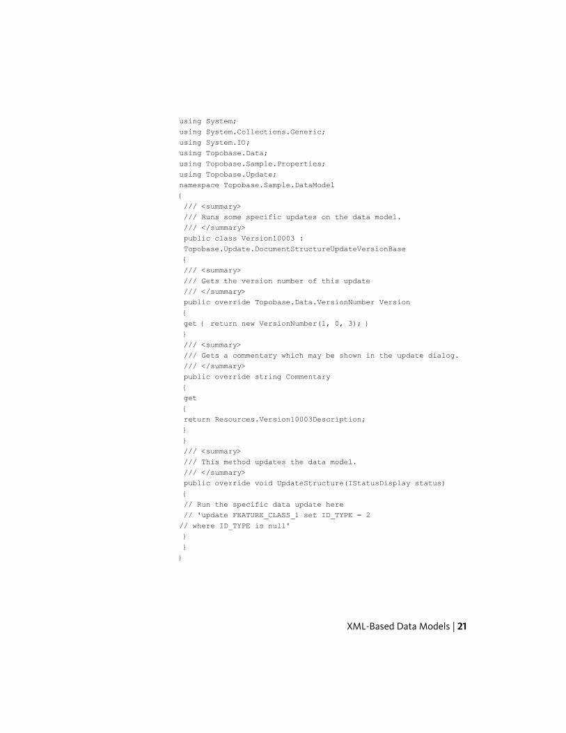
Version10003.cs
XML-Based Data Models | 19

Specifies a version step that cannott be done in the XML file. For example,updating the value of a specific feature attribute (for example, ID_TYPE: null--> Main Section).
20 | Chapter 2 New and Changed API Content in Topobase 2011
using System;
using System.Collections.Generic;
using System.IO;
using Topobase.Data;
using Topobase.Sample.Properties;
using Topobase.Update;
namespace Topobase.Sample.DataModel
{
/// <summary>
/// Runs some specific updates on the data model.
/// </summary>
public class Version10003 :
Topobase.Update.DocumentStructureUpdateVersionBase
{
/// <summary>
/// Gets the version number of this update
/// </summary>
public override Topobase.Data.VersionNumber Version
{
get { return new VersionNumber(1, 0, 3); }
}
/// <summary>
/// Gets a commentary which may be shown in the update dialog.
/// </summary>
public override string Commentary
{
get
{
return Resources.Version10003Description;
}
}
/// <summary>
/// This method updates the data model.
/// </summary>
public override void UpdateStructure(IStatusDisplay status)
{
// Run the specific data update here
// 'update FEATURE_CLASS_1 set ID_TYPE = 2
// where ID_TYPE is null'
}
}
}
XML-Based Data Models | 21
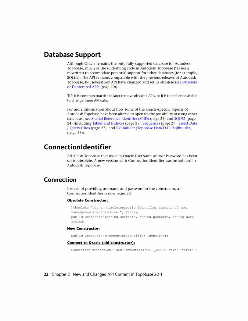
Database SupportAlthough Oracle remains the only fully supported database for AutodeskTopobase, much of the underlying code in Autodesk Topobase has beenre-written to accomodate potential support for other databases (for example,SQLite). The API remains compatible with the previous releases of AutodeskTopobase, but several key API have changed and set to obsolete (see Obsoleteor Deprecated APIs (page 40)).
TIP It is common practice to later remove obsolete APIs, so it is therefore advisableto change these API calls.
For more information about how some of the Oracle-specific aspects ofAutodesk Topobase have been altered to open up the possibility of using otherdatabases, see Spatial Reference Identifier (SRID) (page 23) and SQL92 (page24) (including Tables and Indexes (page 25), Sequences (page 27), Select Data/ Query Class (page 27), and ISqlBuilder (Topobase.Data.DAL.ISqlBuilder)(page 33)).
ConnectionIdentifierAll API in Topobase that used an Oracle UserName and/or Password has beenset to obsolete. A new version with ConnectionIdentifier was introduced inAutodesk Topobase.
ConnectionInstead of providing username and password in the constructor, aConnectionIdentifier is now required:
Obsolete Constructor:
[Obsolete("Use an OracleConnectionIdentifier instead of user
name/password/datasource.", false)]
public Connection(string username, string password, string data
source)
New Constructor:
public Connection(ConnectionIdentifier identifier)
Connect to Oracle (old constructor):
Connection connection = new Connection("TB11_LAND", "avs", "orcl");
22 | Chapter 2 New and Changed API Content in Topobase 2011

Connect to Oracle (new API):
ConnectionIdentifier.Oracle identifier = ConnectionIdentifier.Cre
ate<ConnectionIdentifier.Oracle>();
identifier.UserName = "TB11_LAND";
identifier.Password = "avs";
identifier.ServiceName = "orcl";
Connection cn = new Connection(identifier);
Topobase.Data.Sys.DocumentA document represents an Autodesk Topobase data schema that uses aSysConnection in order to manage the metadata table TB_DOCUMENT. TheTB_DOCUMENT was used to store the username and encrypted password toestablish a connection to Oracle. Because a document may not be in Oraclein a future release and different parameters are required to establish aconnection, the ConnectionIdentifier is stored in new tableTB_DOCUMENT_CONNECTION. The columns username and password arestill updated but this might change in the future. What changed is the use of“name”: Prior to Autodesk Topobase 2011, “name” and “username” areidentical. In Autodesk Topobase 2011, “name” is a mere description, or captionof the document.
[Obsolete("Use overloaded constructor with ConnectionIdentifier",
false)]
public Document(SysConnection connection, string name, string
username, string password)
public Document(SysConnection connection, string name, Connec
tionIdentifier connectionIdentifier)
Spatial Reference Identifier (SRID)An SRID (Spatial Reference IDentifier) is an integer value key into a tablecontaining spatial reference information. For Oracle Spatial, that table isMDSYS.CS_SRS. Together with other information, each table has a columncontaining a text string that describes a coordinate system. This string is oftenreferred to as the projection string. For Oracle, the column is called WKTEXT.
Oracle Spatial stores a large number of predefined projection strings in thetable MDSYS.CS_SRS. The primary key into this table is the Oracle SRID.
Other databases like SQLite don't feature any spatial support and thereforedon't have an SRID.
Topobase.Data.Sys.Document | 23
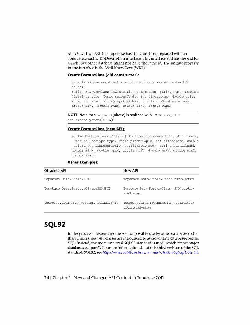
All API with an SRID in Topobase has therefore been replaced with anTopobase.Graphic.ICsDescription interface. This interface still has the srid forOracle, but other database might not have the same id. The unique propertyin the interface is the Well Know Text (WKT).
Create FeatureClass (old constructor):
[Obsolete("Use constructor with coordinate system instead.",
false)]
public FeatureClass(TBConnection connection, string name, Feature
ClassType type, Topic parentTopic, int dimensions, double toler
ance, int srid, string spatialMask, double minX, double maxX,
double minY, double maxY, double minZ, double maxZ)
NOTE Note that int srid (above) is replaced with iCsDescriptioncoordinateSystem (below).
Create FeatureClass (new API):
public FeatureClass([NotNull] TBConnection connection, string name,
FeatureClassType type, Topic parentTopic, int dimensions, double
tolerance, ICsDescription coordinateSystem, string spatialMask,
double minX, double maxX, double minY, double maxY, double minZ,
double maxZ)
Other Examples:
New APIObsolete API
Topobase.Data.Table.CoordinateSystemTopobase.Data.Table.SRID
Topobase.Data.FeatureClass. SDOCoordin-
ateSystem
Topobase.Data.FeatureClass.SDOSRID
Topobase.Data.TBConnection. DefaultCo-
ordinateSystem
Topobase.Data.TBConnection. DefaultSRID
SQL92In the process of extending the API for possible use by other databases (otherthan Oracle), new API classes are introduced to avoid writing database-specificSQL. Instead, the more universal SQL92 standard is used, which “most majordatabases support”. For more information about this third revision of the SQLstandard, SQL92, see http://www.contrib.andrew.cmu.edu/~shadow/sql/sql1992.txt.
24 | Chapter 2 New and Changed API Content in Topobase 2011
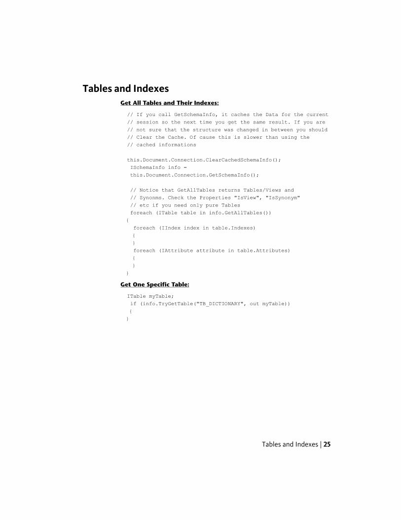
Tables and IndexesGet All Tables and Their Indexes:
// If you call GetSchemaInfo, it caches the Data for the current
// session so the next time you get the same result. If you are
// not sure that the structure was changed in between you should
// Clear the Cache. Of cause this is slower than using the
// cached informations
this.Document.Connection.ClearCachedSchemaInfo();
ISchemaInfo info =
this.Document.Connection.GetSchemaInfo();
// Notice that GetAllTables returns Tables/Views and
// Synonms. Check the Properties "IsView", "IsSynonym"
// etc if you need only pure Tables
foreach (ITable table in info.GetAllTables())
{
foreach (IIndex index in table.Indexes)
{
}
foreach (IAttribute attribute in table.Attributes)
{
}
}
Get One Specific Table:
ITable myTable;
if (info.TryGetTable("TB_DICTIONARY", out myTable))
{
}
Tables and Indexes | 25
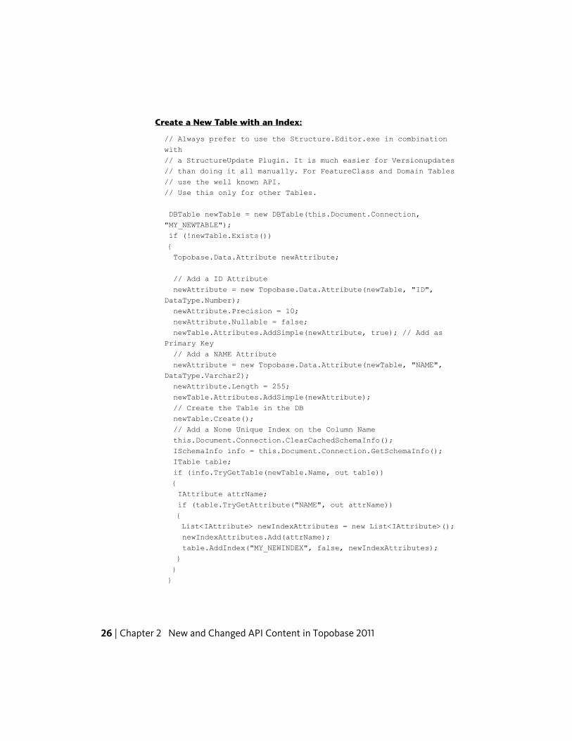
Create a New Table with an Index:
// Always prefer to use the Structure.Editor.exe in combination
with
// a StructureUpdate Plugin. It is much easier for Versionupdates
// than doing it all manually. For FeatureClass and Domain Tables
// use the well known API.
// Use this only for other Tables.
DBTable newTable = new DBTable(this.Document.Connection,
"MY_NEWTABLE");
if (!newTable.Exists())
{
Topobase.Data.Attribute newAttribute;
// Add a ID Attribute
newAttribute = new Topobase.Data.Attribute(newTable, "ID",
DataType.Number);
newAttribute.Precision = 10;
newAttribute.Nullable = false;
newTable.Attributes.AddSimple(newAttribute, true); // Add as
Primary Key
// Add a NAME Attribute
newAttribute = new Topobase.Data.Attribute(newTable, "NAME",
DataType.Varchar2);
newAttribute.Length = 255;
newTable.Attributes.AddSimple(newAttribute);
// Create the Table in the DB
newTable.Create();
// Add a None Unique Index on the Column Name
this.Document.Connection.ClearCachedSchemaInfo();
ISchemaInfo info = this.Document.Connection.GetSchemaInfo();
ITable table;
if (info.TryGetTable(newTable.Name, out table))
{
IAttribute attrName;
if (table.TryGetAttribute("NAME", out attrName))
{
List<IAttribute> newIndexAttributes = new List<IAttribute>();
newIndexAttributes.Add(attrName);
table.AddIndex("MY_NEWINDEX", false, newIndexAttributes);
}
}
}
26 | Chapter 2 New and Changed API Content in Topobase 2011
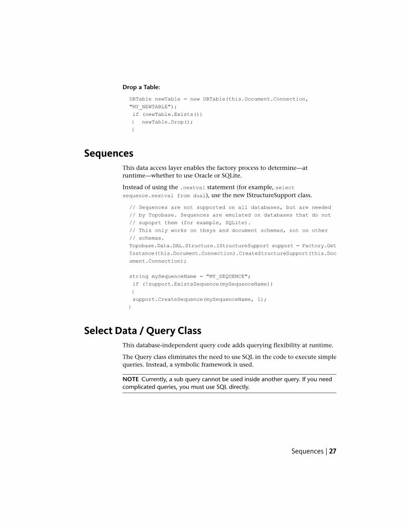
Drop a Table:
DBTable newTable = new DBTable(this.Document.Connection,
"MY_NEWTABLE");
if (newTable.Exists())
{ newTable.Drop();
}
SequencesThis data access layer enables the factory process to determine—atruntime—whether to use Oracle or SQLite.
Instead of using the .nextval statement (for example, selectsequence.nextval from dual), use the new IStructureSupport class.
// Sequences are not supported on all databases, but are needed
// by Topobase. Sequences are emulated on databases that do not
// supoprt them (for example, SQLite).
// This only works on tbsys and document schemas, not on other
// schemas.
Topobase.Data.DAL.Structure.IStructureSupport support = Factory.Get
Instance(this.Document.Connection).CreateStructureSupport(this.Doc
ument.Connection);
string mySequenceName = "MY_SEQUENCE";
if (!support.ExistsSequence(mySequenceName))
{
support.CreateSequence(mySequenceName, 1);
}
Select Data / Query ClassThis database-independent query code adds querying flexibility at runtime.
The Query class eliminates the need to use SQL in the code to execute simplequeries. Instead, a symbolic framework is used.
NOTE Currently, a sub query cannot be used inside another query. If you needcomplicated queries, you must use SQL directly.
Sequences | 27
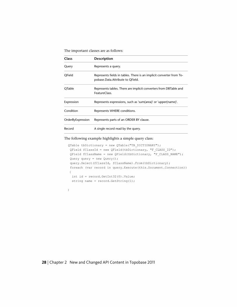
The important classes are as follows:
DescriptionClass
Represents a query.Query
Represents fields in tables. There is an implicit converter from To-pobase.Data.Attribute to QField.
QField
Represents tables. There are implicit converters from DBTable andFeatureClass.
QTable
Represents expressions, such as 'sum(area)' or 'upper(name)'.Expression
Represents WHERE conditions.Condition
Represents parts of an ORDER BY clause.OrderByExpression
A single record read by the query.Record
The following example highlights a simple query class:
QTable tbDictionary = new QTable("TB_DICTIONARY");
QField fClassId = new QField(tbDictionary, "F_CLASS_ID");
QField fClassName = new QField(tbDictionary, "F_CLASS_NAME");
Query query = new Query();
query.Select(fClassId, fClassName).From(tbDictionary);
foreach (var record in query.Execute(this.Document.Connection))
{
int id = record.GetInt32(0).Value;
string name = record.GetString(1);
}
28 | Chapter 2 New and Changed API Content in Topobase 2011
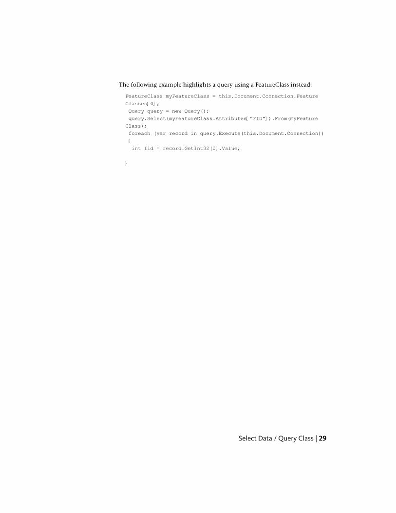
The following example highlights a query using a FeatureClass instead:
FeatureClass myFeatureClass = this.Document.Connection.Feature
Classes[0];
Query query = new Query();
query.Select(myFeatureClass.Attributes["FID"]).From(myFeature
Class);
foreach (var record in query.Execute(this.Document.Connection))
{
int fid = record.GetInt32(0).Value;
}
Select Data / Query Class | 29
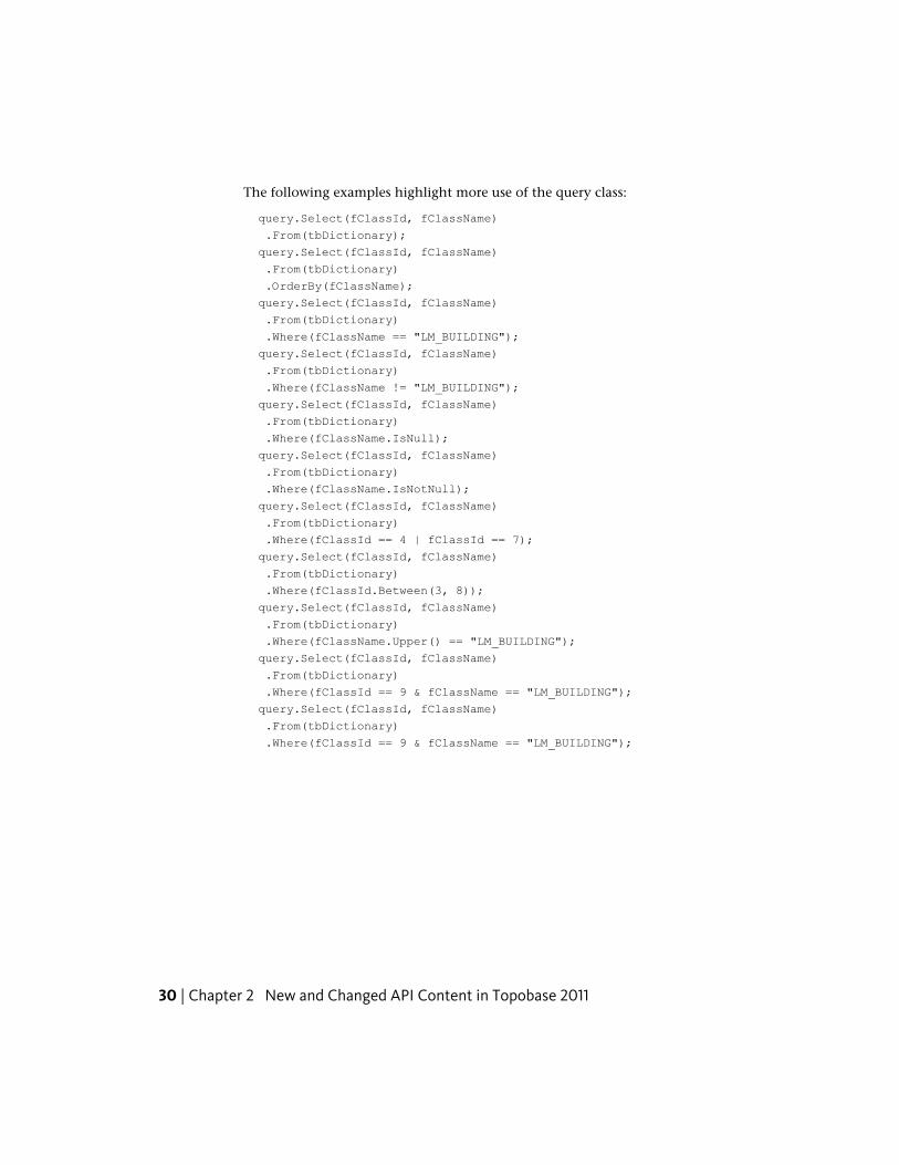
The following examples highlight more use of the query class:
query.Select(fClassId, fClassName)
.From(tbDictionary);
query.Select(fClassId, fClassName)
.From(tbDictionary)
.OrderBy(fClassName);
query.Select(fClassId, fClassName)
.From(tbDictionary)
.Where(fClassName == "LM_BUILDING");
query.Select(fClassId, fClassName)
.From(tbDictionary)
.Where(fClassName != "LM_BUILDING");
query.Select(fClassId, fClassName)
.From(tbDictionary)
.Where(fClassName.IsNull);
query.Select(fClassId, fClassName)
.From(tbDictionary)
.Where(fClassName.IsNotNull);
query.Select(fClassId, fClassName)
.From(tbDictionary)
.Where(fClassId == 4 | fClassId == 7);
query.Select(fClassId, fClassName)
.From(tbDictionary)
.Where(fClassId.Between(3, 8));
query.Select(fClassId, fClassName)
.From(tbDictionary)
.Where(fClassName.Upper() == "LM_BUILDING");
query.Select(fClassId, fClassName)
.From(tbDictionary)
.Where(fClassId == 9 & fClassName == "LM_BUILDING");
query.Select(fClassId, fClassName)
.From(tbDictionary)
.Where(fClassId == 9 & fClassName == "LM_BUILDING");
30 | Chapter 2 New and Changed API Content in Topobase 2011

The following example enumerates over the feature IDs of all point and linefeatures that interact spatially; it is also shown in Sample 128 - DatabaseIndependant:
Select Data / Query Class | 31
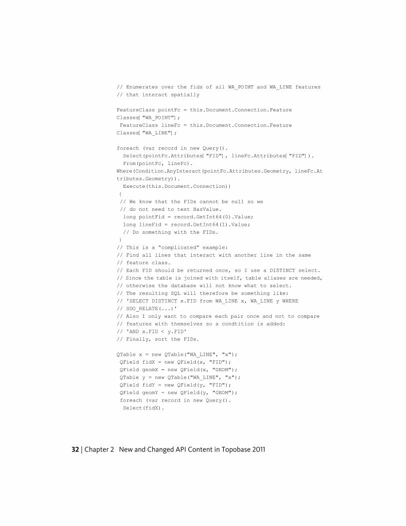
// Enumerates over the fids of all WA_POINT and WA_LINE features
// that interact spatially
FeatureClass pointFc = this.Document.Connection.Feature
Classes["WA_POINT"];
FeatureClass lineFc = this.Document.Connection.Feature
Classes["WA_LINE"];
foreach (var record in new Query().
Select(pointFc.Attributes["FID"], lineFc.Attributes["FID"]).
From(pointFc, lineFc).
Where(Condition.AnyInteract(pointFc.Attributes.Geometry, lineFc.At
tributes.Geometry)).
Execute(this.Document.Connection))
{
// We know that the FIDs cannot be null so we
// do not need to test HasValue.
long pointFid = record.GetInt64(0).Value;
long lineFid = record.GetInt64(1).Value;
// Do something with the FIDs.
}
// This is a “complicated” example:
// Find all lines that interact with another line in the same
// feature class.
// Each FID should be returned once, so I use a DISTINCT select.
// Since the table is joined with itself, table aliases are needed,
// otherwise the database will not know what to select.
// The resulting SQL will therefore be something like:
// 'SELECT DISTINCT x.FID from WA_LINE x, WA_LINE y WHERE
// SDO_RELATE(...)'
// Also I only want to compare each pair once and not to compare
// features with themselves so a condtition is added:
// 'AND x.FID < y.FID'
// Finally, sort the FIDs.
QTable x = new QTable("WA_LINE", "x");
QField fidX = new QField(x, "FID");
QField geomX = new QField(x, "GEOM");
QTable y = new QTable("WA_LINE", "x");
QField fidY = new QField(y, "FID");
QField geomY = new QField(y, "GEOM");
foreach (var record in new Query().
Select(fidX).
32 | Chapter 2 New and Changed API Content in Topobase 2011
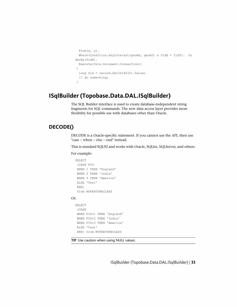
From(x, y).
Where(Condition.AnyInteract(geomX, geomY) & fidX < fidY). Or
derBy(fidX).
Execute(this.Document.Connection))
{
long fid = record.GetInt64(0).Value;
// do something;
}
ISqlBuilder (Topobase.Data.DAL.ISqlBuilder)The SQL Builder interface is used to create database-independent stringfragments for SQL commands. The new data access layer provides moreflexibilty for possible use with databases other than Oracle.
DECODE()DECODE is a Oracle-specific statement. If you cannot use the API, then use"case ~ when ~ else ~ end" instead.
This is standard SQL92 and works with Oracle, SQLite, SQLServer, and others.
For example:
SELECT
(CASE FID
WHEN 1 THEN 'England'
WHEN 2 THEN 'India'
WHEN 3 THEN 'America'
ELSE 'Test'
END)
from MYFEATURECLASS
Or:
SELECT
(CASE
WHEN FID=1 THEN 'England'
WHEN FID=2 THEN 'India'
WHEN FID=3 THEN 'America'
ELSE 'Test'
END) from MYFEATURECLASS
TIP Use caution when using NULL values.
ISqlBuilder (Topobase.Data.DAL.ISqlBuilder) | 33
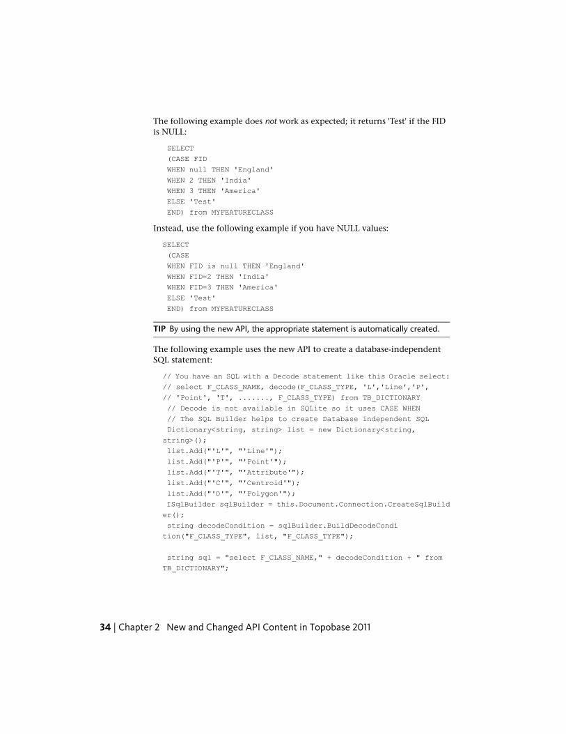
The following example does not work as expected; it returns 'Test' if the FIDis NULL:
SELECT
(CASE FID
WHEN null THEN 'England'
WHEN 2 THEN 'India'
WHEN 3 THEN 'America'
ELSE 'Test'
END) from MYFEATURECLASS
Instead, use the following example if you have NULL values:
SELECT
(CASE
WHEN FID is null THEN 'England'
WHEN FID=2 THEN 'India'
WHEN FID=3 THEN 'America'
ELSE 'Test'
END) from MYFEATURECLASS
TIP By using the new API, the appropriate statement is automatically created.
The following example uses the new API to create a database-independentSQL statement:
// You have an SQL with a Decode statement like this Oracle select:
// select F_CLASS_NAME, decode(F_CLASS_TYPE, 'L','Line','P',
// 'Point', 'T', ......., F_CLASS_TYPE) from TB_DICTIONARY
// Decode is not available in SQLite so it uses CASE WHEN
// The SQL Builder helps to create Database independent SQL
Dictionary<string, string> list = new Dictionary<string,
string>();
list.Add("'L'", "'Line'");
list.Add("'P'", "'Point'");
list.Add("'T'", "'Attribute'");
list.Add("'C'", "'Centroid'");
list.Add("'O'", "'Polygon'");
ISqlBuilder sqlBuilder = this.Document.Connection.CreateSqlBuild
er();
string decodeCondition = sqlBuilder.BuildDecodeCondi
tion("F_CLASS_TYPE", list, "F_CLASS_TYPE");
string sql = "select F_CLASS_NAME," + decodeCondition + " from
TB_DICTIONARY";
34 | Chapter 2 New and Changed API Content in Topobase 2011
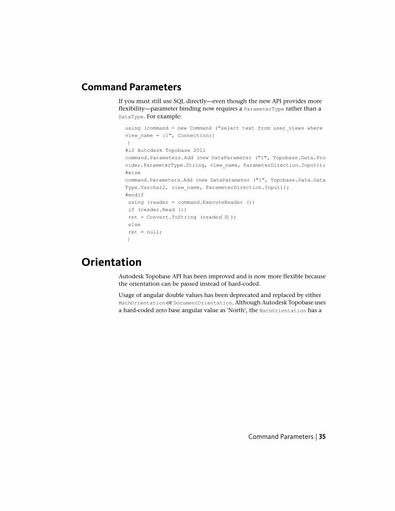
Command ParametersIf you must still use SQL directly—even though the new API provides moreflexibility—parameter binding now requires a ParameterType rather than aDataType. For example:
using (command = new Command ("select text from user_views where
view_name = :1", Connection))
{
#if Autodesk Topobase 2011
command.Parameters.Add (new DataParameter ("1", Topobase.Data.Pro
vider.ParameterType.String, view_name, ParameterDirection.Input));
#else
command.Parameters.Add (new DataParameter ("1", Topobase.Data.Data
Type.Varchar2, view_name, ParameterDirection.Input));
#endif
using (reader = command.ExecuteReader ())
if (reader.Read ())
ret = Convert.ToString (reader[0]);
else
ret = null;
}
OrientationAutodesk Topobase API has been improved and is now more flexible becausethe orientation can be passed instead of hard-coded.
Usage of angular double values has been deprecated and replaced by eitherMathOrientation or DocumentOrientation. Although Autodesk Topobase usesa hard-coded zero base angular value as 'North', the MathOrientation has a
Command Parameters | 35
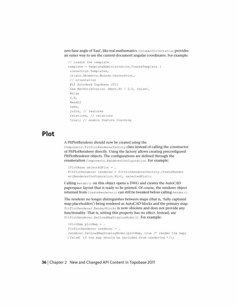
zero base angle of 'East', like real mathematics. DocumentOrientation providesan easier way to use the current document angular coordinates. For example:
// create the template
template = TemplateAdministration.CreateTemplate (
connection.Templates,
origin.Geometry.Bounds.CenterPoint,
// orientation
#if Autodesk Topobase 2011
new MathOrientation (Math.PI / 2.0, false),
#else
0.0,
#endif
name,
infos, // features
relations, // relations
true); // enable feature tracking
PlotA PltPlotRenderer should now be created using theComponents.PltPlotRendererFactory class instead of calling the constructorof PltPlotRenderer directly. Using the factory allows creating preconfiguredPltPlotRenderer objects. The configurations are defined through theenumeration Components.RendererConfiguration. For example:
IPlotBase selectedPlot = …
PltPlotRenderer renderer = PltPlotRendererFactory.CreateRender
er(RendererConfiguration.Plot, selectedPlot);
Calling Render() on this object opens a DWG and creates the AutoCADpaperspace layout that is ready to be printed. Of course, the renderer objectreturned from CreateRenderer() can still be tweaked before calling Render().
The renderer no longer distinguishes between maps (that is, ‘fully capturedmap placeholders’) being rendered as AutoCAD blocks and the primary map.PltPlotRenderer.RenderBlocks is now obsolete and does not provide anyfunctionality. That is, setting this property has no effect. Instead, usePltPlotRenderer.SetLoadMapDisplayModel(). For example:
IPlotMap plotMap = …
PltPlotRenderer renderer = …
renderer.SetLoadMapDisplayModel(plotMap, true /* render the map;
[false] if the map should be excluded from rendering */);
36 | Chapter 2 New and Changed API Content in Topobase 2011
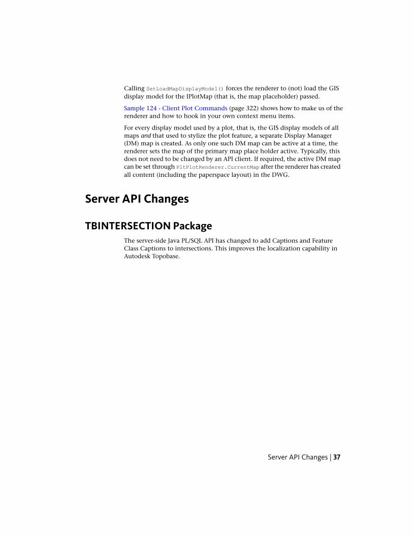
Calling SetLoadMapDisplayModel() forces the renderer to (not) load the GISdisplay model for the IPlotMap (that is, the map placeholder) passed.
Sample 124 - Client Plot Commands (page 322) shows how to make us of therenderer and how to hook in your own context menu items.
For every display model used by a plot, that is, the GIS display models of allmaps and that used to stylize the plot feature, a separate Display Manager(DM) map is created. As only one such DM map can be active at a time, therenderer sets the map of the primary map place holder active. Typically, thisdoes not need to be changed by an API client. If required, the active DM mapcan be set through PltPlotRenderer.CurrentMap after the renderer has createdall content (including the paperspace layout) in the DWG.
Server API Changes
TBINTERSECTION PackageThe server-side Java PL/SQL API has changed to add Captions and FeatureClass Captions to intersections. This improves the localization capability inAutodesk Topobase.
Server API Changes | 37
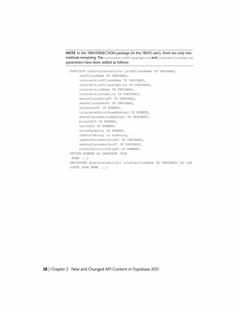
NOTE In the TBINTERSECTION package (in the TBSYS user), there are only twomethods remaining. The intersectionFClassCaption and intersectionCaptionparameters have been added as follows:
FUNCTION createIntersection( primFClassName IN VARCHAR2,
secFClassName IN VARCHAR2,
intersectionFClassName IN VARCHAR2,
intersectionFClassCaption IN VARCHAR2,
intersectionName IN VARCHAR2,
intersectionCaption IN VARCHAR2,
whereClausePrimFC IN VARCHAR2,
whereClauseSecFC IN VARCHAR2,
adjustSecFC IN NUMBER,
toleranceAdjustAreaNominal IN NUMBER,
whereClauseExcludeAdjust IN VARCHAR2,
primJobID IN NUMBER,
secJobID IN NUMBER,
storeGeometry IN NUMBER,
JobStateArray in numArray,
updateStatementPrimFC IN VARCHAR2,
updateStatementSecFC IN VARCHAR2,
bufferSelectionPrimFC IN NUMBER)
RETURN NUMBER AS LANGUAGE JAVA
NAME ...;
PROCEDURE dropIntersection( intersectionName IN VARCHAR2) AS LAN
GUAGE JAVA NAME ...;
38 | Chapter 2 New and Changed API Content in Topobase 2011
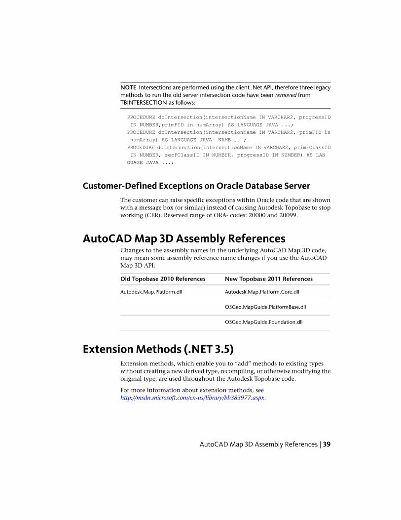
NOTE Intersections are performed using the client .Net API, therefore three legacymethods to run the old server intersection code have been removed fromTBINTERSECTION as follows:
PROCEDURE doIntersection(intersectionName IN VARCHAR2, progressID
IN NUMBER,primFID in numArray) AS LANGUAGE JAVA ...;
PROCEDURE doIntersection(intersectionName IN VARCHAR2, primFID in
numArray) AS LANGUAGE JAVA NAME ...;
PROCEDURE doIntersection(intersectionName IN VARCHAR2, primFClassID
IN NUMBER, secFClassID IN NUMBER, progressID IN NUMBER) AS LAN
GUAGE JAVA ...;
Customer-Defined Exceptions on Oracle Database ServerThe customer can raise specific exceptions within Oracle code that are shownwith a message box (or similar) instead of causing Autodesk Topobase to stopworking (CER). Reserved range of ORA- codes: 20000 and 20099.
AutoCAD Map 3D Assembly ReferencesChanges to the assembly names in the underlying AutoCAD Map 3D code,may mean some assembly reference name changes if you use the AutoCADMap 3D API:
New Topobase 2011 ReferencesOld Topobase 2010 References
Autodesk.Map.Platform.Core.dllAutodesk.Map.Platform.dll
OSGeo.MapGuide.PlatformBase.dll
OSGeo.MapGuide.Foundation.dll
Extension Methods (.NET 3.5)Extension methods, which enable you to “add” methods to existing typeswithout creating a new derived type, recompiling, or otherwise modifying theoriginal type, are used throughout the Autodesk Topobase code.
For more information about extension methods, seehttp://msdn.microsoft.com/en-us/library/bb383977.aspx.
AutoCAD Map 3D Assembly References | 39
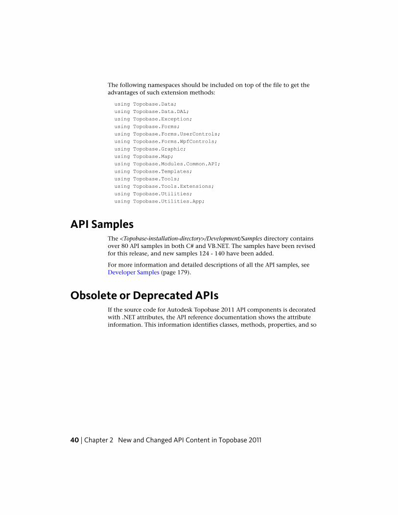
The following namespaces should be included on top of the file to get theadvantages of such extension methods:
using Topobase.Data;
using Topobase.Data.DAL;
using Topobase.Exception;
using Topobase.Forms;
using Topobase.Forms.UserControls;
using Topobase.Forms.WpfControls;
using Topobase.Graphic;
using Topobase.Map;
using Topobase.Modules.Common.API;
using Topobase.Templates;
using Topobase.Tools;
using Topobase.Tools.Extensions;
using Topobase.Utilities;
using Topobase.Utilities.App;
API SamplesThe <Topobase-installation-directory>/Development/Samples directory containsover 80 API samples in both C# and VB.NET. The samples have been revisedfor this release, and new samples 124 - 140 have been added.
For more information and detailed descriptions of all the API samples, seeDeveloper Samples (page 179).
Obsolete or Deprecated APIsIf the source code for Autodesk Topobase 2011 API components is decoratedwith .NET attributes, the API reference documentation shows the attributeinformation. This information identifies classes, methods, properties, and so
40 | Chapter 2 New and Changed API Content in Topobase 2011
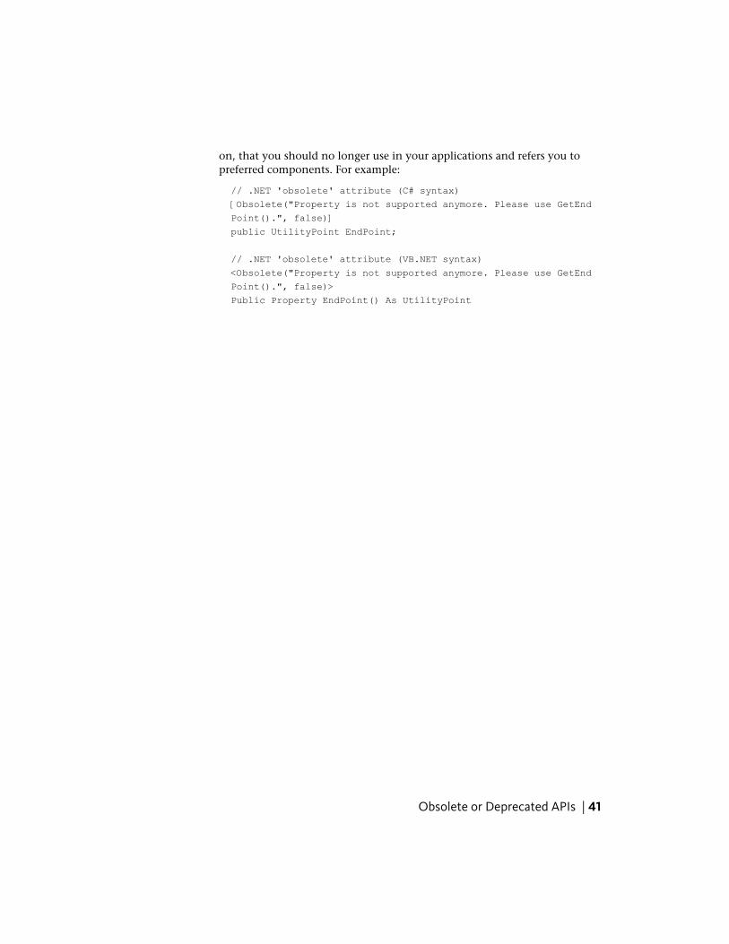
on, that you should no longer use in your applications and refers you topreferred components. For example:
// .NET 'obsolete' attribute (C# syntax)
[Obsolete("Property is not supported anymore. Please use GetEnd
Point().", false)]
public UtilityPoint EndPoint;
// .NET 'obsolete' attribute (VB.NET syntax)
<Obsolete("Property is not supported anymore. Please use GetEnd
Point().", false)>
Public Property EndPoint() As UtilityPoint
Obsolete or Deprecated APIs | 41

42
API Overview
DatabaseThis section covers basic database operations that are required for using the restof the Autodesk Topobase API.
Connecting to the DatabaseTo connect to the Oracle© database, initialize a new instance of the TBConnectionclass via its constructor and invoke its Open() method to open the connection.After successfully opening the connection, you can then proceed to carry outother tasks, such as creating feature classes and features. After completing allrequired tasks, close the connection by calling TBConnection.Close().
NOTE The connection should also be disposed of when it is no longer used.
3
43
The following code snippet shows the procedure for connecting to AutodeskTopobase:
using (Topobase.Data.TBConnection myConnection =
new Topobase.Data.TBConnection(
Properties.Settings.Default.Oracle_User,
Properties.Settings.Default.Oracle_Password,
this.Application.Connection.DataSource,
true,
this.Application.Connection))
{
// Open the connection to the database.
// If the DB has no database structure it is created now
myConnection.ShowForms = true;
myConnection.Open();
// Display the connection to the user.
string state = myConnection.State.ToString();
MessageBox.Show("Connection state:" + state);
// Close connection.
myConnection.Close();
}
Creating a New Database UserTo create a new database user, use the TBConnection.CreateTopobaseUser()method. This method takes as one of its parameters a Connection object thatcorresponds to the current user name and password.
44 | Chapter 3 API Overview

The following code snippet shows how to open a connection and create adatabase user:
Creating a New Database User | 45
// Create a new empty Oracle user.
string userName = Properties.Settings.Default.Oracle_User;
if (!this.Application.Connection.ExistsUser(userName))
{
// Project settings store the new database and password.
using (Topobase.Data.TBConnection myConnection =
new Topobase.Data.TBConnection(
Properties.Settings.Default.Oracle_User,
Properties.Settings.Default.Oracle_Password,
this.Application.Connection.DataSource,
true,
this.Application.Connection))
{
try
{
myConnection.CreateTopobaseUser(
this.Application.Connection,
"USERS",
"TEMP",
"USERS");
}
catch (Topobase.Exception.TBException ex)
{
if (ex.Caller == Topobase.Exception.TBExceptionCaller.TB3Server)
{
MessageBox.Show("Unable to create user:"
+ Environment.NewLine + ex.Message);
}
else
{
throw;
}
}
finally
{
myConnection.Close();
}
}
}
else
{
MessageBox.Show("User already exists.");
}
46 | Chapter 3 API Overview
Feature Classes
About Feature ClassesA feature class represents a type of Autodesk Topobase object, and correspondsto a single table within the database. For example, the concept of “parcel” isa single feature class. The list of all feature classes within a database is containedwithin the TBConnection object’s FeatureClasses property. To get a referenceto an existing feature class, you can specify the feature id or string name asthe index to the collection:
// Get a reference to the feature class named "MyPoint".
Topobase.Data.FeatureClass MyPointFeatureClass;
MyPointFeatureClass = myConnection.FeatureClasses["MyPoint"];
TopicsTopics are used to organize feature classes. A topic is a collection of featureclass tables that have some relationship meaningful to the user. For example,all feature classes related to pipes can be placed within a single topic named“Pipes”. Topics do not imply any table relationships between the feature classescontained within them. Topics may have subtopics as well. The collection ofall topics within a database is contained within the TBConnection object’sTopics property.
Topics are created by using the collection’s Add() method. To create subtopics,you can either use the overridden Add() method that takes the parent topicid as a parameter, or you can directly add topics to the parent topic’sChildTopic property.
Topobase.Data.Topic MyTopic;
MyTopic = myConnection.Topics.Add("MyTopic", "Caption");
// Add a subtopic.
Topobase.Data.Topic SubTopic;
SubTopic = MyTopic.ChildTopics.Add("SubTopic", "Caption");
Feature Classes | 47
Creating Feature ClassesTo create a new feature class, use the FeatureClass constructor to create anew object and then call the feature class object’s Create() method to addthe feature class to the database.
// Add a point-style feature class to the topic MyTopic.
Topobase.Data.FeatureClass MyPointFeatureClass;
// Do not create if it already exists.
if (!myConnection.FeatureClasses.Contains("MyPoint"))
{
// Create the feature class object.
MyPointFeatureClass = new Topobase.Data.FeatureClass(
myConnection,
"MyPoint",
"My point caption",
Topobase.Data.FeatureClassType.Point);
MyTopic);
// Add the feature class to the database and add references
// of the object to the specified topic and other locations.
MyPointFeatureClass.Create();
}
You can hierarchically organize feature classes by making one feature class achild of another feature class. To create a child feature class, use one of theconstructor overrides where you specify the parent feature class id as one ofthe parameters. The following code sample creates a new feature class, whichis a child of the previously created MyPointFeatureClass feature class:
Topobase.Data.FeatureClass ChildFeatureClass;
ChildFeatureClass = new Topobase.Data.FeatureClass(
myConnection,
"MyPoint",
"My point caption",
Topobase.Data.FeatureClassType.Point);
MyTopic,
MyPointFeatureClass.ID);
ChildFeatureClass.Create();
48 | Chapter 3 API Overview
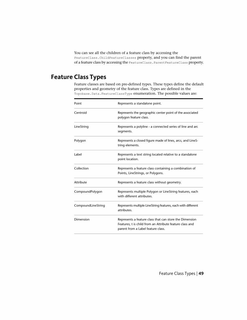
You can see all the children of a feature class by accessing theFeatureClass.ChildFeatureClasses property, and you can find the parentof a feature class by accessing the FeatureClass.ParentFeatureClass property.
Feature Class TypesFeature classes are based on pre-defined types. These types define the defaultproperties and geometry of the feature class. Types are defined in theTopobase.Data.FeatureClassType enumeration. The possible values are:
Represents a standalone point.Point
Represents the geographic center point of the associatedpolygon feature class.
Centroid
Represents a polyline - a connected series of line and arcsegments.
LineString
Represents a closed figure made of lines, arcs, and LineS-tring elements.
Polygon
Represents a text string located relative to a standalonepoint location.
Label
Represents a feature class containing a combination ofPoints, LineStrings, or Polygons.
Collection
Represents a feature class without geometry.Attribute
Represents multiple Polygon or LineString features, eachwith different attributes.
CompoundPolygon
Represents multiple LineString features, each with differentattributes.
CompoundLineString
Represents a feature class that can store the DimensionFeatures; t is child from an Attribute feature class andparent from a Label feature class.
Dimension
Feature Class Types | 49
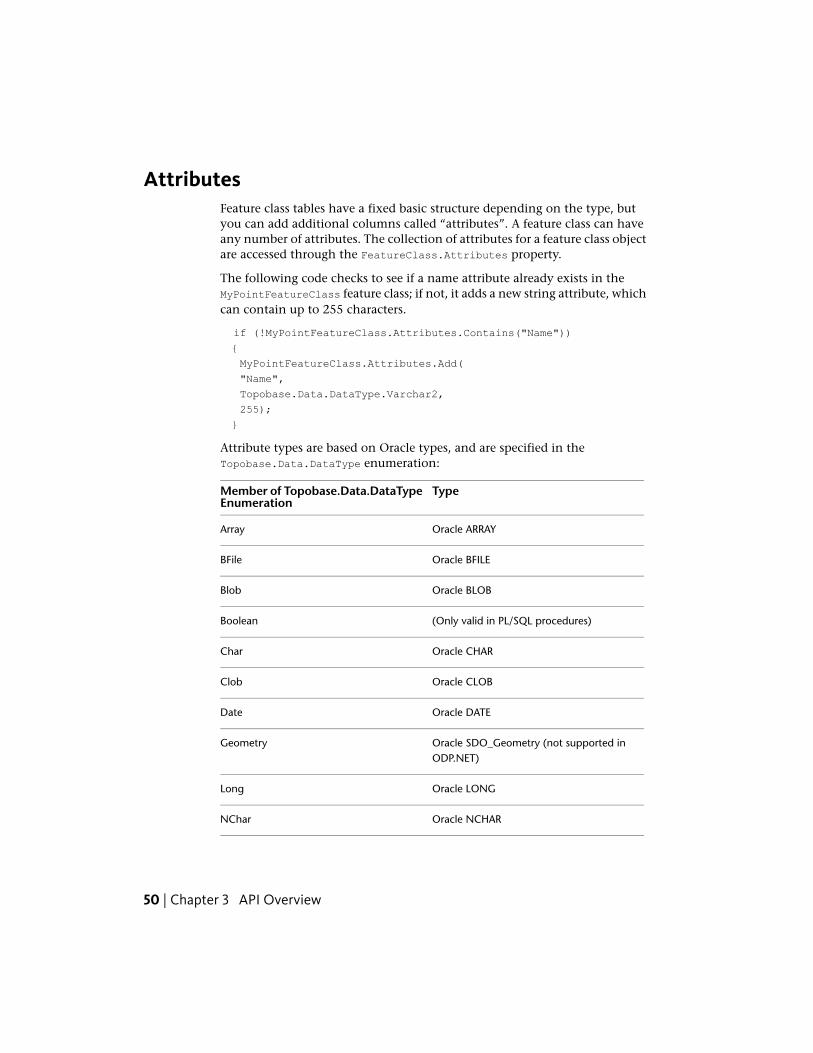
AttributesFeature class tables have a fixed basic structure depending on the type, butyou can add additional columns called “attributes”. A feature class can haveany number of attributes. The collection of attributes for a feature class objectare accessed through the FeatureClass.Attributes property.
The following code checks to see if a name attribute already exists in theMyPointFeatureClass feature class; if not, it adds a new string attribute, whichcan contain up to 255 characters.
if (!MyPointFeatureClass.Attributes.Contains("Name"))
{
MyPointFeatureClass.Attributes.Add(
"Name",
Topobase.Data.DataType.Varchar2,
255);
}
Attribute types are based on Oracle types, and are specified in theTopobase.Data.DataType enumeration:
TypeMember of Topobase.Data.DataTypeEnumeration
Oracle ARRAYArray
Oracle BFILEBFile
Oracle BLOBBlob
(Only valid in PL/SQL procedures)Boolean
Oracle CHARChar
Oracle CLOBClob
Oracle DATEDate
Oracle SDO_Geometry (not supported inODP.NET)
Geometry
Oracle LONGLong
Oracle NCHARNChar
50 | Chapter 3 API Overview
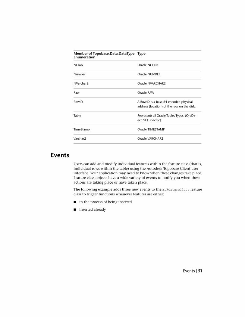
TypeMember of Topobase.Data.DataTypeEnumeration
Oracle NCLOBNClob
Oracle NUMBERNumber
Oracle NVARCHAR2NVarchar2
Oracle RAWRaw
A RowID is a base 64-encoded physicaladdress (location) of the row on the disk.
RowID
Represents all Oracle Tables Types. (OraDir-ect.NET specific)
Table
Oracle TIMESTAMPTimeStamp
Oracle VARCHAR2Varchar2
EventsUsers can add and modify individual features within the feature class (that is,individual rows within the table) using the Autodesk Topobase Client userinterface. Your application may need to know when these changes take place.Feature class objects have a wide variety of events to notify you when theseactions are taking place or have taken place.
The following example adds three new events to the myFeatureClass featureclass to trigger functions whenever features are either:
■ in the process of being inserted
■ inserted already
Events | 51
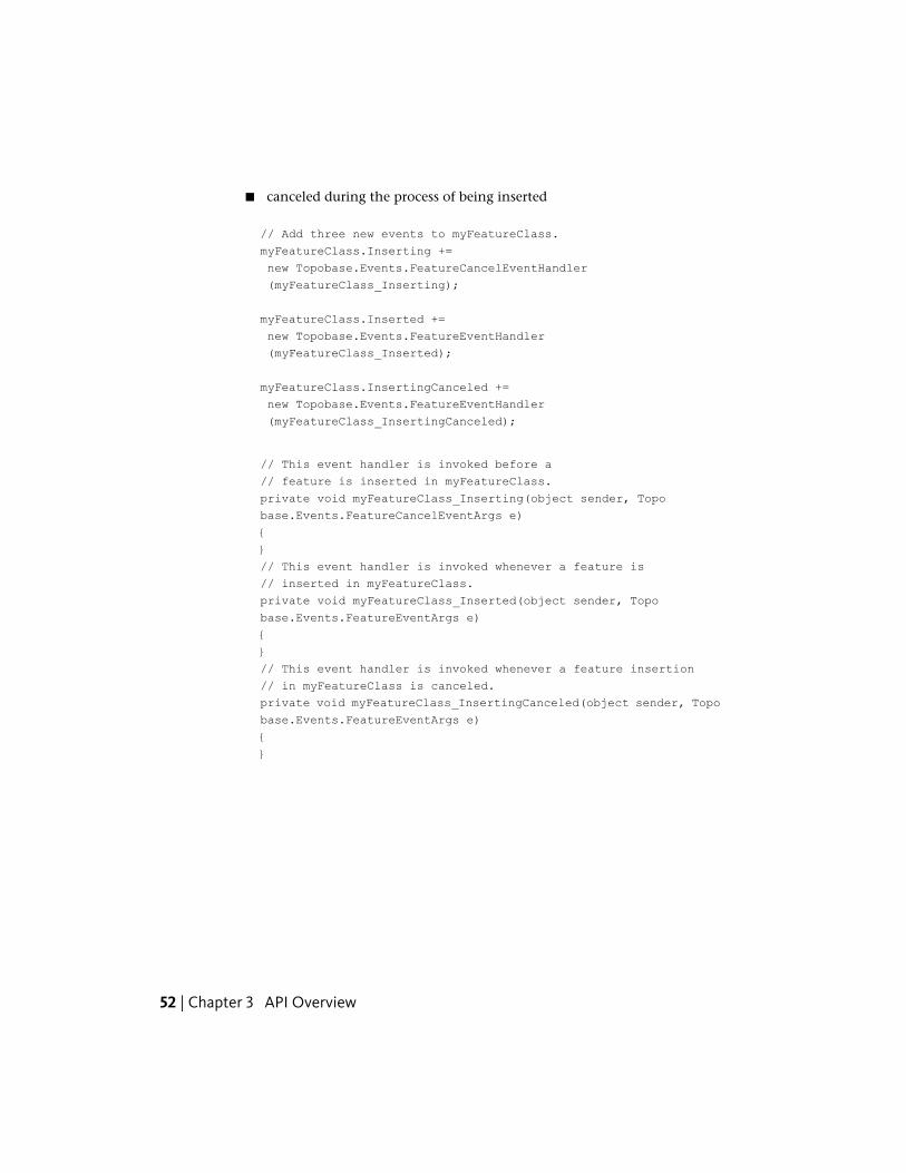
■ canceled during the process of being inserted
// Add three new events to myFeatureClass.
myFeatureClass.Inserting +=
new Topobase.Events.FeatureCancelEventHandler
(myFeatureClass_Inserting);
myFeatureClass.Inserted +=
new Topobase.Events.FeatureEventHandler
(myFeatureClass_Inserted);
myFeatureClass.InsertingCanceled +=
new Topobase.Events.FeatureEventHandler
(myFeatureClass_InsertingCanceled);
// This event handler is invoked before a
// feature is inserted in myFeatureClass.
private void myFeatureClass_Inserting(object sender, Topo
base.Events.FeatureCancelEventArgs e)
{
}
// This event handler is invoked whenever a feature is
// inserted in myFeatureClass.
private void myFeatureClass_Inserted(object sender, Topo
base.Events.FeatureEventArgs e)
{
}
// This event handler is invoked whenever a feature insertion
// in myFeatureClass is canceled.
private void myFeatureClass_InsertingCanceled(object sender, Topo
base.Events.FeatureEventArgs e)
{
}
52 | Chapter 3 API Overview
Feature Class Sample CodeThe following sample code demonstrates a typical action you might do withfeature classes. It first creates a connection to the database, gets a reference toan existing feature class, and then adds a series of attributes to it.
Feature Class Sample Code | 53
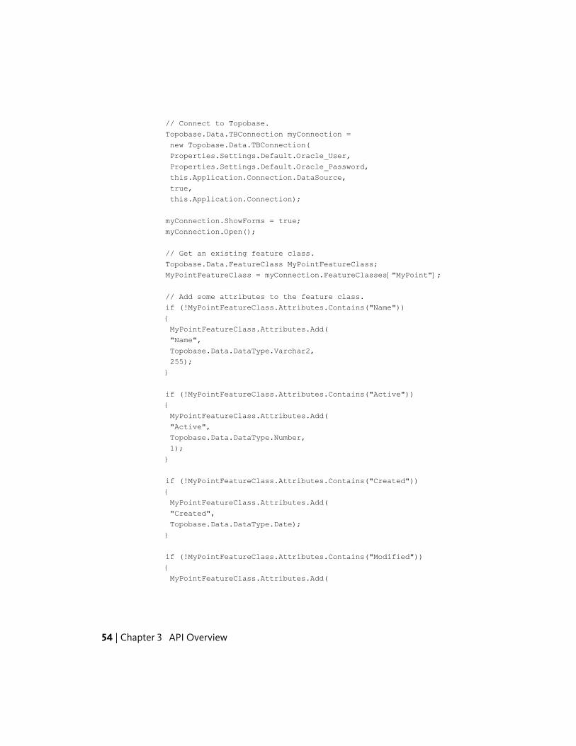
// Connect to Topobase.
Topobase.Data.TBConnection myConnection =
new Topobase.Data.TBConnection(
Properties.Settings.Default.Oracle_User,
Properties.Settings.Default.Oracle_Password,
this.Application.Connection.DataSource,
true,
this.Application.Connection);
myConnection.ShowForms = true;
myConnection.Open();
// Get an existing feature class.
Topobase.Data.FeatureClass MyPointFeatureClass;
MyPointFeatureClass = myConnection.FeatureClasses["MyPoint"];
// Add some attributes to the feature class.
if (!MyPointFeatureClass.Attributes.Contains("Name"))
{
MyPointFeatureClass.Attributes.Add(
"Name",
Topobase.Data.DataType.Varchar2,
255);
}
if (!MyPointFeatureClass.Attributes.Contains("Active"))
{
MyPointFeatureClass.Attributes.Add(
"Active",
Topobase.Data.DataType.Number,
1);
}
if (!MyPointFeatureClass.Attributes.Contains("Created"))
{
MyPointFeatureClass.Attributes.Add(
"Created",
Topobase.Data.DataType.Date);
}
if (!MyPointFeatureClass.Attributes.Contains("Modified"))
{
MyPointFeatureClass.Attributes.Add(
54 | Chapter 3 API Overview
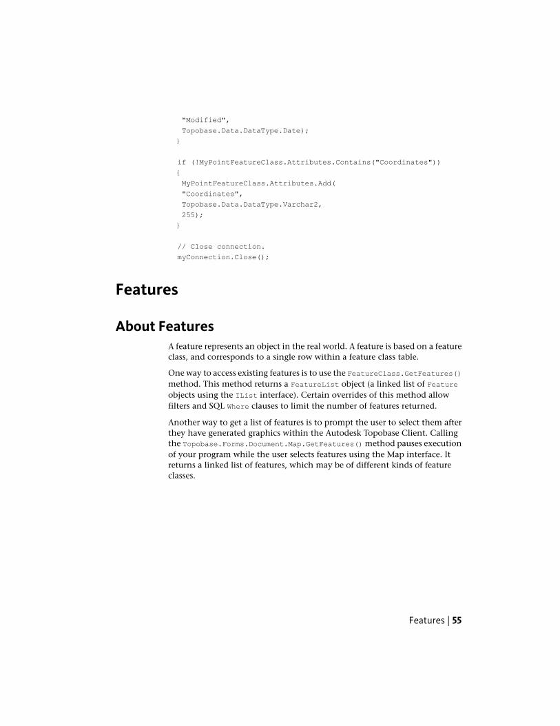
"Modified",
Topobase.Data.DataType.Date);
}
if (!MyPointFeatureClass.Attributes.Contains("Coordinates"))
{
MyPointFeatureClass.Attributes.Add(
"Coordinates",
Topobase.Data.DataType.Varchar2,
255);
}
// Close connection.
myConnection.Close();
Features
About FeaturesA feature represents an object in the real world. A feature is based on a featureclass, and corresponds to a single row within a feature class table.
One way to access existing features is to use the FeatureClass.GetFeatures()method. This method returns a FeatureList object (a linked list of Featureobjects using the IList interface). Certain overrides of this method allowfilters and SQL Where clauses to limit the number of features returned.
Another way to get a list of features is to prompt the user to select them afterthey have generated graphics within the Autodesk Topobase Client. Callingthe Topobase.Forms.Document.Map.GetFeatures() method pauses executionof your program while the user selects features using the Map interface. Itreturns a linked list of features, which may be of different kinds of featureclasses.
Features | 55
Creating FeaturesTo create a new blank feature, call the FeatureClass.CreateFeature() method.This reserves a unique key or feature identifier (FID) for the feature.
// Get the FeatureClass
Topobase.Data.FeatureClass myPointClass =
myConnection.FeatureClasses["MYPOINT"];
// Create a new Feature
Topobase.Data.Feature myPointFeature =
myPointClass.CreateFeature();
Once the feature instance is created, set its properties. For example, you canadd geometry to the feature through the Feature.Geometry property:
myPointFeature.Geometry = new Topobase.Graphic.Point(100, 100);
To insert the new feature into Autodesk Topobase (that is, create a new recordin the feature class table), use the FeatureClass.InsertFeature() method:
myPointClass.InsertFeature(ref myPointFeature);
To update an existing feature in Autodesk Topobase, use theFeatureClass.UpdateFeature() method :
myPointFeature.Geometry = new Topobase.Graphic.Point(200, 200);
// Now that a property has been changed, the feature needs to
// be updated.
myPointClass.UpdateFeature(ref myPointFeature);
To delete an existing feature from Autodesk Topobase, use theFeatureClass.DeleteFeature() method, which requires the identifier of thefeature to be deleted.
bool success = myPointClass.DeleteFeature(myPointFeature.ID);
GeometryThis section explains the geometry of features and the namespaces that helpin examining, computing, and manipulating geometric objects.
56 | Chapter 3 API Overview
Graphic NamespaceThe Topobase.Graphic namespace contains the most importantgeometry-related classes. The Geometry property of feature objects contain anobject based on one of the classes in this namespace.
NOTE Be sure to reference Topobase.Graphic.dll in any project that uses thisnamespace.
GeometriesAll of the geometries in the Topobase.Graphic namespace are derived fromthe abstract base class Topobase.Graphic.Geometry and contains featurescommon to all the geometries. You will frequently see properties andparameters of type Geometry in the rest of the Autodesk Topobase API.
The following table lists the different geometric classes in the namespace:
TopologyClass
A 3D point, used as part of a LineString or Polygon.LinePoint
A collection of LinePoints which form a single connected seriesof line segments.
LineString
A collection of separate LineStrings.MultiLineString
A collection of Points.MultiPoint
A collection of Polygons.MultiPolygon
A 3D point.Point
A LineString where the last point is also connected to the firstpoint, forming a closed figure.
Polygon
A collection of ordinates. Can be used to store geometries thatare not supported by Oracle Spatial.
Unknown
All classes have a bounding box property of typeTopobase.Graphic.BoundingBox, which describes the furthest limits of thepoints in the X, Y, and Z dimensions. For classes that only contain a single
Graphic Namespace | 57
point, all of the bounding box coordinates are set equal to the coordinates ofthe point.
These classes have very few methods for geometry analysis, limited to findingthe distance between points or determining whether a point is located withina bounding box.
TIP For more advanced analysis, such as determining intersections and distancesbetween geometries, you need to convert the geometries into objects from the2D PlaneGeometry Namespace (page 61) or 3D SpaceGeometry Namespace(page 66).
The following code is from a plugin or workflow, and uses the plugin orworkflow’s base object to have the user select two points. The distance betweenthe two points is determined.
Topobase.Graphic.Point point1 =
this.Document.Map.GetPoint("Select Point 1");
Topobase.Graphic.Point point2 =
this.Document.Map.GetPoint("Select Point 2");
double distance = point1.Distance2D(point2);
Accessing the Geometry Property of a Feature
Point Geometry
The Topobase.Graphic.Point class represents a single 3D point location. Thecoordinates are stored in parameters named X, Y, and Z, which can also be setin the class constructor. The Z coordinate has a default value of zero (0).
The following code assigns a point with the X, Y, and Z coordinates “1234.5,678.9, 0.0” to a feature:
pointFeature.Geometry = new Topobase.Graphic.Point(1234.5, 678.9);
LineString and Polygon Geometry
Topobase.Graphic.LineString and Topobase.Graphic.Polygon both consistof a collection of Topobase.Graphic.LinePoint objects. LinePoints are addedto the collection one at a time using the Add() method (which adds the pointto the end of the list of points) or the Insert() method (which inserts thepoint at the specified index in the existing list of points). LinePoints can alsobe added as a group by passing any collection of LinePoint objects that supports
58 | Chapter 3 API Overview
the IEnumerable interface (such as a List or ArrayList) in the LineString orPolygon constructor or to the AddRange() method.
Like a Point, a LinePoint represents a single 3D point location and has X, Y,and Z parameters. It also has an Interpretation parameter, which describesthe nature of the lines formed by the points. By default, LinePoints representendpoints of straight line segments. LinePoints can also form arcs with oneLinePoint representing the starting point of the arc (with the Interpretationparameter set to Topobase.Graphic.Interpretations.ArcStart), the nextLinePoint representing a midpoint which the arc passes through (with theInterpretation parameter set toTopobase.Graphic.Interpretations.ArcMidpoint), and the last LinePointrepresenting the end point of the arc (with the Interpretation parameter setto Topobase.Graphic.Interpretations.ArcEnd). If two arcs are adjacent toeach other, then the LinePoint separating the two arcs should be set toArcStart.
The following code creates a Polygon consisting of three straight line segmentsand assigns it to the Geometry property of a feature:
// Create the Polygon geometry.
Topobase.Graphic.Polygon polygonGeometry =
new Topobase.Graphic.Polygon();
polygonGeometry.Add(new Topobase.Graphic.LinePoint(15, 27));
polygonGeometry.Add(new Topobase.Graphic.LinePoint(11, 26));
polygonGeometry.Add(new Topobase.Graphic.LinePoint(20, 11));
// Add Geometry to the Feature.
polygonFeature.Geometry = polygonGeometry;
Graphic Namespace | 59
The following code creates a LineString consisting of two arc line segmentsand assigns it to the Geometry property of a feature:
// Create the LineString geometry.
Topobase.Graphic.LineString lineGeometry =
new Topobase.Graphic.LineString();
lineGeometry.Add(new Topobase.Graphic.LinePoint(5, 10,
Topobase.Graphic.Interpretations.ArcBegin));
lineGeometry.Add(new Topobase.Graphic.LinePoint(10, 26,
Topobase.Graphic.Interpretations.ArcMidpoint));
// The end of the first arc and the start of the second.
lineGeometry.Add(new Topobase.Graphic.LinePoint(20, 13,
Topobase.Graphic.Interpretations.ArcBegin));
lineGeometry.Add(new Topobase.Graphic.LinePoint(27, 7,
Topobase.Graphic.Interpretations.ArcMidpoint));
lineGeometry.Add(new Topobase.Graphic.LinePoint(31, 20,
Topobase.Graphic.Interpretations.ArcEnd));
// Add Geometry to the Feature
lineFeature.Geometry = lineGeometry;
Polygons can also contain holes. Each hole is defined by a separate Polygonobject. New holes are added to the collection of holes using the AddHole()method.
// Create a triangular polygon for the hole.
List<LinePoint> lpList = new List<LinePoint>();
lpList.Add(new LinePoint(5, 5));
lpList.Add(new LinePoint(15, 5));
lpList.Add(new LinePoint(10, 15));
Polygon holePolygon = new Polygon(lpList);
// Assume outerPolygon already created and defined with line
// segments that fully enclose holePolygon.
outerPolygon.AddHole(holePolygon);
MultiLineString Geometry
Topobase.Graphic.MultiLineString consists of a collection ofTopobase.Graphic.LineString objects. LineStrings are added to the collectionone at a time using the Add() method (which adds the LineString to the endof the list of LineStrings) or the Insert() method (which inserts the LineString
60 | Chapter 3 API Overview
at the specified index in the existing list of LineStrings). LineStrings can alsobe added as a group by passing any collection of LineString objects thatsupports the IEnumerable interface (such as a List or ArrayList) in theMultiLineString constructor.
MultiPolygon Geometry
Topobase.Graphic.MultiPolygon consists of a collection ofTopobase.Graphic.Polygon objects. Polygons are added to the collection oneat a time using the Add() method (which adds the polygon to the end of thelist of polygons) or the Insert() method (which inserts the polygon at thespecified index in the existing list of polygons). Polygons can also be addedas a group by passing any collection of Polygon objects that supports theIEnumerable interface (such as a List or ArrayList) in the MultiPolygonconstructor.
PlaneGeometry NamespaceThe Topobase.PlaneGeometry namespace consists of a series of classes thatrepresent simple 2D geometric objects. These classes allow you to performmany kinds of geometric analysis not possible with the objects in the basicGraphic Namespace (page 57).
NOTE Be sure to reference Topobase.PlaneGeometry.dll in any project that usesthis namespace.
Overview of PlaneGeometryTopobase.PlaneGeometry includes classes for many different kinds of simpleand compound figures. These classes are all immutable, meaning that theycannot be added to or modified after they have been constructed with theexception of inner rings for polygons. Figures are created by either using theclass constructor or by using the static TryCreate() method in each of thefollowing classes:
DescriptionClass Name
An arc connecting two points, which canform part of a Line2D or Polygon2D.
ArcSegment2D
A circle, created using either a point anda radius, or an arc segment.
Circle2D
PlaneGeometry Namespace | 61
DescriptionClass Name
A contiguous series of ArcSegment2D andStraightSegment2D objects.
Line2D
Abstract base class of ArcSegment2D andStraightSegment2D.
LineSegment2D
A Line2D converted to take up lessmemory, but which does not allow you todirectly access the constituent segments.
PackedLine2D
A Polygon2D converted to take up lessmemory, but which does not allow you todirectly access the constituent segments.
PackedPolygon2D
A continuous series of ArcSegment2D andStraightSegment2D objects forming a
Polygon2D
closed figure. Holes can be added after thepolygon has been constructed.
A straight line.Straight2D
A straight line segment connecting twopoints, which can form part of a Line2Dor Polygon2D.
StraightSegment2D
There are also two structures representing the basic elements of position anddirection:
DescriptionStructure Name
A structure representing a point location.Point2D
A structure representing a vector.Vector2D
62 | Chapter 3 API Overview
Creating PlaneGeometry Objects From Graphic ObjectsSome of the classes in the Topobase.Graphic namespace have methods thatdirectly create equivalent PlaneGeometry objects that have been flattened onthe Z axis.
Method for Creating Topobase.PlaneGeometryObject
Topobase.Graphic Ob-ject
ToPoint2D()Point
ToPoint2D()LinePoint
ToLine2D()LineString
ToLine2D(), ToPolygon2D()Polygon
These methods make it easy to perform analysis and mathematical operationson Topobase.Graphic objects. The following example determines the area ofa Topobase.Graphic.Polygon object:
// Given a valid Topobase.Graphic.Polygon object named tmpPoly,
// compute the area of this polygon.
Topobase.PlaneGeometry.Polygon2D poly2D = tmpPoly.ToPolygon2D();
double area = poly2D.CalculateArea();
Those classes that are made up of collections of single geometries (MultiPoint,MultiLine, MultiPolygon) do not have direct methods for creatingPlaneGeometry objects. Instead, you need to look through all the items in thecollection and call the method for creating those objects for each item in thecollection.
PlaneGeometry Namespace | 63
The following code snippet determines the total length of all LineStringgeometries within a MultiLineString object:
Topobase.Graphic.MultiLineString river =
new Topobase.Graphic.MultiLineString();
//
// NOT SHOWN - Assigning LineStrings to "river".
//
double totalLength = 0.0;
foreach (Topobase.Graphic.LineString bank in river)
{
Topobase.PlaneGeometry.Line2D bank2D = bank.ToLine2D();
totalLength += bank2D.CalculateLength();
}
Moving, Scaling, and Rotating PlaneGeometry ObjectsThe Topobase.PlaneGeometry.AffineTransformation class provides amechanisms for moving, scaling, and rotating PlaneGeometry objects. Firstcreate an AffineTransformation object with the correct series oftransformations, and then call the Transform() method, which takes in eithera Circle2D, Line2D, Point2D, Polygon2D, or Straight2D object, and returns anew transformed object of the same type.
64 | Chapter 3 API Overview
For a simple transformation, you can create a new AffineTransformationobject by calling one of the static creation methods: CreateMirror(),CreateRotation(), CreateScaling(), or CreateTranslation().
// Create transformation that rotates by PI/2 around the origin
// point.
// Use the provided constant to get PI/2.
double angle = Topobase.PlaneGeometry.Vector2D.PiHalf;
Topobase.PlaneGeometry.AffineTransformation rotation;
rotation = Topobase.PlaneGeometry.AffineTransformation.
CreateRotation(angle);
Topobase.PlaneGeometry.Polygon2D oldPolygon;
//
// NOT SHOWN - Creating a polygon object and assigning
// line segments to it.
//
Topobase.PlaneGeometry.Polygon2D newPolygon;
newPolygon = rotation.Transform(oldPolygon);
// Now newPolygon is a new Polygon2D object that is exactly
// like oldPolygon except it has been rotated PI/2 around the
// origin point.
To perform a series of transformations, create an instance of theAffineTransformation object and add each transformation in turn using the
PlaneGeometry Namespace | 65
MirrorAt(), RotateBy(), ScaleBy(), and TranslateBy() methods. Thetransformations are performed in the order they are added.
// Create transformation that first scales the object by
// a factor of 2, and then moves it 10 units along the X axis.
Topobase.PlaneGeometry.AffineTransformation transform1;
transform1 = new Topobase.PlaneGeometry.AffineTransformation();
transform1.ScaleBy(2.0);
Topobase.PlaneGeometry.Vector2D v;
v.X = 10.0;
transform1.TranslateBy(v);
Topobase.PlaneGeometry.Polygon2D oldPolygon;
//
// NOT SHOWN - Creating a polygon object and assigning
// line segments to it.
//
Topobase.PlaneGeometry.Polygon2D newPolygon;
newPolygon = transform1.Transform(oldPolygon);
TIP AffineTransformation objects can also be combined using the CombineWith()method. The order of transformations in an AffineTransformation object can bereversed by calling the Reverse() method.
SpaceGeometry NamespaceThe Topobase.SpaceGeometry namespace is the 3D equivalent ofPlaneGeometry, and consists of a series of classes that represent simple 3Dgeometric objects. These classes allow you to perform many kinds of geometricanalysis not possible with the objects in the basic Graphic Namespace (page57).
NOTE Be sure to reference Topobase.SpaceGeometry.dll in any project that usesthis namespace.
Overview of SpaceGeometryTopobase.SpaceGeometry includes classes for many different kinds of simpleand compound figures. These classes are all immutable, meaning that theycannot be added to or modified after they have been constructed with theexception of inner rings for polygons. Figures are created by either using the
66 | Chapter 3 API Overview
class constructor or by using the static TryCreate() method in each of thefollowing classes:
DescriptionClass Name
A group of geometries with similar charac-teristics.
Cluster
A contiguous series of StraightSegment3Dobjects.
Line3D
A Line3D converted to take up lessmemory, but which does not allow you todirectly access the constituent segments.
PackedLine3D
A contiguous series of StraightSegment3Dobjects forming a closed figure. Holes can
Polygon3D
be added after the polygon has been con-structed.
A sphere created using a Point3D and aradius.
Sphere3D
A straight line.Straight3D
A straight line segment connecting twopoints in 3D space, which can form partof a Line3D or Polygon3D.
StraightSegment3D
There are also two structures representing the basic elements of position anddirection:
DescriptionStructure Name
A structure representing a point locationin 3D space.
Point3D
A structure representing a vector in 3Dspace.
Vector3D
SpaceGeometry Namespace | 67
Creating SpaceGeometry Objects From Graphic ObjectsSome of the classes in the Topobase.Graphic namespace have methods thatdirectly create equivalent SpaceGeometry objects.
Method for Creating Topobase.SpaceGeometryObject
Topobase.Graphic Ob-ject
ToPoint3D()Point
ToPoint3D()LinePoint
ToLine3D()LineString
ToLine3D(), ToPolygon3D()Polygon
These methods make it easy to perform analysis and mathematical operationson Topobase.Graphic objects. The following example determines the 3D areaof a Topobase.Graphic.Polygon object:
// Given a valid Topobase.Graphic.Polygon object named tmpPoly,
// compute the area of this polygon.
Topobase.SpaceGeometry.Polygon3D poly = tmpPoly.ToPolygon3D();
double area = poly.CalculateArea();
Those classes that are made up of collections of single geometries (MultiPoint,MultiLine, MultiPolygon) do not have direct methods for creatingPlaneGeometry objects. Instead, you need to look through all the items in thecollection and call the method for creating those objects for each item in thecollection.
The following code snippet determines the total length of all LineStringgeometries within a MultiLineString object:
Topobase.Graphic.MultiLineString river =
new Topobase.Graphic.MultiLineString();
//
// NOT SHOWN - Assigning LineStrings to "river".
//
double totalLength = 0.0;
foreach (Topobase.Graphic.LineString bank in river)
{
Topobase.SpaceGeometry.Line3D bank3D = bank.ToLine3D();
totalLength += bank3D.CalculateLength();
}
68 | Chapter 3 API Overview
Creating Graphic Objects From GeometryOnce you have created a PlaneGeometry or SpaceGeometry object, you cancreate an equivalent Graphic object using the Topobase.Graphic.GeomFactoryclass. First, you get an instance of this class by accessing the static Defaultproperty - GeomFactory has no new constructor. You then call theBuildGeometry() method with a Point2D, Line2D, Polygon2D, Point3D, Line3D,or Polygon3D as the parameter. The function returns a new Graphic.Point,Graphic.Line, or Graphic.Polygon as appropriate.
The following sample code gets the polygon geometry of a feature, convertsit into a Polygon2D, and scales it by a factor of 2. It then uses that Polygon2Dto create a Graphic.Polygon object using GeomFactory.
// Get the polygon geometry of a feature named "feature1".
Topobase.Graphic.Polygon tPolygon =
feature1.Geometry as Topobase.Graphic.Polygon;
Topobase.PlaneGeometry.Polygon2D planePoly =
tPolygon.ToPolygon2D();
// Use AffineTransformation to scale the polygon.
Topobase.PlaneGeometry.AffineTransformation scale;
scale =
Topobase.PlaneGeometry.AffineTransformation.CreateScaling(2.0);
planePoly = scale.Transform(planePoly);
// Use GeomFactory to create a new Polygon called "graphicPoly".
Topobase.Graphic.GeomFactory gFactory =
Topobase.Graphic.GeomFactory.Default;
Topobase.Graphic.Polygon graphicPoly;
graphicPoly = gFactory.BuildGeometry(planePoly);
TopologiesThere are two main kinds of topologies available in Topobase: logical topologiesand area topologies. The collection of all topology objects is obtained fromthe TBConnection.Topologies property.
Creating Graphic Objects From Geometry | 69
Topology Related AssembliesWhen creating projects that deal with topologies, you need to includeassemblies from the following list:
■ Topobase.LogicalTopology.dll contains classes to create, modify and analyzelogical topologies. It also contains logical topology-specific implementationsof the tracing algorithms.
■ Topobase.LogicalToplogy.FeatureRules.dll contains the classes that can helpyou automatically update the topology if users add, update, or removefeatures.
■ Topobase.AreaTopology.dll contains classes to create, modify, and analyzearea topologies.
■ Topobase.AreaTopology.FeatureRules.dll contains the classes that can helpyou automatically update the topology if users add, update, or removefeatures.
■ Topobase.Tracing.dll contains the base network tracing classes and interfacesand the basic implementation of tracing algorithms, which are used bythe tracing functionality of the Topobase.LogicalTopology andTopobase.AreaTopology namespaces.
■ Topobase.Data.dll defines all the base metadata classes (topologies, featureclasses, features) used throughout the Topobase.LogicalTopology andTopobase.AreaTopology namespaces.
Logical TopologiesLogical topologies connect features of any feature classes. The features do notneed to be spatially connected. A logical topology can connect points withpoints, or lines with lines, or lines with points, or attribute features withattribute features. For example, a logical topology can represent a waste waternetwork or electrical transmission lines.
A network topology is a subtype of a logical topology that is limited to lines,which are geometrically connected to each other at point nodes. AutodeskTopobase utility models are based on logical topologies that connect pointsand lines.
Topologies are maintained at the client-side using feature rules. For moreinformation about feature rules, see Autodesk Topobase Feature Rule Reference(TopobaseFeatureRuleReference.chm).
70 | Chapter 3 API Overview
LogicalTopology as Namespace and ClassIt is important to note that LogicalTopology is both the name of a namespaceand the name of a class in the Topobase.Data namespace. This means thatthis class must be fully qualified in your code (that is, always specified as“Topobase.Data.Doc.Topologies.LogicalTopology” instead of simply“LogicalTopology”). One remedy is to add the following line to your code:
using Topobase.Data.Doc.Topologies as TDDT;
You can then just write TDDT.LogicalTopology instead of the fully qualifiedname.
Initializing Logical TopologiesInitializing logical topologies is done with theTopobase.LogicalTopology.Maintainance object. Create a new instance ofthe maintenance object, use the InitializeTopology method, and disposethe maintenance object. One way to make sure the disposal is handled correctlyis to use the using keyword. Initializing a logical topology is a little more
Logical Topologies | 71
involved than an area topology because you need to account for possiblethird-party plugins that change how the topology behaves. For example:
// Initialize logical topology.
using (Topobase.LogicalTopology.Maintainance ma =
new Topobase.LogicalTopology.Maintainance(myConnection))
{
// Try to get third-party plugins that change the behavior
// of the topology.
Topobase.LogicalTopology.Initialization.
ITopologyInitializationLogic logic = null;
Topobase.LogicalTopology.FeatureRules.
LogicalTopologyRules rules;
if (Topobase.LogicalTopology.FeatureRules.
LogicalTopologyRules.TryGetPlugIn(myConnection, out rules))
{
logic = rules.GetInitializationLogicFor(topology);
}
// Initialize the topology using the found plugins.
ma.InitializeTopology (topology, logic, null);
}
Area TopologiesArea topologies are typically used to model surfaces or parcels. An area topologyis made up of non-overlapping areas represented by closed polygons made upof line and polyline features. Each area also contains a point featurerepresenting the polygon centroid.
Initializing Area TopologiesInitializing area topologies is done with theTopobase.AreaTopology.Maintainance object. Create a new instance of themaintenance object, use the InitializeTopology method, and dispose the
72 | Chapter 3 API Overview

maintenance object. One way to make sure the disposal is handled correctlyis to use the using keyword, as in the following example:
// Initialize area topology.
using (Topobase.AreaTopology.Maintainance ma =
new Topobase.AreaTopology.Maintainance(myConnection))
{
ma.InitializeTopology (topology, null);
}
Area Topologies | 73

74
Quick Guide: Creating aTopobase Plugin
IntroductionThe instructions in this chapter guide you step-by-step through the process ofcreating an Autodesk Topobase plugin that modifies the Autodesk Topobaseuser interface. For a more detailed description of user interface plugins, seeCreating User Interface Plugins (page 133).
C# is used in the following example, but all .NET programming languages canbe used to create plugins.
NOTE Over 70 samples are provided in both C# and Visual Basic, located under<Topobase Install Directory>\Development\Samples, which are documented inDeveloper Samples (page 179).
In this example, you will create a new document menu item by performing thefollowing tasks:
■ Create a new Visual Studio C# project that builds a class library (that is, afile with a “.dll” extension).
■ Configure the project so that your plugin and the related files are writtento the bin folder in the Autodesk Topobase install folder when you buildyour project.
■ Configure the project so that Autodesk Topobase is started when you runyour plugin from Visual Studio.
■ Configure the project with the class references your plugin class needs.
4
75
■ Review the assembly properties to verify that the default values are valid.
■ Add code to the default class.
■ Create a Autodesk Topobase plugin definition file (identified by the .tbpextension) so that Autodesk Topobase knows about your plugin.
■ Test your plugin.
The intent of the plugin is to add a menu item to the context menu withinthe Document Explorer in the Autodesk Topobase task pane. Selecting themenu item causes a message box to be displayed with the common “HelloWorld” text.
IMPORTANT Testing this plugin requires a workspace containing feature classesbased on the Point feature class type. A suitable workspace for testing the pluginis the TB2009_LM_102 Land Management demonstration workspace. The creationof this workspace is described in the Autodesk Topobase Installation and ConfigurationGuide. Alternatively, another suitable workspace is the TBSAMPLE workspacedescribed in Sample 01 - Create Structure (page 182).
Creating a New ProjectThis procedure describes how to create a new C# class library project. AllAutodesk Topobase plugin types are based on class libraries.
1 Start Microsoft Visual Studio.
2 Click File ➤ New ➤ Project. The New Project dialog box is displayed.
3 In the New Project dialog box in the Project Types pane, click the VisualC# node.
4 In the Templates pane, click Class Library.
5 In the Name text box, type “MyTopobasePluginProject”.
6 Set the path to the project folder by using the Location selection box orby clicking the Browse... button.
7 To close the New Project dialog box and create a new blank solution,click OK.
The Solution Explorer pane is now populated with a solution node as rootwith a project subnode. The project node has two subnodes: My Project and
76 | Chapter 4 Quick Guide: Creating a Topobase Plugin
Class1.cs. The editor pane is populated with a Class1.cs tab, and the contentsof this tab is a skeleton class declaration:
class Class1
{
}
Accessing the Project PropertiesTo configure your project for use with Autodesk Topobase, you must edit theVisual Studio project properties. This brief procedure describes how to displaythe required panel and shows an example image. Specific information aboutconfiguring the properties starts with Configuring the Project to Write theBuild Outputs to the Topobase Bin Folder (page 78).
To display the Visual Studio project properties:
■ In the Solution Explorer pane, right-click the project node and selectProperties.
The result is that the project properties are displayed in a tab in the Editorpane. The tab label is the name of the project. The contents of this tab is a setof vertical tabs on the left and a display area on the right. Depending on yourVisual Studio configuration, the vertical tabs are from top to bottom:Application, Compile, Debug, References, Resources, Settings, and Signing(and possibly, Security, and Publish). Clicking a vertical tab causes the displayof related properties in the display area on the right.
Accessing the Project Properties | 77
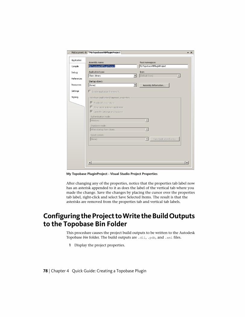
My Topobase PluginProject - Visual Studio Project Properties
After changing any of the properties, notice that the properties tab label nowhas an asterisk appended to it as does the label of the vertical tab where youmade the change. Save the changes by placing the cursor over the propertiestab label, right-click and select Save Selected Items. The result is that theasterisks are removed from the properties tab and vertical tab labels.
Configuring the Project to Write the Build Outputsto the Topobase Bin Folder
This procedure causes the project build outputs to be written to the AutodeskTopobase bin folder. The build outputs are .dll, .pdb, and .xml files.
1 Display the project properties.
78 | Chapter 4 Quick Guide: Creating a Topobase Plugin
2 In the properties tab, click the Compile vertical tab.
3 If required, change configuration to All Configurations.
4 To the right of the Build Output Path text box, click the Browse... button.
5 In the Select Output Path dialog box browse to the location of theAutodesk Topobase bin folder. The path is typically C:\ProgramFiles\Autodesk Topobase Client <yyyy>\bin, where <yyyy> is the AutodeskTopobase version. Click Open. This causes the path that you selected tobe written to the Build Output Path text box.
6 Save the properties.
Configuring the Project to Run Topobase fromVisual Studio
This procedure causes Autodesk Topobase to run automatically when you startdebugging your project in Visual Studio. This allows you to debug the pluginwhile Autodesk Topobase is running. You can place breakpoints in the codeand use the “Edit and Continue” feature of Visual Studio .NET to make changesto your code without exiting Autodesk Topobase.
1 Display the project properties.
2 In the properties tab, click the Debug vertical tab.
3 If required, change configuration to All Configurations.
4 In the Start Action set of radio buttons, click the Start External Programradio button.
5 To the right of the text area for this radio button, click the Browse...button.
6 In the Select File dialog box, browse to the location of the AutodeskTopobase executable. This path is typically C:\Program Files\AutodeskTopobase Client <yyyy>, where <yyyy> is the Autodesk Topobase version.Select acad.exe and click Open.
7 Under the Start Options group in the Working Directory text box, typethe location of acad.exe. For this exercise, the location is C:\ProgramFiles\Autodesk Topobase Client <yyyy>, where <yyyy> is the AutodeskTopobase version.
8 Save the properties.
Configuring the Project to Run Topobase from Visual Studio | 79
Adding References To Your ProjectIn order for the project to work properly, you must add a number of AutodeskTopobase class references.
1 In the Solution Explorer pane, right-click on the project node select AddReference....
2 In the Add Reference dialog box, click the Browse tab.
3 Browse to the location of the Autodesk Topobase Client bin folder.Multiselect four files by holding down the Ctrl key, click on the following:
■ Topobase.Data.dll
■ Topobase.Forms.dll
■ Topobase.Graphic.dll
■ Topobase.Map.dll
NOTE Not all plugins require all of these references. Some other kinds ofplugins have their own requirements. For example, workflows require areference to Topobase.Workflows.
4 Click OK.
5 In the Editor pane note that the properties tab label has an asteriskappended to it again. Click the References vertical tab. Note thatTopobase.Data.dll, Topobase.Forms.dll, Topobase.Graphic.dll, andTopobase.Map.dll have all been added to the References list box.
6 In the References list box, do the following for each of these .dll’s:
1 Select it. The result is that the Properties pane is populated with theproperties associated with that .dll.
2 In the Properties pane, select the Copy Local property. This displaysa select control in the box containing the value for this property.
NOTE This also displays help text for that property, which reads:Indicates Whether The Reference Will Be Copied To The OutputDirectory.
3 Use the select control to change the value of this property to False.
80 | Chapter 4 Quick Guide: Creating a Topobase Plugin
4 In the Properties pane, select the Specific Version property. Thisdisplays a select control in the box containing the value for thisproperty.
NOTE This also displays help text for that property, which reads:Indicates Whether This Reference Is To A Specific Version Of An Assembly.
5 Use the select control to change the value of this property to False.
7 Save the properties.
Inspecting the Assembly InformationThis procedure describes how to the inspect the assembly informationgenerated for this project.
1 In the project properties tab, click the Application vertical tab.
2 Click the Assembly Information button, which displays the AssemblyInformation dialog box.
3 Inspect or review the information and click OK.
Adding Code To The Default ClassWhen you created the project, a Class1 default class was created in a Class1.csfile. We want to customize the class and add some code.
To change the name of the class and file to MyDocument:
1 In the Solution Explorer pane, right-click the Class1.cs node and selectRename. The display of the class node’s label is changed to a text box.
2 In the text box, type MyDocument.cs.
3 In the Editor pane, click the tab containing the skeleton class definition.The tab label is changed to MyDocument.cs, and the class name in theskeleton class declaration is changed to MyDocument.
Now, let’s add some code:
1 Modify the class declaration so that it looks like the following:
Inspecting the Assembly Information | 81
public class MyDocument : Topobase.Forms.DocumentPlugIn
{
public Topobase.Forms.MenuItem myMenuItem1 =
new Topobase.Forms.MenuItem();
}
The public declaration of the myMenuItem1 object allows AutodeskTopobase to communicate menu events in the user interface to the plugin.
2 Add the following code to the class. This overrides the event handler,which is called when the Autodesk Topobase document menus are firstinitialized.
public override void OnInitMenus
(object sender, Topobase.Forms.Events.MenusEventArgs e)
{
}
3 Add a menu item to the popup menu by adding the following lines ofcode into the body of the new OnInitMenus subroutine:
NOTE This menu item is only available to point feature class items in the taskpane.
// Obtain the context menu.
Topobase.Forms.Menu pointMenu =
e.Menus.Item(Topobase.Data.FeatureClassType.Point);
// Add the menu item to the context menu.
pointMenu.MenuItems.Add(myMenuItem1, "My Menu Item");
myMenuItem1.Click += new Topobase.Forms.Events.
MenuItemClickEventHandler(MyMenuItem1_Click);
4 Create a handler for menu events by adding the following lines of codebelow the OnInitMenus subroutine:
private void MyMenuItem1_Click
(object sender, Topobase.Forms.Events.MenuItemClickEventArgs
e)
{
}
5 Display a message box when the menu item is clicked by adding thefollowing line of code in the body of new MyMenuItem1_Click subroutine:
this.Application.MessageBox("Hello World");
82 | Chapter 4 Quick Guide: Creating a Topobase Plugin
6 Save the class file. After completing the above steps, the final class shouldlook like the following:
public class MyDocument : Topobase.Forms.DocumentPlugIn
{
public Topobase.Forms.MenuItem myMenuItem =
new Topobase.Forms.MenuItem();
public override void OnInitMenus
(object sender, Topobase.Forms.Events.MenusEventArgs e)
{
// Obtain the context menu.
Topobase.Forms.Menu pointMenu =
e.Menus.Item(Topobase.Data.FeatureClassType.Point);
// Add the menu item to the context menu.
pointMenu.MenuItems.Add(myMenuItem1, "My Menu Item");
myMenuItem1.Click += new Topobase.Forms.Events.
MenuItemClickEventHandler(MyMenuItem1_Click);
}
private void MyMenuItem1_Click
(object sender, Topobase.Forms.Events.MenuItemClickEventArgs
e)
{
this.Application.MessageBox("Hello World");
}
}
Creating a Topobase Plugin Definition FileWhen Autodesk Topobase starts, it reads the plugin definition files in the binfolder to determine what plugins are available.
You can use a text editor to create a file with a .tbp extension. For this example,name the file MyTopobasePlugInProject.tbp. Save it in the project directory withyour source code. Add it to the list of files in the Visual Studio Solution Explorerdialog box.
Creating a Topobase Plugin Definition File | 83
TIP Display the properties of the file and make sure that the “Copy to OutputDirectory” property is set to “Copy Always”. This automatically copies the .tbp fileto the Autodesk Topobase Client bin folder with the .dll whenever you build yourproject.
The contents of the file are as follows:
<?xml version="1.0" encoding="utf-8"?>
<PlugIn>
<Default
AssemblyName="MyTopobasePlugInProject.dll"
Namespace="MyTopobasePlugInProject"
DocumentKey=""
MapName=""
Priority="100"
ExecutionTargetWeb="True"
ExecutionTargetDesktop="True"
/>
<DocumentPlugIn ClassName="MyDocument"/>
</PlugIn>
TIP If you copy the above text and paste it into your MyTopobasePluginProject.tbpfile, ensure that the pasted quotation marks are ASCII-encoded.
NOTE The AssemblyName attribute value is MyTopobasePlugInProject.dll. Bydefault the .dll name is the same as the project name.
Testing the PluginIf the plugin project is configured to start Autodesk Topobase (see Configuringthe Project to Run Topobase from Visual Studio (page 79)), then you can testand debug your plugin from within Visual Studio. You can place breakpointsin the code and use the “Edit and Continue” feature of Visual Studio .NET tomake changes to your code without exiting Autodesk Topobase.
84 | Chapter 4 Quick Guide: Creating a Topobase Plugin
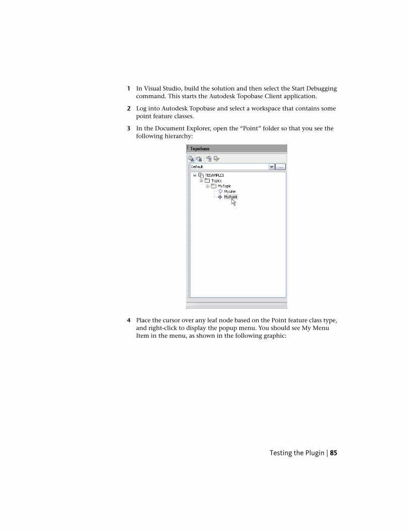
1 In Visual Studio, build the solution and then select the Start Debuggingcommand. This starts the Autodesk Topobase Client application.
2 Log into Autodesk Topobase and select a workspace that contains somepoint feature classes.
3 In the Document Explorer, open the “Point” folder so that you see thefollowing hierarchy:
4 Place the cursor over any leaf node based on the Point feature class type,and right-click to display the popup menu. You should see My MenuItem in the menu, as shown in the following graphic:
Testing the Plugin | 85
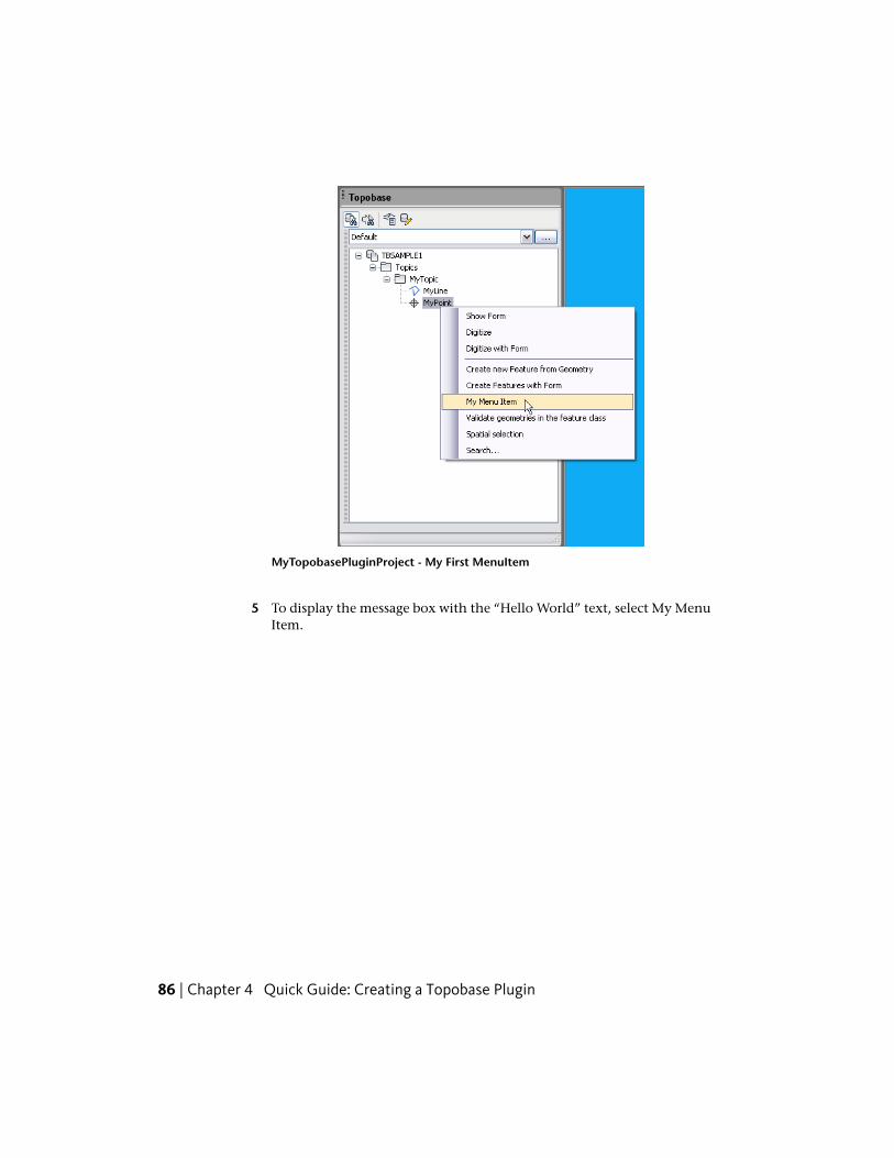
MyTopobasePluginProject - My First MenuItem
5 To display the message box with the “Hello World” text, select My MenuItem.
86 | Chapter 4 Quick Guide: Creating a Topobase Plugin
Creating ApplicationModules
A vertical application module serves as the basis for documents created in the AutodeskTopobase Administrator. An application module defines the data model (topics, tables,attributes, topologies, and so on) and provides tools for manipulating the data model(workflows, plugins, option pages). This chapter describes how to build an application modulebased on the example provided by Sample 117 - Simple Water Module (page 302) and how tocreate plugins and other tools, either as part of the application module or as stand-aloneAutodesk Topobase extensions.
Creating the Data Model
About Data ModelsA vertical application module often needs to create or update a data model, adddomain values to a model, create or update a topology, add workflow definitions,or perform other administrative tasks. A type of plugin called the “structureupdate” plugin is used to perform these actions. If your application moduledoes not need to perform these tasks, then do not include a structure updateplugin as part of the project.
All data model changes that can be done manually in the Autodesk TopobaseAdministrator can be done in an automated way using the structure updatemechanism. The advantage of using programmatic structure updates is that thechanges are codified, documented, automated and, portable between Oracle©
instances. For example, in moving from a test environment to a productionenvironment, the same data model changes performed in the test environmentmust be exactly replicated in the production environment. If these updates havebeen performed manually, they would need to be documented, and repeated
5
87
exactly with no missing or extra steps. The structure update API and structureupdate plugin allows these steps to be automated, and hence reproduced withfidelity in the target system. A similar and even more compelling argumentapplies when deploying Autodesk Topobase customizations between branchoffices of a company, or if the customization is part of a product for resale.
Creating the Structure Update PluginThe first step in defining a data model is the creation of a structure updateplugin. The structure update plugin provides an interface to the data modeldefinitions and provides a mechanism for updating the data model when thedata model is modified. Structure update plugins are derived from theTopobase.Update.DocumentStructureUpdatePlugIn abstract class.
Structure update plugins need to override the following abstract propertiesand methods:
■ Commentary - Property returning a string that describes the data model.The return value can be null.
■ DataModelCode - Property returning a DMCodeNumber structurecontaining the identification of the data model. The structure consists ofthree integers: the company code, the module code, and a subcode. Youshould pick a number between 3 and 99 for your company code and useit for all data models you create.
■ NOTE Company codes 1, 2, and 42 are reserved by Autodesk. There are nocentral institutions for confirming that your company code is unique.
Secondly, the module code usually serves to identify the type of module(such as wastewater, gas, electric and so on). Finally, the subcode is typicallyused to identify the localization. You can also return a null value for theDMCodeNumber structure, but you should then override the ModuleNameproperty and return a meaningful value.
■ DataModelCodeText - Property returning a string that gives the name ofthe data model. The return value can be null.
■ Image16 - Property returning a System.Drawing.Image object containinga 16x16 pixel icon. This image is used to help identify the module, and isdisplayed in the Autodesk Topobase Administrator Document Info dialognext to the module name. The return value can be null, in which case noicon is displayed.
88 | Chapter 5 Creating Application Modules
NOTE To see the Document Info dialog, first load a document in AutodeskTopobase Administrator. Click Document ➤ Data Model. Right-click on theroot of the data model and click Document Info.
■ GetVersions() - Method that returns aTopobase.Update.StructureUpdateVersions collection containing all ofthe update version modules based on theTopobase.Update.StructureUpdateVersionBase abstract class. TheTopobase.Update.StructureUpdateVersions collection is built using theStructureUpdateVersions.CollectAllStructureUpdateClasses() staticmethod.
Creating the Structure Update Plugin | 89

The following is an example of a structure update module:
90 | Chapter 5 Creating Application Modules
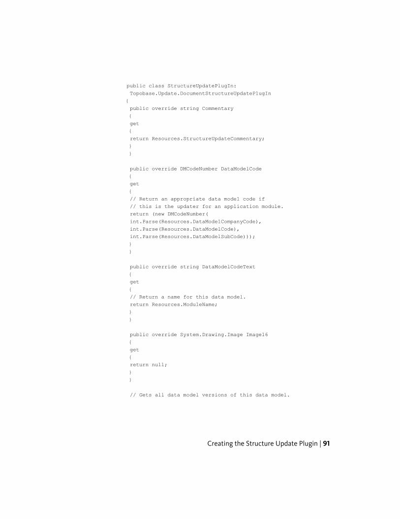
public class StructureUpdatePlugIn:
Topobase.Update.DocumentStructureUpdatePlugIn
{
public override string Commentary
{
get
{
return Resources.StructureUpdateCommentary;
}
}
public override DMCodeNumber DataModelCode
{
get
{
// Return an appropriate data model code if
// this is the updater for an application module.
return (new DMCodeNumber(
int.Parse(Resources.DataModelCompanyCode),
int.Parse(Resources.DataModelCode),
int.Parse(Resources.DataModelSubCode)));
}
}
public override string DataModelCodeText
{
get
{
// Return a name for this data model.
return Resources.ModuleName;
}
}
public override System.Drawing.Image Image16
{
get
{
return null;
}
}
// Gets all data model versions of this data model.
Creating the Structure Update Plugin | 91
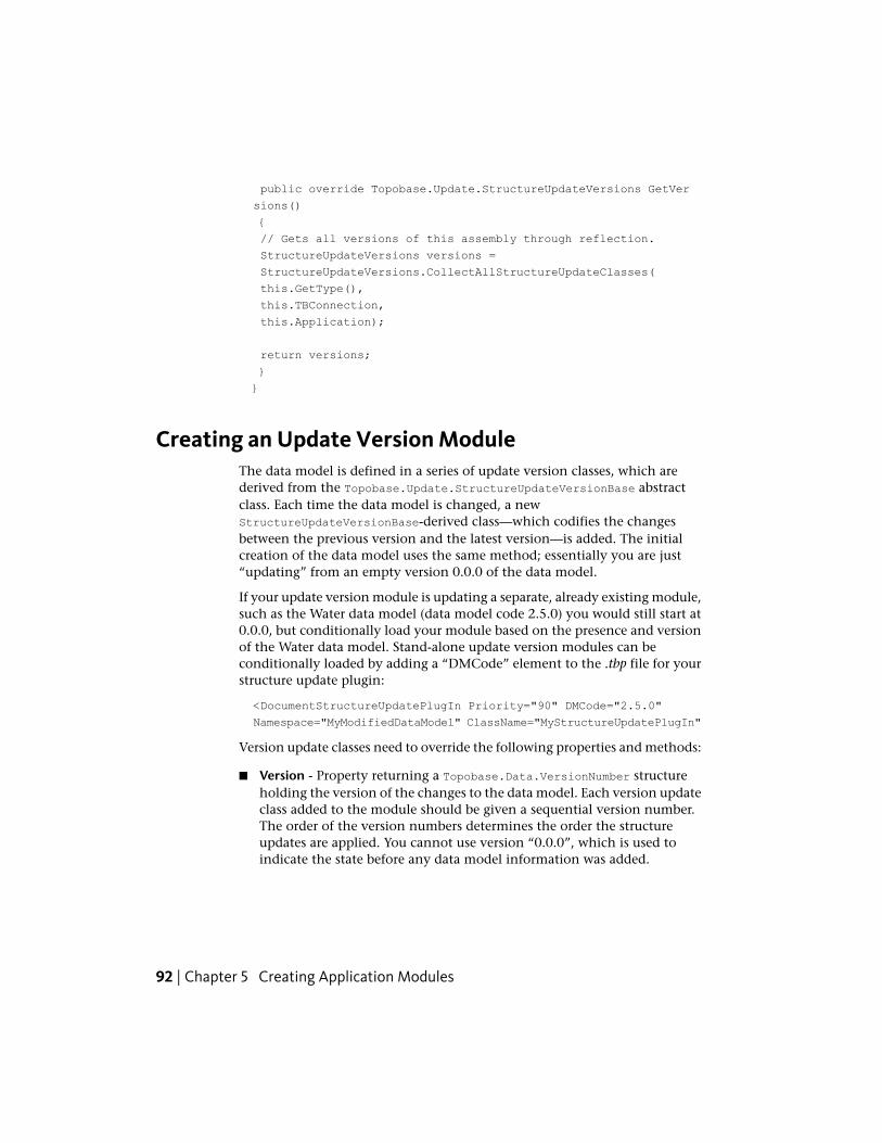
public override Topobase.Update.StructureUpdateVersions GetVer
sions()
{
// Gets all versions of this assembly through reflection.
StructureUpdateVersions versions =
StructureUpdateVersions.CollectAllStructureUpdateClasses(
this.GetType(),
this.TBConnection,
this.Application);
return versions;
}
}
Creating an Update Version ModuleThe data model is defined in a series of update version classes, which arederived from the Topobase.Update.StructureUpdateVersionBase abstractclass. Each time the data model is changed, a newStructureUpdateVersionBase-derived class—which codifies the changesbetween the previous version and the latest version—is added. The initialcreation of the data model uses the same method; essentially you are just“updating” from an empty version 0.0.0 of the data model.
If your update version module is updating a separate, already existing module,such as the Water data model (data model code 2.5.0) you would still start at0.0.0, but conditionally load your module based on the presence and versionof the Water data model. Stand-alone update version modules can beconditionally loaded by adding a “DMCode” element to the .tbp file for yourstructure update plugin:
<DocumentStructureUpdatePlugIn Priority="90" DMCode="2.5.0"
Namespace="MyModifiedDataModel" ClassName="MyStructureUpdatePlugIn"
Version update classes need to override the following properties and methods:
■ Version - Property returning a Topobase.Data.VersionNumber structureholding the version of the changes to the data model. Each version updateclass added to the module should be given a sequential version number.The order of the version numbers determines the order the structureupdates are applied. You cannot use version “0.0.0”, which is used toindicate the state before any data model information was added.
92 | Chapter 5 Creating Application Modules
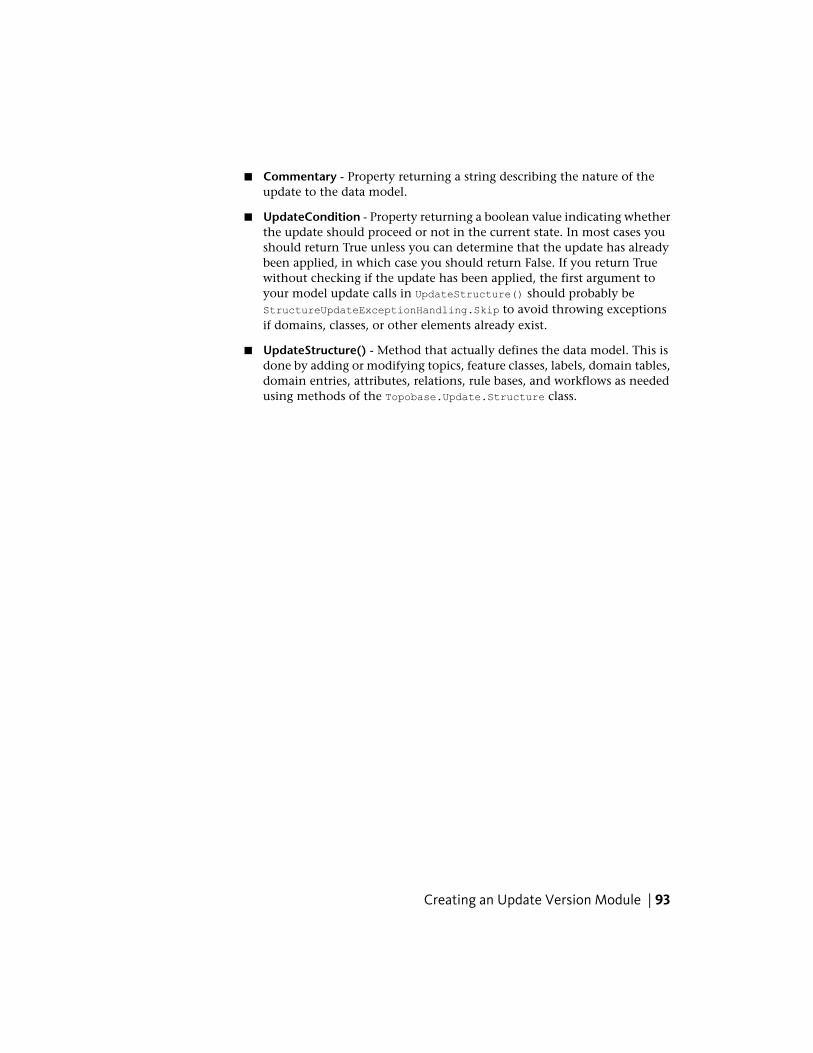
■ Commentary - Property returning a string describing the nature of theupdate to the data model.
■ UpdateCondition - Property returning a boolean value indicating whetherthe update should proceed or not in the current state. In most cases youshould return True unless you can determine that the update has alreadybeen applied, in which case you should return False. If you return Truewithout checking if the update has been applied, the first argument toyour model update calls in UpdateStructure() should probably beStructureUpdateExceptionHandling.Skip to avoid throwing exceptionsif domains, classes, or other elements already exist.
■ UpdateStructure() - Method that actually defines the data model. This isdone by adding or modifying topics, feature classes, labels, domain tables,domain entries, attributes, relations, rule bases, and workflows as neededusing methods of the Topobase.Update.Structure class.
Creating an Update Version Module | 93

The following is an example of an update version module that creates a datamodel consisting of two topics and two feature classes:
94 | Chapter 5 Creating Application Modules
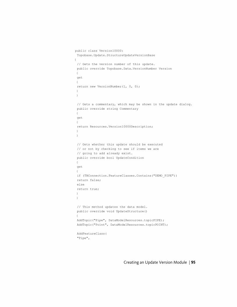
public class Version10000:
Topobase.Update.StructureUpdateVersionBase
{
// Gets the version number of this update.
public override Topobase.Data.VersionNumber Version
{
get
{
return new VersionNumber(1, 0, 0);
}
}
// Gets a commentary, which may be shown in the update dialog.
public override string Commentary
{
get
{
return Resources.Version10000Description;
}
}
// Gets whether this update should be executed
// or not by checking to see if items we are
// going to add already exist.
public override bool UpdateCondition
{
get
{
if (TBConnection.FeatureClasses.Contains("DEMO_PIPE"))
return false;
else
return true;
}
}
// This method updates the data model.
public override void UpdateStructure()
{
AddTopic("Pipe", DataModelResources.topicPIPE);
AddTopic("Point", DataModelResources.topicPOINT);
AddFeatureClass(
"Pipe",
Creating an Update Version Module | 95
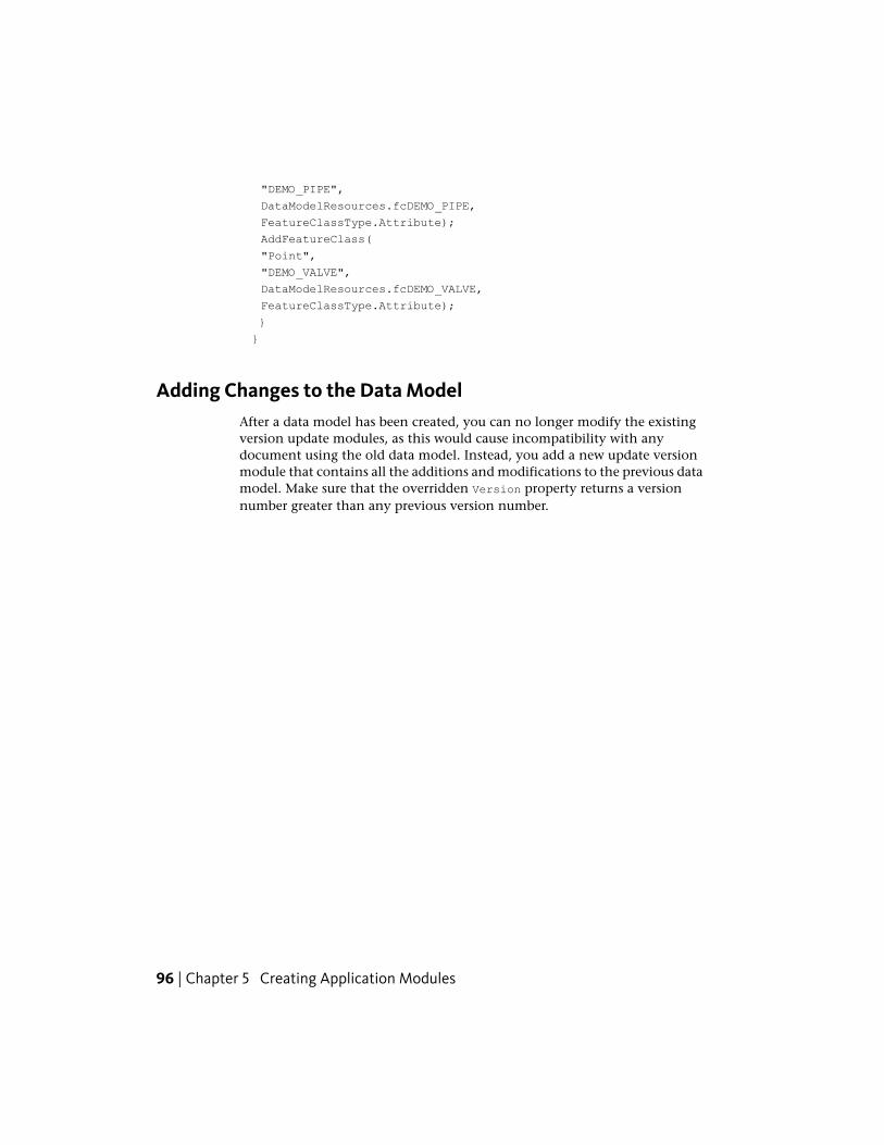
"DEMO_PIPE",
DataModelResources.fcDEMO_PIPE,
FeatureClassType.Attribute);
AddFeatureClass(
"Point",
"DEMO_VALVE",
DataModelResources.fcDEMO_VALVE,
FeatureClassType.Attribute);
}
}
Adding Changes to the Data ModelAfter a data model has been created, you can no longer modify the existingversion update modules, as this would cause incompatibility with anydocument using the old data model. Instead, you add a new update versionmodule that contains all the additions and modifications to the previous datamodel. Make sure that the overridden Version property returns a versionnumber greater than any previous version number.
96 | Chapter 5 Creating Application Modules

The following is an example of a version update module that adds twoattributes to the DEMO_PIPE feature class created in the Version10000 class:
Creating an Update Version Module | 97
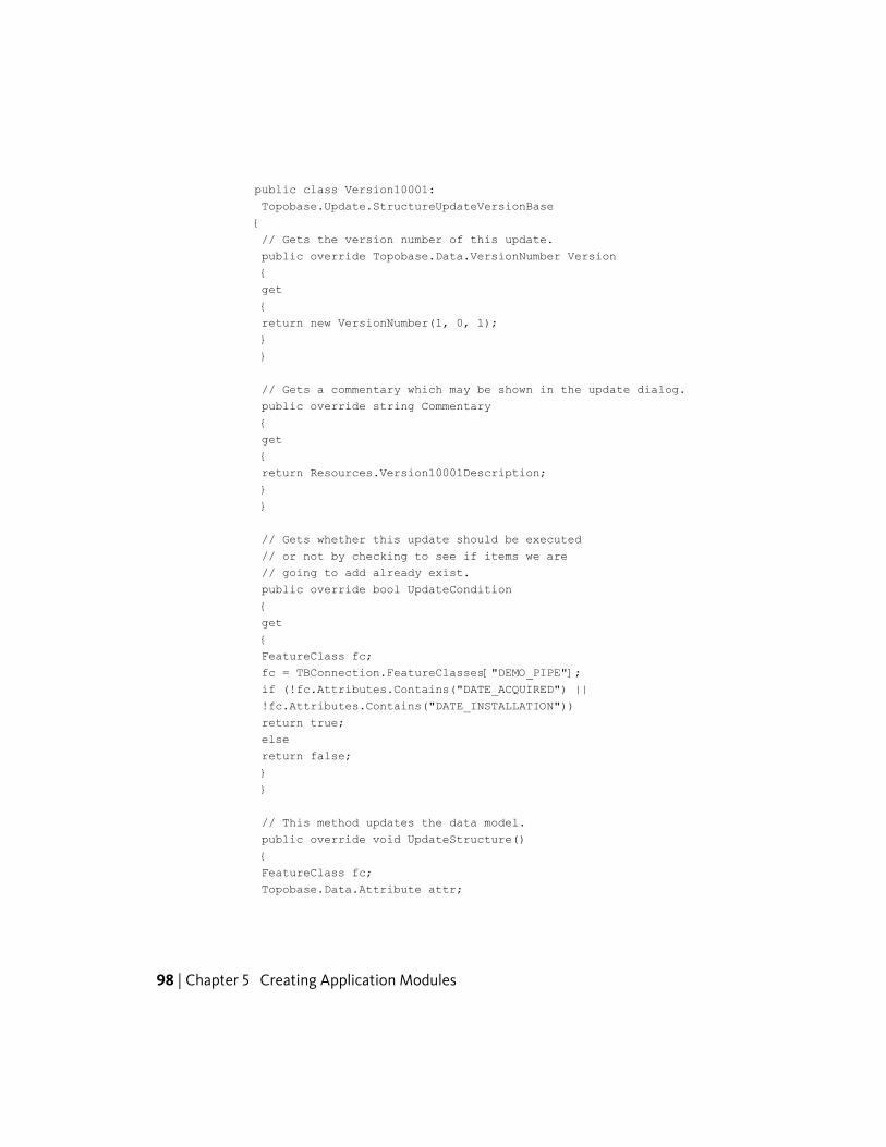
public class Version10001:
Topobase.Update.StructureUpdateVersionBase
{
// Gets the version number of this update.
public override Topobase.Data.VersionNumber Version
{
get
{
return new VersionNumber(1, 0, 1);
}
}
// Gets a commentary which may be shown in the update dialog.
public override string Commentary
{
get
{
return Resources.Version10001Description;
}
}
// Gets whether this update should be executed
// or not by checking to see if items we are
// going to add already exist.
public override bool UpdateCondition
{
get
{
FeatureClass fc;
fc = TBConnection.FeatureClasses["DEMO_PIPE"];
if (!fc.Attributes.Contains("DATE_ACQUIRED") ||
!fc.Attributes.Contains("DATE_INSTALLATION"))
return true;
else
return false;
}
}
// This method updates the data model.
public override void UpdateStructure()
{
FeatureClass fc;
Topobase.Data.Attribute attr;
98 | Chapter 5 Creating Application Modules
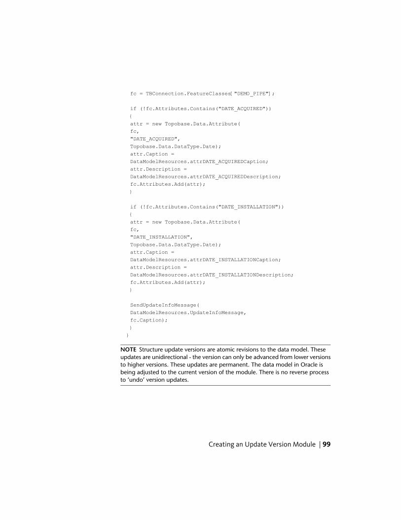
fc = TBConnection.FeatureClasses["DEMO_PIPE"];
if (!fc.Attributes.Contains("DATE_ACQUIRED"))
{
attr = new Topobase.Data.Attribute(
fc,
"DATE_ACQUIRED",
Topobase.Data.DataType.Date);
attr.Caption =
DataModelResources.attrDATE_ACQUIREDCaption;
attr.Description =
DataModelResources.attrDATE_ACQUIREDDescription;
fc.Attributes.Add(attr);
}
if (!fc.Attributes.Contains("DATE_INSTALLATION"))
{
attr = new Topobase.Data.Attribute(
fc,
"DATE_INSTALLATION",
Topobase.Data.DataType.Date);
attr.Caption =
DataModelResources.attrDATE_INSTALLATIONCaption;
attr.Description =
DataModelResources.attrDATE_INSTALLATIONDescription;
fc.Attributes.Add(attr);
}
SendUpdateInfoMessage(
DataModelResources.UpdateInfoMessage,
fc.Caption);
}
}
NOTE Structure update versions are atomic revisions to the data model. Theseupdates are unidirectional - the version can only be advanced from lower versionsto higher versions. These updates are permanent. The data model in Oracle isbeing adjusted to the current version of the module. There is no reverse processto ‘undo’ version updates.
Creating an Update Version Module | 99
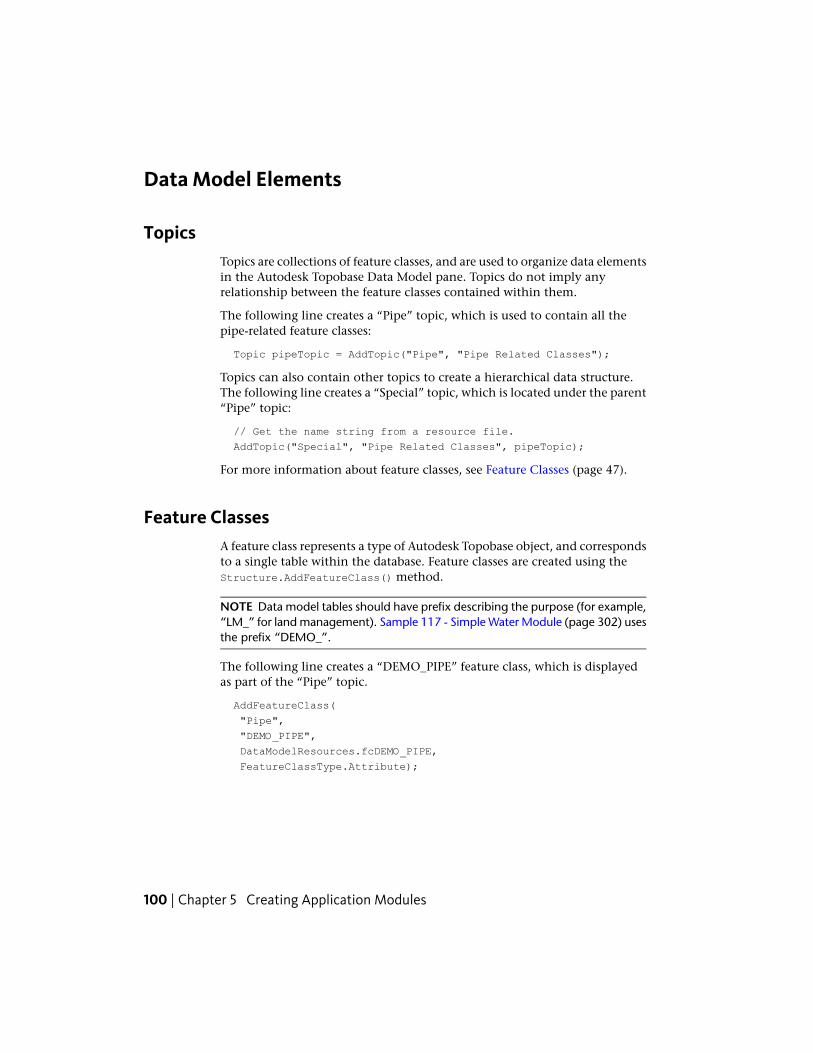
Data Model Elements
TopicsTopics are collections of feature classes, and are used to organize data elementsin the Autodesk Topobase Data Model pane. Topics do not imply anyrelationship between the feature classes contained within them.
The following line creates a “Pipe” topic, which is used to contain all thepipe-related feature classes:
Topic pipeTopic = AddTopic("Pipe", "Pipe Related Classes");
Topics can also contain other topics to create a hierarchical data structure.The following line creates a “Special” topic, which is located under the parent“Pipe” topic:
// Get the name string from a resource file.
AddTopic("Special", "Pipe Related Classes", pipeTopic);
For more information about feature classes, see Feature Classes (page 47).
Feature ClassesA feature class represents a type of Autodesk Topobase object, and correspondsto a single table within the database. Feature classes are created using theStructure.AddFeatureClass() method.
NOTE Data model tables should have prefix describing the purpose (for example,“LM_” for land management). Sample 117 - Simple Water Module (page 302) usesthe prefix “DEMO_”.
The following line creates a “DEMO_PIPE” feature class, which is displayedas part of the “Pipe” topic.
AddFeatureClass(
"Pipe",
"DEMO_PIPE",
DataModelResources.fcDEMO_PIPE,
FeatureClassType.Attribute);
100 | Chapter 5 Creating Application Modules
LabelsLabels are a kind of feature classthat is attached to a parent feature class, whichdisplays a text string at a specified point. Labels are created with theStructure.AddLabelFeatureClass() method.
NOTE Label feature classes automatically have suffix “_TBL” attached to them.
The following line adds a label feature class named “DEMO_PIPE_TBL” to the“DEMO_PIPE” feature class:
AddLabelFeatureClass(
"DEMO_PIPE",
"DEMO_PIPE_TBL",
DataModelResources.lblFcDEMO_PIPE_TBL);
AttributesEach feature class type contains a set of predefined attributes (that is, columnsin the database table). User-defined attributes can also be added to featureclasses. Attributes are added or modified using the Attributes collection ina feature class object.
The following code first gets a reference to the “DEMO_PIPE” feature class. Itthen checks to make sure the attribute has not already been added. If it has
Data Model Elements | 101
not, then it creates a new attribute named “PIPE_LENGTH”, a numeric value,and then adds it to the feature class:
FeatureClass fc;
Topobase.Data.Attribute attr;
fc = TBConnection.FeatureClasses["DEMO_PIPE"];
if (fc == null)
return;
if (!fc.Attributes.Contains("PIPE_LENGTH"))
{
attr = new Topobase.Data.Attribute(
fc,
"PIPE_LENGTH",
Topobase.Data.DataType.Number);
attr.Precision = 20;
attr.Scale = 8;
attr.UnitID = TBConnection.GetUnit(MeasuringUnitType.Length);
attr.Caption = DataModelResources.attrPIPE_LENGTHCaption;
attr.Description = DataModelResources.attrPIPE_LENGTHDesc;
fc.Attributes.Add(attr);
}
Attribute RelationsAn attribute relation defines a relationship between attributes in differenttables. It can define the association cardinality between attributes and/or anaction to take with the child attribute when something happens to the parentattribute. Attribute relations are set using theStructureAddAttributeRelation() method.
The following line creates a relation between the parent “FID” attribute of theDEMO_PIPE feature class and the child “FID_FEATURE” of theDEMO_MAINTENANCE feature class. When a feature of type Pipe is deleted,the maintenance features associated to it are deleted as well.
AddAttributeRelation(
"DEMO_MAINTENANCE",
"FID_FEATURE",
"DEMO_PIPE",
"FID",
RelationType.DeleteChild);
102 | Chapter 5 Creating Application Modules
Domains
Domains
User-defined attributes can be created using common data types, such asnumbers or strings. They can also be limited to a specified enumeration ofvalues. A list of possible values such an attribute can have is called a “domain.”Each domain corresponds to a single table in the database. Domains are createdusing the Structure.AddDomainTable() method.
NOTE Domain tables automatically have suffix “_TBD” attached to them.
The following line creates a “DEMO_MAINTENANCE_TYPE_TBD” domain:
AddDomainTable(
"DEMO_MAINTENANCE_TYPE_TBD",
"DEMO MAINTENANCE TYPE");
Domain Values
Values within a domain are added individually. The following code adds threenew values to the DEMO_MAINTAINENANCE_TYPE_TBD domain: “u”, “o”,and “tbd”:
AddDomainEntry("DEMO_MAINTENANCE_TYPE_TBD",
1,
"unknown",
"u",
"description",
true);
AddDomainEntry("DEMO_MAINTENANCE_TYPE_TBD",
10000,
"other",
"o",
"description"
true);
AddDomainEntry("DEMO_MAINTENANCE_TYPE_TBD",
10001,
"to be determined",
"tbd",
"description"
true);
Data Model Elements | 103
Domain Relations
A domain relationship is used to set a particular attribute to use the defineddomain. The following line sets the ID_MAINTENANCE_TYPE attribute of theDEMO_MAINTENANCE feature class to use theDEMO_MAINTENANCE_TYPE_TBD domain:
AddRelationToDomain(
"DEMO_MAINTENANCE_TYPE_TBD",
"DEMO_MAINTENANCE",
"ID_MAINTENANCE_TYPE");
Now an ID_MAINTENANCE_TYPE attribute can hold one of three values: “u”,“o”, or “tbd”.
Utility ModelA utility model is a system of organizing feature classes for utility networks.It contains the relationship between the geometry and the attribute featureclasses and adds network geometry.
The following code creates a utility model where the feature classesDEMO_VALVE and DEMO_HYDRANT can be used as nodes in the networkand the feature class DEMO_PIPE is used for the connecting lines:
// Make an array of all the feature class names that act
// as nodes.
string[] attrPoints = new string[]
{ "DEMO_VALVE", "DEMO_HYDRANT" };
// Make an array of all the feature class names that act
// as lines.
string[] attrLines = new string[] { "DEMO_PIPE" };
CreateUtility("DEMO", "DEMO_LINE", attrLines, "DEMO_POINT",
attrPoints, 0.01d, "DEMO", true);
Client-Side Feature RulesAnother aspect of the data model is the client-side feature rule. Feature rulesdefine the business rules of the data model, performing consistency checks,dependency checks, data correction, and many other tasks. A number offeature rules are predefined in Autodesk Topobase, but you can create moreas needed. Rules are stored in the TB_RULE_DEF table.
104 | Chapter 5 Creating Application Modules
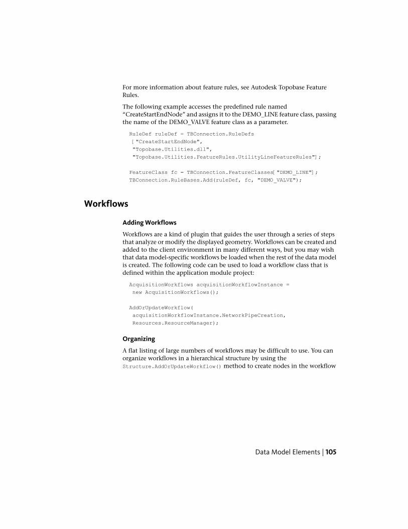
For more information about feature rules, see Autodesk Topobase FeatureRules.
The following example accesses the predefined rule named“CreateStartEndNode” and assigns it to the DEMO_LINE feature class, passingthe name of the DEMO_VALVE feature class as a parameter.
RuleDef ruleDef = TBConnection.RuleDefs
["CreateStartEndNode",
"Topobase.Utilities.dll",
"Topobase.Utilities.FeatureRules.UtilityLineFeatureRules"];
FeatureClass fc = TBConnection.FeatureClasses["DEMO_LINE"];
TBConnection.RuleBases.Add(ruleDef, fc, "DEMO_VALVE");
Workflows
Adding Workflows
Workflows are a kind of plugin that guides the user through a series of stepsthat analyze or modify the displayed geometry. Workflows can be created andadded to the client environment in many different ways, but you may wishthat data model-specific workflows be loaded when the rest of the data modelis created. The following code can be used to load a workflow class that isdefined within the application module project:
AcquisitionWorkflows acquisitionWorkflowInstance =
new AcquisitionWorkflows();
AddOrUpdateWorkflow(
acquisitionWorkflowInstance.NetworkPipeCreation,
Resources.ResourceManager);
Organizing
A flat listing of large numbers of workflows may be difficult to use. You canorganize workflows in a hierarchical structure by using theStructure.AddOrUpdateWorkflow() method to create nodes in the workflow
Data Model Elements | 105
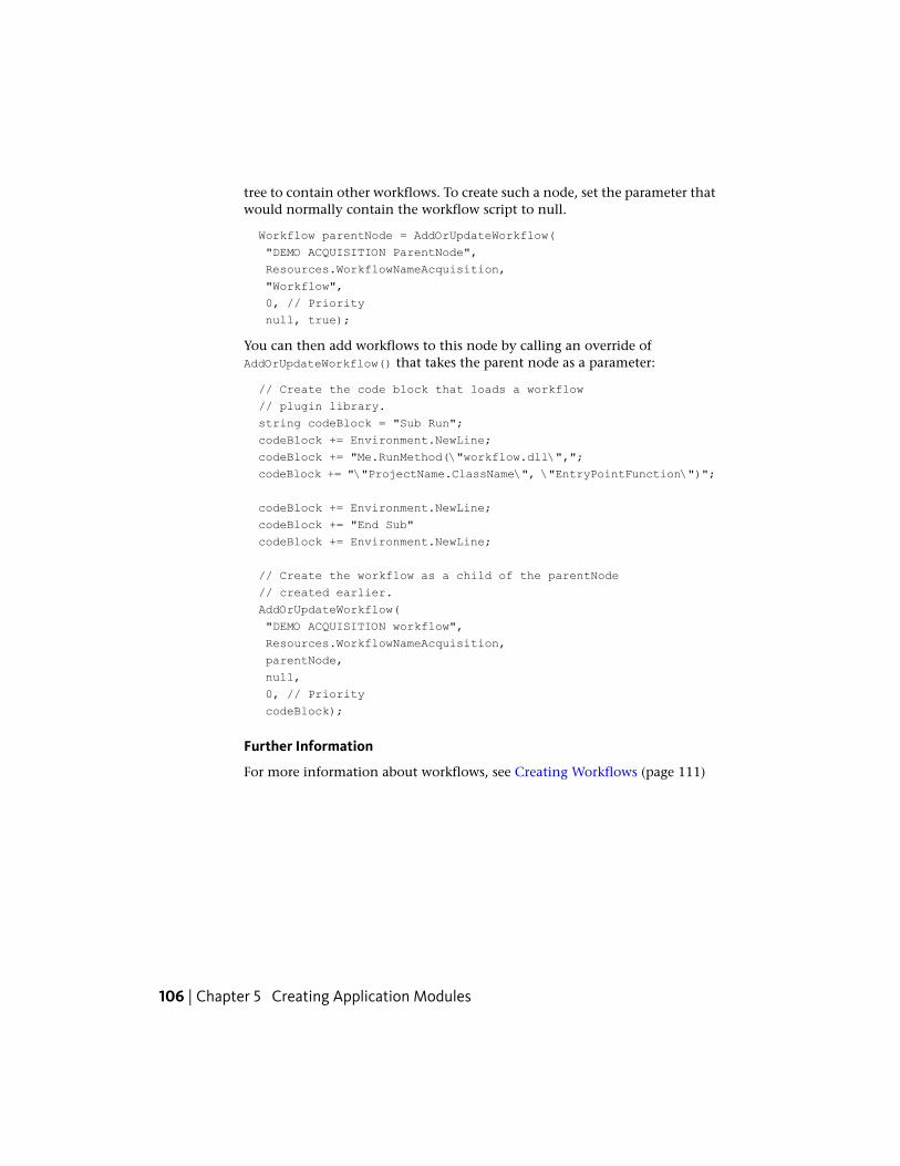
tree to contain other workflows. To create such a node, set the parameter thatwould normally contain the workflow script to null.
Workflow parentNode = AddOrUpdateWorkflow(
"DEMO ACQUISITION ParentNode",
Resources.WorkflowNameAcquisition,
"Workflow",
0, // Priority
null, true);
You can then add workflows to this node by calling an override ofAddOrUpdateWorkflow() that takes the parent node as a parameter:
// Create the code block that loads a workflow
// plugin library.
string codeBlock = "Sub Run";
codeBlock += Environment.NewLine;
codeBlock += "Me.RunMethod(\"workflow.dll\",";
codeBlock += "\"ProjectName.ClassName\", \"EntryPointFunction\")";
codeBlock += Environment.NewLine;
codeBlock += "End Sub"
codeBlock += Environment.NewLine;
// Create the workflow as a child of the parentNode
// created earlier.
AddOrUpdateWorkflow(
"DEMO ACQUISITION workflow",
Resources.WorkflowNameAcquisition,
parentNode,
null,
0, // Priority
codeBlock);
Further Information
For more information about workflows, see Creating Workflows (page 111)
106 | Chapter 5 Creating Application Modules
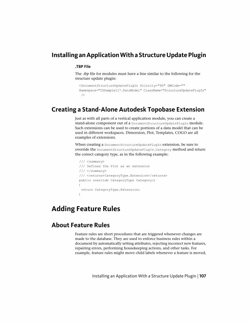
Installing an Application With a Structure Update Plugin
.TBP File
The .tbp file for modules must have a line similar to the following for thestructure update plugin:
<DocumentStructureUpdatePlugIn Priority="90" DMCode=""
Namespace="CSSample117.DataModel" ClassName="StructureUpdatePlugIn"
/>
Creating a Stand-Alone Autodesk Topobase ExtensionJust as with all parts of a vertical application module, you can create astand-alone component out of a DocumentStructureUpdatePlugIn module.Such extensions can be used to create portions of a data model that can beused in different workspaces. Dimension, Plot, Templates, COGO are allexamples of extensions.
When creating a DocumentStructureUpdatePlugIn extension, be sure tooverride the DocumentStructureUpdatePlugIn.Category method and returnthe correct category type, as in the following example:
/// <summary>
/// Defines the Plot as an extension
/// </summary>
/// <returns>CategoryType.Extension</returns>
public override CategoryType Category()
{
return CategoryType.Extension;
}
Adding Feature Rules
About Feature RulesFeature rules are short procedures that are triggered whenever changes aremade to the database. They are used to enforce business rules within adocument by automatically setting attributes, rejecting incorrect new features,repairing errors, performing housekeeping actions, and other tasks. Forexample, feature rules might move child labels whenever a feature is moved,
Installing an Application With a Structure Update Plugin | 107
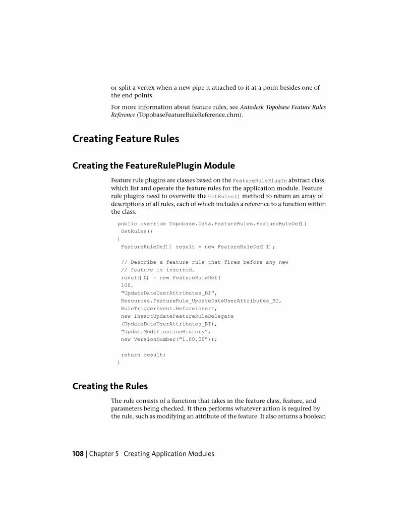
or split a vertex when a new pipe it attached to it at a point besides one ofthe end points.
For more information about feature rules, see Autodesk Topobase Feature RulesReference (TopobaseFeatureRuleReference.chm).
Creating Feature Rules
Creating the FeatureRulePlugin ModuleFeature rule plugins are classes based on the FeatureRulePlugIn abstract class,which list and operate the feature rules for the application module. Featurerule plugins need to overwrite the GetRules() method to return an array ofdescriptions of all rules, each of which includes a reference to a function withinthe class.
public override Topobase.Data.FeatureRules.FeatureRuleDef[]
GetRules()
{
FeatureRuleDef[] result = new FeatureRuleDef[1];
// Describe a feature rule that fires before any new
// feature is inserted.
result[0] = new FeatureRuleDef(
100,
"UpdateDateUserAttributes_BI",
Resources.FeatureRule_UpdateDateUserAttributes_BI,
RuleTriggerEvent.BeforeInsert,
new InsertUpdateFeatureRuleDelegate
(UpdateDateUserAttributes_BI),
"UpdateModificationHistory",
new VersionNumber("1.00.00"));
return result;
}
Creating the RulesThe rule consists of a function that takes in the feature class, feature, andparameters being checked. It then performs whatever action is required bythe rule, such as modifying an attribute of the feature. It also returns a boolean
108 | Chapter 5 Creating Application Modules
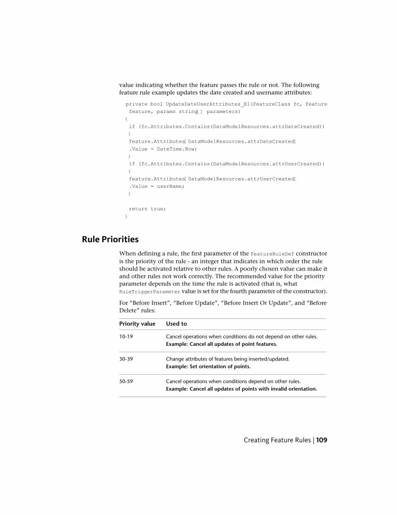
value indicating whether the feature passes the rule or not. The followingfeature rule example updates the date created and username attributes:
private bool UpdateDateUserAttributes_BI(FeatureClass fc, Feature
feature, params string[] parameters)
{
if (fc.Attributes.Contains(DataModelResources.attrDateCreated))
{
feature.Attributes[DataModelResources.attrDateCreated]
.Value = DateTime.Now;
}
if (fc.Attributes.Contains(DataModelResources.attrUserCreated))
{
feature.Attributes[DataModelResources.attrUserCreated]
.Value = userName;
}
return true;
}
Rule PrioritiesWhen defining a rule, the first parameter of the FeatureRuleDef constructoris the priority of the rule - an integer that indicates in which order the ruleshould be activated relative to other rules. A poorly chosen value can make itand other rules not work correctly. The recommended value for the priorityparameter depends on the time the rule is activated (that is, whatRuleTriggerParameter value is set for the fourth parameter of the constructor).
For “Before Insert”, “Before Update”, “Before Insert Or Update”, and “BeforeDelete” rules:
Used toPriority value
Cancel operations when conditions do not depend on other rules.Example: Cancel all updates of point features.
10-19
Change attributes of features being inserted/updated.Example: Set orientation of points.
30-39
Cancel operations when conditions depend on other rules.Example: Cancel all updates of points with invalid orientation.
50-59
Creating Feature Rules | 109
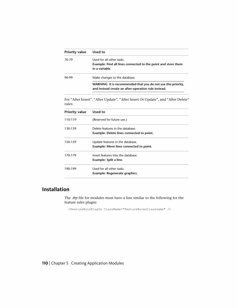
Used toPriority value
Used for all other tasks.Example: Find all lines connected to the point and store themin a variable.
70-79
Make changes to the database.
WARNING It is recommended that you do not use this priority,and instead create an after-operation rule instead.
90-99
For “After Insert”, “After Update”, “After Insert Or Update”, and “After Delete”rules:
Used toPriority value
(Reserved for future use.)110-119
Delete features in the database.Example: Delete lines connected to point.
130-139
Update features in the database.Example: Move lines connected to point.
150-159
Insert features into the database.Example: Split a line.
170-179
Used for all other tasks.Example: Regenerate graphics.
190-199
InstallationThe .tbp file for modules must have a line similar to the following for thefeature rules plugin:
<FeatureRulePlugIn ClassName="FeatureRulesClassname" />
110 | Chapter 5 Creating Application Modules
Creating Workflows
About WorkflowsA workflow is a program that guides the user through a complicated task.When a workflow is started, the user is presented with a user interface prompt,such as a message box or controls in the Autodesk Topobase task pane,directing them through a series of steps such as setting workflow parameters,selecting features for analysis, or digitizing new features. There are two waysto create a workflow program: writing Visual Basic script in Autodesk TopobaseAdministrator, or by creating a workflow plugin using Visual Studio .NET.
Workflow Scripts in Autodesk Topobase AdministratorThe Autodesk Topobase Administrator includes a tab for creating newworkflows within a workspace document. A textbox allows the user to typein the workflow code in the Visual Basic .NET language.
To create a new blank workflow:
1 Launch the Autodesk Topobase Administrator and load the workspace.
2 In the tree view, under the document to which you want to add theworkflow, click Workflows.
3 In the Workflow Administrator page, click the parent workflow in thetree view and click Create.
4 Type the name of the new workflow.
A new entry for the workflow and a simple template for adding yourworkflow code is displayed. Adjust the name, display name, and icon asneeded.
5 When you are done creating the workflow, click Save.
The entry point for a workflow script is the Run subroutine. You can createother subroutines and functions, but a script must contain at least the Runsubroutine.
Creating Workflows | 111
NOTE There are a number of limitations when working with workflow scripts. Thecode window is limited in size, and the script interpreter provides only the mostbasic of features. There are no debugging features. You can only access a subsetof the Visual Basic .NET language. Because of these issues, workflow scripts areonly useful for simple workflows.
The following is a sample workflow script. It prompts the user for a name fora new valve, has the user digitize a new WA_VALVE feature, and sets the nameof the feature to the string the user gave earlier. It then opens the featuredialog box to allow the user to type in new attribute values.
Sub Run
Dim name As String
name = InputBox("Input name of new valve:", "Digitize Valve")
If (not string.IsNullOrEmpty(name)) Then
me.Digitize("WA_VALVE")
' "0" is that always the latest item that was digitized
me.Features.List.Item(0).Attributes.Item("NAME_NUMBER").Value =
name
me.Features.Update()
me.OpenDialog()
End If
End Sub
Use of the “Me” ObjectWorkflow scripts are derived from the Topobase.Workflows.ScriptClassabstract class. By using the Me object in the script, you can gain access to themany base objects and useful functions provided by ScriptClass.
The following are the objects provided by the Me object. With these you canaccess all of the main features of the Autodesk Topobase environment anddocument data:
■ Application - This object contains information about the current workingenvironment, the current user, and the open workspace and documents.It is a reference to the base application object derived from theTopobase.Forms.Application abstract class.
■ Document - This objects allows you to interact with the document thatthis workflow is part of, including displaying dialog boxes or closing thedocument. It is a reference to one of the documents in the current
112 | Chapter 5 Creating Application Modules
workspace, an object derived from the Topobase.Forms.Document abstractclass.
■ Features - This object provides methods for accessing and modifying thelist of features that were just recently digitized. It is an instance of theTopobase.Workflows.Features class.The following is an example using the Me object:
' Digitize a new pipe and then display a message box with
' the feature ID of the newly created feature.
Me.Digitize("DEMO_PIPE")
Me.MessageBox(Me.Features.ListItem(0).Attrib
utes.Item("FID").Value)
The following are some of the useful methods provided by the Me object:
■ ShowMessage() - Hides any explorer currently displayed in the AutodeskTopobase task pane and displays a string message inside. When theworkflow ends, the Autodesk Topobase task pane reverts to its previousstate.
■ MessageBox() - Displays a standard message box with a single “Ok” buttonand a single string message with an optional title. Processing of theworkflow pauses until the message box is dismissed.
■ InputBox() - Displays a standard input box allowing the user to input astring value. Processing of the workflow pauses until the input box isdismissed.
■ Digitize() - Allows the user to add features of the specified feature class tothe document.
■ RunMethod() - Runs a method from an external .dll library. The mostimportant use of RunMethod is to launch workflow plugins.
Workflow PluginA workflow plugin is a class library created in Visual Studio .NET. It mustcontain a class based on Workflows.WorkflowPlugIn, but otherwise you havefreedom in creating its design.
Workflow Plugin | 113
Create a Workflow Plugin ModuleWorkflow plugins are classes derived from the Workflows.WorkflowPlugInabstract parent class.
class AcquisitionWorkflows : Topobase.Workflows.WorkflowPlugIn
{
}
Creating the Entry Point
Workflows are accessed by an entry point - a public function with noparameters and no return value. You can use any function name. Instead ofparameters, the instance of the WorkflowPlugIn-derived class has manyproperties and methods for getting information about the current documentand the state of the environment. That instance can be accessed using thethis keyword in C# or Me keyword in Visual Basic .NET.
Generally, the entry point should perform three actions. First, check if thecurrent state of Autodesk Topobase and of the document allows the workflowto work correctly. Second, request input from the user, and third, update thedatabase based on the user’s input.
The following sample entry point demonstrates a particular kind of workflow,which creates an interface in the workflow pane. This entry point checks thecurrent state of Autodesk Topobase, creates the user interface elements forinitializing the workflow into the workflow pane, and then adds an event tothe user interface elements to start the interactive part of the workflow when
114 | Chapter 5 Creating Application Modules

the initialization phase is complete. The CreateNetworkPipe_Closed eventcontains the code for updating the database.
Workflow Plugin | 115
public void NetworkPipeCreation()
{
// Determine if Topobase is in the correct state for the
// workflow to be meaningful.
// Check if the utility is loaded.
if (this.Utility == null)
return;
// Also check if the map is connected to the document.
if (this.Document.Map.IsConnected(true))
return;
// Create the container in the workflow pane with Ok and
// Cancel buttons.
IWorkflowContainer container = WorkflowContainerFactory.Create(
this.WorkflowSupport,
ContainerButtons.OkCancel,
Resources.ModuleName,
false);
// Add a control to the container that asks if the user
// wants to set a reference for the features they are about
// to digitize.
FeatureClass fc = Document.Connection.
FeatureClasses["DEMO_PIPE"];
RefFeatureData refData = new RefFeatureData(
this.WorkflowSupport, "refData", fc,
string.Format(
CultureInfo.CurrentCulture,
Resources.ChooseReferenceOf,
fc.Caption)
);
IWorkflowUserControl refControl =
WorkflowUserControlFactory.Create(refData);
container.AddUserControl(refControl);
// Make the container visible.
this.WorkflowSupport.WorkflowExplorerFlyIn.
ShowWorkflowContainer(container);
// Add an event for when the user clicks the Ok or
116 | Chapter 5 Creating Application Modules
// Cancel buttons on the container.
container.Closed += new EventHandler(CreateNetworkPipe_Closed);
}
Create a Workflow Pane UIThe defining characteristic of a workflow is that it guides the user through aprocess by using user interface messages and controls. Autodesk Topobaseprovides many different systems of interacting with the user, depending onthe need of the workflow. You may only need the simplest message displays,or the full flexibility and options of a Windows user control, or thecompatibility between different versions of the Autodesk Topobase Client thatthe Autodesk Topobase controls can provide.
Displaying Simple Messages
Message Box
One way to provide messages to the user is to display a modal message box,which the user can dismiss and then continue with the workflow process.Message boxes can be displayed with the Application.MsgBox() method.
this.Application.MsgBox("Hello");
This is the simplest way to present a message to the user. TheApplication.MessageBox() method performs a similar task, but also gives youthe options of setting the message box title and using a mono-spaced font.
// Use a message of "Hello", a title of "Title", and the
// standard font.
this.Application.MessageBox("Hello", "Title", false);
ShowMessage
Another way to provide the user a message is to use theWorkflowSupport.WorkflowExplorerFlyIn.ShowMessage() method. This hidesany explorer in the Autodesk Topobase task pane and display a string centeredwithin that area. This message is modeless, so it continues to be displayed asthe user performs workflow tasks, such as digitizing features.
this.WorkflowSupport.WorkflowExplorerFlyIn.
ShowMessage("Start Digitizing. Press ESC when done.");
Workflow Plugin | 117
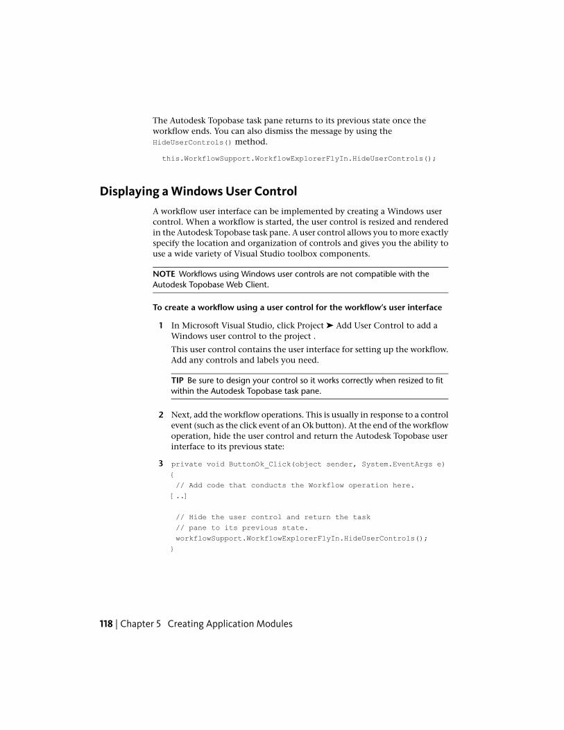
The Autodesk Topobase task pane returns to its previous state once theworkflow ends. You can also dismiss the message by using theHideUserControls() method.
this.WorkflowSupport.WorkflowExplorerFlyIn.HideUserControls();
Displaying a Windows User ControlA workflow user interface can be implemented by creating a Windows usercontrol. When a workflow is started, the user control is resized and renderedin the Autodesk Topobase task pane. A user control allows you to more exactlyspecify the location and organization of controls and gives you the ability touse a wide variety of Visual Studio toolbox components.
NOTE Workflows using Windows user controls are not compatible with theAutodesk Topobase Web Client.
To create a workflow using a user control for the workflow’s user interface
1 In Microsoft Visual Studio, click Project ➤ Add User Control to add aWindows user control to the project .
This user control contains the user interface for setting up the workflow.Add any controls and labels you need.
TIP Be sure to design your control so it works correctly when resized to fitwithin the Autodesk Topobase task pane.
2 Next, add the workflow operations. This is usually in response to a controlevent (such as the click event of an Ok button). At the end of the workflowoperation, hide the user control and return the Autodesk Topobase userinterface to its previous state:
3 private void ButtonOk_Click(object sender, System.EventArgs e)
{
// Add code that conducts the Workflow operation here.
[..]
// Hide the user control and return the task
// pane to its previous state.
workflowSupport.WorkflowExplorerFlyIn.HideUserControls();
}
118 | Chapter 5 Creating Application Modules
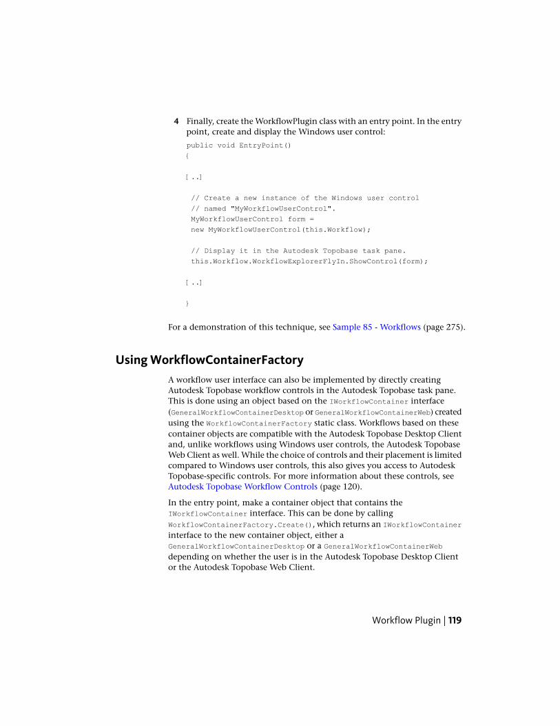
4 Finally, create the WorkflowPlugin class with an entry point. In the entrypoint, create and display the Windows user control:
public void EntryPoint()
{
[..]
// Create a new instance of the Windows user control
// named "MyWorkflowUserControl".
MyWorkflowUserControl form =
new MyWorkflowUserControl(this.Workflow);
// Display it in the Autodesk Topobase task pane.
this.Workflow.WorkflowExplorerFlyIn.ShowControl(form);
[..]
}
For a demonstration of this technique, see Sample 85 - Workflows (page 275).
Using WorkflowContainerFactoryA workflow user interface can also be implemented by directly creatingAutodesk Topobase workflow controls in the Autodesk Topobase task pane.This is done using an object based on the IWorkflowContainer interface(GeneralWorkflowContainerDesktop or GeneralWorkflowContainerWeb) createdusing the WorkflowContainerFactory static class. Workflows based on thesecontainer objects are compatible with the Autodesk Topobase Desktop Clientand, unlike workflows using Windows user controls, the Autodesk TopobaseWeb Client as well. While the choice of controls and their placement is limitedcompared to Windows user controls, this also gives you access to AutodeskTopobase-specific controls. For more information about these controls, seeAutodesk Topobase Workflow Controls (page 120).
In the entry point, make a container object that contains theIWorkflowContainer interface. This can be done by callingWorkflowContainerFactory.Create(), which returns an IWorkflowContainerinterface to the new container object, either aGeneralWorkflowContainerDesktop or a GeneralWorkflowContainerWebdepending on whether the user is in the Autodesk Topobase Desktop Clientor the Autodesk Topobase Web Client.
Workflow Plugin | 119
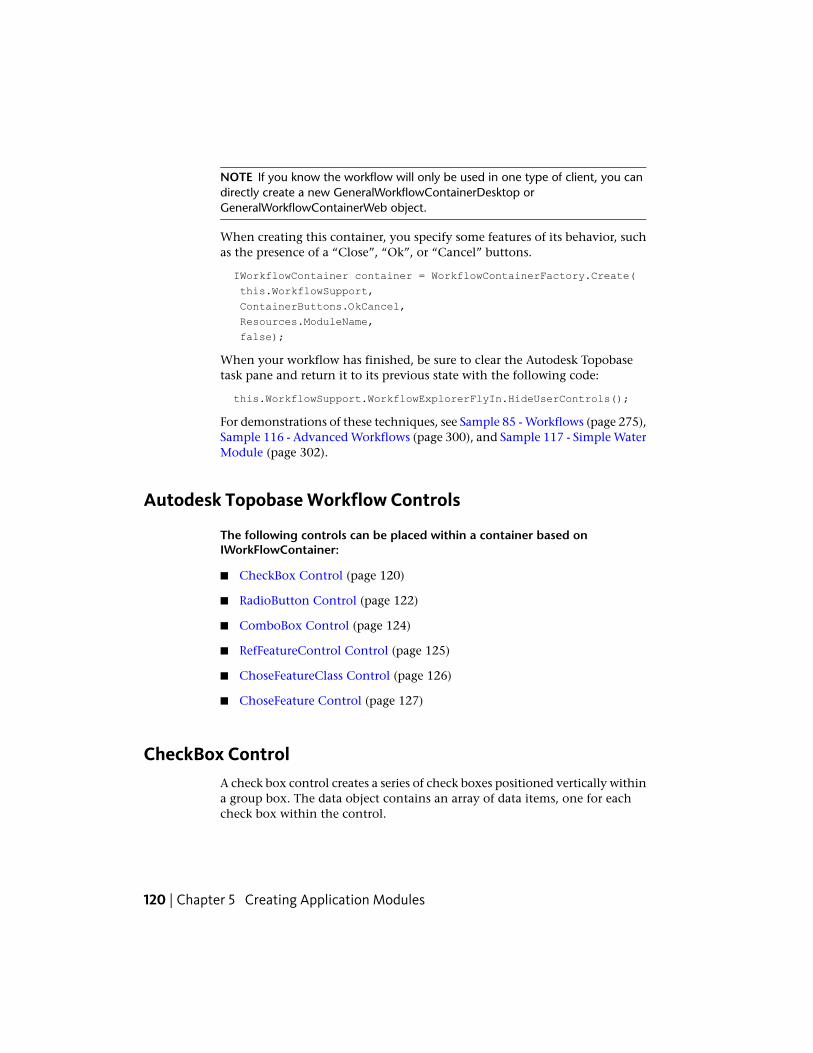
NOTE If you know the workflow will only be used in one type of client, you candirectly create a new GeneralWorkflowContainerDesktop orGeneralWorkflowContainerWeb object.
When creating this container, you specify some features of its behavior, suchas the presence of a “Close”, “Ok”, or “Cancel” buttons.
IWorkflowContainer container = WorkflowContainerFactory.Create(
this.WorkflowSupport,
ContainerButtons.OkCancel,
Resources.ModuleName,
false);
When your workflow has finished, be sure to clear the Autodesk Topobasetask pane and return it to its previous state with the following code:
this.WorkflowSupport.WorkflowExplorerFlyIn.HideUserControls();
For demonstrations of these techniques, see Sample 85 - Workflows (page 275),Sample 116 - Advanced Workflows (page 300), and Sample 117 - Simple WaterModule (page 302).
Autodesk Topobase Workflow Controls
The following controls can be placed within a container based onIWorkFlowContainer:
■ CheckBox Control (page 120)
■ RadioButton Control (page 122)
■ ComboBox Control (page 124)
■ RefFeatureControl Control (page 125)
■ ChoseFeatureClass Control (page 126)
■ ChoseFeature Control (page 127)
CheckBox ControlA check box control creates a series of check boxes positioned vertically withina group box. The data object contains an array of data items, one for eachcheck box within the control.
120 | Chapter 5 Creating Application Modules
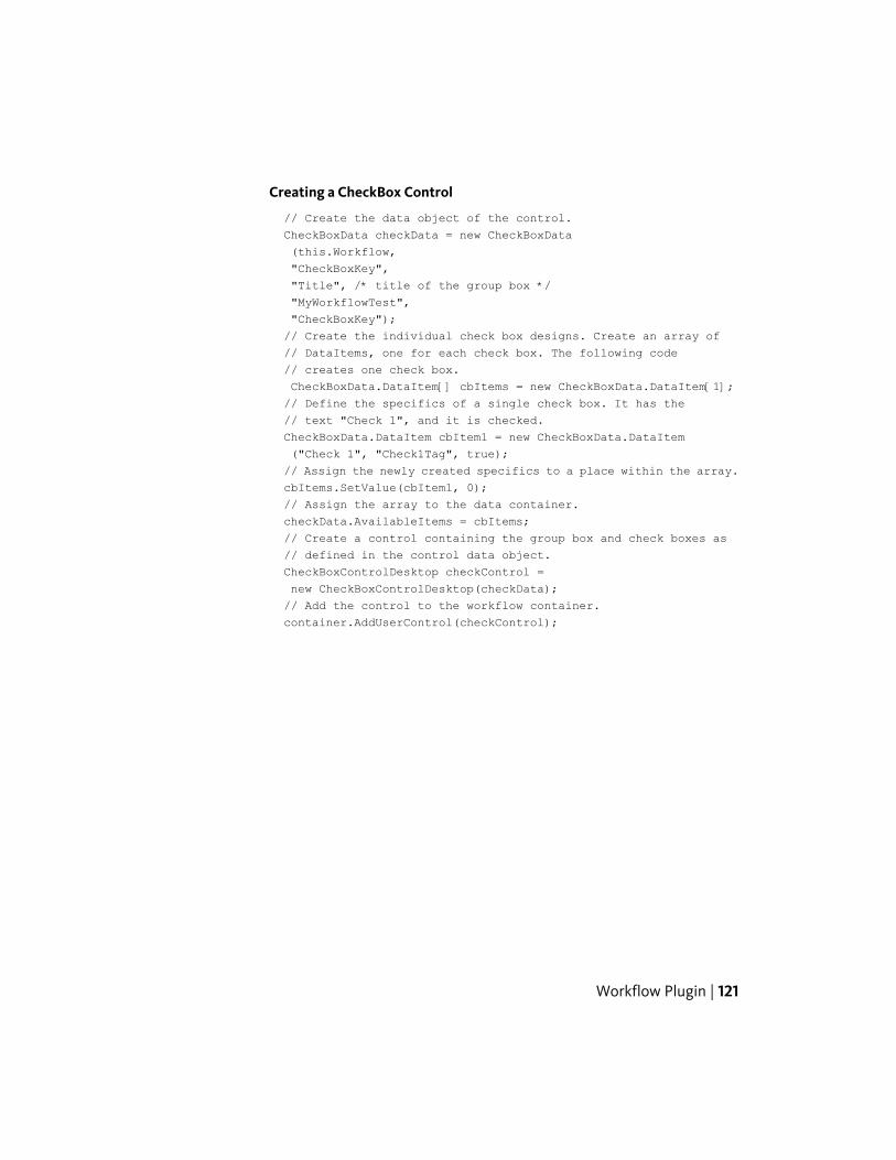
Creating a CheckBox Control
// Create the data object of the control.
CheckBoxData checkData = new CheckBoxData
(this.Workflow,
"CheckBoxKey",
"Title", /* title of the group box */
"MyWorkflowTest",
"CheckBoxKey");
// Create the individual check box designs. Create an array of
// DataItems, one for each check box. The following code
// creates one check box.
CheckBoxData.DataItem[] cbItems = new CheckBoxData.DataItem[1];
// Define the specifics of a single check box. It has the
// text "Check 1", and it is checked.
CheckBoxData.DataItem cbItem1 = new CheckBoxData.DataItem
("Check 1", "Check1Tag", true);
// Assign the newly created specifics to a place within the array.
cbItems.SetValue(cbItem1, 0);
// Assign the array to the data container.
checkData.AvailableItems = cbItems;
// Create a control containing the group box and check boxes as
// defined in the control data object.
CheckBoxControlDesktop checkControl =
new CheckBoxControlDesktop(checkData);
// Add the control to the workflow container.
container.AddUserControl(checkControl);
Workflow Plugin | 121
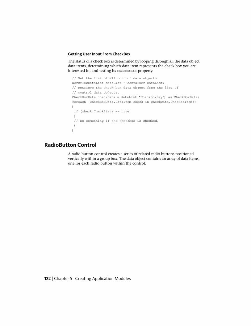
Getting User Input From CheckBox
The status of a check box is determined by looping through all the data objectdata items, determining which data item represents the check box you areinterested in, and testing its CheckState property.
// Get the list of all control data objects.
WorkflowDataList dataList = container.DataList;
// Retrieve the check box data object from the list of
// control data objects.
CheckBoxData checkData = dataList["CheckBoxKey"] as CheckBoxData;
foreach (CheckBoxData.DataItem check in checkData.CheckedItems)
{
if (check.CheckState == true)
{
// Do something if the checkbox is checked.
}
}
RadioButton ControlA radio button control creates a series of related radio buttons positionedvertically within a group box. The data object contains an array of data items,one for each radio button within the control.
122 | Chapter 5 Creating Application Modules
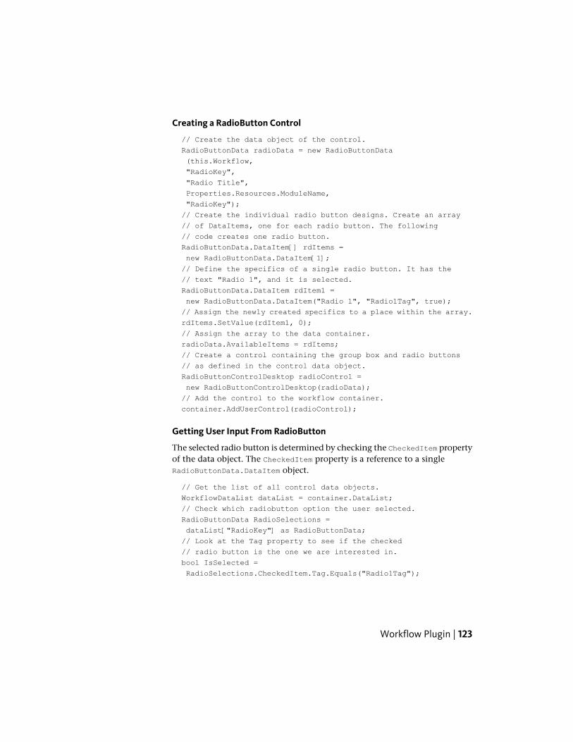
Creating a RadioButton Control
// Create the data object of the control.
RadioButtonData radioData = new RadioButtonData
(this.Workflow,
"RadioKey",
"Radio Title",
Properties.Resources.ModuleName,
"RadioKey");
// Create the individual radio button designs. Create an array
// of DataItems, one for each radio button. The following
// code creates one radio button.
RadioButtonData.DataItem[] rdItems =
new RadioButtonData.DataItem[1];
// Define the specifics of a single radio button. It has the
// text "Radio 1", and it is selected.
RadioButtonData.DataItem rdItem1 =
new RadioButtonData.DataItem("Radio 1", "Radio1Tag", true);
// Assign the newly created specifics to a place within the array.
rdItems.SetValue(rdItem1, 0);
// Assign the array to the data container.
radioData.AvailableItems = rdItems;
// Create a control containing the group box and radio buttons
// as defined in the control data object.
RadioButtonControlDesktop radioControl =
new RadioButtonControlDesktop(radioData);
// Add the control to the workflow container.
container.AddUserControl(radioControl);
Getting User Input From RadioButton
The selected radio button is determined by checking the CheckedItem propertyof the data object. The CheckedItem property is a reference to a singleRadioButtonData.DataItem object.
// Get the list of all control data objects.
WorkflowDataList dataList = container.DataList;
// Check which radiobutton option the user selected.
RadioButtonData RadioSelections =
dataList["RadioKey"] as RadioButtonData;
// Look at the Tag property to see if the checked
// radio button is the one we are interested in.
bool IsSelected =
RadioSelections.CheckedItem.Tag.Equals("Radio1Tag");
Workflow Plugin | 123
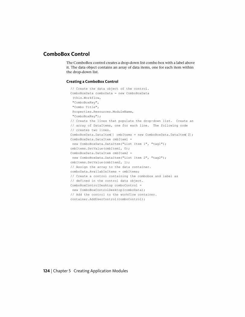
ComboBox ControlThe ComboBox control creates a drop-down list combo box with a label aboveit. The data object contains an array of data items, one for each item withinthe drop-down list.
Creating a ComboBox Control
// Create the data object of the control.
ComboBoxData comboData = new ComboBoxData
(this.Workflow,
"ComboBoxKey",
"Combo Title",
Properties.Resources.ModuleName,
"ComboBoxKey");
// Create the lines that populate the drop-down list. Create an
// array of DataItems, one for each line. The following code
// creates two lines.
ComboBoxData.DataItem[] cmbItems = new ComboBoxData.DataItem[2];
ComboBoxData.DataItem cmbItem1 =
new ComboBoxData.DataItem("List Item 1", "tag1");
cmbItems.SetValue(cmbItem1, 0);
ComboBoxData.DataItem cmbItem2 =
new ComboBoxData.DataItem("List Item 2", "tag2");
cmbItems.SetValue(cmbItem2, 1);
// Assign the array to the data container.
comboData.AvailableItems = cmbItems;
// Create a control containing the combobox and label as
// defined in the control data object.
ComboBoxControlDesktop comboControl =
new ComboBoxControlDesktop(comboData);
// Add the control to the workflow container.
container.AddUserControl(comboControl);
124 | Chapter 5 Creating Application Modules
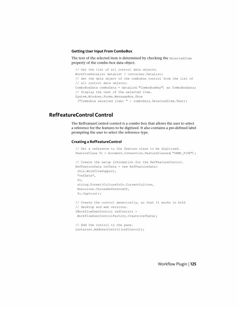
Getting User Input From ComboBox
The text of the selected item is determined by checking the SelectedItemproperty of the combo box data object.
// Get the list of all control data objects.
WorkflowDataList dataList = container.DataList;
// Get the data object of the combobox control from the list of
// all control data objects.
ComboBoxData comboData = dataList["ComboBoxKey"] as ComboBoxData;
// Display the text of the selected item.
System.Windows.Forms.MessageBox.Show
("Combobox selected item: " + comboData.SelectedItem.Text);
RefFeatureControl ControlThe RefFeatureControl control is a combo box that allows the user to selecta reference for the features to be digitized. It also contains a pre-defined labelprompting the user to select the reference type.
Creating a RefFeatureControl
// Get a reference to the feature class to be digitized.
FeatureClass fc = Document.Connection.FeatureClasses["DEMO_PIPE"];
// Create the setup information for the RefFeatureControl.
RefFeatureData refData = new RefFeatureData(
this.WorkflowSupport,
"refData",
fc,
string.Format(CultureInfo.CurrentCulture,
Resources.ChooseReferenceOf,
fc.Caption));
// Create the control generically, so that it works in both
// desktop and web versions.
IWorkflowUserControl refControl =
WorkflowUserControlFactory.Create(refData);
// Add the control to the pane.
container.AddUserControl(refControl);
Workflow Plugin | 125
Getting User Input From RefFeatureControl
WorkflowDataList dataList = container.DataList;
RefFeatureData refData = dataList["refData"] as RefFeatureData;
ChoseFeatureClass ControlThe ChooseFeatureClass control creates a list box populated with a list of allfeature class names. The list box allows selection of multiple lines. It alsocontains a pre-defined label prompting the user to select one of the featureclasses.
Creating a ChooseFeatureClass Control
// Create the data object of the control.
ChooseFeatureClassData chooseClassData = new ChooseFeatureClassData
(this.Workflow,
"ChooseClassKey",
this.Document.Connection.FeatureClasses,
false,
false,
true,
Properties.Resources.ModuleName,
"ChooseClassKey");
// All options to set for the ChooseFeatureClass control are
// set within the constructor for the control data.
// Create a control containing a populated list
// as definied by the control data object.
ChooseFeatureClassControlDesktop chooseClassControl =
new ChooseFeatureClassControlDesktop(chooseClassData);
// Add the control to the workflow container.
container.AddUserControl(chooseClassControl);
126 | Chapter 5 Creating Application Modules
Getting User Input From ChooseFeatureClass
An array of FeatureClass objects is contained in the SelectedFeatureClassesproperty of the ChooseFeatureClassData data object. These FeatureClassobjects represent those items in the list box that are currently selected.
WorkflowDataList dataList = container.DataList;
ChooseFeatureClassData chooseFeatureClassData =
dataList["ChooseClassKey"] as ChooseFeatureClassData;
// Make sure the user selected a feature class.
if (chooseFeatureClassData.SelectedFeatureClasses.Count == 0)
{
// The user didn’t select any feature class. Simply hide the
// user controls and return so the workflow is terminated.
Workflow.WorkflowExplorerFlyIn.HideUserControls();
return;
}
// Get the first FeatureClass object from the list of
// selected feature class names.
FeatureClass selectedFeatureClass =
chooseFeatureClassData.SelectedFeatureClasses[0];
ChoseFeature ControlThe ChooseFeature control consists of a button, group box, and a pre-definedlabel with the number of currently selected features. Pressing the button allowsthe user to select features within the drawing.
Creating a ChooseClass Control
// Create the data object of the control.
ChooseFeatureData choosefeatureData = new ChooseFeatureData
(this.Workflow,
"ChooseKey",
true, /* Allow multiple selection */
true); /* Need at least one feature selected */
// Create a control as defined in the control data object.
ChooseFeatureControlDesktop choosefeatureControl =
new ChooseFeatureControlDesktop(choosefeatureData);
// Add the control to the workflow container.
container.AddUserControl(choosefeatureControl);
Workflow Plugin | 127
Acquisition Workflows - Basics of Digitizing
Using DigitizeFeaturesThe WorkflowSupport.Document.Map object contains a method for digitizingfeatures. Calling DigitizeFeatures() allows the user to create any numberof the specified type of features. The features created is returned as aFeatureList. The prompt to display while digitizing is set by one of theparameters. The workflow application is paused until the user finishes digitizingthe new features or presses Escape to cancel the operation. If the user cancelsthe operation, then DigitizeFeatures() returns a valid list containing zeroelements.
FeatureList digitized;
digitized = this.WorkflowSupport.Document.Map.DigitizeFeatures(
featureClass,
featureClass.Type,
"Please digitize a " + featureClass.Caption,
null,
true);
Digitizing Utility FeaturesIf you need to digitize node or line features into a utility network (such as awater pipe or electrical network), then use the digitize methods of theUtilityFeatreClass class.
UtilityFeatureClass represents a feature class that is part of a utility. Objectsof this type are created by the static factory class UtilityFeatureClassFactory.UtilityFeatureClass contains the methods Digitize() andDigitizeMultiple(), which allow the user to create new utility features withinthe document.
NOTE No prompt is displayed to the user. You should use ShowMessage (or someother method) to tell the user what state they are in and what action they shouldtake.
The following sample creates an instance of the UtilityFeatureClass basedon the existing DEMO_PIPE feature class using theUtilityFeatureClassFactory. It then loops, allowing the user to create any
128 | Chapter 5 Creating Application Modules
number of individual DEMO_PIPE features, which represent lines within thewater utility network:
FeatureClass fc;
fc = Document.Connection.FeatureClasses["DEMO_PIPE"];
UtilityFeatureClass pipeUfc;
pipeUfc UtilityFeatureClassFactory.GetInstance(fc);
ArrayList pipes = new ArrayList();
bool newPipe = true;
while (newPipe)
{
// Give the user a prompt.
this.WorkflowSupport.WorkflowExplorerFlyIn.
ShowMessage("Digitize Pipe. Press ESC to exit.");
UtilityLine pipe = pipeUfc.Digitize(Document) as UtilityLine;
if (pipe == null)
{
newPipe = false;
break;
}
pipes.Add(pipe);
}
The UtilityFeatureClass class contains many other methods that can beuseful in workflows:
■ ConvertFeature - Allows the user select a feature in the document that isconverted to a utility feature and returned.
■ HighlightFeatures - Takes an array of utility features and highlights themin the display. It can optionally zoom the display to show all thehighlighted features.
■ SelectSingleFeatureInGraphic - Allows the user to select a utility featurein the document. It can optionally return which line segment of the featurewas selected.
Workflow Plugin | 129
Analysis Workflows - Basics of Analysis
Selecting Points and RegionsYou can prompt the user to select points, rectangles, or polygons within thedocument by using methods of the WorkflowSupport.Document.Map object.
GetPoint() gives the user a prompt that is displayed as a tooltip by the cursorand in the command window. The method returns the point location in themap where the user clicked. The workflow application is paused until the userselects a point or presses Escape to cancel the operation.
// The prompt says "Select Point".
Topobase.Graphic.Point pt;
pt = this.WorkflowSupport.Document.Map.GetPoint("Select Point");
GetRectangle() gives the user a prompt that is displayed as a tooltip by thecursor and in the command window. The method returns the polygon regionin the map defined by two clicks from the user. The workflow application ispaused until the user selects the rectangle or presses Escape to cancel theoperation.
Topobase.Graphic.Polygon rect;
rect = this.WorkflowSupport.Document.Map.
GetRectangle("First Corner", "Second Corner");
GetPolygon() also gives the user a prompt that is displayed as a tooltip by thecursor and in the command window. The method returns the polygon regionin the map defined by at least three clicks from the user. The workflowapplication is paused until the user selects the region or presses Escape tocancel the operation.
Topobase.Graphic.Polygon poly;
poly = this.WorkflowSupport.Document.Map.
GetPolygon("Select Polygon");
Selecting Features in the DocumentOne way for the user to select features in the document is to call theGetFeatures() method of the WorkflowSupport.Document.Map object.GetFeatures() allows the user to select any number of features (either one at
130 | Chapter 5 Creating Application Modules
a time or through selection windows and crossing windows) until they pressthe Enter key. The features selected are returned as a FeatureList as follows:
FeatureList features;
features = this.WorkflowSupport.Document.Map.GetFeatures();
NOTE You cannot set the prompt; it automatically displays the text “SelectEntities”. The workflow application is paused until the user finishes selecting featuresor presses Escape to cancel the operation.
Installation
Adding Workflows AutomaticallyIf your workflow class is part of a vertical application, you can add yourworkflow to the workspace while creating your data model. This is done usingthe AddOrUpdateWorkflow() method.
There are many different overridden versions of the AddOrUpdateWorkflowmethod, but there are two general forms. Most versions have you pass thesame information as you would manually enter in the Workflow Administratorpage of the Autodesk Topobase Administrator. The following example createsa new workflow by passing the workflow name, the caption to be displayedin Autodesk Topobase, the path to the icon file, the priority value, the scriptcode, and a boolean value indicating that this workflow should not be modifiedby the user.
AddOrUpdateWorkflow(
"DEMO ACQUISITION ParentNode",
Resources.WorkflowNameAcquisition,
NodeWorkflowPictureName,
0,
null, true);
NOTE This particular sample passes a null string for the script code, which meansthat this entry in the list of workflows does not actually do anything, but it canserve as the parent of other workflows for organizational purposes.
Another overridden form of the AddOrUpdateWorkflow method takes a referenceto the workflow entry point method and a reference to the resource thatcontains the caption string. Attached to the entry point method is a series of
Workflow Plugin | 131
function attributes defining the icon file path, priority, and other settings thatwould normally be passed to AddOrUpdateWorkflow as parameters.
The following example features the AddOrUpdateWorkflow method:
// In a structure update module where the data model
// is defined.
public override void UpdateStructure()
{
AcquisitionWorkflows acquisitionWorkflowInstance =
new AcquisitionWorkflows();
AddOrUpdateWorkflow(
acquisitionWorkflowInstance.NetworkPipeCreation,
Resources.ResourceManager);
}
// Inside the workflow plugin class.
// Set the function attributes describing the workflow.
[WorkflowMethodDescription(
AcquisitionWorkflows.WorkflowNameCreateNetworkPipe,
"WorkflowNameNetworkPipeCreation",
"WaterPipeCreation",
1, // Priority
ParentWorkflowName = "DEMO ACQUISITION ParentNode",
IsSystem = false)]
public void EntryPoint()
{
[...]
NOTE The benefit of this is to locate all the workflow-related settings within theworkflow class itself for easier editing. A vertical application might contain a largenumber of very complicated structure update classes, and it can be hard to locatethe correct AddOrUpdateWorkflow method to make changes.
Adding Workflows Manually Using AdministratorIf your workflow is located in a stand-alone class library file (that is, astandalone .dll), you must add your workflow information manually.
132 | Chapter 5 Creating Application Modules
To add your workflow manually into the Autodesk Topobase Administrator:
1 Build the project. Place the plugin library into the Autodesk TopobaseClient bin directory. The associated .tbp file must also be copied to theAutodesk Topobase Client bin directory.
2 Launch the Autodesk Topobase Administrator application and load yourworkspace.
3 In the left pane, under the appropriate document, select the Workflowsfolder.
4 In the Workflow Administrator page, click Create.
5 In the Create Workflow dialog box, enter a name for the workspace andclick Create.
6 Create a script in the Script Code edit field that uses the Me.RunMethodfunction to call the entry point function in your plugin library. The firstparameter is the filename of the workflow library. The second parameteris the namespace and class name of the workflow. The third parameteris the name of the entry point method.
Sub Run
Me.RunMethod("workflow.dll",
"ProjectName.ClassName", "EntryPointFunction")
End Sub
7 Click the Save button.
Organizing Workflows
You can organize workflows in a hierarchy by creating blank workflows usingthe AddOrUpdateWorkflow method while passing a null string for the ScriptCode parameter. These blank workflows can act as parents for your functionalworkflows. Assign the child workflows by using one of the overloads of theAddOrUpdateWorkflow method that takes a parent workflow object as aparameter.
Creating User Interface PluginsUser interface plugins are small applications that provide functionality to theAutodesk Topobase user, usually by creating a new control integrated intosome part of the Autodesk Topobase client user interface. There are manydifferent kinds of plugins that correspond to the different user interface
Creating User Interface Plugins | 133
elements of Autodesk Topobase and to the different levels of information (thatis, application-wide tasks, single document tasks, or single table tasks).
Creating an Application Plugin
About Application PluginsApplication plugins are a mechanism for performing application-wideoperations. They may run without a user interface until an application eventfires, or they may modify the application menu bar or add application toolbarsand toolbar buttons to the Autodesk Topobase task pane.
NOTE The application menu bar is only visible in the stand-alone AutodeskTopobase Client application or in the desktop Autodesk Topobase Client applicationwhen no workspace is loaded. If a workspace is loaded in the desktop AutodeskTopobase Client, the menu bar is not visible.
134 | Chapter 5 Creating Application Modules
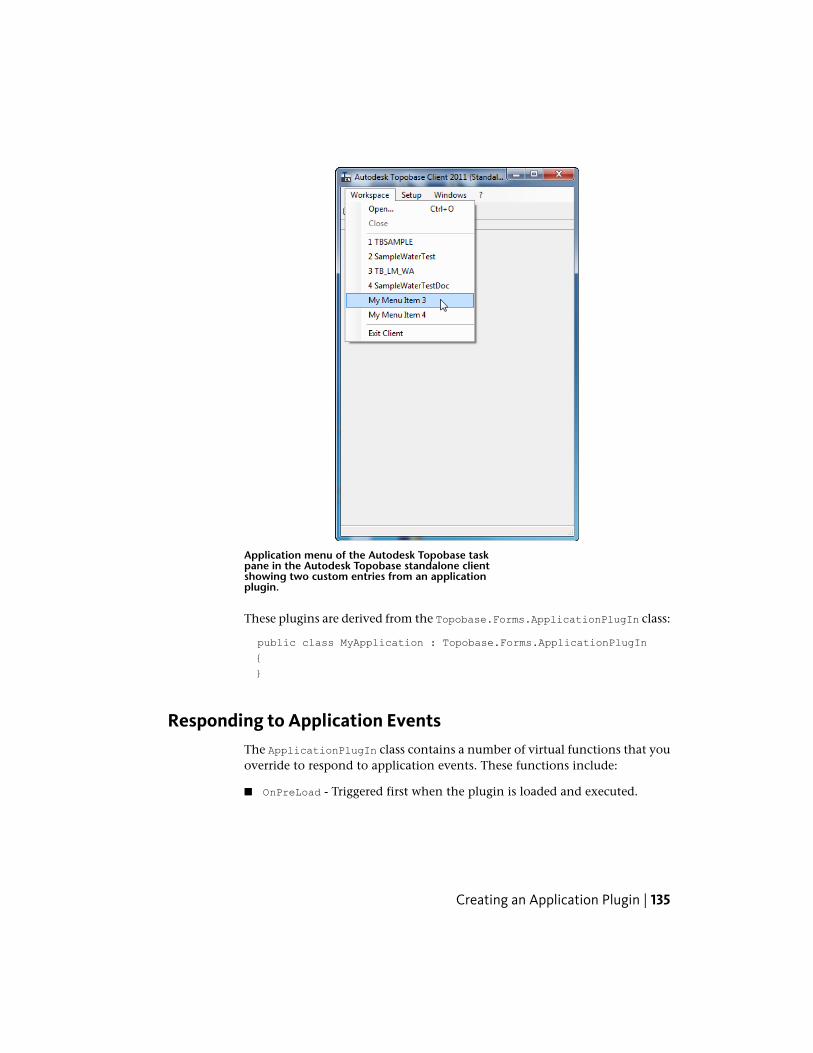
Application menu of the Autodesk Topobase taskpane in the Autodesk Topobase standalone clientshowing two custom entries from an applicationplugin.
These plugins are derived from the Topobase.Forms.ApplicationPlugIn class:
public class MyApplication : Topobase.Forms.ApplicationPlugIn
{
}
Responding to Application EventsThe ApplicationPlugIn class contains a number of virtual functions that youoverride to respond to application events. These functions include:
■ OnPreLoad - Triggered first when the plugin is loaded and executed.
Creating an Application Plugin | 135
■ OnLoad - Triggered during the initialization process when the plugin isloaded and executed.
■ OnInitComplete - Triggered after the initialization process is complete.
■ OnInitMenus - Override this event to create application menu items.
■ OnUnload - Triggered when the plugin is unloaded.
NOTE Not triggered when the Autodesk Topobase Client is closed.
In the following example, an application plugin named “MyApplication”displays a dialog box when the plugin is first loaded:
public class MyApplication : Topobase.Forms.ApplicationPlugIn
{
public override void OnLoad(object sender, EventArgs e)
{
base.OnLoad(sender, e);
// Display the dialog box (defined elsewhere).
Form1 theForm = new Form1();
theForm.Show();
}
}
Adding Custom Toolbars and Toolbar ButtonsBy default, no application toolbars are shown in the Autodesk Topobase taskpane. Application plugins can create new toolbars by passing a stringcontaining the new toolbar name to the Item property of the ToolBarscollection. These toolbars can be shared between different plugins if they usethe same toolbar name. For more information about adding toolbars, seeSample 72 - Application Toolbar (page 264).
136 | Chapter 5 Creating Application Modules
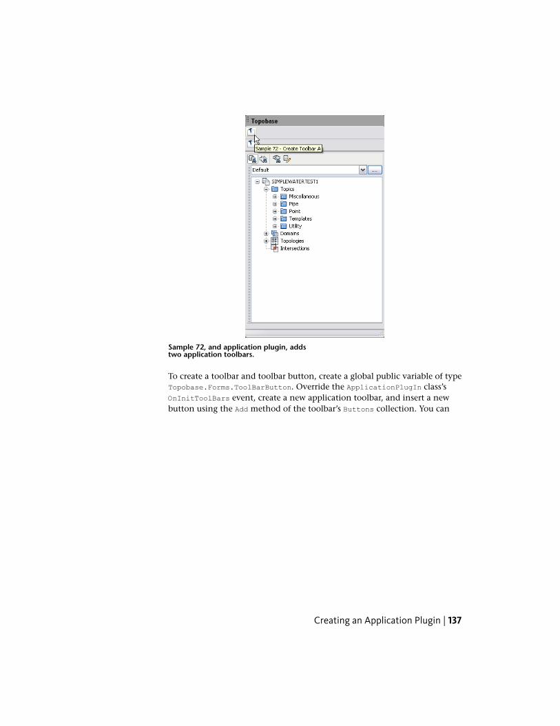
Sample 72, and application plugin, addstwo application toolbars.
To create a toolbar and toolbar button, create a global public variable of typeTopobase.Forms.ToolBarButton. Override the ApplicationPlugIn class’sOnInitToolBars event, create a new application toolbar, and insert a newbutton using the Add method of the toolbar’s Buttons collection. You can
Creating an Application Plugin | 137
then create an event handler for the new button and can respond to buttonevents. For example:
public Topobase.Forms.ToolBarButton myToolbarButton =
new Topobase.Forms.ToolBarButton();
public override void OnInitToolBars
(object sender, Topobase.Forms.Events.ToolBarsEventArgs e)
{
// Create a custom toolbar.
Topobase.Forms.ToolBar customToolbar;
customToolbar = e.ToolBars.Item("Custom Toolbar");
// Add a new toolbar button to the application toolbar
// using the "Topobase" icon and "My Toolbar Button"
// as the tooltip text.
customToolbar.Buttons.Add
(myToolbarButton,
"Topobase",
"My Toolbar Button");
// Add event handler for the button.
myToolbarButton.Click +=
new EventHandler(myToolbarButton_Click);
}
private void myToolbarButton_Click
(object sender, System.EventArgs e)
{
// Perform the plugin action here.
this.Application.MessageBox("Toolbar button was clicked");
}
Adding Menu ItemsTo add a menu item, create a public variable of type Topobase.Forms.MenuItem.Override the ApplicationPlugIn class’s OnInitMenus method (which is triggeredwhen the menu initialization is taking place), obtain a reference to theapplication menu, and insert a new menu item using the Add method of the
138 | Chapter 5 Creating Application Modules
menu’s MenuItems collection. You can then create an event handler for thenew menu item and can respond to menu events. For example:
public Topobase.Forms.MenuItem myMenu =
new Topobase.Forms.MenuItem();
public override void OnInitMenus
(object sender, Topobase.Forms.Events.MenusEventArgs e)
{
// Get the application's project menu.
Topobase.Forms.Menu vlobMenu =
e.Menus.Item(Topobase.Forms.ApplicationMenuType.Workspace);
// Add the new menu item.
vlobMenu.MenuItems.Add(myMenu, "My Menu Item");
// Bind the events.
myMenu.Click += new Topobase.Forms.Events.
MenuItemClickEventHandler(myMenu_Click);
}
private void myMenu_Click
(object sender, Topobase.Forms.Events.MenuItemClickEventArgs e)
{
// Perform the plugin action here.
this.Application.MessageBox("Menu item was clicked");
}
Creating a Document Plugin
About Document PluginsDocument plugins are a mechanism for performing document-level operations.They can set up event handlers for document-level notifications, or they canadd new features to the user interface. For example, a document plugin canset up an event handler for job state transitions, and perform client-sidevalidation or reports prior to a job being committed to the “Live” state.Document plugins can also modify the user interface by adding items to thedocument toolbar or menu items to the context menus within the Autodesk
Creating a Document Plugin | 139
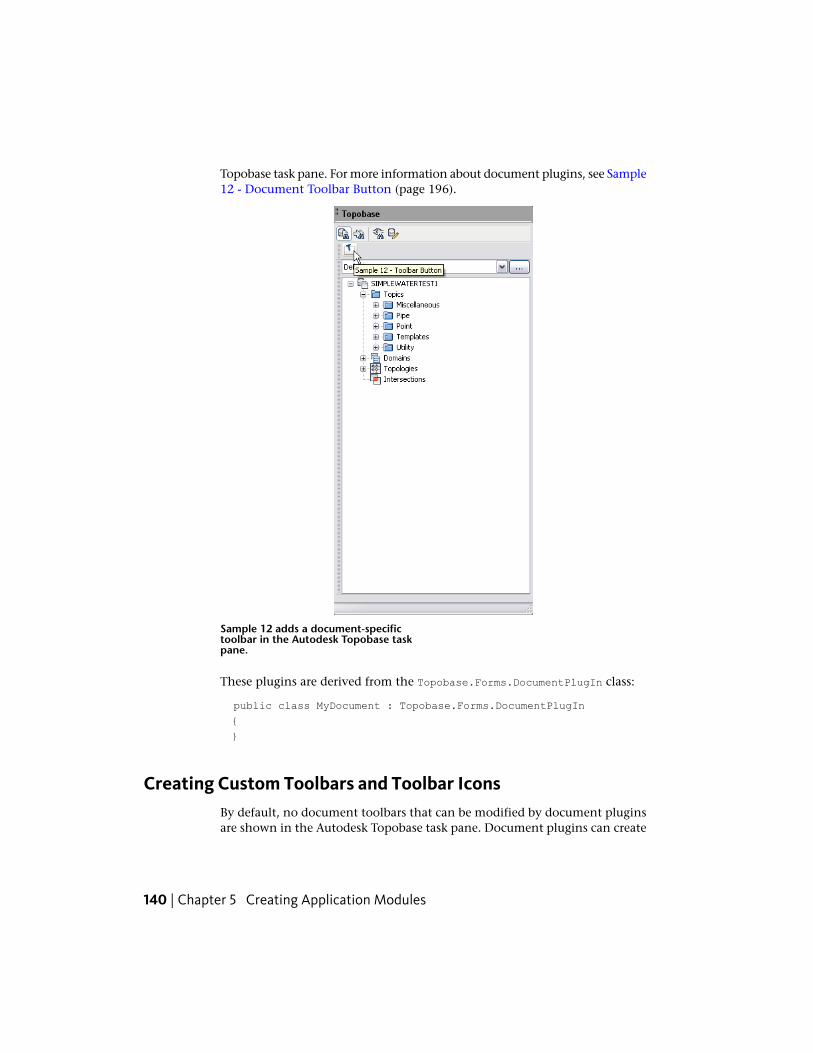
Topobase task pane. For more information about document plugins, see Sample12 - Document Toolbar Button (page 196).
Sample 12 adds a document-specifictoolbar in the Autodesk Topobase taskpane.
These plugins are derived from the Topobase.Forms.DocumentPlugIn class:
public class MyDocument : Topobase.Forms.DocumentPlugIn
{
}
Creating Custom Toolbars and Toolbar IconsBy default, no document toolbars that can be modified by document pluginsare shown in the Autodesk Topobase task pane. Document plugins can create
140 | Chapter 5 Creating Application Modules
new toolbars by passing a string containing the new toolbar name to the Itemproperty of the ToolBars collection. These toolbars can be shared betweendifferent plugins if they use the same toolbar name.
To create a toolbar and toolbar button, create a global public variable of typeTopobase.Forms.ToolBarButton. Override the DocumentPlugIn class’sOnInitToolBars event, create a new toolbar, and insert a new button usingthe Add method of the toolbar’s Buttons collection. You can then create anevent handler for the new button and can respond to button events. Forexample:
public Topobase.Forms.ToolBarButton myToolbarButton =
new Topobase.Forms.ToolBarButton();
public override void OnInitToolBars
(object sender, Topobase.Forms.Events.ToolBarsEventArgs e)
{
// Create a custom toolbar.
Topobase.Forms.ToolBar customToolbar;
customToolbar = e.ToolBars.Item("Custom Toolbar");
// Add a new toolbar button to the document toolbar
// using the "Topobase" icon and "My Toolbar Button"
// as the tooltip text.
mainToolbar.Buttons.Add
(myToolbarButton, "Topobase", "My Toolbar Button");
myToolbarButton1.Click +=
new EventHandler(myToolbarButton_Click);
}
private void myToolbarButton_Click
(object sender, System.EventArgs e)
{
// Perform the plugin action here.
this.Application.MessageBox("Toolbar button was clicked");
}
Creating a Document Plugin | 141
Modifying the Context Menu
To create a new menu item within the Document Explorer’s context menu
1 Create a public class variable of type Topobase.Forms.MenuItem. Thisserves as the communication point between Autodesk Topobase and yourplugin.
2 Override the DocumentPlugIn class’s OnInitMenus event so you can modifythe menus at the correct time after they have been created.
3 Obtain a reference to the specific document’s context menu you want tomodify. There are a collection of MenuItem menus, each assigned to aspecific feature class. This way you can add menu items only to thecontext menu of the particular feature class you want.
4 Insert a new menu item using the Add method of the menu’s MenuItemscollection
5 Add an event handler for the Click event of the new menu item.
The following example demonstrates these steps. It adds a new menu item tothe context menu of “Point” feature classes. When you right click on a “Point”
142 | Chapter 5 Creating Application Modules
feature class in the Document Explorer, you see a new menu item called MyMenu Item, which displays a message box when selected.
public Topobase.Forms.MenuItem myMenuItem1 =
new Topobase.Forms.MenuItem();
public override void OnInitMenus
(object sender, Topobase.Forms.Events.MenusEventArgs e)
{
// Obtain the context menu to which you want to add
// your new MenuItem.
Topobase.Forms.Menu pointMenu =
e.Menus.Item(Topobase.Data.FeatureClassType.Point);
// Add your MenuItem to the menu.
pointMenu.MenuItems.Add(myMenuItem, "My Menu Item");
myMenuItem1.Click += new Topobase.Forms.Events.
MenuItemClickEventHandler(MyMenuItem_Click);
}
private void MyMenuItem_Click
(object sender, Topobase.Forms.Events.MenuItemClickEventArgs e)
{
// Perform the plugin action here.
this.Application.MessageBox("Menu Item Clicked");
}
Creating a Document Plugin | 143
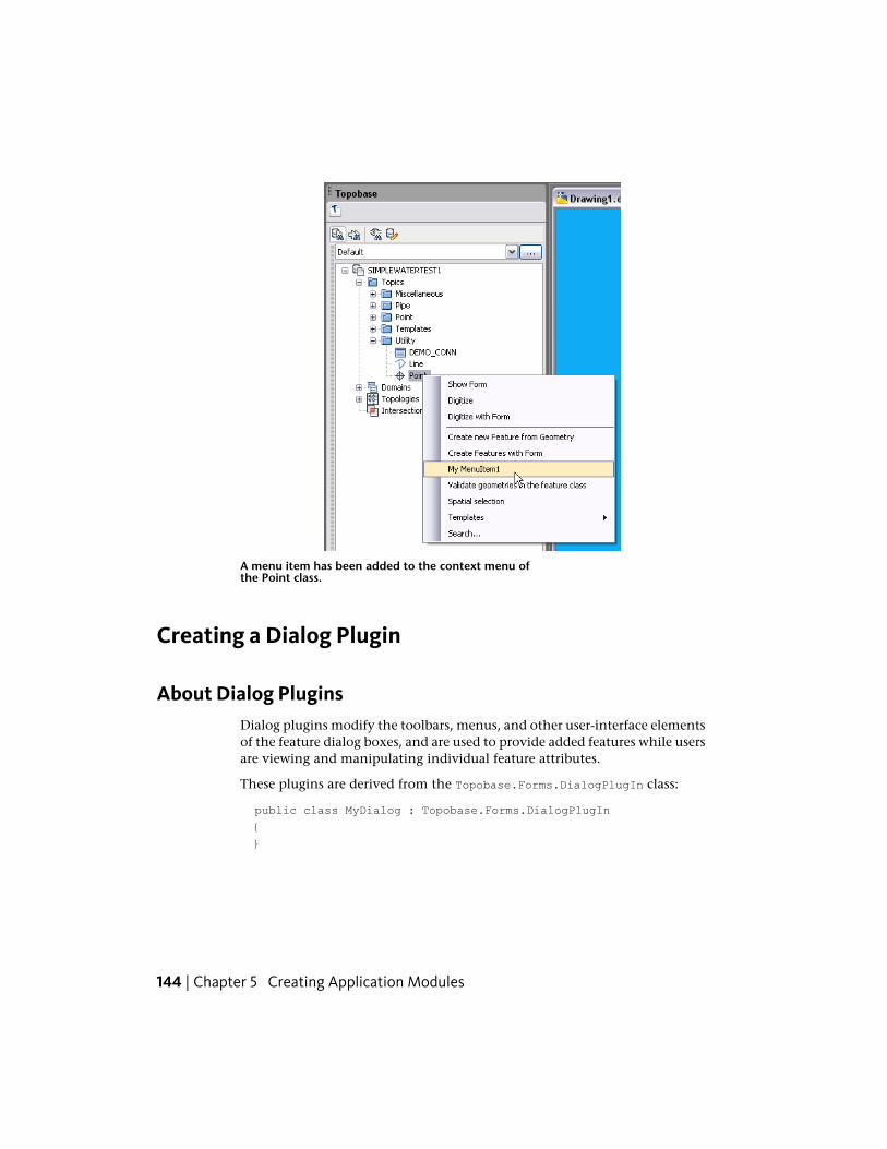
A menu item has been added to the context menu ofthe Point class.
Creating a Dialog Plugin
About Dialog PluginsDialog plugins modify the toolbars, menus, and other user-interface elementsof the feature dialog boxes, and are used to provide added features while usersare viewing and manipulating individual feature attributes.
These plugins are derived from the Topobase.Forms.DialogPlugIn class:
public class MyDialog : Topobase.Forms.DialogPlugIn
{
}
144 | Chapter 5 Creating Application Modules
Creating Toolbar ItemsTo create a toolbar icon, create a public variable of typeTopobase.Forms.ToolBarButton. Override the DialogPlugIn class’sOnInitToolBar event, obtain a reference to the dialog toolbar, and insert thenew button using the Add method of the toolbar’s Buttons collection. Youcan then create an event handler for the new toolbar button and can respondto toolbar events. For example:
public Topobase.Forms.ToolBarButton myToolbarButton =
new Topobase.Forms.ToolBarButton();
public override void OnInitToolBar
(object sender, Topobase.Forms.Events.ToolBarEventArgs e)
{
// Add a new toolbar button to the toolbar of the
// generic dialogs.
e.ToolBar.Buttons.Add
(myToolbarButton,
"Topobase",
"My Toolbar Button");
myToolbarButton3.Click +=
new EventHandler(myToolbarButton_Click);
}
// Event is raised when the button is clicked.
private void myToolbarButton_Click
(object sender, System.EventArgs e)
{
// Perform the plugin action here.
this.Application.MessageBox("Toolbar button clicked");
}
Creating a Menu BarGeneric dialog boxes generally do not have menu bars, but it is possible toadd them. To create a menu, create public variables of typeTopobase.Forms.MenuItem for each menu title and menu item. Override theDialogPlugIn class’s OnInitMenu event, obtain a reference to the applicationmenu bar, and insert a new menu title using the Add method of the menu’sMenuItems collection. Submenus for each menu title can be added using the
Creating a Dialog Plugin | 145
Add method of the menu title’s MenuItems collection. You can then create anevent handler for the new menu items and can respond to menu events. Forexample:
// Create a Main Menu Item "File".
public Topobase.Forms.MenuItem mnuFile =
new Topobase.Forms.MenuItem();
// Create two Menu Items as sub-menus "Open".
public Topobase.Forms.MenuItem mnuFileOpen =
new Topobase.Forms.MenuItem();
public override void OnInitMenu
(object sender, Topobase.Forms.Events.MenuEventArgs e)
{
// Add the Main Menu Item.
e.Menu.MenuItems.Add(mnuFile, "&File");
// Add SubMenuOItems to the Menu "File".
mnuFile.MenuItems.Add(mnuFileOpen, "&Open");
// Bind the event handlers.
mnuFileOpen.Click += new Topobase.Forms.Events.
MenuItemClickEventHandler(mnuFileOpen_Click);
}
private void mnuFileOpen_Click
(object sender, Topobase.Forms.Events.MenuItemClickEventArgs e)
{
// Perform the plugin action here.
this.Application.MessageBox("File Open clicked");
}
Adding Controls to a DialogAutodesk Topobase-specific controls, such as buttons and list boxes, can beadded to dialog boxes using the Autodesk Topobase Administrator (for anexample, see the Sample 16 - Dialog Button (page 203) Help). To create a pluginthat responds to events from such controls, create variables of the correctTopobase.Forms type for each control. When the plugin is loaded, obtainreferences to the dialog controls using the this.Dialog.Controls.ApiItem
146 | Chapter 5 Creating Application Modules
method using the name of the control assigned through Autodesk TopobaseAdministrator. You can then create an event handler for the dialog controland can respond to control events. For example:
private Topobase.Forms.Button myButton;
public MyDialog()
{
// We cannot get access to the dialog controls in the
// constructor. Instead, create an event handler
// for the load event, and get access to the dialog controls
// in there.
this.Load += new EventHandler(MyDialog_Load);
}
private void MyDialog_Load(object sender, EventArgs e)
{
// Get a reference to the button already added to the
// dialog using Autodesk Topobase Administrator.
myButton1 = this.Dialog.Controls.ApiItem("$myButton")
as Topobase.Forms.Button;
// Add an event handler to catch when the button is selected.
myButton1.Click += new System.EventHandler(MyButton_Click);
}
private void MyButton_Click
(System.Object sender, System.EventArgs e)
{
// Perform the plugin action here.
this.Application.MessageBox("Button clicked");
}
Creating an Application Flyin
About Application FlyinsAn application flyin is a dockable, moveable window that can be dockedwithin the Autodesk Topobase application part of the Autodesk Topobase task
Creating an Application Flyin | 147
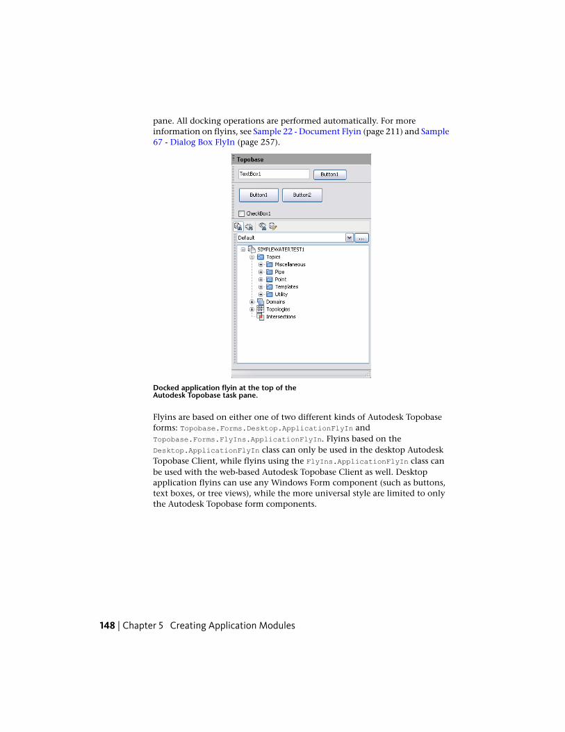
pane. All docking operations are performed automatically. For moreinformation on flyins, see Sample 22 - Document Flyin (page 211) and Sample67 - Dialog Box FlyIn (page 257).
Docked application flyin at the top of theAutodesk Topobase task pane.
Flyins are based on either one of two different kinds of Autodesk Topobaseforms: Topobase.Forms.Desktop.ApplicationFlyIn andTopobase.Forms.FlyIns.ApplicationFlyIn. Flyins based on theDesktop.ApplicationFlyIn class can only be used in the desktop AutodeskTopobase Client, while flyins using the FlyIns.ApplicationFlyIn class canbe used with the web-based Autodesk Topobase Client as well. Desktopapplication flyins can use any Windows Form component (such as buttons,text boxes, or tree views), while the more universal style are limited to onlythe Autodesk Topobase form components.
148 | Chapter 5 Creating Application Modules
The following sample shows the code behind aTopobase.Forms.FlyIns.ApplicationFlyIn fly-in that contains a single button.In response to a button click, it displays a message box:
public class MyApplicationFlyIn :
Topobase.Forms.FlyIns.ApplicationFlyIn
{
private void MyApplicationFlyIn_Load
(object sender, System.EventArgs e)
{
// Set the flyin title.
this.Text = "Sample FlyIn";
}
// This flyin contains a single button.
private void Button1_Click
(object sender, System.EventArgs e)
{
this.Application.MessageBox(this.TextBox1.Text);
}
}
Creating a Document Flyin
About Document FlyinsA document flyin is a dockable, moveable window that can be docked withinthe Autodesk Topobase document tabs of the Autodesk Topobase task pane.All docking operations are performed automatically.
Flyins are based on either one of two different kinds of Autodesk Topobaseforms: Topobase.Forms.Desktop.DocumentFlyIn andTopobase.Forms.FlyIns.DocumentFlyIn. Flyins based on theDesktop.DocumentFlyIn class can only be used in the desktop AutodeskTopobase Client, while flyins using the FlyIns.DocumentFlyIn class can beused with the web-based Autodesk Topobase Client as well. Desktop documentflyins can use any Windows Form component (such as buttons, text boxes,or tree views), while the more universal style are limited to only the AutodeskTopobase form components.
Creating a Document Flyin | 149
The following sample shows the code behind aTopobase.Forms.FlyIns.DocumentFlyIn fly-in that contains a single button.In response to a button click, it displays a message box:
public class MyDocumentFlyIn :
Topobase.Forms.FlyIns.DocumentFlyIn
{
private void MyDocumentFlyIn_Load
(object sender, System.EventArgs e)
{
// Set the flyin title.
this.Text = "Sample FlyIn";
}
// This flyin contains a single button.
private void Button1_Click
(object sender, System.EventArgs e)
{
this.Application.MessageBox(this.TextBox1.Text);
}
}
Creating a Dialog Flyin
About Dialog FlyinsA dialog flyin is a frame within Autodesk Topobase dialog boxes. Unlike otherkinds of flyins, these cannot be undocked and moved.
150 | Chapter 5 Creating Application Modules
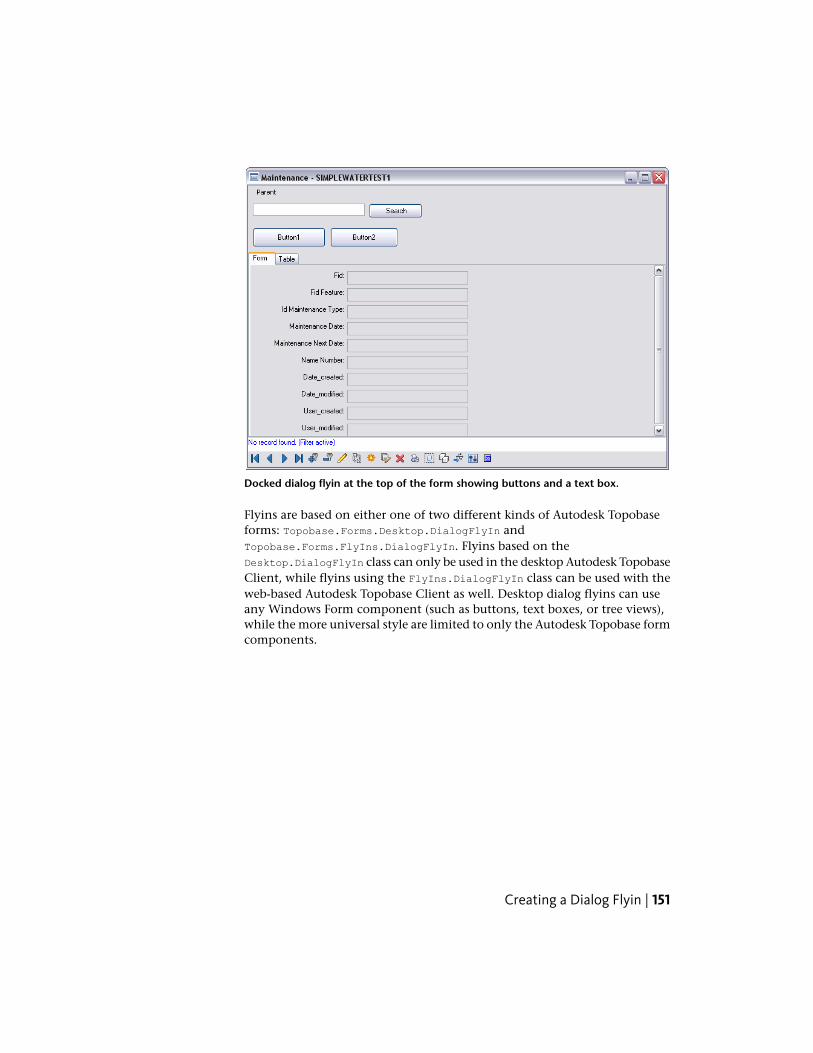
Docked dialog flyin at the top of the form showing buttons and a text box.
Flyins are based on either one of two different kinds of Autodesk Topobaseforms: Topobase.Forms.Desktop.DialogFlyIn andTopobase.Forms.FlyIns.DialogFlyIn. Flyins based on theDesktop.DialogFlyIn class can only be used in the desktop Autodesk TopobaseClient, while flyins using the FlyIns.DialogFlyIn class can be used with theweb-based Autodesk Topobase Client as well. Desktop dialog flyins can useany Windows Form component (such as buttons, text boxes, or tree views),while the more universal style are limited to only the Autodesk Topobase formcomponents.
Creating a Dialog Flyin | 151
The following sample shows the code behind aTopobase.Forms.FlyIns.DialogFlyIn flyin that contains a single button. Inresponse to a button click, it displays a message box:
public class MyDialogFlyIn : Topobase.Forms.FlyIns.DialogFlyIn
{
private void MyDialogFlyIn_Load
(object sender, System.EventArgs e)
{
// Set the flyin title.
this.Text = "Sample FlyIn";
}
// This flyin contains a single button.
private void Button1_Click
(object sender, System.EventArgs e)
{
this.Application.MessageBox(this.TextBox1.Text);
}
}
User Interaction
Using Forms
Basics of Using Forms
When designing plugin and flyin forms, be sure to take into account the sizeand shape of the area where the form is displayed. Plugin forms and flyinforms based on Topobase.Forms.Desktop.ApplicationFlyIn allow you to usethe standard Windows Anchor and AutoSize properties for controls, whichcan help you create forms that are useable and attractive in a wide variety ofsituations.
Using Autodesk Topobase Forms in Visual Studio
For more information on setting up Visual Studio to use Autodesk Topobaseform classes, see Installing the Item Templates (page 161).
152 | Chapter 5 Creating Application Modules
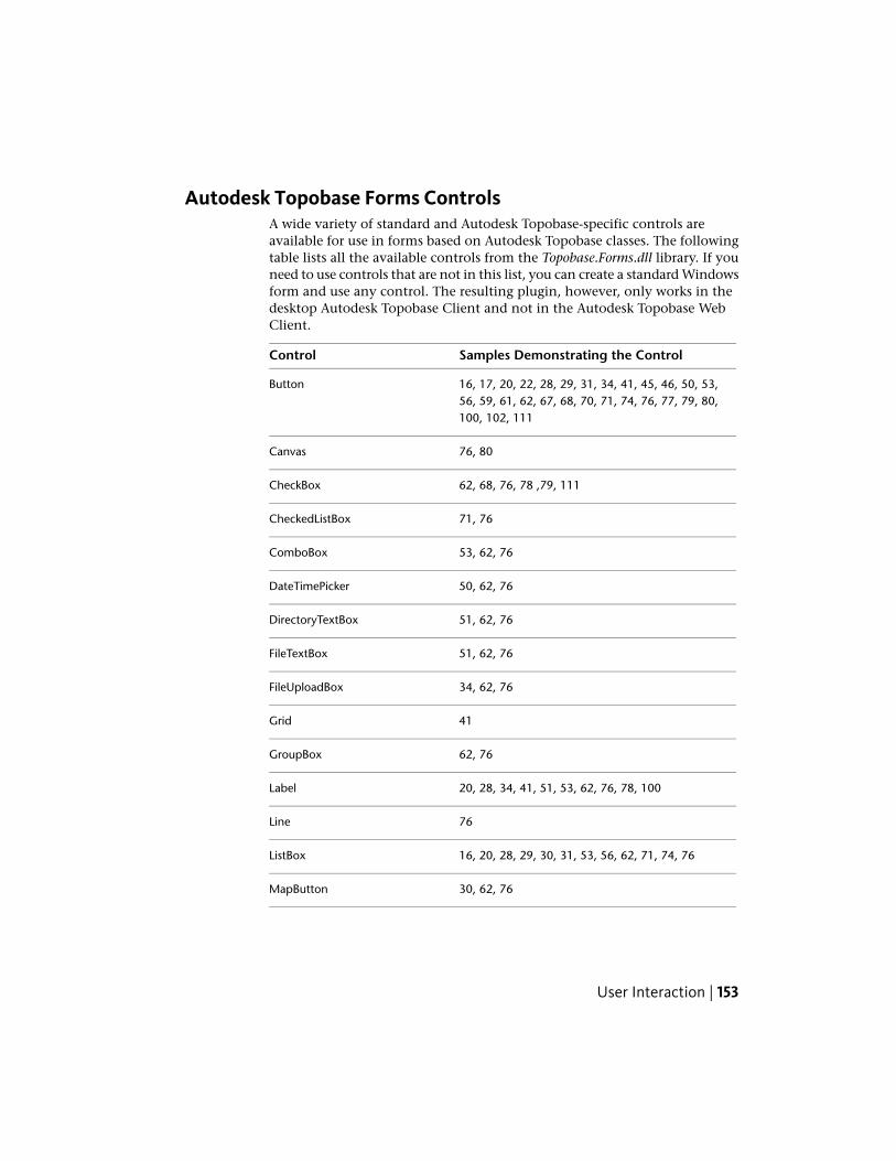
Autodesk Topobase Forms ControlsA wide variety of standard and Autodesk Topobase-specific controls areavailable for use in forms based on Autodesk Topobase classes. The followingtable lists all the available controls from the Topobase.Forms.dll library. If youneed to use controls that are not in this list, you can create a standard Windowsform and use any control. The resulting plugin, however, only works in thedesktop Autodesk Topobase Client and not in the Autodesk Topobase WebClient.
Samples Demonstrating the ControlControl
16, 17, 20, 22, 28, 29, 31, 34, 41, 45, 46, 50, 53,56, 59, 61, 62, 67, 68, 70, 71, 74, 76, 77, 79, 80,100, 102, 111
Button
76, 80Canvas
62, 68, 76, 78 ,79, 111CheckBox
71, 76CheckedListBox
53, 62, 76ComboBox
50, 62, 76DateTimePicker
51, 62, 76DirectoryTextBox
51, 62, 76FileTextBox
34, 62, 76FileUploadBox
41Grid
62, 76GroupBox
20, 28, 34, 41, 51, 53, 62, 76, 78, 100Label
76Line
16, 20, 28, 29, 30, 31, 53, 56, 62, 71, 74, 76ListBox
30, 62, 76MapButton
User Interaction | 153
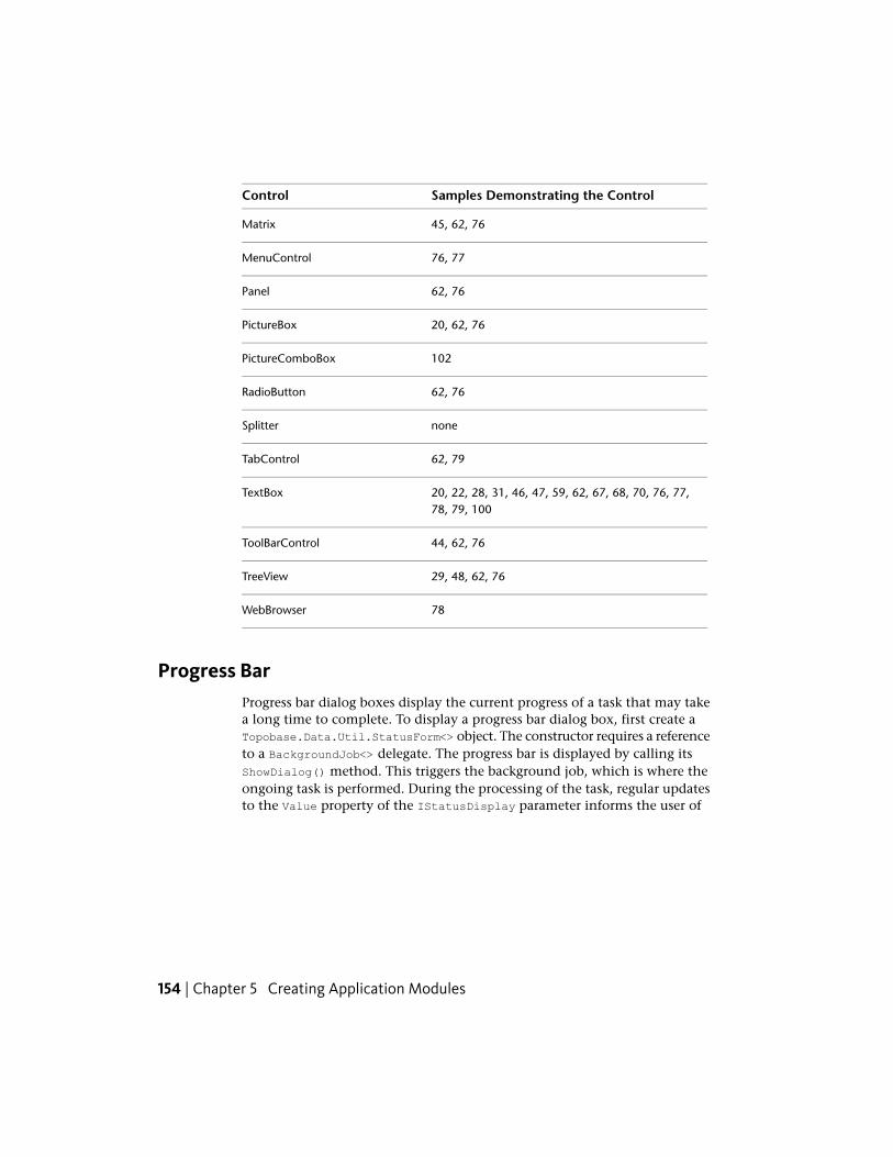
Samples Demonstrating the ControlControl
45, 62, 76Matrix
76, 77MenuControl
62, 76Panel
20, 62, 76PictureBox
102PictureComboBox
62, 76RadioButton
noneSplitter
62, 79TabControl
20, 22, 28, 31, 46, 47, 59, 62, 67, 68, 70, 76, 77,78, 79, 100
TextBox
44, 62, 76ToolBarControl
29, 48, 62, 76TreeView
78WebBrowser
Progress BarProgress bar dialog boxes display the current progress of a task that may takea long time to complete. To display a progress bar dialog box, first create aTopobase.Data.Util.StatusForm<> object. The constructor requires a referenceto a BackgroundJob<> delegate. The progress bar is displayed by calling itsShowDialog() method. This triggers the background job, which is where theongoing task is performed. During the processing of the task, regular updatesto the Value property of the IStatusDisplay parameter informs the user of
154 | Chapter 5 Creating Application Modules

the current task status. Once the background job is complete, the progress baris automatically removed.
User Interaction | 155
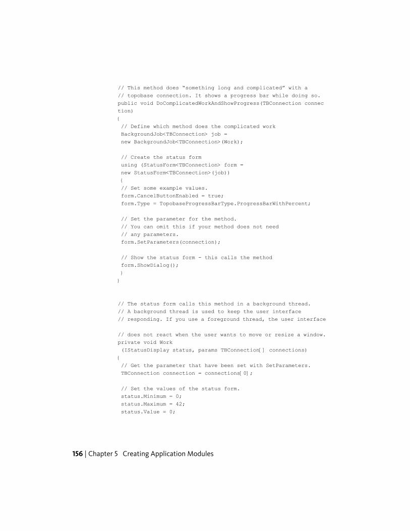
// This method does “something long and complicated” with a
// topobase connection. It shows a progress bar while doing so.
public void DoComplicatedWorkAndShowProgress(TBConnection connec
tion)
{
// Define which method does the complicated work
BackgroundJob<TBConnection> job =
new BackgroundJob<TBConnection>(Work);
// Create the status form
using (StatusForm<TBConnection> form =
new StatusForm<TBConnection>(job))
{
// Set some example values.
form.CancelButtonEnabled = true;
form.Type = TopobaseProgressBarType.ProgressBarWithPercent;
// Set the parameter for the method.
// You can omit this if your method does not need
// any parameters.
form.SetParameters(connection);
// Show the status form - this calls the method
form.ShowDialog();
}
}
// The status form calls this method in a background thread.
// A background thread is used to keep the user interface
// responding. If you use a foreground thread, the user interface
// does not react when the user wants to move or resize a window.
private void Work
(IStatusDisplay status, params TBConnection[] connections)
{
// Get the parameter that have been set with SetParameters.
TBConnection connection = connections[0];
// Set the values of the status form.
status.Minimum = 0;
status.Maximum = 42;
status.Value = 0;
156 | Chapter 5 Creating Application Modules
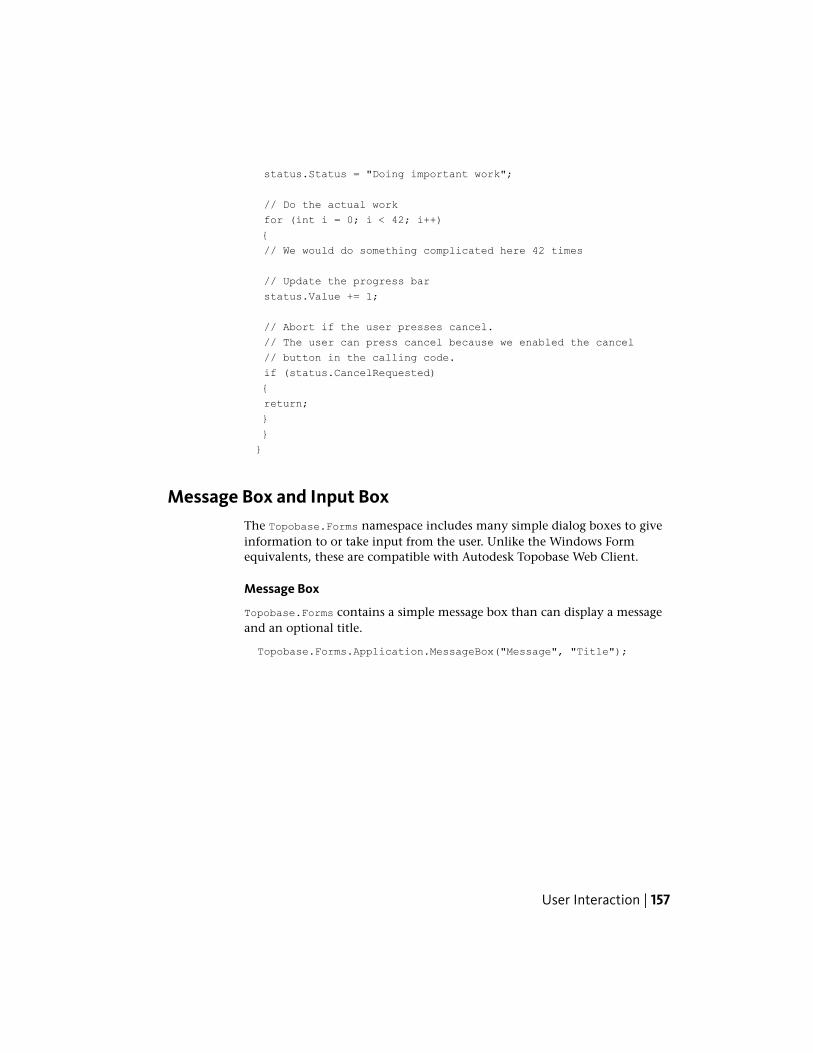
status.Status = "Doing important work";
// Do the actual work
for (int i = 0; i < 42; i++)
{
// We would do something complicated here 42 times
// Update the progress bar
status.Value += 1;
// Abort if the user presses cancel.
// The user can press cancel because we enabled the cancel
// button in the calling code.
if (status.CancelRequested)
{
return;
}
}
}
Message Box and Input BoxThe Topobase.Forms namespace includes many simple dialog boxes to giveinformation to or take input from the user. Unlike the Windows Formequivalents, these are compatible with Autodesk Topobase Web Client.
Message Box
Topobase.Forms contains a simple message box than can display a messageand an optional title.
Topobase.Forms.Application.MessageBox("Message", "Title");
User Interaction | 157
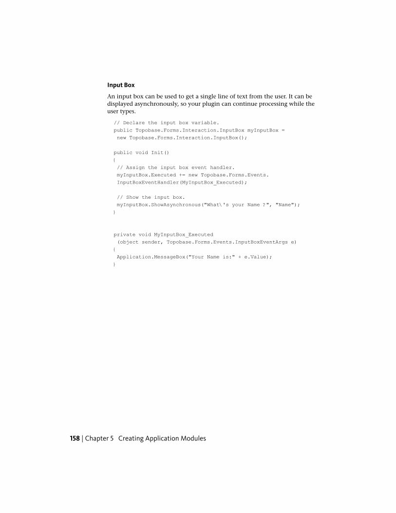
Input Box
An input box can be used to get a single line of text from the user. It can bedisplayed asynchronously, so your plugin can continue processing while theuser types.
// Declare the input box variable.
public Topobase.Forms.Interaction.InputBox myInputBox =
new Topobase.Forms.Interaction.InputBox();
public void Init()
{
// Assign the input box event handler.
myInputBox.Executed += new Topobase.Forms.Events.
InputBoxEventHandler(MyInputBox_Executed);
// Show the input box.
myInputBox.ShowAsynchronous("What\'s your Name ?", "Name");
}
private void MyInputBox_Executed
(object sender, Topobase.Forms.Events.InputBoxEventArgs e)
{
Application.MessageBox("Your Name is:" + e.Value);
}
158 | Chapter 5 Creating Application Modules
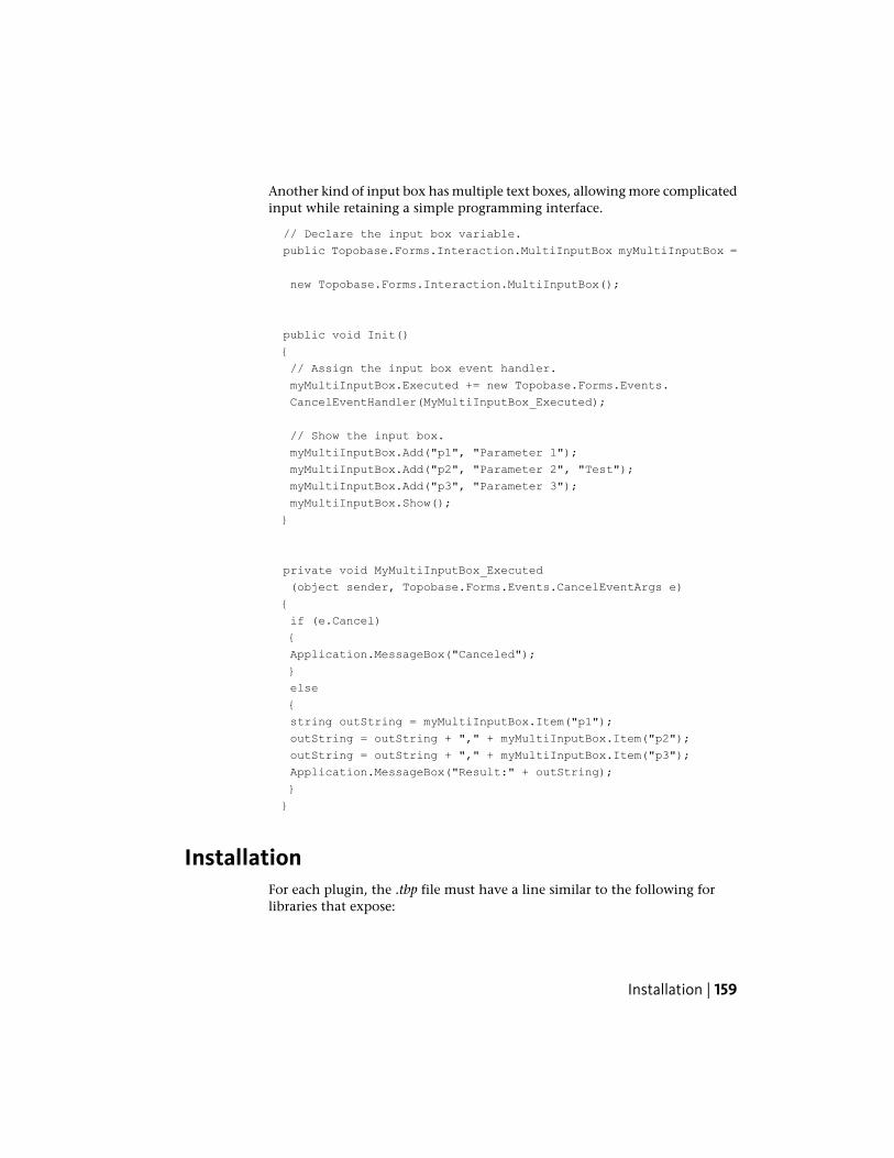
Another kind of input box has multiple text boxes, allowing more complicatedinput while retaining a simple programming interface.
// Declare the input box variable.
public Topobase.Forms.Interaction.MultiInputBox myMultiInputBox =
new Topobase.Forms.Interaction.MultiInputBox();
public void Init()
{
// Assign the input box event handler.
myMultiInputBox.Executed += new Topobase.Forms.Events.
CancelEventHandler(MyMultiInputBox_Executed);
// Show the input box.
myMultiInputBox.Add("p1", "Parameter 1");
myMultiInputBox.Add("p2", "Parameter 2", "Test");
myMultiInputBox.Add("p3", "Parameter 3");
myMultiInputBox.Show();
}
private void MyMultiInputBox_Executed
(object sender, Topobase.Forms.Events.CancelEventArgs e)
{
if (e.Cancel)
{
Application.MessageBox("Canceled");
}
else
{
string outString = myMultiInputBox.Item("p1");
outString = outString + "," + myMultiInputBox.Item("p2");
outString = outString + "," + myMultiInputBox.Item("p3");
Application.MessageBox("Result:" + outString);
}
}
InstallationFor each plugin, the .tbp file must have a line similar to the following forlibraries that expose:
Installation | 159
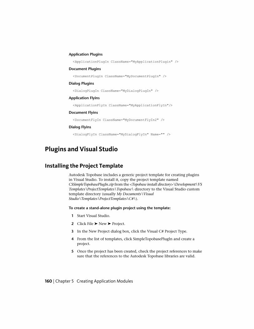
Application Plugins
<ApplicationPlugIn ClassName="MyApplicationPlugin" />
Document Plugins
<DocumentPlugIn ClassName="MyDocumentPlugIn" />
Dialog Plugins
<DialogPlugIn ClassName="MyDialogPlugIn" />
Application Flyins
<ApplicationFlyIn ClassName="MyApplicationFlyIn"/>
Document Flyins
<DocumentFlyIn ClassName="MyDocumentFlyIn2" />
Dialog Flyins
<DialogFlyIn ClassName="MyDialogFlyIn" Name="" />
Plugins and Visual Studio
Installing the Project TemplateAutodesk Topobase includes a generic project template for creating pluginsin Visual Studio. To install it, copy the project template namedCSSimpleTopobasePlugIn.zip from the <Topobase install directory>\Development\VSTemplates\ProjectTemplates\Topobase\ directory to the Visual Studio customtemplate directory (usually My Documents\VisualStudio\Templates\ProjectTemplates\C#\).
To create a stand-alone plugin project using the template:
1 Start Visual Studio.
2 Click File ➤ New ➤ Project.
3 In the New Project dialog box, click the Visual C# Project Type.
4 From the list of templates, click SimpleTopobasePlugIn and create aproject.
5 Once the project has been created, check the project references to makesure that the references to the Autodesk Topobase libraries are valid.
160 | Chapter 5 Creating Application Modules
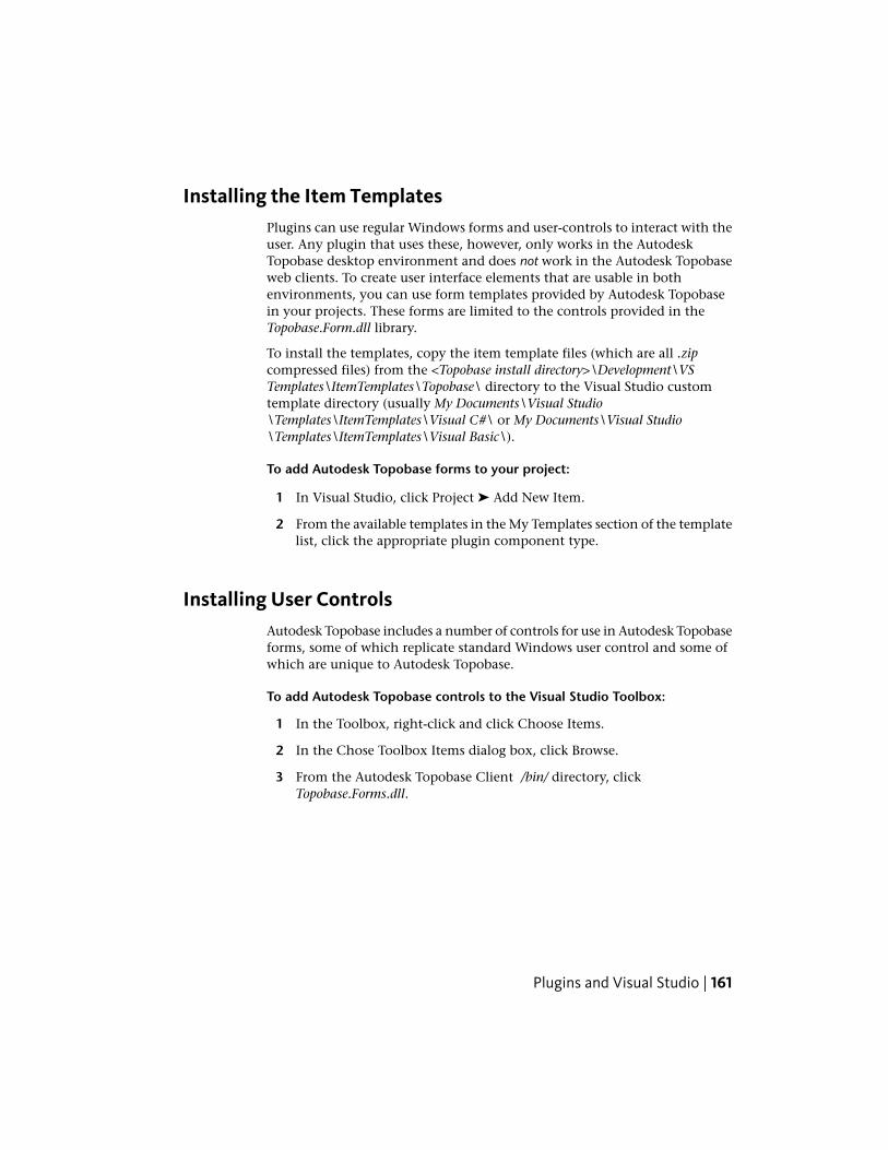
Installing the Item TemplatesPlugins can use regular Windows forms and user-controls to interact with theuser. Any plugin that uses these, however, only works in the AutodeskTopobase desktop environment and does not work in the Autodesk Topobaseweb clients. To create user interface elements that are usable in bothenvironments, you can use form templates provided by Autodesk Topobasein your projects. These forms are limited to the controls provided in theTopobase.Form.dll library.
To install the templates, copy the item template files (which are all .zipcompressed files) from the <Topobase install directory>\Development\VSTemplates\ItemTemplates\Topobase\ directory to the Visual Studio customtemplate directory (usually My Documents\Visual Studio\Templates\ItemTemplates\Visual C#\ or My Documents\Visual Studio\Templates\ItemTemplates\Visual Basic\).
To add Autodesk Topobase forms to your project:
1 In Visual Studio, click Project ➤ Add New Item.
2 From the available templates in the My Templates section of the templatelist, click the appropriate plugin component type.
Installing User ControlsAutodesk Topobase includes a number of controls for use in Autodesk Topobaseforms, some of which replicate standard Windows user control and some ofwhich are unique to Autodesk Topobase.
To add Autodesk Topobase controls to the Visual Studio Toolbox:
1 In the Toolbox, right-click and click Choose Items.
2 In the Chose Toolbox Items dialog box, click Browse.
3 From the Autodesk Topobase Client /bin/ directory, clickTopobase.Forms.dll.
Plugins and Visual Studio | 161
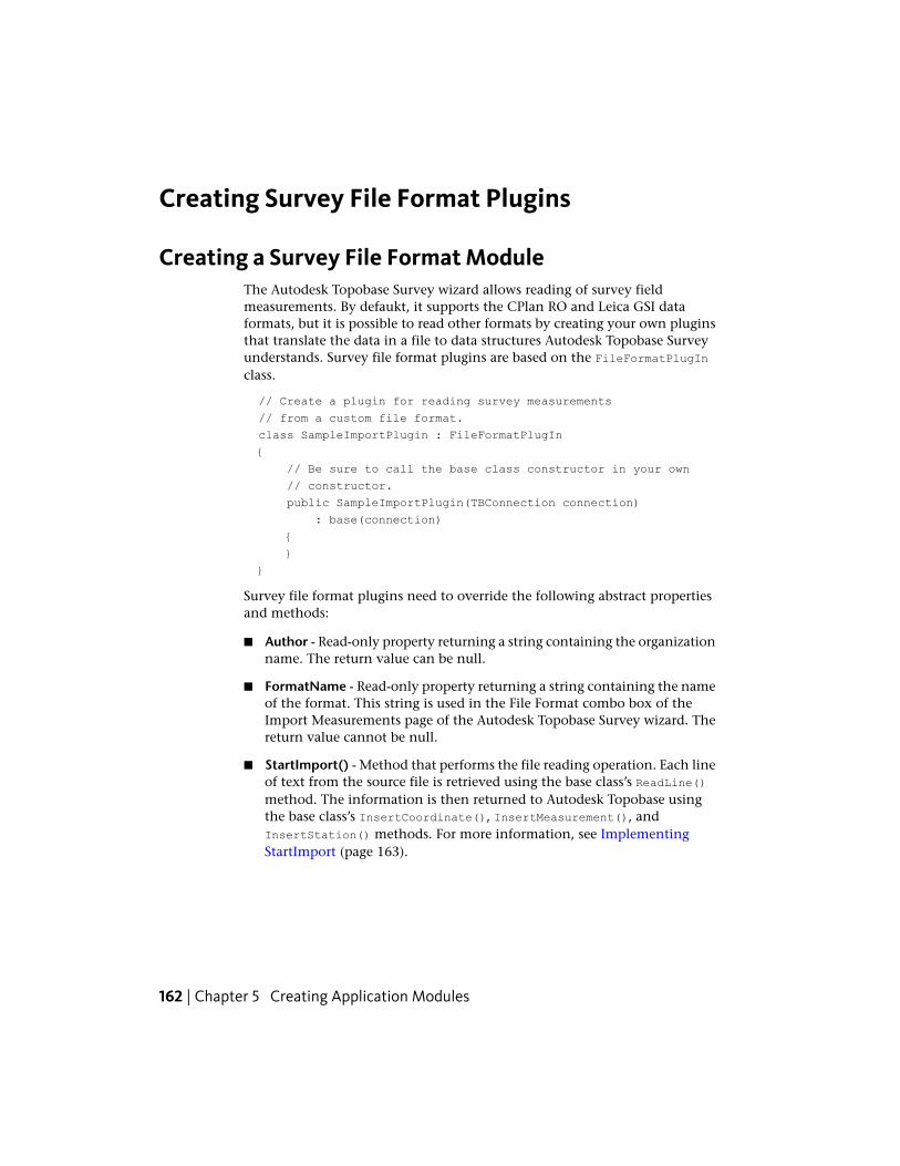
Creating Survey File Format Plugins
Creating a Survey File Format ModuleThe Autodesk Topobase Survey wizard allows reading of survey fieldmeasurements. By defaukt, it supports the CPlan RO and Leica GSI dataformats, but it is possible to read other formats by creating your own pluginsthat translate the data in a file to data structures Autodesk Topobase Surveyunderstands. Survey file format plugins are based on the FileFormatPlugInclass.
// Create a plugin for reading survey measurements
// from a custom file format.
class SampleImportPlugin : FileFormatPlugIn
{
// Be sure to call the base class constructor in your own
// constructor.
public SampleImportPlugin(TBConnection connection)
: base(connection)
{
}
}
Survey file format plugins need to override the following abstract propertiesand methods:
■ Author - Read-only property returning a string containing the organizationname. The return value can be null.
■ FormatName - Read-only property returning a string containing the nameof the format. This string is used in the File Format combo box of theImport Measurements page of the Autodesk Topobase Survey wizard. Thereturn value cannot be null.
■ StartImport() - Method that performs the file reading operation. Each lineof text from the source file is retrieved using the base class’s ReadLine()method. The information is then returned to Autodesk Topobase usingthe base class’s InsertCoordinate(), InsertMeasurement(), andInsertStation() methods. For more information, see ImplementingStartImport (page 163).
162 | Chapter 5 Creating Application Modules
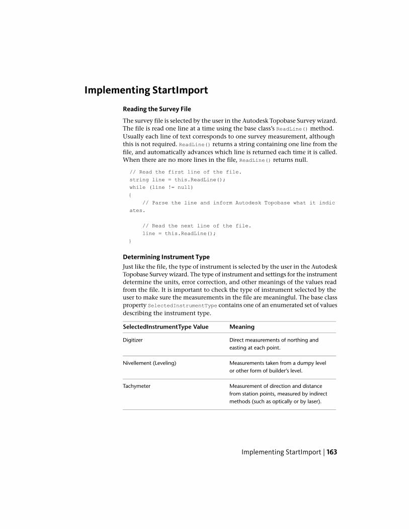
Implementing StartImport
Reading the Survey File
The survey file is selected by the user in the Autodesk Topobase Survey wizard.The file is read one line at a time using the base class’s ReadLine() method.Usually each line of text corresponds to one survey measurement, althoughthis is not required. ReadLine() returns a string containing one line from thefile, and automatically advances which line is returned each time it is called.When there are no more lines in the file, ReadLine() returns null.
// Read the first line of the file.
string line = this.ReadLine();
while (line != null)
{
// Parse the line and inform Autodesk Topobase what it indic
ates.
// Read the next line of the file.
line = this.ReadLine();
}
Determining Instrument TypeJust like the file, the type of instrument is selected by the user in the AutodeskTopobase Survey wizard. The type of instrument and settings for the instrumentdetermine the units, error correction, and other meanings of the values readfrom the file. It is important to check the type of instrument selected by theuser to make sure the measurements in the file are meaningful. The base classproperty SelectedInstrumentType contains one of an enumerated set of valuesdescribing the instrument type.
MeaningSelectedInstrumentType Value
Direct measurements of northing andeasting at each point.
Digitizer
Measurements taken from a dumpy levelor other form of builder’s level.
Nivellement (Leveling)
Measurement of direction and distancefrom station points, measured by indirectmethods (such as optically or by laser).
Tachymeter
Implementing StartImport | 163
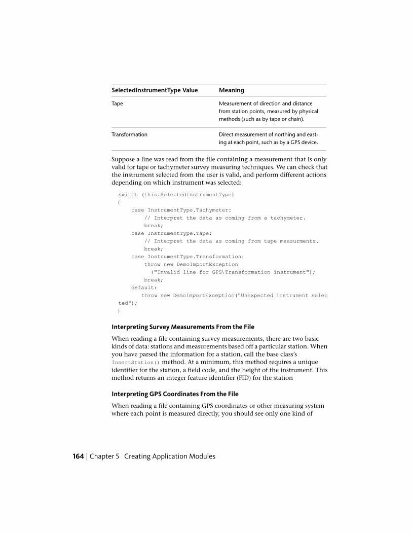
MeaningSelectedInstrumentType Value
Measurement of direction and distancefrom station points, measured by physicalmethods (such as by tape or chain).
Tape
Direct measurement of northing and east-ing at each point, such as by a GPS device.
Transformation
Suppose a line was read from the file containing a measurement that is onlyvalid for tape or tachymeter survey measuring techniques. We can check thatthe instrument selected from the user is valid, and perform different actionsdepending on which instrument was selected:
switch (this.SelectedInstrumentType)
{
case InstrumentType.Tachymeter:
// Interpret the data as coming from a tachymeter.
break;
case InstrumentType.Tape:
// Interpret the data as coming from tape measurments.
break;
case InstrumentType.Transformation:
throw new DemoImportException
("Invalid line for GPS\Transformation instrument");
break;
default:
throw new DemoImportException("Unexpected instrument selec
ted");
}
Interpreting Survey Measurements From the File
When reading a file containing survey measurements, there are two basickinds of data: stations and measurements based off a particular station. Whenyou have parsed the information for a station, call the base class’sInsertStation() method. At a minimum, this method requires a uniqueidentifier for the station, a field code, and the height of the instrument. Thismethod returns an integer feature identifier (FID) for the station
Interpreting GPS Coordinates From the File
When reading a file containing GPS coordinates or other measuring systemwhere each point is measured directly, you should see only one kind of
164 | Chapter 5 Creating Application Modules
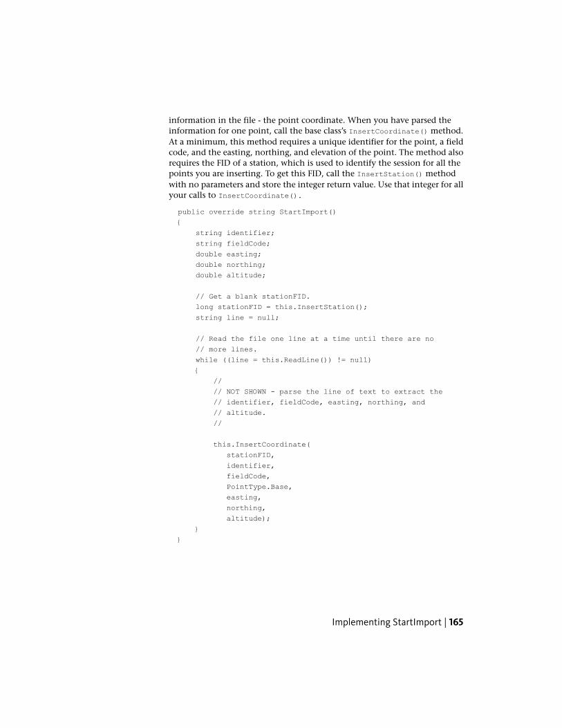
information in the file - the point coordinate. When you have parsed theinformation for one point, call the base class’s InsertCoordinate() method.At a minimum, this method requires a unique identifier for the point, a fieldcode, and the easting, northing, and elevation of the point. The method alsorequires the FID of a station, which is used to identify the session for all thepoints you are inserting. To get this FID, call the InsertStation() methodwith no parameters and store the integer return value. Use that integer for allyour calls to InsertCoordinate().
public override string StartImport()
{
string identifier;
string fieldCode;
double easting;
double northing;
double altitude;
// Get a blank stationFID.
long stationFID = this.InsertStation();
string line = null;
// Read the file one line at a time until there are no
// more lines.
while ((line = this.ReadLine()) != null)
{
//
// NOT SHOWN - parse the line of text to extract the
// identifier, fieldCode, easting, northing, and
// altitude.
//
this.InsertCoordinate(
stationFID,
identifier,
fieldCode,
PointType.Base,
easting,
northing,
altitude);
}
}
Implementing StartImport | 165
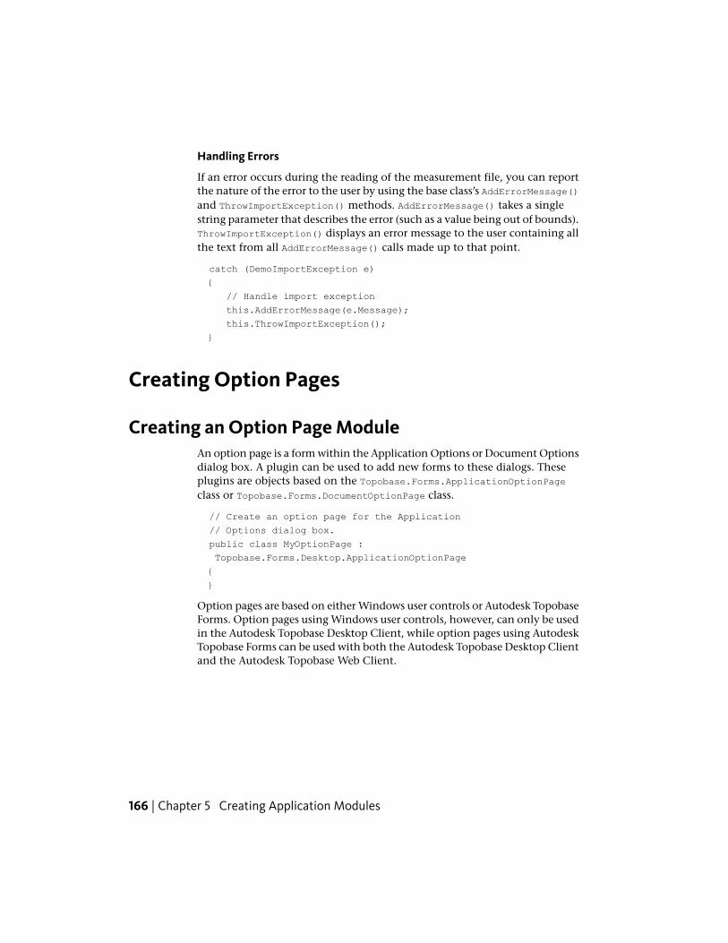
Handling Errors
If an error occurs during the reading of the measurement file, you can reportthe nature of the error to the user by using the base class’s AddErrorMessage()and ThrowImportException() methods. AddErrorMessage() takes a singlestring parameter that describes the error (such as a value being out of bounds).ThrowImportException() displays an error message to the user containing allthe text from all AddErrorMessage() calls made up to that point.
catch (DemoImportException e)
{
// Handle import exception
this.AddErrorMessage(e.Message);
this.ThrowImportException();
}
Creating Option Pages
Creating an Option Page ModuleAn option page is a form within the Application Options or Document Optionsdialog box. A plugin can be used to add new forms to these dialogs. Theseplugins are objects based on the Topobase.Forms.ApplicationOptionPageclass or Topobase.Forms.DocumentOptionPage class.
// Create an option page for the Application
// Options dialog box.
public class MyOptionPage :
Topobase.Forms.Desktop.ApplicationOptionPage
{
}
Option pages are based on either Windows user controls or Autodesk TopobaseForms. Option pages using Windows user controls, however, can only be usedin the Autodesk Topobase Desktop Client, while option pages using AutodeskTopobase Forms can be used with both the Autodesk Topobase Desktop Clientand the Autodesk Topobase Web Client.
166 | Chapter 5 Creating Application Modules
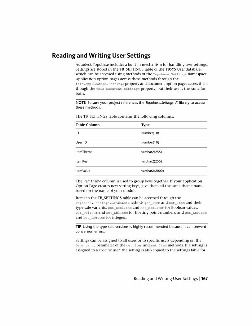
Reading and Writing User SettingsAutodesk Topobase includes a built-in mechanism for handling user settings.Settings are stored in the TB_SETTINGS table of the TBSYS User database,which can be accessed using methods of the Topobase.Settings namespace.Application option pages access these methods through thethis.Application.Settings property and document option pages access themthough the this.Document.Settings property, but their use is the same forboth.
NOTE Be sure your project references the Topobase.Settings.dll library to accessthese methods.
The TB_SETTINGS table contains the following columns:
TypeTable Column
number(10)ID
number(10)User_ID
varchar2(255)ItemThema
varchar2(255)ItemKey
varchar2(2000)ItemValue
The ItemThema column is used to group keys together. If your applicationOption Page creates new setting keys, give them all the same theme namebased on the name of your module.
Items in the TB_SETTINGS table can be accessed through theTopobase.Settings.Database methods get_Item and set_Item and theirtype-safe variants, get_BoolItem and set_BoolItem for Boolean values,get_DblItem and set_DblItem for floating point numbers, and get_LngItemand set_LngItem for integers.
TIP Using the type-safe versions is highly recommended because it can preventconversion errors.
Settings can be assigned to all users or to specific users depending on theDependency parameter of the get_Item and set_Item methods. If a setting isassigned to a specific user, the setting is also copied to the settings table for
Reading and Writing User Settings | 167

all users. This serves as a default value if you attempt to read specific usersettings that have not yet been set.
The following sample demonstrates reading and writing user settings. It isbased on a Autodesk Topobase Form with two textbox controls. When theform is first displayed, it accesses the existing settings and displays them in
168 | Chapter 5 Creating Application Modules

the textboxes. When the user closes the option page dialog box, the settingsare saved.
Reading and Writing User Settings | 169
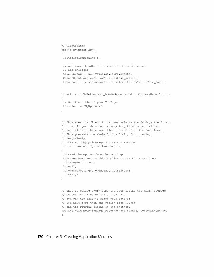
// Constructor.
public MyOptionPage()
{
InitializeComponent();
// Add event handlers for when the form is loaded
// and unloaded.
this.Unload += new Topobase.Forms.Events.
UnloadEventHandler(this.MyOptionPage_Unload);
this.Load += new System.EventHandler(this.MyOptionPage_Load);
}
private void MyOptionPage_Load(object sender, System.EventArgs e)
{
// Set the title of your TabPage.
this.Text = "MyOptions";
}
// This event is fired if the user selects the TabPage the first
// time. If your data took a very long time to initialize,
// initialize it here next time instead of at the Load Event.
// This prevents the whole Option Dialog from opening
// very slowly.
private void MyOptionPage_ActivatedFirstTime
(object sender, System.EventArgs e)
{
// Read the option from the settings.
this.TextBox1.Text = this.Application.Settings.get_Item
("CSSampleOptions",
"Name1",
Topobase.Settings.Dependency.CurrentUser,
"Test1");
}
// This is called every time the user clicks the Main TreeNode
// on the Left Tree of the Option Page.
// You can use this to reset your data if
// you have more than one Option Page Plugin,
// and the Plugins depend on one another.
private void MyOptionPage_Reset(object sender, System.EventArgs
e)
170 | Chapter 5 Creating Application Modules
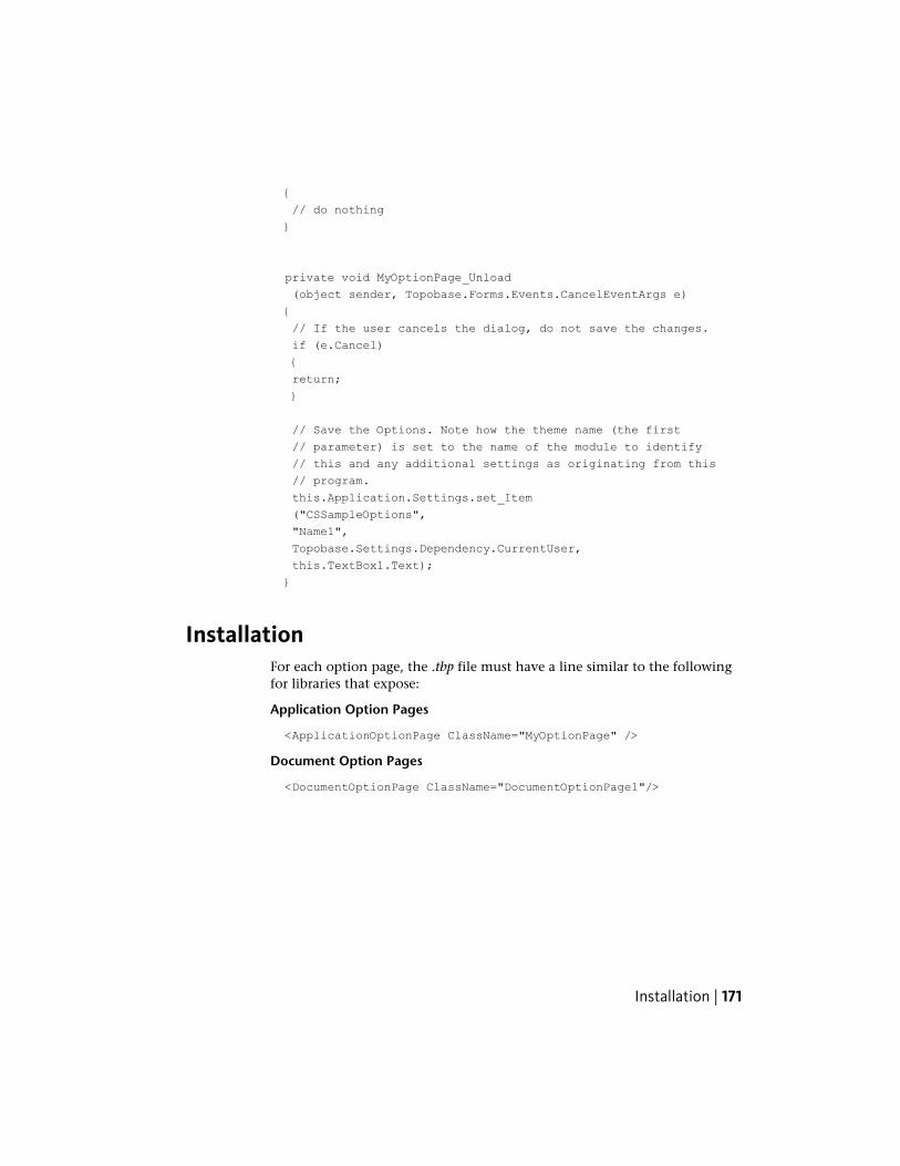
{
// do nothing
}
private void MyOptionPage_Unload
(object sender, Topobase.Forms.Events.CancelEventArgs e)
{
// If the user cancels the dialog, do not save the changes.
if (e.Cancel)
{
return;
}
// Save the Options. Note how the theme name (the first
// parameter) is set to the name of the module to identify
// this and any additional settings as originating from this
// program.
this.Application.Settings.set_Item
("CSSampleOptions",
"Name1",
Topobase.Settings.Dependency.CurrentUser,
this.TextBox1.Text);
}
InstallationFor each option page, the .tbp file must have a line similar to the followingfor libraries that expose:
Application Option Pages
<ApplicationOptionPage ClassName="MyOptionPage" />
Document Option Pages
<DocumentOptionPage ClassName="DocumentOptionPage1"/>
Installation | 171
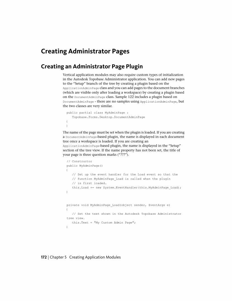
Creating Administrator Pages
Creating an Administrator Page PluginVertical application modules may also require custom types of initializationin the Autodesk Topobase Administrator application. You can add new pagesto the “Setup” branch of the tree by creating a plugin based on theApplicationAdminPage class and you can add pages to the document branches(which are visible only after loading a workspace) by creating a plugin basedon the DocumentAdminPage class. Sample 122 includes a plugin based onDocumentAdminPage - there are no samples using ApplicationAdminPage, butthe two classes are very similar.
public partial class MyAdminPage :
Topobase.Forms.Desktop.DocumentAdminPage
{
}
The name of the page must be set when the plugin is loaded. If you are creatinga DocumentAdminPage-based plugin, the name is displayed in each documenttree once a workspace is loaded. If you are creating anApplicationAdminPage-based plugin, the name is displayed in the “Setup”section of the tree view. If the name property has not been set, the title ofyour page is three question marks (“???”).
// Constructor
public MyAdminPage()
{
// Set up the event handler for the Load event so that the
// function MyAdminPage_Load is called when the plugin
// is first loaded.
this.Load += new System.EventHandler(this.MyAdminPage_Load);
}
private void MyAdminPage_Load(object sender, EventArgs e)
{
// Set the text shown in the Autodesk Topobase Administrator
tree view.
this.Text = "My Custom Admin Page";
}
172 | Chapter 5 Creating Application Modules
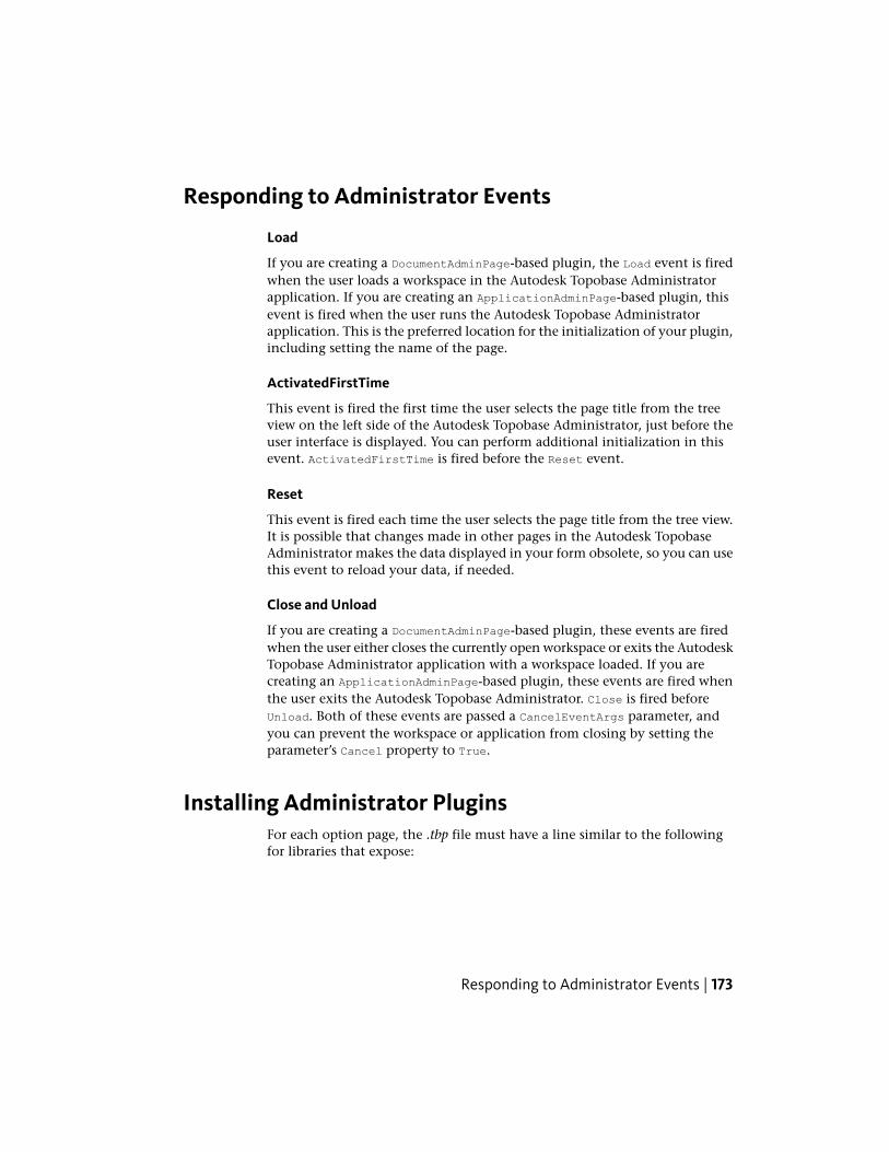
Responding to Administrator Events
Load
If you are creating a DocumentAdminPage-based plugin, the Load event is firedwhen the user loads a workspace in the Autodesk Topobase Administratorapplication. If you are creating an ApplicationAdminPage-based plugin, thisevent is fired when the user runs the Autodesk Topobase Administratorapplication. This is the preferred location for the initialization of your plugin,including setting the name of the page.
ActivatedFirstTime
This event is fired the first time the user selects the page title from the treeview on the left side of the Autodesk Topobase Administrator, just before theuser interface is displayed. You can perform additional initialization in thisevent. ActivatedFirstTime is fired before the Reset event.
Reset
This event is fired each time the user selects the page title from the tree view.It is possible that changes made in other pages in the Autodesk TopobaseAdministrator makes the data displayed in your form obsolete, so you can usethis event to reload your data, if needed.
Close and Unload
If you are creating a DocumentAdminPage-based plugin, these events are firedwhen the user either closes the currently open workspace or exits the AutodeskTopobase Administrator application with a workspace loaded. If you arecreating an ApplicationAdminPage-based plugin, these events are fired whenthe user exits the Autodesk Topobase Administrator. Close is fired beforeUnload. Both of these events are passed a CancelEventArgs parameter, andyou can prevent the workspace or application from closing by setting theparameter’s Cancel property to True.
Installing Administrator PluginsFor each option page, the .tbp file must have a line similar to the followingfor libraries that expose:
Responding to Administrator Events | 173
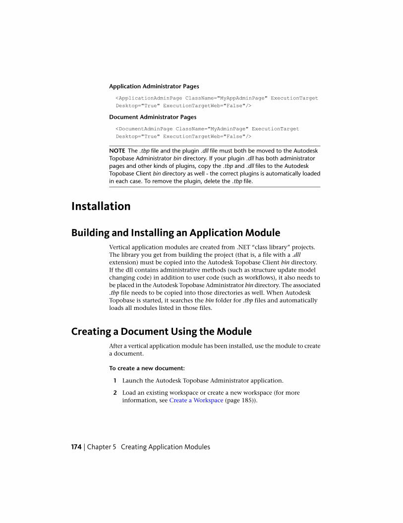
Application Administrator Pages
<ApplicationAdminPage ClassName="MyAppAdminPage" ExecutionTarget
Desktop="True" ExecutionTargetWeb="False"/>
Document Administrator Pages
<DocumentAdminPage ClassName="MyAdminPage" ExecutionTarget
Desktop="True" ExecutionTargetWeb="False"/>
NOTE The .tbp file and the plugin .dll file must both be moved to the AutodeskTopobase Administrator bin directory. If your plugin .dll has both administratorpages and other kinds of plugins, copy the .tbp and .dll files to the AutodeskTopobase Client bin directory as well - the correct plugins is automatically loadedin each case. To remove the plugin, delete the .tbp file.
Installation
Building and Installing an Application ModuleVertical application modules are created from .NET “class library” projects.The library you get from building the project (that is, a file with a .dllextension) must be copied into the Autodesk Topobase Client bin directory.If the dll contains administrative methods (such as structure update modelchanging code) in addition to user code (such as workflows), it also needs tobe placed in the Autodesk Topobase Administrator bin directory. The associated.tbp file needs to be copied into those directories as well. When AutodeskTopobase is started, it searches the bin folder for .tbp files and automaticallyloads all modules listed in those files.
Creating a Document Using the ModuleAfter a vertical application module has been installed, use the module to createa document.
To create a new document:
1 Launch the Autodesk Topobase Administrator application.
2 Load an existing workspace or create a new workspace (for moreinformation, see Create a Workspace (page 185)).
174 | Chapter 5 Creating Application Modules
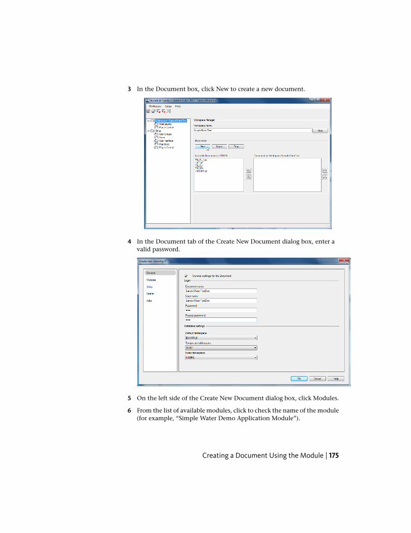
3 In the Document box, click New to create a new document.
4 In the Document tab of the Create New Document dialog box, enter avalid password.
5 On the left side of the Create New Document dialog box, click Modules.
6 From the list of available modules, click to check the name of the module(for example, “Simple Water Demo Application Module”).
Creating a Document Using the Module | 175
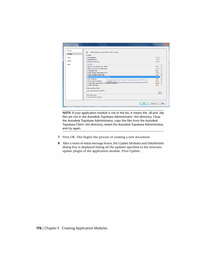
NOTE If your application module is not in the list, it means the .dll and .tbpfiles are not in the Autodesk Topobase Administrator \bin directory. Closethe Autodesk Topobase Administrator, copy the files from the AutodeskTopobase Client \bin directory, restart the Autodesk Topobase Administrator,and try again.
7 Press OK. This begins the process of creating a new document.
8 After a series of status message boxes, the Update Modules and DataModelsdialog box is displayed listing all the updates specified in the structureupdate plugin of the application module. Press Update.
176 | Chapter 5 Creating Application Modules
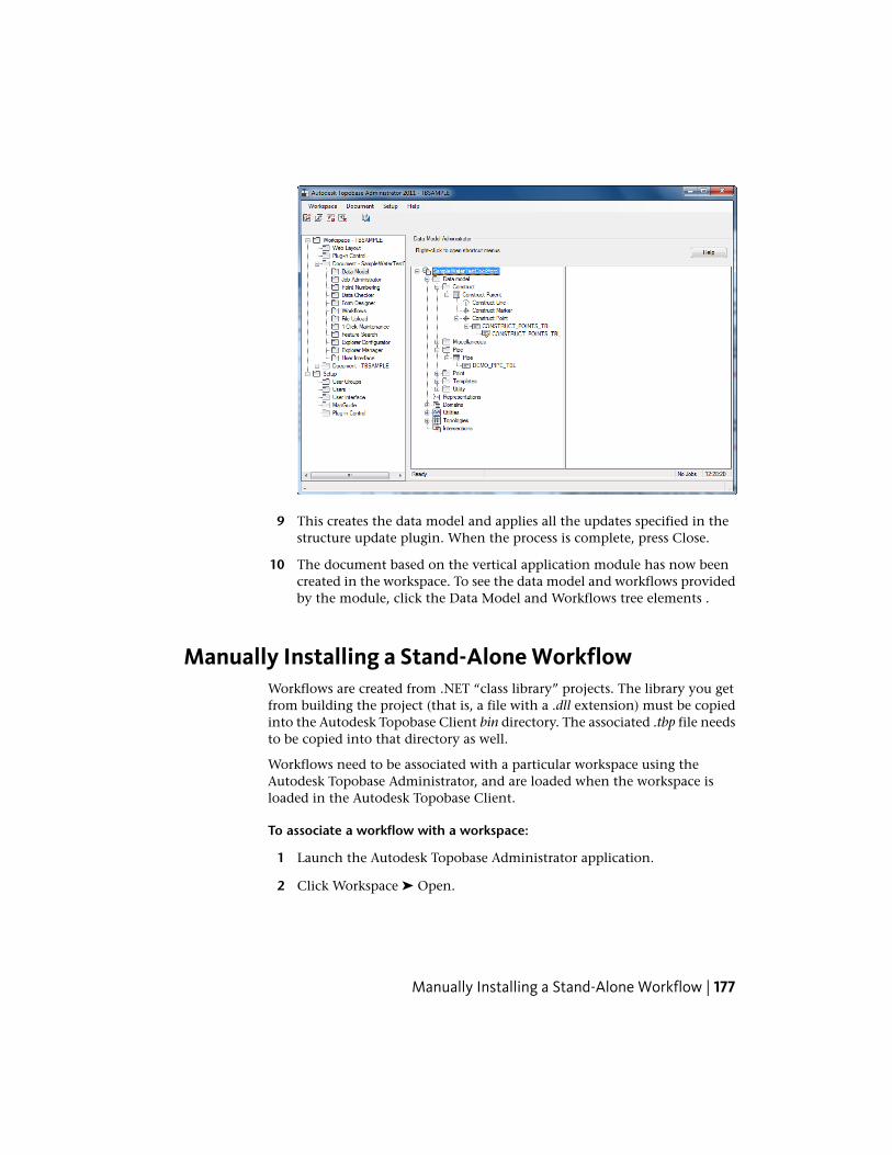
9 This creates the data model and applies all the updates specified in thestructure update plugin. When the process is complete, press Close.
10 The document based on the vertical application module has now beencreated in the workspace. To see the data model and workflows providedby the module, click the Data Model and Workflows tree elements .
Manually Installing a Stand-Alone WorkflowWorkflows are created from .NET “class library” projects. The library you getfrom building the project (that is, a file with a .dll extension) must be copiedinto the Autodesk Topobase Client bin directory. The associated .tbp file needsto be copied into that directory as well.
Workflows need to be associated with a particular workspace using theAutodesk Topobase Administrator, and are loaded when the workspace isloaded in the Autodesk Topobase Client.
To associate a workflow with a workspace:
1 Launch the Autodesk Topobase Administrator application.
2 Click Workspace ➤ Open.
Manually Installing a Stand-Alone Workflow | 177
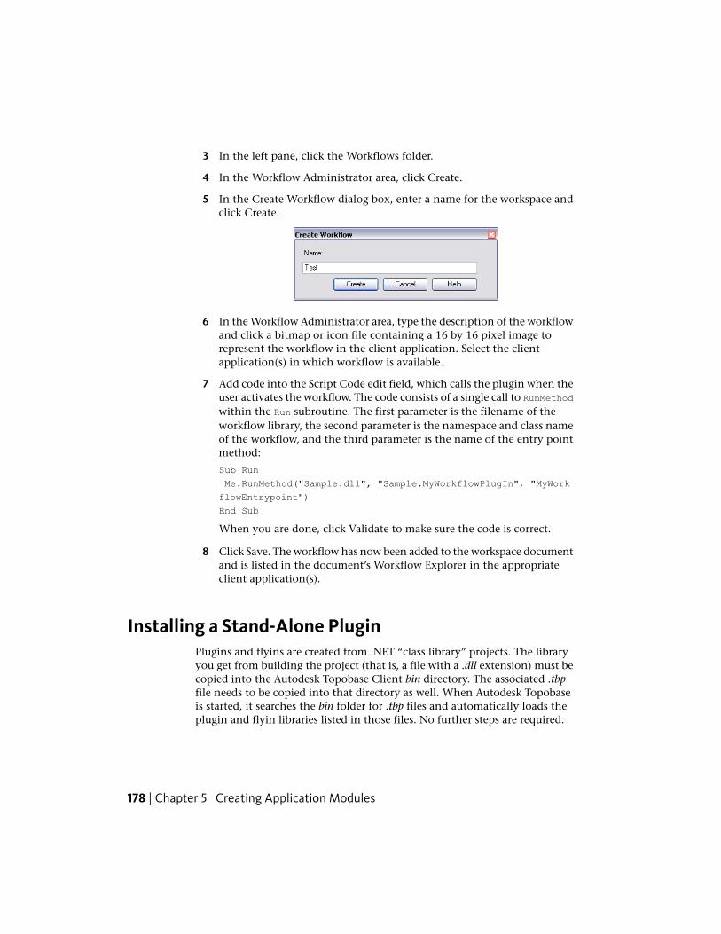
3 In the left pane, click the Workflows folder.
4 In the Workflow Administrator area, click Create.
5 In the Create Workflow dialog box, enter a name for the workspace andclick Create.
6 In the Workflow Administrator area, type the description of the workflowand click a bitmap or icon file containing a 16 by 16 pixel image torepresent the workflow in the client application. Select the clientapplication(s) in which workflow is available.
7 Add code into the Script Code edit field, which calls the plugin when theuser activates the workflow. The code consists of a single call to RunMethodwithin the Run subroutine. The first parameter is the filename of theworkflow library, the second parameter is the namespace and class nameof the workflow, and the third parameter is the name of the entry pointmethod:
Sub Run
Me.RunMethod("Sample.dll", "Sample.MyWorkflowPlugIn", "MyWork
flowEntrypoint")
End Sub
When you are done, click Validate to make sure the code is correct.
8 Click Save. The workflow has now been added to the workspace documentand is listed in the document’s Workflow Explorer in the appropriateclient application(s).
Installing a Stand-Alone PluginPlugins and flyins are created from .NET “class library” projects. The libraryyou get from building the project (that is, a file with a .dll extension) must becopied into the Autodesk Topobase Client bin directory. The associated .tbpfile needs to be copied into that directory as well. When Autodesk Topobaseis started, it searches the bin folder for .tbp files and automatically loads theplugin and flyin libraries listed in those files. No further steps are required.
178 | Chapter 5 Creating Application Modules
Developer Samples
IntroductionAutodesk® Topobase™ provides over 80 samples showing how you can use theAPI. These are provided in both Visual Basic and C# formats. They cover a broadrange of categories, such as creating users, connecting to the database,customizing the user interface, and manipulating features.
This chapter describes how to build, install, and run the samples, and gives abrief description of what they do. For more details, see the sample code itself.The sample code is installed into <topobase>\Development\Samples where<topobase> is the Autodesk Topobase installation directory. This is typicallyC:\Program Files\Autodesk Topobase Client <yyyy>, where <yyyy> is the productversion.
NOTE The samples are numbered, but since obsolete samples have been removedthe numbers are not always consecutive.
Most of the samples use a Autodesk Topobase plugin configuration file (.tbp).For more information, see Quick Guide: Creating a Topobase Plugin (page75)TBP File Format (page 353) and TBP File Format (page 353)
IMPORTANT Most of the samples can be run independently. However, some ofthem use the required features and workspace set up by Sample 01 so you MUSTbuild and run Sample 01 first. See Sample 01 - Create Structure (page 182) fordetails.
Some of the samples require the use of a workspace more fully featured that theone setup by Sample 01. The workspace referred to here is the demo LandManagement workspace (TB_LM_WA) whose creation is described in the Setting
6
179
up the Demo Data topic in the Getting Started section of the Autodesk TopobaseAdministrator Guide.
Unless otherwise stated, all the samples can be run in either the desktopAutodesk Topobase Client or Autodesk Topobase Web Client.
Building The SamplesWhen configured appropriately (see Configuring the Project to Write the BuildOutputs to the Topobase Bin Folder (page 78)), during each sample build therequired output files are copied to the Autodesk Topobase bin folder (that is,the required .dll, .xml, .pdb, .tbp, and/or .exe are copied). For more detailedinformation about each of the samples, see the Common Steps (page 181) andSample Details (page 182) sections for each sample.
Usernames and PasswordsIf you are not using the default Oracle© service name orcl, or AutodeskTopobase system username TBSYS and password TBSYS, you must change themin all lines as follows:
Topobase.Data.TBConnection myConnection = new Topobase.Data.TBCon
nection("TBSample", "avs", "orcl", true, "TBSYS", "TBSYS", "orcl");
TIP The user with username TBSample and password avs is created by Sample01 and is used in several other samples.
Topobase Database Server (TBSYS)The Autodesk Topobase database server TBSYS can be installed on the samecomputer as the Autodesk Topobase Client version or on a separate databaseserver. Use the Autodesk Topobase Server Administrator to install the AutodeskTopobase server.
For more information about installing TBSYS, see the Setting up the Databasetopic in the Getting Started section in Autodesk Topobase Administrator Guide.
180 | Chapter 6 Developer Samples
Running The SamplesSample 01 - Create Structure (page 182) needs to be built and run first to createthe TBSAMPLE workspace (see Create a Workspace (page 185).)
Create a Drawing Template (page 187) is also a required procedure to createthe TBSAMPLE drawing table. The steps are documented at the end of Sample01.
Common StepsThere are some steps that are required for running all of the samples:
1 Build the sample.
The build process automatically places the program or plugin into thebin folder. If you move the project from the Autodesk TopobaseDevelopment\Samples folder, be sure to change the project output pathso that the executable is placed in the correct location (the output pathis adjusted in the Build tab of the project properties in Visual Studio). Forprojects that create a plugin, the associated .tbp file is also automaticallycopied to the Autodesk Topobase Client bin folder. For more informationabout .tbp files, see Quick Guide: Creating a Topobase Plugin (page 75)and TBP File Format (page 353)
2 Run the sample.
For applications, run the executable in the Autodesk Topobase bin folder.For plugins, start Autodesk Topobase, connect to the database, and opena workspace. This triggers the loading of the plugins.
To disable a plugin, remove the sample’s .dll and .tbp files from the bin folderand close the current workspace. Remove any .xml and .pdb files associatedwith the project as well.
NOTE Unless otherwise noted, menu references (for example, clickWorkspace ➤ Create) refer to the menu in the Autodesk Topobase task pane.
Running The Samples | 181
Sample Details
Sample 01 - Create Structure
WARNING The workspace and feature classes in Sample 01 are required in someof the other samples, so building and running Sample 01 is a prerequisite.
PurposeThis sample shows how to:
■ Create a new database (Oracle) user
■ Connect to a database
■ Create feature classes
■ Get information about feature classes
■ Delete feature classes
The workspace and feature classes created here are also used in some of theother samples.
ProcedureTo use this sample:
1 Build the sample. The plugin (VBSample01.dll or CSSample01.dll) and theassociated .tbp file are copied to the Autodesk Topobase Client bindirectory.
2 Start Autodesk Topobase Client.
3 Click the application toolbar button with the tooltip Sample 01 - CreateStructure. The sample’s dialog box is displayed.
182 | Chapter 6 Developer Samples
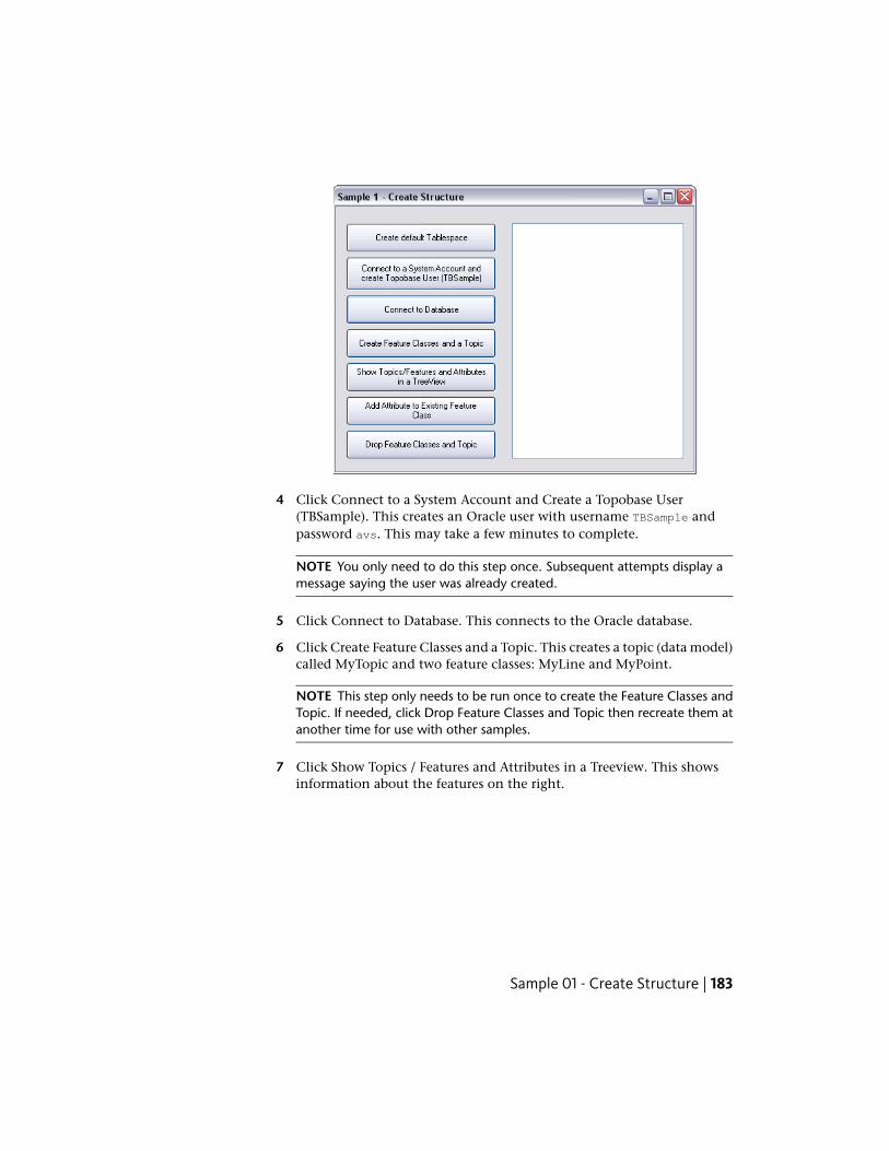
4 Click Connect to a System Account and Create a Topobase User(TBSample). This creates an Oracle user with username TBSample andpassword avs. This may take a few minutes to complete.
NOTE You only need to do this step once. Subsequent attempts display amessage saying the user was already created.
5 Click Connect to Database. This connects to the Oracle database.
6 Click Create Feature Classes and a Topic. This creates a topic (data model)called MyTopic and two feature classes: MyLine and MyPoint.
NOTE This step only needs to be run once to create the Feature Classes andTopic. If needed, click Drop Feature Classes and Topic then recreate them atanother time for use with other samples.
7 Click Show Topics / Features and Attributes in a Treeview. This showsinformation about the features on the right.
Sample 01 - Create Structure | 183
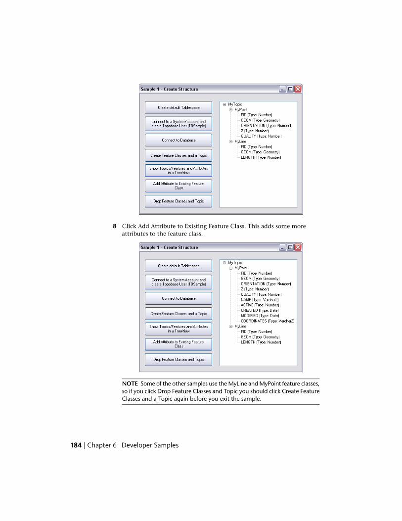
8 Click Add Attribute to Existing Feature Class. This adds some moreattributes to the feature class.
NOTE Some of the other samples use the MyLine and MyPoint feature classes,so if you click Drop Feature Classes and Topic you should click Create FeatureClasses and a Topic again before you exit the sample.
184 | Chapter 6 Developer Samples
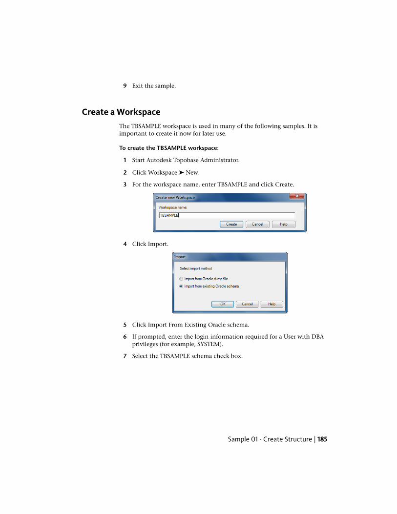
9 Exit the sample.
Create a WorkspaceThe TBSAMPLE workspace is used in many of the following samples. It isimportant to create it now for later use.
To create the TBSAMPLE workspace:
1 Start Autodesk Topobase Administrator.
2 Click Workspace ➤ New.
3 For the workspace name, enter TBSAMPLE and click Create.
4 Click Import.
5 Click Import From Existing Oracle schema.
6 If prompted, enter the login information required for a User with DBAprivileges (for example, SYSTEM).
7 Select the TBSAMPLE schema check box.
Sample 01 - Create Structure | 185
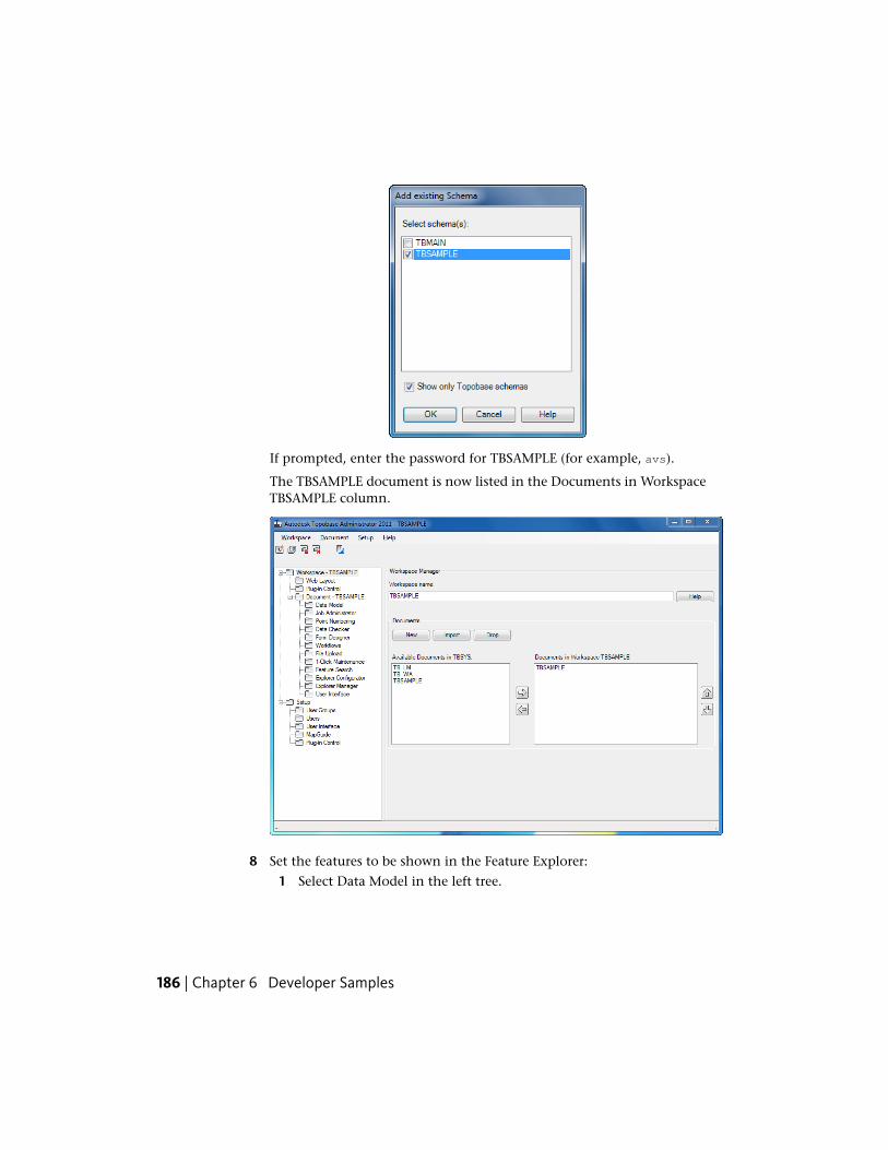
If prompted, enter the password for TBSAMPLE (for example, avs).
The TBSAMPLE document is now listed in the Documents in WorkspaceTBSAMPLE column.
8 Set the features to be shown in the Feature Explorer:
1 Select Data Model in the left tree.
186 | Chapter 6 Developer Samples
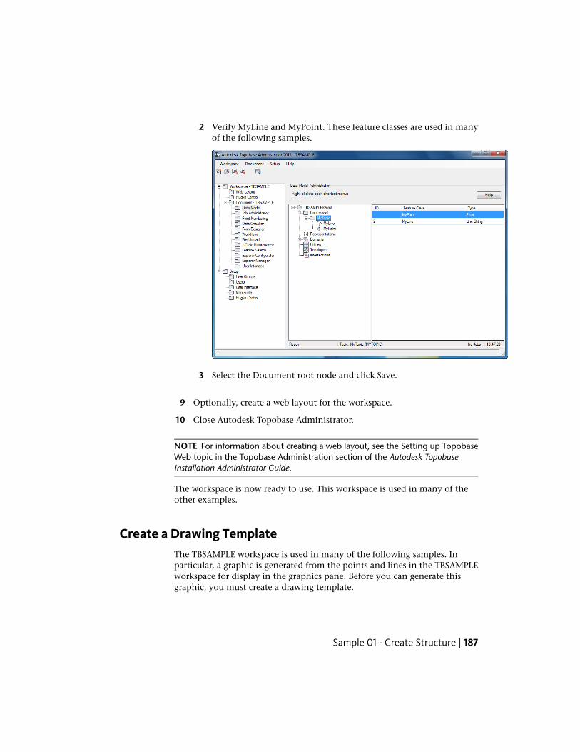
2 Verify MyLine and MyPoint. These feature classes are used in manyof the following samples.
3 Select the Document root node and click Save.
9 Optionally, create a web layout for the workspace.
10 Close Autodesk Topobase Administrator.
NOTE For information about creating a web layout, see the Setting up TopobaseWeb topic in the Topobase Administration section of the Autodesk TopobaseInstallation Administrator Guide.
The workspace is now ready to use. This workspace is used in many of theother examples.
Create a Drawing TemplateThe TBSAMPLE workspace is used in many of the following samples. Inparticular, a graphic is generated from the points and lines in the TBSAMPLEworkspace for display in the graphics pane. Before you can generate thisgraphic, you must create a drawing template.
Sample 01 - Create Structure | 187
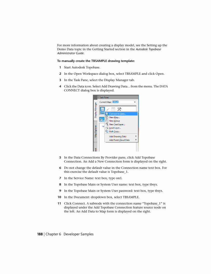
For more information about creating a display model, see the Setting up theDemo Data topic in the Getting Started section in the Autodesk TopobaseAdministrator Guide.
To manually create the TBSAMPLE drawing template:
1 Start Autodesk Topobase.
2 In the Open Workspace dialog box, select TBSAMPLE and click Open.
3 In the Task Pane, select the Display Manager tab.
4 Click the Data icon. Select Add Drawing Data... from the menu. The DATACONNECT dialog box is displayed.
5 In the Data Connections By Provider pane, click Add TopobaseConnection. An Add a New Connection form is displayed on the right.
6 Do not change the default value in the Connection name text box. Forthis exercise the default value is Topobase_1.
7 In the Service Name: text box, type orcl.
8 In the Topobase Main or System User name: text box, type tbsys.
9 In the Topobase Main or System User password: text box, type tbsys.
10 In the Document: dropdown box, select TBSAMPLE.
11 Click Connect. A subnode with the connection name “Topobase_1” isdisplayed under the Add Topobase Connection feature source node onthe left. An Add Data to Map form is displayed on the right.
188 | Chapter 6 Developer Samples
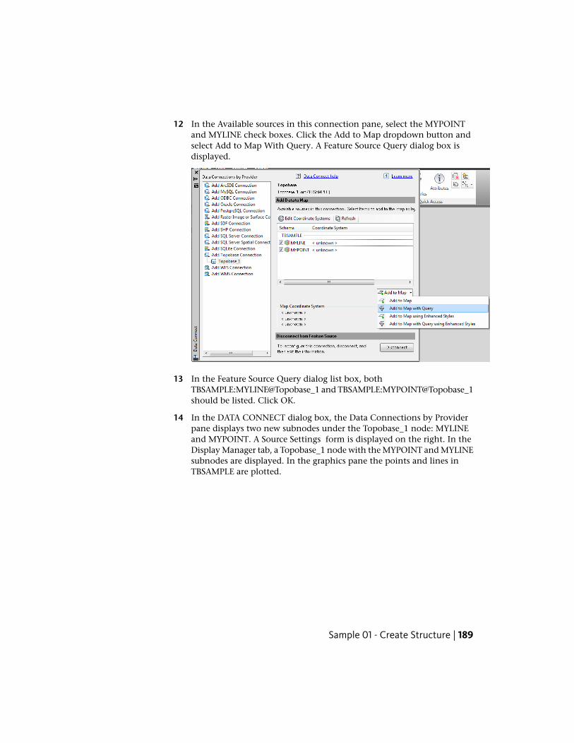
12 In the Available sources in this connection pane, select the MYPOINTand MYLINE check boxes. Click the Add to Map dropdown button andselect Add to Map With Query. A Feature Source Query dialog box isdisplayed.
13 In the Feature Source Query dialog list box, bothTBSAMPLE:MYLINE@Topobase_1 and TBSAMPLE:MYPOINT@Topobase_1should be listed. Click OK.
14 In the DATA CONNECT dialog box, the Data Connections by Providerpane displays two new subnodes under the Topobase_1 node: MYLINEand MYPOINT. A Source Settings form is displayed on the right. In theDisplay Manager tab, a Topobase_1 node with the MYPOINT and MYLINEsubnodes are displayed. In the graphics pane the points and lines inTBSAMPLE are plotted.
Sample 01 - Create Structure | 189
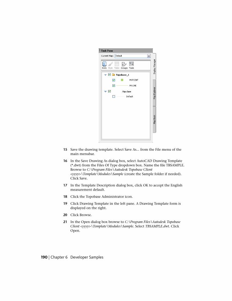
15 Save the drawing template. Select Save As... from the File menu of themain menubar.
16 In the Save Drawing As dialog box, select AutoCAD Drawing Template(*.dwt) from the Files Of Type dropdown box. Name the file TBSAMPLE.Browse to C:\Program Files\Autodesk Topobase Client<yyyy>\Template\Modules\Sample (create the Sample folder if needed).Click Save.
17 In the Template Description dialog box, click OK to accept the Englishmeasurement default.
18 Click the Topobase Administrator icon.
19 Click Drawing Template in the left pane. A Drawing Template form isdisplayed on the right.
20 Click Browse.
21 In the Open dialog box browse to C:\Program Files\Autodesk TopobaseClient <yyyy>\Template\Modules\Sample. Select TBSAMPLE.dwt. ClickOpen.
190 | Chapter 6 Developer Samples
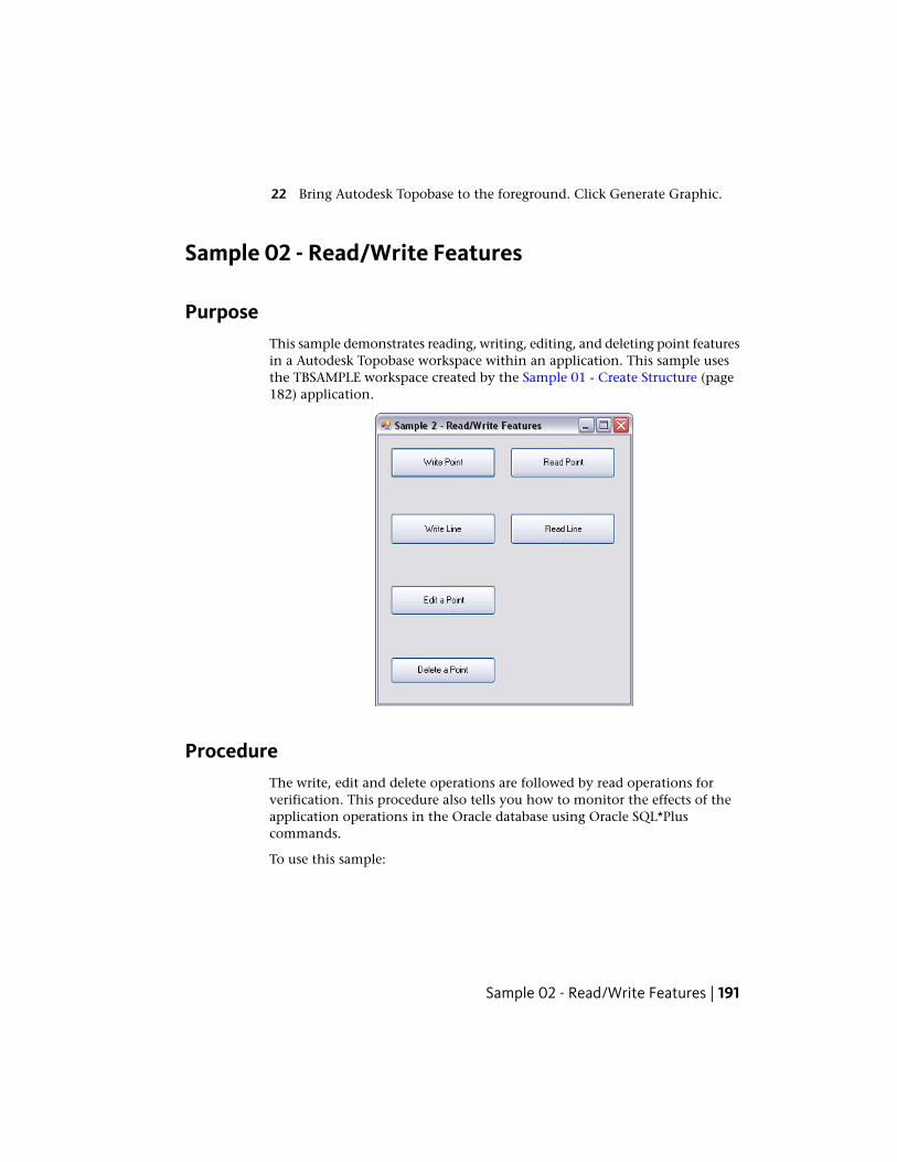
22 Bring Autodesk Topobase to the foreground. Click Generate Graphic.
Sample 02 - Read/Write Features
PurposeThis sample demonstrates reading, writing, editing, and deleting point featuresin a Autodesk Topobase workspace within an application. This sample usesthe TBSAMPLE workspace created by the Sample 01 - Create Structure (page182) application.
ProcedureThe write, edit and delete operations are followed by read operations forverification. This procedure also tells you how to monitor the effects of theapplication operations in the Oracle database using Oracle SQL*Pluscommands.
To use this sample:
Sample 02 - Read/Write Features | 191
1 Build the sample. The plugin (VBSample02.dll or CSSample02.dll) and theassociated .tbp file are copied to the Autodesk Topobase Client bindirectory.
2 Start Autodesk Topobase and open the TBSAMPLE workspace.
3 Click the application toolbar button with the Sample 02 - Read WriteFeatures tooltip. The sample’s dialog box is displayed.
4 Click the Write Point button.
NOTE A form with a progress bar is displayed. This indicates that aconnection is being made to the Autodesk Topobase workspace. At the endof the write operation the connection is closed. Each time you click a buttonon this form a connection to a workspace is opened and closed. Thedescriptions of the other operations do not repeat this information.
5 In the XY Input dialog box, type a number in the X text box and in theY text box and click OK. The result is that an untitled message box isdisplayed telling the feature ID number of the point that you just added.Click OK.
To display the results of this operation in the TBSAMPLE user tables inyour Oracle instance, enter the following commands at a commandprompt:
sqlplus /nolog
connect tbsample/avs
select fid,geom from mypoint;
6 Click the Read Point button. Type the feature ID number returned by thewrite point operation into the FID text box in the Feature Class ID dialogbox. Click OK. A message box is displayed showing the X and Y valuesthat you specified during the write point operation. Click OK.
7 Click the Edit a Point button. Type the feature ID number returned bythe write point operation into the FID text box in the Feature Class IDdialog box. Click OK. In the XY Input dialog box type a number in theX text box and in the Y text box and click OK. Use Read Point from theprevious step again to verify that you have changed the values of thisfeature.
8 Click the Delete a Point button. Click the OK button in theTBConnectionState: Successful message box. Type the feature ID numberreturned by the write point operation into the FID text box in the FeatureClass ID dialog box. Click OK. Click the OK button in the Deletion ofMYPOINT Feature With FID = <number> Succeeded message box.
192 | Chapter 6 Developer Samples
9 Click the Read Point button. Type the feature ID number returned by thewrite point operation into the FID text box in the Feature Class ID dialogbox. Click OK. Click the OK button in the Feature With This FID NotFound message box.
At any time during the execution of this sample, right-click MyPoint andselect Show Form to display the points and lines created by this sample.
Sample 03 - Oracle Data Provider (ODP) .Net
PurposeThis sample shows how to access data using the Oracle Data Provider (ODP)and Microsoft’s .Net technology. The code features the use of the followingclasses:
■ Topobase.Data.TBConnection
■ Topobase.Data.Provider.Command
■ Topobase.Data.Provider.DataReader
■ Topobase.Data.Provider.DataAdapter
■ Topobase.Data.DBTable
■ Topobase.Data.Row
■ Topobase.Data.Attribute
ProcedureTo use this sample:
1 Build the sample. The plugin (VBSample03.dll or CSSample03.dll) and theassociated .tbp file are copied to the Autodesk Topobase Client bindirectory.
2 Start Autodesk Topobase and open the TBSAMPLE workspace.
3 Click Setup ➤ Sample 03 - ODP. The samples dialog box is displayed.
Sample 03 - Oracle Data Provider (ODP) .Net | 193
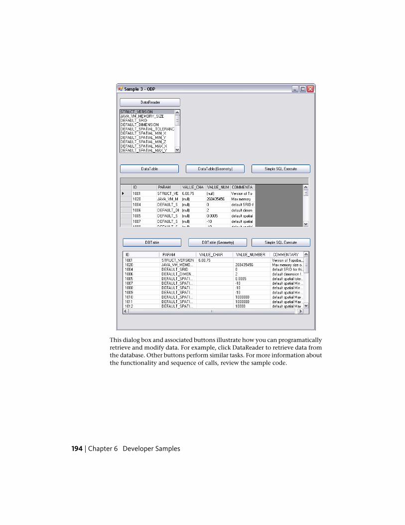
This dialog box and associated buttons illustrate how you can programaticallyretrieve and modify data. For example, click DataReader to retrieve data fromthe database. Other buttons perform similar tasks. For more information aboutthe functionality and sequence of calls, review the sample code.
194 | Chapter 6 Developer Samples
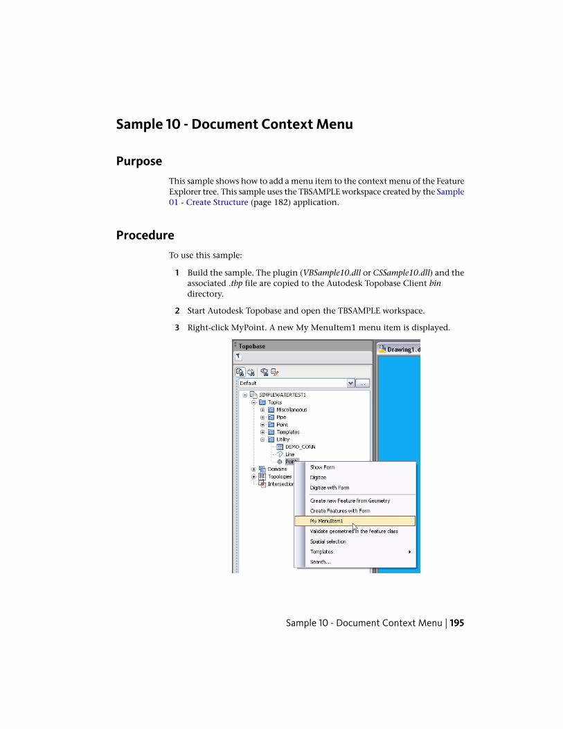
Sample 10 - Document Context Menu
PurposeThis sample shows how to add a menu item to the context menu of the FeatureExplorer tree. This sample uses the TBSAMPLE workspace created by the Sample01 - Create Structure (page 182) application.
ProcedureTo use this sample:
1 Build the sample. The plugin (VBSample10.dll or CSSample10.dll) and theassociated .tbp file are copied to the Autodesk Topobase Client bindirectory.
2 Start Autodesk Topobase and open the TBSAMPLE workspace.
3 Right-click MyPoint. A new My MenuItem1 menu item is displayed.
Sample 10 - Document Context Menu | 195
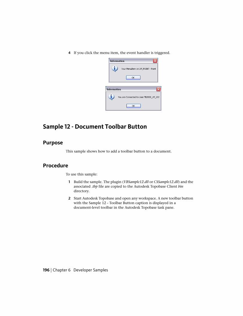
4 If you click the menu item, the event handler is triggered.
Sample 12 - Document Toolbar Button
PurposeThis sample shows how to add a toolbar button to a document.
ProcedureTo use this sample:
1 Build the sample. The plugin (VBSample12.dll or CSSample12.dll) and theassociated .tbp file are copied to the Autodesk Topobase Client bindirectory.
2 Start Autodesk Topobase and open any workspace. A new toolbar buttonwith the Sample 12 - Toolbar Button caption is displayed in adocument-level toolbar in the Autodesk Topobase task pane.
196 | Chapter 6 Developer Samples
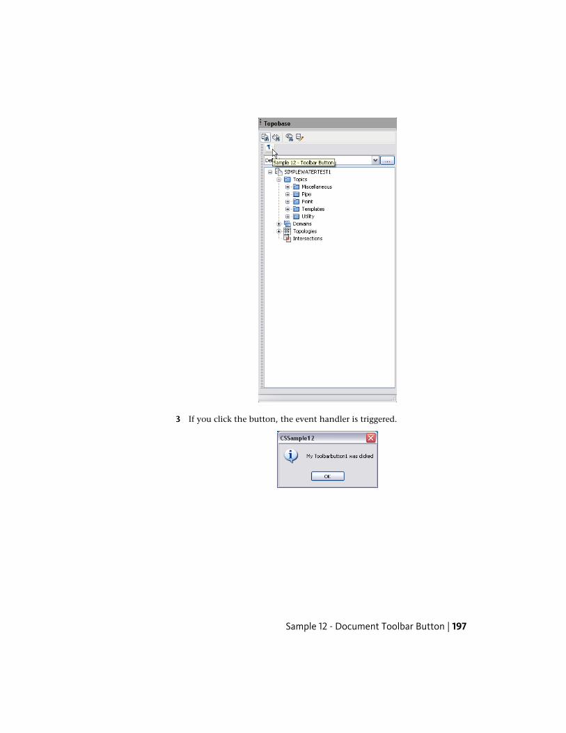
3 If you click the button, the event handler is triggered.
Sample 12 - Document Toolbar Button | 197
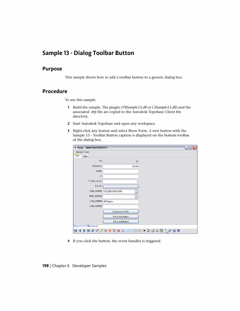
Sample 13 - Dialog Toolbar Button
PurposeThis sample shows how to add a toolbar button to a generic dialog box.
ProcedureTo use this sample:
1 Build the sample. The plugin (VBSample13.dll or CSSample13.dll) and theassociated .tbp file are copied to the Autodesk Topobase Client bindirectory.
2 Start Autodesk Topobase and open any workspace.
3 Right-click any feature and select Show Form. A new button with theSample 13 - Toolbar Button caption is displayed on the bottom toolbarof the dialog box.
4 If you click the button, the event handler is triggered.
198 | Chapter 6 Developer Samples
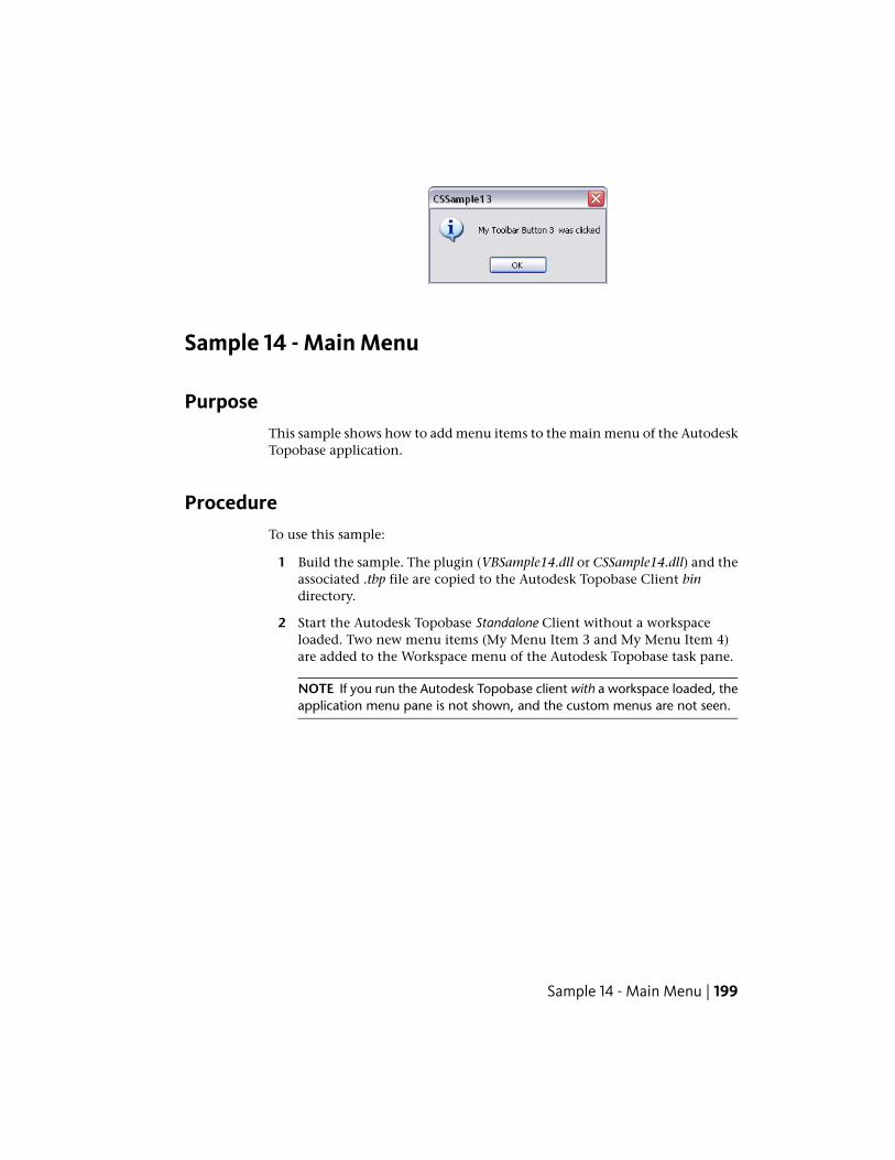
Sample 14 - Main Menu
PurposeThis sample shows how to add menu items to the main menu of the AutodeskTopobase application.
ProcedureTo use this sample:
1 Build the sample. The plugin (VBSample14.dll or CSSample14.dll) and theassociated .tbp file are copied to the Autodesk Topobase Client bindirectory.
2 Start the Autodesk Topobase Standalone Client without a workspaceloaded. Two new menu items (My Menu Item 3 and My Menu Item 4)are added to the Workspace menu of the Autodesk Topobase task pane.
NOTE If you run the Autodesk Topobase client with a workspace loaded, theapplication menu pane is not shown, and the custom menus are not seen.
Sample 14 - Main Menu | 199
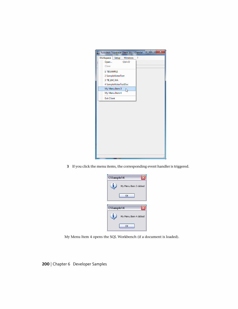
3 If you click the menu items, the corresponding event handler is triggered.
My Menu Item 4 opens the SQL Workbench (if a document is loaded).
200 | Chapter 6 Developer Samples
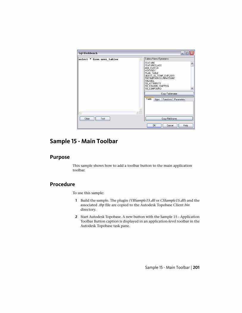
Sample 15 - Main Toolbar
PurposeThis sample shows how to add a toolbar button to the main applicationtoolbar.
ProcedureTo use this sample:
1 Build the sample. The plugin (VBSample15.dll or CSSample15.dll) and theassociated .tbp file are copied to the Autodesk Topobase Client bindirectory.
2 Start Autodesk Topobase. A new button with the Sample 15 - ApplicationToolbar Button caption is displayed in an application-level toolbar in theAutodesk Topobase task pane.
Sample 15 - Main Toolbar | 201
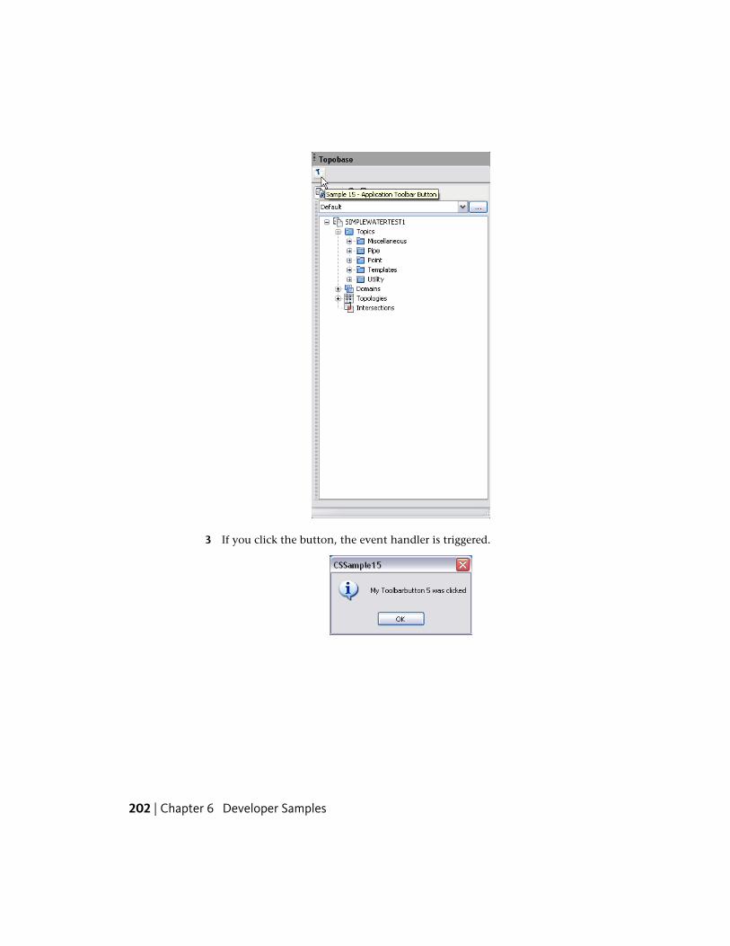
3 If you click the button, the event handler is triggered.
202 | Chapter 6 Developer Samples
Sample 16 - Dialog Button
PurposeThis sample shows how to add a toolbar button to a generic dialog box. Thissample uses the TBSAMPLE workspace created by the Sample 01 - CreateStructure (page 182) application.
ProcedureTo use this sample:
1 If you have not already done so, run Sample 01 to create the TBSAMPLEworkspace. (See Sample 01 - Create Structure (page 182).)
2 Add a control to the generic dialog box for MyPoint.
NOTE You must do this first before building the sample. If you do not, anerror message “Control $myButton1 not found in Dialog” is displayed.
1 Start Autodesk Topobase Administrator and open the TBSAMPLEworkspace.
Sample 16 - Dialog Button | 203
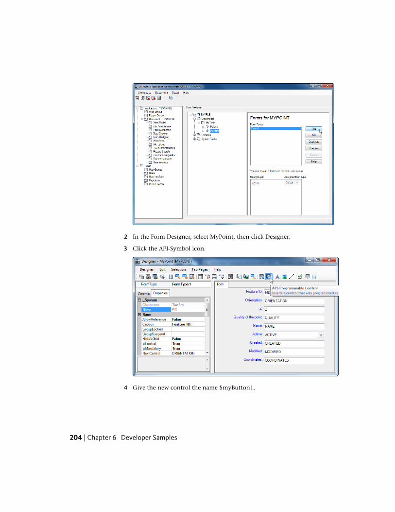
2 In the Form Designer, select MyPoint, then click Designer.
3 Click the API-Symbol icon.
4 Give the new control the name $myButton1.
204 | Chapter 6 Developer Samples
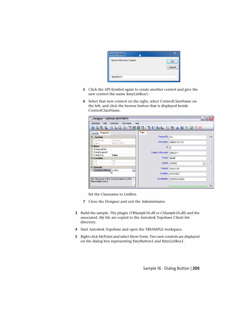
5 Click the API-Symbol again to create another control and give thenew control the name $myListBox1.
6 Select that new control on the right, select ControlClassName onthe left, and click the browse button that is displayed besideControlClassName.
Set the Classname to ListBox.
7 Close the Designer and exit the Administrator.
3 Build the sample. The plugin (VBSample16.dll or CSSample16.dll) and theassociated .tbp file are copied to the Autodesk Topobase Client bindirectory.
4 Start Autodesk Topobase and open the TBSAMPLE workspace.
5 Right-click MyPoint and select Show Form. Two new controls are displayedon the dialog box representing $myButton1 and $myListBox1.
Sample 16 - Dialog Button | 205
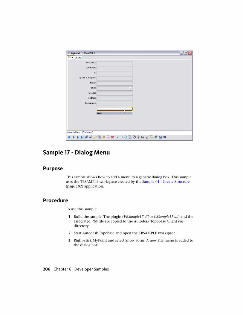
Sample 17 - Dialog Menu
PurposeThis sample shows how to add a menu to a generic dialog box. This sampleuses the TBSAMPLE workspace created by the Sample 01 - Create Structure(page 182) application.
ProcedureTo use this sample:
1 Build the sample. The plugin (VBSample17.dll or CSSample17.dll) and theassociated .tbp file are copied to the Autodesk Topobase Client bindirectory.
2 Start Autodesk Topobase and open the TBSAMPLE workspace.
3 Right-click MyPoint and select Show Form. A new File menu is added tothe dialog box.
206 | Chapter 6 Developer Samples
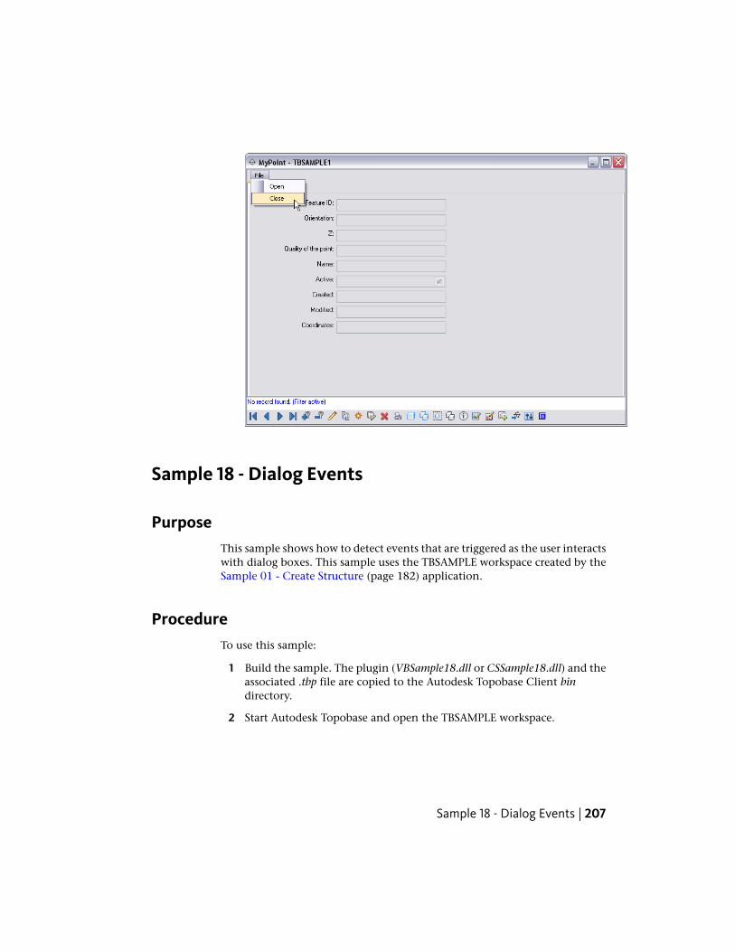
Sample 18 - Dialog Events
PurposeThis sample shows how to detect events that are triggered as the user interactswith dialog boxes. This sample uses the TBSAMPLE workspace created by theSample 01 - Create Structure (page 182) application.
ProcedureTo use this sample:
1 Build the sample. The plugin (VBSample18.dll or CSSample18.dll) and theassociated .tbp file are copied to the Autodesk Topobase Client bindirectory.
2 Start Autodesk Topobase and open the TBSAMPLE workspace.
Sample 18 - Dialog Events | 207
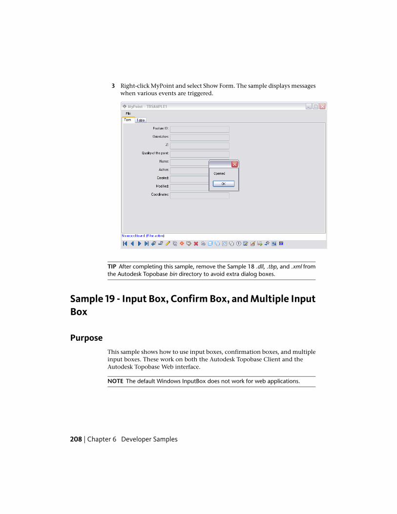
3 Right-click MyPoint and select Show Form. The sample displays messageswhen various events are triggered.
TIP After completing this sample, remove the Sample 18 .dll, .tbp, and .xml fromthe Autodesk Topobase bin directory to avoid extra dialog boxes.
Sample 19 - Input Box, Confirm Box, and Multiple InputBox
PurposeThis sample shows how to use input boxes, confirmation boxes, and multipleinput boxes. These work on both the Autodesk Topobase Client and theAutodesk Topobase Web interface.
NOTE The default Windows InputBox does not work for web applications.
208 | Chapter 6 Developer Samples
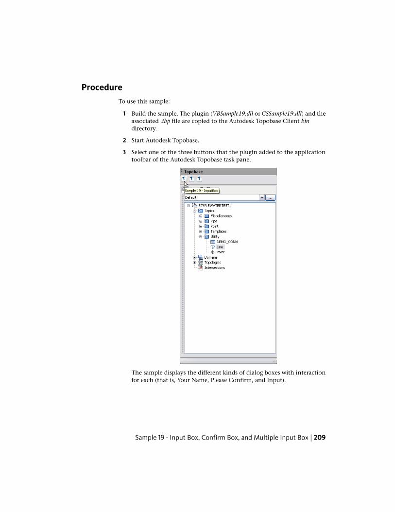
ProcedureTo use this sample:
1 Build the sample. The plugin (VBSample19.dll or CSSample19.dll) and theassociated .tbp file are copied to the Autodesk Topobase Client bindirectory.
2 Start Autodesk Topobase.
3 Select one of the three buttons that the plugin added to the applicationtoolbar of the Autodesk Topobase task pane.
The sample displays the different kinds of dialog boxes with interactionfor each (that is, Your Name, Please Confirm, and Input).
Sample 19 - Input Box, Confirm Box, and Multiple Input Box | 209
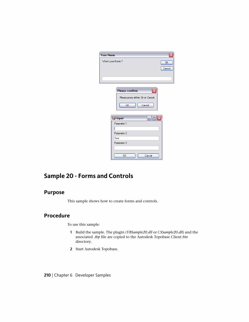
Sample 20 - Forms and Controls
PurposeThis sample shows how to create forms and controls.
ProcedureTo use this sample:
1 Build the sample. The plugin (VBSample20.dll or CSSample20.dll) and theassociated .tbp file are copied to the Autodesk Topobase Client bindirectory.
2 Start Autodesk Topobase.
210 | Chapter 6 Developer Samples
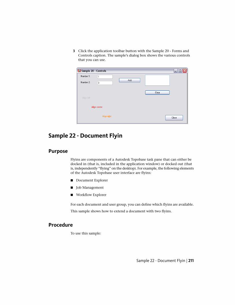
3 Click the application toolbar button with the Sample 20 - Forms andControls caption. The sample’s dialog box shows the various controlsthat you can use.
Sample 22 - Document Flyin
PurposeFlyins are components of a Autodesk Topobase task pane that can either bedocked in (that is, included in the application window) or docked out (thatis, independently “flying” on the desktop). For example, the following elementsof the Autodesk Topobase user interface are flyins:
■ Document Explorer
■ Job Management
■ Workflow Explorer
For each document and user group, you can define which flyins are available.
This sample shows how to extend a document with two flyins.
ProcedureTo use this sample:
Sample 22 - Document Flyin | 211
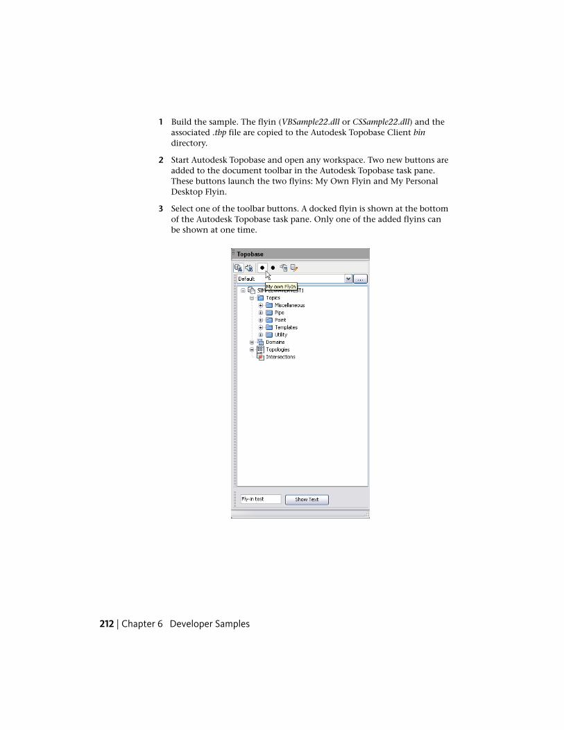
1 Build the sample. The flyin (VBSample22.dll or CSSample22.dll) and theassociated .tbp file are copied to the Autodesk Topobase Client bindirectory.
2 Start Autodesk Topobase and open any workspace. Two new buttons areadded to the document toolbar in the Autodesk Topobase task pane.These buttons launch the two flyins: My Own Flyin and My PersonalDesktop Flyin.
3 Select one of the toolbar buttons. A docked flyin is shown at the bottomof the Autodesk Topobase task pane. Only one of the added flyins canbe shown at one time.
212 | Chapter 6 Developer Samples
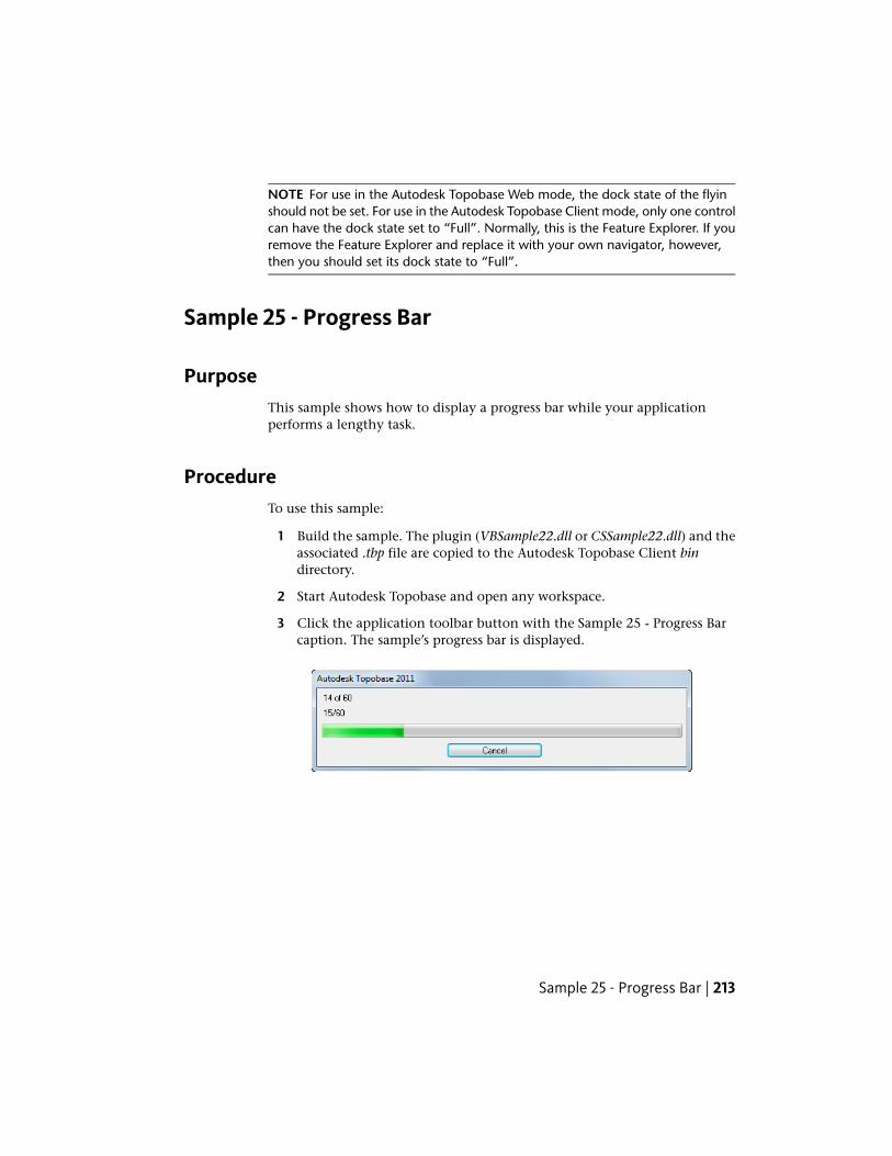
NOTE For use in the Autodesk Topobase Web mode, the dock state of the flyinshould not be set. For use in the Autodesk Topobase Client mode, only one controlcan have the dock state set to “Full”. Normally, this is the Feature Explorer. If youremove the Feature Explorer and replace it with your own navigator, however,then you should set its dock state to “Full”.
Sample 25 - Progress Bar
PurposeThis sample shows how to display a progress bar while your applicationperforms a lengthy task.
ProcedureTo use this sample:
1 Build the sample. The plugin (VBSample22.dll or CSSample22.dll) and theassociated .tbp file are copied to the Autodesk Topobase Client bindirectory.
2 Start Autodesk Topobase and open any workspace.
3 Click the application toolbar button with the Sample 25 - Progress Barcaption. The sample’s progress bar is displayed.
Sample 25 - Progress Bar | 213
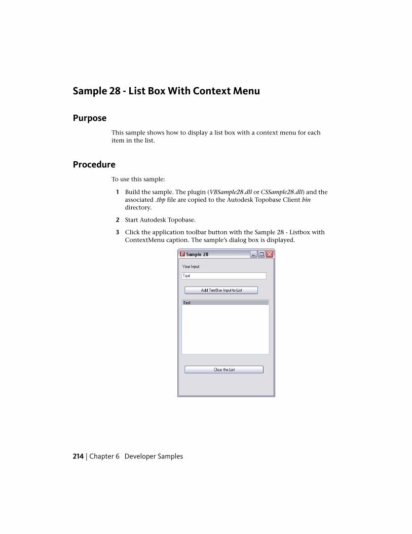
Sample 28 - List Box With Context Menu
PurposeThis sample shows how to display a list box with a context menu for eachitem in the list.
ProcedureTo use this sample:
1 Build the sample. The plugin (VBSample28.dll or CSSample28.dll) and theassociated .tbp file are copied to the Autodesk Topobase Client bindirectory.
2 Start Autodesk Topobase.
3 Click the application toolbar button with the Sample 28 - Listbox withContextMenu caption. The sample’s dialog box is displayed.
214 | Chapter 6 Developer Samples
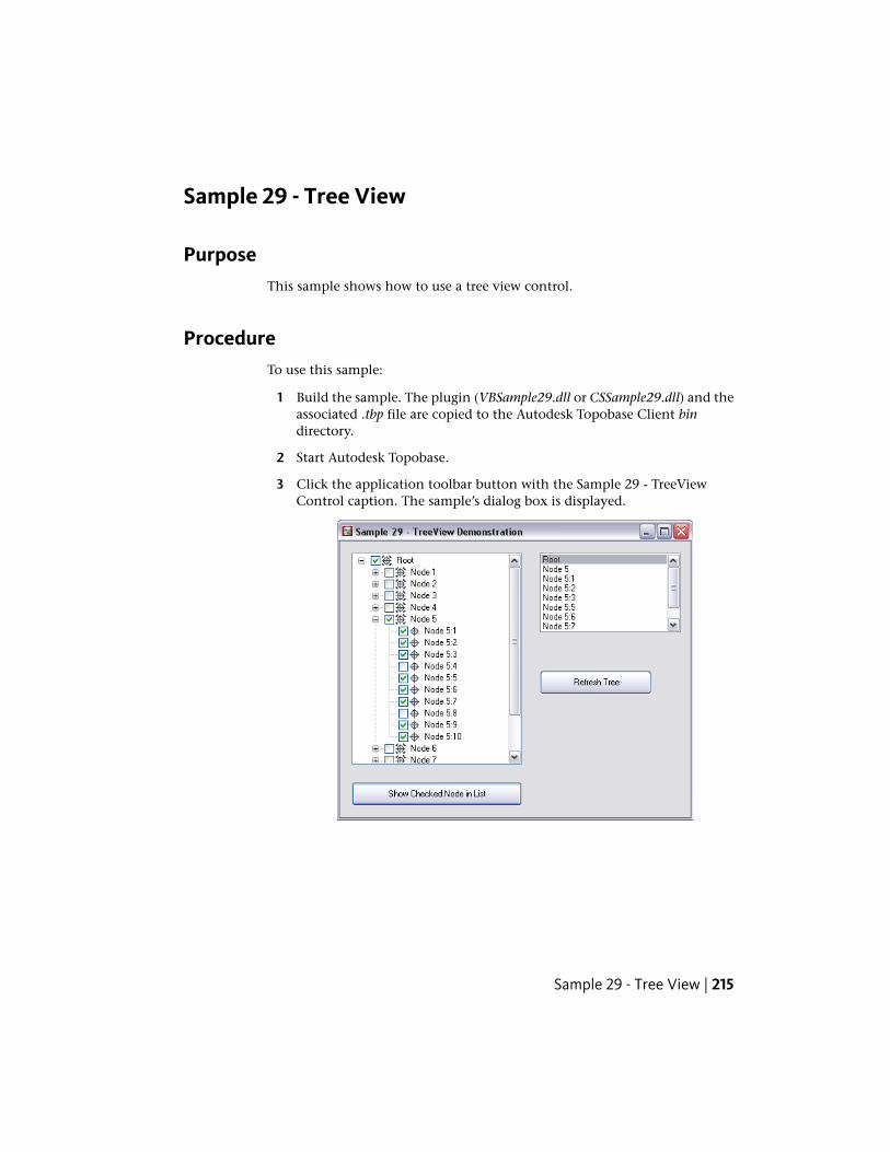
Sample 29 - Tree View
PurposeThis sample shows how to use a tree view control.
ProcedureTo use this sample:
1 Build the sample. The plugin (VBSample29.dll or CSSample29.dll) and theassociated .tbp file are copied to the Autodesk Topobase Client bindirectory.
2 Start Autodesk Topobase.
3 Click the application toolbar button with the Sample 29 - TreeViewControl caption. The sample’s dialog box is displayed.
Sample 29 - Tree View | 215
Sample 30 - Map Button
PurposeThis sample shows how to retrieve the coordinates defining features for threefeature types: point, polygon, and rectangle.
ProcedureTo use this sample:
1 Build the sample. The plugin (VBSample30.dll or CSSample30.dll) and theassociated .tbp file are copied to the Autodesk Topobase Client bindirectory.
2 Start Autodesk Topobase and open the land management demonstrationworkspace (for example, TB2009_LM_102) whose creation is describedin the Autodesk Topobase Installation and Configuration Guide.
3 Click Generate Graphic.
4 Click the document toolbar button with the Sample 30 - MapButtonControl caption.
The sample’s dialog box is displayed.
216 | Chapter 6 Developer Samples
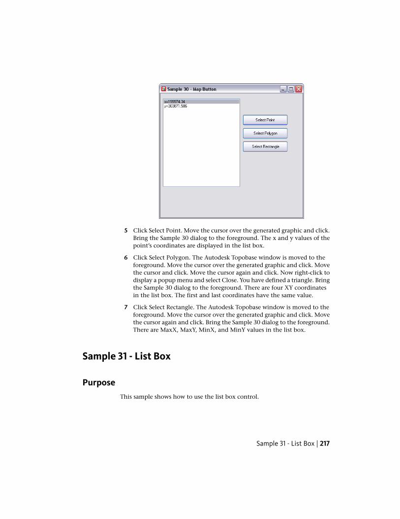
5 Click Select Point. Move the cursor over the generated graphic and click.Bring the Sample 30 dialog to the foreground. The x and y values of thepoint’s coordinates are displayed in the list box.
6 Click Select Polygon. The Autodesk Topobase window is moved to theforeground. Move the cursor over the generated graphic and click. Movethe cursor and click. Move the cursor again and click. Now right-click todisplay a popup menu and select Close. You have defined a triangle. Bringthe Sample 30 dialog to the foreground. There are four XY coordinatesin the list box. The first and last coordinates have the same value.
7 Click Select Rectangle. The Autodesk Topobase window is moved to theforeground. Move the cursor over the generated graphic and click. Movethe cursor again and click. Bring the Sample 30 dialog to the foreground.There are MaxX, MaxY, MinX, and MinY values in the list box.
Sample 31 - List Box
PurposeThis sample shows how to use the list box control.
Sample 31 - List Box | 217
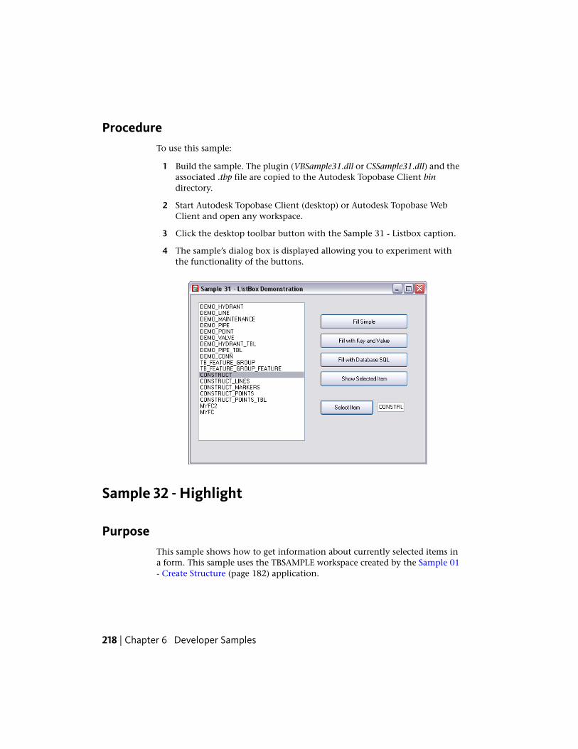
ProcedureTo use this sample:
1 Build the sample. The plugin (VBSample31.dll or CSSample31.dll) and theassociated .tbp file are copied to the Autodesk Topobase Client bindirectory.
2 Start Autodesk Topobase Client (desktop) or Autodesk Topobase WebClient and open any workspace.
3 Click the desktop toolbar button with the Sample 31 - Listbox caption.
4 The sample’s dialog box is displayed allowing you to experiment withthe functionality of the buttons.
Sample 32 - Highlight
PurposeThis sample shows how to get information about currently selected items ina form. This sample uses the TBSAMPLE workspace created by the Sample 01- Create Structure (page 182) application.
218 | Chapter 6 Developer Samples
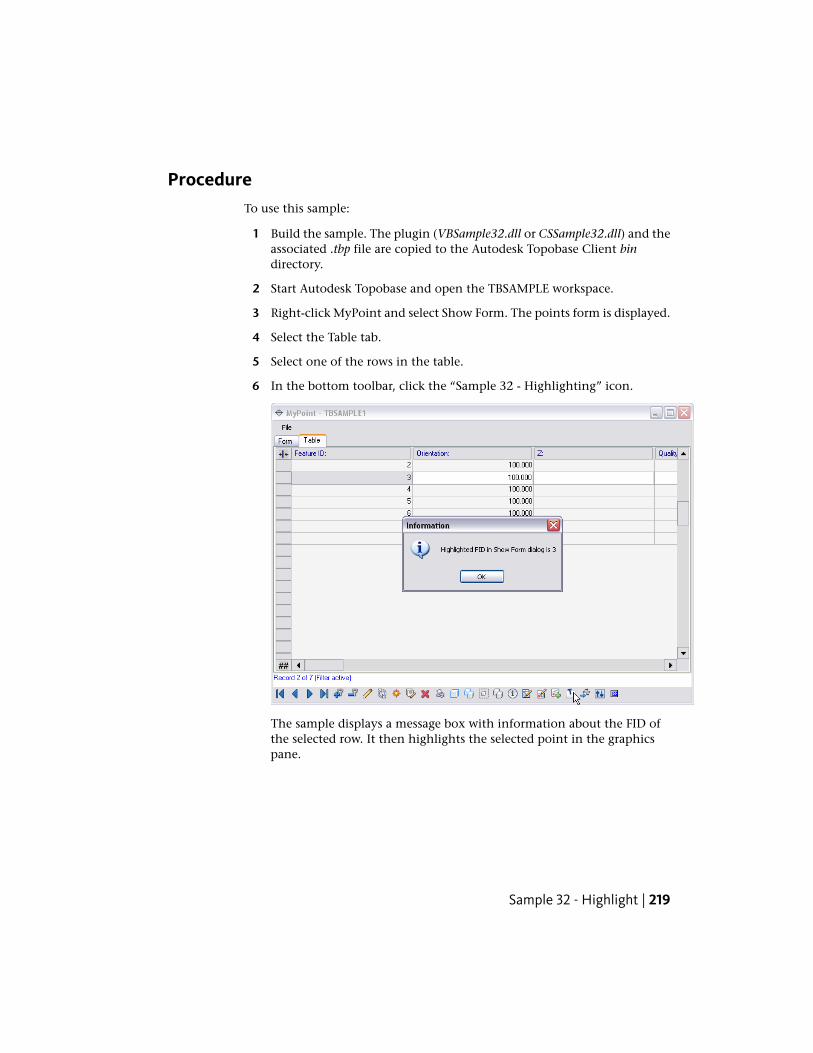
ProcedureTo use this sample:
1 Build the sample. The plugin (VBSample32.dll or CSSample32.dll) and theassociated .tbp file are copied to the Autodesk Topobase Client bindirectory.
2 Start Autodesk Topobase and open the TBSAMPLE workspace.
3 Right-click MyPoint and select Show Form. The points form is displayed.
4 Select the Table tab.
5 Select one of the rows in the table.
6 In the bottom toolbar, click the “Sample 32 - Highlighting” icon.
The sample displays a message box with information about the FID ofthe selected row. It then highlights the selected point in the graphicspane.
Sample 32 - Highlight | 219
Sample 33 - Information
PurposeThis sample shows how to use the Feature Information icon to display theShow Form dialog box with a selected feature displayed in the dialog box.This sample uses the TBSAMPLE workspace created by the Sample 01 - CreateStructure (page 182) application.
ProcedureTo use this sample:
1 Build the sample. The plugin (VBSample33.dll or CSSample33.dll) and theassociated .tbp file are copied to the Autodesk Topobase Client bindirectory.
2 Start Autodesk Topobase and open the TBSAMPLE workspace.
NOTE If you have not already done so, use Sample 02 to add a couple ofpoints and a line to the TBSAMPLE workspace. Or, add them manually byright-clicking MyPoint and MyLine, choosing Show Form, and adding records.
3 Click Generate Graphic.
TIP If needed, you can right-click on a feature in the Display Manager paneand select Zoom to Extents to more easily view the object.
4 In the graphics pane, click a point.
5 Click the Attributes item in the ribbon or in the context menu of thepoint. The message box is displayed with the Sample 33 OnInfo handlerrunning: e.DialogName: MYPOINT text. Click OK. A show form MyPoint- TBSAMPLE dialog box is displayed with the Form tab selected. This tabcontains information about the selected point.
6 In the graphics pane, click a line.
7 Click the feature information button. A message box is displayed withthe Sample 33 OnInfo handler running: e.DialogName: MYLINE text.Click OK. A show form MyLine - TBSAMPLE dialog box is displayed with
220 | Chapter 6 Developer Samples
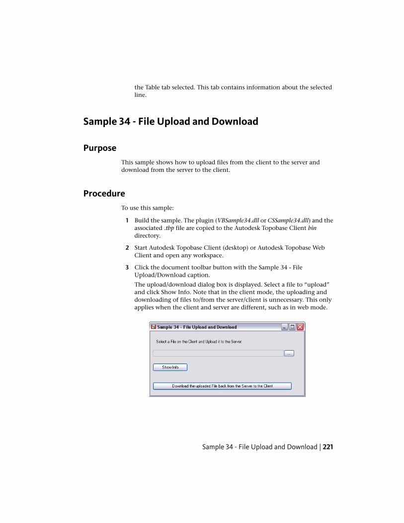
the Table tab selected. This tab contains information about the selectedline.
Sample 34 - File Upload and Download
PurposeThis sample shows how to upload files from the client to the server anddownload from the server to the client.
ProcedureTo use this sample:
1 Build the sample. The plugin (VBSample34.dll or CSSample34.dll) and theassociated .tbp file are copied to the Autodesk Topobase Client bindirectory.
2 Start Autodesk Topobase Client (desktop) or Autodesk Topobase WebClient and open any workspace.
3 Click the document toolbar button with the Sample 34 - FileUpload/Download caption.
The upload/download dialog box is displayed. Select a file to “upload”and click Show Info. Note that in the client mode, the uploading anddownloading of files to/from the server/client is unnecessary. This onlyapplies when the client and server are different, such as in web mode.
Sample 34 - File Upload and Download | 221
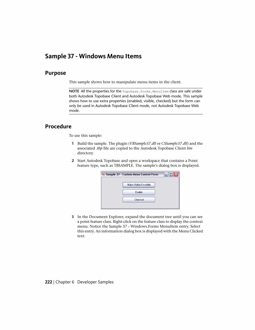
Sample 37 - Windows Menu Items
PurposeThis sample shows how to manipulate menu items in the client.
NOTE All the properties for the Topobase.Forms.MenuItem class are safe underboth Autodesk Topobase Client and Autodesk Topobase Web mode. This sampleshows how to use extra properties (enabled, visible, checked) but the form canonly be used in Autodesk Topobase Client mode, not Autodesk Topobase Webmode.
ProcedureTo use this sample:
1 Build the sample. The plugin (VBSample37.dll or CSSample37.dll) and theassociated .tbp file are copied to the Autodesk Topobase Client bindirectory.
2 Start Autodesk Topobase and open a workspace that contains a Pointfeature type, such as TBSAMPLE. The sample’s dialog box is displayed.
3 In the Document Explorer, expand the document tree until you can seea point feature class. Right-click on the feature class to display the contextmenu. Notice the Sample 37 - Windows.Forms MenuItem entry. Selectthis entry. An information dialog box is displayed with the Menu Clickedtext.
222 | Chapter 6 Developer Samples
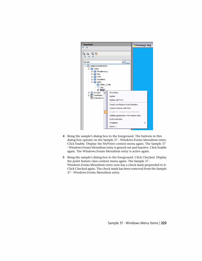
4 Bring the sample’s dialog box to the foreground. The buttons in thisdialog box operate on the Sample 37 - Windows.Forms MenuItem entry.Click Enable. Display the MyPoint context menu again. The Sample 37- Windows.Forms MenuItem entry is greyed out and inactive. Click Enableagain. The Windows.Forms MenuItem entry is active again.
5 Bring the sample’s dialog box to the foreground. Click Checked. Displaythe point feature class context menu again. The Sample 37 -Windows.Forms MenuItem entry now has a check mark prepended to it.Click Checked again. The check mark has been removed from the Sample37 - Windows.Forms MenuItem entry.
Sample 37 - Windows Menu Items | 223
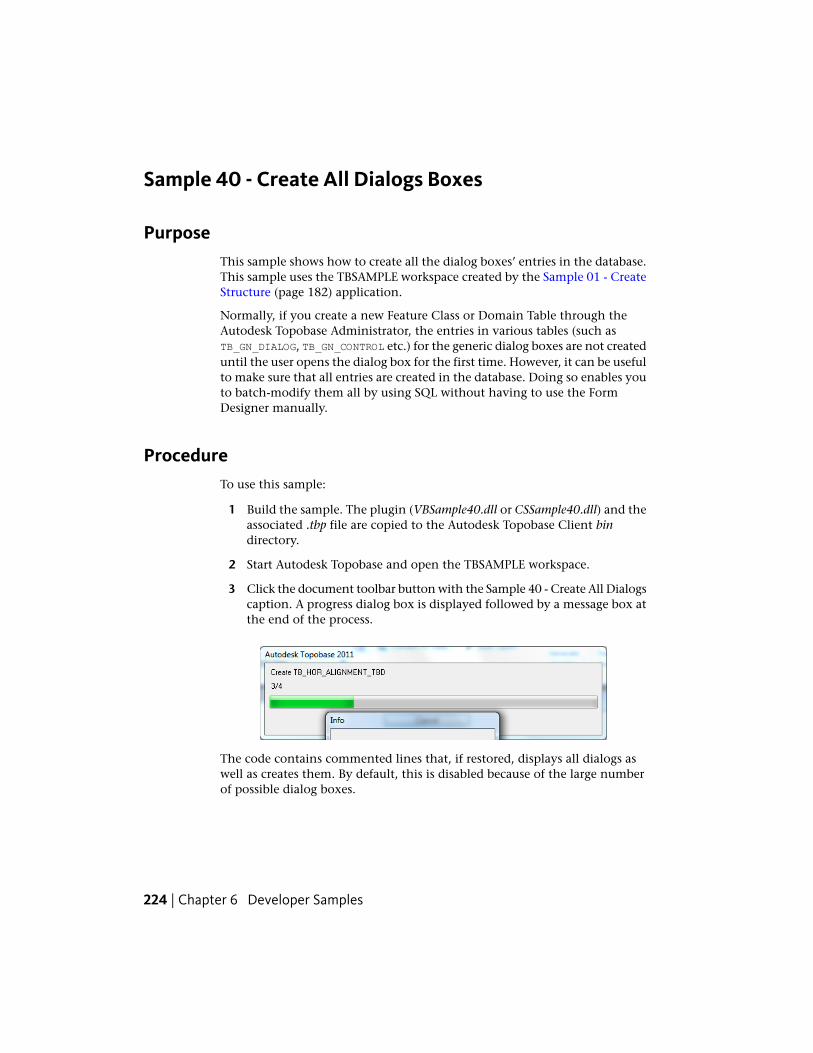
Sample 40 - Create All Dialogs Boxes
PurposeThis sample shows how to create all the dialog boxes’ entries in the database.This sample uses the TBSAMPLE workspace created by the Sample 01 - CreateStructure (page 182) application.
Normally, if you create a new Feature Class or Domain Table through theAutodesk Topobase Administrator, the entries in various tables (such asTB_GN_DIALOG, TB_GN_CONTROL etc.) for the generic dialog boxes are not createduntil the user opens the dialog box for the first time. However, it can be usefulto make sure that all entries are created in the database. Doing so enables youto batch-modify them all by using SQL without having to use the FormDesigner manually.
ProcedureTo use this sample:
1 Build the sample. The plugin (VBSample40.dll or CSSample40.dll) and theassociated .tbp file are copied to the Autodesk Topobase Client bindirectory.
2 Start Autodesk Topobase and open the TBSAMPLE workspace.
3 Click the document toolbar button with the Sample 40 - Create All Dialogscaption. A progress dialog box is displayed followed by a message box atthe end of the process.
The code contains commented lines that, if restored, displays all dialogs aswell as creates them. By default, this is disabled because of the large numberof possible dialog boxes.
224 | Chapter 6 Developer Samples
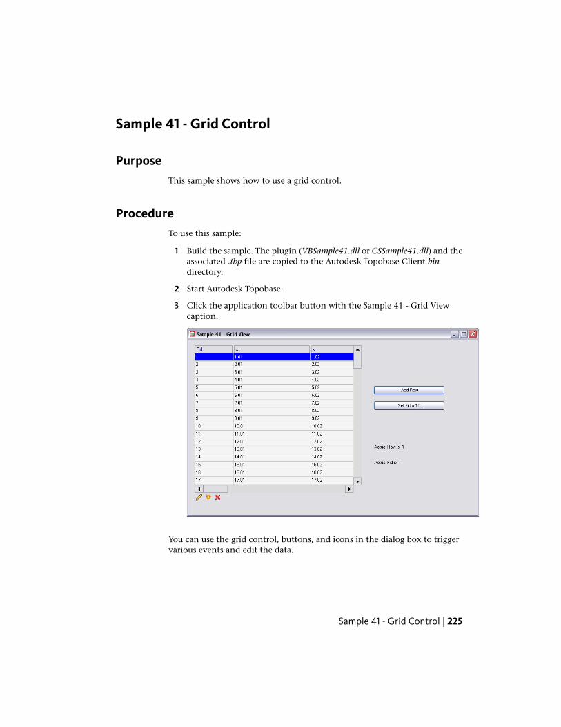
Sample 41 - Grid Control
PurposeThis sample shows how to use a grid control.
ProcedureTo use this sample:
1 Build the sample. The plugin (VBSample41.dll or CSSample41.dll) and theassociated .tbp file are copied to the Autodesk Topobase Client bindirectory.
2 Start Autodesk Topobase.
3 Click the application toolbar button with the Sample 41 - Grid Viewcaption.
You can use the grid control, buttons, and icons in the dialog box to triggervarious events and edit the data.
Sample 41 - Grid Control | 225
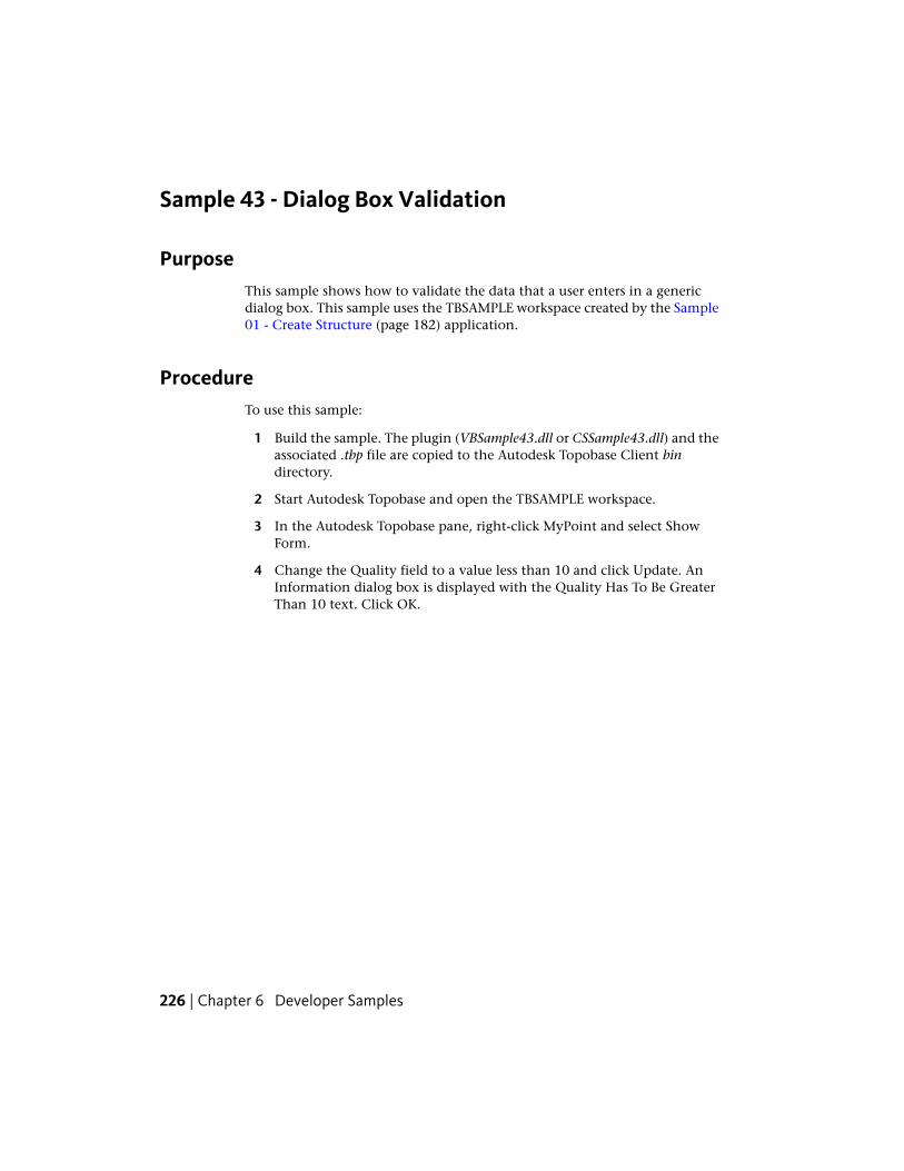
Sample 43 - Dialog Box Validation
PurposeThis sample shows how to validate the data that a user enters in a genericdialog box. This sample uses the TBSAMPLE workspace created by the Sample01 - Create Structure (page 182) application.
ProcedureTo use this sample:
1 Build the sample. The plugin (VBSample43.dll or CSSample43.dll) and theassociated .tbp file are copied to the Autodesk Topobase Client bindirectory.
2 Start Autodesk Topobase and open the TBSAMPLE workspace.
3 In the Autodesk Topobase pane, right-click MyPoint and select ShowForm.
4 Change the Quality field to a value less than 10 and click Update. AnInformation dialog box is displayed with the Quality Has To Be GreaterThan 10 text. Click OK.
226 | Chapter 6 Developer Samples
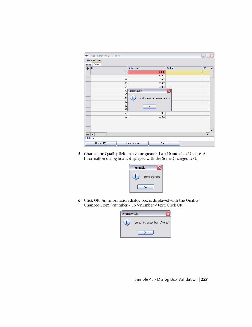
5 Change the Quality field to a value greater than 10 and click Update. AnInformation dialog box is displayed with the Some Changed text.
6 Click OK. An Information dialog box is displayed with the QualityChanged From ‘<number>’ To ‘<number>’ text. Click OK.
Sample 43 - Dialog Box Validation | 227
Sample 44 - Menus and Toolbars
PurposeThis sample shows how to create menus and toolbars in a Autodesk Topobaseform.
ProcedureTo use this sample:
1 Build the sample. The plugin (VBSample44.dll or CSSample44.dll) and theassociated .tbp file are copied to the Autodesk Topobase Client bindirectory.
2 Start Autodesk Topobase.
3 Click the application toolbar button with the Sample 44 - Form withMenu and Toolbar caption. A new form is displayed.
When you select the menu items or click the icons, message boxes are displayedindicating which event took place.
Sample 45 - Matrix
PurposeThis sample shows how to use a matrix control.
Matrix controls are designed to work with small amounts of data, that is,between 10 - 80 rows with up to 5 columns. These controls are cell oriented,
228 | Chapter 6 Developer Samples
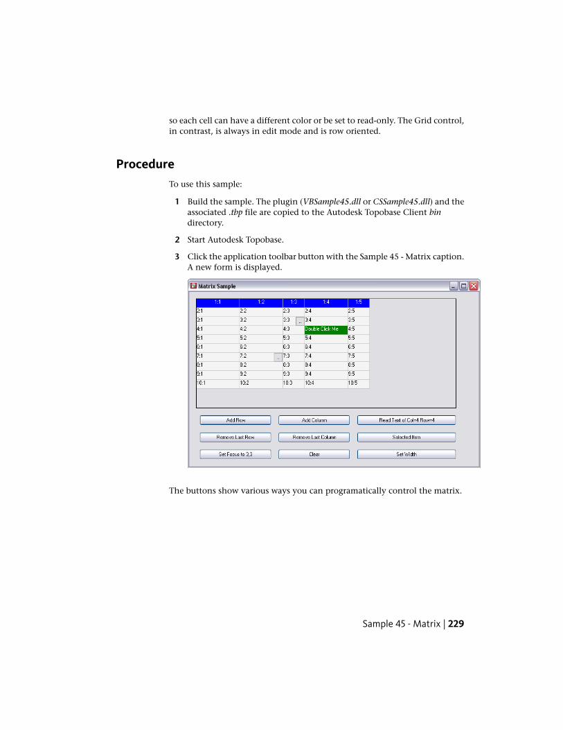
so each cell can have a different color or be set to read-only. The Grid control,in contrast, is always in edit mode and is row oriented.
ProcedureTo use this sample:
1 Build the sample. The plugin (VBSample45.dll or CSSample45.dll) and theassociated .tbp file are copied to the Autodesk Topobase Client bindirectory.
2 Start Autodesk Topobase.
3 Click the application toolbar button with the Sample 45 - Matrix caption.A new form is displayed.
The buttons show various ways you can programatically control the matrix.
Sample 45 - Matrix | 229
Sample 46 - Interaction with a Map
PurposeThis sample shows how a plugin can interact with a map. This sample usesthe TBSAMPLE workspace created by the Sample 01 - Create Structure (page182) application.
ProcedureTo use this sample:
1 Add some points and lines to the TBSAMPLE workspace. This can be doneby using Sample 02 - Read/Write Features (page 191) or within AutodeskTopobase by right-clicking MyPoint and MyLine, choosing Show From,and adding records.
2 Build the sample. The plugin (VBSample46.dll or CSSample46.dll) and theassociated .tbp file are copied to the Autodesk Topobase Client bindirectory.
3 Start Autodesk Topobase and open the TBSAMPLE workspace.
4 Click Generate Graphic.
5 Specify an appropriate viewport and click Generate.
6 Click the document toolbar button with the Sample 46 - Web Interactioncaption. A new form is displayed.
230 | Chapter 6 Developer Samples
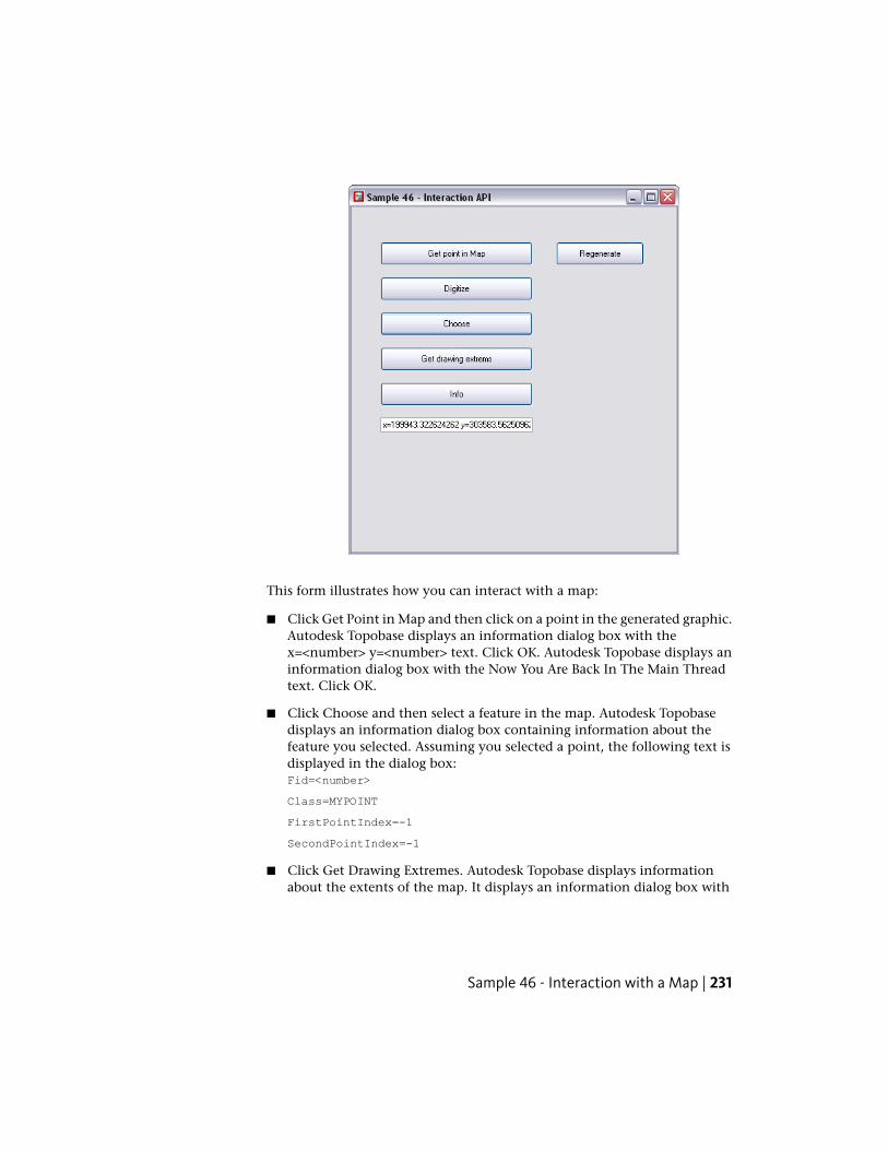
This form illustrates how you can interact with a map:
■ Click Get Point in Map and then click on a point in the generated graphic.Autodesk Topobase displays an information dialog box with thex=<number> y=<number> text. Click OK. Autodesk Topobase displays aninformation dialog box with the Now You Are Back In The Main Threadtext. Click OK.
■ Click Choose and then select a feature in the map. Autodesk Topobasedisplays an information dialog box containing information about thefeature you selected. Assuming you selected a point, the following text isdisplayed in the dialog box:Fid=<number>
Class=MYPOINT
FirstPointIndex=-1
SecondPointIndex=-1
■ Click Get Drawing Extremes. Autodesk Topobase displays informationabout the extents of the map. It displays an information dialog box with
Sample 46 - Interaction with a Map | 231
the Xmin=<number> Ymin=<number> Xmax=<number> Ymax=<number>text. Click OK.
■ Click Info and then click one point in the map. Press Enter. AutodeskTopobase displays an information dialog box with the Fid=<number> text.Click OK.
■ Click Info. Click anywhere in the map, drag the cursor to form a selectionrectangle around a set of points and click. Press Enter. Autodesk Topobasedisplays an information dialog box with the Fid=<number> text. Click OK.Autodesk Topobase displays another information dialog box with theFid=<number> text. Click OK. Autodesk Topobase continues to displayinformation dialog boxes until the feature class identifier for each of thepoints selected have all been displayed.
Sample 47 - Application Options
PurposeThis sample shows how to create your own application-related option forms.
ProcedureTo use this sample:
1 Build the sample. The plugin (VBSample47.dll or CSSample47.dll) and theassociated .tbp file are copied to the Autodesk Topobase Client bindirectory.
2 Start Autodesk Topobase.
3 Click Setup ➤ Topobase Application Options.
4 In the tree, click MyOptions or My Optionpage 2. The new option formsare shown.
232 | Chapter 6 Developer Samples
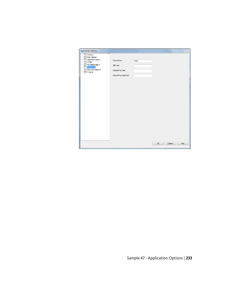
Sample 47 - Application Options | 233
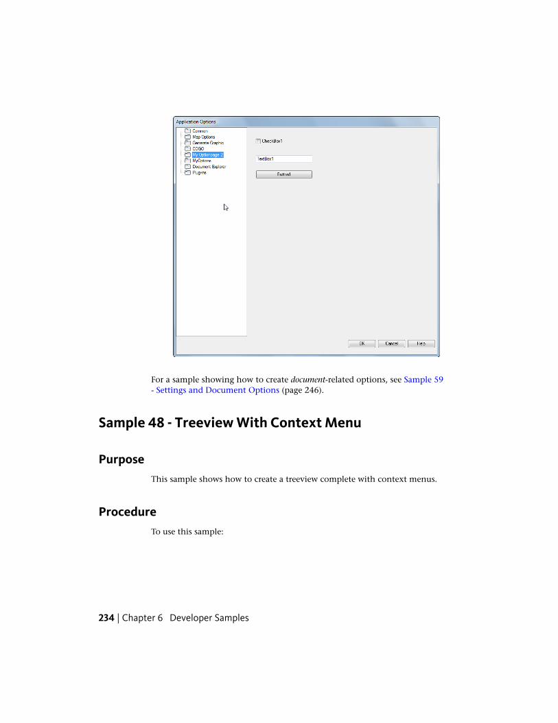
For a sample showing how to create document-related options, see Sample 59- Settings and Document Options (page 246).
Sample 48 - Treeview With Context Menu
PurposeThis sample shows how to create a treeview complete with context menus.
ProcedureTo use this sample:
234 | Chapter 6 Developer Samples
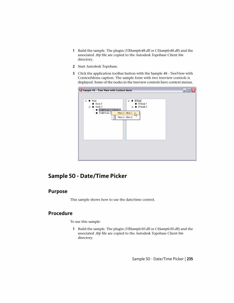
1 Build the sample. The plugin (VBSample48.dll or CSSample48.dll) and theassociated .tbp file are copied to the Autodesk Topobase Client bindirectory.
2 Start Autodesk Topobase.
3 Click the application toolbar button with the Sample 48 - TreeView withContextMenu caption. The sample form with two treeview controls isdisplayed. Some of the nodes in the treeview controls have context menus.
Sample 50 - Date/Time Picker
PurposeThis sample shows how to use the date/time control.
ProcedureTo use this sample:
1 Build the sample. The plugin (VBSample50.dll or CSSample50.dll) and theassociated .tbp file are copied to the Autodesk Topobase Client bindirectory.
Sample 50 - Date/Time Picker | 235
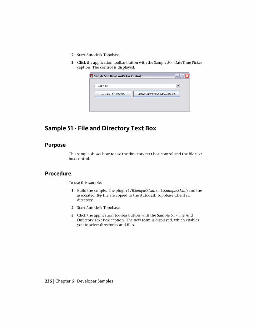
2 Start Autodesk Topobase.
3 Click the application toolbar button with the Sample 50 - DateTime Pickercaption. The control is displayed.
Sample 51 - File and Directory Text Box
PurposeThis sample shows how to use the directory text box control and the file textbox control.
ProcedureTo use this sample:
1 Build the sample. The plugin (VBSample51.dll or CSSample51.dll) and theassociated .tbp file are copied to the Autodesk Topobase Client bindirectory.
2 Start Autodesk Topobase.
3 Click the application toolbar button with the Sample 51 - File AndDirectory Text Box caption. The new form is displayed, which enablesyou to select directories and files.
236 | Chapter 6 Developer Samples
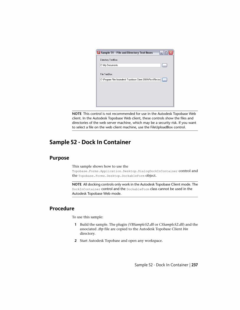
NOTE This control is not recommended for use in the Autodesk Topobase Webclient. In the Autodesk Topobase Web client, these controls show the files anddirectories of the web server machine, which may be a security risk. If you wantto select a file on the web client machine, use the FileUploadBox control.
Sample 52 - Dock In Container
PurposeThis sample shows how to use theTopobase.Forms.Application.Desktop.DialogDockInContainer control andthe Topobase.Forms.Desktop.DockableForm object.
NOTE All docking controls only work in the Autodesk Topobase Client mode. TheDockInContainer control and the DockableForm class cannot be used in theAutodesk Topobase Web mode.
ProcedureTo use this sample:
1 Build the sample. The plugin (VBSample52.dll or CSSample52.dll) and theassociated .tbp file are copied to the Autodesk Topobase Client bindirectory.
2 Start Autodesk Topobase and open any workspace.
Sample 52 - Dock In Container | 237
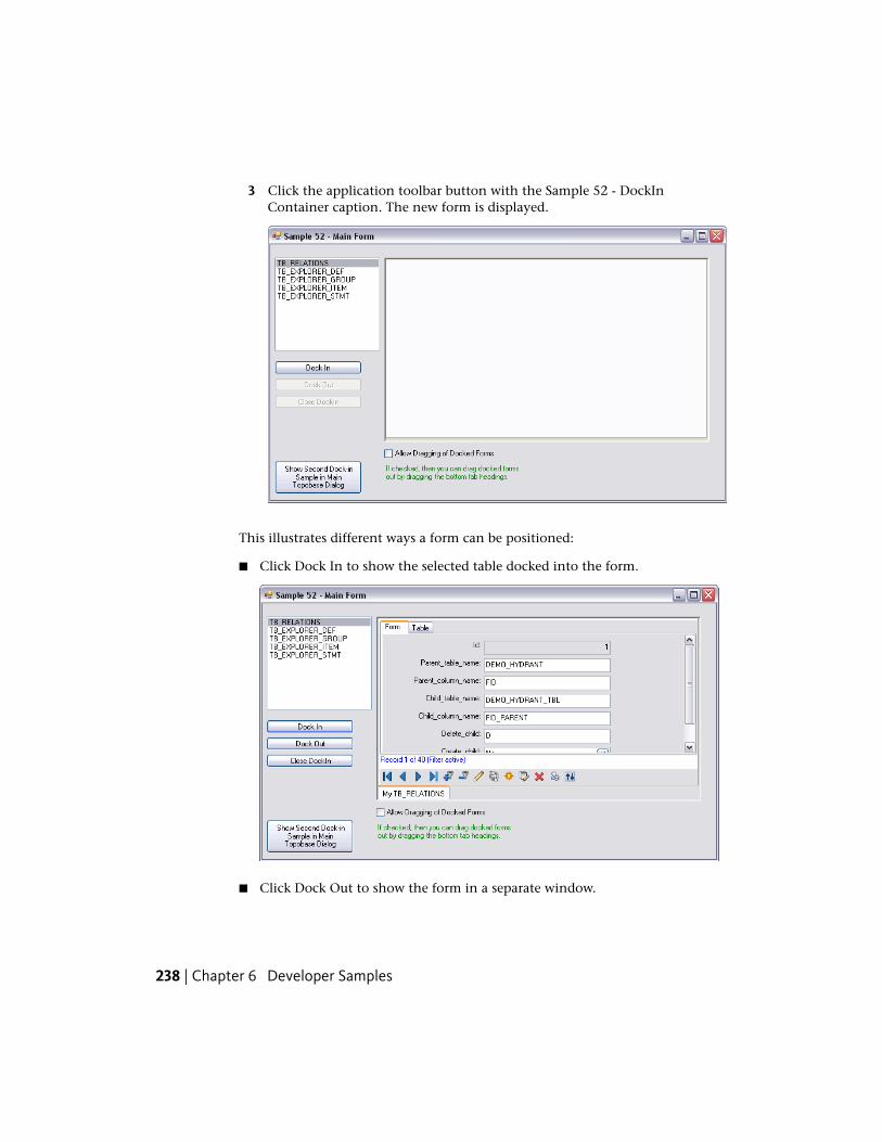
3 Click the application toolbar button with the Sample 52 - DockInContainer caption. The new form is displayed.
This illustrates different ways a form can be positioned:
■ Click Dock In to show the selected table docked into the form.
■ Click Dock Out to show the form in a separate window.
238 | Chapter 6 Developer Samples
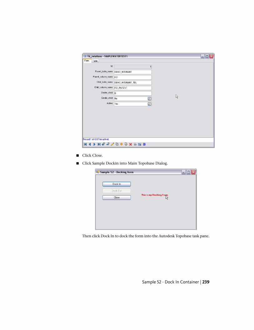
■ Click Close.
■ Click Sample Dockin into Main Topobase Dialog.
Then click Dock In to dock the form into the Autodesk Topobase task pane.
Sample 52 - Dock In Container | 239
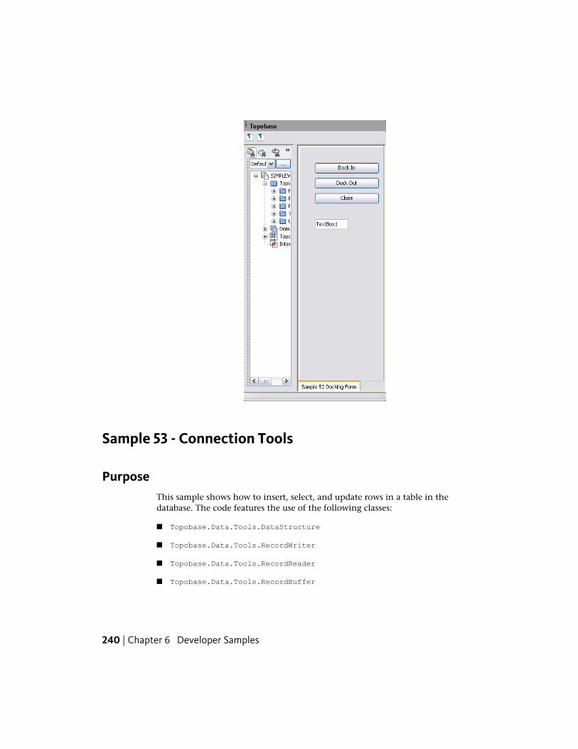
Sample 53 - Connection Tools
PurposeThis sample shows how to insert, select, and update rows in a table in thedatabase. The code features the use of the following classes:
■ Topobase.Data.Tools.DataStructure
■ Topobase.Data.Tools.RecordWriter
■ Topobase.Data.Tools.RecordReader
■ Topobase.Data.Tools.RecordBuffer
240 | Chapter 6 Developer Samples
■ Topobase.Data.Tools.ConnectionTools
■ Topobase.Data.Tools.SqlExport
ProcedureTo use this sample:
1 Build the sample. The plugin (VBSample53.dll or CSSample53.dll) and theassociated .tbp file are copied to the Autodesk Topobase Client bindirectory.
2 Start Autodesk Topobase and open the TBSAMPLE workspace.
3 Click the application toolbar button with the Sample 53 - ConnectionTools caption. The new form is displayed.
NOTE If you have run the sample previously (you can use Step 6 to determineif the table exists) and want to start again from the beginning, you mustremove the sample_person table from the database. In an Oracle SQL*Plussession enter the following commands:
connect tbsample/avs
drop table sample_person cascade constraints;
Sample 53 - Connection Tools | 241
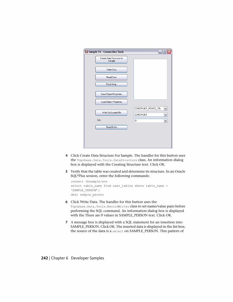
4 Click Create Data Structure For Sample. The handler for this button usesthe Topobase.Data.Tools.DataStructure class. An information dialogbox is displayed with the Creating Structure text. Click OK.
5 Verify that the table was created and determine its structure. In an OracleSQL*Plus session, enter the following commands:
connect tbsample/avs
select table_name from user_tables where table_name =
‘SAMPLE_PERSON’;
desc sample_person
6 Click Write Data. The handler for this button uses theTopobase.Data.Tools.RecordWriter class to set name/value pairs beforeperforming the SQL command. An information dialog box is displayedwith the There are 0 values in SAMPLE_PERSON text. Click OK.
7 A message box is displayed with a SQL statement for an insertion intoSAMPLE_PERSON. Click OK. The inserted data is displayed in the list box;the source of the data is a select on SAMPLE_PERSON. This pattern of
242 | Chapter 6 Developer Samples
events is repeated several times with some of the SQL statements beinginsertions and some being updates.
8 Click Read Data. The handler for this button uses theTopobase.Data.Tools.RecordReader class. Some data from each row inthe SAMPLE_PERSON table is displayed in the list box.
9 Click Read Array. The handler for this button uses theTopobase.Data.Tools.RecordBuffer and theTopobase.Data.Tools.ConnectionTools classes. A message box is displayedwith the Gabi del la Blub has Size 0.58 text. Click OK.
10 Click Save Object Properties. The handler for this button uses theTopobase.Data.Tools.RecordWriter class to serialize properties extractedfrom an object before executing the insert SQL statement.
11 Click Load Object Properties. The handler for this button uses theTopobase.Data.Tools.RecordReader class to select a row fromSAMPLE_PERSON and deserialize the properties to create an object. Amessage box is displayed with information extracted from the object.Click OK.
12 Click Write SQL Loader File. The handler for this button uses theTopobase.Data.Tools.SqlExport class to extract rows fromSAMPLE_PERSON and write them to a file. A text editor window isdisplayed displaying the extracted information. Close the window.
13 Click Read Buffer. The handler for this button usesTopobase.Data.Tools.RecordReader class to select a row fromSAMPLE_PERSON, uses the select results to create an object, displays twoof the object’s properties in a message box, changes one of the objectproperties that was displayed and then uses theTopobase.Data.Tools.RecordWriter class to extract the object propertiesand update the corresponding row in the SAMPLE_PERSON table. Finally,it displays the updated row in the list box.
Sample 55 - Drop Down Buttons
PurposeThis sample shows how to add drop down lists.
Sample 55 - Drop Down Buttons | 243
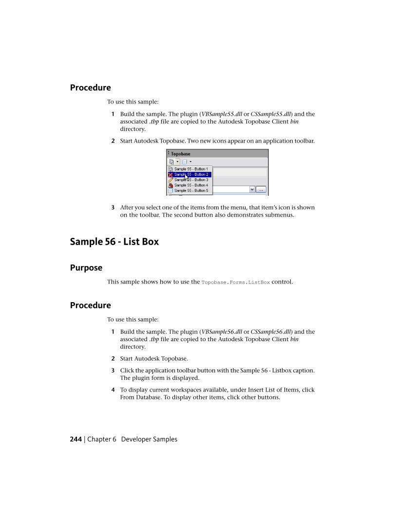
ProcedureTo use this sample:
1 Build the sample. The plugin (VBSample55.dll or CSSample55.dll) and theassociated .tbp file are copied to the Autodesk Topobase Client bindirectory.
2 Start Autodesk Topobase. Two new icons appear on an application toolbar.
3 After you select one of the items from the menu, that item’s icon is shownon the toolbar. The second button also demonstrates submenus.
Sample 56 - List Box
PurposeThis sample shows how to use the Topobase.Forms.ListBox control.
ProcedureTo use this sample:
1 Build the sample. The plugin (VBSample56.dll or CSSample56.dll) and theassociated .tbp file are copied to the Autodesk Topobase Client bindirectory.
2 Start Autodesk Topobase.
3 Click the application toolbar button with the Sample 56 - Listbox caption.The plugin form is displayed.
4 To display current workspaces available, under Insert List of Items, clickFrom Database. To display other items, click other buttons.
244 | Chapter 6 Developer Samples
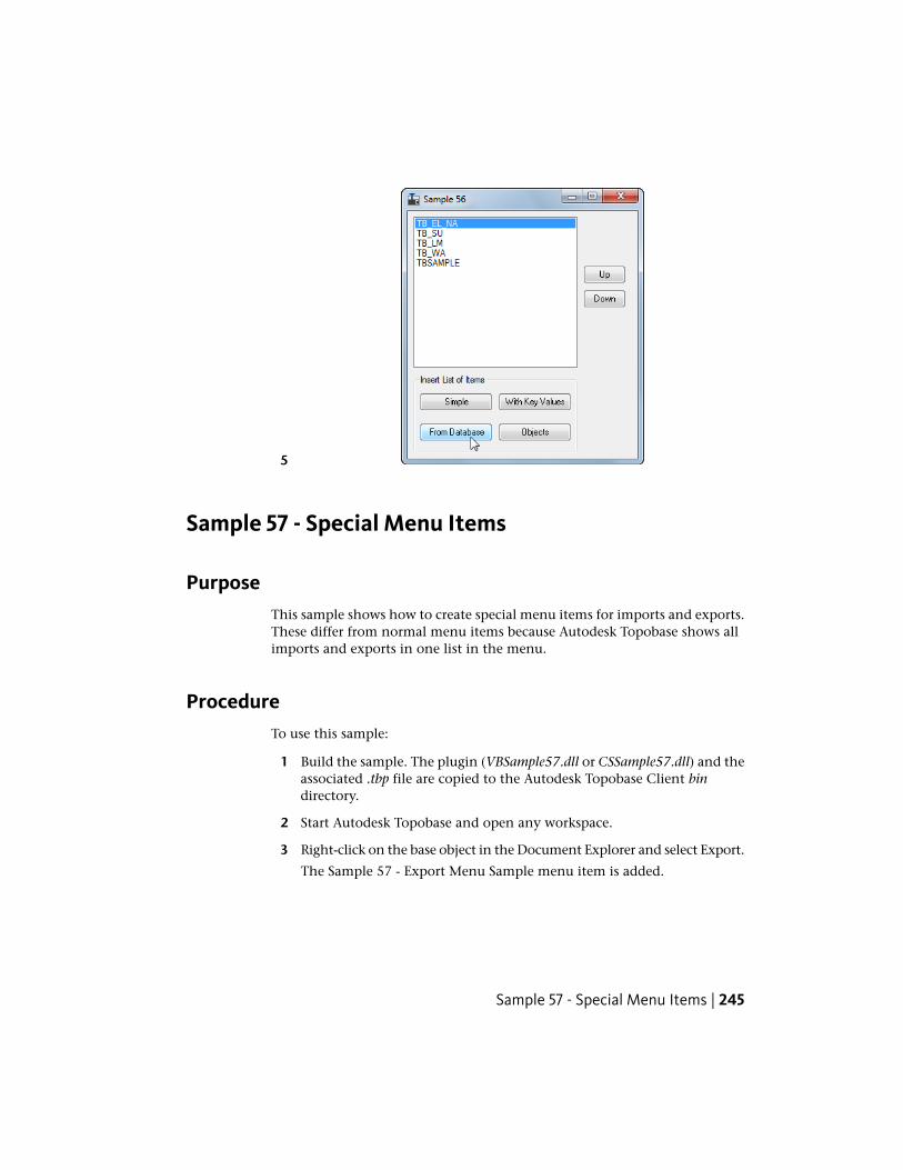
5
Sample 57 - Special Menu Items
PurposeThis sample shows how to create special menu items for imports and exports.These differ from normal menu items because Autodesk Topobase shows allimports and exports in one list in the menu.
ProcedureTo use this sample:
1 Build the sample. The plugin (VBSample57.dll or CSSample57.dll) and theassociated .tbp file are copied to the Autodesk Topobase Client bindirectory.
2 Start Autodesk Topobase and open any workspace.
3 Right-click on the base object in the Document Explorer and select Export.
The Sample 57 - Export Menu Sample menu item is added.
Sample 57 - Special Menu Items | 245
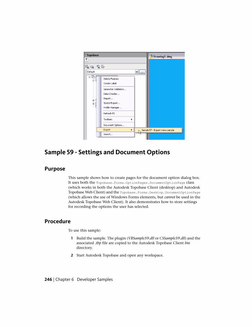
Sample 59 - Settings and Document Options
PurposeThis sample shows how to create pages for the document option dialog box.It uses both the Topobase.Forms.OptionPages.DocumentOptionPage class(which works in both the Autodesk Topobase Client (desktop) and AutodeskTopobase Web Client) and the Topobase.Forms.Desktop.DocumentOptionPage(which allows the use of Windows Forms elements, but cannot be used in theAutodesk Topobase Web Client). It also demonstrates how to store settingsfor recording the options the user has selected.
ProcedureTo use this sample:
1 Build the sample. The plugin (VBSample59.dll or CSSample59.dll) and theassociated .tbp file are copied to the Autodesk Topobase Client bindirectory.
2 Start Autodesk Topobase and open any workspace.
246 | Chapter 6 Developer Samples
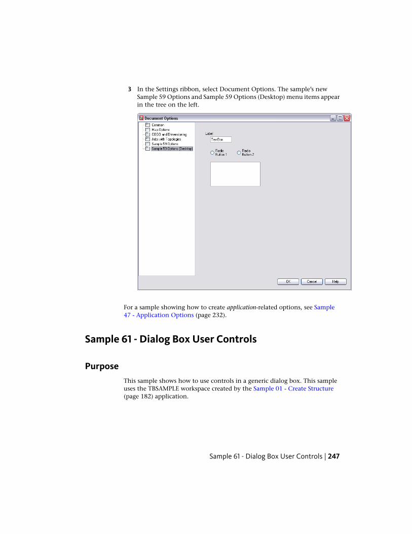
3 In the Settings ribbon, select Document Options. The sample’s newSample 59 Options and Sample 59 Options (Desktop) menu items appearin the tree on the left.
For a sample showing how to create application-related options, see Sample47 - Application Options (page 232).
Sample 61 - Dialog Box User Controls
PurposeThis sample shows how to use controls in a generic dialog box. This sampleuses the TBSAMPLE workspace created by the Sample 01 - Create Structure(page 182) application.
Sample 61 - Dialog Box User Controls | 247
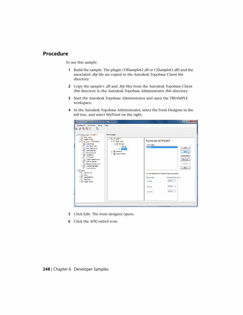
ProcedureTo use this sample:
1 Build the sample. The plugin (VBSample61.dll or CSSample61.dll) and theassociated .tbp file are copied to the Autodesk Topobase Client bindirectory.
2 Copy the sample’s .dll and .tbp files from the Autodesk Topobase Client/bin directory to the Autodesk Topobase Administrator /bin directory.
3 Start the Autodesk Topobase Administrator and open the TBSAMPLEworkspace.
4 In the Autodesk Topobase Administrator, select the Form Designer in theleft tree, and select MyPoint on the right.
5 Click Edit. The form designer opens.
6 Click the APIControl icon.
248 | Chapter 6 Developer Samples
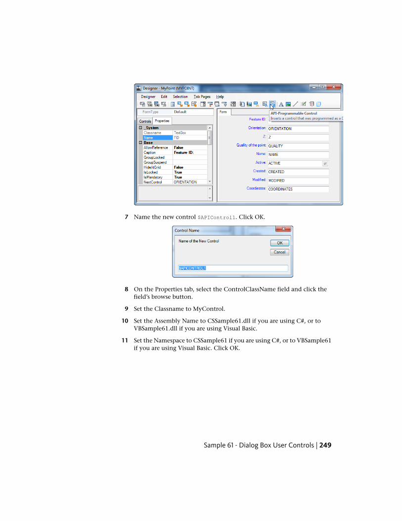
7 Name the new control $APIControl1. Click OK.
8 On the Properties tab, select the ControlClassName field and click thefield’s browse button.
9 Set the Classname to MyControl.
10 Set the Assembly Name to CSSample61.dll if you are using C#, or toVBSample61.dll if you are using Visual Basic.
11 Set the Namespace to CSSample61 if you are using C#, or to VBSample61if you are using Visual Basic. Click OK.
Sample 61 - Dialog Box User Controls | 249
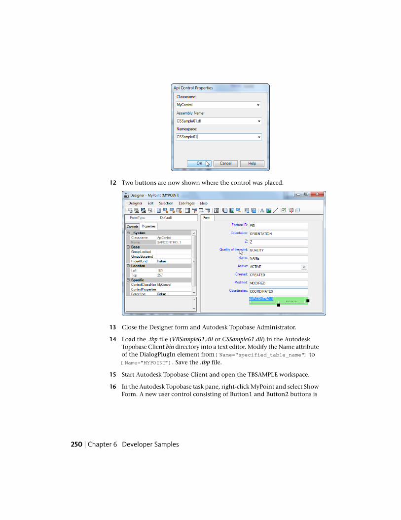
12 Two buttons are now shown where the control was placed.
13 Close the Designer form and Autodesk Topobase Administrator.
14 Load the .tbp file (VBSample61.dll or CSSample61.dll) in the AutodeskTopobase Client bin directory into a text editor. Modify the Name attributeof the DialogPlugIn element from [Name="specified_table_name"] to[Name="MYPOINT"]. Save the .tbp file.
15 Start Autodesk Topobase Client and open the TBSAMPLE workspace.
16 In the Autodesk Topobase task pane, right-click MyPoint and select ShowForm. A new user control consisting of Button1 and Button2 buttons is
250 | Chapter 6 Developer Samples
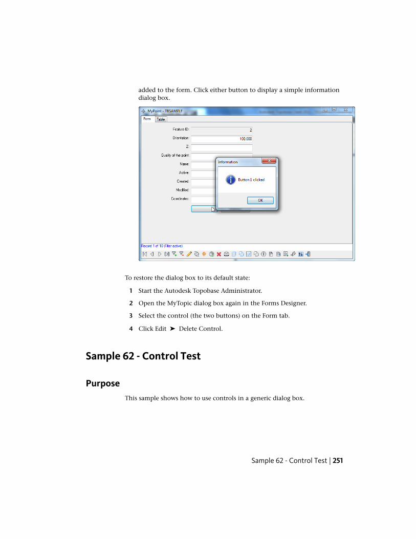
added to the form. Click either button to display a simple informationdialog box.
To restore the dialog box to its default state:
1 Start the Autodesk Topobase Administrator.
2 Open the MyTopic dialog box again in the Forms Designer.
3 Select the control (the two buttons) on the Form tab.
4 Click Edit ➤ Delete Control.
Sample 62 - Control Test
PurposeThis sample shows how to use controls in a generic dialog box.
Sample 62 - Control Test | 251
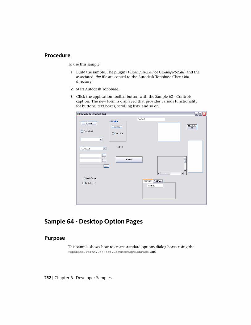
ProcedureTo use this sample:
1 Build the sample. The plugin (VBSample62.dll or CSSample62.dll) and theassociated .tbp file are copied to the Autodesk Topobase Client bindirectory.
2 Start Autodesk Topobase.
3 Click the application toolbar button with the Sample 62 - Controlscaption. The new form is displayed that provides various functionalityfor buttons, text boxes, scrolling lists, and so on.
Sample 64 - Desktop Option Pages
PurposeThis sample shows how to create standard options dialog boxes using theTopobase.Forms.Desktop.DocumentOptionPage and
252 | Chapter 6 Developer Samples
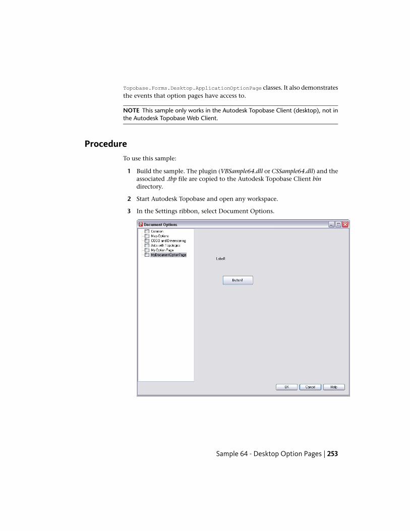
Topobase.Forms.Desktop.ApplicationOptionPage classes. It also demonstratesthe events that option pages have access to.
NOTE This sample only works in the Autodesk Topobase Client (desktop), not inthe Autodesk Topobase Web Client.
ProcedureTo use this sample:
1 Build the sample. The plugin (VBSample64.dll or CSSample64.dll) and theassociated .tbp file are copied to the Autodesk Topobase Client bindirectory.
2 Start Autodesk Topobase and open any workspace.
3 In the Settings ribbon, select Document Options.
Sample 64 - Desktop Option Pages | 253
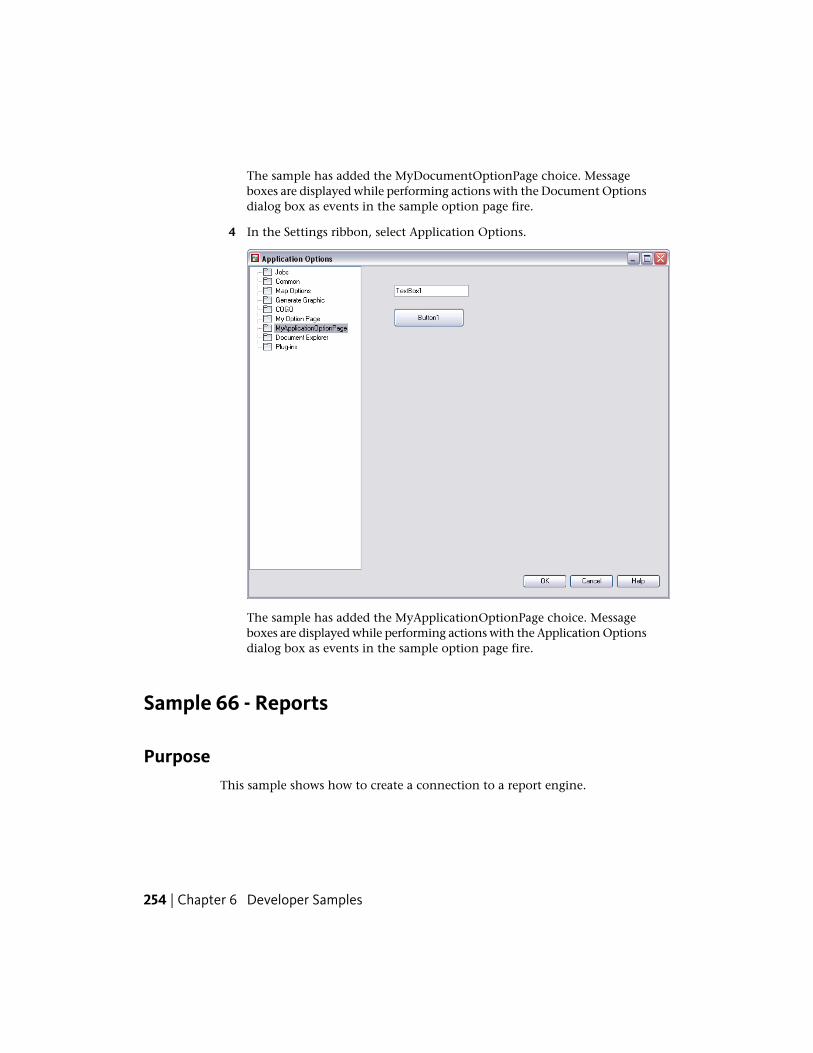
The sample has added the MyDocumentOptionPage choice. Messageboxes are displayed while performing actions with the Document Optionsdialog box as events in the sample option page fire.
4 In the Settings ribbon, select Application Options.
The sample has added the MyApplicationOptionPage choice. Messageboxes are displayed while performing actions with the Application Optionsdialog box as events in the sample option page fire.
Sample 66 - Reports
PurposeThis sample shows how to create a connection to a report engine.
254 | Chapter 6 Developer Samples
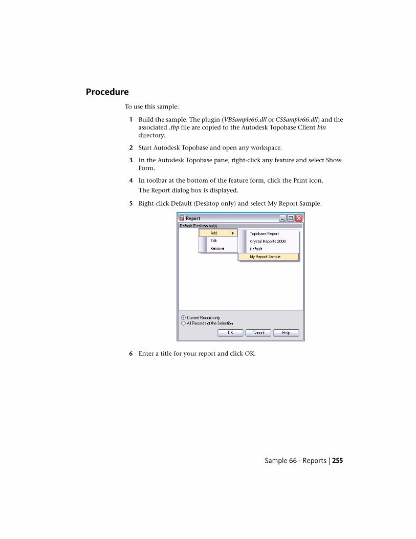
ProcedureTo use this sample:
1 Build the sample. The plugin (VBSample66.dll or CSSample66.dll) and theassociated .tbp file are copied to the Autodesk Topobase Client bindirectory.
2 Start Autodesk Topobase and open any workspace.
3 In the Autodesk Topobase pane, right-click any feature and select ShowForm.
4 In toolbar at the bottom of the feature form, click the Print icon.
The Report dialog box is displayed.
5 Right-click Default (Desktop only) and select My Report Sample.
6 Enter a title for your report and click OK.
Sample 66 - Reports | 255
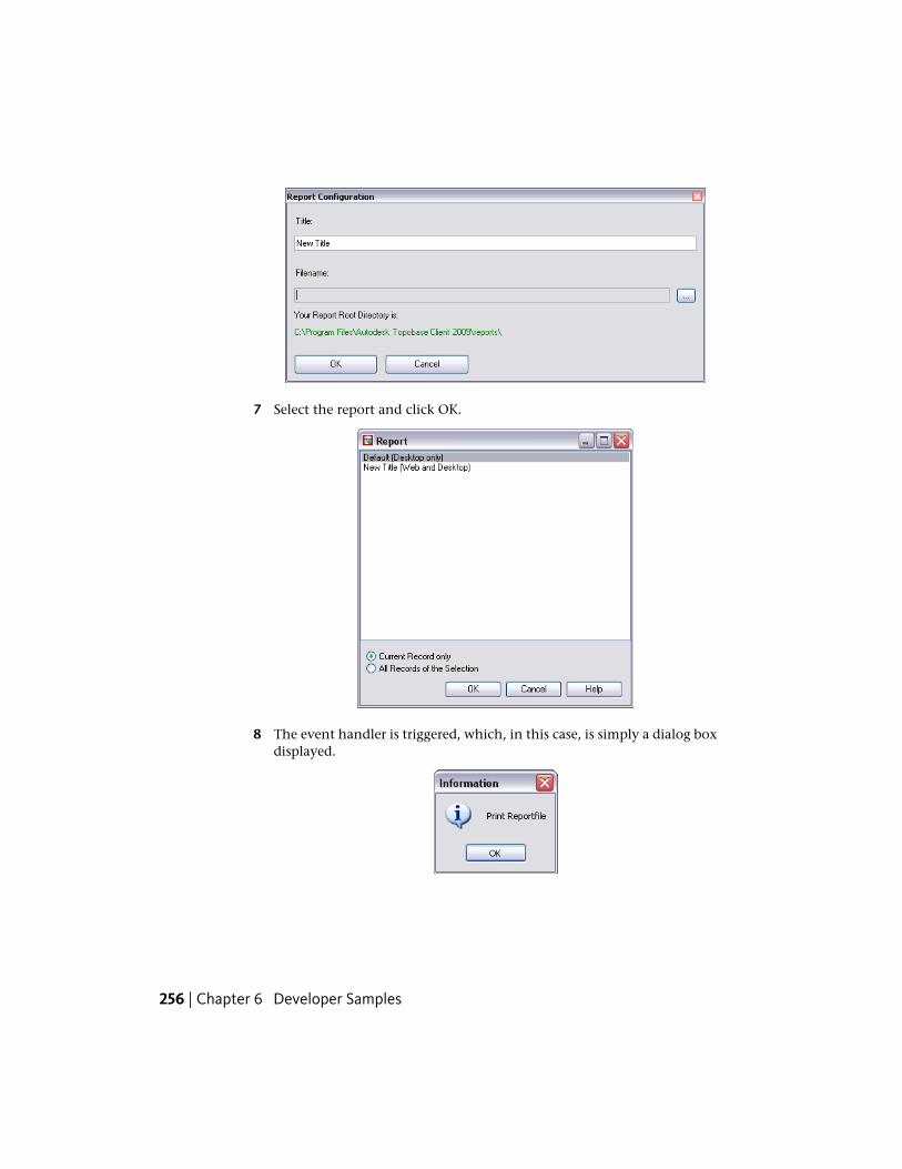
7 Select the report and click OK.
8 The event handler is triggered, which, in this case, is simply a dialog boxdisplayed.
256 | Chapter 6 Developer Samples
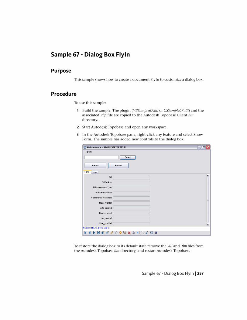
Sample 67 - Dialog Box FlyIn
PurposeThis sample shows how to create a document FlyIn to customize a dialog box.
ProcedureTo use this sample:
1 Build the sample. The plugin (VBSample67.dll or CSSample67.dll) and theassociated .tbp file are copied to the Autodesk Topobase Client bindirectory.
2 Start Autodesk Topobase and open any workspace.
3 In the Autodesk Topobase pane, right-click any feature and select ShowForm. The sample has added new controls to the dialog box.
To restore the dialog box to its default state remove the .dll and .tbp files fromthe Autodesk Topobase bin directory, and restart Autodesk Topobase.
Sample 67 - Dialog Box FlyIn | 257
Sample 68 - Option Page With Tree Nodes
PurposeThis sample shows how to add an item with sub nodes to the documentoptions tree.
ProcedureTo use this sample:
1 Build the sample. The plugin (VBSample68.dll or CSSample68.dll) and theassociated .tbp file are copied to the Autodesk Topobase Client bindirectory.
2 Start Autodesk Topobase and open any workspace.
3 In the Settings ribbon, select Application Options. The sample has addeda new item, My Options Page, to the treeview with three different nodes.
258 | Chapter 6 Developer Samples
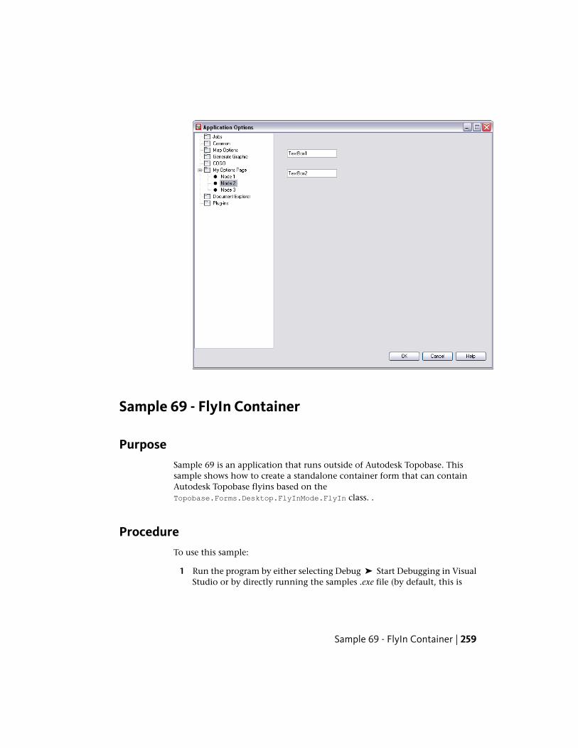
Sample 69 - FlyIn Container
PurposeSample 69 is an application that runs outside of Autodesk Topobase. Thissample shows how to create a standalone container form that can containAutodesk Topobase flyins based on theTopobase.Forms.Desktop.FlyInMode.FlyIn class. .
ProcedureTo use this sample:
1 Run the program by either selecting Debug ➤ Start Debugging in VisualStudio or by directly running the samples .exe file (by default, this is
Sample 69 - FlyIn Container | 259
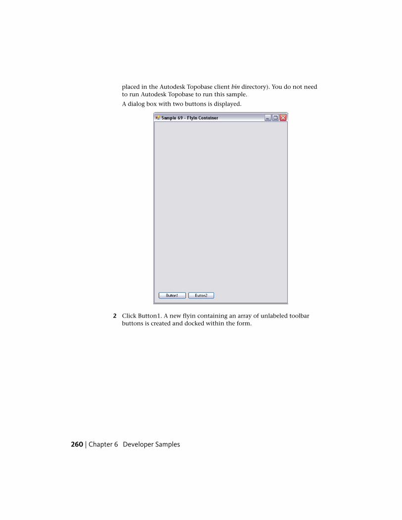
placed in the Autodesk Topobase client bin directory). You do not needto run Autodesk Topobase to run this sample.
A dialog box with two buttons is displayed.
2 Click Button1. A new flyin containing an array of unlabeled toolbarbuttons is created and docked within the form.
260 | Chapter 6 Developer Samples
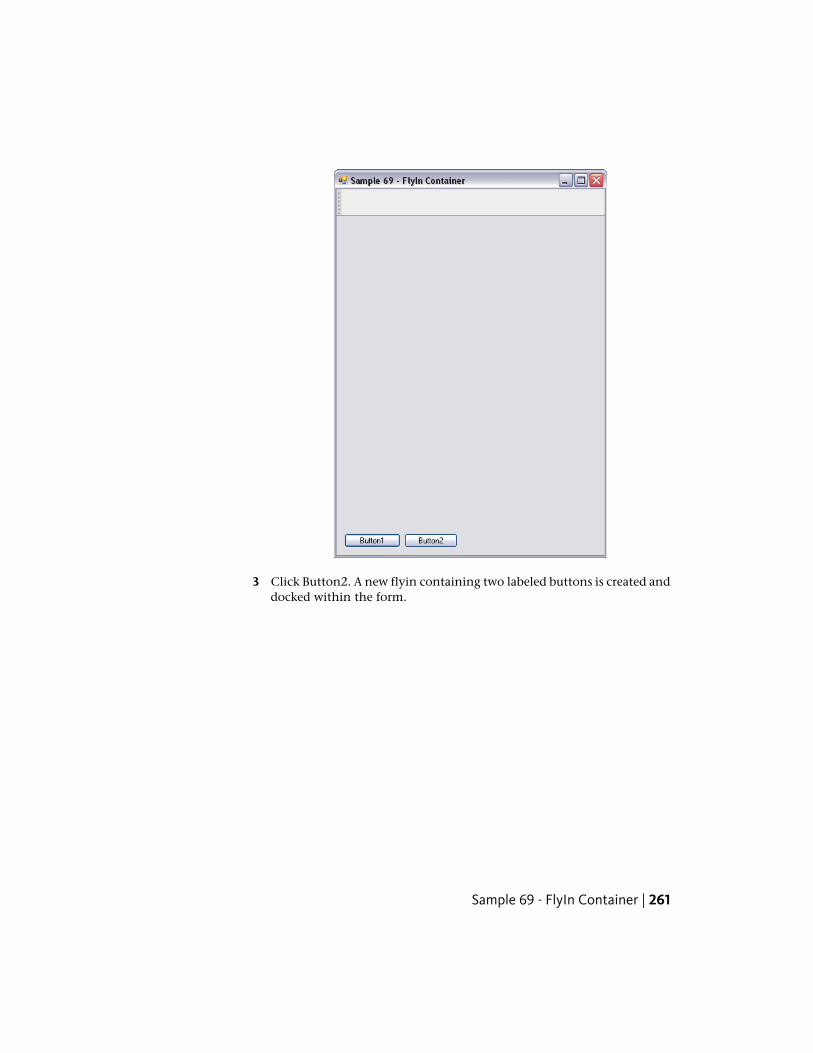
3 Click Button2. A new flyin containing two labeled buttons is created anddocked within the form.
Sample 69 - FlyIn Container | 261
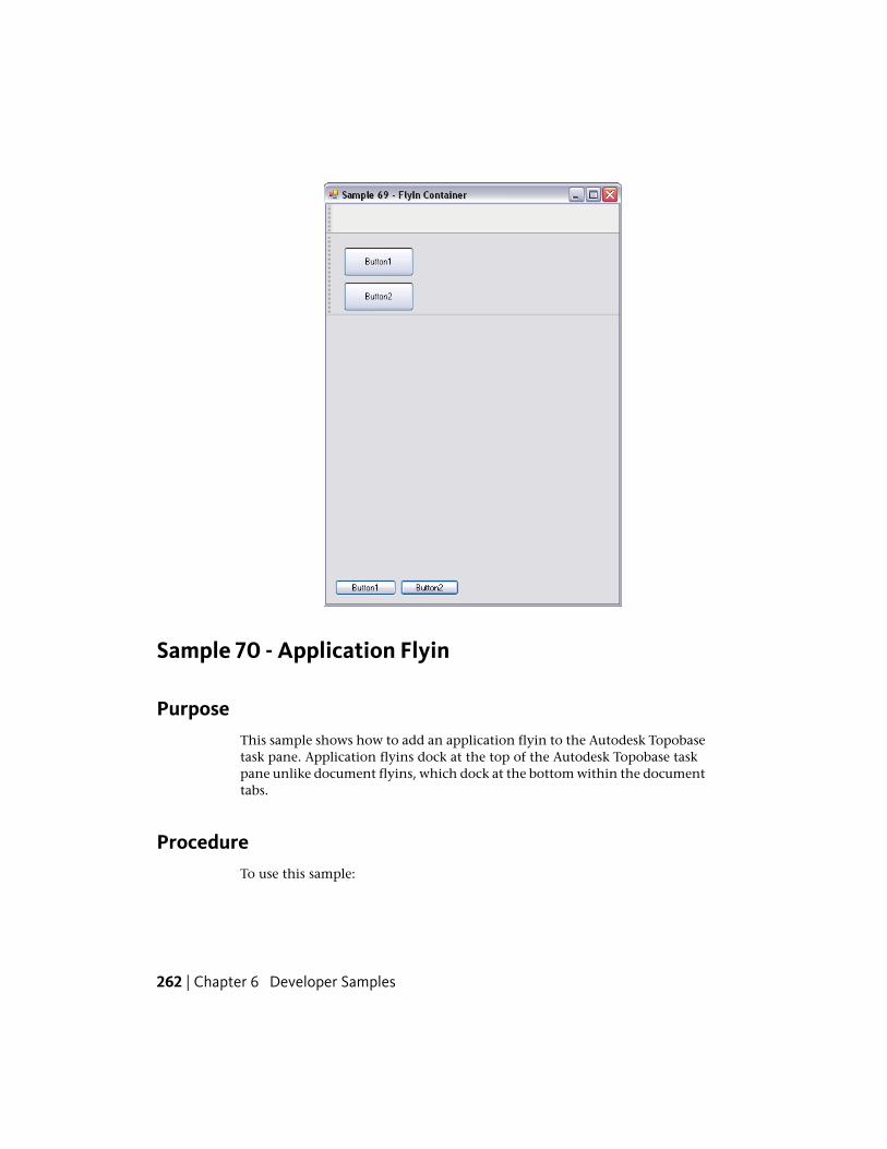
Sample 70 - Application Flyin
PurposeThis sample shows how to add an application flyin to the Autodesk Topobasetask pane. Application flyins dock at the top of the Autodesk Topobase taskpane unlike document flyins, which dock at the bottom within the documenttabs.
ProcedureTo use this sample:
262 | Chapter 6 Developer Samples
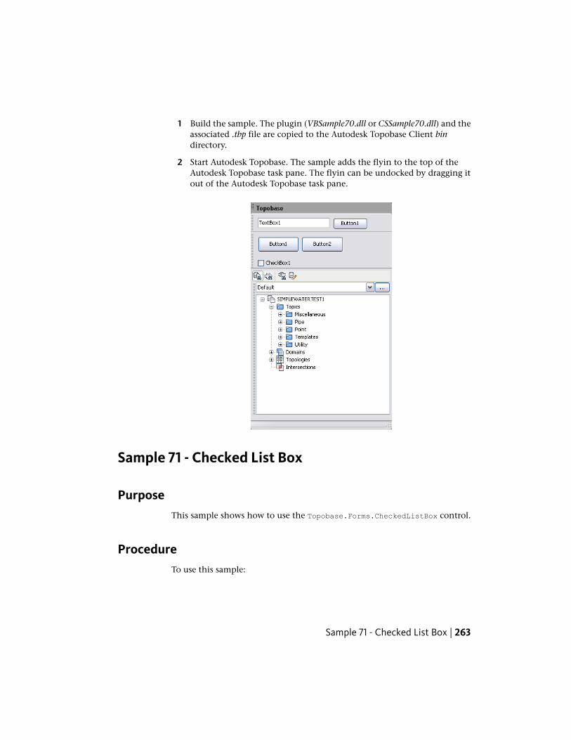
1 Build the sample. The plugin (VBSample70.dll or CSSample70.dll) and theassociated .tbp file are copied to the Autodesk Topobase Client bindirectory.
2 Start Autodesk Topobase. The sample adds the flyin to the top of theAutodesk Topobase task pane. The flyin can be undocked by dragging itout of the Autodesk Topobase task pane.
Sample 71 - Checked List Box
PurposeThis sample shows how to use the Topobase.Forms.CheckedListBox control.
ProcedureTo use this sample:
Sample 71 - Checked List Box | 263
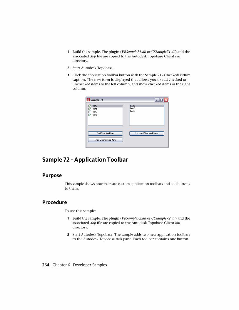
1 Build the sample. The plugin (VBSample71.dll or CSSample71.dll) and theassociated .tbp file are copied to the Autodesk Topobase Client bindirectory.
2 Start Autodesk Topobase.
3 Click the application toolbar button with the Sample 71 - CheckedListBoxcaption. The new form is displayed that allows you to add checked orunchecked items to the left column, and show checked items in the rightcolumn.
Sample 72 - Application Toolbar
PurposeThis sample shows how to create custom application toolbars and add buttonsto them.
ProcedureTo use this sample:
1 Build the sample. The plugin (VBSample72.dll or CSSample72.dll) and theassociated .tbp file are copied to the Autodesk Topobase Client bindirectory.
2 Start Autodesk Topobase. The sample adds two new application toolbarsto the Autodesk Topobase task pane. Each toolbar contains one button.
264 | Chapter 6 Developer Samples
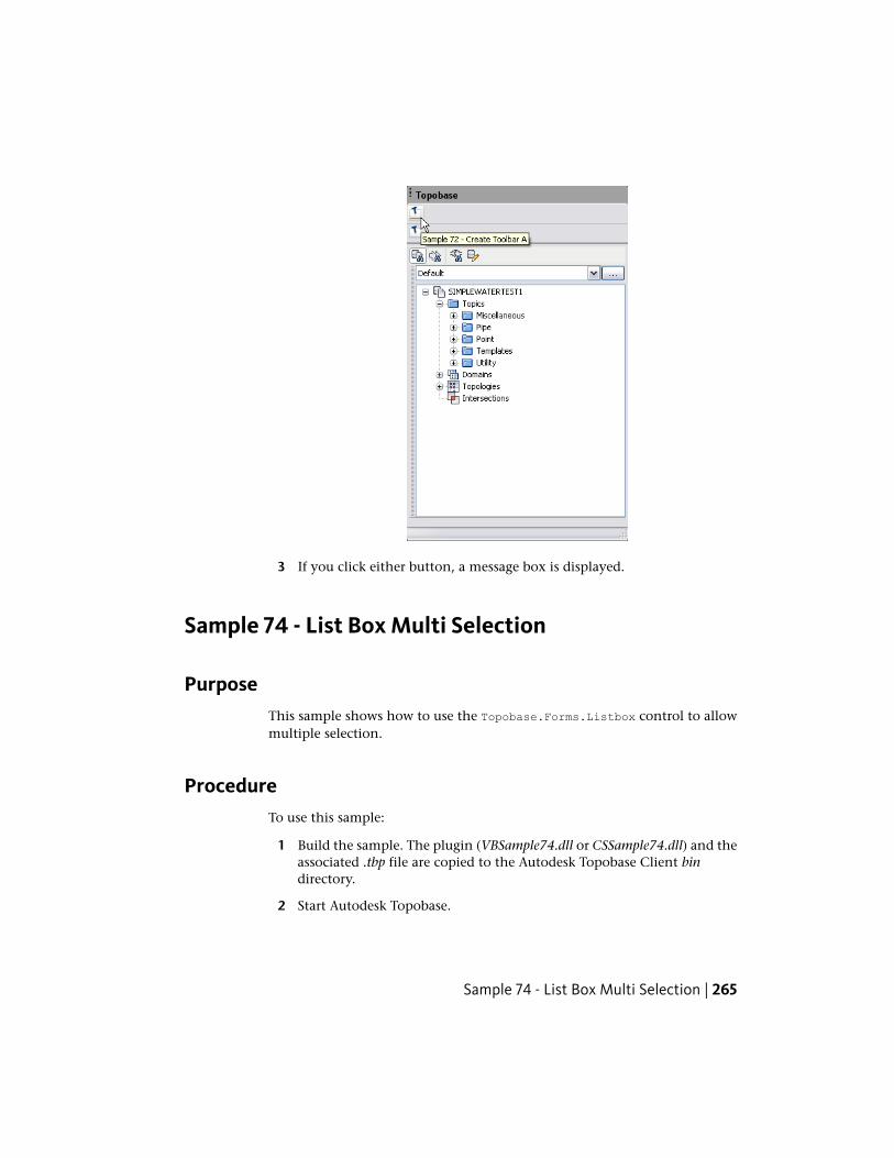
3 If you click either button, a message box is displayed.
Sample 74 - List Box Multi Selection
PurposeThis sample shows how to use the Topobase.Forms.Listbox control to allowmultiple selection.
ProcedureTo use this sample:
1 Build the sample. The plugin (VBSample74.dll or CSSample74.dll) and theassociated .tbp file are copied to the Autodesk Topobase Client bindirectory.
2 Start Autodesk Topobase.
Sample 74 - List Box Multi Selection | 265
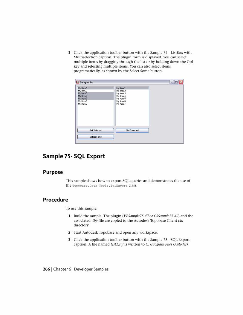
3 Click the application toolbar button with the Sample 74 - ListBox withMultiselection caption. The plugin form is displayed. You can selectmultiple items by dragging through the list or by holding down the Ctrlkey and selecting multiple items. You can also select itemsprogramatically, as shown by the Select Some button.
Sample 75- SQL Export
PurposeThis sample shows how to export SQL queries and demonstrates the use ofthe Topobase.Data.Tools.SqlExport class.
ProcedureTo use this sample:
1 Build the sample. The plugin (VBSample75.dll or CSSample75.dll) and theassociated .tbp file are copied to the Autodesk Topobase Client bindirectory.
2 Start Autodesk Topobase and open any workspace.
3 Click the application toolbar button with the Sample 75 - SQL Exportcaption. A file named test1.sql is written to C:\Program Files\Autodesk
266 | Chapter 6 Developer Samples
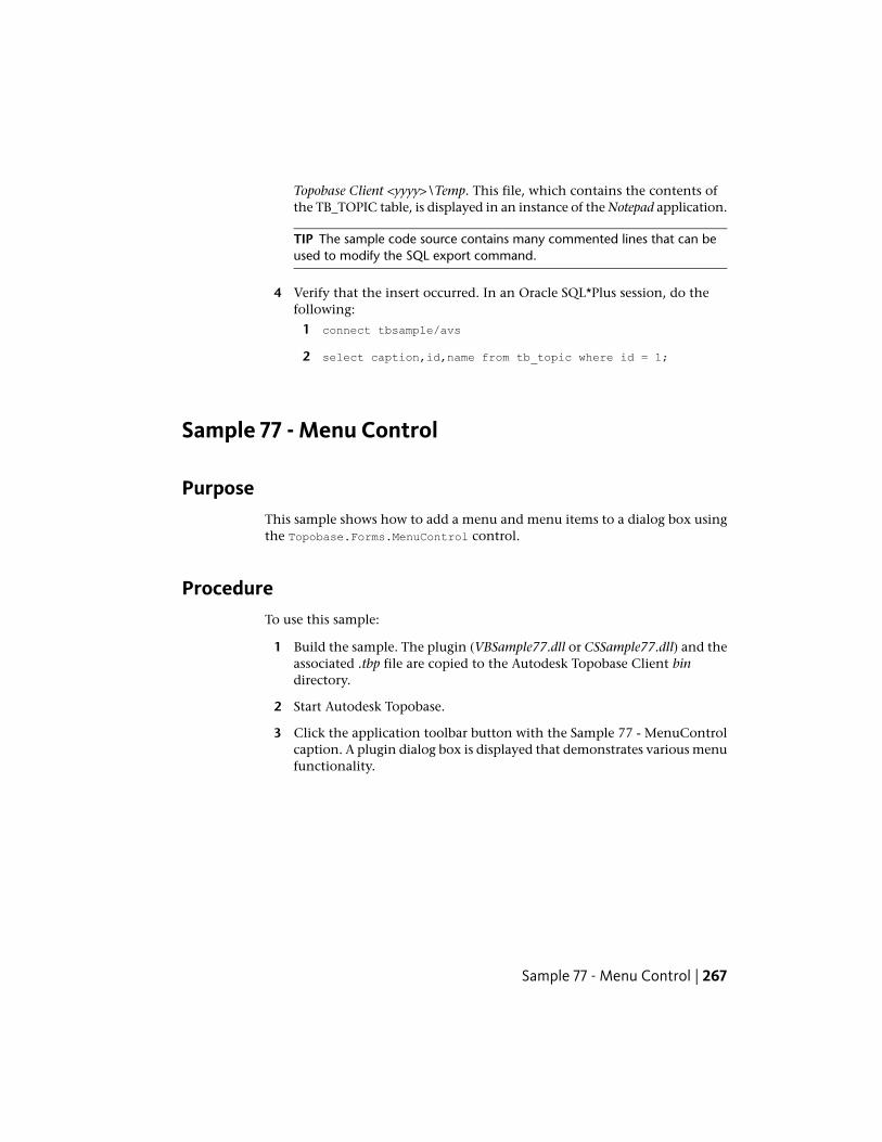
Topobase Client <yyyy>\Temp. This file, which contains the contents ofthe TB_TOPIC table, is displayed in an instance of the Notepad application.
TIP The sample code source contains many commented lines that can beused to modify the SQL export command.
4 Verify that the insert occurred. In an Oracle SQL*Plus session, do thefollowing:
1 connect tbsample/avs
2 select caption,id,name from tb_topic where id = 1;
Sample 77 - Menu Control
PurposeThis sample shows how to add a menu and menu items to a dialog box usingthe Topobase.Forms.MenuControl control.
ProcedureTo use this sample:
1 Build the sample. The plugin (VBSample77.dll or CSSample77.dll) and theassociated .tbp file are copied to the Autodesk Topobase Client bindirectory.
2 Start Autodesk Topobase.
3 Click the application toolbar button with the Sample 77 - MenuControlcaption. A plugin dialog box is displayed that demonstrates various menufunctionality.
Sample 77 - Menu Control | 267
Sample 78 - Web Browser
PurposeThis sample shows how to use a web browser control. Any document that canbe opened by Internet Explorer can be opened by this control and shown inyour form.
ProcedureTo use this sample:
1 Build the sample. The plugin (VBSample78.dll or CSSample78.dll) and theassociated .tbp file are copied to the Autodesk Topobase Client bindirectory.
2 Start Autodesk Topobase.
3 Click the application toolbar button with the Sample 78 - Browser caption.The plugin form is displayed. To display a web site, type a web addressin the text box at the top of the form and click Go.
268 | Chapter 6 Developer Samples
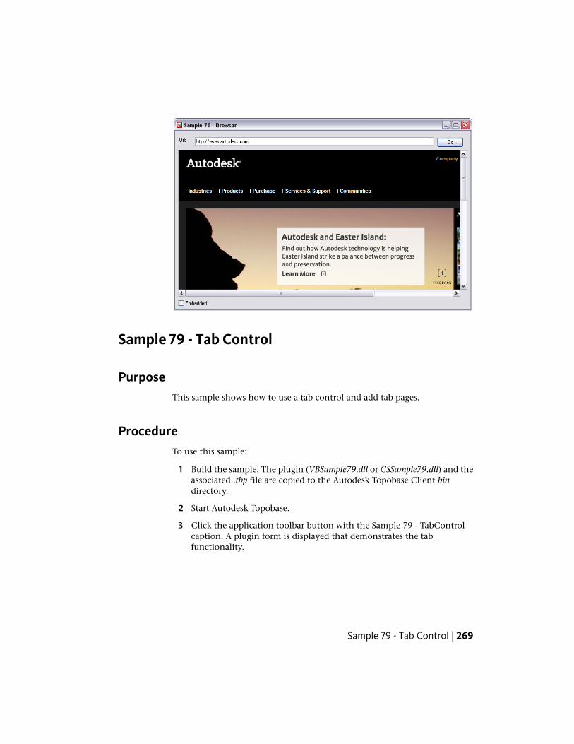
Sample 79 - Tab Control
PurposeThis sample shows how to use a tab control and add tab pages.
ProcedureTo use this sample:
1 Build the sample. The plugin (VBSample79.dll or CSSample79.dll) and theassociated .tbp file are copied to the Autodesk Topobase Client bindirectory.
2 Start Autodesk Topobase.
3 Click the application toolbar button with the Sample 79 - TabControlcaption. A plugin form is displayed that demonstrates the tabfunctionality.
Sample 79 - Tab Control | 269
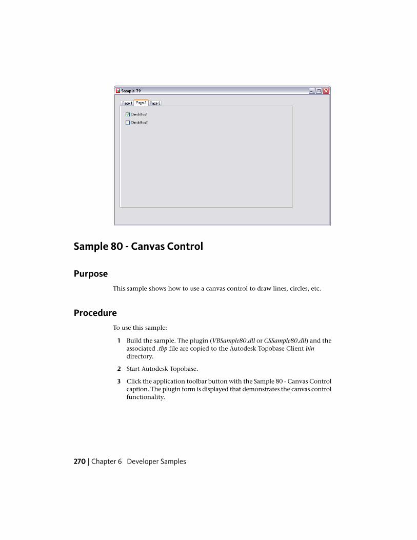
Sample 80 - Canvas Control
PurposeThis sample shows how to use a canvas control to draw lines, circles, etc.
ProcedureTo use this sample:
1 Build the sample. The plugin (VBSample80.dll or CSSample80.dll) and theassociated .tbp file are copied to the Autodesk Topobase Client bindirectory.
2 Start Autodesk Topobase.
3 Click the application toolbar button with the Sample 80 - Canvas Controlcaption. The plugin form is displayed that demonstrates the canvas controlfunctionality.
270 | Chapter 6 Developer Samples
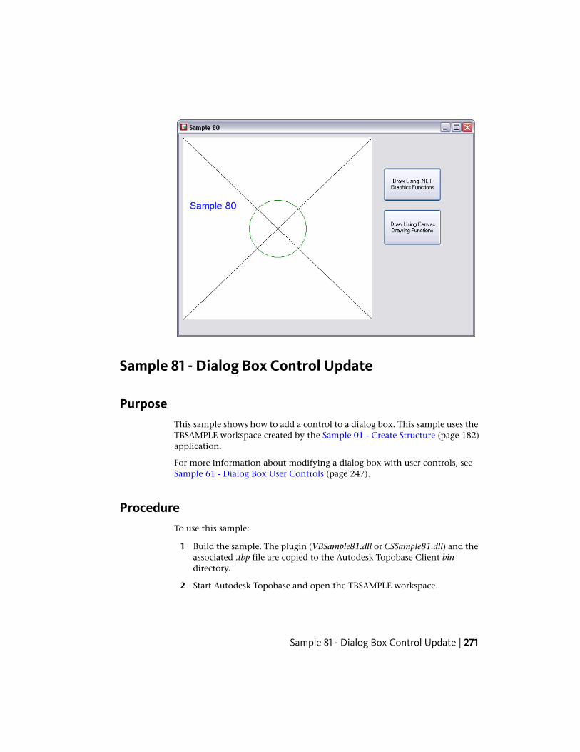
Sample 81 - Dialog Box Control Update
PurposeThis sample shows how to add a control to a dialog box. This sample uses theTBSAMPLE workspace created by the Sample 01 - Create Structure (page 182)application.
For more information about modifying a dialog box with user controls, seeSample 61 - Dialog Box User Controls (page 247).
ProcedureTo use this sample:
1 Build the sample. The plugin (VBSample81.dll or CSSample81.dll) and theassociated .tbp file are copied to the Autodesk Topobase Client bindirectory.
2 Start Autodesk Topobase and open the TBSAMPLE workspace.
Sample 81 - Dialog Box Control Update | 271
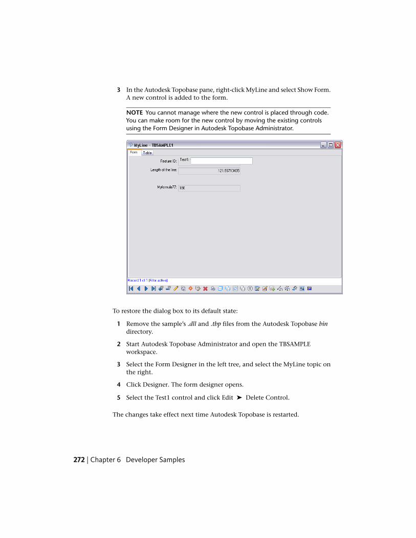
3 In the Autodesk Topobase pane, right-click MyLine and select Show Form.A new control is added to the form.
NOTE You cannot manage where the new control is placed through code.You can make room for the new control by moving the existing controlsusing the Form Designer in Autodesk Topobase Administrator.
To restore the dialog box to its default state:
1 Remove the sample’s .dll and .tbp files from the Autodesk Topobase bindirectory.
2 Start Autodesk Topobase Administrator and open the TBSAMPLEworkspace.
3 Select the Form Designer in the left tree, and select the MyLine topic onthe right.
4 Click Designer. The form designer opens.
5 Select the Test1 control and click Edit ➤ Delete Control.
The changes take effect next time Autodesk Topobase is restarted.
272 | Chapter 6 Developer Samples
Sample 83 - Remote Control
PurposeThis sample shows how to control Autodesk Topobase from another .Netapplication. It can be used in both the Autodesk Topobase Client (desktop)and Autodesk Topobase Web Client. This sample features the use of theTopobase.Forms.Remote.Client class.
ProcedureThis procedure assumes that you have added points to the TBSAMPLEworkspace by either using the Sample 02 - Read/Write Features (page 191)executable or digitizing point manually.
To use this sample:
1 Modify Form1.cs as follows:
■ In the ButtonOpenDialog_Click method, replace the first argumentto the OpenDialog call with “MYPOINT”.
■ In the ButtonHighlight_Click method, replace the argument to theAdd call with a FID value from the MYPOINT table. To determine aFID value, in an Oracle SQL*Plus session, do the following:connect tbsample/avs
select fid from mypoint;
2 Build the sample. The executable (VBSample83.exe or CSSample83.exe) iscopied to the Autodesk Topobase Client bin directory.
3 Ensure Autodesk Topobase is closed.
4 Run the program by either selecting Debug ➤ Start Debugging in VisualStudio or by directly running the samples .exe file in the AutodeskTopobase bin directory.
The sample’s main form is displayed.
Sample 83 - Remote Control | 273
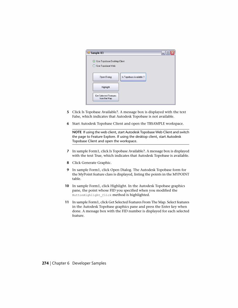
5 Click Is Topobase Available?. A message box is displayed with the textFalse, which indicates that Autodesk Topobase is not available.
6 Start Autodesk Topobase Client and open the TBSAMPLE workspace.
NOTE If using the web client, start Autodesk Topobase Web Client and switchthe page to Feature Explore. If using the desktop client, start AutodeskTopobase Client and open the workspace.
7 In sample Form1, click Is Topobase Available?. A message box is displayedwith the text True, which indicates that Autodesk Topobase is available.
8 Click Generate Graphic.
9 In sample Form1, click Open Dialog. The Autodesk Topobase form forthe MyPoint feature class is displayed, listing the points in the MYPOINTtable.
10 In sample Form1, click Highlight. In the Autodesk Topobase graphicspane, the point whose FID you specified when you modified theButtonHighlight_Click method is highlighted.
11 In sample Form1, click Get Selected Features From The Map. Select featuresin the Autodesk Topobase graphics pane and press the Enter key whendone. A message box with the FID number is displayed for each selectedfeature.
274 | Chapter 6 Developer Samples
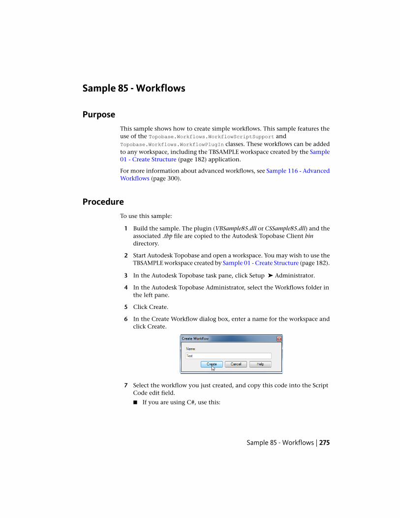
Sample 85 - Workflows
PurposeThis sample shows how to create simple workflows. This sample features theuse of the Topobase.Workflows.WorkflowScriptSupport andTopobase.Workflows.WorkflowPlugIn classes. These workflows can be addedto any workspace, including the TBSAMPLE workspace created by the Sample01 - Create Structure (page 182) application.
For more information about advanced workflows, see Sample 116 - AdvancedWorkflows (page 300).
ProcedureTo use this sample:
1 Build the sample. The plugin (VBSample85.dll or CSSample85.dll) and theassociated .tbp file are copied to the Autodesk Topobase Client bindirectory.
2 Start Autodesk Topobase and open a workspace. You may wish to use theTBSAMPLE workspace created by Sample 01 - Create Structure (page 182).
3 In the Autodesk Topobase task pane, click Setup ➤ Administrator.
4 In the Autodesk Topobase Administrator, select the Workflows folder inthe left pane.
5 Click Create.
6 In the Create Workflow dialog box, enter a name for the workspace andclick Create.
7 Select the workflow you just created, and copy this code into the ScriptCode edit field.
■ If you are using C#, use this:
Sample 85 - Workflows | 275
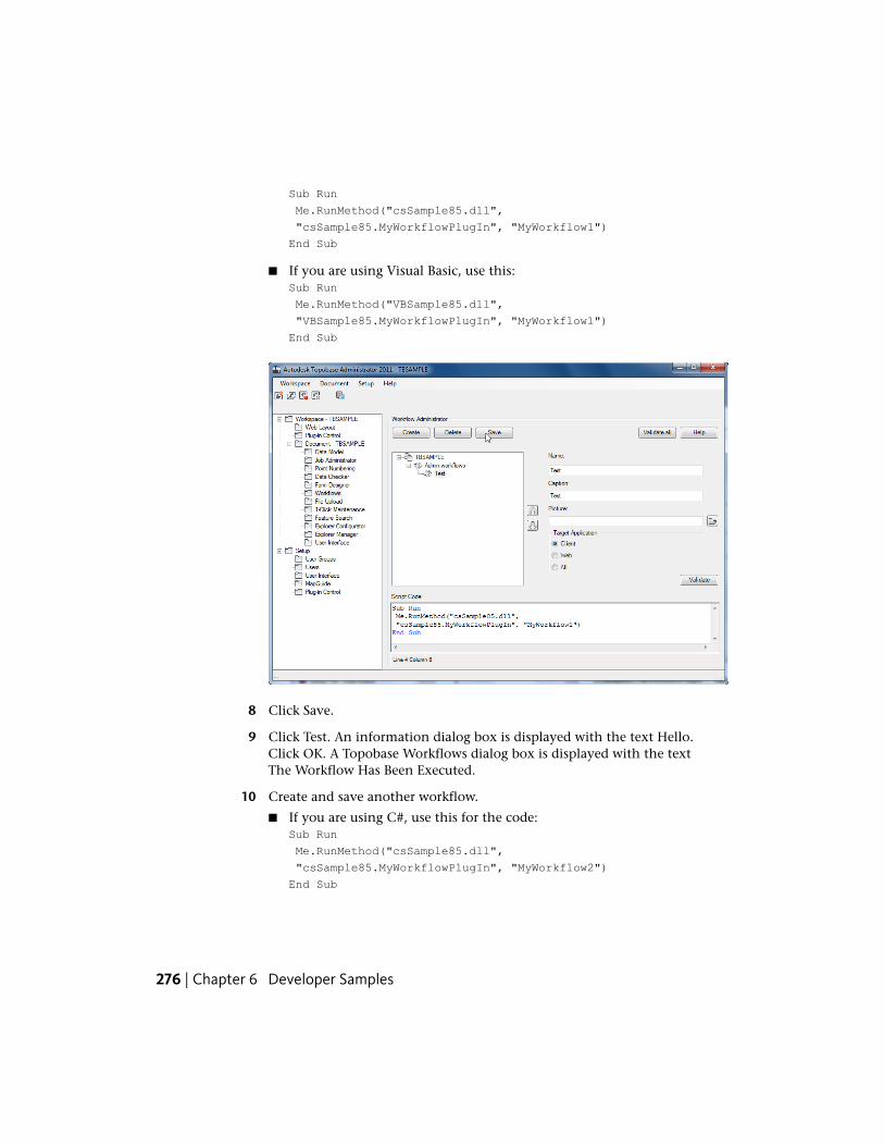
Sub Run
Me.RunMethod("csSample85.dll",
"csSample85.MyWorkflowPlugIn", "MyWorkflow1")
End Sub
■ If you are using Visual Basic, use this:Sub Run
Me.RunMethod("VBSample85.dll",
"VBSample85.MyWorkflowPlugIn", "MyWorkflow1")
End Sub
8 Click Save.
9 Click Test. An information dialog box is displayed with the text Hello.Click OK. A Topobase Workflows dialog box is displayed with the textThe Workflow Has Been Executed.
10 Create and save another workflow.
■ If you are using C#, use this for the code:Sub Run
Me.RunMethod("csSample85.dll",
"csSample85.MyWorkflowPlugIn", "MyWorkflow2")
End Sub
276 | Chapter 6 Developer Samples
■ If you are using Visual Basic, use this for the code:Sub Run
Me.RunMethod("VBSample85.dll",
"VBSample85.MyWorkflowPlugIn", "MyWorkflow2")
End Sub
11 (Re-)Start Autodesk Topobase and open the workspace
12 Click Generate Graphic.
13 In the Autodesk Topobase task pane, click the Workflow Explorer icon.The Workflow Explorer is displayed with three nodes representing thethree workflows added by Sample 85.
14 Start the first workflow by highlighting the node and pressing Executeor by selecting Execute from the context menu of the node. This samplesimply displays a message box and then ends.
15 Start the second workflow. The Workflow Explorer contents are replacedwith the text Please Digitize a Point.
16 Move the cursor into the graphics pane and click on a point. The PleaseDigitize a Point message is replaced with a Coordinates text box, whosecontent is the digitized point values. Click OK. The text box is replacedwith the contents of the Workflow Explorer.
Sample 86 - Update Plugin
PurposeThis sample shows how to update the data model of a workspace document.This sample uses the TBSAMPLE workspace created by the Sample 01 - CreateStructure (page 182) application.
ProcedureTo use this sample:
1 Build the sample. The plugin (VBSample86.dll or CSSample86.dll) and theassociated .tbp file are copied to the Autodesk Topobase Client bindirectory.
Sample 86 - Update Plugin | 277
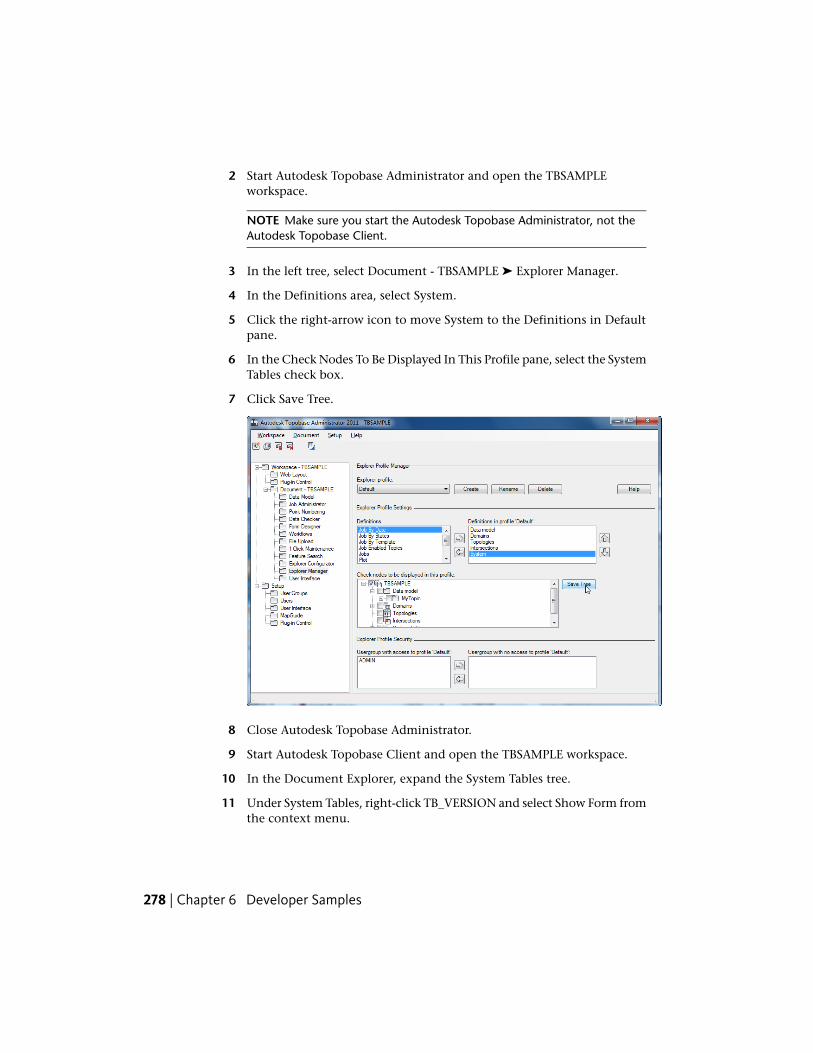
2 Start Autodesk Topobase Administrator and open the TBSAMPLEworkspace.
NOTE Make sure you start the Autodesk Topobase Administrator, not theAutodesk Topobase Client.
3 In the left tree, select Document - TBSAMPLE ➤ Explorer Manager.
4 In the Definitions area, select System.
5 Click the right-arrow icon to move System to the Definitions in Defaultpane.
6 In the Check Nodes To Be Displayed In This Profile pane, select the SystemTables check box.
7 Click Save Tree.
8 Close Autodesk Topobase Administrator.
9 Start Autodesk Topobase Client and open the TBSAMPLE workspace.
10 In the Document Explorer, expand the System Tables tree.
11 Under System Tables, right-click TB_VERSION and select Show Form fromthe context menu.
278 | Chapter 6 Developer Samples

12 Select the New Record toolbar button and create a new record withthese values:
■ Version = 0.0.0
■ Module Name = CHUCHUTRAIN
Set the Version_date to some date in the past.
13 Click Insert (F5).
14 Close the form. Close Autodesk Topobase Client.
15 Open Autodesk Topobase Administrator and re-open the TBSAMPLEworkspace.
Sample 86 - Update Plugin | 279
Sample 87 - Jobs
PurposeThis sample shows how to create a new job and how to change the state of ajob. This sample uses the TBSAMPLE workspace created by the Sample 01 -Create Structure (page 182) application.
ProcedureTo use this sample:
1 Build the sample. The plugin (VBSample87.dll or CSSample87.dll) and theassociated .tbp file are copied to the Autodesk Topobase Client bindirectory.
2 Start Autodesk Topobase Administrator and open the TBSAMPLEworkspace.
NOTE Make sure you start the Autodesk Topobase Administrator, not theAutodesk Topobase Client.
3 In the tree view on the left-hand side, select Data Model and then createa new feature class called MyFClassName.
4 Right-click MyTopic on the right and select Create FeatureClass.
280 | Chapter 6 Developer Samples
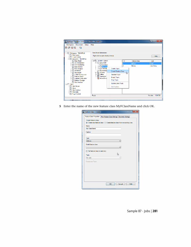
5 Enter the name of the new feature class MyFClassName and click OK.
Sample 87 - Jobs | 281
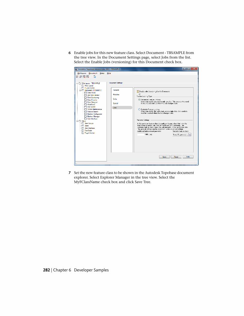
6 Enable jobs for this new feature class. Select Document - TBSAMPLE fromthe tree view. In the Document Settings page, select Jobs from the list.Select the Enable Jobs (versioning) for this Document check box.
7 Set the new feature class to be shown in the Autodesk Topobase documentexplorer. Select Explorer Manager in the tree view. Select theMyFClassName check box and click Save Tree.
282 | Chapter 6 Developer Samples
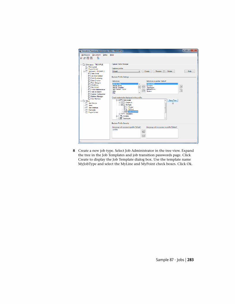
8 Create a new job type. Select Job Administrator in the tree view. Expandthe tree in the Job Templates and job transition passwords page. ClickCreate to display the Job Template dialog box. Use the template nameMyJobType and select the MyLine and MyPoint check boxes. Click Ok.
Sample 87 - Jobs | 283
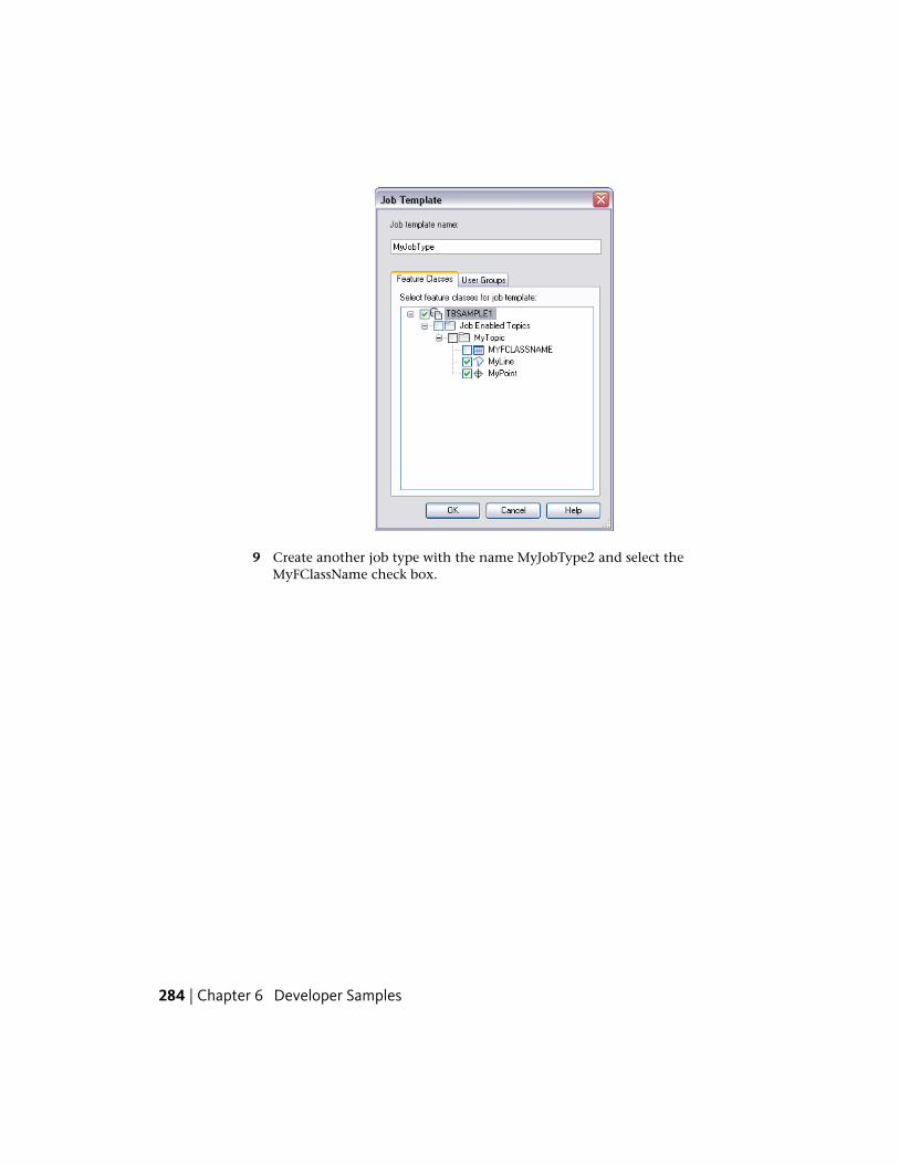
9 Create another job type with the name MyJobType2 and select theMyFClassName check box.
284 | Chapter 6 Developer Samples
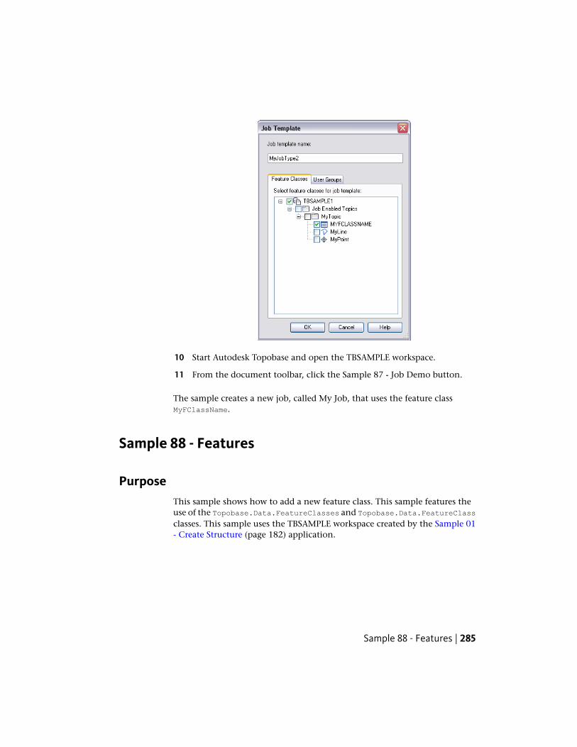
10 Start Autodesk Topobase and open the TBSAMPLE workspace.
11 From the document toolbar, click the Sample 87 - Job Demo button.
The sample creates a new job, called My Job, that uses the feature classMyFClassName.
Sample 88 - Features
PurposeThis sample shows how to add a new feature class. This sample features theuse of the Topobase.Data.FeatureClasses and Topobase.Data.FeatureClassclasses. This sample uses the TBSAMPLE workspace created by the Sample 01- Create Structure (page 182) application.
Sample 88 - Features | 285
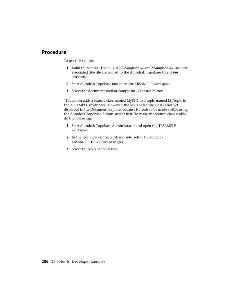
ProcedureTo use this sample:
1 Build the sample. The plugin (VBSample88.dll or CSSample88.dll) and theassociated .tbp file are copied to the Autodesk Topobase Client bindirectory.
2 Start Autodesk Topobase and open the TBSAMPLE workspace.
3 Select the document toolbar Sample 88 - Features button.
This action adds a feature class named MyFC2 to a topic named MyTopic inthe TBSAMPLE workspace. However, the MyFC2 feature class is not yetdisplayed in the Document Explorer because it needs to be made visible usingthe Autodesk Topobase Administrator first. To make the feature class visible,do the following:
1 Start Autodesk Topobase Administrator and open the TBSAMPLEworkspace.
2 In the tree view on the left-hand side, select Document -TBSAMPLE ➤ Explorer Manager.
3 Select the MyFC2 check box.
286 | Chapter 6 Developer Samples
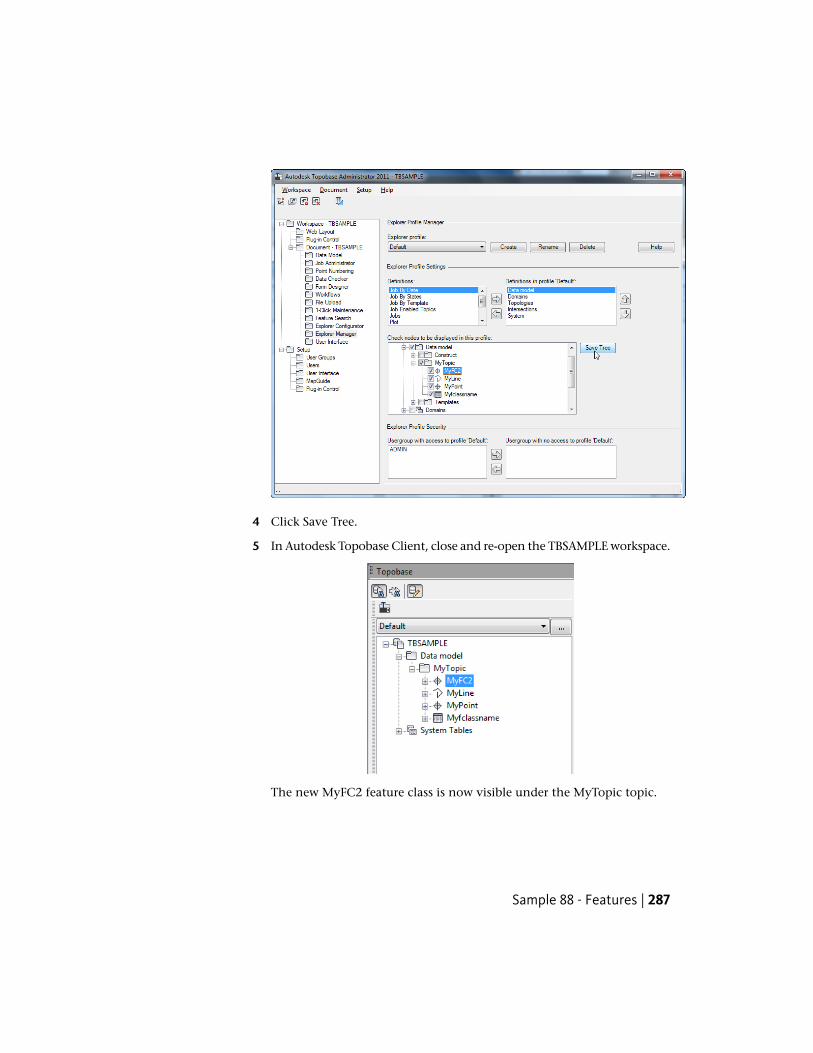
4 Click Save Tree.
5 In Autodesk Topobase Client, close and re-open the TBSAMPLE workspace.
The new MyFC2 feature class is now visible under the MyTopic topic.
Sample 88 - Features | 287
Sample 100 - Map Functions
PurposeThis sample shows how to interact with Autodesk Map 3D. This sample featuresthe use of the Topobase.Data.FeatureClass, Topobase.Data.FeatureList,and Topobase.Map.MapLogic classes. This sample uses the TBSAMPLE workspacecreated by the Sample 01 - Create Structure (page 182) application.
ProcedureTo use this sample:
1 Build the sample. The plugin (VBSample100.dll or CSSample100.dll) andthe associated .tbp file are copied to the Autodesk Topobase Client bindirectory.
2 Start Autodesk Topobase and open the TBSAMPLE workspace
3 Click Generate Graphic.
4 Record some of the FIDs in the MyPoint and MyLine tables. You can dothis by displaying the forms for the MyPoint and MyLine feature classes.Alternatively, in an Oracle SQL*Plus session, do the following:
connect tbsample/avs
select fid from mypoint;
select fid from myline;
5 Select the application toolbar Sample 100 - Map Function button. Thesample’s dialog box is displayed.
288 | Chapter 6 Developer Samples
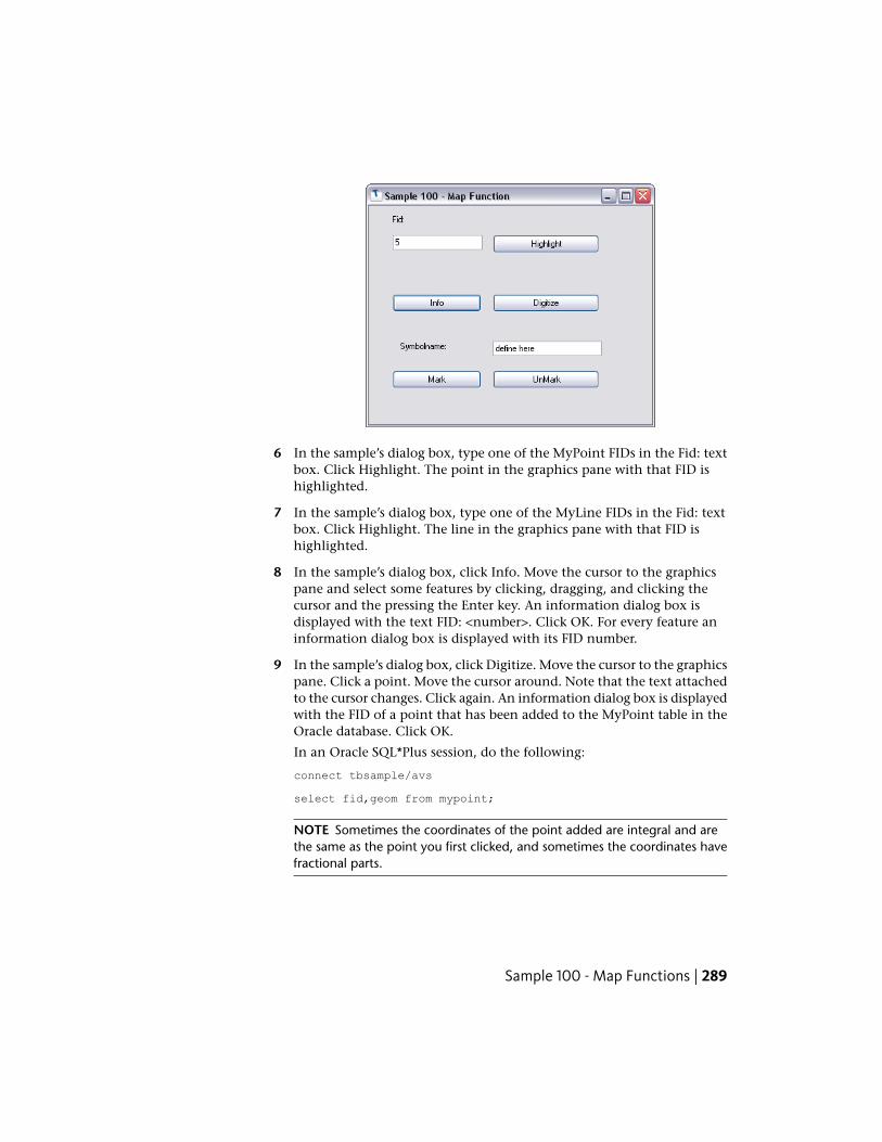
6 In the sample’s dialog box, type one of the MyPoint FIDs in the Fid: textbox. Click Highlight. The point in the graphics pane with that FID ishighlighted.
7 In the sample’s dialog box, type one of the MyLine FIDs in the Fid: textbox. Click Highlight. The line in the graphics pane with that FID ishighlighted.
8 In the sample’s dialog box, click Info. Move the cursor to the graphicspane and select some features by clicking, dragging, and clicking thecursor and the pressing the Enter key. An information dialog box isdisplayed with the text FID: <number>. Click OK. For every feature aninformation dialog box is displayed with its FID number.
9 In the sample’s dialog box, click Digitize. Move the cursor to the graphicspane. Click a point. Move the cursor around. Note that the text attachedto the cursor changes. Click again. An information dialog box is displayedwith the FID of a point that has been added to the MyPoint table in theOracle database. Click OK.
In an Oracle SQL*Plus session, do the following:
connect tbsample/avs
select fid,geom from mypoint;
NOTE Sometimes the coordinates of the point added are integral and arethe same as the point you first clicked, and sometimes the coordinates havefractional parts.
Sample 100 - Map Functions | 289
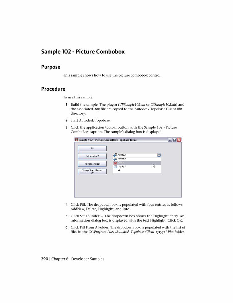
Sample 102 - Picture Combobox
PurposeThis sample shows how to use the picture combobox control.
ProcedureTo use this sample:
1 Build the sample. The plugin (VBSample102.dll or CSSample102.dll) andthe associated .tbp file are copied to the Autodesk Topobase Client bindirectory.
2 Start Autodesk Topobase.
3 Click the application toolbar button with the Sample 102 - PictureComboBox caption. The sample’s dialog box is displayed.
4 Click Fill. The dropdown box is populated with four entries as follows:AddNew, Delete, Highlight, and Info.
5 Click Set To Index 2. The dropdown box shows the Highlight entry. Aninformation dialog box is displayed with the text Highlight. Click OK.
6 Click Fill From A Folder. The dropdown box is populated with the list offiles in the C:\Program Files\Autodesk Topobase Client <yyyy>\Pics folder.
290 | Chapter 6 Developer Samples
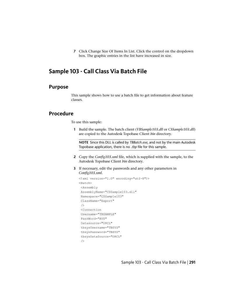
7 Click Change Size Of Items In List. Click the control on the dropdownbox. The graphic entries in the list have increased in size.
Sample 103 - Call Class Via Batch File
PurposeThis sample shows how to use a batch file to get information about featureclasses.
ProcedureTo use this sample:
1 Build the sample. The batch client (VBSample103.dll or CSSample103.dll)are copied to the Autodesk Topobase Client bin directory.
NOTE Since this DLL is called by TBBatch.exe, and not by the main AutodeskTopobase application, there is no .tbp file for this sample.
2 Copy the Config103.xml file, which is supplied with the sample, to theAutodesk Topobase Client bin directory.
3 If necessary, edit the passwords and any other parameters inConfig103.xml.
<?xml version="1.0" encoding="utf-8"?>
<Batch>
<Assembly
AssemblyName="CSSample103.dll"
Namespace="CSSample103"
ClassName="Export"
/>
<Connection
Username="TBSAMPLE"
PassWord="AVS"
Datasource="ORCL"
tbsysUsername="TBSYS"
tbsysPassword="TBSYS"
tbsysDataSource="ORCL"
/>
Sample 103 - Call Class Via Batch File | 291
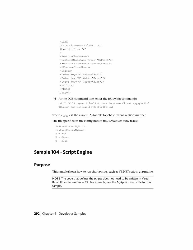
<Data
OutputFilename="C:\Test.txt"
SeparatorSign=";"
>
<FeatureClassNames>
<FeatureClassName Value="MyPoint"/>
<FeatureClassName Value="MyLine"/>
</FeatureClassNames>
<Colors>
<Color Key="A" Value="Red"/>
<Color Key="B" Value="Green"/>
<Color Key="C" Value="Blue"/>
</Colors>
</Data>
</Batch>
4 At the DOS command line, enter the following commands:
cd /d "C:\Program Files\Autodesk Topobase Client <yyyy>\Bin"
TBBatch.exe ConfigFile=Config103.xml
where <yyyy> is the current Autodesk Topobase Client version number.
The file specified in the configuration file, C:\test.txt, now reads:
FeatureClass:MyPoint
FeatureClass:MyLine
A - Red
B - Green
C - Blue
Sample 104 - Script Engine
PurposeThis sample shows how to run short scripts, such as VB.NET scripts, at runtime.
NOTE The code that defines the scripts does not need to be written in VisualBasic. It can be written in C#. For example, see the MyApplication.cs file for thissample.
292 | Chapter 6 Developer Samples
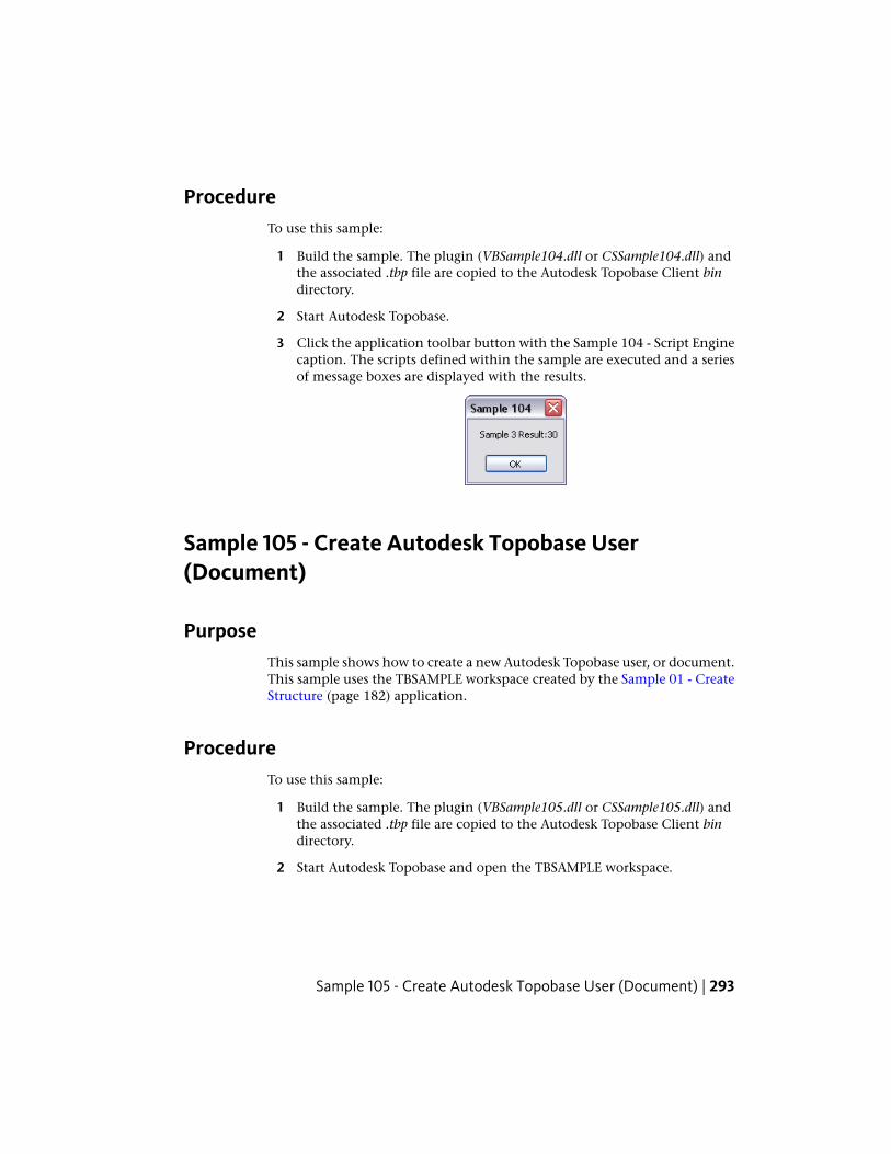
ProcedureTo use this sample:
1 Build the sample. The plugin (VBSample104.dll or CSSample104.dll) andthe associated .tbp file are copied to the Autodesk Topobase Client bindirectory.
2 Start Autodesk Topobase.
3 Click the application toolbar button with the Sample 104 - Script Enginecaption. The scripts defined within the sample are executed and a seriesof message boxes are displayed with the results.
Sample 105 - Create Autodesk Topobase User(Document)
PurposeThis sample shows how to create a new Autodesk Topobase user, or document.This sample uses the TBSAMPLE workspace created by the Sample 01 - CreateStructure (page 182) application.
ProcedureTo use this sample:
1 Build the sample. The plugin (VBSample105.dll or CSSample105.dll) andthe associated .tbp file are copied to the Autodesk Topobase Client bindirectory.
2 Start Autodesk Topobase and open the TBSAMPLE workspace.
Sample 105 - Create Autodesk Topobase User (Document) | 293
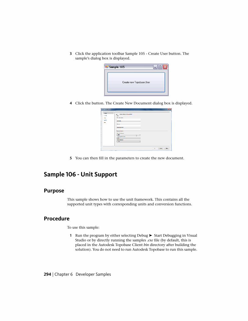
3 Click the application toolbar Sample 105 - Create User button. Thesample’s dialog box is displayed.
4 Click the button. The Create New Document dialog box is displayed.
5 You can then fill in the parameters to create the new document.
Sample 106 - Unit Support
PurposeThis sample shows how to use the unit framework. This contains all thesupported unit types with corresponding units and conversion functions.
ProcedureTo use this sample:
1 Run the program by either selecting Debug ➤ Start Debugging in VisualStudio or by directly running the samples .exe file (by default, this isplaced in the Autodesk Topobase Client bin directory after building thesolution). You do not need to run Autodesk Topobase to run this sample.
294 | Chapter 6 Developer Samples
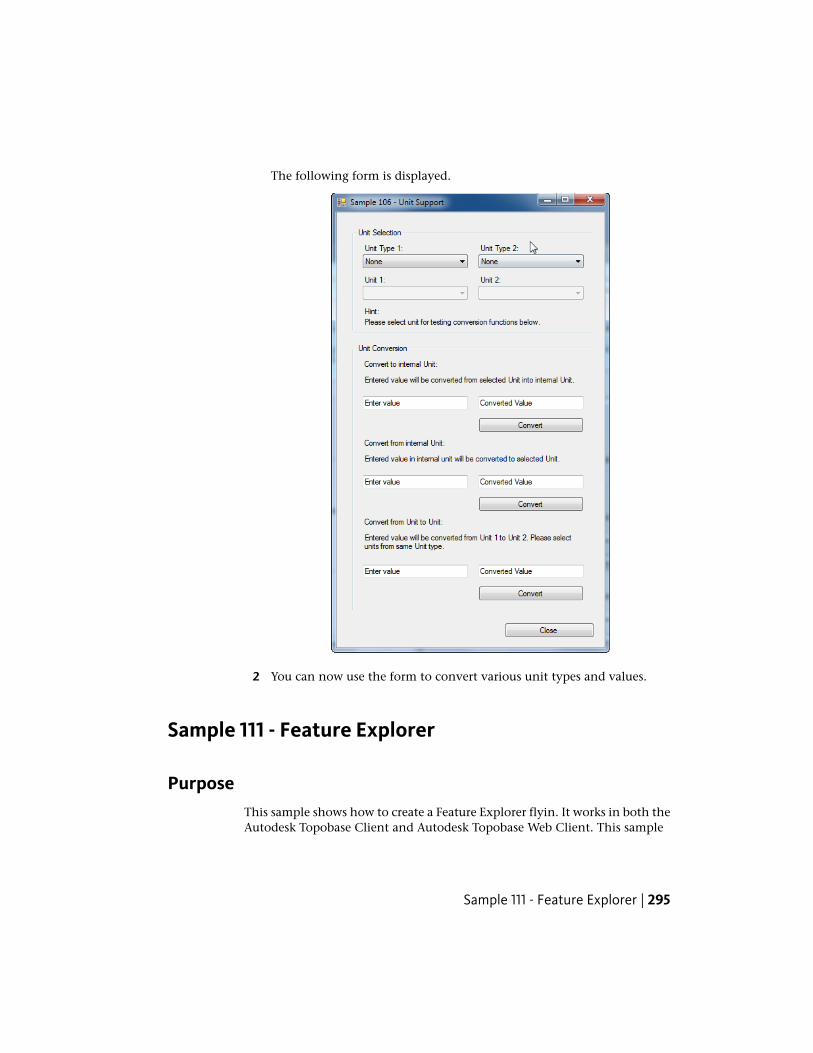
The following form is displayed.
2 You can now use the form to convert various unit types and values.
Sample 111 - Feature Explorer
PurposeThis sample shows how to create a Feature Explorer flyin. It works in both theAutodesk Topobase Client and Autodesk Topobase Web Client. This sample
Sample 111 - Feature Explorer | 295
uses the TBSAMPLE workspace created by the Sample 01 - Create Structure(page 182) application. It features the use of the following classes:
■ Topobase.Forms.Desktop.DocumentFlyIn
■ Topobase.Forms.UserControls.FeatureExplorer.FeatureExplorerData
■ Topobase.Forms.UserControls.FeatureExplorer.AbstractDesktopFeatureExplorerController
■ Topobase.Forms.UserControls.FeatureExplorer.Action
■ Topobase.Forms.UserControls.FeatureExplorer.Category
■ Topobase.Data.FeatureClass
■ Topobase.Data.Feature
■ Topobase.Graphic.LineString
ProcedureTo use this sample:
1 Build the sample. The plugin (VBSample111.dll or CSSample111.dll) andthe associated .tbp file are copied to the Autodesk Topobase Client bindirectory.
2 Start Autodesk Topobase and open the TBSAMPLE workspace. The maintoolbar of the Autodesk Topobase task pane has an additional Sample111 - Feature Explorer button next to the buttons for the DocumentExplorer and Workflow Explorer.
3 Click Generate Graphic.
4 Click the explorer toolbar Sample 111 - Feature Explorer button. Thisdisplays the Feature Explorer flyin at the bottom of the Autodesk Topobasetask pane.
296 | Chapter 6 Developer Samples
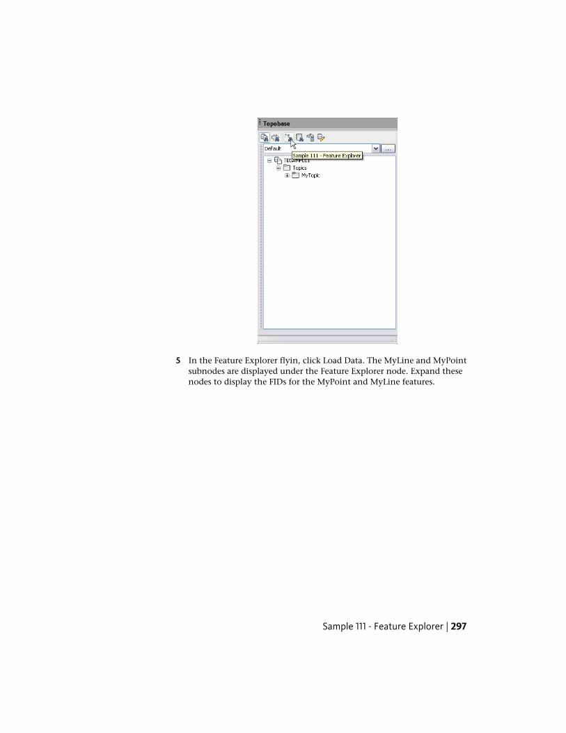
5 In the Feature Explorer flyin, click Load Data. The MyLine and MyPointsubnodes are displayed under the Feature Explorer node. Expand thesenodes to display the FIDs for the MyPoint and MyLine features.
Sample 111 - Feature Explorer | 297
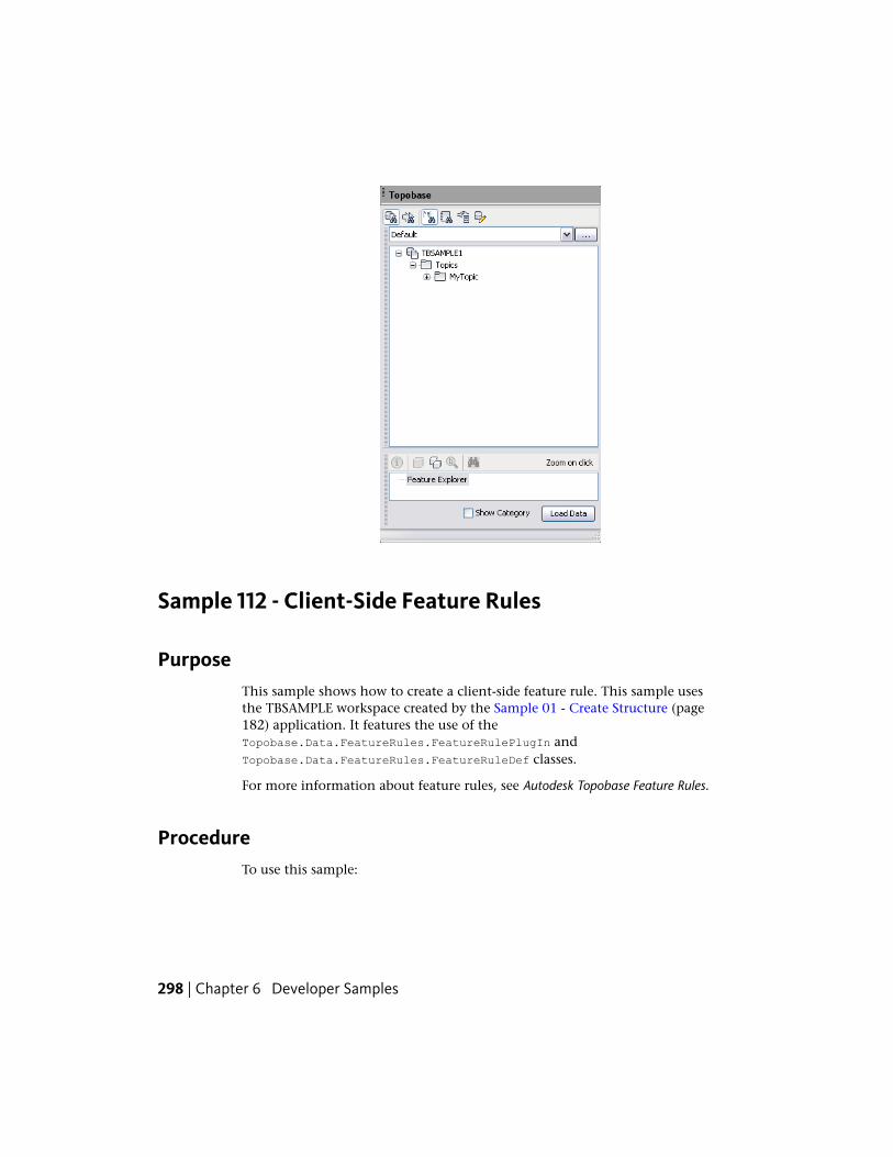
Sample 112 - Client-Side Feature Rules
PurposeThis sample shows how to create a client-side feature rule. This sample usesthe TBSAMPLE workspace created by the Sample 01 - Create Structure (page182) application. It features the use of theTopobase.Data.FeatureRules.FeatureRulePlugIn andTopobase.Data.FeatureRules.FeatureRuleDef classes.
For more information about feature rules, see Autodesk Topobase Feature Rules.
ProcedureTo use this sample:
298 | Chapter 6 Developer Samples
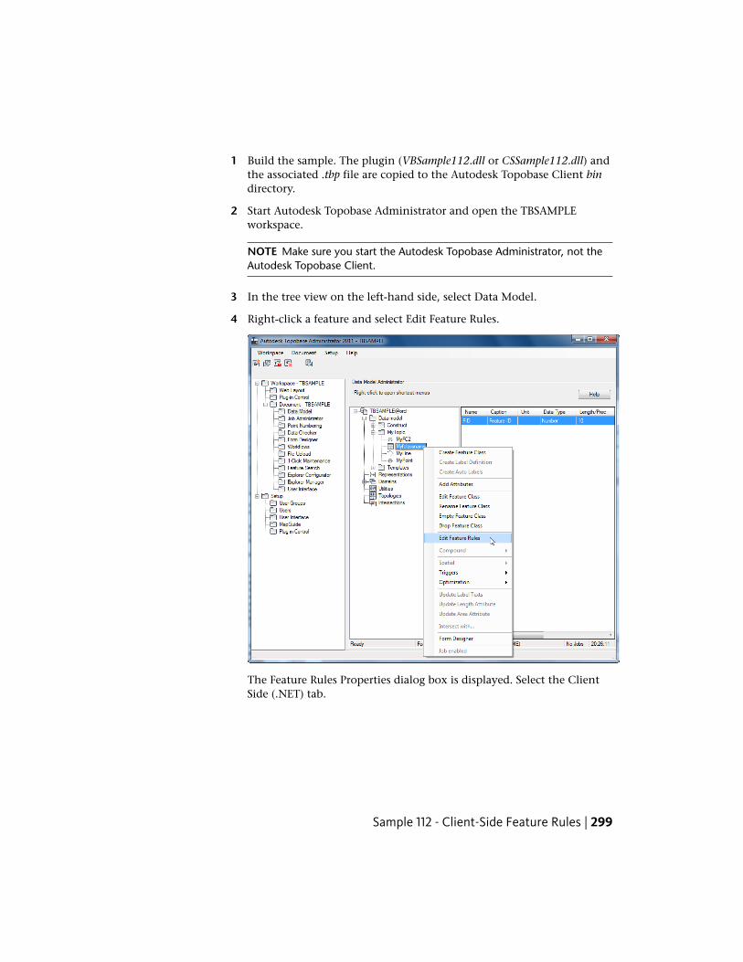
1 Build the sample. The plugin (VBSample112.dll or CSSample112.dll) andthe associated .tbp file are copied to the Autodesk Topobase Client bindirectory.
2 Start Autodesk Topobase Administrator and open the TBSAMPLEworkspace.
NOTE Make sure you start the Autodesk Topobase Administrator, not theAutodesk Topobase Client.
3 In the tree view on the left-hand side, select Data Model.
4 Right-click a feature and select Edit Feature Rules.
The Feature Rules Properties dialog box is displayed. Select the ClientSide (.NET) tab.
Sample 112 - Client-Side Feature Rules | 299
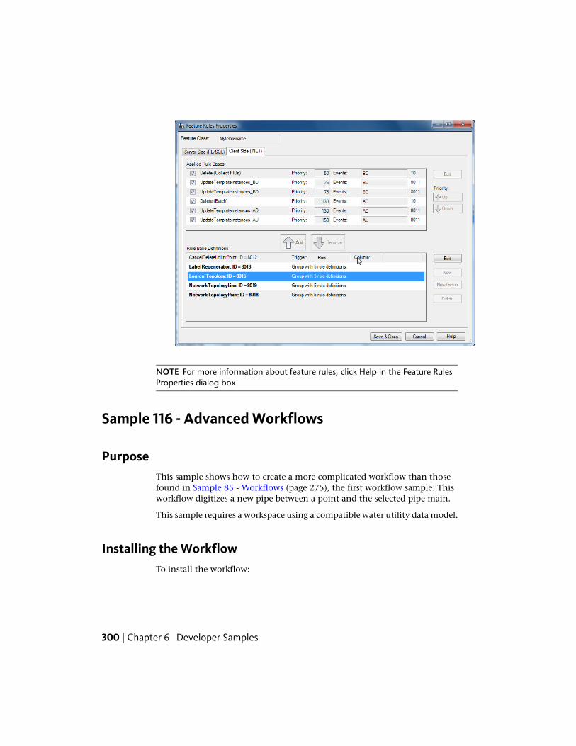
NOTE For more information about feature rules, click Help in the Feature RulesProperties dialog box.
Sample 116 - Advanced Workflows
PurposeThis sample shows how to create a more complicated workflow than thosefound in Sample 85 - Workflows (page 275), the first workflow sample. Thisworkflow digitizes a new pipe between a point and the selected pipe main.
This sample requires a workspace using a compatible water utility data model.
Installing the WorkflowTo install the workflow:
300 | Chapter 6 Developer Samples
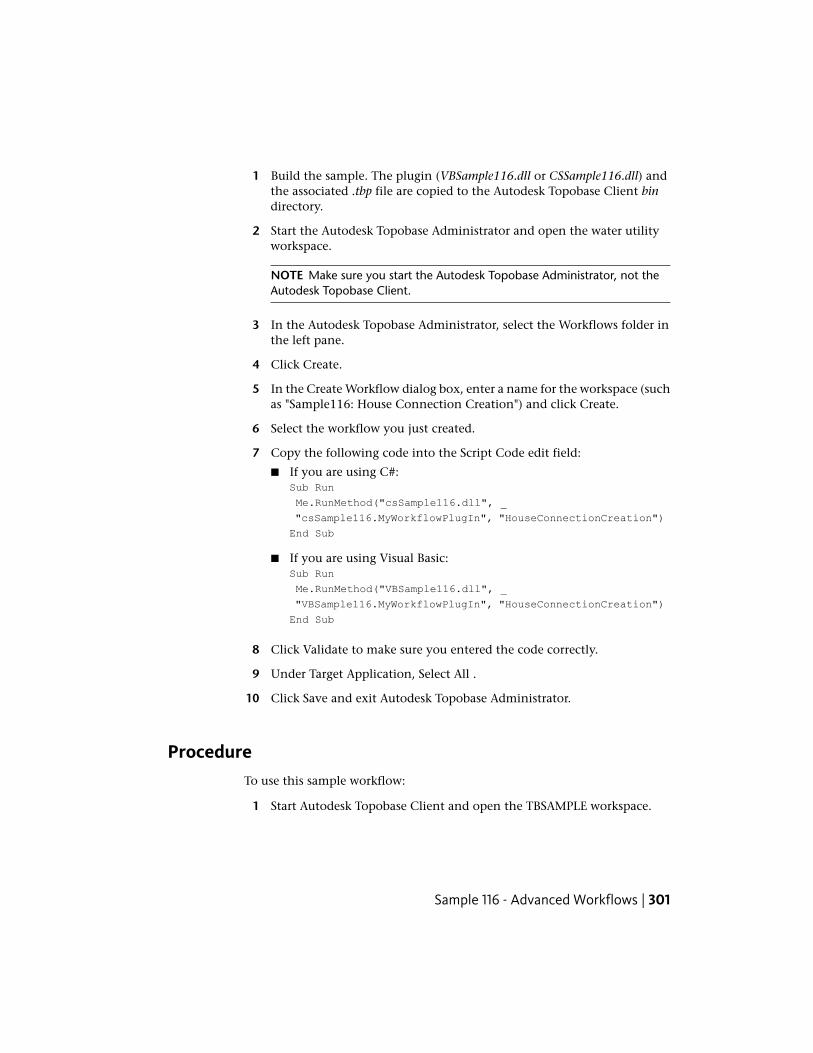
1 Build the sample. The plugin (VBSample116.dll or CSSample116.dll) andthe associated .tbp file are copied to the Autodesk Topobase Client bindirectory.
2 Start the Autodesk Topobase Administrator and open the water utilityworkspace.
NOTE Make sure you start the Autodesk Topobase Administrator, not theAutodesk Topobase Client.
3 In the Autodesk Topobase Administrator, select the Workflows folder inthe left pane.
4 Click Create.
5 In the Create Workflow dialog box, enter a name for the workspace (suchas "Sample116: House Connection Creation") and click Create.
6 Select the workflow you just created.
7 Copy the following code into the Script Code edit field:
■ If you are using C#:Sub Run
Me.RunMethod("csSample116.dll", _
"csSample116.MyWorkflowPlugIn", "HouseConnectionCreation")
End Sub
■ If you are using Visual Basic:Sub Run
Me.RunMethod("VBSample116.dll", _
"VBSample116.MyWorkflowPlugIn", "HouseConnectionCreation")
End Sub
8 Click Validate to make sure you entered the code correctly.
9 Under Target Application, Select All .
10 Click Save and exit Autodesk Topobase Administrator.
ProcedureTo use this sample workflow:
1 Start Autodesk Topobase Client and open the TBSAMPLE workspace.
Sample 116 - Advanced Workflows | 301
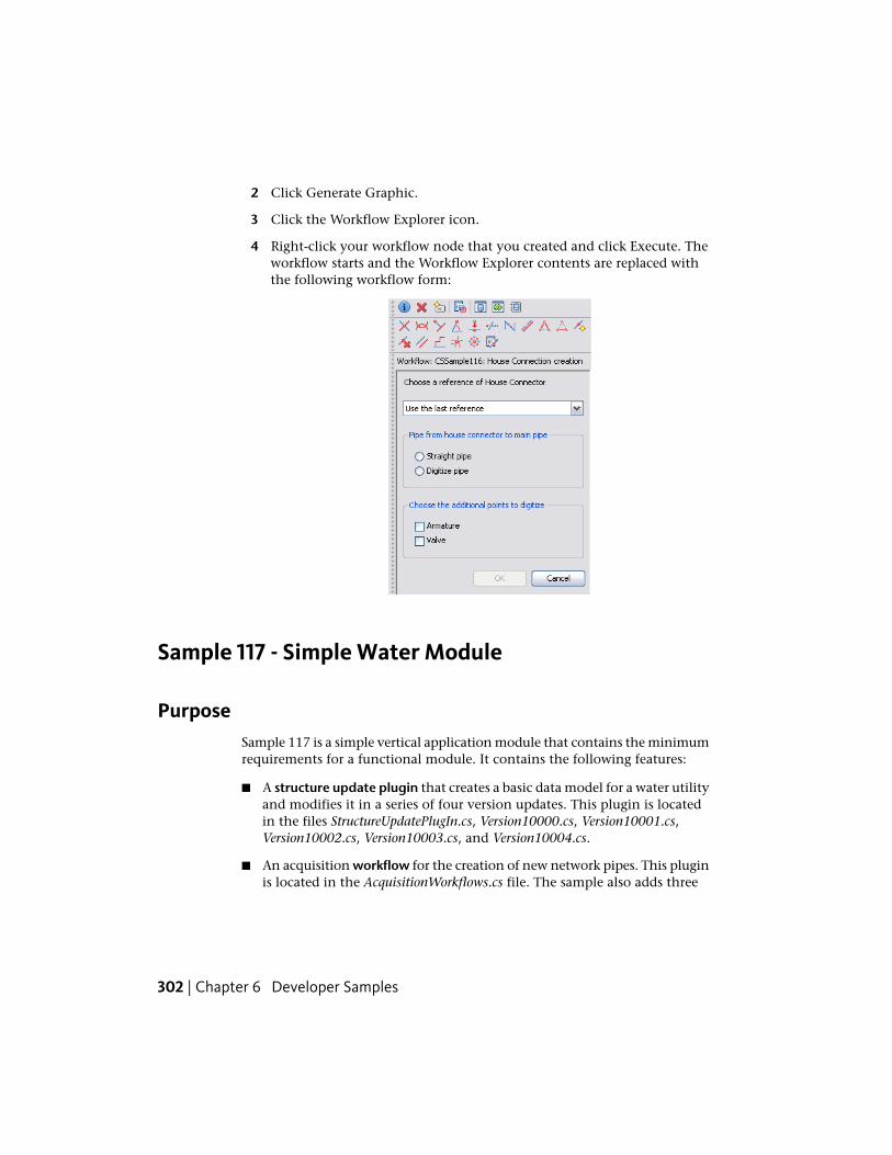
2 Click Generate Graphic.
3 Click the Workflow Explorer icon.
4 Right-click your workflow node that you created and click Execute. Theworkflow starts and the Workflow Explorer contents are replaced withthe following workflow form:
Sample 117 - Simple Water Module
PurposeSample 117 is a simple vertical application module that contains the minimumrequirements for a functional module. It contains the following features:
■ A structure update plugin that creates a basic data model for a water utilityand modifies it in a series of four version updates. This plugin is locatedin the files StructureUpdatePlugIn.cs, Version10000.cs, Version10001.cs,Version10002.cs, Version10003.cs, and Version10004.cs.
■ An acquisition workflow for the creation of new network pipes. This pluginis located in the AcquisitionWorkflows.cs file. The sample also adds three
302 | Chapter 6 Developer Samples
categories of workflows using the AddOrUpdateWorkflow API method duringthe version update in the Version10003.cs file.
■ A feature rules plugin enforcing the module’s business rules - in this case,filling in attributes whenever a feature is created or modified. This pluginis located in the FeatureRules.cs file.
■ A document plugin that creates a new menu item that links to the pipecreation workflow. This plugin is located in the DocumentPlugIn.cs file.
For more information about defining and manipulating the data model anda more complete description of vertical application modules, see CreatingApplication Modules (page 87).
Procedure
Building and Installing
Build the sample project. The library (VBSample117.dll or CSSample117.dll) isautomatically copied to the Autodesk Topobase Client bin directory. Thislibrary and the associated .tbp file need to be manually copied into theAutodesk Topobase Administrator bin directory as well.
Creating a Document Using the Module
1 Launch the Autodesk Topobase Administrator application.
2 Load an existing workspace or create a new workspace (see Create aWorkspace (page 185) for more information).
3 Select the New button in the Document box to create a new document.
Sample 117 - Simple Water Module | 303
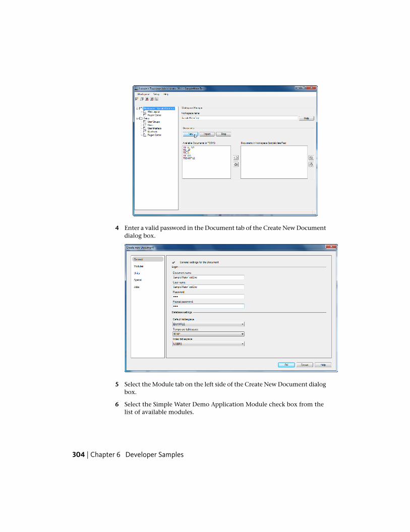
4 Enter a valid password in the Document tab of the Create New Documentdialog box.
5 Select the Module tab on the left side of the Create New Document dialogbox.
6 Select the Simple Water Demo Application Module check box from thelist of available modules.
304 | Chapter 6 Developer Samples
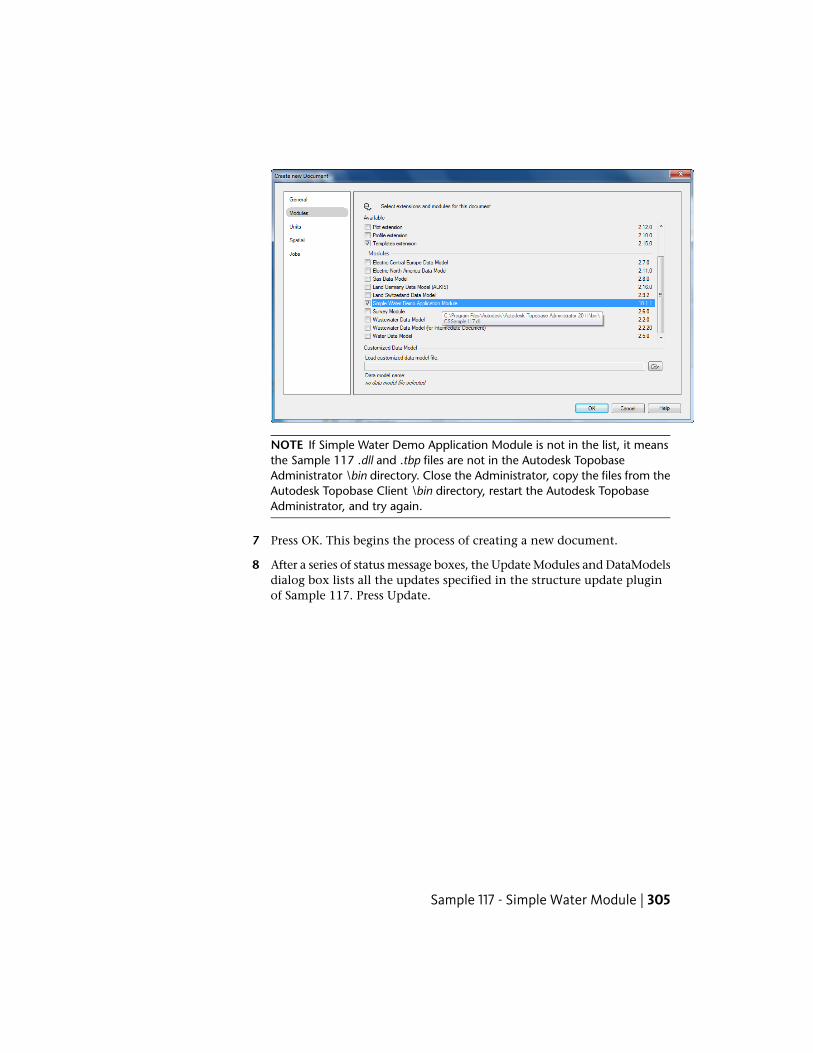
NOTE If Simple Water Demo Application Module is not in the list, it meansthe Sample 117 .dll and .tbp files are not in the Autodesk TopobaseAdministrator \bin directory. Close the Administrator, copy the files from theAutodesk Topobase Client \bin directory, restart the Autodesk TopobaseAdministrator, and try again.
7 Press OK. This begins the process of creating a new document.
8 After a series of status message boxes, the Update Modules and DataModelsdialog box lists all the updates specified in the structure update pluginof Sample 117. Press Update.
Sample 117 - Simple Water Module | 305
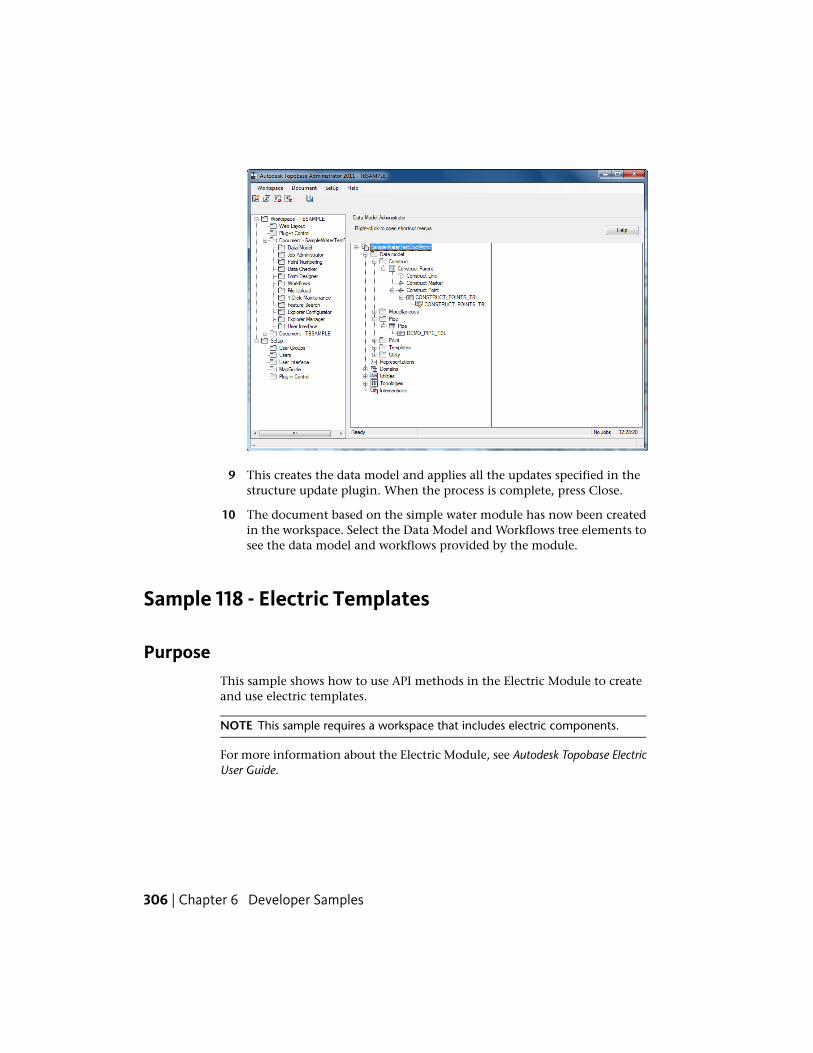
9 This creates the data model and applies all the updates specified in thestructure update plugin. When the process is complete, press Close.
10 The document based on the simple water module has now been createdin the workspace. Select the Data Model and Workflows tree elements tosee the data model and workflows provided by the module.
Sample 118 - Electric Templates
PurposeThis sample shows how to use API methods in the Electric Module to createand use electric templates.
NOTE This sample requires a workspace that includes electric components.
For more information about the Electric Module, see Autodesk Topobase ElectricUser Guide.
306 | Chapter 6 Developer Samples
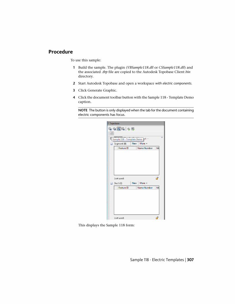
ProcedureTo use this sample:
1 Build the sample. The plugin (VBSample118.dll or CSSample118.dll) andthe associated .tbp file are copied to the Autodesk Topobase Client bindirectory.
2 Start Autodesk Topobase and open a workspace with electric components.
3 Click Generate Graphic.
4 Click the document toolbar button with the Sample 118 - Template Democaption.
NOTE The button is only displayed when the tab for the document containingelectric components has focus.
This displays the Sample 118 form:
Sample 118 - Electric Templates | 307
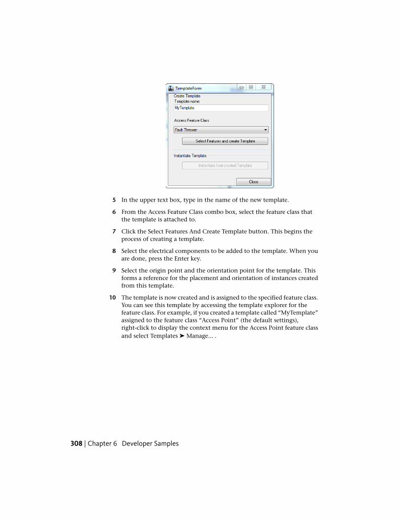
5 In the upper text box, type in the name of the new template.
6 From the Access Feature Class combo box, select the feature class thatthe template is attached to.
7 Click the Select Features And Create Template button. This begins theprocess of creating a template.
8 Select the electrical components to be added to the template. When youare done, press the Enter key.
9 Select the origin point and the orientation point for the template. Thisforms a reference for the placement and orientation of instances createdfrom this template.
10 The template is now created and is assigned to the specified feature class.You can see this template by accessing the template explorer for thefeature class. For example, if you created a template called “MyTemplate”assigned to the feature class “Access Point” (the default settings),right-click to display the context menu for the Access Point feature classand select Templates ➤ Manage... .
308 | Chapter 6 Developer Samples
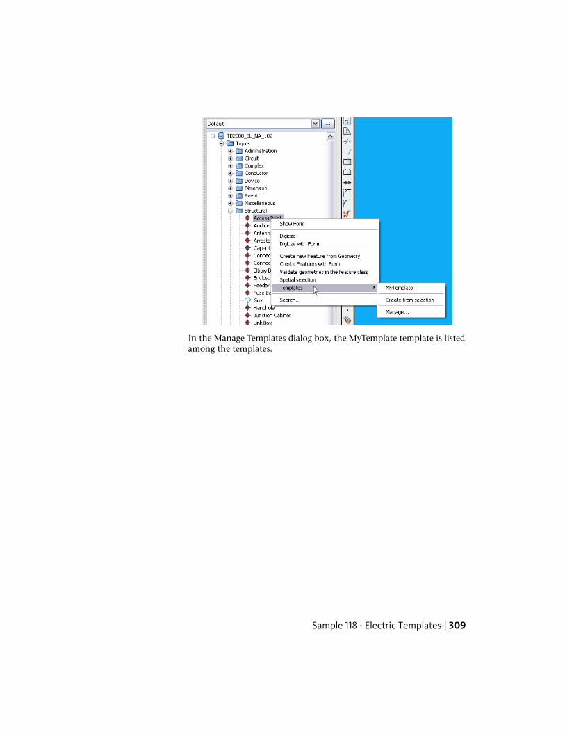
In the Manage Templates dialog box, the MyTemplate template is listedamong the templates.
Sample 118 - Electric Templates | 309
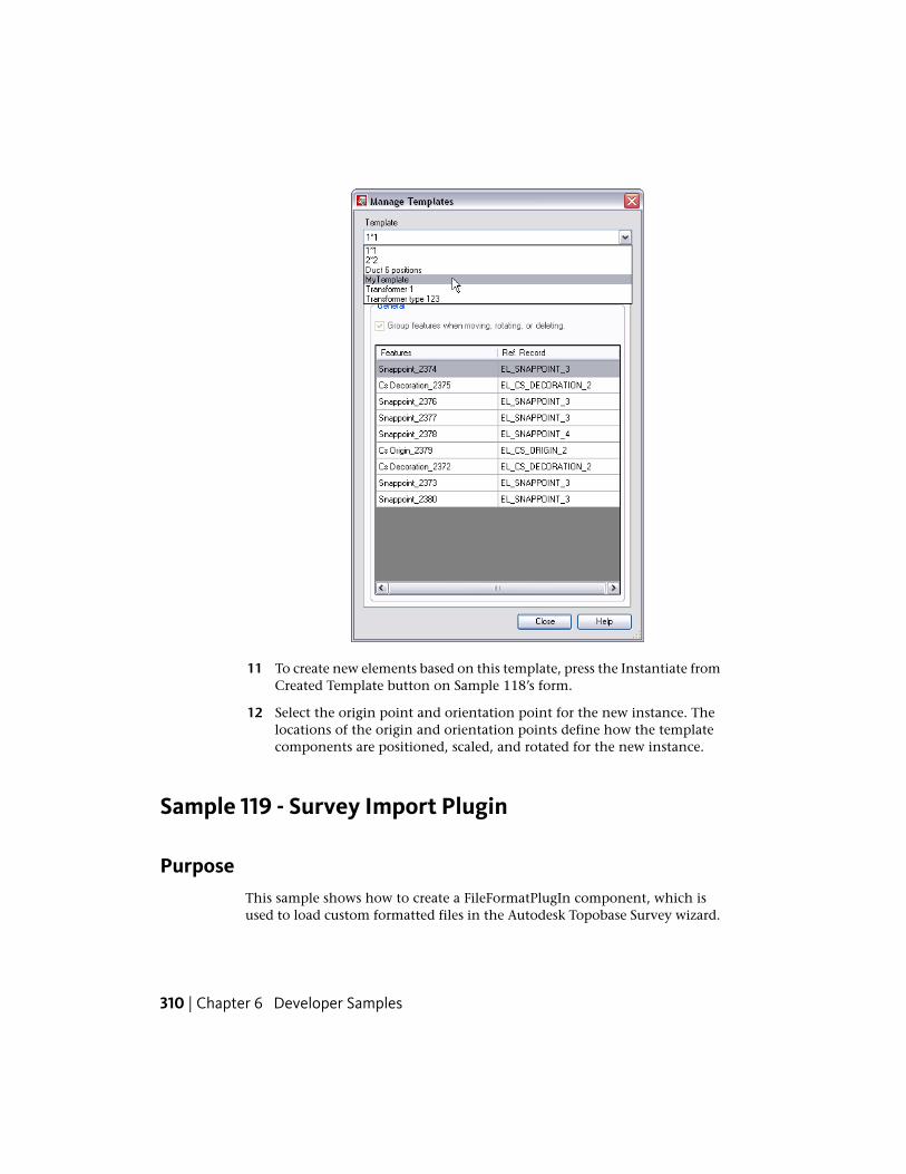
11 To create new elements based on this template, press the Instantiate fromCreated Template button on Sample 118’s form.
12 Select the origin point and orientation point for the new instance. Thelocations of the origin and orientation points define how the templatecomponents are positioned, scaled, and rotated for the new instance.
Sample 119 - Survey Import Plugin
PurposeThis sample shows how to create a FileFormatPlugIn component, which isused to load custom formatted files in the Autodesk Topobase Survey wizard.
310 | Chapter 6 Developer Samples
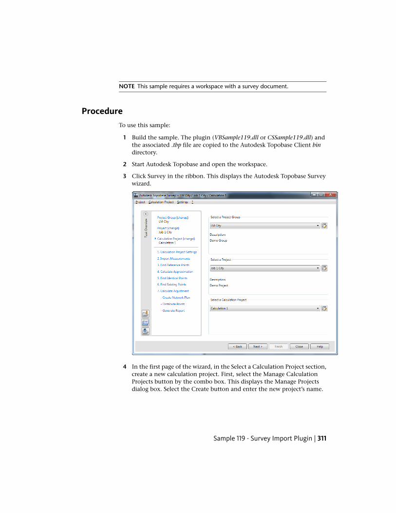
NOTE This sample requires a workspace with a survey document.
ProcedureTo use this sample:
1 Build the sample. The plugin (VBSample119.dll or CSSample119.dll) andthe associated .tbp file are copied to the Autodesk Topobase Client bindirectory.
2 Start Autodesk Topobase and open the workspace.
3 Click Survey in the ribbon. This displays the Autodesk Topobase Surveywizard.
4 In the first page of the wizard, in the Select a Calculation Project section,create a new calculation project. First, select the Manage CalculationProjects button by the combo box. This displays the Manage Projectsdialog box. Select the Create button and enter the new project’s name.
Sample 119 - Survey Import Plugin | 311
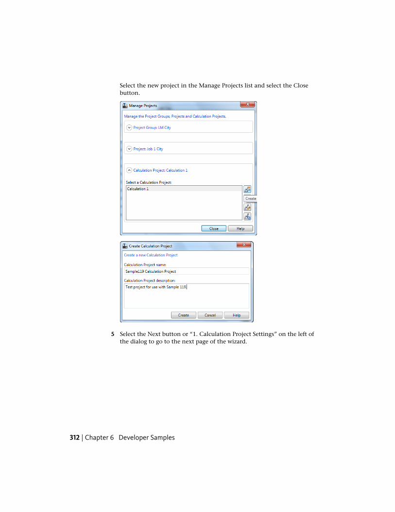
Select the new project in the Manage Projects list and select the Closebutton.
5 Select the Next button or “1. Calculation Project Settings” on the left ofthe dialog to go to the next page of the wizard.
312 | Chapter 6 Developer Samples
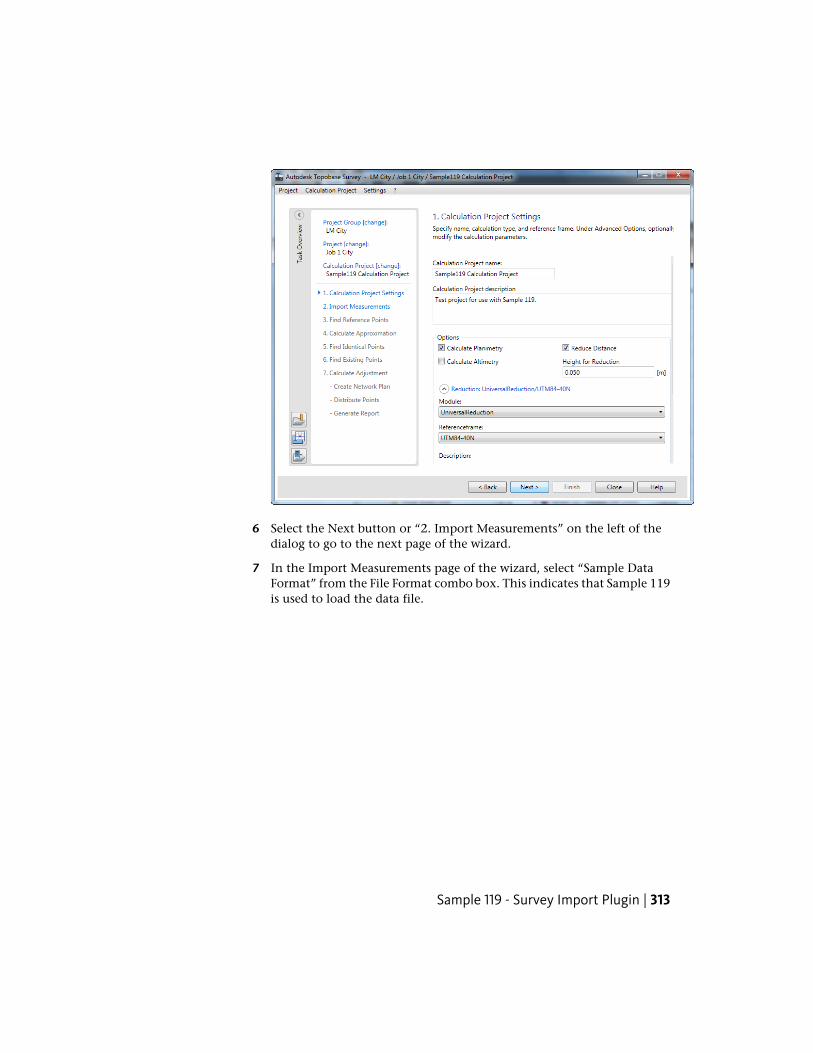
6 Select the Next button or “2. Import Measurements” on the left of thedialog to go to the next page of the wizard.
7 In the Import Measurements page of the wizard, select “Sample DataFormat” from the File Format combo box. This indicates that Sample 119is used to load the data file.
Sample 119 - Survey Import Plugin | 313
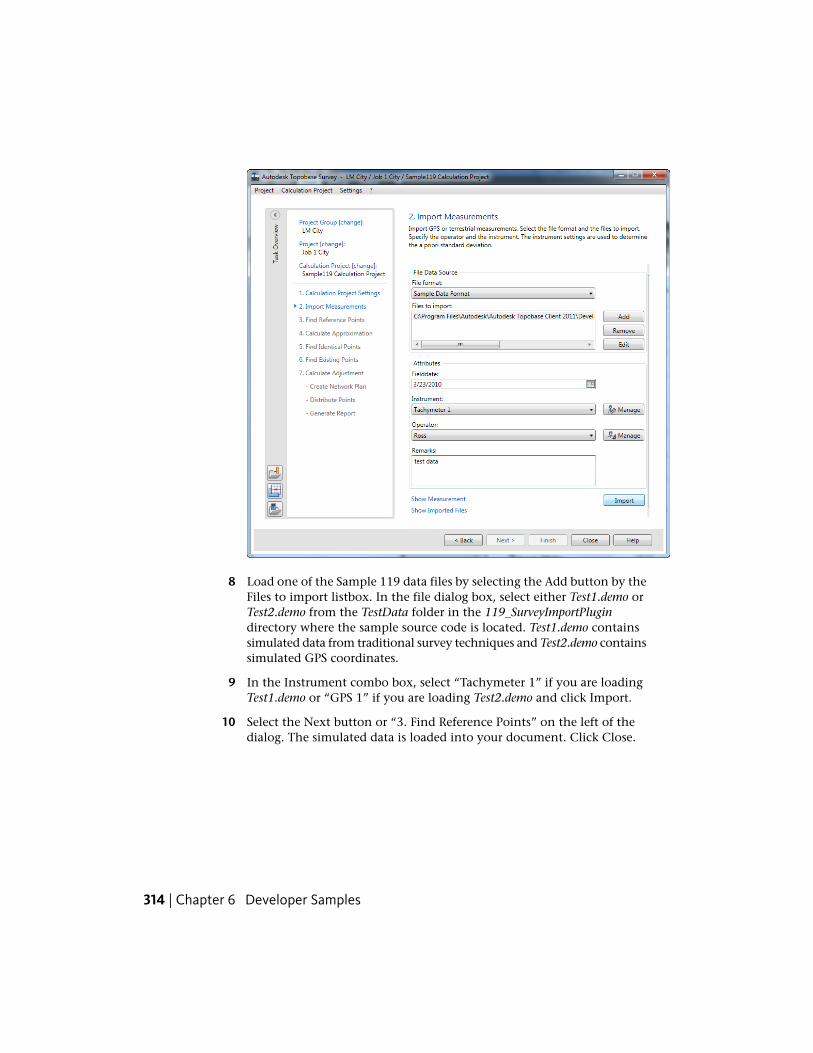
8 Load one of the Sample 119 data files by selecting the Add button by theFiles to import listbox. In the file dialog box, select either Test1.demo orTest2.demo from the TestData folder in the 119_SurveyImportPlugindirectory where the sample source code is located. Test1.demo containssimulated data from traditional survey techniques and Test2.demo containssimulated GPS coordinates.
9 In the Instrument combo box, select “Tachymeter 1” if you are loadingTest1.demo or “GPS 1” if you are loading Test2.demo and click Import.
10 Select the Next button or “3. Find Reference Points” on the left of thedialog. The simulated data is loaded into your document. Click Close.
314 | Chapter 6 Developer Samples
Sample 120 - Custom URL Invoking
PurposeThis sample shows how to use an ApplicationPlugin to create a new commandthat can be run using URL invoking.
ProcedureTo use this sample:
1 Build the sample. The plugin (VBSample120.dll or CSSample120.dll) andthe associated .tbp file are copied to the Autodesk Topobase Client bindirectory.
2 Start Autodesk Topobase and open a workspace.
3 Click Generate Graphic.
Sample 121 - Web Service
PurposeThis sample contains both a web service that communicates with a localinstallation of Autodesk Topobase and a web client that allows remote usersto perform Autodesk Topobase actions on the server.
Web services require the installation of IIS (Internet Information Services) onthe machine. This can be done in the “Add/Remove Windows Components”section of the “Add or Remove Programs” Control Panel applet.
ProcedureTo use this sample:
1 Load the solution for Sample 121 into Visual Studio. Two projects aredisplayed: CSSample121_Server and CSSample121_Client.
Sample 120 - Custom URL Invoking | 315
2 Build the server project. This creates the files needed for the web servicein the \CSSample121_Server\Bin directory.
3 Copy the following directories from \CSSample121_Server\Bin into theC:\Inetpub\wwwroot directory:
■ App_Code
■ App_GlobalResources
■ App_WebReferences
■ bin
(Some of these folders may already exist. In those cases, copy the filesinto the folders of the same name.)
Copy the Service.asmx file to the C:\Inetpub\wwwroot directory. If youhave no other web services on this machine, copy the Web.Config file tothe C:\Inetpub\wwwroot directory as well. If you have other web serviceson this machine, then only copy the item within the <appSettings> keywithin the Web.Config file to the existing Web.Config file in theC:\Inetpub\wwwroot directory.
Sample 122 - Custom Point Numbering
PurposeThis sample demonstrates both adding a page in the Autodesk TopobaseAdministrator using the new PointNumberGroupTreeView control, and howto add feature rules in the Autodesk Topobase Client to insert custom pointnumbers.
NOTE This sample requires a workspace that includes feature classes with aTB_POINTNUMBER property.
ProcedureTo use this sample:
1 Build the sample. The plugin (VBSample122.dll or CSSample122.dll) andthe associated .tbp file are copied to the Autodesk Topobase Client bindirectory.
316 | Chapter 6 Developer Samples
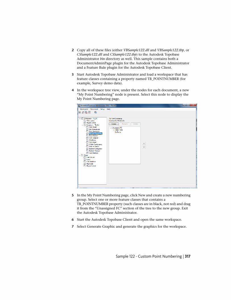
2 Copy all of these files (either VBSample122.dll and VBSample122.tbp, orCSSample122.dll and CSSample122.tbp) to the Autodesk TopobaseAdministrator bin directory as well. This sample contains both aDocumentAdminPage plugin for the Autodesk Topobase Administratorand a Feature Rule plugin for the Autodesk Topobase Client.
3 Start Autodesk Topobase Administrator and load a workspace that hasfeature classes containing a property named TB_POINTNUMBER (forexample, Survey demo data).
4 In the workspace tree view, under the nodes for each document, a new“My Point Numbering” node is present. Select this node to display theMy Point Numbering page.
5 In the My Point Numbering page, click New and create a new numberinggroup. Select one or more feature classes that contains aTB_POINTNUMBER property (such classes are in black, not red) and dragit from the “Unassigned FC” section of the tree to the new group. Exitthe Autodesk Topobase Administrator.
6 Start the Autodesk Topobase Client and open the same workspace.
7 Select Generate Graphic and generate the graphics for the workspace.
Sample 122 - Custom Point Numbering | 317
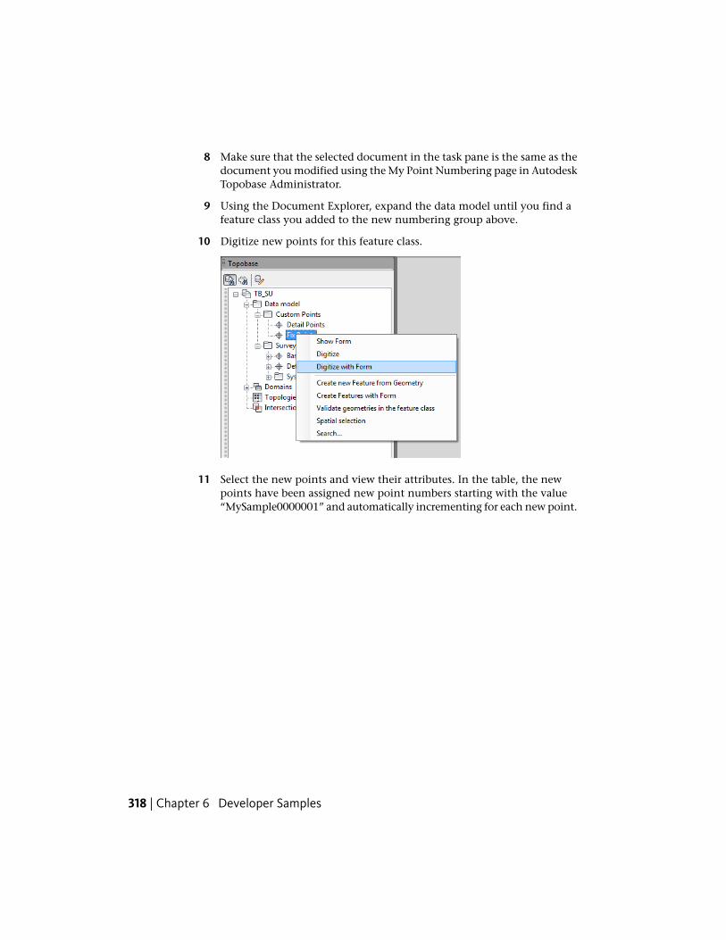
8 Make sure that the selected document in the task pane is the same as thedocument you modified using the My Point Numbering page in AutodeskTopobase Administrator.
9 Using the Document Explorer, expand the data model until you find afeature class you added to the new numbering group above.
10 Digitize new points for this feature class.
11 Select the new points and view their attributes. In the table, the newpoints have been assigned new point numbers starting with the value“MySample0000001” and automatically incrementing for each new point.
318 | Chapter 6 Developer Samples
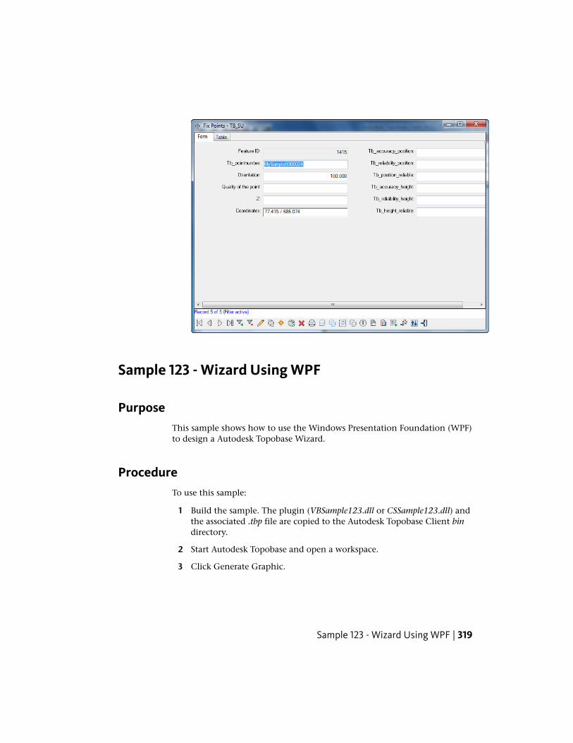
Sample 123 - Wizard Using WPF
PurposeThis sample shows how to use the Windows Presentation Foundation (WPF)to design a Autodesk Topobase Wizard.
ProcedureTo use this sample:
1 Build the sample. The plugin (VBSample123.dll or CSSample123.dll) andthe associated .tbp file are copied to the Autodesk Topobase Client bindirectory.
2 Start Autodesk Topobase and open a workspace.
3 Click Generate Graphic.
Sample 123 - Wizard Using WPF | 319
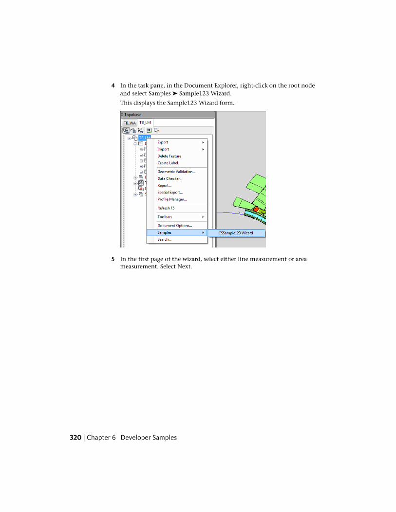
4 In the task pane, in the Document Explorer, right-click on the root nodeand select Samples ➤ Sample123 Wizard.
This displays the Sample123 Wizard form.
5 In the first page of the wizard, select either line measurement or areameasurement. Select Next.
320 | Chapter 6 Developer Samples
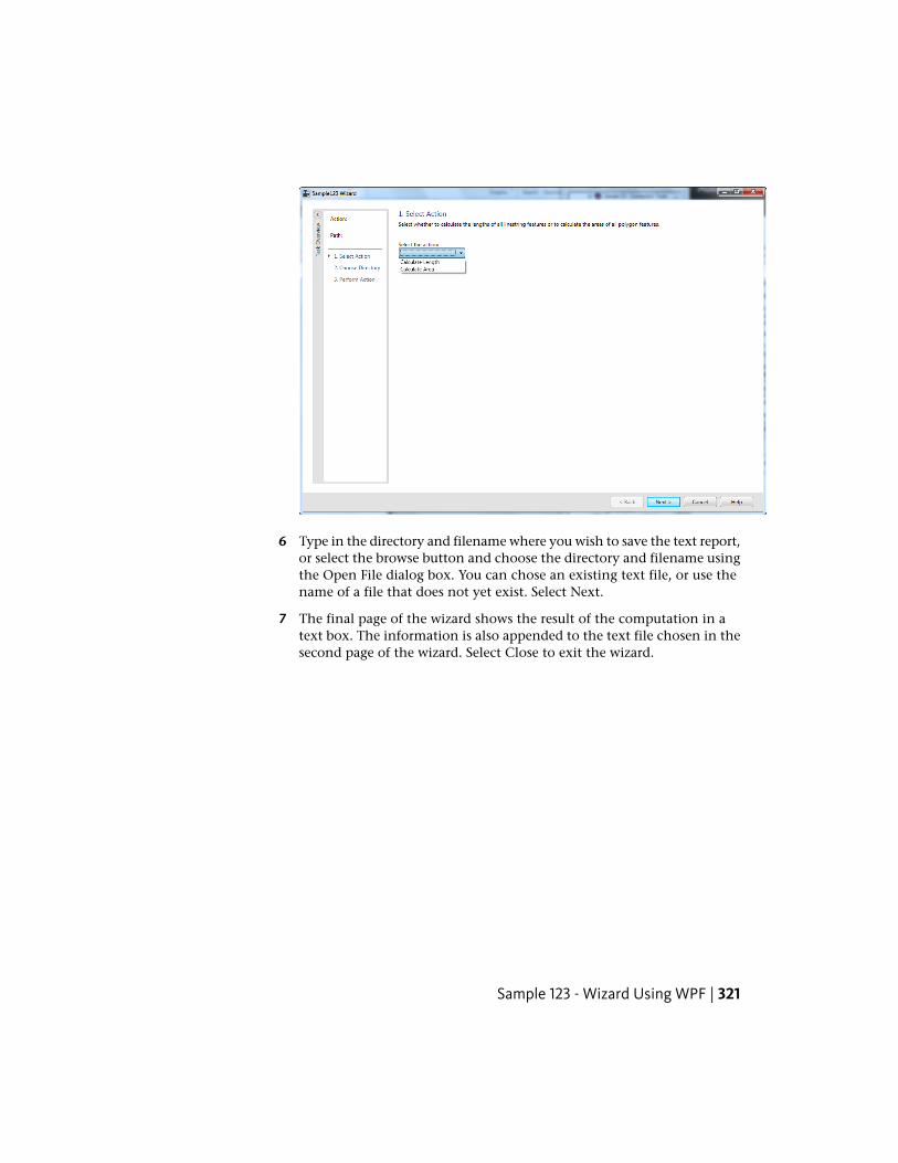
6 Type in the directory and filename where you wish to save the text report,or select the browse button and choose the directory and filename usingthe Open File dialog box. You can chose an existing text file, or use thename of a file that does not yet exist. Select Next.
7 The final page of the wizard shows the result of the computation in atext box. The information is also appended to the text file chosen in thesecond page of the wizard. Select Close to exit the wizard.
Sample 123 - Wizard Using WPF | 321
Sample 124 - Client Plot Commands
PurposeThis sample shows how to modify the context menus shown in the PlotExplorer. Specifically, it shows how to add two new Quick Edit menu itemsto the right-click context menu available for plot instances.
ProcedureTo use this sample:
1 In Visual Studio, open the appropriate Sample 124 solution file(VBSample124.sln or CSSample124.sln) and re-set the correct paths for thereferenced assemblies acmdg.dll and acdbmgd.dll. Remove the existingentries and re-add the same assemblies by browsing to the installationfolder of Autodesk Topobase Client (for example, C:\ProgramFiles\Autodesk\Autodesk Topobase Client <yyyy>, where <yyyy> is thecurrent Autodesk Topobase version number).
322 | Chapter 6 Developer Samples
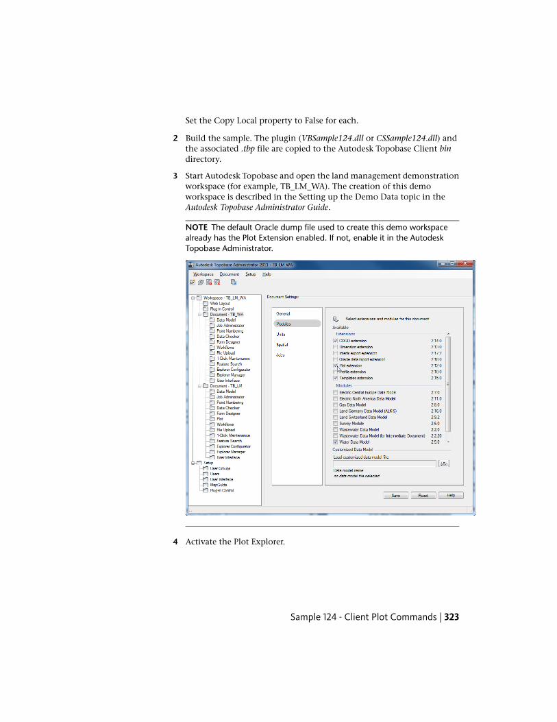
Set the Copy Local property to False for each.
2 Build the sample. The plugin (VBSample124.dll or CSSample124.dll) andthe associated .tbp file are copied to the Autodesk Topobase Client bindirectory.
3 Start Autodesk Topobase and open the land management demonstrationworkspace (for example, TB_LM_WA). The creation of this demoworkspace is described in the Setting up the Demo Data topic in theAutodesk Topobase Administrator Guide.
NOTE The default Oracle dump file used to create this demo workspacealready has the Plot Extension enabled. If not, enable it in the AutodeskTopobase Administrator.
4 Activate the Plot Explorer.
Sample 124 - Client Plot Commands | 323
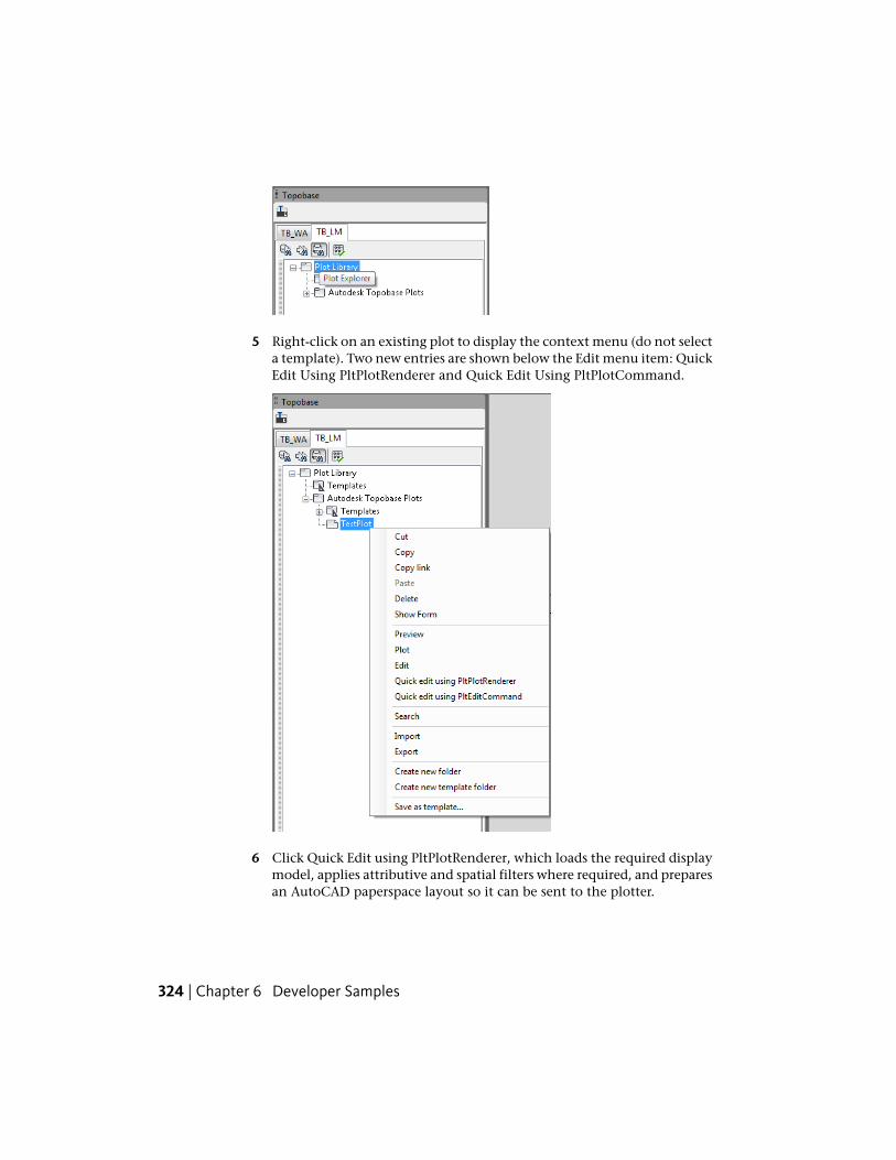
5 Right-click on an existing plot to display the context menu (do not selecta template). Two new entries are shown below the Edit menu item: QuickEdit Using PltPlotRenderer and Quick Edit Using PltPlotCommand.
6 Click Quick Edit using PltPlotRenderer, which loads the required displaymodel, applies attributive and spatial filters where required, and preparesan AutoCAD paperspace layout so it can be sent to the plotter.
324 | Chapter 6 Developer Samples
or
Click Quick Edit using PltPlotCommand, which takes the current selectedplot node, creates an AutoCAD layout, and finally opens AutoCAD's plotdialog.
NOTE Opening a plot for editing from one of the two new menu entries preventsany display model from being loaded. Depending on the number of mapplaceholders available on the plot and the complexity of the referenced displaymodels, rendering time can significantly improve. However, the user no longersees a preview of the content shown by each map placeholder.
Sample 125 - Profile
PurposeThis sample shows how to create a simple profile manager using the providedAutodesk Topobase Profile-related APIs, which include the following functions:
■ load existing profiles
■ update any specified profile
■ delete any specified profile
■ create a new profile with a specified profile definition
ProcedureTo use this sample:
1 Build the sample. The plugin (VBSample125.dll or CSSample125.dll) andthe associated .tbp file are copied to the Autodesk Topobase Client bindirectory.
2 Start Autodesk Topobase and open a workspace that contains a documentconfigured with Autodesk Topobase Profile Extensions (for example,TB_WW, the wastewater demonstration workspace). The creation of demoworkspaces is described in the Setting up the Demo Data topic in theAutodesk Topobase Administrator Guide.
Sample 125 - Profile | 325
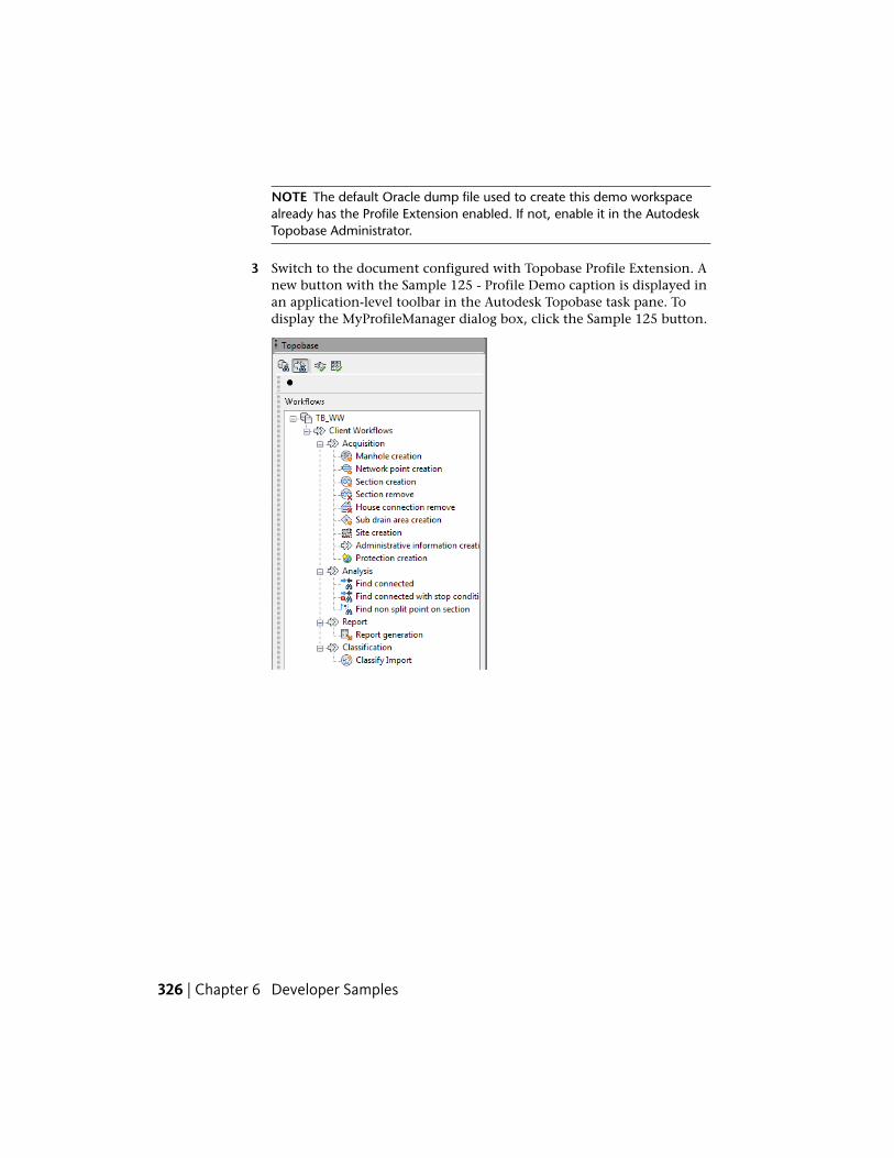
NOTE The default Oracle dump file used to create this demo workspacealready has the Profile Extension enabled. If not, enable it in the AutodeskTopobase Administrator.
3 Switch to the document configured with Topobase Profile Extension. Anew button with the Sample 125 - Profile Demo caption is displayed inan application-level toolbar in the Autodesk Topobase task pane. Todisplay the MyProfileManager dialog box, click the Sample 125 button.
326 | Chapter 6 Developer Samples
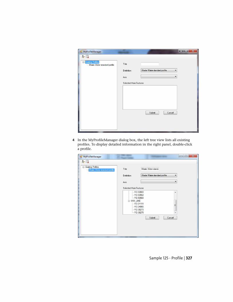
4 In the MyProfileManager dialog box, the left tree view lists all existingprofiles. To display detailed information in the right panel, double-clicka profile.
Sample 125 - Profile | 327
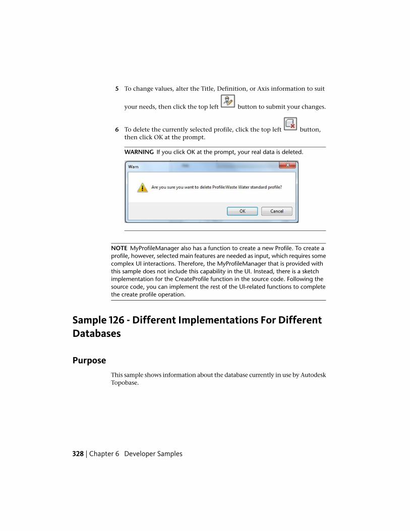
5 To change values, alter the Title, Definition, or Axis information to suit
your needs, then click the top left button to submit your changes.
6 To delete the currently selected profile, click the top left button,then click OK at the prompt.
WARNING If you click OK at the prompt, your real data is deleted.
NOTE MyProfileManager also has a function to create a new Profile. To create aprofile, however, selected main features are needed as input, which requires somecomplex UI interactions. Therefore, the MyProfileManager that is provided withthis sample does not include this capability in the UI. Instead, there is a sketchimplementation for the CreateProfile function in the source code. Following thesource code, you can implement the rest of the UI-related functions to completethe create profile operation.
Sample 126 - Different Implementations For DifferentDatabases
PurposeThis sample shows information about the database currently in use by AutodeskTopobase.
328 | Chapter 6 Developer Samples
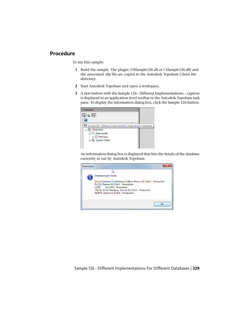
ProcedureTo use this sample:
1 Build the sample. The plugin (VBSample126.dll or CSSample126.dll) andthe associated .tbp file are copied to the Autodesk Topobase Client bindirectory.
2 Start Autodesk Topobase and open a workspace.
3 A new button with the Sample 126 - Different Implementations... captionis displayed in an application-level toolbar in the Autodesk Topobase taskpane. To display the information dialog box, click the Sample 126 button.
An information dialog box is displayed that lists the details of the databasecurrently in use by Autodesk Topobase.
Sample 126 - Different Implementations For Different Databases | 329
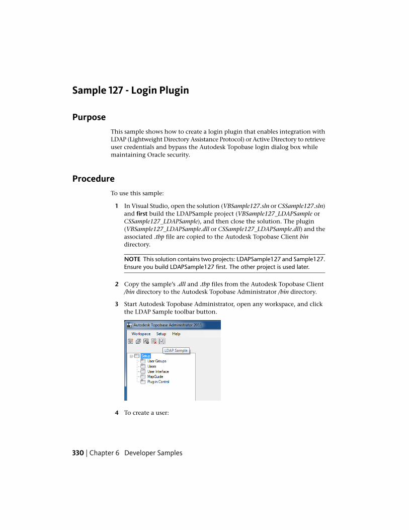
Sample 127 - Login Plugin
PurposeThis sample shows how to create a login plugin that enables integration withLDAP (Lightweight Directory Assistance Protocol) or Active Directory to retrieveuser credentials and bypass the Autodesk Topobase login dialog box whilemaintaining Oracle security.
ProcedureTo use this sample:
1 In Visual Studio, open the solution (VBSample127.sln or CSSample127.sln)and first build the LDAPSample project (VBSample127_LDAPSample orCSSample127_LDAPSample), and then close the solution. The plugin(VBSample127_LDAPSample.dll or CSSample127_LDAPSample.dll) and theassociated .tbp file are copied to the Autodesk Topobase Client bindirectory.
NOTE This solution contains two projects: LDAPSample127 and Sample127.Ensure you build LDAPSample127 first. The other project is used later.
2 Copy the sample’s .dll and .tbp files from the Autodesk Topobase Client/bin directory to the Autodesk Topobase Administrator /bin directory.
3 Start Autodesk Topobase Administrator, open any workspace, and clickthe LDAP Sample toolbar button.
4 To create a user:
330 | Chapter 6 Developer Samples
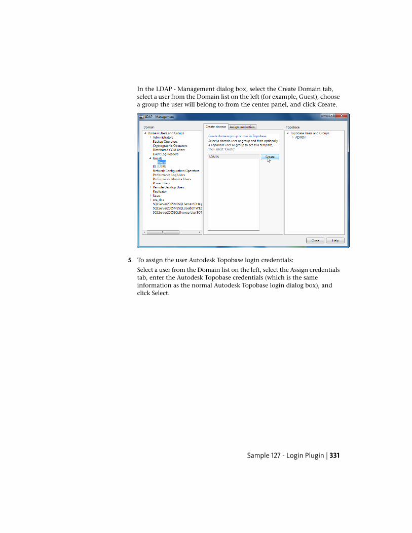
In the LDAP - Management dialog box, select the Create Domain tab,select a user from the Domain list on the left (for example, Guest), choosea group the user will belong to from the center panel, and click Create.
5 To assign the user Autodesk Topobase login credentials:
Select a user from the Domain list on the left, select the Assign credentialstab, enter the Autodesk Topobase credentials (which is the sameinformation as the normal Autodesk Topobase login dialog box), andclick Select.
Sample 127 - Login Plugin | 331
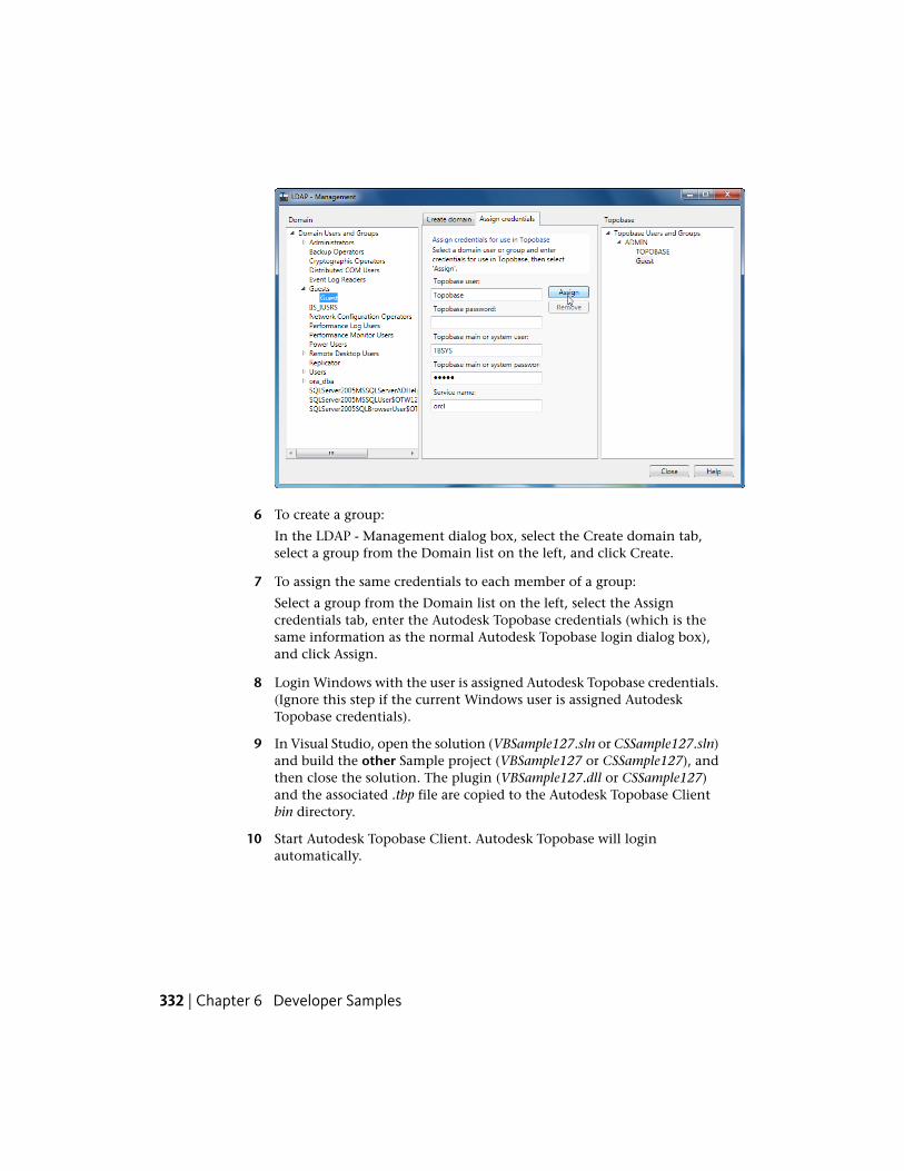
6 To create a group:
In the LDAP - Management dialog box, select the Create domain tab,select a group from the Domain list on the left, and click Create.
7 To assign the same credentials to each member of a group:
Select a group from the Domain list on the left, select the Assigncredentials tab, enter the Autodesk Topobase credentials (which is thesame information as the normal Autodesk Topobase login dialog box),and click Assign.
8 Login Windows with the user is assigned Autodesk Topobase credentials.(Ignore this step if the current Windows user is assigned AutodeskTopobase credentials).
9 In Visual Studio, open the solution (VBSample127.sln or CSSample127.sln)and build the other Sample project (VBSample127 or CSSample127), andthen close the solution. The plugin (VBSample127.dll or CSSample127)and the associated .tbp file are copied to the Autodesk Topobase Clientbin directory.
10 Start Autodesk Topobase Client. Autodesk Topobase will loginautomatically.
332 | Chapter 6 Developer Samples
Sample 128 - Database Independent
PurposeThis sample shows how to develop in a database-independet way to enablethe same code to run with databases other than Oracle (for example, SQLite).
Specifically, the sample details how to:
■ Get datastructure information about a database (Tables/Views/Synonyms)
■ Create datastructure (Tables, Attributes, Indexes, Sequences)
■ Drop a Table
■ Create different SQL calls for each database type
■ Use the database-independent Query Class, which is a way to write querieswithout using plain SQL
■ Connect to databases
■ Insert data into a Table
ProcedureTo use this sample:
1 Build the sample. The plugin CSSample128.dll and the associated .tbp fileare copied to the Autodesk Topobase Client bin directory.
2 Start Autodesk Topobase and open the TBSAMPLE workspace.
3 Click the Sample 128 - DBIndependent toolbar button.
Sample 128 - Database Independent | 333
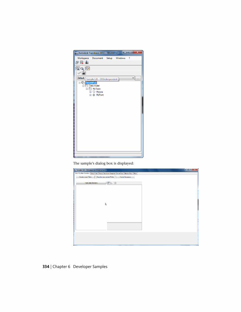
The sample’s dialog box is displayed:
334 | Chapter 6 Developer Samples
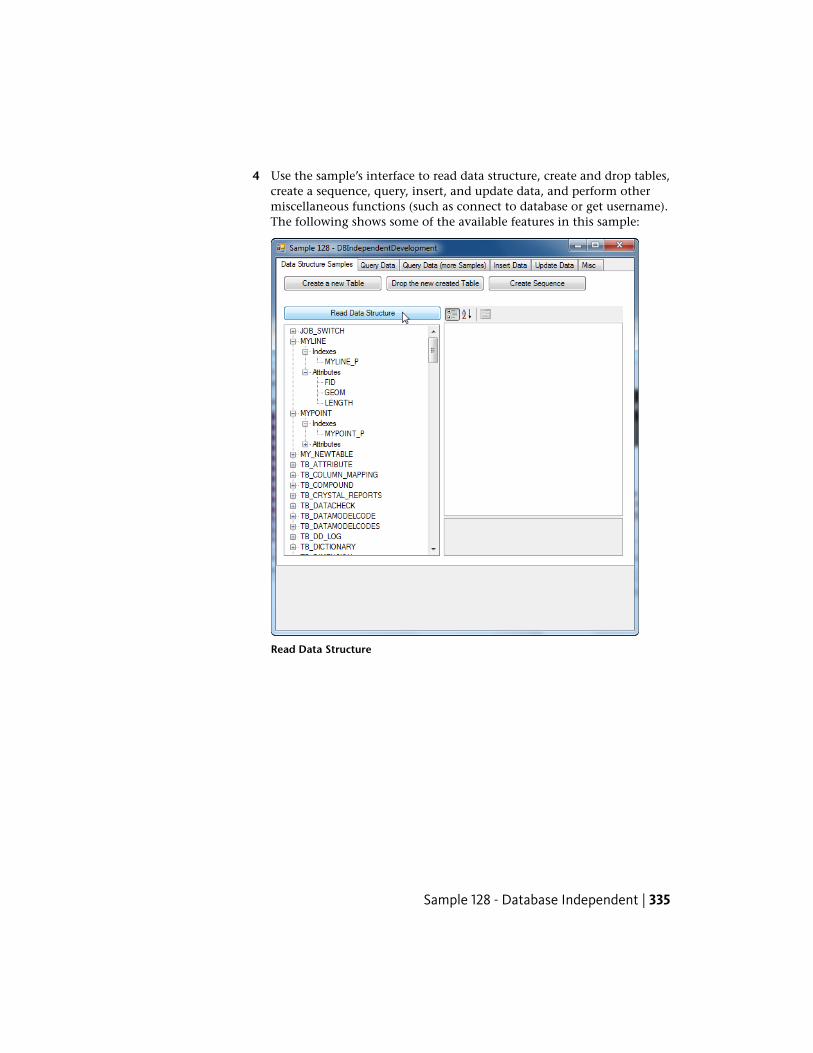
4 Use the sample’s interface to read data structure, create and drop tables,create a sequence, query, insert, and update data, and perform othermiscellaneous functions (such as connect to database or get username).The following shows some of the available features in this sample:
Read Data Structure
Sample 128 - Database Independent | 335
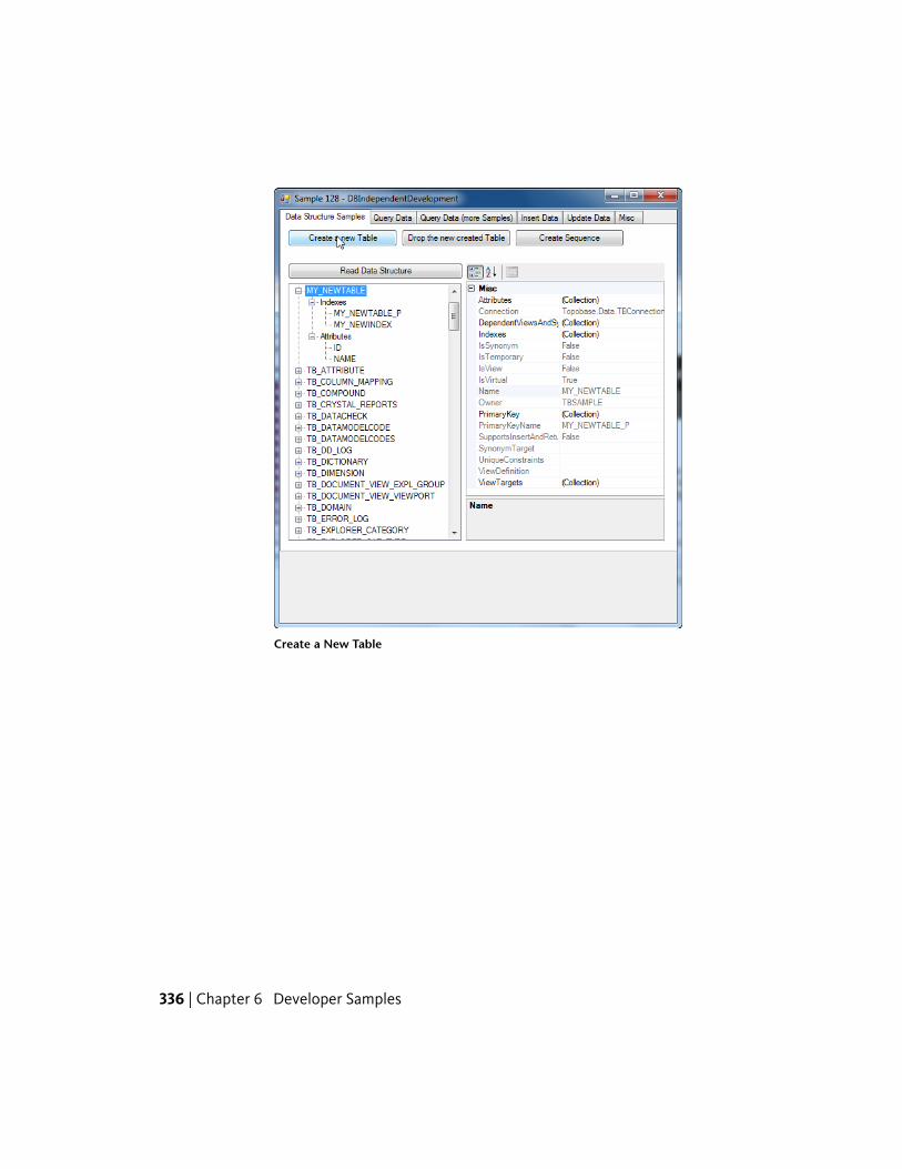
Create a New Table
336 | Chapter 6 Developer Samples
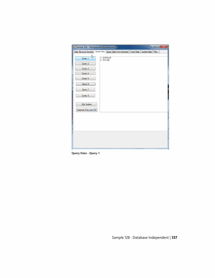
Query Data - Query 1
Sample 128 - Database Independent | 337
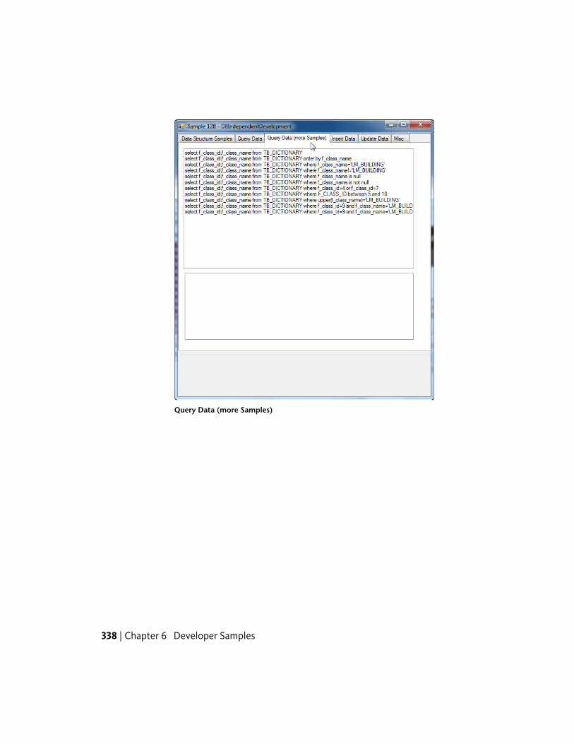
Query Data (more Samples)
338 | Chapter 6 Developer Samples
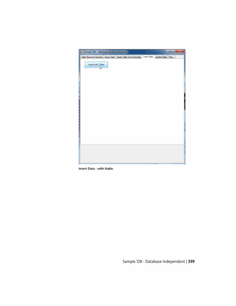
Insert Data - with Itable
Sample 128 - Database Independent | 339
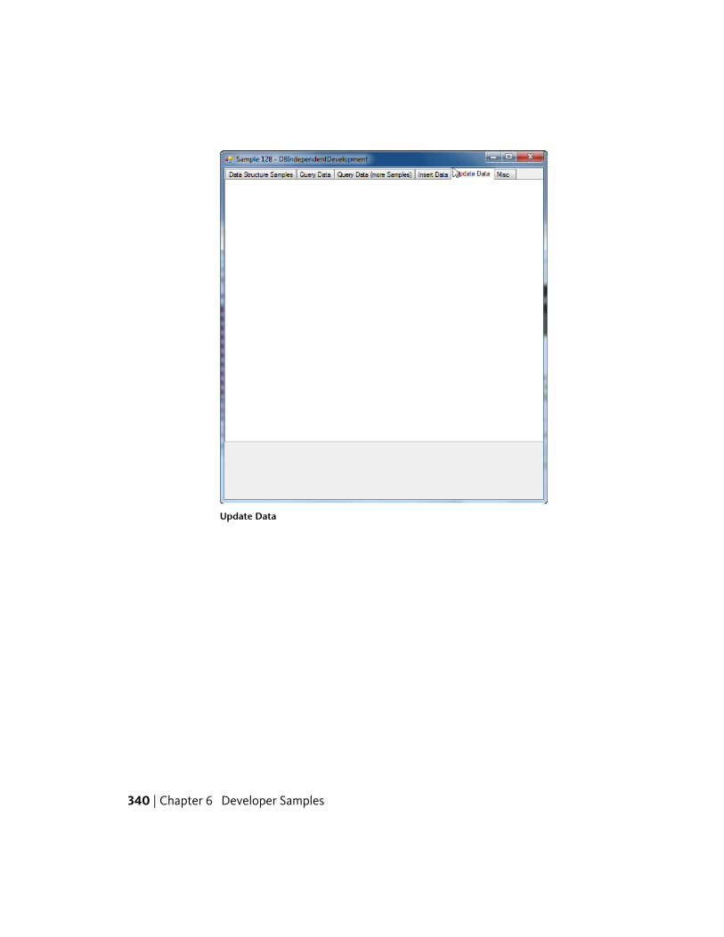
Update Data
340 | Chapter 6 Developer Samples
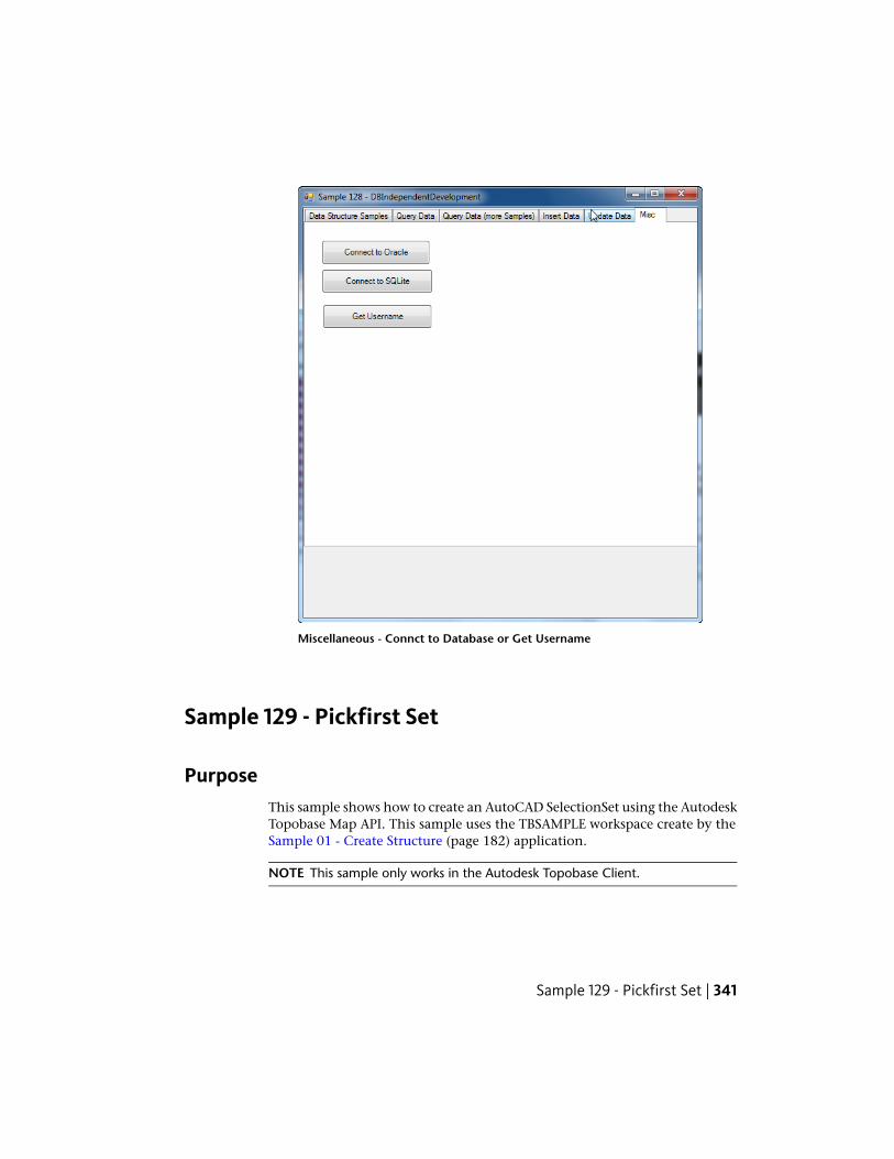
Miscellaneous - Connct to Database or Get Username
Sample 129 - Pickfirst Set
PurposeThis sample shows how to create an AutoCAD SelectionSet using the AutodeskTopobase Map API. This sample uses the TBSAMPLE workspace create by theSample 01 - Create Structure (page 182) application.
NOTE This sample only works in the Autodesk Topobase Client.
Sample 129 - Pickfirst Set | 341
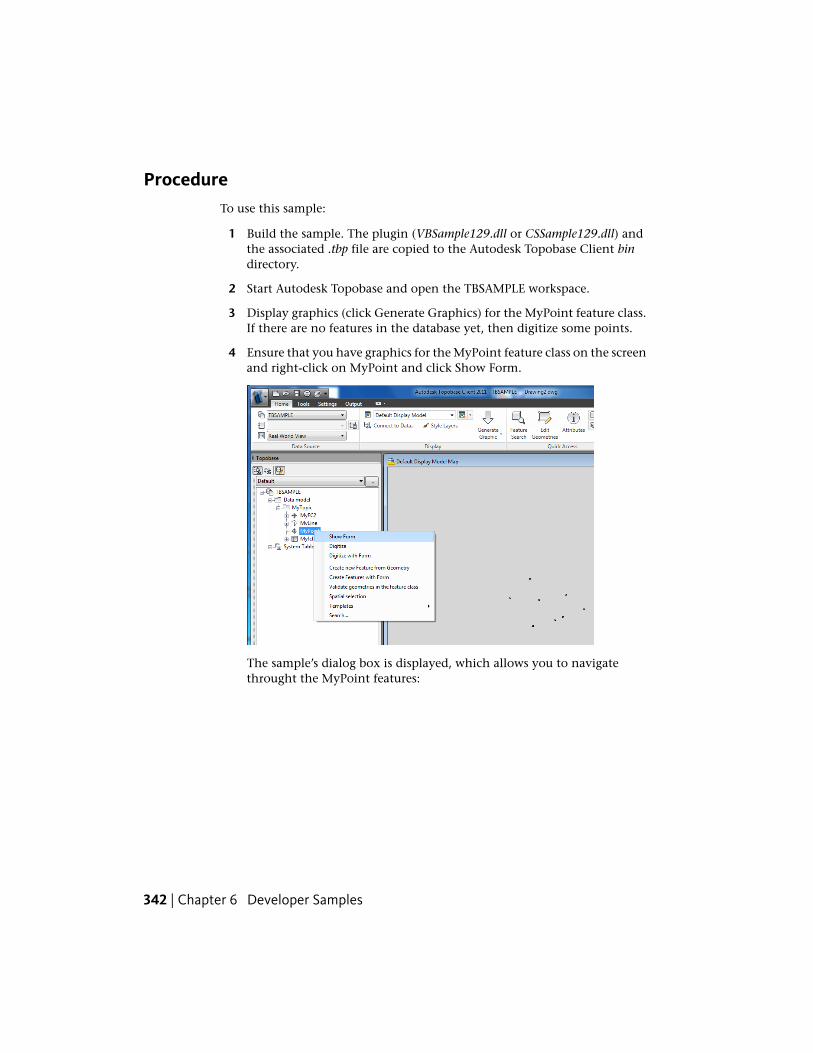
ProcedureTo use this sample:
1 Build the sample. The plugin (VBSample129.dll or CSSample129.dll) andthe associated .tbp file are copied to the Autodesk Topobase Client bindirectory.
2 Start Autodesk Topobase and open the TBSAMPLE workspace.
3 Display graphics (click Generate Graphics) for the MyPoint feature class.If there are no features in the database yet, then digitize some points.
4 Ensure that you have graphics for the MyPoint feature class on the screenand right-click on MyPoint and click Show Form.
The sample’s dialog box is displayed, which allows you to navigatethrought the MyPoint features:
342 | Chapter 6 Developer Samples
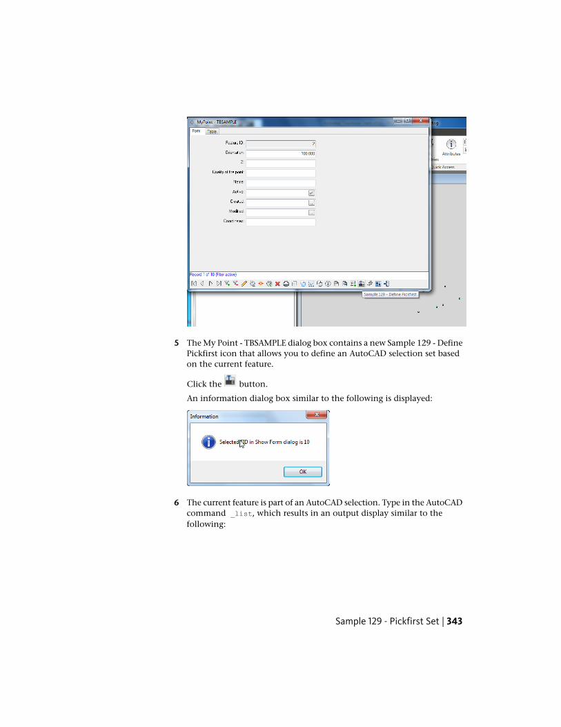
5 The My Point - TBSAMPLE dialog box contains a new Sample 129 - DefinePickfirst icon that allows you to define an AutoCAD selection set basedon the current feature.
Click the button.
An information dialog box similar to the following is displayed:
6 The current feature is part of an AutoCAD selection. Type in the AutoCADcommand _list, which results in an output display similar to thefollowing:
Sample 129 - Pickfirst Set | 343
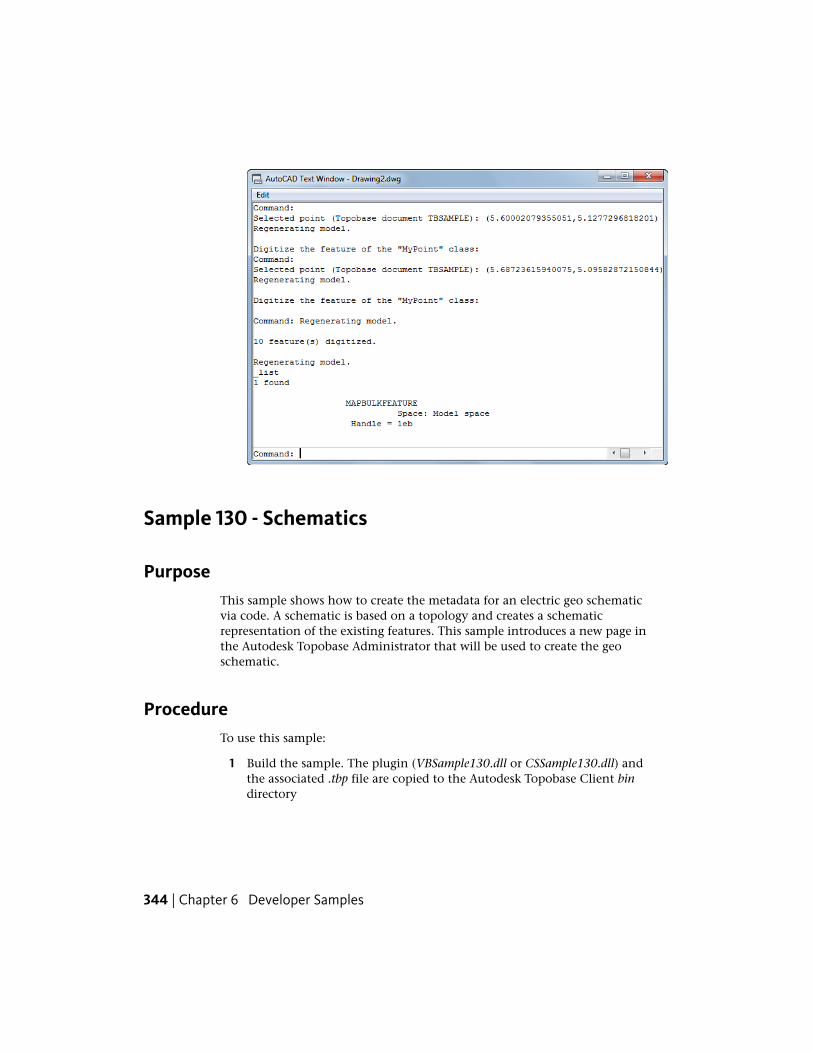
Sample 130 - Schematics
PurposeThis sample shows how to create the metadata for an electric geo schematicvia code. A schematic is based on a topology and creates a schematicrepresentation of the existing features. This sample introduces a new page inthe Autodesk Topobase Administrator that will be used to create the geoschematic.
ProcedureTo use this sample:
1 Build the sample. The plugin (VBSample130.dll or CSSample130.dll) andthe associated .tbp file are copied to the Autodesk Topobase Client bindirectory
344 | Chapter 6 Developer Samples
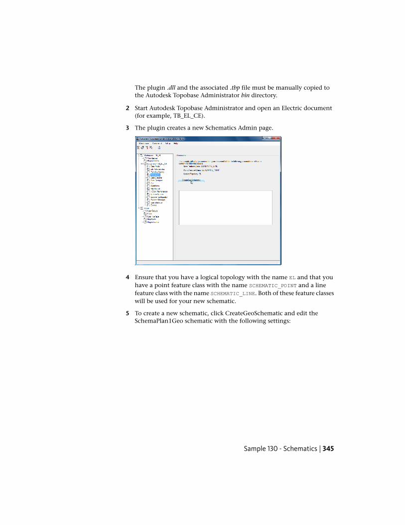
The plugin .dll and the associated .tbp file must be manually copied tothe Autodesk Topobase Administrator bin directory.
2 Start Autodesk Topobase Administrator and open an Electric document(for example, TB_EL_CE).
3 The plugin creates a new Schematics Admin page.
4 Ensure that you have a logical topology with the name EL and that youhave a point feature class with the name SCHEMATIC_POINT and a linefeature class with the name SCHEMATIC_LINE. Both of these feature classeswill be used for your new schematic.
5 To create a new schematic, click CreateGeoSchematic and edit theSchemaPlan1Geo schematic with the following settings:
Sample 130 - Schematics | 345
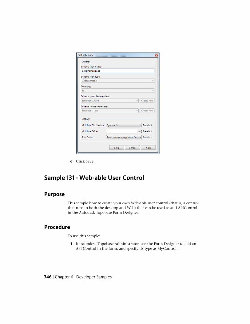
6 Click Save.
Sample 131 - Web-able User Control
PurposeThis sample how to create your own Web-able user control (that is, a controlthat runs in both the desktop and Web) that can be used as and APIControlin the Autodesk Topobase Form Designer.
ProcedureTo use this sample:
1 In Autodesk Topobase Administrator, use the Form Designer to add anAPI Control in the form, and specify its type as MyControl.
346 | Chapter 6 Developer Samples
2 Open the .tbp file and replace the DialogPlugIn’s name attribute with thetable’s name.
3 Replace $APICONTROL1 in MyDialog_Load function codes with yournew API Control name.
Sample 133 - Start Client Via Batch
PurposeThis sample how to call Autodesk Topobase Client (Topobase.exe) via batch.
ProcedureTo use this sample:
1 Autodesk Topobase can be started using a command-line call toTopobase.exe (which is located in the Autodesk Topobase Client bindirectory). Parameters can also be used to define users, passwords,workspaces, and other variables. For example, if you execute (all on oneline):
Topobase.exe Username=TOPOBASE;Password=TOPOBASE;tbsysusername=TB
SYS;tbsyspassword=tbsys;tbsysservice=orcl;Workspace=TB
SAMPLE;ShowReport=Test
No login dialog box is displayed and the workspace opens automatically.
2 The user-defined parameter ShowReport defines the name of the reportto be created. If the parameter exists, then we know that AutodeskTopobase is called via batch mode so it must be closed after processingis completed.
NOTE Any parameters can be added and read usingthis.Application.Desktop.GetCommandLineArg.
Sample 133 - Start Client Via Batch | 347
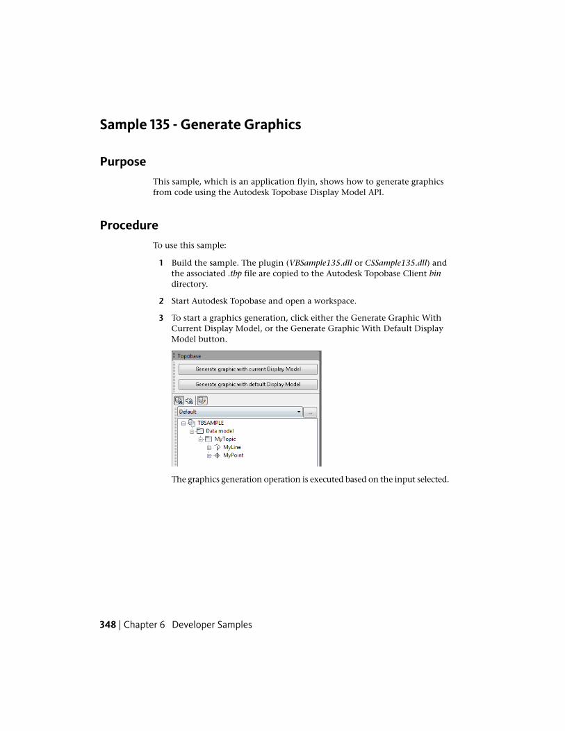
Sample 135 - Generate Graphics
PurposeThis sample, which is an application flyin, shows how to generate graphicsfrom code using the Autodesk Topobase Display Model API.
ProcedureTo use this sample:
1 Build the sample. The plugin (VBSample135.dll or CSSample135.dll) andthe associated .tbp file are copied to the Autodesk Topobase Client bindirectory.
2 Start Autodesk Topobase and open a workspace.
3 To start a graphics generation, click either the Generate Graphic WithCurrent Display Model, or the Generate Graphic With Default DisplayModel button.
The graphics generation operation is executed based on the input selected.
348 | Chapter 6 Developer Samples
Sample 136 - Extend Plot Editor
PurposeThis sample shows how to modify the right-click context menus shown inthe Plot Editor. Specifically, it shows how to add, modify, and remove itemsfrom the context menus that are available on the various nodes of the treeview shown in the plot editor.
ProcedureTo use this sample:
1 Build the sample. The plugin (VBSample136.dll or CSSample136.dll) andthe associated .tbp file are copied to the Autodesk Topobase Client bindirectory.
2 Start Autodesk Topobase and open the land management demonstrationworkspace (for example, TB_LM_WA). The creation of this demoworkspace is described in the Setting up the Demo Data topic in theAutodesk Topobase Administrator Guide).
3 Start Autodesk Topobase and open the land management demonstrationworkspace (for example, TB_LM_WA). The creation of this demoworkspace is described in the Setting up the Demo Data topic in theAutodesk Topobase Administrator Guide.
Sample 136 - Extend Plot Editor | 349
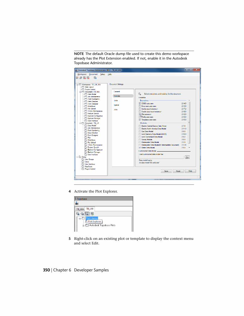
NOTE The default Oracle dump file used to create this demo workspacealready has the Plot Extension enabled. If not, enable it in the AutodeskTopobase Administrator.
4 Activate the Plot Explorer.
5 Right-click on an existing plot or template to display the context menuand select Edit.
350 | Chapter 6 Developer Samples
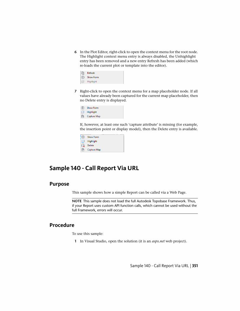
6 In the Plot Editor, right-click to open the context menu for the root node.The Highlight context menu entry is always disabled, the Unhighlightentry has been removed and a new entry Refresh has been added (whichre-loads the current plot or template into the editor).
7 Right-click to open the context menu for a map placeholder node. If allvalues have already been captured for the current map placeholder, thenno Delete entry is displayed.
If, however, at least one such ‘capture attribute’ is missing (for example,the insertion point or display model), then the Delete entry is available.
Sample 140 - Call Report Via URL
PurposeThis sample shows how a simple Report can be called via a Web Page.
NOTE This sample does not load the full Autodesk Topobase Framework. Thus,if your Report uses custom API function calls, which cannot be used without thefull Framework, errors will occur.
ProcedureTo use this sample:
1 In Visual Studio, open the solution (it is an aspx.net web project).
Sample 140 - Call Report Via URL | 351

2 Copy the .dll’s from the Autodesk Topobase Client bin directory to thebin directory of the web project.
3 Compile and run the project.
A webpage is opened that displays the Report as HTML content.
352 | Chapter 6 Developer Samples
TBP File Format
IntroductionAutodesk® Topobase is based on a plugin concept that allows developers toextend Autodesk Topobase Topobase for their own needs.
The Autodesk Topobase plugin (TBP) model serves as the basis for adding featuresto the user interface, creating workflows, setting business rules, updating thedata model, and more. Many of the standard Autodesk Topobase componentsare built using plugins.
If you want to create your own plugin, you have to create a .dll with one ormore plugin classes in it and a .tbp file that tells Autodesk Topobase whichplugin classes are implemented and where to find them. For more informationabout creating a plugin, see Quick Guide: Creating a Topobase Plugin (page 75).
You can also create one .tbp file for two or more .dll's.
A
353
Example TBP FilesThis example shows the contents of a .tbp file exposing three different pluginclasses from the library VbSample.dll:
<?xml version="1.0" encoding="utf-8"?>
<PlugIn>
<ApplicationPlugIn ClassName="MyApplication1"
AssemblyName="VbSample.dll" Namespace="VbSample"
DocumentKey="" MapName="" Priority="100"
ExecutionTargetWeb="True" ExecutionTargetDesktop="True"
Company="" Author="Michael Ross"/>
<ApplicationPlugIn ClassName="MyApplication2"
DocumentKey="" MapName="" Priority="100"
AssemblyName="VbSample.dll" Namespace="VbSample"
ExecutionTargetWeb="True" ExecutionTargetDesktop="True"
Company=”My SAmple Company" Author="Michael Ross"/>
<DocumentPlugIn ClassName="MyDocument"
AssemblyName="VbSample.dll" Namespace="VbSample"
DocumentKey="" MapName="" Priority="100"
ExecutionTargetWeb="True" ExecutionTargetDesktop="True"
Company="My Sample Company" Author="Michael Ross"/>
</PlugIn>
<?xml version="1.0" encoding="utf-8"?>
<PlugIn>
<ApplicationPlugIn ClassName="MyApplication1"/>
<ApplicationPlugIn ClassName="MyApplication2"/>
<DocumentPlugIn ClassName="MyDocument"/>
</PlugIn>
You can use the Default tag to define properties used by all plugin classes inthe library. To overwrite a single property, include the correct attribute withinthe plugin tag.
354 | Appendix A TBP File Format
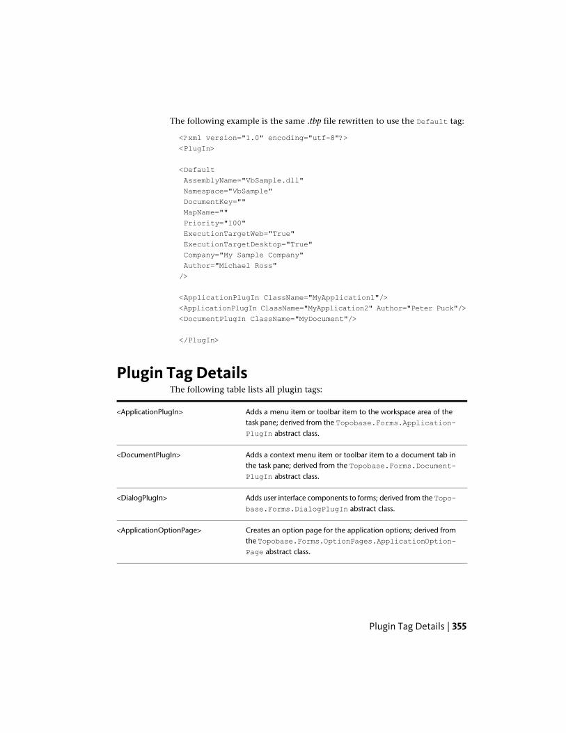
The following example is the same .tbp file rewritten to use the Default tag:
<?xml version="1.0" encoding="utf-8"?>
<PlugIn>
<Default
AssemblyName="VbSample.dll"
Namespace="VbSample"
DocumentKey=""
MapName=""
Priority="100"
ExecutionTargetWeb="True"
ExecutionTargetDesktop="True"
Company="My Sample Company"
Author="Michael Ross"
/>
<ApplicationPlugIn ClassName="MyApplication1"/>
<ApplicationPlugIn ClassName="MyApplication2" Author="Peter Puck"/>
<DocumentPlugIn ClassName="MyDocument"/>
</PlugIn>
Plugin Tag DetailsThe following table lists all plugin tags:
Adds a menu item or toolbar item to the workspace area of thetask pane; derived from the Topobase.Forms.Application-PlugIn abstract class.
<ApplicationPlugIn>
Adds a context menu item or toolbar item to a document tab inthe task pane; derived from the Topobase.Forms.Document-PlugIn abstract class.
<DocumentPlugIn>
Adds user interface components to forms; derived from the Topo-base.Forms.DialogPlugIn abstract class.
<DialogPlugIn>
Creates an option page for the application options; derived fromthe Topobase.Forms.OptionPages.ApplicationOption-Page abstract class.
<ApplicationOptionPage>
Plugin Tag Details | 355
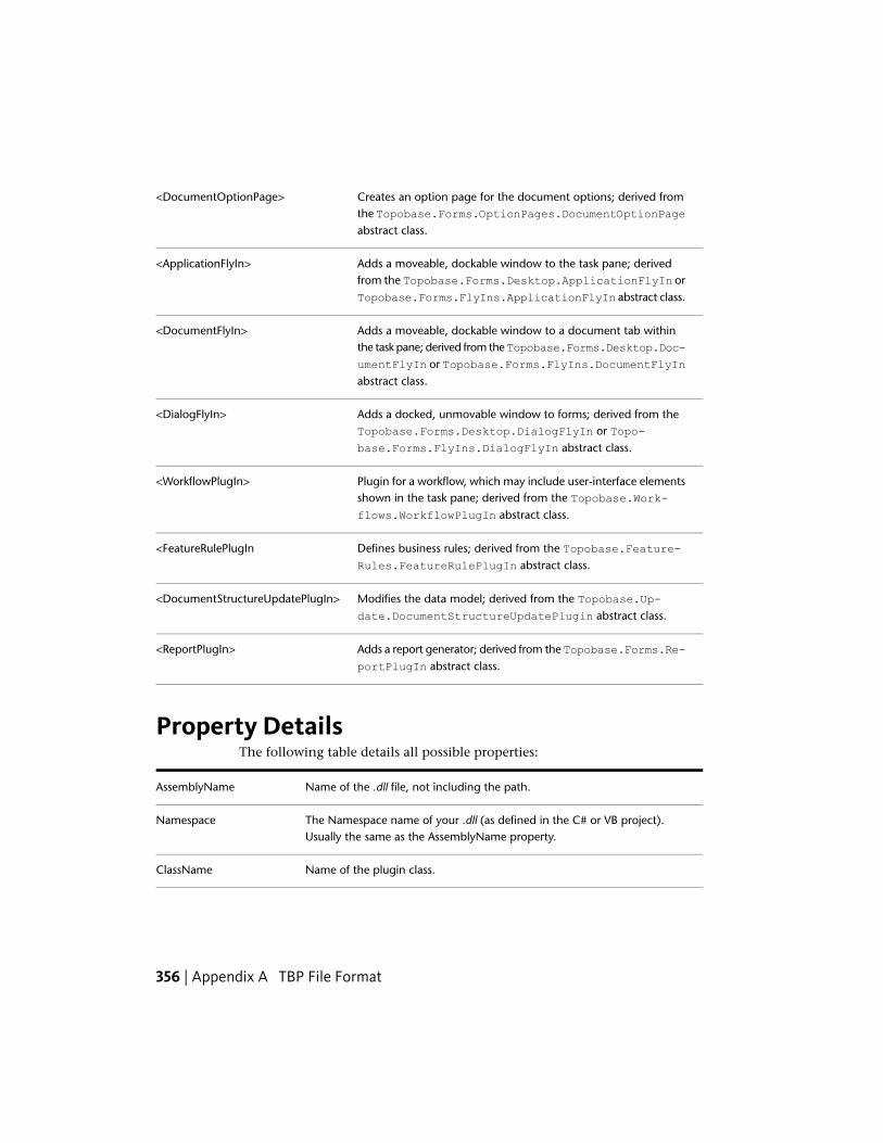
Creates an option page for the document options; derived fromthe Topobase.Forms.OptionPages.DocumentOptionPageabstract class.
<DocumentOptionPage>
Adds a moveable, dockable window to the task pane; derivedfrom the Topobase.Forms.Desktop.ApplicationFlyIn orTopobase.Forms.FlyIns.ApplicationFlyIn abstract class.
<ApplicationFlyIn>
Adds a moveable, dockable window to a document tab withinthe task pane; derived from the Topobase.Forms.Desktop.Doc-
<DocumentFlyIn>
umentFlyIn or Topobase.Forms.FlyIns.DocumentFlyInabstract class.
Adds a docked, unmovable window to forms; derived from theTopobase.Forms.Desktop.DialogFlyIn or Topo-base.Forms.FlyIns.DialogFlyIn abstract class.
<DialogFlyIn>
Plugin for a workflow, which may include user-interface elementsshown in the task pane; derived from the Topobase.Work-flows.WorkflowPlugIn abstract class.
<WorkflowPlugIn>
Defines business rules; derived from the Topobase.Feature-Rules.FeatureRulePlugIn abstract class.
<FeatureRulePlugIn
Modifies the data model; derived from the Topobase.Up-date.DocumentStructureUpdatePlugin abstract class.
<DocumentStructureUpdatePlugIn>
Adds a report generator; derived from the Topobase.Forms.Re-portPlugIn abstract class.
<ReportPlugIn>
Property DetailsThe following table details all possible properties:
Name of the .dll file, not including the path.AssemblyName
The Namespace name of your .dll (as defined in the C# or VB project).Usually the same as the AssemblyName property.
Namespace
Name of the plugin class.ClassName
356 | Appendix A TBP File Format
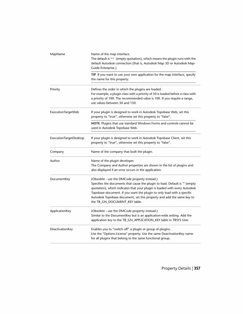
Name of the map interface.The default is "" (empty quotation), which means the plugin runs with thedefault Autodesk connection (that is, Autodesk Map 3D or Autodesk Map-Guide Enterprise.)
TIP If you want to use your own application for the map interface, specifythe name for this property.
MapName
Defines the order in which the plugins are loaded.For example, a plugin class with a priority of 50 is loaded before a class witha priority of 100. The recommended value is 100. If you require a range,use values between 50 and 150.
Priority
If your plugin is designed to work in Autodesk Topobase Web, set thisproperty to “true”, otherwise set this property to “false”.
NOTE Plugins that use standard Windows Forms and controls cannot beused in Autodesk Topobase Web.
ExecutionTargetWeb
If your plugin is designed to work in Autodesk Topobase Client, set thisproperty to “true”, otherwise set this property to “false”.
ExecutionTargetDesktop
Name of the company that built the plugin.Company
Name of the plugin developer.The Company and Author properties are shown in the list of plugins andalso displayed if an error occurs in the application.
Author
(Obsolete - use the DMCode property instead.)Specifies the documents that cause the plugin to load. Default is "" (emptyquotation), which indicates that your plugin is loaded with every Autodesk
DocumentKey
Topobase document. If you want the plugin to only load with a specificAutodesk Topobase document, set this property and add the same key tothe TB_GN_DOCUMENT_KEY table.
(Obsolete - use the DMCode property instead.)Similar to the DocumentKey but is an application-wide setting. Add theapplication key to the TB_GN_APPLICATION_KEY table in TBSYS User.
ApplicationKey
Enables you to “switch off” a plugin or group of plugins.Use the "Options-License" property. Use the same DeactivationKey namefor all plugins that belong to the same functional group.
DeactivationKey
Property Details | 357
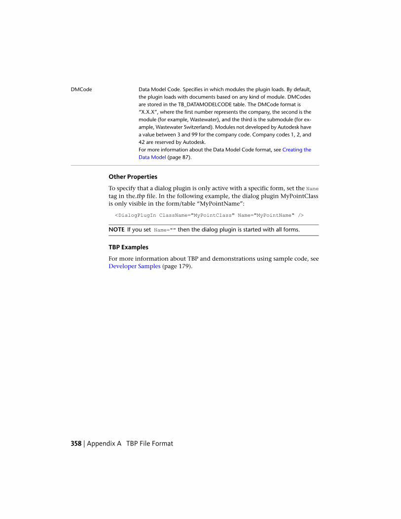
Data Model Code. Specifies in which modules the plugin loads. By default,the plugin loads with documents based on any kind of module. DMCodes
DMCode
are stored in the TB_DATAMODELCODE table. The DMCode format is“X.X.X”, where the first number represents the company, the second is themodule (for example, Wastewater), and the third is the submodule (for ex-ample, Wastewater Switzerland). Modules not developed by Autodesk havea value between 3 and 99 for the company code. Company codes 1, 2, and42 are reserved by Autodesk.For more information about the Data Model Code format, see Creating theData Model (page 87).
Other Properties
To specify that a dialog plugin is only active with a specific form, set the Nametag in the.tbp file. In the following example, the dialog plugin MyPointClassis only visible in the form/table “MyPointName”:
<DialogPlugIn ClassName="MyPointClass" Name="MyPointName" />
NOTE If you set Name="" then the dialog plugin is started with all forms.
TBP Examples
For more information about TBP and demonstrations using sample code, seeDeveloper Samples (page 179).
358 | Appendix A TBP File Format
Object Models
LegendThe following object model images represent the hierarchical links of the majorobjects and abstract classes or interfaces for most of the Autodesk TopobaseAPIs.
For more detailed information about the individual APIs, see the appropriateAutodesk Topobase API References located in the <topobase>\Help directroy:
■ Topobase_Client_API.chm
■ Topobase_Modules_API.chm
■ Topobase_ServerSite_API.chm
NOTE The API reference documentaiton is also available in Microsoft Help 2 formatfrom inside Visual Studio (F1).
B
359
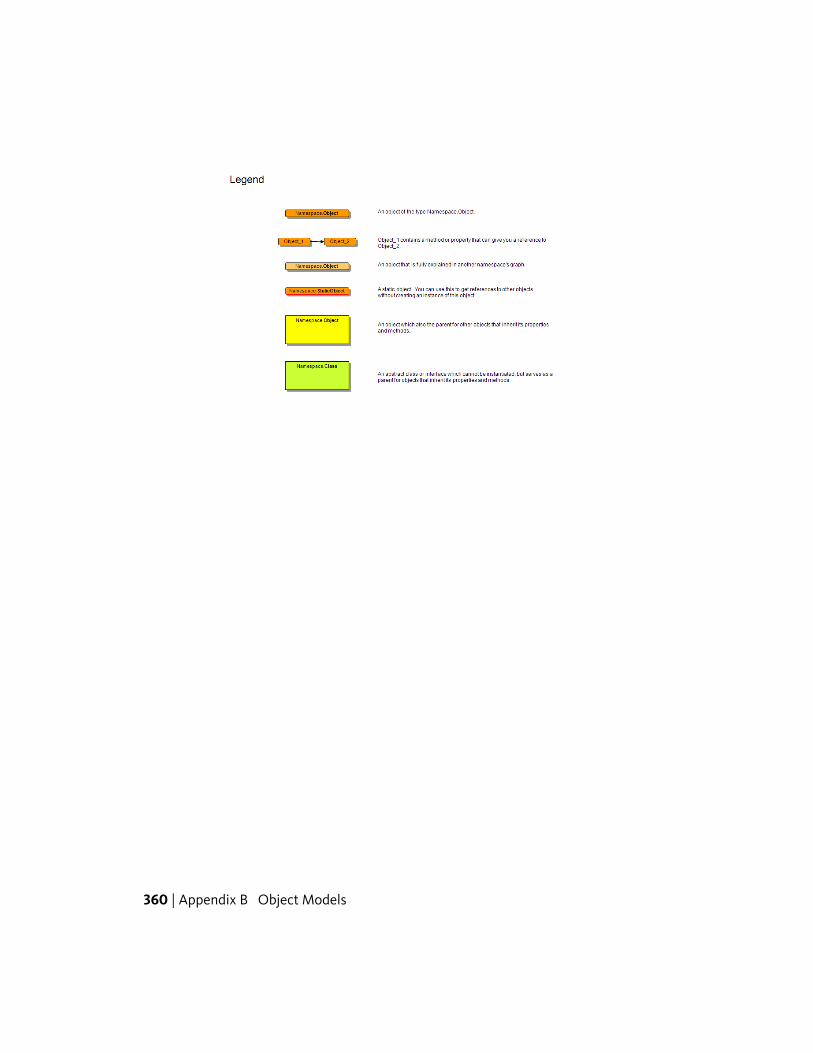
360 | Appendix B Object Models
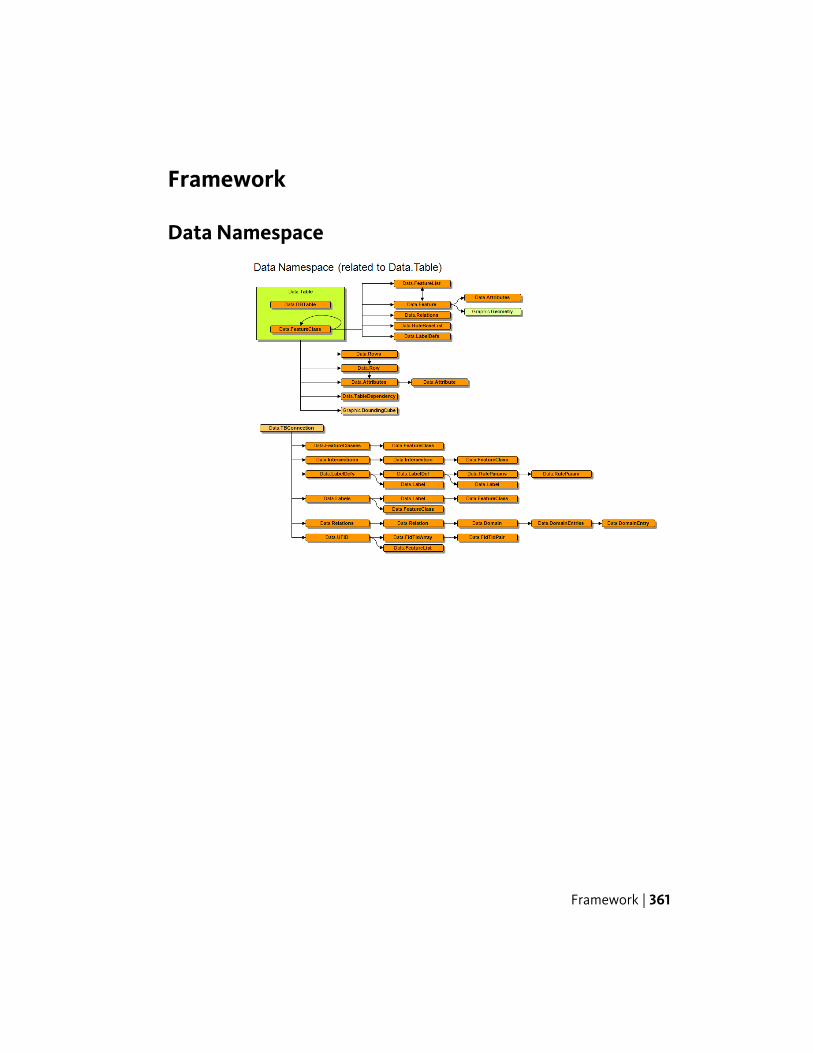
Framework
Data Namespace
Framework | 361
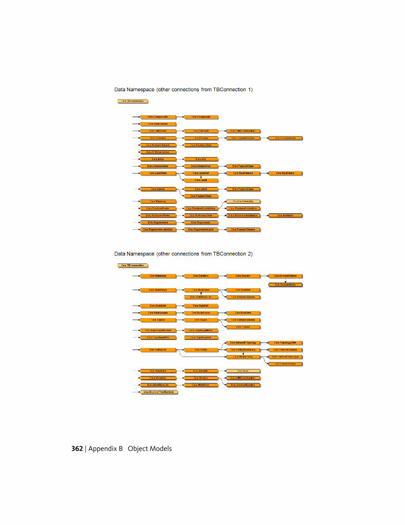
362 | Appendix B Object Models
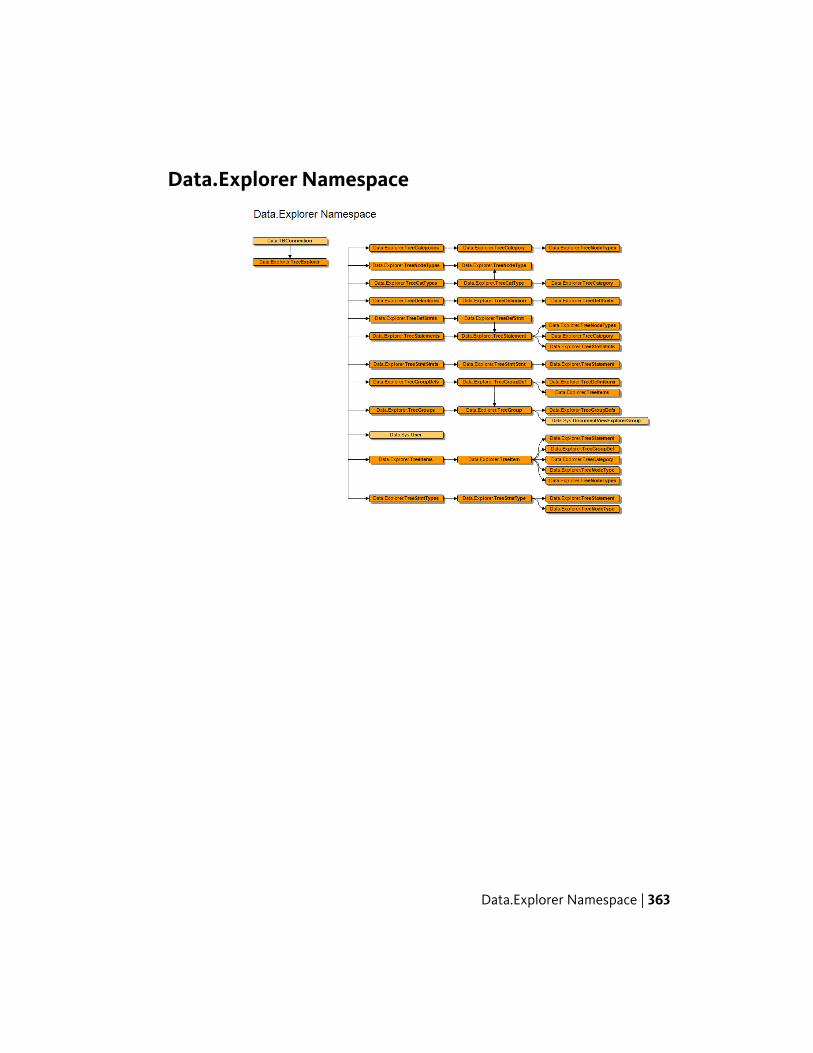
Data.Explorer Namespace
Data.Explorer Namespace | 363
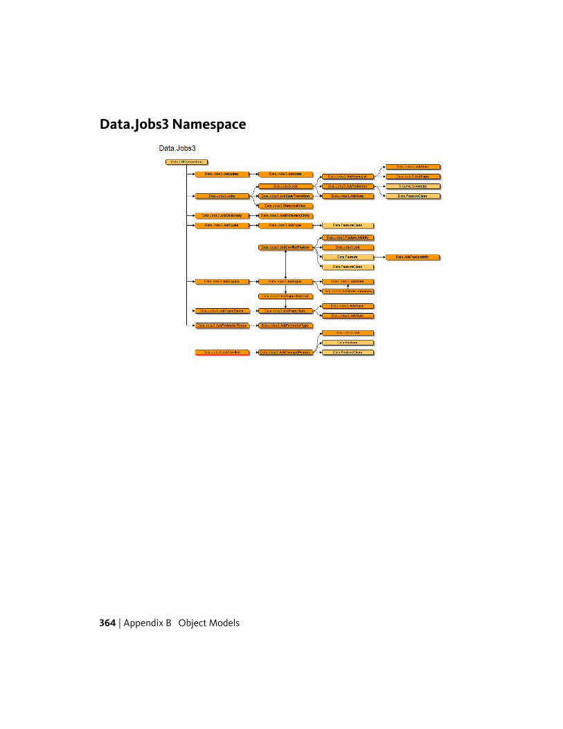
Data.Jobs3 Namespace
364 | Appendix B Object Models
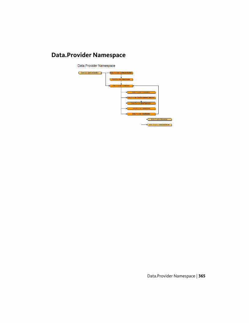
Data.Provider Namespace
Data.Provider Namespace | 365

Data.Reference and Data.Util.OperationLogNamespaces
366 | Appendix B Object Models
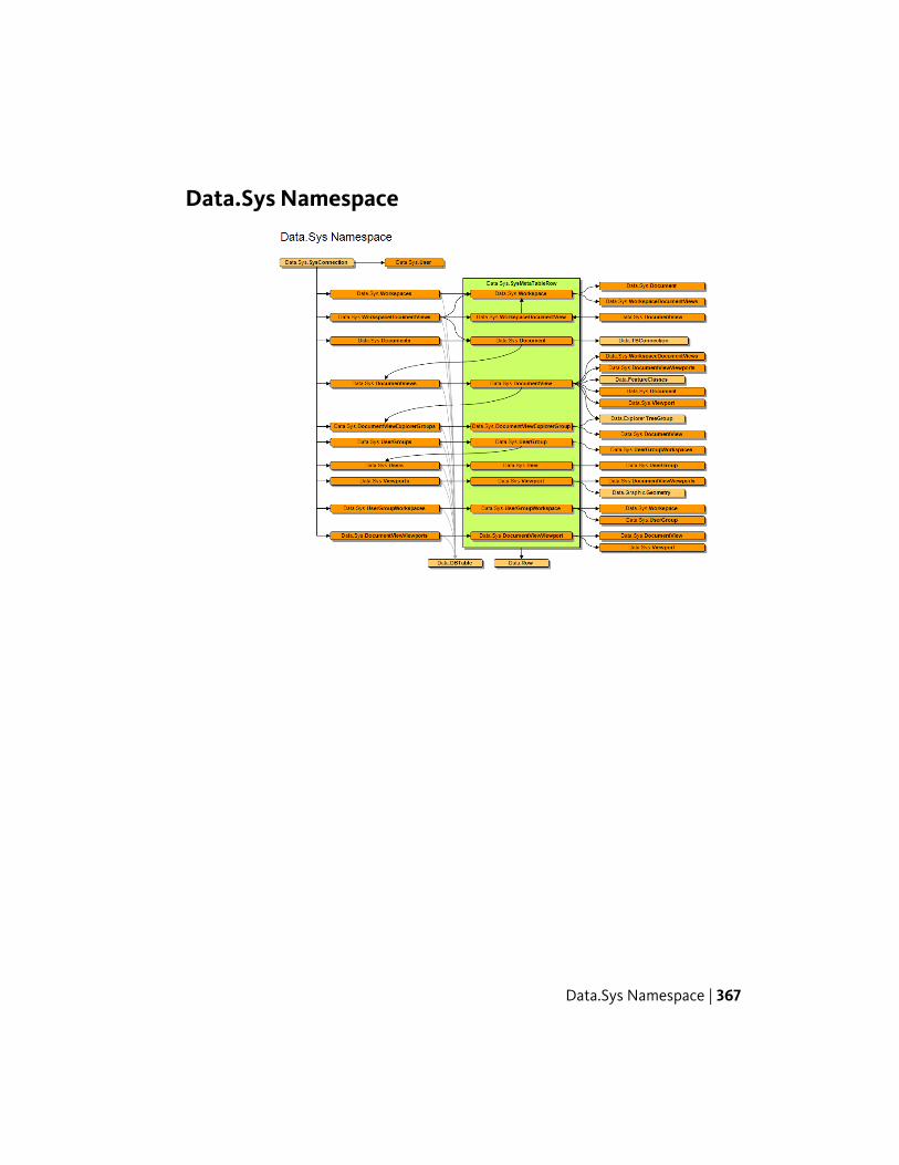
Data.Sys Namespace
Data.Sys Namespace | 367
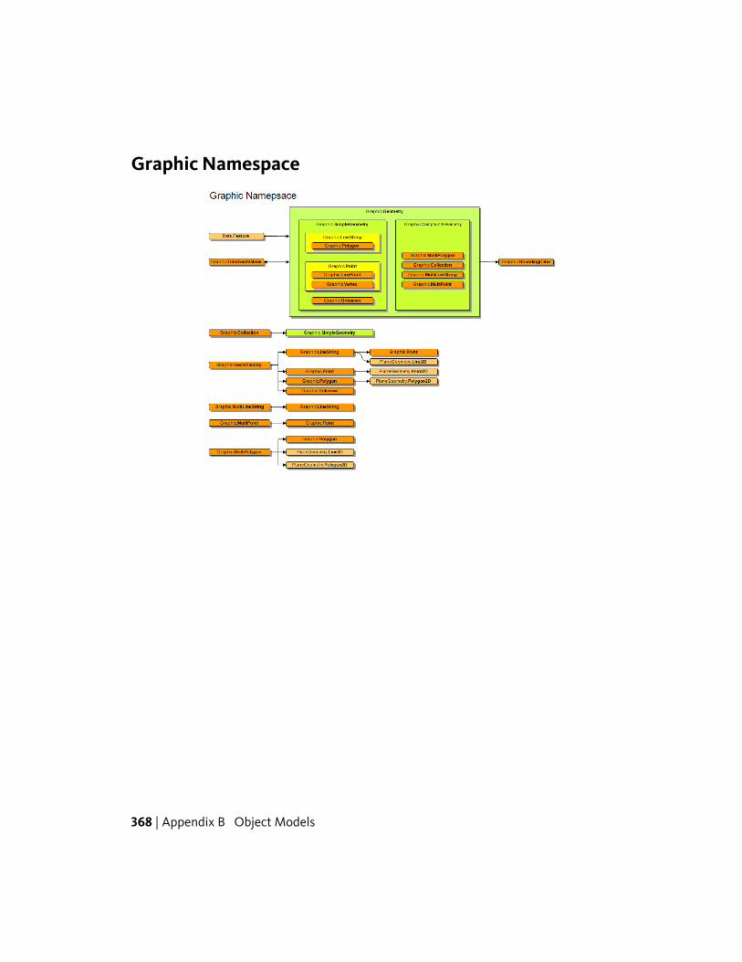
Graphic Namespace
368 | Appendix B Object Models
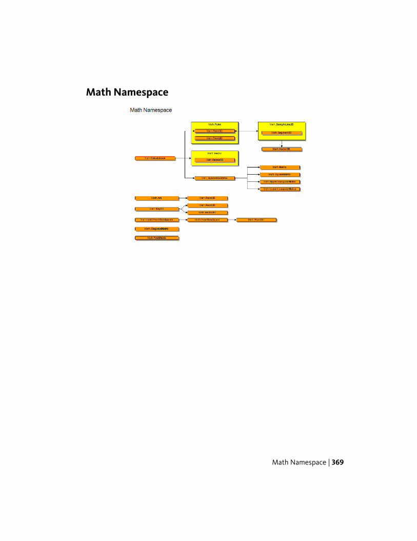
Math Namespace
Math Namespace | 369
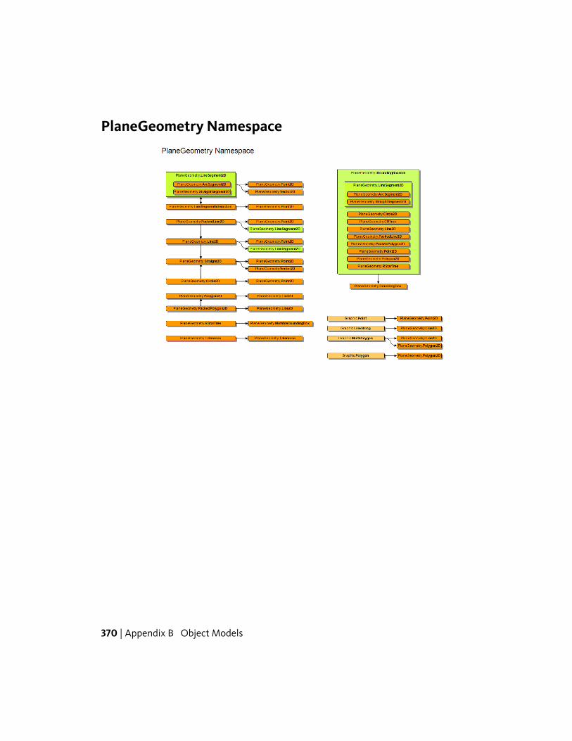
PlaneGeometry Namespace
370 | Appendix B Object Models
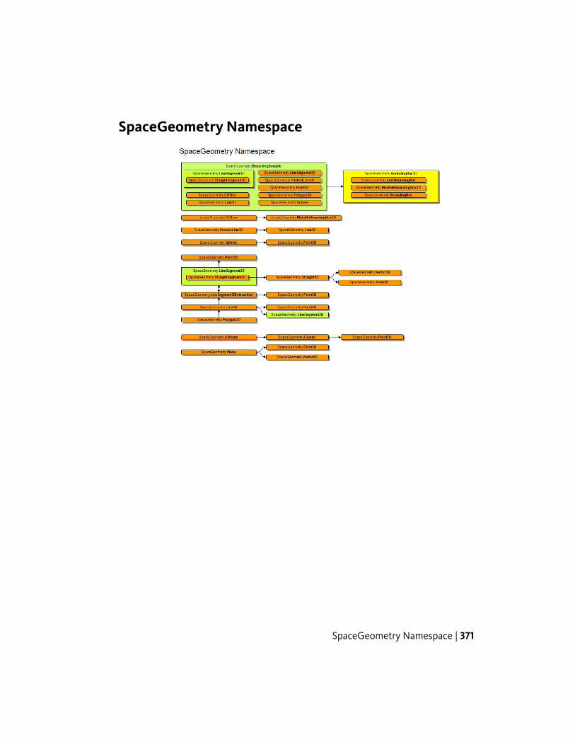
SpaceGeometry Namespace
SpaceGeometry Namespace | 371
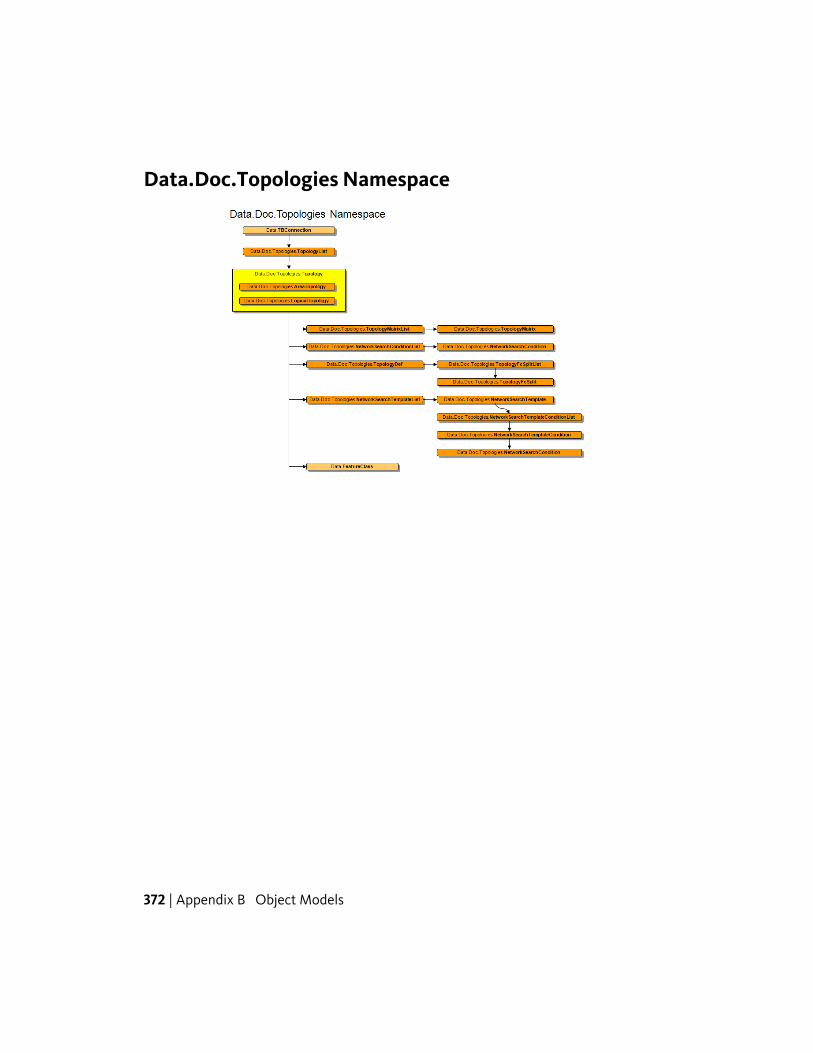
Data.Doc.Topologies Namespace
372 | Appendix B Object Models
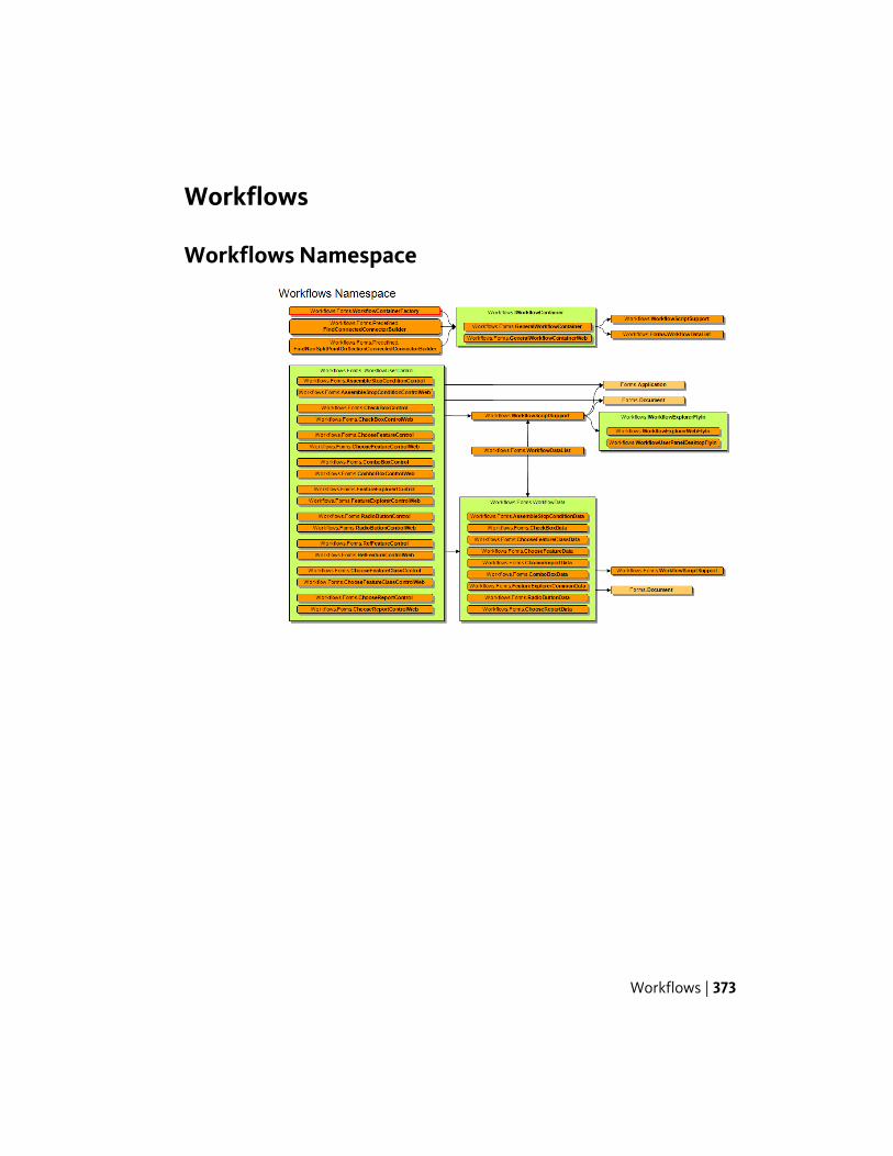
Workflows
Workflows Namespace
Workflows | 373

Area Topology
AreaTopology Namespace
374 | Appendix B Object Models
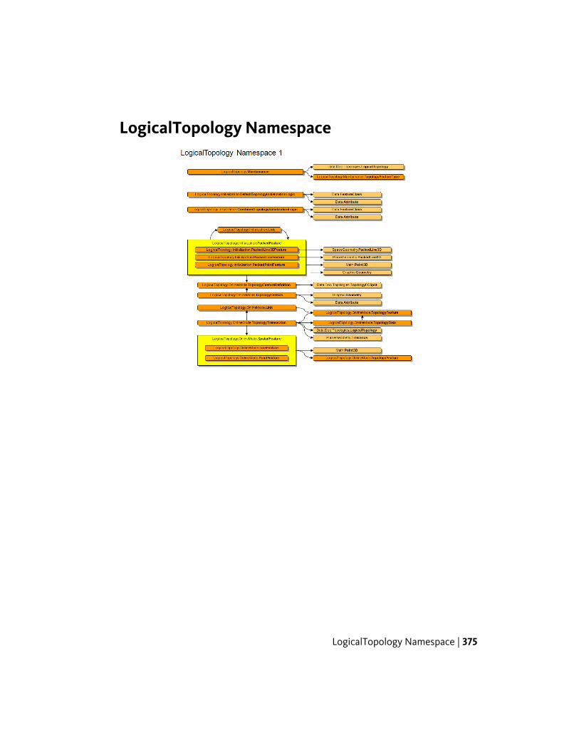
LogicalTopology Namespace
LogicalTopology Namespace | 375
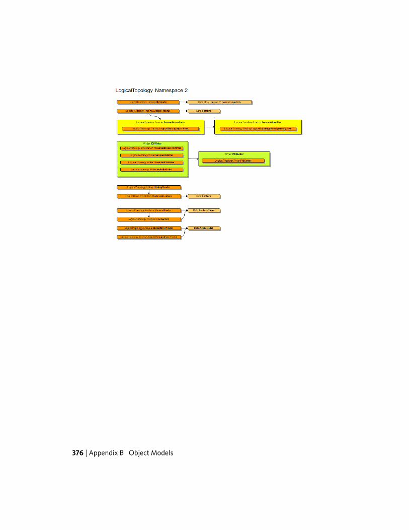
376 | Appendix B Object Models
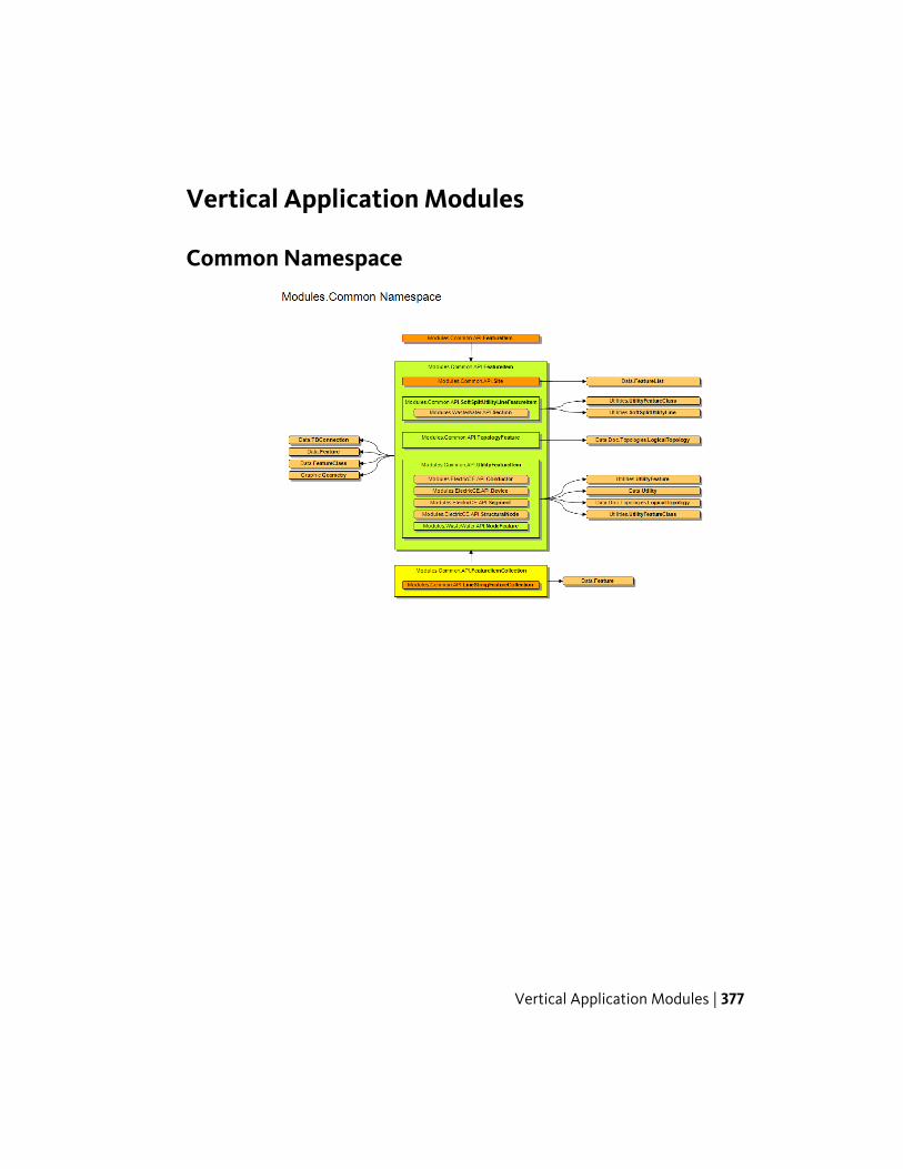
Vertical Application Modules
Common Namespace
Vertical Application Modules | 377
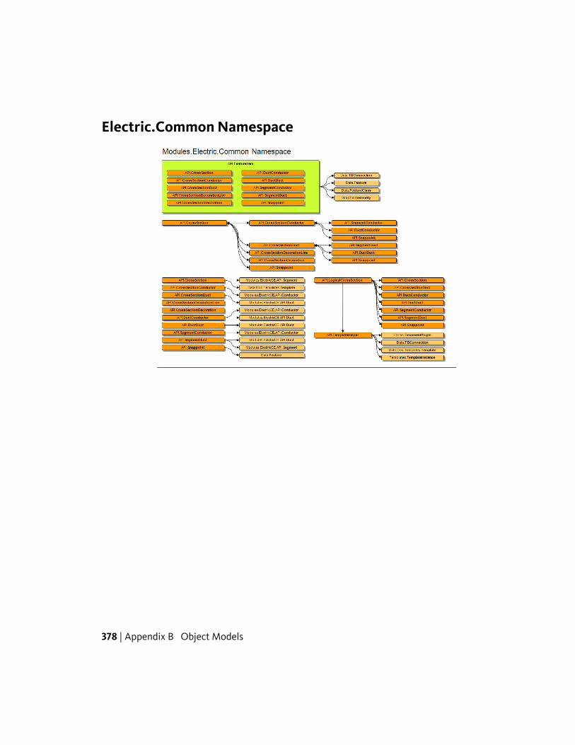
Electric.Common Namespace
378 | Appendix B Object Models
Index
A
API Reference 1application flyin sample 262application options sample 232application toolbar sample 264assembly information 81Autodesk Topobase Administrator
Guide 1
B
batch files 291
C
canvas control sample 270checked list box sample 263class call via batch file sample 291client side feature rules sample 298code samples
introduction 179Conditional loading of plugin 358confirm box sample 208connection tools sample 240control text sample 251controls sample 210create a drawing template 187create a workspace 185create all dialog boxes sample 224create structure sample 182create topobase user sample 293
D
date/time picker sample 235desktop sample 253dialog box control update sample 271dialog box flyin sample 257dialog box user controls sample 247dialog box validation sample 226
dialog button sample 203dialog events sample 207dialog menu sample 206dialog toolbar button sample 198directory text box sample 236dock in container sample 237DockableForm 237DockInContainer 237document context menu sample 195document flyin sample 211document options sample 246document toolbar button sample 196drawing template, create a 187drop down buttons sample 243DWT (drawing template) 187
F
feature explorer sample 296feature information sample 220features sample 285file download sample 221file text box sample 236file upload sample 221flyin container sample 259flyin sample 211, 257, 262forms sample 210
G
generic dialog box sample 247grid control sample 225
H
Hello World 3, 76highlight sample 218
Index | 379
I
information sample 220input box sample 208interaction sample 230introduction 1
J
jobs sample 280
L
list box multi selection sample 265list box sample 217, 244, 263list box with context menu sample 214
M
main menu sample 199main toolbar sample 201map button sample 216map function sample 288matrix control sample 228menu control sample 267menus sample 228Microsoft Visual Studio 2005 75–76multiple input box sample 208
O
ODP .Net sample 193options page with tree nodes sample 258options sample 246oracle data provider .Net sample 193overview 1
P
passwords 180picture combobox sample 290plugin
details 356example 354file format 353
test 85plugin definition file 83plugins 2
introduction 75, 353progress bar sample 213project
add references 80default class 81run from Visual Studio 79write to bin folder 78
project, create a 76
R
read/write features sample 191remote control sample 273reports sample 254
S
samplesbuilding 180common steps 181details 182introduction 179running 181usernames and passwords 180
samples, developer 179samples, preparing to run the 2script engine sample 292settings sample 246special menu items sample 245SQL export sample 266
T
tab control sample 269TBBatch.exe 291TBP 2, 83, 179, 353
details 356example 354file format 353
TBSAMPLE workspace 185TBSYS 180toolbar sample 264
380 | Index
toolbars sample 228Topobase
marketing description 2Topobase Database Server 180Topobase user sample 293tree nodes sample 258tree view sample 215treeview with context menu sample 234
U
unit support sample 294
update plugin sample 277usernames 180
W
web browser sample 268Windows menu items sample 222workflows sample 275workspace, create a 185workspace, demo 76
Index | 381

382